US1851112A - Hand tool - Google Patents
Hand tool Download PDFInfo
- Publication number
- US1851112A US1851112A US496070A US49607030A US1851112A US 1851112 A US1851112 A US 1851112A US 496070 A US496070 A US 496070A US 49607030 A US49607030 A US 49607030A US 1851112 A US1851112 A US 1851112A
- Authority
- US
- United States
- Prior art keywords
- sleeve
- nail
- grip
- terminal
- tapered
- Prior art date
- Legal status (The legal status is an assumption and is not a legal conclusion. Google has not performed a legal analysis and makes no representation as to the accuracy of the status listed.)
- Expired - Lifetime
Links
- 239000002023 wood Substances 0.000 description 7
- 210000000887 face Anatomy 0.000 description 2
- 210000003811 finger Anatomy 0.000 description 2
- 210000003128 head Anatomy 0.000 description 2
- 241000587161 Gomphocarpus Species 0.000 description 1
- 238000005452 bending Methods 0.000 description 1
- 210000003414 extremity Anatomy 0.000 description 1
- 210000005224 forefinger Anatomy 0.000 description 1
- 230000037431 insertion Effects 0.000 description 1
- 238000003780 insertion Methods 0.000 description 1
- 239000007787 solid Substances 0.000 description 1
- 210000003813 thumb Anatomy 0.000 description 1
Images
Classifications
-
- B—PERFORMING OPERATIONS; TRANSPORTING
- B25—HAND TOOLS; PORTABLE POWER-DRIVEN TOOLS; MANIPULATORS
- B25C—HAND-HELD NAILING OR STAPLING TOOLS; MANUALLY OPERATED PORTABLE STAPLING TOOLS
- B25C9/00—Nail punches
Definitions
- ouspurposes is'custonlarily made inasingle provide a nail set which is equipped with aA 1U piece, which consists oit'j an elongated grip replaceablework-engaging tip, this beingac- 'ad portion, usually cylindrical,-taperingat its complished without sacrificing any oit'v the ⁇ lower endto a cup-shaped lterminal of small necessary and desirablecharacteristics'of the K diamete'rsuitable orengaging'the head'ofa one-piece nail set.
- My improved nail set is nail to set' it below the surface ofthewoo'd. (if-rugged constructionand capable lof with ⁇ 15 Among'thecustornary uses to which na'ilset's ⁇ standing the hard usage to which a nailset 65;
- a substantially uniform angleof taper of LP- may Semimthe Sleeve dtachably to the grlp i y proximately 10o to 15 and without any pr''- ⁇ .member by' any Convement means Such as a 4U j ecting shoulders to catchvon the wood, so that Screw, thread"
- the large ma] (mty of arpetl' 90 the surface 0f this tapered portion hasfafsub ⁇ h ie ⁇ clisnec t9 h-Old a Ila-11i Set mthelr stantially continuous vtaper throudhout its e l-anc m OI: er O Str] e 1t W11; -alhamn1r length.
- the uniformly tapered surhand' is to presstang'entially dn the taperedv .50 face bears evenly on the' surface of the wood portion ofthe nailiset so asito tend to rotate 100 member.
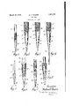
- Figure 1 is an elevation of a nail set embodying the invention, y
- Figure 2 is a fragmentary elevation of the same, drawn to a larger scale, the sleeve being shown in a section taken on the line 2 2 of Figure 1.
- Figure 3 is similar to Figure 2 but shows a prick punch terminal element in place of a nail set terminal element.
- Figure 4 is similar to Figure 2 except that a pin punch is therein illustrated.
- Figure 5 is an elevation of a nail set having a different form of grip member.
- Figure 6 is a fragment-ary elevation of the nail set shown in Figure 5, the sleeve and terminal element being shown in a section taken on the line 6-6 of Figure 5.
- Figure 7 is an elevation of another nail set embodying a slightly modified form of the invention.
- 4 Y Y Figure 8 isa fragmentary view of the nail set shown in Figure 7, the sleeve and a portion of the terminal element being shown in section on the line 8-8 of Figure 7.
- the nail set illustrated in Figure 1 comprises a grip portion 10 which is substantially cylindrical in shape and may have a knurled band 11 suitably positioned to be gripped by the thumb and fore finger.A
- the lower end of the? grip member 10 may be reduced, this lowerportion having a threaded portion 412 anda reduced cylindrical portion 13 terminating in a flat end face 14.
- a terminal element 2O abuts the face 14 in endto end engagement so that an ample'interfacial contact between thegrip member ⁇ and the terminal elementis thus provided to transmit the force of-blows on' the end of the nail set to thev work-engaging extremity.
- the terminal member 20 may be made lwith an upper tapering portion 2l and a lower portion 22 which is more steeply tapered.
- the upper portion 21 is adapted to y seat within the inside of a sleeve 23, the upper end portion of which is adapted for threaded engagement with the portion l2 of-the grip
- the wall of the sleeveJ 23 may taper downwardly in thickness, the inner surface of the lower portion of the sleeve having a taper fitted by the upper portion 2l of the'terminal element.
- the exterior surface of the sleeve 23 is preferably tapered similarly to the lower portion 22 of the terminal element so that the sleeve and the projecting portion of the terminal element present a substantially continuous and uniformly conical exposed surface which extends for a substantial fraction of the entire length of the nail set.
- the threaded portion 12 of the grip member is reduced in diameter, forming a shoulder 24 at the lower -vextremityvof the knurled portion 11 against Vlustrated in Figures 5 and 6 is substantially identical with that illustrated in Figures 1 and 2 except for the shape of the grip member.
- the grip member 30 illustrated in Figure 5 may have a square cross section, this being preferred by some carpenters; the lower portion of this grip may be tapered as at 31 and threadedto receive the sleeve 23. This structure leaves a shoulder 32 at the upper end of ⁇ the sleeve. This shoulder, however, does not interfere with the utility of the tool and is unobjectionable to those who prefer asquare grip member.
- FIGS 7 and 8 illustrate a modilied form Vof* the invention.
- a terminal element 35A is provided, this element having a tapered lower portion 36 adapted to project below the lower end of the sleeve 37.
- the portion of the terminal element within thesleeve is cylindrical as at 38, a head or button 39 being provided at its upper end to seat on an internal shoulder 40 of the ksleeve 37.
- the sleeve37 is shaped inside to receive Vthe terminal Velement 35 ⁇ and to hold this element tightly in end to end engagement with the lower end of the grip Vportion 41.
- the grip member may Lbe of any desired shape.
- a ⁇ iattened grip member is illustrated, the flattened faces being knurled, if desired.
- a nail-set or the like comprising an elongated solid grip member to be gripped ⁇ by digits of a hand, said grip member having a vcontact face at its lower end, a sleeve detachably mounted on the lower portion of said grip member and projecting therebelow, and a terminal member having a contact face at its upper end and a work-engaging portion at its lower end, theupper end portion of said terminal member being normally v engaged by said sleeve so that the two contact faces are held together in abuttingen gagement, the lateral surfaces of said sleeve and of the lower end portion of said terminal member forming a substantially continuous conical surface with a length andy degree of tion of said tool tends to oppose unscrewingv of said sleeve, and a terminal member hav-v ing an upper portion held within said sleeve in abutting end to end contact with said gripV member, and a lower work-engaging portion projecting fromsaid sle
Landscapes
- Engineering & Computer Science (AREA)
- Mechanical Engineering (AREA)
- Cosmetics (AREA)
Description
@mmm
March 29, i932.
M., F. POWERS HAND TOOL Filed Nov. 17, 1950 'do for the purpose, of releasingthe'plankfrom from thecustomaryangularity of such taper; 70?
"-'' erablefstr'e'sses,'both longitudinal andbend'-, holding `thesertwo members in endtogend 80 Patented Mar. 29, 19,32 .l Y Y Y ,Y Y,
UNITE-D- FFICEff-f i .MILmoN' PoWERs, on wmcnnsmnn; MAssAonUsE'rTs L Hmm applicatif@ 'flea VNiterate 1?,"1930; i seriino, 496,9'70,
i Ihis application is a continuationV in party andl thusavoidsz the possibility of bending* of Amy application; Serial No. 107,047 filed* the lower portion of the tapered'end. f y May 6,1926. The inventionlrelatesftohand*` One serious draw back to the `one-piece impact tools such asnail sets land the like nail set 'iszthe vliability of the tool to become VV 5 which areadaptedtobe'held in' one `hand'andl worn or injured at the work-engaging end. struck bya hammer or equivalent'tool'held It'v the workfengaging point is broken or iI'-'theother hand of the 'o'peratc` `r.` f lhefnailv otherwise injured, the .entire'tool must be re- 'set' ordinarily used byf carpenters for vari# placed.' Accordingto thepresentinvention,I
ouspurposes is'custonlarily made inasingle provide a nail set which is equipped with aA 1U piece, which consists oit'j an elongated grip replaceablework-engaging tip, this beingac- 'ad portion, usually cylindrical,-taperingat its complished without sacrificing any oit'v the` lower endto a cup-shaped lterminal of small necessary and desirablecharacteristics'of the K diamete'rsuitable orengaging'the head'ofa one-piece nail set.` My improved nail set is nail to set' it below the surface ofthewoo'd. (if-rugged constructionand capable lof with` 15 Among'thecustornary uses to which na'ilset's` standing the hard usage to which a nailset 65;
are put, are the setting of' nails withitheir ,is-'ordinarily subjected. The removable tip Y headsbelow the surface lof the w'ood',the is rigidly held'inplacewithoutsacriicing the driving of nail heads' throi'lgh,boards4 or' lcontinuousuniformi-taper ofthe lower portion planks into whichthenailshave' been driven of thetool'as a.whole,and without departing the hold of the nail', the prying'upfofldbw `A vfurther.advantage inherent in my imblefpoint'ed tacks or brads, thelniaking of' provedtoolflies inthe abilityof the-operator hOlesforthe starting of wood? screws ororA toexohange thev nail seti terminal elementffor i other purposes, insertion'thr'ongh4 screw'eyes a prick punchterminaha pin punch termi- 25y to act as 'alever in Vser'ewing'the eyesinto nal, 011 any Other Ysimilar Work-engaging 75 wood, adjusting; the tension ofd'oorsprings, member'. v Y determining Ythe bores for 'lock"spindles, and The improvedtool may consist essentially many 'other vsimilar uses. These varied u's'es ,ofi three separate pieces, a grip portion, a terofnail'sets result in rough usage'"and"consid'-` Y m'inal'j work-engaging element, and asleeve injg. In order to'sink anail'd'eeplyinto'wood,` 'abulltnglelton- `According to theinven- Y Y I it is'necessary that a considerable portionjf'ntonythe terminal'element is partlywithin 'Y the length 0f the' nai] Set be 'Capable' of' 'folfthesleevela-ndpartly projectinkg` from the lowlowing the nail into the wood.- For this rael' end hBTGOf, the @K DCSQ SUIRCGS 011th@ l 35 son, the lower portion of theV nail set?, varying" Sleeve and ,element bemg Prefefably fuormd. 85 usually between one-quartera and one-haltet' SQP-S. t0: PFQduCe 'a Substantlauy com lnuous the enuiength of the fooi, is taperedfwifh uniform @Per 0f Standard angularlty. I
a substantially uniform angleof taper of LP- may Semimthe Sleeve dtachably to the grlp i y proximately 10o to 15 and without any pr''-` .member by' any Convement means Such as a 4U j ecting shoulders to catchvon the wood, so that Screw, thread" The large ma] (mty of arpetl' 90 the surface 0f this tapered portion hasfafsub`h ie {clisnec t9 h-Old a Ila-11i Set mthelr stantially continuous vtaper throudhout its e l-anc m OI: er O Str] e 1t W11; -alhamn1r length. `This is an important eatlre of the hlchm thi? mici-ight 'ghe gr ptlltlo fooi since it facilitates the removal' of the gud fragnjr ellfdl lvgr fetheulft 95 w01 fm@ Woodmto Whmh .1t haslbeern, driven' hand restingj against the lower tapered por- I Futherrmofe, Whelftilf'nal ,S913 1S --'WEHVUD" tion of the nail set. When using a nail set, d?? fl doubllf'pmllted brgd '60 IGIDOYG the brad the tendencyof the middle inger'of the left from the wood, the uniformly tapered surhand' is to presstang'entially dn the taperedv .50 face bears evenly on the' surface of the wood portion ofthe nailiset so asito tend to rotate 100 member.
this portion with respect to the grip portion. If the sleeve of my tool were attached to the grip portion with a right hand thread, this pressure of the middle finger of the operator on the sleeve would tend to unscrew it, hence l prefer to attach the sleeve to the grip portion with a left hand thread so that the tangential pressure of the middle finger of the left hand will tend to set up the sleeve tighter on the grip portion.
Other advantageous features will be apparent to one skilled in the art from the dis-1 closure of the invention in the description which follows and the illustrations thereof on the drawings, of which,
Figure 1 is an elevation of a nail set embodying the invention, y
Figure 2 is a fragmentary elevation of the same, drawn to a larger scale, the sleeve being shown in a section taken on the line 2 2 of Figure 1.
Figure 3 is similar to Figure 2 but shows a prick punch terminal element in place of a nail set terminal element.
Figure 4 is similar to Figure 2 except that a pin punch is therein illustrated.
Figure 5 is an elevation of a nail set having a different form of grip member.
Figure 6 is a fragment-ary elevation of the nail set shown in Figure 5, the sleeve and terminal element being shown in a section taken on the line 6-6 of Figure 5.
Figure 7 is an elevation of another nail set embodying a slightly modified form of the invention. 4 Y Y Figure 8 isa fragmentary view of the nail set shown in Figure 7, the sleeve and a portion of the terminal element being shown in section on the line 8-8 of Figure 7.
The nail set illustrated inFigure 1 comprises a grip portion 10 which is substantially cylindrical in shape and may have a knurled band 11 suitably positioned to be gripped by the thumb and fore finger.A The lower end of the? grip member 10 may be reduced, this lowerportion having a threaded portion 412 anda reduced cylindrical portion 13 terminating in a flat end face 14. A terminal element 2O abuts the face 14 in endto end engagement so that an ample'interfacial contact between thegrip member `and the terminal elementis thus provided to transmit the force of-blows on' the end of the nail set to thev work-engaging extremity. rThe terminal member 20 may be made lwith an upper tapering portion 2l and a lower portion 22 which is more steeply tapered. The upper portion 21 is adapted to y seat within the inside of a sleeve 23, the upper end portion of which is adapted for threaded engagement with the portion l2 of-the grip As shown, the wall of the sleeveJ 23 may taper downwardly in thickness, the inner surface of the lower portion of the sleeve having a taper fitted by the upper portion 2l of the'terminal element. The exterior surface of the sleeve 23 is preferably tapered similarly to the lower portion 22 of the terminal element so that the sleeve and the projecting portion of the terminal element present a substantially continuous and uniformly conical exposed surface which extends for a substantial fraction of the entire length of the nail set. As shown in Figure 2, the threaded portion 12 of the grip member is reduced in diameter, forming a shoulder 24 at the lower -vextremityvof the knurled portion 11 against Vlustrated in Figures 5 and 6 is substantially identical with that illustrated in Figures 1 and 2 except for the shape of the grip member. The grip member 30 illustrated in Figure 5 may have a square cross section, this being preferred by some carpenters; the lower portion of this grip may be tapered as at 31 and threadedto receive the sleeve 23. This structure leaves a shoulder 32 at the upper end of` the sleeve. This shoulder, however, does not interfere with the utility of the tool and is unobjectionable to those who prefer asquare grip member.
Figures 7 and 8 illustrate a modilied form Vof* the invention. As therein shown, a terminal element 35A is provided, this element having a tapered lower portion 36 adapted to project below the lower end of the sleeve 37. The portion of the terminal element within thesleeve is cylindrical as at 38, a head or button 39 being provided at its upper end to seat on an internal shoulder 40 of the ksleeve 37. The sleeve37 is shaped inside to receive Vthe terminal Velement 35` and to hold this element tightly in end to end engagement with the lower end of the grip Vportion 41.
The grip member may Lbe of any desired shape. By way of variety,a {iattened grip member is illustrated, the flattened faces being knurled, if desired. l
yThese nail sets are thus capable of hard usage, thevvvork-.engaging tips, which are the portions of the nail set which are first to be broken or worn, can be easily and quickly replaced with relatively small expense, and these results are obtained without sacricing the continuous conical surface of the lower portion ofthe nail set which must extend overa very substantial fraction of the entire length of thenail setif the tool is to be capable of the uses to fwhichithe ordinary nail set is customarily put. y `1 i i f I claim: Y 1.- A nail-set orthe like having a vwork engaging terminal element with a taperedv y lower portion, an elongated grip member,` and means for removably holding said terminal element in fixed relation to said grip member, said means engaging the upper por'- tion of the terminal element and having an outer surfaceforming with the lower portion of the terminal element a substantially continuous conical surface having the lengthv and degree of taper of the tapered portion of Y an ordinary nail-set.
.2. A nail-set or the like comprising an elongated solid grip member to be gripped` by digits of a hand, said grip member having a vcontact face at its lower end, a sleeve detachably mounted on the lower portion of said grip member and projecting therebelow, and a terminal member having a contact face at its upper end and a work-engaging portion at its lower end, theupper end portion of said terminal member being normally v engaged by said sleeve so that the two contact faces are held together in abuttingen gagement, the lateral surfaces of said sleeve and of the lower end portion of said terminal member forming a substantially continuous conical surface with a length andy degree of tion of said tool tends to oppose unscrewingv of said sleeve, and a terminal member hav-v ing an upper portion held within said sleeve in abutting end to end contact with said gripV member, and a lower work-engaging portion projecting fromsaid sleeve, the exposed Y Y surfaces of said sleeve and terminal memberV forming a substantially continuous conical surface having the length and degree of taper f of the tapered portion of an ordinary nail-set. In testimony whereof Ik have aiiiXed my signature.
MILTON F. POWERS. v
like comprising an
Priority Applications (1)
| Application Number | Priority Date | Filing Date | Title |
|---|---|---|---|
| US496070A US1851112A (en) | 1930-11-17 | 1930-11-17 | Hand tool |
Applications Claiming Priority (1)
| Application Number | Priority Date | Filing Date | Title |
|---|---|---|---|
| US496070A US1851112A (en) | 1930-11-17 | 1930-11-17 | Hand tool |
Publications (1)
| Publication Number | Publication Date |
|---|---|
| US1851112A true US1851112A (en) | 1932-03-29 |
Family
ID=23971110
Family Applications (1)
| Application Number | Title | Priority Date | Filing Date |
|---|---|---|---|
| US496070A Expired - Lifetime US1851112A (en) | 1930-11-17 | 1930-11-17 | Hand tool |
Country Status (1)
| Country | Link |
|---|---|
| US (1) | US1851112A (en) |
Cited By (2)
| Publication number | Priority date | Publication date | Assignee | Title |
|---|---|---|---|---|
| WO1994012798A1 (en) * | 1992-12-03 | 1994-06-09 | Fischerwerke Artur Fischer Gmbh & Co. Kg | Securing system with a drive-in plug |
| US20110094353A1 (en) * | 2009-10-26 | 2011-04-28 | The Stanley Works | Nail set |
-
1930
- 1930-11-17 US US496070A patent/US1851112A/en not_active Expired - Lifetime
Cited By (3)
| Publication number | Priority date | Publication date | Assignee | Title |
|---|---|---|---|---|
| WO1994012798A1 (en) * | 1992-12-03 | 1994-06-09 | Fischerwerke Artur Fischer Gmbh & Co. Kg | Securing system with a drive-in plug |
| US20110094353A1 (en) * | 2009-10-26 | 2011-04-28 | The Stanley Works | Nail set |
| US8359950B2 (en) | 2009-10-26 | 2013-01-29 | Stanley Black & Decker, Inc. | Nail set |
Similar Documents
| Publication | Publication Date | Title |
|---|---|---|
| US2678853A (en) | Securing means for hammers | |
| US2847889A (en) | Gripping tool jaws | |
| US2316985A (en) | Handle | |
| US3229738A (en) | Claw hammer cap | |
| US2467284A (en) | Handle for hammers | |
| US1851112A (en) | Hand tool | |
| US2330013A (en) | Cotter pin spreader | |
| US1934706A (en) | Claw hammer | |
| US1426249A (en) | Nail-holding device | |
| US1988807A (en) | Ice pick | |
| US2825374A (en) | Screw driver | |
| US619608A (en) | Hammer | |
| US2349339A (en) | Nail holding tool | |
| US2599676A (en) | Bolt holding pliers | |
| US2408887A (en) | Screw driver | |
| GB219466A (en) | Improved claw hammer for drawing nails | |
| US851707A (en) | Handle for hammers or the like. | |
| US3261238A (en) | Facet setting tool | |
| US1490473A (en) | Nail set | |
| GB308955A (en) | Improvements in screw drivers and like hand tools | |
| US455776A (en) | Albert f | |
| US1664081A (en) | Combination tool | |
| US1771779A (en) | Tool-handle construction | |
| US1538237A (en) | Cue | |
| US754202A (en) | Nail-puller. |