US1574481A - Apparatus for and process of making pulley units - Google Patents
Apparatus for and process of making pulley units Download PDFInfo
- Publication number
- US1574481A US1574481A US665690A US66569023A US1574481A US 1574481 A US1574481 A US 1574481A US 665690 A US665690 A US 665690A US 66569023 A US66569023 A US 66569023A US 1574481 A US1574481 A US 1574481A
- Authority
- US
- United States
- Prior art keywords
- strip
- units
- blank
- unit
- shearing
- Prior art date
- Legal status (The legal status is an assumption and is not a legal conclusion. Google has not performed a legal analysis and makes no representation as to the accuracy of the status listed.)
- Expired - Lifetime
Links
Images


Classifications
-
- B—PERFORMING OPERATIONS; TRANSPORTING
- B31—MAKING ARTICLES OF PAPER, CARDBOARD OR MATERIAL WORKED IN A MANNER ANALOGOUS TO PAPER; WORKING PAPER, CARDBOARD OR MATERIAL WORKED IN A MANNER ANALOGOUS TO PAPER
- B31D—MAKING ARTICLES OF PAPER, CARDBOARD OR MATERIAL WORKED IN A MANNER ANALOGOUS TO PAPER, NOT PROVIDED FOR IN SUBCLASSES B31B OR B31C
- B31D5/00—Multiple-step processes for making three-dimensional articles ; Making three-dimensional articles
-
- Y—GENERAL TAGGING OF NEW TECHNOLOGICAL DEVELOPMENTS; GENERAL TAGGING OF CROSS-SECTIONAL TECHNOLOGIES SPANNING OVER SEVERAL SECTIONS OF THE IPC; TECHNICAL SUBJECTS COVERED BY FORMER USPC CROSS-REFERENCE ART COLLECTIONS [XRACs] AND DIGESTS
- Y10—TECHNICAL SUBJECTS COVERED BY FORMER USPC
- Y10T—TECHNICAL SUBJECTS COVERED BY FORMER US CLASSIFICATION
- Y10T156/00—Adhesive bonding and miscellaneous chemical manufacture
- Y10T156/10—Methods of surface bonding and/or assembly therefor
- Y10T156/1052—Methods of surface bonding and/or assembly therefor with cutting, punching, tearing or severing
- Y10T156/1062—Prior to assembly
- Y10T156/1074—Separate cutting of separate sheets or webs
-
- Y—GENERAL TAGGING OF NEW TECHNOLOGICAL DEVELOPMENTS; GENERAL TAGGING OF CROSS-SECTIONAL TECHNOLOGIES SPANNING OVER SEVERAL SECTIONS OF THE IPC; TECHNICAL SUBJECTS COVERED BY FORMER USPC CROSS-REFERENCE ART COLLECTIONS [XRACs] AND DIGESTS
- Y10—TECHNICAL SUBJECTS COVERED BY FORMER USPC
- Y10T—TECHNICAL SUBJECTS COVERED BY FORMER US CLASSIFICATION
- Y10T156/00—Adhesive bonding and miscellaneous chemical manufacture
- Y10T156/10—Methods of surface bonding and/or assembly therefor
- Y10T156/1052—Methods of surface bonding and/or assembly therefor with cutting, punching, tearing or severing
- Y10T156/1062—Prior to assembly
- Y10T156/1075—Prior to assembly of plural laminae from single stock and assembling to each other or to additional lamina
- Y10T156/1077—Applying plural cut laminae to single face of additional lamina
-
- Y—GENERAL TAGGING OF NEW TECHNOLOGICAL DEVELOPMENTS; GENERAL TAGGING OF CROSS-SECTIONAL TECHNOLOGIES SPANNING OVER SEVERAL SECTIONS OF THE IPC; TECHNICAL SUBJECTS COVERED BY FORMER USPC CROSS-REFERENCE ART COLLECTIONS [XRACs] AND DIGESTS
- Y10—TECHNICAL SUBJECTS COVERED BY FORMER USPC
- Y10T—TECHNICAL SUBJECTS COVERED BY FORMER US CLASSIFICATION
- Y10T156/00—Adhesive bonding and miscellaneous chemical manufacture
- Y10T156/12—Surface bonding means and/or assembly means with cutting, punching, piercing, severing or tearing
- Y10T156/125—Plural severing means each acting on a different work piece
-
- Y—GENERAL TAGGING OF NEW TECHNOLOGICAL DEVELOPMENTS; GENERAL TAGGING OF CROSS-SECTIONAL TECHNOLOGIES SPANNING OVER SEVERAL SECTIONS OF THE IPC; TECHNICAL SUBJECTS COVERED BY FORMER USPC CROSS-REFERENCE ART COLLECTIONS [XRACs] AND DIGESTS
- Y10—TECHNICAL SUBJECTS COVERED BY FORMER USPC
- Y10T—TECHNICAL SUBJECTS COVERED BY FORMER US CLASSIFICATION
- Y10T156/00—Adhesive bonding and miscellaneous chemical manufacture
- Y10T156/12—Surface bonding means and/or assembly means with cutting, punching, piercing, severing or tearing
- Y10T156/1313—Cutting element simultaneously bonds [e.g., cut seaming]
-
- Y—GENERAL TAGGING OF NEW TECHNOLOGICAL DEVELOPMENTS; GENERAL TAGGING OF CROSS-SECTIONAL TECHNOLOGIES SPANNING OVER SEVERAL SECTIONS OF THE IPC; TECHNICAL SUBJECTS COVERED BY FORMER USPC CROSS-REFERENCE ART COLLECTIONS [XRACs] AND DIGESTS
- Y10—TECHNICAL SUBJECTS COVERED BY FORMER USPC
- Y10T—TECHNICAL SUBJECTS COVERED BY FORMER US CLASSIFICATION
- Y10T29/00—Metal working
- Y10T29/34—Means for forming clench-tongue [eg, for tieband]
-
- Y—GENERAL TAGGING OF NEW TECHNOLOGICAL DEVELOPMENTS; GENERAL TAGGING OF CROSS-SECTIONAL TECHNOLOGIES SPANNING OVER SEVERAL SECTIONS OF THE IPC; TECHNICAL SUBJECTS COVERED BY FORMER USPC CROSS-REFERENCE ART COLLECTIONS [XRACs] AND DIGESTS
- Y10—TECHNICAL SUBJECTS COVERED BY FORMER USPC
- Y10T—TECHNICAL SUBJECTS COVERED BY FORMER US CLASSIFICATION
- Y10T29/00—Metal working
- Y10T29/49—Method of mechanical manufacture
- Y10T29/49002—Electrical device making
- Y10T29/4902—Electromagnet, transformer or inductor
- Y10T29/49075—Electromagnet, transformer or inductor including permanent magnet or core
- Y10T29/49078—Laminated
-
- Y—GENERAL TAGGING OF NEW TECHNOLOGICAL DEVELOPMENTS; GENERAL TAGGING OF CROSS-SECTIONAL TECHNOLOGIES SPANNING OVER SEVERAL SECTIONS OF THE IPC; TECHNICAL SUBJECTS COVERED BY FORMER USPC CROSS-REFERENCE ART COLLECTIONS [XRACs] AND DIGESTS
- Y10—TECHNICAL SUBJECTS COVERED BY FORMER USPC
- Y10T—TECHNICAL SUBJECTS COVERED BY FORMER US CLASSIFICATION
- Y10T29/00—Metal working
- Y10T29/49—Method of mechanical manufacture
- Y10T29/49453—Pulley making
- Y10T29/49455—Assembly
- Y10T29/49456—Assembly with shaping
-
- Y—GENERAL TAGGING OF NEW TECHNOLOGICAL DEVELOPMENTS; GENERAL TAGGING OF CROSS-SECTIONAL TECHNOLOGIES SPANNING OVER SEVERAL SECTIONS OF THE IPC; TECHNICAL SUBJECTS COVERED BY FORMER USPC CROSS-REFERENCE ART COLLECTIONS [XRACs] AND DIGESTS
- Y10—TECHNICAL SUBJECTS COVERED BY FORMER USPC
- Y10T—TECHNICAL SUBJECTS COVERED BY FORMER US CLASSIFICATION
- Y10T29/00—Metal working
- Y10T29/51—Plural diverse manufacturing apparatus including means for metal shaping or assembling
- Y10T29/5136—Separate tool stations for selective or successive operation on work
- Y10T29/5137—Separate tool stations for selective or successive operation on work including assembling or disassembling station
- Y10T29/5143—Separate tool stations for selective or successive operation on work including assembling or disassembling station and means to machine product
- Y10T29/5145—Separate tool stations for selective or successive operation on work including assembling or disassembling station and means to machine product to sever product to length
-
- Y—GENERAL TAGGING OF NEW TECHNOLOGICAL DEVELOPMENTS; GENERAL TAGGING OF CROSS-SECTIONAL TECHNOLOGIES SPANNING OVER SEVERAL SECTIONS OF THE IPC; TECHNICAL SUBJECTS COVERED BY FORMER USPC CROSS-REFERENCE ART COLLECTIONS [XRACs] AND DIGESTS
- Y10—TECHNICAL SUBJECTS COVERED BY FORMER USPC
- Y10T—TECHNICAL SUBJECTS COVERED BY FORMER US CLASSIFICATION
- Y10T29/00—Metal working
- Y10T29/51—Plural diverse manufacturing apparatus including means for metal shaping or assembling
- Y10T29/5191—Assembly
Definitions
- This invention relates to an apparatus and method for fabricating paper and metal to form units which may be used for the manufacture of pulleys or other articles.
- An object of this invention is to provide a method for fabricating units from stock material, which units may be assembled and finished to form a complete pulley of the general type disclosed in my application Serial No. 610,175, filed Jan. 2., 1923, or to form any other article for which such units.
- Another object of this invention is to embody suitable mechanism in a machine to automatically carry out my method and fabricate such units-and to automatically assemble them, if desired, so that they may be 7 subsequently utilized for the manufacture of pulleys, or other articles.
- Another object of this invention is to provide an automatic machine which is simple in itsconstruction and which will'quickly, efliciently and cheaply fabricate the desired units. and assemble them for the manufacture of pulleys or other articles.
- my invention comprises a method and a mechanism for feeding strips therethrough and advancing the strips simultaneously one above the other through a machine for the various operations to be performed to fabricate them into units by securing blanks from one strip concentrically to the other and perforating them and assembling them upon a receiving means.
- the mechanism also comprises means for notching one strip and striking tongues therefrom so that a blank cut therefrom may be readily secured to another strip; means for pressing a blank from one strip'into the other strip and simultaneously perforating both the blank and the second strip; and means for depositing a liquid binder u on the units simultaneously with the shearing of the units from one strip and stacking them upon a suitable recelvmg means, such as an arbor.
- I provide a mechanism which is particularly adapted for fabricating a met-a1 strip and a paper strip for the formation of units such as disclosed in my application above referred to.
- the strip frequently termed herein the paper strip may consist of any fibrous material for forming the laminae of a pulley or the like and may comprise one or a plurality of layers.
- One good material for this purpose is what is commonly known as strawboard, but there are other fibrous materials which can be utilized.
- Such paper strip may comprise one or a plurality of layers of fibrous material securedtogether in any suitable manner, as by means of an adhesive binder. If more than one layer is used, it is often desirable to crossthe grain in the various layers to ensure greater strength in the body of the fibrous material and to increase resistance against wear on the frictional engaging surface of the finished pulley.
- the fibrous material comprises a plurality of layers, either two or more layers in one strip or a plurality of strips, it is desirable to apply adhesive to one surface of each layer or strip so that the members sheared from the strips will adhere to each other.
- the strip from which the relatively hard centers for the units are fabricated is termed the metal strip, though it is obvious that it may be a. relatively hard fibrous strip or any other relatively dense material to increase the density ofthe center of the finished pulley and to form a relatively hard core, as fully set forth in my prior application.
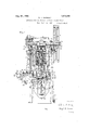
- FIG. 1 is a front elevation of a press equipped with the means for fabricating and assembling pulley units, some of the parts being in section to show their operation more clearly. 7
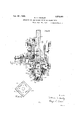
- Fig. 2 is a side elevation of the press.
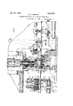
- Fig. 3 is a section of the press taken on line 3-3, Fig. 2, showing the lower half of the press in plan.
- Fig. 4 is an enlar ed view of that portion of Fig. 3 showing t e strip feeding mechanism and the dies for fabricating the strips, the portions of the outer die being shown in section.
- Fig. 5 is a vertical section through the dies for fabricating the strips taken on line 5-5, Fig. 4, and looking in the direction of the arrow.
- Fig. 6 is a vertical section taken on line 6-6, Fig. 5 and looking in the direction of the arrow.
- Fig. 7 is a plan view of one of the units formed by the press.
- Fig. 8 is an enlarged fragmentary sectional view of the unit taken on line 8-8, Fig. 7.
- Fig. 9 is a view of a plurality of units stacked on the arbor, ready to be removed from the press.
- F i 10 is an enlarged elevation of the punch.
- Fig. 11 is a section on line 11-11, F1g. 10 through the connecting portions of the punch looking upward into the punch.
- Fig. 12 is an elevation showing the means for automaticall stopping the press.
- Fig. 13 is an e evation of the opposite side of the press from that shown in Fig. 2.
- Fig. 14 is a plan view of the die.
- 1 designates the base of the machine which carries the frame 2-comprising the side uprights 3 and 4 and the top cross piece 5.
- the crank shaft 6 is journaled in the side uprights 3 and 4.
- the fly wheel 7 is carried and it may be drivenfrom any suitable source of power, such as an electric motor not shown).
- the fiy wheel 7 is mounte to rot-ate freely on the crank shaft and to drive the crank shaft when the clutch 8 is thrown into engagement.
- the crank shaft is provided with cams 9 which engage rollers 10 of reciprocating members 11, to which the ram 12 is adjustably connected by bolts 13.
- the cams 9 cause movement of the ram downward by engagement with the rollers 10.
- a counterbalance weight 14 is carried by the arm 15 which is clamped at its intermediate portion to the shaft 16, the latter being journaled in the side uprights of the frame.
- a link 17 is connected to the arm 15 and ram 12 to move the same upward as the counterbalance descends, thus causing the rollers to engage the cams 9.
- cam 18 In order to positively move the counterbalance weight substantially in synchronism with the movement of the ram, cam 18 is provided which engages the roller on the arm 19, the latter being secured to shaft 16 to turn therewith, thus ensuring the rollers 10 approximately following the cams 9 upon the upward stroke of the ram, the
- crank shaft 6 operates the connecting rod 20 which is adjustably connected to the punch 21 and causes the latter to reciprocate within the ram 12, as is customary in double acting presses of this type, there being suitable guides provided for the movement of both the ram and punch.
- this strip is the metalstrip B and its fabrication will be de scribed hereinafter.
- the die 34 Carried on the knee 30 of the machine is a bolster 31 on which is mounted subplate 32 and the die block 33 in which the die holder 34 is'mounted to carry the die 34.
- the die 34 comprises central member 37 having a central perforation to receive the perforating member 90 and it also has recesses around its periphery which, when closed by the (lie surrounding members 38, form apertures for the reception of perforating members 91 of the punch 21.
- a bridge member 35 which is cut away at 36 intermediate its ends so that it is spaced from the die 34 to provide a passage to permit the paper strip A to be fed between the bridge 35 and the die 34*.
- the metal strip B passes over the upper face of the bridge 35 where it is acted upon by the tools carried by the punch holder 25 of the ram 12, as will be more fully described hereinafter.
- Both the metal strip B and the paper strip A are advanced by the feeding means inwardly upon each'successive stroke of the press, the various positions or stations for, the paper strip A being designated d, e and f, while the metalstrip passes through stations 9, h, i, and is joined to the paper at station d to form a unit C which is not sheared from the paper strip until the latter reaches station f.
- the paper and metal strips are fed through the machine by any suitable form of feeding means, atype of finger feed being shown in the drawing.
- Each strip is simultaneously fed forward a certain definite predetermined amount with each revolution of the crank shaft and upon the upward stroke of the ram 12and the punch 21, so that the material from each strip necessary to form a single unit C is advanced one position or station at a time.
- the feeding mechanism comprises generany a means for holding the strips in position while they are being operated upon by the destending ram and punch and for releasing the strips to permit them to be advanced into the next station by other means.
- the feeding mechanism for the paper strip A comprlses pivoted fingers 40, 41, the rear ends of which are actuated by the cams 42, 43, so that the end of the finger is pressed down to clamp the strip against the stationary base member 40" or is elevatedto permit the finger 41 to clamp the strip against the movable base 41 and move inwardly to advance the strip the correct amount for the next operation.
- the cams 42, 43 are carried by the shaft 44, which is carried by brackets 45, 46 and is driven through bevel gears 47 by the similar shaft 48 for the feeding means for the metal strip, which latter shaft is carried by the brackets and 49.
- the shaft 48 is actuated through lever 50 and link 51, which in turn is operated by the cam 57 carried by the crank shaft to cause sufiicient rotation of the shafts in one direction to move the fingers into clamping position and to cause rotation in the other direction to free them from clamping position.
- the shaft 48 in a similar manner carries cams to actuate the clamping tongues 40 and 41 which clamp the metal strip against the bases 40 and 41, respectively.
- the finger 41 and base 41 are carried by the reciprocable rack 52.
- the rack 52 is actuated by the segmental gear 53 pivoted at 54 to the bolster, the gear being operated by the lever 55 which is actuated by the link 56.
- the cams 42, 43 are properly timed so that the finger 40 clamps the strip while finger 41 is in elevated position and moved outwardly.
- finger 41 descends to clamping position and. the finger 40 is caused toelevate to permit the rack and finger 41, which clamps the paper strip, to move forwardly to advance the paper strip the proper amount.
- This operation takes place while the punch and ram are ascending preparatory to the next stroke.
- the link 56 is adjustably connected to the lever 55 for actuating the segmental ear, so that the length of reciprocation for eeding the strip can be varied, so that it will be advanced the proper distance at each reciprocation of the press.
- the rack 58 with the clamping finger 41' is reciprocated by segmental gear 59. pivoted at 60, and actuated by the lever 61, to which is adjustably connected, as indicated at 62, the link 63.
- the links 56, 63 are both actuated by the cam 64 carried by the crank shaft.
- the cam 64 has an internal cam groove 65 in which one arm of the pivoted lever 66 moves, the other end of the lever directly actuating the link 56 which is' pivoted at 67 thereto.
- both feed racks are caused to simultaneously reciprocate toward the center of the machine a predetermined distance simultaneously with the upward movement of the ram after the ram has risen sufliciently to allow the strips to move.
- the metal strip passes along the top of the bridge member 35 and is first notched at station 9 by the notch punches 75 carried by the ram punch holder 25 upon downward movement of the ram 12.
- the slugs fall through the passage 76 and out of the machine.
- the notches 82 formed in the strip at this station are V-shaped notches adjacent the edges of the metal strip. with their apices disposed inwardly, so that when a single metal blank is later sheared from the strip at station 05 it is of octagonal shape and is sheared across the line joining the apices, thus making the metal center blank conform more closely to the cross sectional shape of the finished cylindrical pulley.
- the metal strip upon the next reciprocation of the press is advanced to station 71, where tongues 77 are struck down from the strip by the members 78 carried by the punch holder 25. These tongues are formed adjacent the edges of the metal strip and are for the purpose of later securing the paper and blank to ether, as will be more fully de-v scribed, to orm a complete unit such as shown in Fig 8.
- Beneath the metal strip at this position 71. is disposed in a socket 9 in the bridge 35 a spring-pressed headed pm 80 to elevate the strip B after the tongues 77 are formed therein, so that the tongues will ride above the bridge when advancing to the next station and will not become bent, but will be straight upon reaching station 03, so that they may be driven through the paper strip.
- an arch-shaped member 81 Secured to the die block 33 is an arch-shaped member 81 through which the notch punches 75 and punch member 78 pass.
- This member 81 serves actually as a stripper to prevent the metal strip B from followin the notch punches ,"7 5 and the member 78.
- the metal plate in which the tongues have just been struck advances to station 2', which is an idle station, for'the tools for performing the operations on the strip just de scribed must be wholly to one side of the paper strip in order that the slugs from the notches may pass downwardlywithout coming in contact with the paper strip and the metal blank must be concentric with but above that portion of the paper strip which is to form with it a unit 0.
- the metal blank is sheared from the metal strip and immedi ately thereafter pressed down into the surface of the paper strip, driving the tongues 77 through the paper and turning them backand clenching them, so that the paper and metal blank are secured together to form a unit.
- the box shear 85 carried by the ram 12 is provided.
- Countersunk intothebridge member 35 is a shear blade 86 over which the metal strip is fed and which cooperates with the shear blade 87 of the box'shear 85 to shear off the forward overhanging end of the metal strip 'on the line joining the apices of the notches 82 in the metal strip, and press the metal blank into the paper strip A.
- the shear After the box shear has pressed the metal blank into the paper the shear remains in this position for a definite period of the stroke, called the dwell, and which is regulated by the cams. 9.
- the box shear 85 which is detachably securedto the ram punch holder 25 of the ram 12 by any suitable means, such as screws 88, comprises a symmetrically disposed member 94 and four interchangeable shear blades 87 removably secured thereto so that they may be replaced when worn. It will be noted, however, that only one of the shear blades 87 cooperates with the shear blade 86 to shear a blank from the metal strip B.
- the box shear is a central guide 95 through which the central perforating member 90, which perforates the center hole 92 in the unit C, passes.
- Additional guides 96 are formed in the shear 85 to receive the perforating members 91 which form the required number of perforations 93 in the unit C surrounding the center hole, there being four such perforations shown in this design for later receiving the rivets.
- the guides 96 are symmetrically disposed and are formed by the conformations of the removable, interchangeable shear blades 87 It will thus be seen that the blades 87 may be interchange able or the box shear removed and secured to present any desired shear blade to the shearing position.
- the perforating members 90, 91 are removably secured to the central portion 97 of the head 98 by clamping means 99, as shown in Figs. 10 and 11, which head in turn is removably secured to the punch 21.
- the operations performed at position cl comprise perforating the center hole 92 which permits units to be passed over the arbor 100, as will be seen, and perforating the required number of rivet holes 93, there being four shown in this instance, through which rivets or dowels may be subsequently passed for securing the units together, as fully disclosed in my application above referi ed to.
- the tongues 7 7 are driven through the paper and clenched so that the metal is permanently and accurately positioned with respect to the paper for the succeeding operations.
- the paper forming the single unit, however, at station d is not severed from the paper strip at this station but the unit is carriedforward with the metal plate attached to it to station e where it is idle and thence to station f.
- the paper unit C when advanced to position f is concentric with and above the arbor 100.
- the shear 101 is adjustably mounted in the guides 102 on the forwardly extending bolster arms 103 and comprises a lower shear blade holder 104 and an upper shear blade holder 105 connected together, and the shear is carried by the overhanging portion of the bolster.
- the lower shear blade holder 104 carries guide posts 106 on which the upper shear blade holder 105 slides. Adjacent the guide posts 106 are springs 107 which keep the shear blades normally separated or in open position.
- the shear blades 108 and 109 are each set into and detachably secured to the shear blade holders.
- the upper shear blade 108 is actuated by the descent of the overhanging portion 111 of the ram 12 which comes in contact with a suitable striker member 110 on the upper portion of the upper shear blade holder and depresses it, so that the shear blades 108, 109 pass each other, thus cutting off a unit C from the paper strip.
- a stripper plate 112 Mounted upon the upper shear blade holder 105 is a stripper plate 112 having provision for Vertica motion and kept normally depressed by two springs 113, one located at each end of the stripper, so that lltl upon the downward motion of the upper 4 tion during the shearing operation, and pre-' vents the edge of the paper from being carried upwardly by the shear.
- the upper shear follows and assumes the open or normal position.
- a pot 115 contain- 'ing a suitable liquid binder to be deposited machine.
- the plunger pin 116 is pressed be used for this purpose in manufacturing" and normally holding the base of the arbor
- the upper shearl'bla de holder 105 upwardly due to its contact with, the upper end of the arbor 100, and the plate 117 carrying a plurality of valve pins 118 is lifted against the pressure of spring 119 away from the valve seats 120 to permit the liquid 25 ,binde r to run down through the apertures and upon the surface of the unit G just being pressed down on the arbor.
- the spring .119 forces the plate down and forces the valve .pins 118 against their seats 120, thus closing the openings to prevent further deposition of the binder.
- vThus at station 7 for every movement of the ram downward a unit 0 is cut off and ressed-down upon the arbor 100 and the liquid binder is deposited onits surface.
- An suitable binder such as casein glue or sodium silicate, may
- the arbor 100 together with its base 102, is yieldin ly mounted u on the inner per-- tionjof t e slide 123, t ere being sprin 124,-seated against the bottom of the sli e with its flanges 125 up against thein turned to relieve the shock of the upper sheai' holderand glue pot upon pressing the last units,"
- the handle 127 attached to the outer'portion ofthe slide 123 comprises a fixed memher 128' and a manually operated pin 129 which is yieldingly projected and manual-.
- the arborlOO is mounted for inward or outward movement with the slide in order that the assembled .units thereon may he moved outwardly to clear the overhanging portion of'the paper strip and the upper shear holder, so that the arbor with its contents can be bodily removed and replaced by anotherarbor to receive another assembly of units, after which the slide is pushed inwardly to its proper receiving location.
- the slide 123 is reciprocable in the guides 130 in" the table 131 and the table is rovided' with an additional ide 132 ilfw ich is mounted a longitudina y adjustable block 133 having a detent with which the manually operated pin engages to properly locate the slide 123 and consequently the arbor with respect to the central opening of a unit C and the pin 116 of the pot 115.
- the block 133 is internally threaded to receive the-screw 134, and the forward portion 135 of the screwis provided with a handle 136 secured thereto so that upon .turning the handle 136 the block may be adjusted to any desired position.
- a shitable clamping means 137 may be provided vto clamp the block after it has been adjusted to any desired position.
- the table 131 is carried by the base of the machine and extends into and between the forwardly projecting arms 138 of the bolster 31 and is secured to the frame of the machine by bolts 139 which are movable in the guide slots 140.
- the table is therefore vertically adjustable up and down and this -adjustment may be made by the screw 141 and hand wheel 142.
- the upper end of the screw is suitably secured in the socket 143 in theweb 144 of the table and, the lower end engages the hand wheel 142 which is mounted u on a projecting arm 145 from the base 0 the machine. It will thus be seen that upon manipulation of the hand wheel, the table maybe set to any desired position to accommodate an arbor for any predetermined number of units to be assembled thereon, as this is necessary in order to make pulleys having various widths of faces.
- adtomatic stop mechanism belng closely connected with the means for operating the Assuming the fly wheel is driven loosely ciently to engage the lug 154 of the springpressed pin 155 and cons uently movement of the member 152 pulls t e spring-pressed pin 155 out of engagement with the detent" 156 in the clutch member 157, the clutch member mounted and yieldingly urged by spring 168 toward the opposing clutch member 158 on the crank shaft when slide rod 161 and forces the same backwardly against the pressure pf the sprin 162 until the lug 160 is disposed beneat the slide rod 161, when the slide rod will be forced forwardly by the spring to engage the upper face of such lug and hold the member 152 in depressed position, so that the press operates until it is manually stopped or automatically stopped, as will be described.
- a push rod 163 is connected at one end. to the slide rod 161, the forward end being disposed so that the operator may manually push the same rearwardly.
- the slide rod is moved back against the pressure of the spring 162 which is carried in the housing 164 and this disengages the outer end 165 of the slide rod 161 from the lug 160 of the member 152, so that member 152 with its inclined surface 166 will engage the inclined surface 167 of the clutch member 157 and force the same out of'engagement with the opposing clutch member and against the pressure of the spring 168 until the detent 156 comes in ahusement with the springpressed pin 155, at which time the pin engages the 'detent and locks the clutch out of engagement.
- the shaft 16 rotates a few degrees in one direction and then in the other direction so that the arm 170 which is keyed thereto is given a reciprocating motion.
- the rack bar 171 is mounted in the guide 172 for movement vertically up and down.
- One edge of the rack bar is provided with.
- rack teeth 173 which are engaged by suitable pawls 174 and 175 to elevate the rack bar step by step.
- Secured to the side upright of the frame of the machine is a member 176 carrying guides 177 on'which is slidably mounted a similar member 178.
- These members 176 and 178 carry springpressed pawls 174 and 175, respectively, to engage the rack teeth, the rack bar being actuated vertically by these members.
- a series of holes 180 in any one of which is adapted to be placed a suitable stop member 181 to limit the downward movement of the rack bar when it is released, as will be described.
- the upper end of the rack bar the opposing clutch member thus carries an 182 to actuate the arm 183 of the bell crank lever 184, the other arm 185 of the lever being slotted to receive a pin 186 cari'ie'd by the slide rod 161.
- the rack bar 171 is caused by reciprocation of the arm 17 0 to which is connected the upper end of the rod 187. the lower end of the rod being connected to the slidable member 178.
- the rack bar may be so set that upon any predetermined number of reciprocations of the press the rack bar will be elevated sufiiciently to move the slide bar backwardly so that the member 152 can force the clutch member 157 out of engagement with the opposing clutch member and thus stop the press.
- the method comprises feeding the relatively soft fibrous strip or strips successively step by step through the machine and feeding simultaneously through, and superposed above, the relatively hard strip which is notched and tongued and, after positioning the same concentrically above the fibrous strip, a blank is then sheared off and pressed down into and secured to the fibrous strip. While so held the blank and strips are simultaneously perforated as desired, the perforating tools passing through the guides in the box shear which has pressed the blank into the fibrous strip and held it there for this operation.
- the unit is then advanced until it is above and concentric with a removable arbor when it is sheared oif and pressed down on the arbor, and at the same time receives a suitable deposit of liquid binder for binding the units together when they arepressed in another operation, as disclosed in to.
- the adjustable shear 101 must I be adjusted for wardly, that is toward the operator, so that the unit C will be sheared at the correct line to make the perforation 92 come in the center of the unit 0 when the unit is sheared from the strip. Also the block 133 must be adjusted properly so that the slide 11-3 will properly position the arbor with respect to the central perforation 92 of the unit C as it is sheared from the strip A.
- the feeding means for the strips 7 are merely indicated herein as feeding the strips substantially at right angles to each other,
- the upper strip may be of the same width or larger and blanks therefrom of the same dimension or larger than those out from the lower strip.
- my machine which will comprise blanks of. the same size and -they may be of the same or different materials.
- fibrous strips of a single rlainina'orof a plurality of la-minae can be usedfor both the strips A and B disclosed herein and when fabricated in my machine by feeding the fibrous strips atan angle to each other the grain in the units will be crossed, and this is true of course re ardless of the relative sizes or commonly furnished in rolls and thus form f units of any desired thickness and with fibrous material having the grain crossed. It is of course possible to do this in conjunction with my metal center plate herein disclosed by arranging the feeding means to feed a fibrous strip through the press at an angle to the strip A and on the side 0 posite from thaton which the strip B is fed. that is, from right to left in Fig. 3 and disposing the blanks sheared there-from so that they will be placed upon the strip A in such manner that they will be beneath and concentric with the metal plate when it is sheared and pressed down upon them.
- lamina When a plurality of relatively thin lamn a I l I. inae forming one strip is used, it is best to adjacent lamina. This can be done in any well known way as b passing the lamina; over a roll having ad esive thereon. Furthermore, when two or more fibrous strips are used, the desired surfaces of the strips may have adhesive applied thereto before reaching the shearing position, so that when a blank from an upper strip is pressed thereon it will adhere thereto.
- my machine is adapted to form and assemble fibrous units with or without a metal plate or other relatively hard member disposed thereon, which units ma be subsequently fabricated to form pul eys, gears, wheels, or any other useful articles for which they may be adapted.
- the punches to strike out tongues can be omitted and any suitable means substituted for providing securing means to hold the blank from one strip to the other strip at position (1. Or they both may approach the central position at, having been perforated previous thereto, and both be sheared ofi while at the central position, and assembled in this position upon a receiving arbor.
- the metal is not shown pressed into the surface of the fibrous material until it is entirely flush therewith. It is to be understood, however that the metal blanks can be pressed or crus ed into the body of the fibrous strip so that they are flush with the surface if desired. It is essential, however, when a relatively soft fibrous material be used beneath the metal blank that it be sufiiciently condensed to permit simultaneous perforation of the metal and fibrous material with the metal disposed on top.
- the pulley may then e finishe by boring the center hole to the correct size, forming the key seat and providing the threade apertures to receive the set screws, allas disclosed in my prior application.
- a notchmg mechanism may be rovided to notch the strip A, to remove such corners before the units are stacked on the arbor.
- the combination with means for simultaneously feeding a pair of strips, one above the other through the press in successive positionspof means for forming notches in the upper strip at one position, means for' striking, tongues in the hpper strip at an advanced position, means for shearing a blank from the upper strip and pressing it on the lower strip at an advanced position to form a unit, means for perforating the unit, and means for shearing said unit from the lower strip at an advanced position of the lower strip and depositing it upon an the forward end of said metal strip when it has advanced to a position directly above the paper strip, said shearing means being adapted to also press theblank concentri cally into the body of the paper strip to form a unit, means for perforating said unitwhile in this position, andmeans for successively shearing said units from the forward end of the paper strip with the metal member concentrically disposed there on and stacking them on a removable member.
- a machine as specified in claim 20 in which means is provided to automatically stop the machine when a predetermined number of such units has been sheared and stacked on a receiving device.
- each unit is perforated concentrically, and in which means are provided for concentrically stacking the units on a receiving member.
- means for feeding a relatively wide strip and a relatively narrow strip in different horizontal planes step by step a predetermined amount means for providing the upper strip with fastening members, means for shearing a blank .from the forward end of the upper strip and positioning it concentrically andsecuring it to the lower strip to form a unit, and means for successively shearing. theunits from the lower strip as the latter is advanced .with the feeding means.
Description
Feb. 23 1926.' 1,574,481
W. T. HENSLEY APPARATUS FOR AND PROCESS OF MAKING PULLEY UNITS Filed Sept. 29, 1923 9 Sheets-Sheet 1 auucufoz 7. Hum? Feb. 23 ,192e. 1,574,481
W. T. H ENSLEY APPARATUS FOR AND PROCESS OF MAKING PULLEY UNITS Filed Sept. 29, 1925 9 Sheets-Sheet 2 "Fig.2.
Feb. 23 1926. 1,574,481
w. T. HENSLEY APPARATUS FOR AND PROCESS OF MAKING PULLEY UNITS Filed Sept. 29, 1925 9 Sheets-Sheet 5 Feb. 23 1926.
Filed Sept. 29
, 1925 9 Sheets-Sheet 4 3141mm fun Feb. 23 ,1926. 1,574,481
' W. T. HENSLEY APPARATUS FOR AND PROCESS OF MAKING PULLEY UNITS Filed Sept. 29, 1923 9 Sheets-Sheet 5 nvcwfoz I. I' l III Feb. 23 1926.
W. T. HENSLEY APPARATUS FOR AND PROCESS OF MAKING PULLEY UNITS 1923 9 Sheets-Sheet 6 Filed Sept. 29
Feb. 23 1926. 1,574,481
w. T. HENSLEY APPARATUS FOR AND PROCESS OF MAKING PULLEY UNITS FiledSept. 29, 1923 9 Sheets-Sheet 7 i 25 ML; T
Feb. 23 ,1926., 1,574,481
W. T. HENSLEY APPARATUS FOR AND PROCESS OF MAKING PULLEY UNITS Filed Sept. 29, 1925 9 Sheets-Sheet 8 Feb. 23 1926.
W. T. HENSLEY APPARATUS FOR AND PROCESS OF MAKING PULLEY UNITS Filed Sept 29, 1925 9 Sheets-Sheet 9 Patented Feb. 23, 1926 PATENT OFFICE.
WILLIAM T. HENSLEY, F INDIANAPOLIS, INDIANA.
APPARATUS FOR AND PROCESS OF MAKING PULLEY UNITS.
Application filed September 29, 1923. Serial No. 665,690.
To all whom it may concern Be it known that I, WILLIAM T. HENSLEY,
a citizen of the United States, residing at Indianapolis, in the county of Marion and State of Indiana, have invented a certain new and useful Improvement in Apparatus for and Processes of Making Pulley Units,
of which the following is a full, clear, and
exact description, reference being had to the 1 accompanying drawings.
This invention relates to an apparatus and method for fabricating paper and metal to form units which may be used for the manufacture of pulleys or other articles.
An object of this invention is to provide a method for fabricating units from stock material, which units may be assembled and finished to form a complete pulley of the general type disclosed in my application Serial No. 610,175, filed Jan. 2., 1923, or to form any other article for which such units.
are adapted.
Another object of this invention is to embody suitable mechanism in a machine to automatically carry out my method and fabricate such units-and to automatically assemble them, if desired, so that they may be 7 subsequently utilized for the manufacture of pulleys, or other articles.
Another object of this invention is to provide an automatic machine which is simple in itsconstruction and which will'quickly, efliciently and cheaply fabricate the desired units. and assemble them for the manufacture of pulleys or other articles.
More specifically, my invention comprises a method and a mechanism for feeding strips therethrough and advancing the strips simultaneously one above the other through a machine for the various operations to be performed to fabricate them into units by securing blanks from one strip concentrically to the other and perforating them and assembling them upon a receiving means. The mechanism also comprises means for notching one strip and striking tongues therefrom so that a blank cut therefrom may be readily secured to another strip; means for pressing a blank from one strip'into the other strip and simultaneously perforating both the blank and the second strip; and means for depositing a liquid binder u on the units simultaneously with the shearing of the units from one strip and stacking them upon a suitable recelvmg means, such as an arbor.
Other objects will be apparent from the h following description and annexed drawings.
In the embodiment of my invention herein disclosed I provide a mechanism which is particularly adapted for fabricating a met-a1 strip and a paper strip for the formation of units such as disclosed in my application above referred to.
The strip frequently termed herein the paper strip may consist of any fibrous material for forming the laminae of a pulley or the like and may comprise one or a plurality of layers. One good material for this purpose is what is commonly known as strawboard, but there are other fibrous materials which can be utilized. Such paper strip may comprise one or a plurality of layers of fibrous material securedtogether in any suitable manner, as by means of an adhesive binder. If more than one layer is used, it is often desirable to crossthe grain in the various layers to ensure greater strength in the body of the fibrous material and to increase resistance against wear on the frictional engaging surface of the finished pulley. When the fibrous material comprises a plurality of layers, either two or more layers in one strip or a plurality of strips, it is desirable to apply adhesive to one surface of each layer or strip so that the members sheared from the strips will adhere to each other.
Similarly, in the embodiment herein shown the strip from which the relatively hard centers for the units are fabricated is termed the metal strip, though it is obvious that it may be a. relatively hard fibrous strip or any other relatively dense material to increase the density ofthe center of the finished pulley and to form a relatively hard core, as fully set forth in my prior application.
In the drawings, 1 Figure 1 is a front elevation of a press equipped with the means for fabricating and assembling pulley units, some of the parts being in section to show their operation more clearly. 7
Fig. 2 is a side elevation of the press.
Fig. 3 is a section of the press taken on line 3-3, Fig. 2, showing the lower half of the press in plan.
Fig. 4 is an enlar ed view of that portion of Fig. 3 showing t e strip feeding mechanism and the dies for fabricating the strips, the portions of the outer die being shown in section.
Fig. 5 is a vertical section through the dies for fabricating the strips taken on line 5-5, Fig. 4, and looking in the direction of the arrow.
Fig. 6 is a vertical section taken on line 6-6, Fig. 5 and looking in the direction of the arrow.
Fig. 7 is a plan view of one of the units formed by the press.
Fig. 8 is an enlarged fragmentary sectional view of the unit taken on line 8-8, Fig. 7.
Fig. 9 is a view of a plurality of units stacked on the arbor, ready to be removed from the press.
F i 10 is an enlarged elevation of the punch.
Fig. 11 is a section on line 11-11, F1g. 10 through the connecting portions of the punch looking upward into the punch.
Fig. 12 is an elevation showing the means for automaticall stopping the press.
Fig. 13 is an e evation of the opposite side of the press from that shown in Fig. 2.
Fig. 14 is a plan view of the die.
Referring to the drawings, 1 designates the base of the machine which carries the frame 2-comprising the side uprights 3 and 4 and the top cross piece 5. The crank shaft 6 is journaled in the side uprights 3 and 4. At one end of the crank shaft-6 the fly wheel 7 is carried and it may be drivenfrom any suitable source of power, such as an electric motor not shown). The fiy wheel 7 is mounte to rot-ate freely on the crank shaft and to drive the crank shaft when the clutch 8 is thrown into engagement.
The crank shaft is provided with cams 9 which engage rollers 10 of reciprocating members 11, to which the ram 12 is adjustably connected by bolts 13. The cams 9 cause movement of the ram downward by engagement with the rollers 10. A counterbalance weight 14 is carried by the arm 15 which is clamped at its intermediate portion to the shaft 16, the latter being journaled in the side uprights of the frame. A link 17 is connected to the arm 15 and ram 12 to move the same upward as the counterbalance descends, thus causing the rollers to engage the cams 9. In order to positively move the counterbalance weight substantially in synchronism with the movement of the ram, cam 18 is provided which engages the roller on the arm 19, the latter being secured to shaft 16 to turn therewith, thus ensuring the rollers 10 approximately following the cams 9 upon the upward stroke of the ram, the
counterbalance weight ensuring that a close contact is kept between the rollers 10 and the cams 9 in all movements of the ram.
Similarly, the crank shaft 6 operates the connecting rod 20 which is adjustably connected to the punch 21 and causes the latter to reciprocate within the ram 12, as is customary in double acting presses of this type, there being suitable guides provided for the movement of both the ram and punch.
Secured to the ram 12 is a punch holder 25 to carry the tools for working on one of the strips entering into the production of the pulley units. In the design of machine shown in the drawings, this strip is the metalstrip B and its fabrication will be de scribed hereinafter.
Carried on the knee 30 of the machine is a bolster 31 on which is mounted subplate 32 and the die block 33 in which the die holder 34 is'mounted to carry the die 34. The die 34 comprises central member 37 having a central perforation to receive the perforating member 90 and it also has recesses around its periphery which, when closed by the (lie surrounding members 38, form apertures for the reception of perforating members 91 of the punch 21. Also mounted on the die block33 is a bridge member 35 which is cut away at 36 intermediate its ends so that it is spaced from the die 34 to provide a passage to permit the paper strip A to be fed between the bridge 35 and the die 34*.
The metal strip B passes over the upper face of the bridge 35 where it is acted upon by the tools carried by the punch holder 25 of the ram 12, as will be more fully described hereinafter.
Both the metal strip B and the paper strip A are advanced by the feeding means inwardly upon each'successive stroke of the press, the various positions or stations for, the paper strip A being designated d, e and f, while the metalstrip passes through stations 9, h, i, and is joined to the paper at station d to form a unit C which is not sheared from the paper strip until the latter reaches station f.
The paper and metal strips are fed through the machine by any suitable form of feeding means, atype of finger feed being shown in the drawing. Each strip is simultaneously fed forward a certain definite predetermined amount with each revolution of the crank shaft and upon the upward stroke of the ram 12and the punch 21, so that the material from each strip necessary to form a single unit C is advanced one position or station at a time.
The feeding mechanism comprises generany a means for holding the strips in position while they are being operated upon by the destending ram and punch and for releasing the strips to permit them to be advanced into the next station by other means.
As the feeding means for either strip is quite similar, only one will be described in detail.
The feeding mechanism for the paper strip A comprlses pivoted fingers 40, 41, the rear ends of which are actuated by the cams 42, 43, so that the end of the finger is pressed down to clamp the strip against the stationary base member 40" or is elevatedto permit the finger 41 to clamp the strip against the movable base 41 and move inwardly to advance the strip the correct amount for the next operation. The cams 42, 43 are carried by the shaft 44, which is carried by brackets 45, 46 and is driven through bevel gears 47 by the similar shaft 48 for the feeding means for the metal strip, which latter shaft is carried by the brackets and 49. The shaft 48 is actuated through lever 50 and link 51, which in turn is operated by the cam 57 carried by the crank shaft to cause sufiicient rotation of the shafts in one direction to move the fingers into clamping position and to cause rotation in the other direction to free them from clamping position. The shaft 48 in a similar manner carries cams to actuate the clamping tongues 40 and 41 which clamp the metal strip against the bases 40 and 41, respectively.
The finger 41 and base 41 are carried by the reciprocable rack 52. The rack 52 is actuated by the segmental gear 53 pivoted at 54 to the bolster, the gear being operated by the lever 55 which is actuated by the link 56.
The cams 42, 43 are properly timed so that the finger 40 clamps the strip while finger 41 is in elevated position and moved outwardly. When in outward position finger 41 descends to clamping position and. the finger 40 is caused toelevate to permit the rack and finger 41, which clamps the paper strip, to move forwardly to advance the paper strip the proper amount. This operation, of course, takes place while the punch and ram are ascending preparatory to the next stroke.
The link 56 is adjustably connected to the lever 55 for actuating the segmental ear, so that the length of reciprocation for eeding the strip can be varied, so that it will be advanced the proper distance at each reciprocation of the press.
Similarly, the rack 58 with the clamping finger 41' is reciprocated by segmental gear 59. pivoted at 60, and actuated by the lever 61, to which is adjustably connected, as indicated at 62, the link 63. The links 56, 63 are both actuated by the cam 64 carried by the crank shaft. The cam 64 has an internal cam groove 65 in which one arm of the pivoted lever 66 moves, the other end of the lever directly actuating the link 56 which is' pivoted at 67 thereto. Connected to the lever 66 is a pivot link 68 which actuates the lever 69 pivoted at 70, which in turn actuates the short lever 71 connected to the upper end of the link 63, and'i-n this manner both feed racks are caused to simultaneously reciprocate toward the center of the machine a predetermined distance simultaneously with the upward movement of the ram after the ram has risen sufliciently to allow the strips to move.
The operations performed on the paper and metal strips at the various stations will now be described. The metal strip passes along the top of the bridge member 35 and is first notched at station 9 by the notch punches 75 carried by the ram punch holder 25 upon downward movement of the ram 12. The slugs fall through the passage 76 and out of the machine. The notches 82 formed in the strip at this station are V-shaped notches adjacent the edges of the metal strip. with their apices disposed inwardly, so that when a single metal blank is later sheared from the strip at station 05 it is of octagonal shape and is sheared across the line joining the apices, thus making the metal center blank conform more closely to the cross sectional shape of the finished cylindrical pulley.
The metal strip upon the next reciprocation of the press is advanced to station 71, where tongues 77 are struck down from the strip by the members 78 carried by the punch holder 25. These tongues are formed adjacent the edges of the metal strip and are for the purpose of later securing the paper and blank to ether, as will be more fully de-v scribed, to orm a complete unit such as shown in Fig 8. Beneath the metal strip at this position 71. is disposed in a socket 9 in the bridge 35 a spring-pressed headed pm 80 to elevate the strip B after the tongues 77 are formed therein, so that the tongues will ride above the bridge when advancing to the next station and will not become bent, but will be straight upon reaching station 03, so that they may be driven through the paper strip. Secured to the die block 33 is an arch-shaped member 81 through which the notch punches 75 and punch member 78 pass. This member 81 serves actually as a stripper to prevent the metal strip B from followin the notch punches ,"7 5 and the member 78.
Upon the next reciprocation of the press the metal plate in which the tongues have just been struck advances to station 2', which is an idle station, for'the tools for performing the operations on the strip just de scribed must be wholly to one side of the paper strip in order that the slugs from the notches may pass downwardlywithout coming in contact with the paper strip and the metal blank must be concentric with but above that portion of the paper strip which is to form with it a unit 0. At the position or' station d the metal blank is sheared from the metal strip and immedi ately thereafter pressed down into the surface of the paper strip, driving the tongues 77 through the paper and turning them backand clenching them, so that the paper and metal blank are secured together to form a unit.
For accomplishing this the box shear 85 carried by the ram 12 is provided. Countersunk intothebridge member 35 is a shear blade 86 over which the metal strip is fed and which cooperates with the shear blade 87 of the box'shear 85 to shear off the forward overhanging end of the metal strip 'on the line joining the apices of the notches 82 in the metal strip, and press the metal blank into the paper strip A. After the box shear has pressed the metal blank into the paper the shear remains in this position for a definite period of the stroke, called the dwell, and which is regulated by the cams. 9. During this dwell the punch 21 carrying the perforating members 90, 91 descends through the box shear 85, the latter having guides 95, 96 for the various perforating members and perforates the unit as a whole, passing through both the metal blank and paper strip or strips. Immediately underneath the box shear and concentric therewith is the die 3a located in the die holder 34* with suitable perforations 92, 93 therein to and central member 94:
receive the perforating members 90, 91, the under portion of the die being cut away to permit the slugs to fall out of the machine.
The box shear 85 which is detachably securedto the ram punch holder 25 of the ram 12 by any suitable means, such as screws 88, comprises a symmetrically disposed member 94 and four interchangeable shear blades 87 removably secured thereto so that they may be replaced when worn. It will be noted, however, that only one of the shear blades 87 cooperates with the shear blade 86 to shear a blank from the metal strip B.
Extending through the central member.
94 of the box shear is a central guide 95 through which the central perforating member 90, which perforates the center hole 92 in the unit C, passes. Additional guides 96 are formed in the shear 85 to receive the perforating members 91 which form the required number of perforations 93 in the unit C surrounding the center hole, there being four such perforations shown in this design for later receiving the rivets. The guides 96 are symmetrically disposed and are formed by the conformations of the removable, interchangeable shear blades 87 It will thus be seen that the blades 87 may be interchange able or the box shear removed and secured to present any desired shear blade to the shearing position. The perforating members 90, 91 are removably secured to the central portion 97 of the head 98 by clamping means 99, as shown in Figs. 10 and 11, which head in turn is removably secured to the punch 21.
The operations performed at position cl comprise perforating the center hole 92 which permits units to be passed over the arbor 100, as will be seen, and perforating the required number of rivet holes 93, there being four shown in this instance, through which rivets or dowels may be subsequently passed for securing the units together, as fully disclosed in my application above referi ed to.
In addition to the shearing and perforating at this station, the tongues 7 7 are driven through the paper and clenched so that the metal is permanently and accurately positioned with respect to the paper for the succeeding operations. The paper forming the single unit, however, at station d is not severed from the paper strip at this station but the unit is carriedforward with the metal plate attached to it to station e where it is idle and thence to station f. The paper unit C when advanced to position f is concentric with and above the arbor 100.
The shear 101 is adjustably mounted in the guides 102 on the forwardly extending bolster arms 103 and comprises a lower shear blade holder 104 and an upper shear blade holder 105 connected together, and the shear is carried by the overhanging portion of the bolster. The lower shear blade holder 104 carries guide posts 106 on which the upper shear blade holder 105 slides. Adjacent the guide posts 106 are springs 107 which keep the shear blades normally separated or in open position. The shear blades 108 and 109 are each set into and detachably secured to the shear blade holders. The upper shear blade 108 is actuated by the descent of the overhanging portion 111 of the ram 12 which comes in contact with a suitable striker member 110 on the upper portion of the upper shear blade holder and depresses it, so that the shear blades 108, 109 pass each other, thus cutting off a unit C from the paper strip.
Mounted upon the upper shear blade holder 105 is a stripper plate 112 having provision for Vertica motion and kept normally depressed by two springs 113, one located at each end of the stripper, so that lltl upon the downward motion of the upper 4 tion during the shearing operation, and pre-' vents the edge of the paper from being carried upwardly by the shear. Upon upward movement of the ram 12, the upper shear follows and assumes the open or normal position. v I
Adjustably mounted on the upper shear blade holder is located a pot 115 contain- 'ing a suitable liquid binder to be deposited machine.
v is depressed, the plunger pin 116 is pressed be used for this purpose in manufacturing" and normally holding the base of the arbor When the upper shearl'bla de holder 105 upwardly due to its contact with, the upper end of the arbor 100, and the plate 117 carrying a plurality of valve pins 118 is lifted against the pressure of spring 119 away from the valve seats 120 to permit the liquid 25 ,binde r to run down through the apertures and upon the surface of the unit G just being pressed down on the arbor. 1 Upon movement upward of thepot, the spring .119 forces the plate down and forces the valve .pins 118 against their seats 120, thus closing the openings to prevent further deposition of the binder. vThus at station 7 for every movement of the ram downward a unit 0 is cut off and ressed-down upon the arbor 100 and the liquid binder is deposited onits surface. An suitable binder, such as casein glue or sodium silicate, may
pulleys. p
The arbor 100, together with its base 102, is yieldin ly mounted u on the inner per-- tionjof t e slide 123, t ere being sprin 124,-seated against the bottom of the sli e with its flanges 125 up against thein turned to relieve the shock of the upper sheai' holderand glue pot upon pressing the last units,"
1 machine, will be described in con unction -therewith.
C down upon the arbor.
The handle 127 attached to the outer'portion ofthe slide 123 comprises a fixed memher 128' and a manually operated pin 129 which is yieldingly projected and manual-.
ly withdrawn for a purpose about to be described.
The arborlOO is mounted for inward or outward movement with the slide in order that the assembled .units thereon may he moved outwardly to clear the overhanging portion of'the paper strip and the upper shear holder, so that the arbor with its contents can be bodily removed and replaced by anotherarbor to receive another assembly of units, after which the slide is pushed inwardly to its proper receiving location.-
The slide 123 is reciprocable in the guides 130 in" the table 131 and the table is rovided' with an additional ide 132 ilfw ich is mounted a longitudina y adjustable block 133 having a detent with which the manually operated pin engages to properly locate the slide 123 and consequently the arbor with respect to the central opening of a unit C and the pin 116 of the pot 115. The block 133 is internally threaded to receive the-screw 134, and the forward portion 135 of the screwis provided with a handle 136 secured thereto so that upon .turning the handle 136 the block may be adjusted to any desired position. In addition, a shitable clamping means 137 may be provided vto clamp the block after it has been adjusted to any desired position.
The table 131 is carried by the base of the machine and extends into and between the forwardly projecting arms 138 of the bolster 31 and is secured to the frame of the machine by bolts 139 which are movable in the guide slots 140. The table is therefore vertically adjustable up and down and this -adjustment may be made by the screw 141 and hand wheel 142. The upper end of the screw is suitably secured in the socket 143 in theweb 144 of the table and, the lower end engages the hand wheel 142 which is mounted u on a projecting arm 145 from the base 0 the machine. It will thus be seen that upon manipulation of the hand wheel, the table maybe set to any desired position to accommodate an arbor for any predetermined number of units to be assembled thereon, as this is necessary in order to make pulleys having various widths of faces. v
" In order to provide an automatic mech- Ianismfor stoppinglhe machine when any predetermined num r of units necessary to make apulley of any given width of face "has been assembled upon the arbor 100, I have designed an automatic stop mechanism, flanges 126 of the slide. This order,
adtomatic stop mechanism, belng closely connected with the means for operating the Assuming the fly wheel is driven loosely ciently to engage the lug 154 of the springpressed pin 155 and cons uently movement of the member 152 pulls t e spring-pressed pin 155 out of engagement with the detent" 156 in the clutch member 157, the clutch member mounted and yieldingly urged by spring 168 toward the opposing clutch member 158 on the crank shaft when slide rod 161 and forces the same backwardly against the pressure pf the sprin 162 until the lug 160 is disposed beneat the slide rod 161, when the slide rod will be forced forwardly by the spring to engage the upper face of such lug and hold the member 152 in depressed position, so that the press operates until it is manually stopped or automatically stopped, as will be described.
A push rod 163 is connected at one end. to the slide rod 161, the forward end being disposed so that the operator may manually push the same rearwardly. When the rod 163 is pushed rearwardly the slide rod is moved back against the pressure of the spring 162 which is carried in the housing 164 and this disengages the outer end 165 of the slide rod 161 from the lug 160 of the member 152, so that member 152 with its inclined surface 166 will engage the inclined surface 167 of the clutch member 157 and force the same out of'engagement with the opposing clutch member and against the pressure of the spring 168 until the detent 156 comes in ahnement with the springpressed pin 155, at which time the pin engages the 'detent and locks the clutch out of engagement.
Means for automatically throwing out the clutch and stopping the press when a predetermined number of units has been assembled on the arbor will now be described. As previously described, the shaft 16 rotates a few degrees in one direction and then in the other direction so that the arm 170 which is keyed thereto is given a reciprocating motion. The rack bar 171 is mounted in the guide 172 for movement vertically up and down. One edge of the rack bar is provided with. rack teeth 173 which are engaged by suitable pawls 174 and 175 to elevate the rack bar step by step. Secured to the side upright of the frame of the machine is a member 176 carrying guides 177 on'which is slidably mounted a similar member 178. These members 176 and 178 carry springpressed pawls 174 and 175, respectively, to engage the rack teeth, the rack bar being actuated vertically by these members.
Located in the frame members 3 and 6 in alinement with the rack bar 171 is provided a series of holes 180 in any one of which is adapted to be placed a suitable stop member 181 to limit the downward movement of the rack bar when it is released, as will be described. The upper end of the rack bar the opposing clutch member, thus carries an 182 to actuate the arm 183 of the bell crank lever 184, the other arm 185 of the lever being slotted to receive a pin 186 cari'ie'd by the slide rod 161. Continued upward movement of the rack bar 171 is caused by reciprocation of the arm 17 0 to which is connected the upper end of the rod 187. the lower end of the rod being connected to the slidable member 178. One reciprocation of the press will cause the rod to move the rack bar up one notch and upon the downward movement of the arm 170 and rod 187 the rack bar will be held by the pivoted pawl 175 of the fixed member 176 while the upper pawl 174 will move down along the rack bar to engage the next rack tooth. It is obvious, therefore, that the rack bar may be so set that upon any predetermined number of reciprocations of the press the rack bar will be elevated sufiiciently to move the slide bar backwardly so that the member 152 can force the clutch member 157 out of engagement with the opposing clutch member and thus stop the press.
When the member 152 moves upwardly, throwing the clutch out of engagement, the foot treadle 150 is also moved upwardly and the rod 190, which has pins 191, 192 secured thereto, causes the pawls 17 4, 175 to be elevated so that the rack bar does not engage the pawls and is free to drop downwardly until its movement is limited by the adjustable stop member 181, the position of which has been previously determined. When the foot treadle is again depressed this cycle will be repeated and another assembly of units formed on the arbor 100 and the press automatically stopped.
It will thus be seen that the fabrication of units 0 and their assembly on arbors for finishing intfo completed pulleys is automatically accomplished by utilizing my machine and my method ofmanufacture. Briefly, the method comprises feeding the relatively soft fibrous strip or strips successively step by step through the machine and feeding simultaneously through, and superposed above, the relatively hard strip which is notched and tongued and, after positioning the same concentrically above the fibrous strip, a blank is then sheared off and pressed down into and secured to the fibrous strip. While so held the blank and strips are simultaneously perforated as desired, the perforating tools passing through the guides in the box shear which has pressed the blank into the fibrous strip and held it there for this operation. The unit is then advanced until it is above and concentric with a removable arbor when it is sheared oif and pressed down on the arbor, and at the same time receives a suitable deposit of liquid binder for binding the units together when they arepressed in another operation, as disclosed in to.
It will also be seen that with my machine provisioniis made for fabricating strips of varying widths and shearing them to various lengths to form rectangular units of different sizes, so that an assembly of units, of different dimensions can be made on this machine. Furthermore, the various elements of the machine are adjustable, so that desired numbers of units of desired dimensions may be assembled upon the arbors to later form finished pulleys having different diameters or widths of faces. It is of course obvious also that by changing the tools the center hole and rivet holes may be made of various sizes and any desired number of rivet holes can be made instead of the four holes herein shown, and they can be dis-' posed. as desired.
For example, if it be desired to make units C larger than those indicated in the set up of the machine shown in the drawings, it is necessary to provide anew ram punch holder ,with the notching punches and tongue members properly disposed to cor respondingly notch and tongue a wider strip B. It is also necessary to provide a die of the proper size to receive the corresponding perforating members. The adjustable connections between the link 56 and lever 55 and between the link 63 and lever 61 must be adjusted so that the strips A and B will be fed forward at each reciprocation of the press larger amount corresponding to the increase in the width of the strips. The adjustable shear 101 must I be adjusted for wardly, that is toward the operator, so that the unit C will be sheared at the correct line to make the perforation 92 come in the center of the unit 0 when the unit is sheared from the strip. Also the block 133 must be adjusted properly so that the slide 11-3 will properly position the arbor with respect to the central perforation 92 of the unit C as it is sheared from the strip A.
While I have shown as my preferred form a base with the arbor thereon for receiving the various units after they have been sheared, it is obvious that the units may be stacked on a base with suitable side guides or other means, it being essential only that they be substantially concentrically assembled in piles of a. predetermined number, ready to have the rivets passed through them and to be pressed, as previously referred to. In this connection it will also be seen that it is of considerable value to provide assemblies of units of a predeter mined number, so that they may. be quickly my prior application referred.
removed by the operator. without counting them and finished to form a pulley of a pre- .ing tools must be supplied to obtain. any
predetermined size of unit.
The feeding means for the strips 7 are merely indicated herein as feeding the strips substantially at right angles to each other,
but this is a matter of convenience, asiit is readily conceivable that the strips may be T fed parallel to one another or'at other angles,
and the other fabricating means can be arranged to produce the same results.
It will also be noted that while I have shown the upper strip as being narrow to form blanks o'f less dimension than those from the lower strip,,the upper strip may be of the same width or larger and blanks therefrom of the same dimension or larger than those out from the lower strip. Thus units can be made with my machine which will comprise blanks of. the same size and -they may be of the same or different materials.
In case it is not desired to fabricate units with relatively small dense centers, fibrous strips of a single rlainina'orof a plurality of la-minae can be usedfor both the strips A and B disclosed herein and when fabricated in my machine by feeding the fibrous strips atan angle to each other the grain in the units will be crossed, and this is true of course re ardless of the relative sizes or commonly furnished in rolls and thus form f units of any desired thickness and with fibrous material having the grain crossed. It is of course possible to do this in conjunction with my metal center plate herein disclosed by arranging the feeding means to feed a fibrous strip through the press at an angle to the strip A and on the side 0 posite from thaton which the strip B is fed. that is, from right to left in Fig. 3 and disposing the blanks sheared there-from so that they will be placed upon the strip A in such manner that they will be beneath and concentric with the metal plate when it is sheared and pressed down upon them.
When a plurality of relatively thin lamn a I l I. inae forming one strip is used, it is best to adjacent lamina. This can be done in any well known way as b passing the lamina; over a roll having ad esive thereon. Furthermore, when two or more fibrous strips are used, the desired surfaces of the strips may have adhesive applied thereto before reaching the shearing position, so that when a blank from an upper strip is pressed thereon it will adhere thereto.
It will thus be seen that my machine is adapted to form and assemble fibrous units with or without a metal plate or other relatively hard member disposed thereon, which units ma be subsequently fabricated to form pul eys, gears, wheels, or any other useful articles for which they may be adapted.
It will be seen that when it is desired to use only paper or fibre strips the punches to strike out tongues can be omitted and any suitable means substituted for providing securing means to hold the blank from one strip to the other strip at position (1. Or they both may approach the central position at, having been perforated previous thereto, and both be sheared ofi while at the central position, and assembled in this position upon a receiving arbor.
In the units shown in the drawing the metal is not shown pressed into the surface of the fibrous material until it is entirely flush therewith. It is to be understood, however that the metal blanks can be pressed or crus ed into the body of the fibrous strip so that they are flush with the surface if desired. It is essential, however, when a relatively soft fibrous material be used beneath the metal blank that it be sufiiciently condensed to permit simultaneous perforation of the metal and fibrous material with the metal disposed on top.
In the manufacture of pulley units it is preferable in most instances to ress the metal sufiiciently into the straw card or other fibrous material so that the u per surface is substantially flush. This acilitates the spreading of the drops of liquid binder that are dropped on the surface of the units when they are stacked on the arbor due to the pressing action thereon which causes them to engage throughout their entire surfaces. Also, in case it is undesirable to have the binder dry out, it is preferable to have no spaces between the various units in the pile. It is obvious, however, that this matter can be arranged at the will of the operator to secure results desired.
When it is desired to form complete ulleys such as disclosed in my prior app 1cation referred to. the assembly of units stacked on the arbor is removed and rivet bars are inserted through alined apertures in said units. End plates are then disposed thereon and the whole assembly pressed together and the ends of the rivets are split or (partiallylexpanded, to hold the end plates assemb 1n position for d The fibrous mass is then dried, during wfich (i5- eration it shrinks. After the p leys are again pressed to take up the shrinkage and to head the rivets over to hold the end plates tightl in sition against the body of the pul ey w ich is permanently shrunk by the ing process.- The assembly is then fimshed by the outer surface of the' ulley, as by turning, until it is substantia y cylindrical. It may of course be finished with a crowned surface such. as is common] used in. ulleys.
The pulley may then e finishe by boring the center hole to the correct size, forming the key seat and providing the threade apertures to receive the set screws, allas disclosed in my prior application.
In case it is desired to have the corners of the units removed or to have them more nearly circular, so that there will be less trimming or turnin required to -form the finished, substantia y cylindrical pulley, it is obvious that a notchmg mechanism may be rovided to notch the strip A, to remove such corners before the units are stacked on the arbor.
Furthermore it' is to be understood that the particular forms of a paratus shown and described, and the particular procedure set forth, are presented for purposes of explanation and illustration and that various modifications of said apparatus and rocedure can be made without de arting m my invention as defined in t e appended claims.
What I claim is:
1. In a machine of the class described, the combination with means for advancing a plurality of strips cen ter of the machine, in difierent horizontal planes, of means for shearing blanks from each of said strips, and means for stacking the blanks concentrically upon a receiving member in the same relative vertical poslt'zon.
2. In a machine of the class described, the combination with means. for advancing a plurality of strips the-rethrough toward the center of the machine, in different horizontal planes and at an angle to each other, of means for shearing blanks from each of said strips, and means for stacking the blanks concentrically upon a receiving member in the same relative vertical sition.
3. In a machine of the e s described, the combination with means for feeding a plurality of strips. of means for successively cutting oifand positioning blanks from one therethrough toward the strip substantially concentrically on successive portions of another strip to form units, means for separating successively the units from the second named strip.
4. The combination with a press, of means for feeding a plurality of strips, means for of another strip to"form units, means for separating successively the units from the second named strip and. assembling them substantially concentrically in a pile.
5. The combination specified in claim 4- in which there is meansfor depositing a liquid binder upon each unit during the separating operation. a
6. In a machine of the class described, the combination with a means for feeding a pair of strips one disposed above the other hrough the press, of means for cutting off the forward portion ofthe upper strip and positioning it concentrically on the lower strip upon each reciprocation of the press to form a unit, and means for successively shearing said units from said lower strip and simultaneously stacking them in a pile.
7. In a machine the combination with means for feeding strips therethrougl one above the other, of means for shearing a blank from the forward portion of one strip and depositing it concentrically on the other strip to form a unit, means for perforating the unit centrally, and means for shearing the unit from the sezond named strip and depositing it upon a receiving device by means of said central perforation.
8. The combination claimed in claim 7 in which the shearing means is adjustable to shear the units of such a length that units of suitable predetermined size may be sheared with the blank concentrically disposed thereon.
9. The combination claimed in claim 7 in which a means is provided for depositing a liquid binder upon the surface of each unit when it is deposited upon the receiving device.
1.0. In a machine of the class, described,
the combination with means for feeding a first strip step by step therethrough, of means for feeding a second strip simultaneously step by step therethrough above the first strip, means for shearing a blank from the forward end of the second strip 'and pressing it on said first strip, means for per forating the blank and second strip when in this position, and means for successively shearing off the forward ends of the first strip and depositing them with the blanks thereon concentrically upon a receiving device.
11. The combination with a press, of means for advancing a fibrous strip step by step therethrough, means for advancing a metal strip therethrough, means for shearing a blank from the forward end of the metal strip and placing it concentrically upon the paper strip, and means for shearing off the forward end of the paper strip with the metal plate concentrically disposed thereon.
12. The combination with a.- machine, of means for advancing a first strip and a second strip throughthe machine, means. for concentrically depositing a. blank fromthe forward portion of the first strip on thesecond strip, means for advancing the second strip and inc-ans sheafing off the forward end of the second strip with the blank concentrically disposed'thereon.
13. The combination specified in claim 12, in which a means is provided for concentrically perforating the blank and second strip.
14. The combination specified in claim 12, in which a means is provided for simultaneously stacking the units of the second strip concentrically. 1
15. The combination with a press, of means for, feeding a pair of strips, one disposed above the other through the press, means for cutting ablank from the forward portion of the upper strip, placing it and r holding it concentrically on the lower strip,
means for perforating the blank and strip while so held, and means for successively shearing units from said lower strip with the blanks thereon and simultaneously assembling them in a pile.
16. In a machine of the class described the combination with means for feeding a pair of strips one disposed above the other through this press, of .punches for notching the upper strip, punches for striking tongues therein, means for shearing the forward end of said strip and pressing said sheared portion concentrically upon the lower strip to form a unit, meansfor perforating the unit, and means for successively shearing said units from the lower strip and assembling them in a pile. I I
17. In a machine of the class described the combination with means for simultaneously feeding a pair of strips, one above the other through the press in successive positionspof means for forming notches in the upper strip at one position, means for' striking, tongues in the hpper strip at an advanced position, means for shearing a blank from the upper strip and pressing it on the lower strip at an advanced position to form a unit, means for perforating the unit, and means for shearing said unit from the lower strip at an advanced position of the lower strip and depositing it upon an the forward end of said metal strip when it has advanced to a position directly above the paper strip, said shearing means being adapted to also press theblank concentri cally into the body of the paper strip to form a unit, means for perforating said unitwhile in this position, andmeans for successively shearing said units from the forward end of the paper strip with the metal member concentrically disposed there on and stacking them on a removable member.
19. In a machine of the class described the combination with means for feeding a paper strip and a metal strip step by step through a press in different horizontal planes of means for notching the metal strip in one position, means for striking tongues therefrom in an advanced position, and means for shearing a blank from the forward end of the metal strip when it is concentrically positioned above the paper strip and pressing said tongues into the paper strip to secure the blank thereto to form a unit, means for perforating said unit, and means for shearing successively such units from said paper strip and stacking them upon a remova-blemember.
20. In a machine of the class described the combination with means for progressively advancing a. pair of strips simultaneously in different horizontal planes of means for shearing a blank from the forward end of the upper strip and pressing the blank on the lower strip to form a unit, means for successively shearing the units from the lower strip and means for successively stacking such units and applying a binding means thereto.
21. A machine as specified in claim 20 in which means is provided to automatically stop the machine when a predetermined number of such units has been sheared and stacked on a receiving device.
22. In a machine of the class described the combination with means for progressively advancing a pair of strips simultaneously in different horizontal planes of means for shearing a blank from the forward end of the upper strip and pressing the blank on the lower strip to form a unit, means for perforating the unit, means for shearing successively the units from the lower strip and means for stacking the units on a removable member.
23. In a machine .of the class described the combination with means for feeding a pair of strips disposed at an angle to each other and in different horizontal planes of means for shearing a blank from the forward end of the upper strip and positioning it concentrically upon the lower strip to form a unit, and means for successively shearing the units from the lower strip and stacking them concentrically upon a receiving member.
24. The combination with a press, of
means for feeding a pair of strips disposed at an angle to each other and in different horizontal planes step by step a predetermined amount for each reciprocation of the press, means for shearing a blank from the upper strip and positioning it upon the lower strip to form a unit, means for erfo rating the unit during the same period of rest of the lower strip, and means for suc- .cessively shearing the units from the lower strip and simultaneously stacking them concentrically.
25. The combination specified in claim 24 'in which means are provided for adjusting the shearing means to shear units from various sized strips so that the blank is concentrically disposed on the unit.
26. The combination with a press, of means for advancing a fibrous strip step by step therethrough, means for advancing a relatively narrower strip simultaneously step by step therethrough, means for shearin g a blank from the narrow strip and pressing it concentrically into the body of the fibrous strip to form a unit, means for perforating the unit, and means for shearing the unit from the fibrous strip.
27. The combination specified in claim 26 in which each unit is perforated concentrically, and in which means are provided for concentrically stacking the units on a receiving member.
28. The combination specified in claim 26 in which means for depositing a liquid binder upon each unit is provided.
29. The combination claimed in claim 26 in which means are provided for stacking the units concentrically on a receiving memler and means are provided for automatically stopping the press when a predetermined number of units has been assembled on the receiving member.
30. The combination specified in claim 26 in which means are provided on the blank for securing the blank to the lower strip when the blank is pressed thereon.
31. In a machine of the class described, the combination with a means for feeding a relatively soft strip and a relatively hard strip simultaneously therethrough in difierent horizontal planes of means for shearing a blank from the forward end of the relalively hard strip and pressing the blank down into the relatively soft strip to positlon it substantially concentrically there and secure it thereto to form a unit and means for shearing successively such units from the relatively soft strip upon successive advancement thereof.
32. The combination specified in claim 31 in which tongues'are struck from the relatively hard strip before the blank is sheared therefrom to assist in securing the blank to the relatively soft stri 33. The combination specified in claim 31 in which the unit is perforated with a center hole and rivet or dowel holes before itcis sheared ofi.
34. The combination specified in claim 31 in which the units are successively stacked concentrically on a receiving member.
35. In a machine of the class described the combination with means for feeding a relatively wide strip and a relatively narrow strip in different horizontal planes therethrough step by step a predetermined amount, of means for shearing a blank from the forward'end of the relatively narrow upper strip and. means for pressing it concentrically into the body of the lower strip to form a unit. 36. The combination specified in claim 35 in,which means are provided for perforating the units so that they may be stacked on an arbor, and means for stacking them upon the arbor.
37 The combination specified in claim 35 in which the press is provided with means for automatically stopping it when a predetermined number of units have been stacked upon the arbor.
38. Thecombination with a press, of-
means for feeding a relatively wide strip and a relatively narrow strip in different horizontal planes step by step a predetermined amount, means for providing the upper strip with fastening members, means for shearing a blank .from the forward end of the upper strip and positioning it concentrically andsecuring it to the lower strip to form a unit, and means for successively shearing. theunits from the lower strip as the latter is advanced .with the feeding means.
39. In a machine of the class described the combination with means for simultaneously feeding a paper strip and metal strip a predetermined amount step by step, means for cutting blanks from the metal strip and pressingthem .successively into successive portions of the paper strip to form units, and means for cutting the units from the paper strip.
40. The combination with a press, of
means for feeding through the press a pa er and a metal strip. at an angle to each ot er and in different horizontal planes step by step a predetermined amount, means for notching ,the metal strip in one position, means for striking tongues therefrom in an advanced position, means for shearing a blank from the end ofthe metal strip across the apices of the notches and pressing the blank onto the sur;
face of the paper strip to form a unit-fend securing 1t thereto, means for simultanenusly perforating a center hole and rivet holes in the unit, means for severingthe unit from the paper strip in. an advanced position thereof 1ne ans for the unit with its central aperture disposed upon an arbor and simultaneously coating the unit with a binder, a crank shaft provided with cams and connecting rods for actuating each of said means in proper time relation, means for driving the crank shaft, and means for automatically stopping the crank shaft when a predetermined number of units has been stacked upon the arbor.
41. In a machine of the class described, the, combination with .a means for guiding a relative narrow metalstrip and a fibrous strip therethrough, of adjustable means for advancing said strips a predetermined amount, means for shearing a blank from the metal strip and pressing it into the body of the other strip, meansfor perforating simultaneously the blank and second stripwhile the blank is held thereon, and means for shearing successively the forward portions of the second strip.
42. The combination specified in claim 41 in which the means for shearing the forward portions of the second strip 15 adjustable so that any predetermined length may be sheared from the forward portion of the' second strip.
43. The combination with a press, of
the surface of the fibrous strip, when said blank is concentrically positioned with re-. spet to the width of thefibrous strip, to for& a unit, means for perforating a central aperture and additional apertures in said unit, means for shearing successively the units from said fibrous str1p, and means for stacking said units concentrically on a receiving member. 5
44. The combination with a-double acting cam, press,'of a cam shaft with a fly wheel for driving same, a ram reciprocable by said cam shaft, a punch reciprocable by said cam shaft and. guided within said ram, means for advancing tion of the press a atively wide strip through the press from'the' rear, feeding and guiding means for advancing upon each repon each reciprocare ciprocation of the press a relatively narrow strip through the ress at substantially right angles to said wi e strip, notching punches and tongue striking punches carried by said ram and disposed to notch and strike tongues in portions of said narrow strip, a shear carrie'dby said. ram for cutting off a blank .from the forward end of said narrow strip I and pressing said blank onto said wide strip to form a unit, said cam shaft being de-
Priority Applications (1)
| Application Number | Priority Date | Filing Date | Title |
|---|---|---|---|
| US665690A US1574481A (en) | 1923-09-29 | 1923-09-29 | Apparatus for and process of making pulley units |
Applications Claiming Priority (1)
| Application Number | Priority Date | Filing Date | Title |
|---|---|---|---|
| US665690A US1574481A (en) | 1923-09-29 | 1923-09-29 | Apparatus for and process of making pulley units |
Publications (1)
| Publication Number | Publication Date |
|---|---|
| US1574481A true US1574481A (en) | 1926-02-23 |
Family
ID=24671166
Family Applications (1)
| Application Number | Title | Priority Date | Filing Date |
|---|---|---|---|
| US665690A Expired - Lifetime US1574481A (en) | 1923-09-29 | 1923-09-29 | Apparatus for and process of making pulley units |
Country Status (1)
| Country | Link |
|---|---|
| US (1) | US1574481A (en) |
Cited By (5)
| Publication number | Priority date | Publication date | Assignee | Title |
|---|---|---|---|---|
| US2753619A (en) * | 1952-10-23 | 1956-07-10 | Albert W Franklin | Method and apparatus for stamping and adhering conductive elements to nonconductive bases |
| US2957689A (en) * | 1950-10-11 | 1960-10-25 | Cons Cigar Corp | Tear tab machine |
| US2978706A (en) * | 1959-10-20 | 1961-04-11 | Brooks Co E J | Tag applying apparatus |
| US3091987A (en) * | 1955-09-07 | 1963-06-04 | Wallis Lionel Selby | Guillotines |
| US3129489A (en) * | 1959-03-16 | 1964-04-21 | Enamel Products | Splicer |
-
1923
- 1923-09-29 US US665690A patent/US1574481A/en not_active Expired - Lifetime
Cited By (5)
| Publication number | Priority date | Publication date | Assignee | Title |
|---|---|---|---|---|
| US2957689A (en) * | 1950-10-11 | 1960-10-25 | Cons Cigar Corp | Tear tab machine |
| US2753619A (en) * | 1952-10-23 | 1956-07-10 | Albert W Franklin | Method and apparatus for stamping and adhering conductive elements to nonconductive bases |
| US3091987A (en) * | 1955-09-07 | 1963-06-04 | Wallis Lionel Selby | Guillotines |
| US3129489A (en) * | 1959-03-16 | 1964-04-21 | Enamel Products | Splicer |
| US2978706A (en) * | 1959-10-20 | 1961-04-11 | Brooks Co E J | Tag applying apparatus |
Similar Documents
| Publication | Publication Date | Title |
|---|---|---|
| DE2442868C3 (en) | Machine for forming a tubular folding box | |
| CH629419A5 (en) | METHOD AND DEVICE FOR THE PRODUCTION OF OPEN-SIDED OPEN, DRUM-LIKE CONTAINERS OF ROUND OR SQUARE CROSS-SECTIONAL DESIGN FROM SOLID OR CARDBOARD. | |
| US1574481A (en) | Apparatus for and process of making pulley units | |
| US1714468A (en) | Metal-screen-making machine | |
| US2163923A (en) | Partition fabricating machine | |
| US1389197A (en) | Tray-making machine | |
| US1481332A (en) | Feeding device | |
| US2095139A (en) | Working method and machine for the manufacture of sticking paper strips provided with loop handles for carrying purposes | |
| US1847515A (en) | Machine for making blanks for cardboard boxes | |
| US1721431A (en) | Box-making machine | |
| US1614522A (en) | Box-making machine | |
| US589595A (en) | Blanking or studding machine | |
| US170039A (en) | Improvement in paper-box machines | |
| US1773511A (en) | Machine for use in making boxes | |
| US1373462A (en) | Gromet making and setting machine | |
| US2380440A (en) | Method of making fiber container parts | |
| US1854063A (en) | Ooooooooqoo | |
| US2186892A (en) | Method and means of making fasteners | |
| US2334213A (en) | Machine for making container parts | |
| US970314A (en) | Machine for forming and attaching fasteners to paper receptacles. | |
| US1534125A (en) | Box-blank-forming machine | |
| US1357356A (en) | Process and apparatus for producing metal blanks | |
| DE507119C (en) | Machine for producing box parts with necks using a rotary table | |
| US1324874A (en) | brown | |
| US914358A (en) | Machine for making fruit-baskets. |