US1854063A - Ooooooooqoo - Google Patents
Ooooooooqoo Download PDFInfo
- Publication number
- US1854063A US1854063A US1854063DA US1854063A US 1854063 A US1854063 A US 1854063A US 1854063D A US1854063D A US 1854063DA US 1854063 A US1854063 A US 1854063A
- Authority
- US
- United States
- Prior art keywords
- matches
- strips
- match
- holes
- band
- Prior art date
- Legal status (The legal status is an assumption and is not a legal conclusion. Google has not performed a legal analysis and makes no representation as to the accuracy of the status listed.)
- Expired - Lifetime
Links
Images

Classifications
-
- C—CHEMISTRY; METALLURGY
- C06—EXPLOSIVES; MATCHES
- C06F—MATCHES; MANUFACTURE OF MATCHES
- C06F1/00—Mechanical manufacture of matches
- C06F1/20—Applying strike-surfaces, e.g. on match-boxes on match-books
Definitions
- the junction of the matches to the strip could be weakened by removing material atthat point. This is preferably doneby means of perforations,
- the strip or a plurality of such bands to be of cardboard or the like,'are unwound from large reels or rolls and during the various operations required for the manufacture of books of matches, are guided in a suitable manner so that on the one handthe feed or 'ner if they are open even wheels described later advance of the band always remains the same forgiven operatlons or, when treating simultaneously several strips of matches, or such strips and a band of cardboard intended to of the single strips tothe extent of the width of one book match.
- the perforations provided at the root of the matches will best fulfill their, object in subsequent use if they are arranged exactly between each two matches, in such 'a manner that each cutseparating the matches, is of exactly the same length, as owing to the'perforations provided, the matches can be torn off in a neat manner.
- the general construction of a machine for the manufacture of strips of matches or of books of matches containing such strips, in a" single operation may be for instance such that the support for therolls of cardboard bands is adjoined bythe which cuts the single matches in the cardboard 'ban'ds. Then follows a araffinin device which if desired may be combinedwith aniimpregnating device.
- A. setting device which now follows,bends the matches'alternately'to different sides and prepares them for the clipping process which provides them withheads. After the band has been carried in long sinuous lines for the purpose of air drying, a device could be provided which glues 'tggether two bands of 'matches.
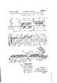
- Figs. 1 and 2 represent in side view and elevation the varioustools efiecting the perforations and cuts, in their places relatively to analready finished strip.
- Fig. 3 represents perspectively the junction of four strips, and
- Fig. l shows a card of matches manufactured by the process according to tire present invention.
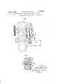
- Figs. 5 and 6 show the setting device infront and side view.
- Fig. 7 shows a spring-controlled pin of the setting-device.
- a cardboardband a is provided between the plates 2 and;10 by thecu-tters 3 Withparallel cuts which do not extend quite to tl e edge of the cardboardbands, so that at each-longitudinal edge there will still be left a holdingstrip 1a or 15.
- the cutters '8 cut out at one longitudinal side of the band the ends 1430f the. tongues subsequently carrying the match heads, an d at. the same time-the punches ,5 punch at; the rooftof the matches .30 holes- L7; in the-holdenstrip 15;, and the wide punch 7 punches out.
- Theqnanner inwvhichthese holes are utilizedfor the guiding, is illustrated in-perspect ve in Figure by Way of example for-the simultaneous guiding; of: four match bands which are to 'be guided' together with: a band intendedto form the bookcover.
- Theqnanner inwvhichthese holes are utilizedfor the guiding, is illustrated in-perspect ve in Figure by Way of example for-the simultaneous guiding; of: four match bands which are to 'be guided' together with: a band intendedto form the bookcover.
- the pin wheels 19, are of exactly the same construction and make the same movement, so that the pins of the wheels 19, 20
- the holes 17 of the upper bands a, I) always coincide therefore exactly with the holes 17 of the lower bands a1, 61, and the bands can therefore be for instance glued together exactly hole and hole.
- the glued togetherdouble match strips a, a1 and 6, 61 which travel next to each other, can further be connected, in amanner which need not be further described here, to a cover band 21 which is provided with advance holes 22 arranged at distance apart which correspond exactly tothe width of a. single match book.
- a feed roller 23 of the cover band 21 carries on the circumference pins 24, the distance between which corresponds to the distance between the holes 22, or to the width of a match book.
- the pins 24 of the adjustable roller 23 during its ro-' tation, engage with the holes 22 of the cover band 21, and thus bring about always an exact and uniform advance of the cover band.
- the match strips are moved in the manner already described by the pin wheels 19 and 20, the pins of which engage with the series of holes 17 of the match strips, the correct position of the match strips on the cover band 21 is ensured provided that the drives for the pin wheels 19 and 20 and for the roller 23 are properly connected together, so that this also ensures that during the subsequent cutting of the strips into books, the cuts will always be effected at the proper place.
- the guiding by holes and pins is required wherever it is a question of exact cooperation of tools with portions of the match strips to be treated.
- the setting device which is intended for bending the matches, before their dipping, alternately to opposite sides.
- the strip is moved above a receptacle 25 filled with the impregnating mass'for the tops of the matches between two wheels 26 tudinal direction.
- spring controlled pins (27) near the edge of these wheels. pins pressed by thesprings 31, project over the side walls of the wheels.
- cam 32 On the frame there is mounted a cam 32 upon which run the tops 28 of the spring controlled pins 27 while the corresponding wheel turns so that the spring-controlled pins are displaced in the wheel 26; the cam 32 rises obliquely from the right edge I to the edge II, then it does not alter its place up to the edge III and falls obliquely to the edge IV. Therefore the cam 32 has a trapezoid-like cross section.
- the setting device is followed by a feedconsisting of a sprocket wheel '33,the"pins of which engage with the 'holes 17-of the strips, in order to insure a perfectly regulated advance of the strip, so that the spring-controlled pins engage the matches exactly at" the-proper place.
- the single matches separated from each other by cuts, are attached at their bottom end to anarrow strip 15 of the material, of which they are made, and between each two matches 30, immediately above the root, is arranged a series of holes 17 in such a manner that they are situated between each two matches 30. Owing .to the provision of these holes 17, places of least resistance are produced at the root of the single matches, where they can be broken off.
- the perforations 17 can have any desired shape, but the round shape has proved best.
- the process described can be applied to any materials suitable for the manufacture of such matches, such as flat wood plates, cardboard, and the like.
- a machine for the manufacture of strip matches comprising means for transversely 4 Lemmas slitting said strip,-me ans for perforating said StIiPyfiijfiC-Qht the ends ofthe slits, anda plurality, of pin members cooperatingwith said perforations for positioning said strip With-respect to said perforating means.
- 4k- Almachine for the manufacture of strip 4 matches, comprising means for feeding aplilral-ity; of strips-to said machine, means for transversely slitting said strips, means for perforating said. strips, and ineansionisaid feeding. means for simultaneously engaging the-perforations on superposedstrips to ad- -vance said stripsv a predetermined distance.
Landscapes
- Engineering & Computer Science (AREA)
- Manufacturing & Machinery (AREA)
- Mechanical Engineering (AREA)
- Chemical & Material Sciences (AREA)
- Organic Chemistry (AREA)
- Perforating, Stamping-Out Or Severing By Means Other Than Cutting (AREA)
Description
April 1932- SHRAKIOWITZKY ET AL 1,854,063
OOK MATCHES FROM CONTINUOUS STRIPS PROCESS FOR THE MANUFACTURE OF B Original Filed Aug. 11. 1 2
s Shee ts-Sheet 1 Fig.3. 22s J v v I a /nyewfar- 4g; 11 s; A, 40
\ I all J 17 9 v 3 Sheets-Sheet 2 S. RAKOWITZKY ET AL Original Filed Aug. 11 1927 April-12, 1932.
mocEss FOR THE MANUFACTURE OF BOOK MATCHES FROM CONTINUOUS STRIPS April 1932- s. RAKOWITZKY ET AL 1,854,063
' PROCESS FOR THE MANUFACTURE, OF BOOK-MATCHES FROM CONTINUOUS STRIPS Original Filed Aug. 11. 1927 5 Sheets-Sheet 3 o 0O i c 327 27 g ,8
//7 Van 7 OI'IS s/man Eakaw/fiz/ and sc/; Qa o WI /Zk/ Patented Apr. 12, 1932 UNITED STATES PATENT oFFicej SELMAN RAKOWITZKY -AND HIRSCH RAKOWITZKY OF VIENNA, AUSTRIA rnocnss FOR THE anufacturer: ornoox MATCHES FROM con'rmuous s'rRIrs Application fiiki August 11, 1927, Seria1'No. 212,312, and in Austria May 1a, 1927. Renewed' September 4, 1931. Y i V Book matches which are manufactured in continuous strips or bands and in which the single matches are held together by'a strip of the material, are very largely used at present. Experience shows that in practical use,the' single matches are almost never completely detached at their roots, but-break off a little higher, owing towhich the length of the match is reduced, and irregular bits are left in the book.
It has been already proposed, for the .pur-
poseof facilitating the tearing off of the matches,"to weaken their connection to the strip of material by means of a notch. This notching has not, however, led to the desired result as'it leaves: between the match and the strip a b'ridge diflicult to break, in which the fibres lie very close together.
It is necessary to give the match, preferably V band, ortreated ina uniform manner, preferably made before the beginning of the process of manufacture, a shape that would eliminate the drawbacks above referred to, and at the same timeenable strips or booksof mzuzohes to be manufactured from one or more continuous bands in a. single operation.
In order always to ensure an easy breaking of]? of the matches at the root, the junction of the matches to the strip could be weakened by removing material atthat point. This is preferably doneby means of perforations,
theobject of which is to provide the points oflleast resistance and thereby insure the breaking off of the matches just at thoseexact points, so that the whole of the length of the match can be utilized, and no pieces are left in the book; moreover, these perforations which are made at the beginning of the process whichfinally results in the production offinished matches, constitute organs which, in cooperation with a suitably arranged machine, alford a guarantee for a perfect manufacture of finished match books or packets.
Incarrying-outthe process,the strip or a plurality of such bands to be of cardboard or the like,'are unwound from large reels or rolls and during the various operations required for the manufacture of books of matches, are guided in a suitable manner so that on the one handthe feed or 'ner if they are open even wheels described later advance of the band always remains the same forgiven operatlons or, when treating simultaneously several strips of matches, or such strips and a band of cardboard intended to of the single strips tothe extent of the width of one book match. I
It is obvious that the said perforations (17) can fulfill their object irrespectively of the point of the width of the match at which they are produced. In vie-w however of what has been stated in the beginning,it appears advisable to provide these perforations at the root of the matches so thatthey produce a weakening at the jointbetween the matches and their common holding strip (15), which weakening is of great importancefor the subsequent use ofthe matches.
The perforations provided at the root of the matches, will best fulfill their, object in subsequent use if they are arranged exactly between each two matches, in such 'a manner that each cutseparating the matches, is of exactly the same length, as owing to the'perforations provided, the matches can be torn off in a neat manner. It must be pointed out here that the perforations ,pIOVldeCl in the continuous band cannot fulfill their object of forming guide organs in a perfect man- 7 only at one side, as this affects the reliable guiding, by the pin on.- It is therefore inadvisable to remove a portion of the material between each two matches, at the point Where the'separation cut is made, whether such removal be efiected throughout the whole struction similar to provided for the guiding. Another drawback of any removal of material is also that the material is wasted, the cutting tools work in a more complicated manner, and a smaller number of matches can be produced during the same operation. of the machine.
The general construction of a machine for the manufacture of strips of matches or of books of matches containing such strips, in a" single operation, may be for instance such that the support for therolls of cardboard bands is adjoined bythe which cuts the single matches in the cardboard 'ban'ds. Then follows a araffinin device which if desired may be combinedwith aniimpregnating device. A. setting device which now follows,bends the matches'alternately'to different sides and prepares them for the clipping process which provides them withheads. After the band has been carried in long sinuous lines for the purpose of air drying, a device could be provided which glues 'tggether two bands of 'matches. carried one above the other,a1 1d at thesame time these two superposed bands can be brought to another cardboard band intended to form lIllQCOVQI. By means of a cutting device can then be produced sections or cuts, corresponding to t e width of the match book, namely in such a manner that the strips of matches which are now superposed, and the band supplying the cover, are cut simultaneously. The manner in which the match books are finished, is immaterialfor the invention. 1
It isc'lea-r that such a' machine, of a conthat just described by way of example, could work correctly only provided that the feed devices arranged between the single working devices give a perfectly regulatedor positive advance, as is the case when gear wheels are used, but not when friction wheels are used. Tlhiscan beobtained with exactness if, the perforations made in the cardboard band or hands are themselves arranged at a uniform distance apart. The pin wheels or the like engaging with these perforations, must then necessarily give an advance corresponding exactly to the distance between two such holes, that is to say to the width of one match.
In the accompanying drawings isdiagrammatic-ally shown a device for carrying out the process ofthe invention. Figs. 1 and 2 represent in side view and elevation the varioustools efiecting the perforations and cuts, in their places relatively to analready finished strip. Fig. 3 represents perspectively the junction of four strips, and Fig. l shows a card of matches manufactured by the process according to tire present invention. Figs. 5 and 6 show the setting device infront and side view. Fig. 7 shows a spring-controlled pin of the setting-device.
The manner in which the said holes or perpun-ch-ing device forations are to be produced, in diagrammatically illustrated by way of example in Figures 1 and 2. To a press plate 1 vertic.lly adjustable for instance by means of eccentrics not shown, is secured a plate 2 with parallel cutters 3 and further a plate 4 with perforating puIJS hBS 5, setting-v mandrels 6, a wide punch 7 and head cutters 8. A table 9 carries a plate 10 as counter-plate for th'ecutters 3, as well as 'a plate ll withholes for the guiding of the punches 5, 7 and 8. Moreover, to the press plate lis secured" an ejectordevice 12 which ejects the completely cut outtongues through a slot 13 of the table top.
On reaching the punchingdevice, a cardboardband a is provided between the plates 2 and;10 by thecu-tters 3 Withparallel cuts which do not extend quite to tl e edge of the cardboardbands, so that at each-longitudinal edge there will still be left a holdingstrip 1a or 15. After a further advance-of'the cardboard band or; bands, duringthe passage between the platese and 11, the cutters '8 cut out at one longitudinal side of the band the ends 1430f the. tongues subsequently carrying the match heads, an d at. the same time-the punches ,5 punch at; the rooftof the matches .30 holes- L7; in the-holdenstrip 15;, and the wide punch 7 punches out. an elongated hole 18, :Each-two ofsuch'elongated holes 18cmclose a. st rip of matches intended for amatch book.
he setting. .mandrels. 6 which are; ar-
ranged-on the left handside of the perforate ing punches 5 anda-re of the sameconstruction as the latter, only longer and with pointed ends, engageduring' theworkingistrokeof the punching device with the previously punched out holes. 1?? of the match strip or band and'br'ing itin-to the :correct position, so; that the, punching perforators 5 which come intoaction immediately; afterwards, punch-the holes 17in a, perfectly exact man'- neriand atthe correct distance apart. Any slight movement of the band that: maybenecessariy can beie'ffected by, the setting. mandrels 6,. as the band: is, not held fast before the punching devicebecomes operative, but is merely laterally guided.
The holes 17 providedin the described manner at proper intervals, :ar eutiliZed during the who-le' subsequent working operation for the guiding andadvancingof the band a,
owing to the -.engagement"with the saidhole's of pinsiof pin wheels or thelike.
Theqnanner inwvhichthese holes are utilizedfor the guiding, is illustrated in-perspect ve in Figure by Way of example for-the simultaneous guiding; of: four match bands which are to 'be guided' together with: a band intendedto form the bookcover. Each two strips. w and]; .or all and bl-arefa-rranged'here sideby side, whilst the stripsa and'b; or 'b and (U are situatedvabove each other, The
eagues two upper match strips a and I) pass overan upper pin wheel 19, and the lower match strips a1, 51 pass over a lower pin wheel 20.
The pin wheels 19, are of exactly the same construction and make the same movement, so that the pins of the wheels 19, 20
engage exactly with the holes 17 of the match strips, and all the match strips, (2, 6, a1, 61, are moved in a perfectly uniform manner. The holes 17 of the upper bands a, I) always coincide therefore exactly with the holes 17 of the lower bands a1, 61, and the bands can therefore be for instance glued together exactly hole and hole. The glued togetherdouble match strips a, a1 and 6, 61 which travel next to each other, can further be connected, in amanner which need not be further described here, to a cover band 21 which is provided with advance holes 22 arranged at distance apart which correspond exactly tothe width of a. single match book. A feed roller 23 of the cover band 21 carries on the circumference pins 24, the distance between which corresponds to the distance between the holes 22, or to the width of a match book. The pins 24 of the adjustable roller 23 during its ro-' tation, engage with the holes 22 of the cover band 21, and thus bring about always an exact and uniform advance of the cover band. As the match strips are moved in the manner already described by the pin wheels 19 and 20, the pins of which engage with the series of holes 17 of the match strips, the correct position of the match strips on the cover band 21 is ensured provided that the drives for the pin wheels 19 and 20 and for the roller 23 are properly connected together, so that this also ensures that during the subsequent cutting of the strips into books, the cuts will always be effected at the proper place.
For the part of the machine just described, the guiding by holes and pins is required wherever it is a question of exact cooperation of tools with portions of the match strips to be treated. Only by way of example may be mentioned the setting device which is intended for bending the matches, before their dipping, alternately to opposite sides. The strip is moved above a receptacle 25 filled with the impregnating mass'for the tops of the matches between two wheels 26 tudinal direction. In each wheel there are provided spring controlled pins (27) near the edge of these wheels. pins pressed by thesprings 31, project over the side walls of the wheels. On the frame there is mounted a cam 32 upon which run the tops 28 of the spring controlled pins 27 while the corresponding wheel turns so that the spring-controlled pins are displaced in the wheel 26; the cam 32 rises obliquely from the right edge I to the edge II, then it does not alter its place up to the edge III and falls obliquely to the edge IV. Therefore the cam 32 has a trapezoid-like cross section. The
alter "their in g device (Fig; 6),
in its longi- The tops 28 of these ..-Wheel are removed to the right side; JInithis way the matches are set-01f in alternate opposite directions: Thesetting-off of the matches is effected, as the strip is moved above the receptacle 25 as at this time the pins 27 do not places according to the form of the'cams" 32. i
The setting device is followed by a feedconsisting of a sprocket wheel '33,the"pins of which engage with the 'holes 17-of the strips, in order to insure a perfectly regulated advance of the strip, so that the spring-controlled pins engage the matches exactly at" the-proper place.
For the purpose of'exact guiding of the matchfstrips during the various working operations of the machine, it is in itself immaterial at which portion of the width of the bands the holes or'perforations 17 are provided. It is preferable however to arrange these perforations in the manner illustrated,
at the root of the matches, namely-in such a manner that the perforations are always situated between each two matches. As already stated, this provides the weakening of the joints of the matches to the holder part 15,,
facilitating the tearing olf of the single matches from the said holder, as points of least resistance are producedat'the root of the matches, so that the separation takes place easily and always at the root, owing to which the matches broken off, always have the same length, and no irregular bits are left in the book cover.
A card or strip of matches manufactured by the process described, is shown in Figure 4.
The single matches separated from each other by cuts, are attached at their bottom end to anarrow strip 15 of the material, of which they are made, and between each two matches 30, immediately above the root, is arranged a series of holes 17 in such a manner that they are situated between each two matches 30. Owing .to the provision of these holes 17, places of least resistance are produced at the root of the single matches, where they can be broken off. The perforations 17 can have any desired shape, but the round shape has proved best. The process described can be applied to any materials suitable for the manufacture of such matches, such as flat wood plates, cardboard, and the like.
What we'claim is: 1. A machine for the manufacture of strip matches, comprising means for transversely 4 Lemmas slitting said strip,-me ans for perforating said StIiPyfiijfiC-Qht the ends ofthe slits, anda plurality, of pin members cooperatingwith said perforations for positioning said strip With-respect to said perforating means.
3-; A-machinevas claimed in-clai-in 1, said perforations coinciding Wih the-end of each slit. J
4k- Almachine :for the manufacture of strip 4 matches, comprising means for feeding aplilral-ity; of strips-to said machine, means for transversely slitting said strips, means for perforating said. strips, and ineansionisaid feeding. means for simultaneously engaging the-perforations on superposedstrips to ad- -vance said stripsv a predetermined distance.
In testimony whereof We have signed our names to this specification.
SELMAN RAKOWITZKY. HIRSGH- RAKOWITZKY.
Publications (1)
| Publication Number | Publication Date |
|---|---|
| US1854063A true US1854063A (en) | 1932-04-12 |
Family
ID=3423667
Family Applications (1)
| Application Number | Title | Priority Date | Filing Date |
|---|---|---|---|
| US1854063D Expired - Lifetime US1854063A (en) | Ooooooooqoo |
Country Status (1)
| Country | Link |
|---|---|
| US (1) | US1854063A (en) |
-
0
- US US1854063D patent/US1854063A/en not_active Expired - Lifetime
Similar Documents
| Publication | Publication Date | Title |
|---|---|---|
| US3738889A (en) | Method of making a disposable filtering device | |
| US3075684A (en) | Easy to open carton | |
| US1340225A (en) | Method of cutting sheet material | |
| US2648380A (en) | Method of cutting web into strips | |
| US1705748A (en) | bridgman | |
| US1854063A (en) | Ooooooooqoo | |
| US2386147A (en) | Method and machine for punching out articles from strips | |
| US2163923A (en) | Partition fabricating machine | |
| US2376724A (en) | Method of cutting openings through a pile of sheets | |
| US2759402A (en) | Machine for removing waste slugs from carton blanks | |
| US2851933A (en) | Means for making paper box blanks in multiples | |
| KR101441442B1 (en) | Method for producing blisters, strips, pouches, trays for vials and the like | |
| US1992962A (en) | Method of producing scroll-edged metal blanks | |
| US1574481A (en) | Apparatus for and process of making pulley units | |
| US3304102A (en) | Data card | |
| US1957957A (en) | Tray making machine | |
| SE1650303A1 (en) | Machine and method for producing packaging inserts | |
| US1402261A (en) | Method of making boxes and box blanks | |
| US2852074A (en) | Means for making paper partitions | |
| US1927404A (en) | Wrapper nicking device | |
| US1949430A (en) | Method of forming scroll edge metal blanks | |
| US2022088A (en) | Method of | |
| US1813805A (en) | Manufacture from sheet metal of pointed fastening devices | |
| US1756257A (en) | Method of manufacturing fasteners | |
| US2093241A (en) | Machine for making match cards |