US1237130A - Spark-arrester. - Google Patents
Spark-arrester. Download PDFInfo
- Publication number
- US1237130A US1237130A US8359115A US8359115A US1237130A US 1237130 A US1237130 A US 1237130A US 8359115 A US8359115 A US 8359115A US 8359115 A US8359115 A US 8359115A US 1237130 A US1237130 A US 1237130A
- Authority
- US
- United States
- Prior art keywords
- casing
- container
- spark
- arrester
- stack
- Prior art date
- Legal status (The legal status is an assumption and is not a legal conclusion. Google has not performed a legal analysis and makes no representation as to the accuracy of the status listed.)
- Expired - Lifetime
Links
- 239000003818 cinder Substances 0.000 description 4
- 238000010276 construction Methods 0.000 description 3
- 239000000779 smoke Substances 0.000 description 3
- 239000007789 gas Substances 0.000 description 1
- 230000005484 gravity Effects 0.000 description 1
- 230000008676 import Effects 0.000 description 1
- 238000004519 manufacturing process Methods 0.000 description 1
- 229920000136 polysorbate Polymers 0.000 description 1
Images
Classifications
-
- B—PERFORMING OPERATIONS; TRANSPORTING
- B01—PHYSICAL OR CHEMICAL PROCESSES OR APPARATUS IN GENERAL
- B01D—SEPARATION
- B01D45/00—Separating dispersed particles from gases or vapours by gravity, inertia, or centrifugal forces
- B01D45/04—Separating dispersed particles from gases or vapours by gravity, inertia, or centrifugal forces by utilising inertia
- B01D45/08—Separating dispersed particles from gases or vapours by gravity, inertia, or centrifugal forces by utilising inertia by impingement against baffle separators
-
- Y—GENERAL TAGGING OF NEW TECHNOLOGICAL DEVELOPMENTS; GENERAL TAGGING OF CROSS-SECTIONAL TECHNOLOGIES SPANNING OVER SEVERAL SECTIONS OF THE IPC; TECHNICAL SUBJECTS COVERED BY FORMER USPC CROSS-REFERENCE ART COLLECTIONS [XRACs] AND DIGESTS
- Y10—TECHNICAL SUBJECTS COVERED BY FORMER USPC
- Y10S—TECHNICAL SUBJECTS COVERED BY FORMER USPC CROSS-REFERENCE ART COLLECTIONS [XRACs] AND DIGESTS
- Y10S55/00—Gas separation
- Y10S55/20—Spark arrester
Definitions
- the principal obj ectf ofthe invention isto ,provide'novel and eflicientmeans to prevent sp arks, Cinders orj flame from issuing from the stack. l
- Theinvention consists in the provision ormeans for deflecting an'dreceiving'all “cinders issuing from the stack, and 'it .is another object go'f.the 1invention "to so “con struct the device as” to permit of ready .re-
- a further object of the invention is to provide a device of thi-s'character"which is extremely simple in construction, cheap easy to manufacture and "which 'is thorf oughly reliable and eflicient in operation.
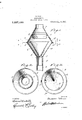
- the invention consists in the novel features of construction, combination and ar-- Fig. 2 is a transverse section on theline 2-2 of Fig. 1, a
- Fig. 8 is a similar view on the line 3-3 ⁇ of Fig. 1.
- 1 designates the smoke stack of a 1ocomotive,'tractor or the like, to whichthe improved spark arrester is adapted to be applied. 7
- the arrester in detail consists of a tube 2 of a diameter to be snugly received within the stack 1, being adapted for frictional engagement therewith, to prevent its removal therefrom and hold the same against lat eral movement.
- This tubular member is flared at itsupper'end, as at 3, to receive the lower open end of a substantially frustoconicallyshapedinyerted casing 4, rivets or especificationof i l'zetterswlia tent.
- Aug, 14 g1 9;1 7 Ap ueat bn fi ed'mreh njrerefsrieinoqssisaif 1 7 other suitable "faste'nirijg means pro- -v1ded for' securing the casing "to" the tube.
- this container is provided with a small .opening at its lower re stricted end for a purpose which will presently appear.
- a flange member 11 Secured to ing therefrom atanI angle'tothe side walls of the same is a flange member 11, the flange being of any desired length and terminating short" or. in spaced relation to the upper open end of the container 10 and having its lower edge disposed within the plane of the outer edge of the upper open end of the container.
- a sparkvarrester comprising a casing formed of two conical members separably connected at their base, an inverted conical container within the lower member, a plu- Copies of this patent may be obtained for five cents each, by addressing the Commissioner of Patents.
- a spark arrester comprising a casing formed of two inverted conical members separably joinedat their bases, an inverted conical container within the lower member spaced from the sides thereof, a plurality of U-shaped resilient strips between the containervand thelower member, the arms of which extend upwardly and outwardly, one arm of each strip being fastened to the lower member while the other arms are free j DELBERT WELGH.
Landscapes
- Chemical & Material Sciences (AREA)
- Chemical Kinetics & Catalysis (AREA)
- Catching Or Destruction (AREA)
Description
D. WELCH.
v SPARK ARRESTER. 1 APPLICATION HLED MAR. 1|, 1916.
1 ,2 37, 1 Patented Aug. 14, 1917.
INVENTOR DELBERT WE LOH ATTORNEY To all whomit'may comm-- nnmann'r wnmn on znnna imnsasii I i HSBA'BK-ARRESEEERH 1 Be it' known that l, "DEILBERT Wisnori, a citizen of'the United States, residing {at Zenda, in the county of 'Kingman and'Stat-e of Kansas, have invented certain "new and useful Improvements .in 'Spark-Arresters, of I which thefollowing is a specification This invention relates ,to: spark arresters for smoke'stac'ks of various descriptions, and is especially adapted for usein connection withlocomotives ortractor's.
The principal obj ectf ofthe invention isto ,provide'novel and eflicientmeans to prevent sp arks, Cinders orj flame from issuing from the stack. l
Theinvention consists in the provision ormeans for deflecting an'dreceiving'all "cinders issuing from the stack, and 'it .is another object go'f.the 1invention "to so "con struct the device as" to permit of ready .re-
moval of the cinders from the container.
A further object of the invention is to provide a device of thi-s'character"which is extremely simple in construction, cheap easy to manufacture and "which 'is thorf oughly reliable and eflicient in operation.
With the foregoing and other'objects in view, the invention consists in the novel features of construction, combination and ar-- Fig. 2 is a transverse section on theline 2-2 of Fig. 1, a
Fig. 8 is a similar view on the line 3-3} of Fig. 1.
Referring to the drawings by numerals,
wherein is illustrated the preferred embodiment of my invention, 1 designates the smoke stack of a 1ocomotive,'tractor or the like, to whichthe improved spark arrester is adapted to be applied. 7
The arrester in detail consists of a tube 2 of a diameter to be snugly received within the stack 1, being adapted for frictional engagement therewith, to prevent its removal therefrom and hold the same against lat eral movement. This tubular member is flared at itsupper'end, as at 3, to receive the lower open end of a substantially frustoconicallyshapedinyerted casing 4, rivets or especificationof i l'zetterswlia tent. Aug, 14 g1 9;1 7 Ap ueat bn fi ed'mreh njrerefsrieinoqssisaif 1 7 other suitable "faste'nirijg means pro- -v1ded for' securing the casing "to" the tube.
- The ng 4 s 9 any'desired-lengthwand I F ji's ad apted to ha' e' hingetlly connected" therewith,";-as-at -5,'*a ,isecond' casing of; substanti-ally the same 'sil'ae {and-shape as the "first un-eiitioned R'ca'sin g, "the" [larger i open ends of ahe easiags being adapted "for aabutting relation sothat ,a substantiallyinclosednous ond casingbiis open 'and is provided *withia relati-vely short tubular mem-ber which is secured'thereimin anysuitable manner. p
. Secured t-o the im ter face-of the '--Inember 4 are a plurality of spaced "yiel'dable' strips latio'n with the tapered walls ofithis casing 7'0 '8 which "extend in :sub'stantially parallel *reand terminate at-their upperends'dn inwardly bent portions 9 which aredisposed open e'nd ettheea ing; Thesemembers-"are' adaptedto "support faminvertedfitubul-ar' cone shaped memb r' er container *10, the side esiibstantially ,in;-a1inement with: i the upper walls thereof being adapted for engagement with 'the 'bo dy portion "df th'e tstrips"'j8;iwliile "theu'pper edge. thereof is adapted to be engaged by the inwardly extending portions 9 so that the same is held'rigidly within the.
casing. Preferably, this container is provided with a small .opening at its lower re stricted end for a purpose which will presently appear. Secured to ing therefrom atanI angle'tothe side walls of the same is a flange member 11, the flange being of any desired length and terminating short" or. in spaced relation to the upper open end of the container 10 and having its lower edge disposed within the plane of the outer edge of the upper open end of the container. I
From the constructiondescribed, it will the upper casing 6 anddependbe noted that upon swinging of the upper casing 6 to anopen position relatively to the casing 4 the strips I 8y may be swung out;
wardly todisengage the portions 9 from the upper end of the container 10 to permit of v its ready removal. When the upper casing is in a closed position it will be noted that sparks, cinders or the like issuing from the tween the walls of the container 10 and the casing 4=,thence upwardly and between the adjacent walls of the casing 6 and flange 11. AS S0011 asthe" force with which they stack 1 will pass through the tube .2 beare driven from the stack by the exhaust from the engine cylinder is overcome they will be caused to fall by gravity to the container 10 where they will be received and atmosphere, but a clear passage will be provided through the tube 7 for all gases, smoke or the like. i I
It is desirable to provide means to retain the casings 4, and 6 in a closed position. I accomplish this by providing upon the casing 4c a keeper 12 and by providing upon the casing 6 a pivoted hasp 13 for engagement therewith. 4
From the, foregoing description taken in connection with the accompanying drawings it is thought that the construction and operation of the improved sparkarrester will be clearly understood and while I have here in shown and described one specific, embodiment of my invention I do not wish to be limited thereto except for such limitations as the claims may import.
I claim:
I. A sparkvarrester comprising a casing formed of two conical members separably connected at their base, an inverted conical container within the lower member, a plu- Copies of this patent may be obtained for five cents each, by addressing the Commissioner of Patents.
rality of resilient strips fastened to the lower member of the casing and extending upwardly and outwardly at an angle to serve as a support for said container, said strips each having a finger on its upper end to overlie the top of the container and hold the same in place, said fingers adapted to be disconnected from the container by springing said strips outwardly.
2. A spark arrester comprising a casing formed of two inverted conical members separably joinedat their bases, an inverted conical container within the lower member spaced from the sides thereof, a plurality of U-shaped resilient strips between the containervand thelower member, the arms of which extend upwardly and outwardly, one arm of each strip being fastened to the lower member while the other arms are free j DELBERT WELGH. Witnesses a W. E. Pmnson,
WILLIAM STEOKER.
Washington, D. C. 7
Priority Applications (1)
| Application Number | Priority Date | Filing Date | Title |
|---|---|---|---|
| US8359115A US1237130A (en) | 1915-03-11 | 1915-03-11 | Spark-arrester. |
Applications Claiming Priority (1)
| Application Number | Priority Date | Filing Date | Title |
|---|---|---|---|
| US8359115A US1237130A (en) | 1915-03-11 | 1915-03-11 | Spark-arrester. |
Publications (1)
| Publication Number | Publication Date |
|---|---|
| US1237130A true US1237130A (en) | 1917-08-14 |
Family
ID=3304949
Family Applications (1)
| Application Number | Title | Priority Date | Filing Date |
|---|---|---|---|
| US8359115A Expired - Lifetime US1237130A (en) | 1915-03-11 | 1915-03-11 | Spark-arrester. |
Country Status (1)
| Country | Link |
|---|---|
| US (1) | US1237130A (en) |
-
1915
- 1915-03-11 US US8359115A patent/US1237130A/en not_active Expired - Lifetime
Similar Documents
| Publication | Publication Date | Title |
|---|---|---|
| US914571A (en) | Insect-trap. | |
| US1237130A (en) | Spark-arrester. | |
| US1128248A (en) | Hose-holder. | |
| US1588781A (en) | Toothbrush protector | |
| US1008323A (en) | Anchoring tent-pin. | |
| US851012A (en) | Railway signal-flag. | |
| US1110383A (en) | Condiment-holder. | |
| US952715A (en) | Door-catch. | |
| US833714A (en) | Fruit-clipper. | |
| US411327A (en) | Spark-arrester | |
| US571131A (en) | Lamp-chimney protector | |
| US1194954A (en) | Impalement-trap | |
| US1297335A (en) | Protector for gas mantles and lamps. | |
| US1323509A (en) | Fly catcher and swatter | |
| US886642A (en) | Trousers-holder. | |
| US983122A (en) | Attachment for pipes. | |
| US1224031A (en) | Milk-ticket holder and protector. | |
| US1225971A (en) | Insect-beater. | |
| US799595A (en) | Fence-post and securing device. | |
| US621379A (en) | Munroe vaughn siioffner | |
| US596334A (en) | Animal-trap | |
| US299628A (en) | Heney s | |
| US1135052A (en) | Mole-trap. | |
| US352485A (en) | Spark-arrester | |
| US961110A (en) | Cigar-clipper. |