US12343031B2 - Treatment tool for endoscope - Google Patents
Treatment tool for endoscope Download PDFInfo
- Publication number
- US12343031B2 US12343031B2 US17/650,344 US202217650344A US12343031B2 US 12343031 B2 US12343031 B2 US 12343031B2 US 202217650344 A US202217650344 A US 202217650344A US 12343031 B2 US12343031 B2 US 12343031B2
- Authority
- US
- United States
- Prior art keywords
- bendable
- operating
- wire
- endoscope
- slider
- Prior art date
- Legal status (The legal status is an assumption and is not a legal conclusion. Google has not performed a legal analysis and makes no representation as to the accuracy of the status listed.)
- Active, expires
Links
Images




Classifications
-
- A—HUMAN NECESSITIES
- A61—MEDICAL OR VETERINARY SCIENCE; HYGIENE
- A61B—DIAGNOSIS; SURGERY; IDENTIFICATION
- A61B17/00—Surgical instruments, devices or methods
- A61B17/28—Surgical forceps
- A61B17/29—Forceps for use in minimally invasive surgery
-
- A—HUMAN NECESSITIES
- A61—MEDICAL OR VETERINARY SCIENCE; HYGIENE
- A61B—DIAGNOSIS; SURGERY; IDENTIFICATION
- A61B17/00—Surgical instruments, devices or methods
- A61B17/28—Surgical forceps
- A61B17/29—Forceps for use in minimally invasive surgery
- A61B17/2909—Handles
-
- A—HUMAN NECESSITIES
- A61—MEDICAL OR VETERINARY SCIENCE; HYGIENE
- A61B—DIAGNOSIS; SURGERY; IDENTIFICATION
- A61B17/00—Surgical instruments, devices or methods
- A61B17/00234—Surgical instruments, devices or methods for minimally invasive surgery
- A61B2017/00238—Type of minimally invasive operation
- A61B2017/00269—Type of minimally invasive operation endoscopic mucosal resection EMR
-
- A—HUMAN NECESSITIES
- A61—MEDICAL OR VETERINARY SCIENCE; HYGIENE
- A61B—DIAGNOSIS; SURGERY; IDENTIFICATION
- A61B17/00—Surgical instruments, devices or methods
- A61B17/00234—Surgical instruments, devices or methods for minimally invasive surgery
- A61B2017/00292—Surgical instruments, devices or methods for minimally invasive surgery mounted on or guided by flexible, e.g. catheter-like, means
- A61B2017/003—Steerable
- A61B2017/00305—Constructional details of the flexible means
- A61B2017/00309—Cut-outs or slits
-
- A—HUMAN NECESSITIES
- A61—MEDICAL OR VETERINARY SCIENCE; HYGIENE
- A61B—DIAGNOSIS; SURGERY; IDENTIFICATION
- A61B17/00—Surgical instruments, devices or methods
- A61B17/00234—Surgical instruments, devices or methods for minimally invasive surgery
- A61B2017/00292—Surgical instruments, devices or methods for minimally invasive surgery mounted on or guided by flexible, e.g. catheter-like, means
- A61B2017/003—Steerable
- A61B2017/00305—Constructional details of the flexible means
- A61B2017/00314—Separate linked members
-
- A—HUMAN NECESSITIES
- A61—MEDICAL OR VETERINARY SCIENCE; HYGIENE
- A61B—DIAGNOSIS; SURGERY; IDENTIFICATION
- A61B17/00—Surgical instruments, devices or methods
- A61B2017/00367—Details of actuation of instruments, e.g. relations between pushing buttons, or the like, and activation of the tool, working tip, or the like
-
- A—HUMAN NECESSITIES
- A61—MEDICAL OR VETERINARY SCIENCE; HYGIENE
- A61B—DIAGNOSIS; SURGERY; IDENTIFICATION
- A61B17/00—Surgical instruments, devices or methods
- A61B2017/00367—Details of actuation of instruments, e.g. relations between pushing buttons, or the like, and activation of the tool, working tip, or the like
- A61B2017/00389—Button or wheel for performing multiple functions, e.g. rotation of shaft and end effector
-
- A—HUMAN NECESSITIES
- A61—MEDICAL OR VETERINARY SCIENCE; HYGIENE
- A61B—DIAGNOSIS; SURGERY; IDENTIFICATION
- A61B17/00—Surgical instruments, devices or methods
- A61B17/28—Surgical forceps
- A61B17/29—Forceps for use in minimally invasive surgery
- A61B2017/2901—Details of shaft
- A61B2017/2905—Details of shaft flexible
-
- A—HUMAN NECESSITIES
- A61—MEDICAL OR VETERINARY SCIENCE; HYGIENE
- A61B—DIAGNOSIS; SURGERY; IDENTIFICATION
- A61B17/00—Surgical instruments, devices or methods
- A61B17/28—Surgical forceps
- A61B17/29—Forceps for use in minimally invasive surgery
- A61B17/2909—Handles
- A61B2017/2912—Handles transmission of forces to actuating rod or piston
- A61B2017/2919—Handles transmission of forces to actuating rod or piston details of linkages or pivot points
-
- A—HUMAN NECESSITIES
- A61—MEDICAL OR VETERINARY SCIENCE; HYGIENE
- A61B—DIAGNOSIS; SURGERY; IDENTIFICATION
- A61B17/00—Surgical instruments, devices or methods
- A61B17/28—Surgical forceps
- A61B17/29—Forceps for use in minimally invasive surgery
- A61B17/2909—Handles
- A61B2017/2912—Handles transmission of forces to actuating rod or piston
- A61B2017/2919—Handles transmission of forces to actuating rod or piston details of linkages or pivot points
- A61B2017/292—Handles transmission of forces to actuating rod or piston details of linkages or pivot points connection of actuating rod to handle, e.g. ball end in recess
-
- A—HUMAN NECESSITIES
- A61—MEDICAL OR VETERINARY SCIENCE; HYGIENE
- A61B—DIAGNOSIS; SURGERY; IDENTIFICATION
- A61B17/00—Surgical instruments, devices or methods
- A61B17/28—Surgical forceps
- A61B17/29—Forceps for use in minimally invasive surgery
- A61B17/2909—Handles
- A61B2017/2912—Handles transmission of forces to actuating rod or piston
- A61B2017/2919—Handles transmission of forces to actuating rod or piston details of linkages or pivot points
- A61B2017/2922—Handles transmission of forces to actuating rod or piston details of linkages or pivot points toggle linkages
-
- A—HUMAN NECESSITIES
- A61—MEDICAL OR VETERINARY SCIENCE; HYGIENE
- A61B—DIAGNOSIS; SURGERY; IDENTIFICATION
- A61B17/00—Surgical instruments, devices or methods
- A61B17/28—Surgical forceps
- A61B17/29—Forceps for use in minimally invasive surgery
- A61B17/2909—Handles
- A61B2017/2912—Handles transmission of forces to actuating rod or piston
- A61B2017/2923—Toothed members, e.g. rack and pinion
-
- A—HUMAN NECESSITIES
- A61—MEDICAL OR VETERINARY SCIENCE; HYGIENE
- A61B—DIAGNOSIS; SURGERY; IDENTIFICATION
- A61B17/00—Surgical instruments, devices or methods
- A61B17/28—Surgical forceps
- A61B17/29—Forceps for use in minimally invasive surgery
- A61B2017/2926—Details of heads or jaws
- A61B2017/2932—Transmission of forces to jaw members
- A61B2017/2944—Translation of jaw members
Definitions
- ESD endoscopic submucosal dissection
- An interior wall such as the esophagus, stomach, and large intestine to which ESD is applied consists of three layers including a mucous membrane layer, a submucosal layer, and a muscular layer.
- a lesion part of the mucous membrane layer including the submucosal layer is peeled off, and it is also possible to collectively excise, for example, a relatively large lesion part which exceeds 2 cm.
- the treatment tool for an endoscope described in JP2002-330973A can only pull the lesion part gripped by the forcep member in the axial direction of the sheath with an operation of the treatment tool alone.
- a bending operation of the endoscope is necessary to lift the lesion part, and the visual field of the endoscope moves in response to the bending operation of the endoscope, thereby increasing the difficulty of treatment.
- the present invention is devised in view of the circumstances described above, and an object thereof is to provide a treatment tool for an endoscope that can easily perform gripping of a lesion part and lifting of the gripped lesion part with an operation of the treatment tool alone.
- a treatment tool for an endoscope comprising an insertion part that has a distal end part, which is provided with an openable and closable grip part, and a bendable part, which is provided adjacent to the distal end part and is bendable, and that is insertable into a body, an operating part into which an operation of closing the grip part and an operation of bending the bendable part are input, and a transmitting part that transmits an operation of the operating part to the grip part and the bendable part.
- the transmitting part has a first transmitting member that extends from the grip part toward the operating part, is moved in a first direction, which is an operating part side or a distal end part side, based on the operation of the operating part, and closes the grip part by moving in the first direction, a second transmitting member that extends from the bendable part toward the operating part, is moved in the first direction based on the operation of the operating part, and bends the bendable part by moving in the first direction, a first movable body that is connected to the first transmitting member and is moved in the first direction based on the operation of the operating part, and a second movable body that is connected to the second transmitting member and is moved in the first direction based on the operation of the operating part.
- the first movable body is moved in the first direction
- the second movable body is moved in the first direction after start of a movement of the first movable body.
- the treatment tool for an endoscope that can easily perform gripping of a lesion part and lifting of the gripped lesion part with an operation of the treatment tool alone.
- FIG. 1 is a view showing an example of an endoscope system, which is for describing Embodiment 1 of the present invention.
- FIG. 2 is a view showing an example of a treatment tool for an endoscope, which is for describing Embodiment 1 of the present invention.
- FIG. 3 is a view showing a grip part of the treatment tool for an endoscope of FIG. 2 .
- FIG. 4 is a view showing an operation of the grip part of FIG. 3 .
- FIG. 6 is a view showing a bendable part of the treatment tool for an endoscope of FIG. 2 .
- FIG. 7 is a view showing a cross section of the bendable part of FIG. 6 .
- FIG. 8 is a view showing an operation of the bendable part of FIG. 6 .
- FIG. 9 is a view showing an operating part of the treatment tool for an endoscope of FIG. 2 .
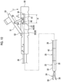
- FIG. 10 is a view showing a transmitting part of the treatment tool for an endoscope of FIG. 2 .
- FIG. 11 is a view showing an operation of the transmitting part of FIG. 10 .
- FIG. 29 is a view showing another example of the treatment tool for an endoscope, which is for describing Embodiment 1 of the present invention.
- FIG. 44 is a view showing Modification Example 3 of the operating part of the treatment tool for an endoscope, which is for describing Embodiment 2 of the present invention.
- FIG. 45 is a view showing Modification Example 4 of the operating part of the treatment tool for an endoscope, which is for describing Embodiment 2 of the present invention.
- FIG. 49 is a view showing Modification Example 6 of the operating part of the treatment tool for an endoscope, which is for describing Embodiment 2 of the present invention.
- FIG. 50 is a view showing operations of the grip part 24 and the bendable part 25 of FIG. 49 .
- FIG. 1 shows an example of an endoscope system for describing Embodiment 1 of the present invention.
- An endoscope system 1 comprises an endoscope 2 , a light source device 3 , and a processor 4 .
- the endoscope 2 has an endoscope insertion part 6 that is inserted into a subject, an endoscope operating part 7 that is connected to the endoscope insertion part 6 , and a universal cord 8 that extends from the endoscope operating part 7 .
- the endoscope insertion part 6 is composed of an endoscope distal end part 10 , an endoscope bendable part 11 that is connected to the endoscope distal end part 10 , and an endoscope soft portion 12 that connects the endoscope bendable part 11 to the endoscope operating part 7 .
- An imaging apparatus including an imaging element is mounted on the endoscope distal end part 10 .
- the endoscope bendable part 11 is configured to be bendable, and the bending of the endoscope bendable part 11 is operated by the endoscope operating part 7 .
- the endoscope soft portion 12 is soft enough to be deformable along a shape of an insertion passage in the subject.
- the endoscope operating part 7 is provided with an operation button for operating image pick-up using the imaging apparatus and an operation knob for operating the bending of the endoscope bendable part 11 .
- the endoscope operating part 7 is provided with a first treatment tool insertion opening 13 and a second treatment tool insertion opening 15 , into which the treatment tool for an endoscope is insertable.
- a first treatment tool channel 14 that reaches the endoscope distal end part 10 from the first treatment tool insertion opening 13 and is open to an edge surface of the endoscope distal end part 10 and a second treatment tool channel 16 that reaches the endoscope distal end part 10 from the second treatment tool insertion opening 15 and is open to the edge surface of the endoscope distal end part 10 are provided.
- a light guide and a cable are provided inside the endoscope insertion part 6 , the endoscope operating part 7 , and the universal cord 8 .
- a connector 9 is provided at a terminal of the universal cord 8 .
- the endoscope 2 is connected to the light source device 3 and the processor 4 via the connector 9 .
- Illumination light generated by the light source device 3 is guided to the endoscope distal end part 10 via the light guide and is emitted from the endoscope distal end part 10 .
- operating power of the imaging element, a control signal for driving the imaging element, and an image signal output from the imaging element are transmitted between the processor 4 and the imaging apparatus via the cable.
- the processor 4 processes the input image signal to generate image data of an observation site in the subject, displays the generated image data on a monitor 5 , and records the generated image data.
- FIG. 2 shows an example of the treatment tool for an endoscope, which is for describing Embodiment 1 of the present invention.
- a treatment tool for an endoscope 20 comprises an insertion part 21 that can be inserted into the first treatment tool channel 14 (see FIG. 1 ) and an operating part 22 .
- the insertion part 21 has a distal end part 23 at which an openable and closable grip part 24 is provided, a bendable part 25 that is provided adjacent to an operating part side of the distal end part 23 and is bendable, and a soft portion 26 that connects the bendable part 25 to the operating part 22 .
- the insertion part 21 is inserted in the first treatment tool channel 14
- the distal end part 23 and the bendable part 25 protrude from the edge surface of the endoscope distal end part 10 (see FIG. 1 )
- the soft portion 26 is accommodated in the first treatment tool channel 14 .
- the soft portion 26 accommodated in the first treatment tool channel 14 is soft enough to be deformable along the shape of the insertion passage in the subject.
- the soft portion 26 can be configured, for example, such that an outer periphery of a screw pipe, which is formed by spirally winding a metal strip plate material, is covered with a mesh pipe formed by braiding a metal wire and an outer periphery of the mesh pipe is covered with a resin outer coat.
- the treatment tool for an endoscope 20 further comprises a transmitting part 27 that transmits the operations of the operating part 22 to the grip part 24 and the bendable part 25 .
- the transmitting part 27 has a first transmitting member 28 that extends from the grip part 24 toward the operating part 22 and a second transmitting member 29 that extends from the bendable part 25 toward the operating part 22 .
- the first transmitting member 28 and the second transmitting member 29 are accommodated inside the soft portion 26 .
- the closing operation input into the operating part 22 is transmitted to the grip part 24 via the first transmitting member 28
- the bending operation input into the operating part 22 is transmitted to the bendable part 25 via the second transmitting member 29 .
- FIGS. 3 and 4 show the grip part 24 .
- the grip part 24 has a pair of grip claws 30 , a pair of link members 31 , and a support 32 that supports the pair of grip claws 30 so as to be movable rotationally.
- the pair of grip claws 30 are disposed to intersect each other, and a pin 33 is provided to penetrate an intersecting portion of the pair of grip claws 30 .
- the pair of grip claws 30 are movable rotationally about the pin 33 which is a rotational movement shaft, and the pin 33 is fixed to the support 32 .
- a distal end part of each of the pair of link members 31 is connected to a proximal end part of each of the pair of grip claws 30 so as to be movable rotationally.
- a proximal end part of each of the pair of link members 31 is disposed to intersect each other, and a pin 34 is provided to penetrate an intersecting portion of the pair of link members 31 .
- the pair of link members 31 are movable rotationally about the pin 34 which is a rotational movement shaft, and the pin 34 is movable to increase or decrease a distance to the pin 33 instead of being fixed to the support 32 .
- one wire 35 is used in the present example, and a distal end part of the wire 35 is connected to the pin 34 .
- the wire 35 is pulled to an operating part 22 side based on the operation of the operating part 22 .
- movement of the wire 35 pulling to the operating part 22 side is defined as a movement in an A-direction, and pushing out to a distal end part 23 side is defined as a movement in a B-direction.
- FIG. 3 shows a state where the wire 35 is pushed out to the distal end part 23 side, and the distal end parts of the pair of grip claws 30 are open.
- the wire 35 By moving the wire 35 in the A-direction (first direction) based on an operation of the operating part 22 , the distal end parts of the pair of grip claws 30 are closed as shown in FIG. 4 .
- the wire 35 in the B-direction (second direction) by moving the wire 35 in the B-direction (second direction) in a state where the distal end parts of the pair of grip claws 30 are closed, the distal end parts of the pair of grip claws 30 are opened.
- FIGS. 6 to 8 show the bendable part 25 .
- FIGS. 18 to 21 show a treatment method for ESD as an example of a treatment method using the treatment tool for an endoscope 20 .
- the grip part 24 is closed based on an operation of the operating part 22 , and the lesion part LA is gripped by the grip part 24 . Then, after the lesion part LA is gripped by the grip part 24 , the bendable part 25 is bent based on an operation of the operating part 22 as shown in FIG. 20 . Accordingly, the grip part 24 is erected, and the lesion part LA gripped by the grip part 24 is lifted.
- a high-frequency forcep 90 is inserted into the second treatment tool channel 16 of the endoscope 2 , and the high-frequency forcep 90 protrudes from the edge surface of the endoscope distal end part 10 as shown in FIG. 21 . Then, a lower part of the lesion part LA is incised by the high-frequency forcep 90 .
- the other endoscope treatment tool used in combination with the treatment tool for an endoscope 20 is selected as appropriate according to treatment, and is not limited to the high-frequency forcep 90 .
- the other endoscope treatment tool include incision tools, such as high-frequency forceps and high-frequency knives, hemostatic tools, such as bipolar hemostatic forceps and clips, injection needles, and collection nets.
- the gripping of the lesion part LA by closing the grip part 24 and the lifting of the lesion part LA by bending the bendable part 25 are performed only by the operation of the operating part 22 as described above. Further, in a case where the grip part 24 is closed, the bendable part 25 is maintained in a linear shape, and a relative movement between the grip part 24 and the lesion part LA is prevented. Accordingly, the gripping of the lesion part LA and the lifting of the gripped lesion part LA can be easily performed with an operation of the treatment tool for an endoscope 20 alone.
- the wire 35 is moved in the A-direction, and the grip part 24 is closed. Then, after the grip part 24 is closed, the wire 42 is moved in the A-direction, and the bendable part 25 is bent in the C-direction. In this case, the wire 35 is also moved in the A-direction.
- the wire 35 is disposed on the bent inner diameter side in the bending of the bendable part 25 in the C-direction and a length on the bent inner diameter side is reduced with the bending, the movement of the wire 35 in the A-direction is offset. Therefore, an increase in a gripping force of the grip part 24 is prevented, and the lesion part LA is not excessively compressed.
- the wire 35 may be disposed on the bent outer diameter side in the bending of the bendable part 25 in the C-direction, or may be disposed on the bent neutral plane S of the bendable part 25 .
- the wire 35 for closing the grip part 24 is moved in the same A-direction as the wire 42 , prior to the wire 42 for bending the bendable part 25 in the C-direction. In this case, friction can occur between the wire 35 and the bendable part 25 . In a case where the wire 35 is disposed on the same bent inner diameter side of the bendable part 25 as the wire 42 , there is a possibility that the bendable part 25 is bent in the C-direction due to the friction of the wire 35 and the grip part 24 which is closed to grip the lesion part LA is separated from the lesion part LA.
- the grip part 24 is pressed against the lesion part LA as the bendable part 25 is bent in the D-direction opposite to the C-direction even though the bendable part 25 is bent due to the friction of the wire 35 .
- the wire 35 is disposed on the bent neutral plane S of the bendable part 25 , the bending of the bendable part 25 caused by the friction of the wire 35 is further prevented.
- the bendable part 25 may be configured to be not bendable in the D-direction. In this case, the bending of the bendable part 25 caused by the friction of the wire 35 is reliably prevented.
- the bendable part 25 is bendable only in the C-direction, in which the gap GB is narrowed, and is not bendable in the D-direction opposite to the C-direction.
- the first portion 40 A of the cyclic member 40 is positioned on the bent outer diameter side, and the second portion 40 B is positioned on the bent inner diameter side.
- the first guide 43 that holds the wire 35 which is the first transmitting member 28 is provided at the first portion 40 A, and the wire 35 is disposed on the bent outer diameter side.
- the second guide 44 that holds the wire 42 which is the second transmitting member 29 is provided at the second portion 40 B, and the wire 42 is disposed on the bent inner diameter side.
- the gap GB is narrowed as the wire 42 is moved in the A-direction, and thus the bendable part 25 is bent in the C-direction.
- the bendable part 25 is bent in the C-direction opposite to the D-direction, but the bendable part 25 is not bendable in the D-direction.
- the wire 35 is moved in the A-direction prior to the wire 42 , and in a case where the grip part 24 is closed, the bendable part 25 is reliably maintained in a linear shape. Accordingly, a relative movement between the grip part 24 and the lesion part LA gripped by the grip part 24 is prevented, and the gripping of the lesion part LA becomes even easier.
- the wire 35 may be disposed on the bent neutral plane S.
- the first guide 43 holding the wire 35 is provided, for example, at an end part of the pin 41 .
- the lesion part LA can be more firmly gripped due to an increase in the gripping force of the grip part 24 , but it is preferable that at least a part of the wire 35 in a longitudinal direction is configured to be flexible from a perspective of reducing compression with respect to the lesion part LA.
- a flexible part 36 which is formed by winding a part of the wire 35 in the longitudinal direction in a coil shape may be provided at the wire 35 .
- an elastic member such as rubber may be provided at a part of the wire 35 in the longitudinal direction.
- the wire 35 may be formed of a material having elasticity, such as a braided wire.
- a treatment tool for an endoscope 120 shown in FIGS. 25 and 26 is configured such that the bendable part is bendable in one direction and is not bendable in an opposite direction.
- the treatment tool for an endoscope 120 and the treatment tool for an endoscope 20 described above are different from each other only in terms of the configuration of the bendable part. Thus, common elements will be assigned with common reference numerals, and description thereof will be omitted.
- An insertion part 121 of the treatment tool for an endoscope 120 comprises the distal end part 23 , the bendable part 125 , and the soft portion 26 .
- the bendable part 125 has a plurality of cyclic portions 140 arranged in an axial direction of the insertion part 121 and one or more connecting portions 141 that connect two cyclic portions 140 adjacent to each other.
- the cyclic portions 140 and the connecting portions 141 are formed integrally with each other.
- the connecting portions 141 are formed in an arc shape that is concave to a central axis side of the insertion part 121 .
- the connecting portion 141 having an arc-shaped cross section is capable of only bending a concave surface inward of bending the concave surface inward and bending the concave surface outward. Therefore, the bendable part 125 is bendable only in the C-direction, in which the gap GB is narrowed, with the bending of the concave surface of the connecting portion 141 inward, and is not bendable in the D-direction opposite to the C-direction.
- the bent neutral plane S of the bendable part 125 passes through a circumferential middle portion of each of the plurality of connecting portions 141 arranged in the axial direction of the insertion part 121 .
- the wire 42 which is the second transmitting member 29 is disposed on the bent inner diameter side in the bending of the bendable part 125 in the C-direction.
- the gap GB is narrowed as the wire 42 is moved in the A-direction, and thus the bendable part 125 is bent in the C-direction.
- the wire 35 which is the first transmitting member 28 is disposed on the bent neutral plane S of the bendable part 125 . Since the bendable part 125 is not bendable in the D-direction opposite to the C-direction, based on an operation of the operating part 22 , the wire 35 is moved in the A-direction prior to the wire 42 , and in a case where the grip part 24 is closed, the bendable part 125 is reliably maintained in a linear shape. Accordingly, a relative movement between the grip part 24 and the lesion part LA gripped by the grip part 24 is prevented, and the gripping of the lesion part LA becomes even easier.
- a treatment tool for an endoscope 220 shown in FIGS. 27 and 28 is also configured such that the bendable part is bendable in one direction and is not bendable in an opposite direction.
- the treatment tool for an endoscope 220 and the treatment tool for an endoscope 20 described above are different from each other only in terms of the configuration of the bendable part. Thus, common elements will be assigned with common reference numerals, and description thereof will be omitted.
- An insertion part 221 of the treatment tool for an endoscope 220 comprises the distal end part 23 , a bendable part 225 , and the soft portion 26 .
- the bendable part 225 has a tubular member 240 and a restraining member 241 .
- the tubular member 240 is bent in the C-direction about the bending central axis X parallel to the opening and closing direction of the pair of grip claws 30 of the distal end part 23 , and is elastically deformable in a linear shape.
- the restraining member 241 is formed in a tubular shape that can accommodate the tubular member 240 , and covers the tubular member 240 so as to be movable in an axial direction of the insertion part 221 .
- the wire 42 which is the second transmitting member 29 is connected to the restraining member 241 .
- the restraining member 241 is a linear hard member, and the tubular member 240 is restrained in a linear shape by the restraining member 241 in a state where the restraining member 241 covers the tubular member 240 .
- the restraining member 241 is moved to the soft portion 26 , and the tubular member 240 is released from the restraint of the restraining member 241 . Accordingly, the tubular member 240 bends due to a restoring force of the tubular member 240 , and the bendable part 225 is bent in the C-direction.
- the wire 35 is moved in the A-direction prior to the wire 42 , and in a case where the grip part 24 is closed, the tubular member 240 is restrained by the restraining member 241 and the bendable part 225 is reliably maintained in a linear shape. Accordingly, a relative movement between the grip part 24 and the lesion part LA gripped by the grip part 24 is prevented, and the gripping of the lesion part LA becomes even easier.
- the restraining member 241 may cover at least the bent inner diameter side of the tubular member 240 , and is not limited to a tubular shape that can accommodate the tubular member 240 .
- the wire 35 which is the first transmitting member 28 and the wire 42 which is the second transmitting member 29 may be disposed on any of the bent inner diameter side in the bending of the bendable part 225 in the C-direction, the bent outer diameter side, or the bent neutral plane.
- FIG. 29 shows another example of the treatment tool for an endoscope, which is for describing Embodiment 1 of the present invention.
- a treatment tool for an endoscope 320 comprises an insertion part 321 and an operating part 322 .
- the insertion part 321 has a distal end part 323 at which an openable and closable grip part 324 is provided, a bendable part 325 that is provided adjacent to an operating part side of the distal end part 323 and is bendable, and a soft portion 326 that connects the bendable part 325 to the operating part 322 .
- a closing operation of closing the grip part 324 and a bending operation of bending the bendable part 325 are input into the operating part 322 .
- the treatment tool for an endoscope 320 further comprises a transmitting part 327 that transmits the operations of the operating part 322 to the grip part 324 and the bendable part 325 .
- the transmitting part 327 has a first transmitting member 328 that extends from the grip part 324 toward the operating part 322 and a second transmitting member 329 that extends from the bendable part 325 toward the operating part 322 .
- the first transmitting member 328 and the second transmitting member 329 are accommodated inside the soft portion 326 .
- the closing operation input into the operating part 322 is transmitted to the grip part 324 via the first transmitting member 328
- the bending operation input into the operating part 322 is transmitted to the bendable part 325 via the second transmitting member 329 .
- FIGS. 30 and 31 show the grip part 324 .
- the grip part 324 has a pair of grip claws 330 and a support 332 that supports each of a proximal end part of the pair of grip claws 330 so as to be movable rotationally.
- the first transmitting member 328 that transmits the closing operation of the operating part 322 to the grip part 324 , two wires 335 are used, and the wires 335 are connected to the grip claws 330 so as to be movable in a longitudinal direction of the grip claws 330 .
- a single wire of which a distal end side is branched into two may be used.
- the wire 335 is pushed out to a distal end part 323 side based on the closing operation of the operating part 322 .
- movement of the wire 335 pulling to an operating part 322 side is defined as a movement in the A-direction, and pushing out to the distal end part 323 side is defined as a movement in the B-direction.
- FIG. 30 shows a state where the wire 335 is pulled to the operating part 322 side, and distal end parts of the pair of grip claws 330 are open.
- the distal end parts of the pair of grip claws 330 are closed as shown in FIG. 31 .
- the operating handle 351 and the first slider 360 are connected to each other by a link member 362 .
- the first slider 360 is moved to a distal end part side of the operating part body 350 .
- the wire 335 connected to the first slider 360 is pushed out to the distal end part 323 side, that is, is moved in the B-direction. Since the first slider 360 and the wire 335 are integrated with each other, it can be said that the first slider 360 is also moved in the B-direction.
- the first slider 360 In response to an operation of the operating handle 351 in the E-direction, first, the first slider 360 is moved independently in the B-direction by the interval D 5 . Accordingly, the wire 335 is moved in the B-direction by the interval D 5 , and the grip part 324 is closed. On the other hand, the second slider 361 and the wire 342 are not moved, and the bendable part 325 is maintained in a linear shape.
- the first slider 360 moved in the B-direction abuts against the first abutting part 363 , and the second slider 361 is moved in the B-direction integrally with the first slider 360 . Accordingly, the wire 342 is moved in the B-direction, and the bendable part 325 is bent.
- the grip part 324 is maintained in a closed state.
- the wire 335 is moved in the B-direction, and the grip part 324 is closed. Then, after the grip part 324 is closed, the wire 342 is moved in the B-direction, and the bendable part 325 is bent in the C-direction. In this case, the wire 335 is also moved in the B-direction. While the wire 342 is disposed on the bent outer diameter side in the bending of the bendable part 325 in the C-direction, the wire 335 may also be disposed on the bent outer diameter side.
- the connecting portion 441 having an arc-shaped cross section is capable of only bending a concave surface inward of bending the concave surface inward or bending the concave surface outward. Therefore, the bendable part 425 is bendable only in the C-direction, in which the gap GB is widened, with the bending of the concave surface of the connecting portion 441 inward, and is not bendable in the D-direction opposite to the C-direction.
- the bent neutral plane S of the bendable part 425 passes through a circumferential middle portion of each of the plurality of connecting portions 441 arranged in the axial direction of the insertion part 421 .
- the bendable part 425 is not bendable in the D-direction opposite to the C-direction, based on an operation of the operating part 322 , the wire 335 is moved in the B-direction prior to the wire 342 , and in a case where the grip part 324 is closed, the bendable part 425 is reliably maintained in a linear shape. Accordingly, a relative movement between the grip part 324 and the lesion part LA gripped by the grip part 324 is prevented, and the gripping of the lesion part LA becomes even easier.
- Embodiment 1 Although the operating part 22 having the operating part body 50 and the operating handle 51 and the operating part 322 having the operating part body 350 and the operating handle 351 have been described in Embodiment 1, a configuration of an operating part into which an operation is input is not limited thereto. A modification example of the operating part will be described in Embodiment 2, and portions which are the same as in Embodiment 1 will be not be described.
- the link members 404 and 405 and a pin 405 b are examples of a displacement member that is displaced according to the opening and closing of the handle members 402 and 403 .
- a first end of the link member 404 is fixed by a pin 404 a to a vicinity of a middle portion of the handle member 402 so as to be movable rotationally.
- a first end of the link member 405 is fixed by a pin 405 a to a vicinity of a middle portion of the handle member 403 so as to be movable rotationally.
- the link members 404 and 405 are also closed, and accordingly the pin 405 b moves in the A-direction.
- One end of the connecting wire 84 is connected to the pin 405 b .
- the connecting wire 84 is an example of a third transmitting member. Therefore, in response to an operation of closing the pair of handle members 402 and 403 , the connecting wire 84 moves in the A-direction.
- the link members 404 and 405 and the pin 405 b are provided between portions of the handle members 402 and 403 respectively, which are gripped by the user. Accordingly, it is easy for the user to learn that the connecting wire 84 is pulled by gripping the handle members 402 and 403 , and it is possible to perform an operation more intuitively.
- FIG. 42 is a view showing Modification Example 2 of the operating part of the treatment tool for an endoscope, which is for describing Embodiment 2 of the present invention.
- portions other than the end parts of the handle members 402 and 403 respectively (for example, the vicinities of the middle portions) in the operating part 400 shown in FIGS. 40 and 41 may be configured to be fixed to one place of the operating part body 401 so as to be movable rotationally about a pin 403 b.
- FIG. 42 shows a state where the pair of handle members 402 and 403 are opened.
- the handle member 402 moves rotationally about the pin 403 b in a J-direction
- the handle member 403 moves rotationally about the pin 403 b in a K-direction.
- the pair of handle members 402 and 403 are in a closed state.
- the first end of the link member 404 is fixed by a pin 404 a to the end part of the handle member 403 so as to be movable rotationally.
- the first end of the link member 405 is fixed by the pin 405 a to the end part of the handle member 402 so as to be movable rotationally.
- the second ends of the link members 404 and 405 are fixed to each other by the pin 405 b so as to be movable rotationally.
- the connecting wire 84 moves in the A-direction.
- the grip part 24 is open, and the bendable part 25 extends in a linear shape. From this state, in response to the operation of closing the pair of handle members 402 and 403 , first, the grip part 24 is closed like the grip part 24 shown in FIG. 11 , and next, the bendable part 25 is bent as shown in FIG. 43 .
- the link members 404 and 405 and the pin 405 b (displacement members) that are displaced according to the opening and closing of the handle members 402 and 403 are provided, and in response to the displacement of the link members 404 and 405 and the pin 405 b , first, the first slider 80 is moved in the A-direction, and the second slider 81 moves in the A-direction after the start of the movement of the first slider 80 , the gripping of the lesion part and the lifting of the gripped lesion part can be performed by an operation that makes it easy to exert a force, which is gripping with the hand holding the operating part 400 .
- the handle members 402 and 403 may be fixed to the operating part body 50 so as to be movable rotationally such that there is an intersecting point in a case of being viewed from the direction perpendicular to the opening and closing direction (the depth direction of FIGS. 42 and 43 ).
- the link members 404 and 405 and the pin 405 b (displacement members) are provided between the portions of the handle members 402 and 403 respectively, which are on an opposite side to portions (portions of the pins 404 a and 405 a ) gripped by the user in a case of being viewed from the intersecting point.
- FIG. 44 is a view showing Modification Example 3 of the operating part of the treatment tool for an endoscope, which is for describing Embodiment 2 of the present invention.
- a configuration where rings 402 c and 403 c are provided at the handle members 402 and 403 respectively may be adopted.
- the rings 402 c and 403 c are examples of a non-slip member preventing the hand from slipping. Accordingly, in a case where the user grips the operating part 400 , the hand of the user is unlikely to slip on the handle members 402 and 403 , and operability improves.
- FIG. 44 a configuration where the rings 402 c and 403 c are provided at the operating part 400 shown in FIGS. 40 and 41 has been described in FIG. 44 , a configuration where the rings 402 c and 403 c are provided at the operating part 400 shown in FIGS. 42 and 43 may be adopted.
- a configuration where a finger hook which is not cyclic may be provided instead of the cyclic rings 402 c and 403 c.
- non-slip members for example, the rings 402 c and 403 c and the finger hook
- preventing the slipping of the hand are included in the portions of the handle members 402 and 403 respectively, which are gripped by the user, slipping which occurs in a case of gripping with the hand holding the operating part 400 can be prevented, and further exerting a force can be made easier.
- FIG. 45 is a view showing Modification Example 4 of the operating part of the treatment tool for an endoscope, which is for describing Embodiment 2 of the present invention.
- a joystick-type operating part 450 may be provided as shown in FIGS. 45 and 46 , instead of the operating part 22 .
- the operating part 450 has an operating part body 451 and a lever part 452 .
- the operating part body 451 has a gripped part 451 a and a spherical convex part 451 b .
- the gripped part 451 a is formed in a cylindrical shape, and is gripped by, for example, the palm and four fingers excluding the thumb of one hand of the user.
- the spherical convex part 451 b is a convex part that is spherical, and is provided on an upper surface side of the cylindrical gripped part 451 a . At a portion of the spherical convex part 451 b , which is on an opposite side to the operating part body 451 , a depression in a spherical surface is provided.
- the lever part 452 has a support column part 452 a , a spherical concave part 452 b , and a finger placing part 452 c .
- the support column part 452 a is formed in a cylindrical shape. In a state where the lever part 452 is not operated, an axial direction of the support column part 452 a and an axial direction of the gripped part 451 a match each other as shown in FIG. 45 .
- the spherical concave part 452 b is a spherical concave part slightly larger than the spherical convex part 451 b , and is provided on a lower surface side of the support column part 452 a .
- the finger placing part 452 c is a portion where the thumb of the user gripping the gripped part 451 a is placed, and is provided on a side of the lever part 452 , which is opposite to the spherical concave part 452 b .
- the finger placing part 452 c is formed in a chamfered cylindrical shape.
- the spherical concave part 452 b is fitted to the spherical convex part 451 b , and is in a universal joint structure. Accordingly, the lever part 452 is movable rotationally about the spherical convex part 451 b . As the user gripping the operating part 450 operates the finger placing part 452 c with the thumb, the lever part 452 can be tilted with respect to the operating part body 451 .
- the operating part body 451 has a through hole in the axial direction, and the connecting wire 84 passes through the through hole.
- one opening portion of the through hole is provided in the middle of a lower surface of the support column part 452 a
- the other opening portion of the through hole is provided in the middle of the depression in the spherical surface of the spherical convex part 451 b .
- the connecting wire 84 is movable in the A-direction and the B-direction with respect to the operating part body 451 , inside the through hole.
- One end of the connecting wire 84 is fixed to a portion of the spherical concave part 452 b of the lever part 452 , which faces the middle of the depression of the spherical convex part 451 b in the state shown in FIG. 45 .
- one end of the connecting wire 84 which is fixed to the spherical concave part 452 b , is separated from the middle of the depression of the spherical convex part 451 b as shown in FIG. 46 .
- An operation of the transmitting part 27 accompanying the movement of the connecting wire 84 in the A-direction is the same as the example shown in FIG. 17 .
- the grip part 24 is open, and the bendable part 25 extends in a linear shape. From this state, in response to an operation of tilting the lever part 452 with respect to the operating part body 451 , first, the grip part 24 is closed like the grip part 24 shown in FIG. 11 , and next, the bendable part 25 is bent as shown in FIG. 46 .
- the connecting wire 84 is configured to be pulled according to the amount of tilting the lever part 452 regardless of a direction in which the lever part 452 is tilted, the gripping of the lesion part and the lifting of the gripped lesion part can be similarly performed even in a case where the lever part 452 falls down in any direction. For this reason, the user can perform an operation without considering a direction of the operating part 450 in a case of gripping the operating part 450 and the direction in which the lever part 452 is tilted.
- the lever part 452 is fitted to the gripped part 451 a (operating part body 451 ) so as to be movable rotationally, and the connecting wire 84 (third transmitting member) moves inside the gripped part 451 a in response to the rotational movement of the lever part 452 . Then, in response to the movement of the connecting wire 84 , first, the first slider 80 is configured to be moved in the A-direction, and the second slider 81 is configured to move in the A-direction after the start of the movement of the first slider 80 .
- FIG. 47 is a view showing Modification Example 5 of the operating part of the treatment tool for an endoscope, which is for describing Embodiment 2 of the present invention.
- a joystick-type operating part 470 may be provided as shown in FIG. 47 , instead of the operating part 22 .
- the operating part 470 has a gripped part 471 , a finger placing part 472 , a support column part 473 , a sphere 474 , wires 475 a to 475 d , and a connecting portion 476 .
- the gripped part 471 is formed in a hollow cylindrical shape, and is gripped by, for example, the palm and four fingers excluding the thumb of one hand of the user.
- the gripped part 471 has an opening portion 471 a in an upper surface thereof, and has an opening portion 471 b in a lower surface c.
- the sphere 474 , the wires 475 a to 475 d , and the connecting portion 476 are provided inside the hollow gripped part 471 .
- the finger placing part 472 and the support column part 473 are examples of a lever part that can be tilted with respect to the gripped part 471 .
- the finger placing part 472 is a portion where the thumb of the user gripping the gripped part 471 is placed, and is formed in a chamfered cylindrical shape.
- the support column part 473 is a member that is formed in a cylindrical shape and connects the finger placing part 472 outside the gripped part 471 to the sphere 474 inside the gripped part 471 .
- the support column part 473 is movable in the opening portion 471 a of the gripped part 471 . In a state where the gripped part 471 is not operated, an axial direction of the support column part 473 and an axial direction of the gripped part 471 match each other as shown in FIG. 47 .
- the sphere 474 is an example of a rotational movement body that is provided so as to be movable rotationally inside the gripped part 471 and is connected to the finger placing part 472 and the support column part 473 .
- the finger placing part 472 and support column part 473 are movable rotationally about the sphere 474 .
- the finger placing part 472 and the support column part 473 can be tilted with respect to the gripped part 471 .
- the wires 475 a to 475 d are four wires having the same length, and are provided so as to be movable inside the gripped part 471 .
- a first end of each of the wires 475 a to 475 d is fixed to the connecting portion 476 .
- a second end of each of the wires 475 a to 475 d is fixed at four places on the surface of the sphere 474 .
- the four places are four places at equal intervals on an outer periphery of a cross section in a case where the sphere 474 is bisected by a plane orthogonal to the axial direction of the support column part 473 .
- the connecting portion 476 is a member that connects one end of the connecting wire 84 to the first end of each of the wires 475 a to 475 d , and is provided so as to be movable inside the gripped part 471 .
- the connecting wire 84 is connected from the connecting portion 476 to the transmitting part 27 through the opening portion 471 b of the gripped part 471 .
- the sphere 474 rotates. As shown in FIG. 48 , due to the rotation of the sphere 474 , at least any one of the four wires 475 a to 475 d is pulled to an opposite direction to the connecting portion 476 , and the connecting portion 476 moves in the A-direction. In an example of FIG. 48 , the connecting portion 476 is pulled in the A-direction by pulling the wire 475 a . Among the four wires 475 a to 475 d , a wire that is not pulled by the rotation of the sphere 474 does not hinder the movement of the connecting portion 476 in the A-direction by bending.
- An operation of the transmitting part 27 accompanying the movement of the connecting wire 84 in the A-direction is the same as the example shown in FIG. 17 .
- the grip part 24 is open, and the bendable part 25 extends in a linear shape. From this state, in response to an operation of tilting the finger placing part 472 and the support column part 473 with respect to the gripped part 471 , first, the grip part 24 is closed like the grip part 24 shown in FIG. 11 , and next, the bendable part 25 is bent as shown in FIG. 48 .
- the finger placing part 472 and the support column part 473 (lever parts) that can be tilted with respect to the gripped part 471 with an operation of the thumb of the hand of the user gripping the gripped part 471 are included, and in response to the tilting of the finger placing part 472 and the support column part 473 (lever parts) with respect to the gripped part 471 , first, the first slider 80 is moved in the A-direction, and the second slider 81 moves in the A-direction after the start of the movement of the first slider 80 , the gripping of the lesion part and the lifting of the gripped lesion part can be performed with an operation that makes it easy to exert a force, which is tilting the finger placing part 472 and the support column part 473 (lever parts) with the thumb of the hand gripping the gripped part 471 .
- the connecting wire 84 is configured to be pulled according to the amount of tilting the finger placing part 472 and the support column part 473 regardless of the direction in which the finger placing part 472 and the support column part 473 are tilted, the gripping of the lesion part and the lifting of the gripped lesion part can be similarly performed even in a case where the finger placing part 472 and the support column part 473 fall down in any direction. For this reason, the user can perform an operation without considering a direction of the operating part 470 in a case of gripping the operating part 470 and the direction in which the finger placing part 472 and the support column part 473 are tilted.
- the operating part 470 of Modification Example 5 has the sphere 474 (rotational movement body) that is movable rotationally inside the gripped part 471 and connects the finger placing part 472 to the support column part 473 (lever parts) and the wires 475 a to 475 d that are fixed at positions on the sphere 474 different from each other and are connected to the connecting wire 84 . Then, in response to the rotational movement of the sphere 474 , the connecting wire 84 is pulled by some of the wires 475 a to 475 d and moves inside gripped part 471 . In response to the movement of the connecting wire 84 , first, the first slider 80 is configured to be moved in the A-direction, and the second slider 81 is configured to move in the A-direction after the start of the movement of the first slider 80 .
- FIG. 49 is a view showing Modification Example 6 of the operating part of the treatment tool for an endoscope, which is for describing Embodiment 2 of the present invention.
- dampers 491 a to 491 d and a disk body 492 may be provided in the configuration shown in FIGS. 47 and 48 , instead of the wires 475 a to 475 d and the sphere 474 .
- the dampers 491 a to 491 d are, for example, flexible stiff members using a piston.
- the disk body 492 is an example of a rotational movement body that is provided so as to be movable rotationally inside the gripped part 471 and is connected to the finger placing part 472 and the support column part 473 .
- the connecting portion 141 are pulled in the A-direction by pulling some of the dampers and other dampers shorten as shown in FIG. 50 .
- the movement of the connecting portion 476 in the A-direction is not hindered.
- each of the modification examples of the operating part described in Embodiment 2 is applicable to each configuration of Embodiment 1.
- a configuration where the transmitting part 27 shown in FIGS. 10 to 12 is used has been described in Embodiment 2, without being limited thereto, for example, a configuration where the transmitting part 27 shown in FIGS. 14 to 16 is used may be adopted.
- a configuration where the transmitting part 27 is provided at the soft portion 26 has been described in Embodiment 2
- a configuration where the transmitting part 27 is provided at a portion other than the soft portion 26 for example, the operating part
Landscapes
- Health & Medical Sciences (AREA)
- Surgery (AREA)
- Life Sciences & Earth Sciences (AREA)
- Medical Informatics (AREA)
- Nuclear Medicine, Radiotherapy & Molecular Imaging (AREA)
- Engineering & Computer Science (AREA)
- Biomedical Technology (AREA)
- Heart & Thoracic Surgery (AREA)
- Ophthalmology & Optometry (AREA)
- Molecular Biology (AREA)
- Animal Behavior & Ethology (AREA)
- General Health & Medical Sciences (AREA)
- Public Health (AREA)
- Veterinary Medicine (AREA)
- Surgical Instruments (AREA)
- Endoscopes (AREA)
Priority Applications (1)
| Application Number | Priority Date | Filing Date | Title |
|---|---|---|---|
| US17/650,344 US12343031B2 (en) | 2019-09-06 | 2022-02-08 | Treatment tool for endoscope |
Applications Claiming Priority (4)
| Application Number | Priority Date | Filing Date | Title |
|---|---|---|---|
| US201962896584P | 2019-09-06 | 2019-09-06 | |
| US202063064894P | 2020-08-12 | 2020-08-12 | |
| PCT/JP2020/033682 WO2021045218A1 (ja) | 2019-09-06 | 2020-09-04 | 内視鏡処置具 |
| US17/650,344 US12343031B2 (en) | 2019-09-06 | 2022-02-08 | Treatment tool for endoscope |
Related Parent Applications (1)
| Application Number | Title | Priority Date | Filing Date |
|---|---|---|---|
| PCT/JP2020/033682 Continuation WO2021045218A1 (ja) | 2019-09-06 | 2020-09-04 | 内視鏡処置具 |
Publications (2)
| Publication Number | Publication Date |
|---|---|
| US20220160387A1 US20220160387A1 (en) | 2022-05-26 |
| US12343031B2 true US12343031B2 (en) | 2025-07-01 |
Family
ID=74853362
Family Applications (1)
| Application Number | Title | Priority Date | Filing Date |
|---|---|---|---|
| US17/650,344 Active 2042-06-01 US12343031B2 (en) | 2019-09-06 | 2022-02-08 | Treatment tool for endoscope |
Country Status (3)
| Country | Link |
|---|---|
| US (1) | US12343031B2 (https=) |
| JP (1) | JP7253062B2 (https=) |
| WO (1) | WO2021045218A1 (https=) |
Cited By (1)
| Publication number | Priority date | Publication date | Assignee | Title |
|---|---|---|---|---|
| US20220151650A1 (en) * | 2019-09-06 | 2022-05-19 | Fujifilm Corporation | Treatment tool for endoscope |
Citations (10)
| Publication number | Priority date | Publication date | Assignee | Title |
|---|---|---|---|---|
| JPH09276283A (ja) | 1996-04-09 | 1997-10-28 | Olympus Optical Co Ltd | 内視鏡用鉗子 |
| JP2001212078A (ja) | 2000-02-03 | 2001-08-07 | Olympus Optical Co Ltd | 内視鏡 |
| JP2002330973A (ja) | 2001-05-10 | 2002-11-19 | Olympus Optical Co Ltd | 内視鏡用処置具および内視鏡用処置具の操作部 |
| JP2005224392A (ja) * | 2004-02-13 | 2005-08-25 | Pentax Corp | 内視鏡用把持鉗子 |
| JP2006340782A (ja) | 2005-06-07 | 2006-12-21 | Olympus Medical Systems Corp | 粘膜下層剥離処置具セット及び粘膜下層剥離処置具システム |
| US20080125803A1 (en) | 2005-05-31 | 2008-05-29 | Akihito Sadamasa | Mucosa separation apparatus, and method for mucosa separation |
| US20090112229A1 (en) | 2007-10-31 | 2009-04-30 | Terumo Kabushiki Kaisha | Manipulator for medical use |
| US20100262181A1 (en) | 2009-04-08 | 2010-10-14 | Seung Wook Choi | Endo psi and cabinet therefor |
| JP2011087911A (ja) | 2009-10-20 | 2011-05-06 | Rebo | 腹腔鏡手術用縫合器具及びこれを使用するためのキャビネット |
| US10610345B2 (en) * | 2016-09-21 | 2020-04-07 | Ethicon, Inc. | Applicator instruments for dispensing surgical fasteners having articulating shafts |
-
2020
- 2020-09-04 JP JP2021544067A patent/JP7253062B2/ja active Active
- 2020-09-04 WO PCT/JP2020/033682 patent/WO2021045218A1/ja not_active Ceased
-
2022
- 2022-02-08 US US17/650,344 patent/US12343031B2/en active Active
Patent Citations (12)
| Publication number | Priority date | Publication date | Assignee | Title |
|---|---|---|---|---|
| JPH09276283A (ja) | 1996-04-09 | 1997-10-28 | Olympus Optical Co Ltd | 内視鏡用鉗子 |
| JP2001212078A (ja) | 2000-02-03 | 2001-08-07 | Olympus Optical Co Ltd | 内視鏡 |
| US6458074B1 (en) | 2000-02-03 | 2002-10-01 | Olympus Optical Co., Ltd. | Endoscope |
| JP2002330973A (ja) | 2001-05-10 | 2002-11-19 | Olympus Optical Co Ltd | 内視鏡用処置具および内視鏡用処置具の操作部 |
| JP2005224392A (ja) * | 2004-02-13 | 2005-08-25 | Pentax Corp | 内視鏡用把持鉗子 |
| US20080125803A1 (en) | 2005-05-31 | 2008-05-29 | Akihito Sadamasa | Mucosa separation apparatus, and method for mucosa separation |
| JP2006340782A (ja) | 2005-06-07 | 2006-12-21 | Olympus Medical Systems Corp | 粘膜下層剥離処置具セット及び粘膜下層剥離処置具システム |
| US20090112229A1 (en) | 2007-10-31 | 2009-04-30 | Terumo Kabushiki Kaisha | Manipulator for medical use |
| JP2009106606A (ja) | 2007-10-31 | 2009-05-21 | Terumo Corp | 医療用マニピュレータ |
| US20100262181A1 (en) | 2009-04-08 | 2010-10-14 | Seung Wook Choi | Endo psi and cabinet therefor |
| JP2011087911A (ja) | 2009-10-20 | 2011-05-06 | Rebo | 腹腔鏡手術用縫合器具及びこれを使用するためのキャビネット |
| US10610345B2 (en) * | 2016-09-21 | 2020-04-07 | Ethicon, Inc. | Applicator instruments for dispensing surgical fasteners having articulating shafts |
Non-Patent Citations (3)
| Title |
|---|
| An Office Action; "Notice of Reasons for Refusal," mailed by the Japanese Patent Office on Dec. 6, 2022, which corresponds to Japanese Patent Application No. 2021-544067 and is related to U.S. Appl. No. 17/650,344; with English language translation. |
| International Preliminary Report On Patentability (Chapter II) issued in PCT/JP2020/033682; completed Apr. 1, 2021. |
| International Search Report issued in PCT/JP2020/033682; mailed Dec. 1, 2020. |
Cited By (2)
| Publication number | Priority date | Publication date | Assignee | Title |
|---|---|---|---|---|
| US20220151650A1 (en) * | 2019-09-06 | 2022-05-19 | Fujifilm Corporation | Treatment tool for endoscope |
| US12453569B2 (en) * | 2019-09-06 | 2025-10-28 | Fujifilm Corporation | Treatment tool for endoscope |
Also Published As
| Publication number | Publication date |
|---|---|
| JP7253062B2 (ja) | 2023-04-05 |
| JPWO2021045218A1 (https=) | 2021-03-11 |
| US20220160387A1 (en) | 2022-05-26 |
| WO2021045218A1 (ja) | 2021-03-11 |
Similar Documents
| Publication | Publication Date | Title |
|---|---|---|
| US20240324863A1 (en) | Endoscope treatment tool, endoscope device, and treatment method | |
| US20110264136A1 (en) | Surgical instrument | |
| EP2529658A1 (en) | Medical device | |
| EP2286756A1 (en) | Surgical manipulator means | |
| EP2147638A1 (en) | Endoscopically inserting surgical tool | |
| US20190208988A1 (en) | Endoscope and endoscope system | |
| JP6482101B2 (ja) | 屈曲処置具用操作部 | |
| US20160331208A1 (en) | Medical apparatus and medical system | |
| US20110238108A1 (en) | Surgical instrument | |
| US12213692B2 (en) | Treatment tool for endoscope | |
| US20230277204A1 (en) | Endoscope treatment tool, endoscope device, and treatment method | |
| US12343031B2 (en) | Treatment tool for endoscope | |
| US12453569B2 (en) | Treatment tool for endoscope | |
| US12484766B2 (en) | Treatment tool for endoscope | |
| KR100995776B1 (ko) | 수술용 인스트루먼트, 이를 조작하기 위한 수술용 로봇의 마스터 인터페이스 및 수술용 로봇의 구동방법 | |
| CN116600727B (zh) | 内窥镜处置器具、内窥镜装置及处置方法 | |
| US12575847B2 (en) | Endoscope treatment tool, endoscope device, and treatment method | |
| JP2015128534A (ja) | 屈曲処置具用ヒンジ部材及びこのヒンジ部材を組み込んだ屈曲処置具 | |
| US10729425B2 (en) | Suture device | |
| KR20240028447A (ko) | 내시경 액세서리 제어장치들 및 사용 방법들 | |
| WO2025253295A1 (en) | Handheld surgical system with one handed controller for simultaneous control of endoscope and robotic manipulator |
Legal Events
| Date | Code | Title | Description |
|---|---|---|---|
| AS | Assignment |
Owner name: FUJIFILM CORPORATION, JAPAN Free format text: ASSIGNMENT OF ASSIGNORS INTEREST;ASSIGNORS:UEDA, YOSHIHIRO;TAKAHASHI, KEIICHIRO;SATO, JUN;SIGNING DATES FROM 20211222 TO 20211224;REEL/FRAME:058931/0047 |
|
| FEPP | Fee payment procedure |
Free format text: ENTITY STATUS SET TO UNDISCOUNTED (ORIGINAL EVENT CODE: BIG.); ENTITY STATUS OF PATENT OWNER: LARGE ENTITY |
|
| STPP | Information on status: patent application and granting procedure in general |
Free format text: DOCKETED NEW CASE - READY FOR EXAMINATION |
|
| STPP | Information on status: patent application and granting procedure in general |
Free format text: NON FINAL ACTION MAILED |
|
| STPP | Information on status: patent application and granting procedure in general |
Free format text: RESPONSE TO NON-FINAL OFFICE ACTION ENTERED AND FORWARDED TO EXAMINER |
|
| STPP | Information on status: patent application and granting procedure in general |
Free format text: NON FINAL ACTION MAILED |
|
| STPP | Information on status: patent application and granting procedure in general |
Free format text: RESPONSE TO NON-FINAL OFFICE ACTION ENTERED AND FORWARDED TO EXAMINER |
|
| STPP | Information on status: patent application and granting procedure in general |
Free format text: FINAL REJECTION MAILED |
|
| STPP | Information on status: patent application and granting procedure in general |
Free format text: RESPONSE AFTER FINAL ACTION FORWARDED TO EXAMINER |
|
| STCF | Information on status: patent grant |
Free format text: PATENTED CASE |