US12135030B2 - Sliding component - Google Patents
Sliding component Download PDFInfo
- Publication number
- US12135030B2 US12135030B2 US18/012,856 US202118012856A US12135030B2 US 12135030 B2 US12135030 B2 US 12135030B2 US 202118012856 A US202118012856 A US 202118012856A US 12135030 B2 US12135030 B2 US 12135030B2
- Authority
- US
- United States
- Prior art keywords
- sliding
- pressure
- low
- pressure groove
- eccentric
- Prior art date
- Legal status (The legal status is an assumption and is not a legal conclusion. Google has not performed a legal analysis and makes no representation as to the accuracy of the status listed.)
- Active
Links
Images


Classifications
-
- F—MECHANICAL ENGINEERING; LIGHTING; HEATING; WEAPONS; BLASTING
- F04—POSITIVE - DISPLACEMENT MACHINES FOR LIQUIDS; PUMPS FOR LIQUIDS OR ELASTIC FLUIDS
- F04C—ROTARY-PISTON, OR OSCILLATING-PISTON, POSITIVE-DISPLACEMENT MACHINES FOR LIQUIDS; ROTARY-PISTON, OR OSCILLATING-PISTON, POSITIVE-DISPLACEMENT PUMPS
- F04C29/00—Component parts, details or accessories of pumps or pumping installations, not provided for in groups F04C18/00 - F04C28/00
- F04C29/0021—Systems for the equilibration of forces acting on the pump
-
- F—MECHANICAL ENGINEERING; LIGHTING; HEATING; WEAPONS; BLASTING
- F16—ENGINEERING ELEMENTS AND UNITS; GENERAL MEASURES FOR PRODUCING AND MAINTAINING EFFECTIVE FUNCTIONING OF MACHINES OR INSTALLATIONS; THERMAL INSULATION IN GENERAL
- F16C—SHAFTS; FLEXIBLE SHAFTS; ELEMENTS OR CRANKSHAFT MECHANISMS; ROTARY BODIES OTHER THAN GEARING ELEMENTS; BEARINGS
- F16C3/00—Shafts; Axles; Cranks; Eccentrics
- F16C3/04—Crankshafts, eccentric-shafts; Cranks, eccentrics
- F16C3/18—Eccentric-shafts
-
- F—MECHANICAL ENGINEERING; LIGHTING; HEATING; WEAPONS; BLASTING
- F01—MACHINES OR ENGINES IN GENERAL; ENGINE PLANTS IN GENERAL; STEAM ENGINES
- F01C—ROTARY-PISTON OR OSCILLATING-PISTON MACHINES OR ENGINES
- F01C19/00—Sealing arrangements in rotary-piston machines or engines
- F01C19/005—Structure and composition of sealing elements such as sealing strips, sealing rings and the like; Coating of these elements
-
- F—MECHANICAL ENGINEERING; LIGHTING; HEATING; WEAPONS; BLASTING
- F04—POSITIVE - DISPLACEMENT MACHINES FOR LIQUIDS; PUMPS FOR LIQUIDS OR ELASTIC FLUIDS
- F04C—ROTARY-PISTON, OR OSCILLATING-PISTON, POSITIVE-DISPLACEMENT MACHINES FOR LIQUIDS; ROTARY-PISTON, OR OSCILLATING-PISTON, POSITIVE-DISPLACEMENT PUMPS
- F04C15/00—Component parts, details or accessories of machines, pumps or pumping installations, not provided for in groups F04C2/00 - F04C14/00
- F04C15/0003—Sealing arrangements in rotary-piston machines or pumps
- F04C15/0034—Sealing arrangements in rotary-piston machines or pumps for other than the working fluid, i.e. the sealing arrangements are not between working chambers of the machine
-
- F—MECHANICAL ENGINEERING; LIGHTING; HEATING; WEAPONS; BLASTING
- F04—POSITIVE - DISPLACEMENT MACHINES FOR LIQUIDS; PUMPS FOR LIQUIDS OR ELASTIC FLUIDS
- F04C—ROTARY-PISTON, OR OSCILLATING-PISTON, POSITIVE-DISPLACEMENT MACHINES FOR LIQUIDS; ROTARY-PISTON, OR OSCILLATING-PISTON, POSITIVE-DISPLACEMENT PUMPS
- F04C18/00—Rotary-piston pumps specially adapted for elastic fluids
- F04C18/02—Rotary-piston pumps specially adapted for elastic fluids of arcuate-engagement type, i.e. with circular translatory movement of co-operating members, each member having the same number of teeth or tooth-equivalents
-
- F—MECHANICAL ENGINEERING; LIGHTING; HEATING; WEAPONS; BLASTING
- F04—POSITIVE - DISPLACEMENT MACHINES FOR LIQUIDS; PUMPS FOR LIQUIDS OR ELASTIC FLUIDS
- F04C—ROTARY-PISTON, OR OSCILLATING-PISTON, POSITIVE-DISPLACEMENT MACHINES FOR LIQUIDS; ROTARY-PISTON, OR OSCILLATING-PISTON, POSITIVE-DISPLACEMENT PUMPS
- F04C27/00—Sealing arrangements in rotary-piston pumps specially adapted for elastic fluids
- F04C27/001—Radial sealings for working fluid
-
- F—MECHANICAL ENGINEERING; LIGHTING; HEATING; WEAPONS; BLASTING
- F04—POSITIVE - DISPLACEMENT MACHINES FOR LIQUIDS; PUMPS FOR LIQUIDS OR ELASTIC FLUIDS
- F04C—ROTARY-PISTON, OR OSCILLATING-PISTON, POSITIVE-DISPLACEMENT MACHINES FOR LIQUIDS; ROTARY-PISTON, OR OSCILLATING-PISTON, POSITIVE-DISPLACEMENT PUMPS
- F04C27/00—Sealing arrangements in rotary-piston pumps specially adapted for elastic fluids
- F04C27/008—Sealing arrangements in rotary-piston pumps specially adapted for elastic fluids for other than working fluid, i.e. the sealing arrangements are not between working chambers of the machine
-
- F—MECHANICAL ENGINEERING; LIGHTING; HEATING; WEAPONS; BLASTING
- F04—POSITIVE - DISPLACEMENT MACHINES FOR LIQUIDS; PUMPS FOR LIQUIDS OR ELASTIC FLUIDS
- F04C—ROTARY-PISTON, OR OSCILLATING-PISTON, POSITIVE-DISPLACEMENT MACHINES FOR LIQUIDS; ROTARY-PISTON, OR OSCILLATING-PISTON, POSITIVE-DISPLACEMENT PUMPS
- F04C29/00—Component parts, details or accessories of pumps or pumping installations, not provided for in groups F04C18/00 - F04C28/00
- F04C29/02—Lubrication; Lubricant separation
-
- F—MECHANICAL ENGINEERING; LIGHTING; HEATING; WEAPONS; BLASTING
- F16—ENGINEERING ELEMENTS AND UNITS; GENERAL MEASURES FOR PRODUCING AND MAINTAINING EFFECTIVE FUNCTIONING OF MACHINES OR INSTALLATIONS; THERMAL INSULATION IN GENERAL
- F16C—SHAFTS; FLEXIBLE SHAFTS; ELEMENTS OR CRANKSHAFT MECHANISMS; ROTARY BODIES OTHER THAN GEARING ELEMENTS; BEARINGS
- F16C17/00—Sliding-contact bearings for exclusively rotary movement
- F16C17/04—Sliding-contact bearings for exclusively rotary movement for axial load only
- F16C17/045—Sliding-contact bearings for exclusively rotary movement for axial load only with grooves in the bearing surface to generate hydrodynamic pressure, e.g. spiral groove thrust bearings
-
- F—MECHANICAL ENGINEERING; LIGHTING; HEATING; WEAPONS; BLASTING
- F16—ENGINEERING ELEMENTS AND UNITS; GENERAL MEASURES FOR PRODUCING AND MAINTAINING EFFECTIVE FUNCTIONING OF MACHINES OR INSTALLATIONS; THERMAL INSULATION IN GENERAL
- F16C—SHAFTS; FLEXIBLE SHAFTS; ELEMENTS OR CRANKSHAFT MECHANISMS; ROTARY BODIES OTHER THAN GEARING ELEMENTS; BEARINGS
- F16C3/00—Shafts; Axles; Cranks; Eccentrics
- F16C3/04—Crankshafts, eccentric-shafts; Cranks, eccentrics
- F16C3/22—Cranks; Eccentrics
-
- F—MECHANICAL ENGINEERING; LIGHTING; HEATING; WEAPONS; BLASTING
- F16—ENGINEERING ELEMENTS AND UNITS; GENERAL MEASURES FOR PRODUCING AND MAINTAINING EFFECTIVE FUNCTIONING OF MACHINES OR INSTALLATIONS; THERMAL INSULATION IN GENERAL
- F16C—SHAFTS; FLEXIBLE SHAFTS; ELEMENTS OR CRANKSHAFT MECHANISMS; ROTARY BODIES OTHER THAN GEARING ELEMENTS; BEARINGS
- F16C33/00—Parts of bearings; Special methods for making bearings or parts thereof
- F16C33/02—Parts of sliding-contact bearings
- F16C33/04—Brasses; Bushes; Linings
- F16C33/06—Sliding surface mainly made of metal
- F16C33/10—Construction relative to lubrication
- F16C33/1025—Construction relative to lubrication with liquid, e.g. oil, as lubricant
- F16C33/106—Details of distribution or circulation inside the bearings, e.g. details of the bearing surfaces to affect flow or pressure of the liquid
- F16C33/1065—Grooves on a bearing surface for distributing or collecting the liquid
-
- F—MECHANICAL ENGINEERING; LIGHTING; HEATING; WEAPONS; BLASTING
- F16—ENGINEERING ELEMENTS AND UNITS; GENERAL MEASURES FOR PRODUCING AND MAINTAINING EFFECTIVE FUNCTIONING OF MACHINES OR INSTALLATIONS; THERMAL INSULATION IN GENERAL
- F16C—SHAFTS; FLEXIBLE SHAFTS; ELEMENTS OR CRANKSHAFT MECHANISMS; ROTARY BODIES OTHER THAN GEARING ELEMENTS; BEARINGS
- F16C33/00—Parts of bearings; Special methods for making bearings or parts thereof
- F16C33/02—Parts of sliding-contact bearings
- F16C33/04—Brasses; Bushes; Linings
- F16C33/06—Sliding surface mainly made of metal
- F16C33/10—Construction relative to lubrication
- F16C33/1025—Construction relative to lubrication with liquid, e.g. oil, as lubricant
- F16C33/106—Details of distribution or circulation inside the bearings, e.g. details of the bearing surfaces to affect flow or pressure of the liquid
- F16C33/107—Grooves for generating pressure
-
- F—MECHANICAL ENGINEERING; LIGHTING; HEATING; WEAPONS; BLASTING
- F16—ENGINEERING ELEMENTS AND UNITS; GENERAL MEASURES FOR PRODUCING AND MAINTAINING EFFECTIVE FUNCTIONING OF MACHINES OR INSTALLATIONS; THERMAL INSULATION IN GENERAL
- F16C—SHAFTS; FLEXIBLE SHAFTS; ELEMENTS OR CRANKSHAFT MECHANISMS; ROTARY BODIES OTHER THAN GEARING ELEMENTS; BEARINGS
- F16C33/00—Parts of bearings; Special methods for making bearings or parts thereof
- F16C33/72—Sealings
- F16C33/74—Sealings of sliding-contact bearings
-
- F—MECHANICAL ENGINEERING; LIGHTING; HEATING; WEAPONS; BLASTING
- F16—ENGINEERING ELEMENTS AND UNITS; GENERAL MEASURES FOR PRODUCING AND MAINTAINING EFFECTIVE FUNCTIONING OF MACHINES OR INSTALLATIONS; THERMAL INSULATION IN GENERAL
- F16J—PISTONS; CYLINDERS; SEALINGS
- F16J15/00—Sealings
- F16J15/16—Sealings between relatively-moving surfaces
- F16J15/34—Sealings between relatively-moving surfaces with slip-ring pressed against a more or less radial face on one member
- F16J15/3404—Sealings between relatively-moving surfaces with slip-ring pressed against a more or less radial face on one member and characterised by parts or details relating to lubrication, cooling or venting of the seal
- F16J15/3408—Sealings between relatively-moving surfaces with slip-ring pressed against a more or less radial face on one member and characterised by parts or details relating to lubrication, cooling or venting of the seal at least one ring having an uneven slipping surface
- F16J15/3412—Sealings between relatively-moving surfaces with slip-ring pressed against a more or less radial face on one member and characterised by parts or details relating to lubrication, cooling or venting of the seal at least one ring having an uneven slipping surface with cavities
-
- F—MECHANICAL ENGINEERING; LIGHTING; HEATING; WEAPONS; BLASTING
- F01—MACHINES OR ENGINES IN GENERAL; ENGINE PLANTS IN GENERAL; STEAM ENGINES
- F01C—ROTARY-PISTON OR OSCILLATING-PISTON MACHINES OR ENGINES
- F01C1/00—Rotary-piston machines or engines
- F01C1/02—Rotary-piston machines or engines of arcuate-engagement type, i.e. with circular translatory movement of co-operating members, each member having the same number of teeth or tooth-equivalents
- F01C1/0207—Rotary-piston machines or engines of arcuate-engagement type, i.e. with circular translatory movement of co-operating members, each member having the same number of teeth or tooth-equivalents both members having co-operating elements in spiral form
- F01C1/0215—Rotary-piston machines or engines of arcuate-engagement type, i.e. with circular translatory movement of co-operating members, each member having the same number of teeth or tooth-equivalents both members having co-operating elements in spiral form where only one member is moving
-
- F—MECHANICAL ENGINEERING; LIGHTING; HEATING; WEAPONS; BLASTING
- F04—POSITIVE - DISPLACEMENT MACHINES FOR LIQUIDS; PUMPS FOR LIQUIDS OR ELASTIC FLUIDS
- F04C—ROTARY-PISTON, OR OSCILLATING-PISTON, POSITIVE-DISPLACEMENT MACHINES FOR LIQUIDS; ROTARY-PISTON, OR OSCILLATING-PISTON, POSITIVE-DISPLACEMENT PUMPS
- F04C18/00—Rotary-piston pumps specially adapted for elastic fluids
- F04C18/02—Rotary-piston pumps specially adapted for elastic fluids of arcuate-engagement type, i.e. with circular translatory movement of co-operating members, each member having the same number of teeth or tooth-equivalents
- F04C18/0207—Rotary-piston pumps specially adapted for elastic fluids of arcuate-engagement type, i.e. with circular translatory movement of co-operating members, each member having the same number of teeth or tooth-equivalents both members having co-operating elements in spiral form
- F04C18/0215—Rotary-piston pumps specially adapted for elastic fluids of arcuate-engagement type, i.e. with circular translatory movement of co-operating members, each member having the same number of teeth or tooth-equivalents both members having co-operating elements in spiral form where only one member is moving
-
- F—MECHANICAL ENGINEERING; LIGHTING; HEATING; WEAPONS; BLASTING
- F04—POSITIVE - DISPLACEMENT MACHINES FOR LIQUIDS; PUMPS FOR LIQUIDS OR ELASTIC FLUIDS
- F04C—ROTARY-PISTON, OR OSCILLATING-PISTON, POSITIVE-DISPLACEMENT MACHINES FOR LIQUIDS; ROTARY-PISTON, OR OSCILLATING-PISTON, POSITIVE-DISPLACEMENT PUMPS
- F04C2240/00—Components
- F04C2240/50—Bearings
- F04C2240/54—Hydrostatic or hydrodynamic bearing assemblies specially adapted for rotary positive displacement pumps or compressors
-
- F—MECHANICAL ENGINEERING; LIGHTING; HEATING; WEAPONS; BLASTING
- F04—POSITIVE - DISPLACEMENT MACHINES FOR LIQUIDS; PUMPS FOR LIQUIDS OR ELASTIC FLUIDS
- F04C—ROTARY-PISTON, OR OSCILLATING-PISTON, POSITIVE-DISPLACEMENT MACHINES FOR LIQUIDS; ROTARY-PISTON, OR OSCILLATING-PISTON, POSITIVE-DISPLACEMENT PUMPS
- F04C2240/00—Components
- F04C2240/80—Other components
- F04C2240/801—Wear plates
-
- F—MECHANICAL ENGINEERING; LIGHTING; HEATING; WEAPONS; BLASTING
- F04—POSITIVE - DISPLACEMENT MACHINES FOR LIQUIDS; PUMPS FOR LIQUIDS OR ELASTIC FLUIDS
- F04C—ROTARY-PISTON, OR OSCILLATING-PISTON, POSITIVE-DISPLACEMENT MACHINES FOR LIQUIDS; ROTARY-PISTON, OR OSCILLATING-PISTON, POSITIVE-DISPLACEMENT PUMPS
- F04C29/00—Component parts, details or accessories of pumps or pumping installations, not provided for in groups F04C18/00 - F04C28/00
- F04C29/02—Lubrication; Lubricant separation
- F04C29/028—Means for improving or restricting lubricant flow
-
- F—MECHANICAL ENGINEERING; LIGHTING; HEATING; WEAPONS; BLASTING
- F16—ENGINEERING ELEMENTS AND UNITS; GENERAL MEASURES FOR PRODUCING AND MAINTAINING EFFECTIVE FUNCTIONING OF MACHINES OR INSTALLATIONS; THERMAL INSULATION IN GENERAL
- F16C—SHAFTS; FLEXIBLE SHAFTS; ELEMENTS OR CRANKSHAFT MECHANISMS; ROTARY BODIES OTHER THAN GEARING ELEMENTS; BEARINGS
- F16C2360/00—Engines or pumps
- F16C2360/42—Pumps with cylinders or pistons
Definitions
- the present invention relates to a sliding component used in a rotating machine including an eccentric mechanism.
- Machines entailing rotational driving and used in various industrial fields include not only a rotating machine rotating with its central axis held at a fixed position but also a rotating machine rotating with its central axis entailing eccentricity.
- the rotating machine rotating with eccentricity is, for example, a scroll compressor.
- This type of compressor is provided with, for example, a scroll compression mechanism including a fixed scroll having a spiral lap on the surface of an end plate and a movable scroll having a spiral lap on the surface of an end plate and an eccentric mechanism eccentrically rotating a rotary shaft.
- the movable scroll is slid relative to the fixed scroll with eccentric rotation.
- the fluid supplied from the low-pressure chamber on the outer diameter side of the two scrolls is pressurized and a high-pressure fluid is discharged from the discharge hole formed in the middle of the fixed scroll.
- the scroll compressor described in Patent Citation 1 includes a thrust plate sliding relative to a movable scroll on the back surface side of the movable scroll. A part of a refrigerant compressed by a scroll compression mechanism is supplied to the back pressure chamber formed on the back surface side of the thrust plate, and the movable scroll is pressed toward a fixed scroll. As a result, it is possible to reduce the leakage of the refrigerant from the axial gap between the two scrolls when the refrigerant is compressed.
- Patent Citation 1 JP 2016-61208 A (Pages 5 to 6, FIG. 1 )
- the present invention has been made in view of such a problem, and an object of the present invention is to provide a sliding component capable of stably reducing the frictional resistance of a sliding surface entailing eccentric rotation.
- a sliding component according to the present invention has an annular shape with high-pressure and low-pressure fluids facing inside and outside of the sliding component and has a sliding surface relatively sliding with eccentric rotation.
- the sliding surface is provided with a plurality of high-pressure grooves open to a space in which the high-pressure fluid exists and a plurality of low-pressure grooves open to a space in which the low-pressure fluid exists in.
- the high-pressure grooves and the low-pressure grooves are arranged in a circumferential direction.
- dynamic pressure is generated in any of the high-pressure groove and the low-pressure groove provided in the circumferential direction using the fluid in the spaces inside and outside the sliding component and in accordance with the direction of relative movement of the high-pressure groove and the low-pressure groove entailed by eccentric rotation, the sliding surfaces are slightly separated from each other, and a fluid film is formed.
- the lubricity during sliding is improved and the frictional resistance of the sliding surface can be stably reduced.
- an area of the low-pressure groove is larger than an area of the high-pressure groove. According to this preferable configuration, the dynamic pressure generated in the low-pressure groove and the dynamic pressure generated in the high-pressure groove are easily balanced in accordance with the direction of relative movement of the high-pressure groove and the low-pressure groove entailed by eccentric rotation. Accordingly, the vibration, tilt, or the like of the sliding component attributable to dynamic pressure generation is suppressed.
- the high-pressure grooves and the low-pressure grooves are disposed alternately inside and outside of the sliding surface. According to this preferable configuration, dynamic pressure is generated in either the high-pressure groove or the low-pressure groove disposed alternately inside and outside regardless of the direction of relative movement of the high-pressure groove and the low-pressure groove entailed by eccentric rotation. Accordingly, the dynamic pressure generated over the circumferential direction of the sliding surface is well-balanced.
- the high-pressure grooves and the low-pressure grooves each are equiangularly arranged in the circumferential direction. According to this preferable configuration, the sliding surfaces can be separated from each other substantially evenly in the circumferential direction by the dynamic pressure generated in the high-pressure groove and the low-pressure groove.
- each of the high-pressure grooves and each of the low-pressure grooves have a shape formed from a part of a circle. According to this preferable configuration, stable dynamic pressure can be generated along the circular arc-shaped wall surfaces of the high-pressure groove and the low-pressure groove in accordance with the direction of relative movement of the high-pressure groove and the low-pressure groove entailed by eccentric rotation.
- the space in which the low-pressure fluid exists in is a space on an outer diameter side of the sliding surface.
- the low-pressure groove is formed on the outer diameter side of the sliding surface, and thus it is easy to ensure a large opening and a large area in the direction parallel to the sliding surface in the low-pressure groove.
- FIG. 1 is a schematic configuration diagram illustrating a scroll compressor to which a side seal as a sliding component according to a first embodiment of the present invention is applied.
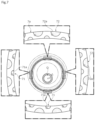
- FIG. 2 is a diagram illustrating a sliding surface of the side seal in the first embodiment of the present invention.
- FIG. 3 is a partially enlarged view illustrating high-pressure and low-pressure grooves in the sliding surface in the first embodiment of the present invention.
- FIG. 4 is a diagram illustrating relative sliding between the sliding surface of the side seal and a sliding surface of a thrust plate in the first embodiment of the present invention. It should be noted that FIG. 4 A illustrates the start position of the relative sliding and FIGS. 4 B to 4 D illustrate the positional relationships between the relatively sliding surfaces of the side seal and the thrust plate at an eccentric rotary shaft rotation of 90, 180, and 270 degrees, respectively.
- FIG. 5 is a diagram illustrating the distribution of the pressure generated in a plurality of grooves as a result of the relative movement of the groove entailed by the eccentric rotary shaft rotation in the sliding surface of the side seal illustrated in FIG. 4 A .
- FIG. 6 is a diagram illustrating the distribution of the pressure generated in the plurality of grooves as a result of the relative movement of the groove entailed by the eccentric rotary shaft rotation in the sliding surface of the side seal illustrated in FIG. 4 B .
- FIG. 7 is a diagram illustrating the distribution of the pressure generated in the plurality of grooves as a result of the relative movement of the groove entailed by the eccentric rotary shaft rotation in the sliding surface of the side seal illustrated in FIG. 4 C .
- FIG. 8 is a diagram illustrating the distribution of the pressure generated in the plurality of grooves as a result of the relative movement of the groove entailed by the eccentric rotary shaft rotation in the sliding surface of the side seal illustrated in FIG. 4 D .
- FIG. 9 is a diagram illustrating a sliding surface of a side seal as a sliding component according to a second embodiment of the present invention.
- FIG. 10 is a diagram illustrating a sliding surface of a side seal as a sliding component according to a third embodiment of the present invention.
- FIG. 11 is a diagram illustrating a sliding surface of a side seal as a sliding component according to a fourth embodiment of the present invention.
- FIGS. 1 to 8 The sliding component according to a first embodiment of the present invention will be described with reference to FIGS. 1 to 8 .
- the groove formed in the sliding surface of the sliding component or the like is dotted for convenience of description.
- the sliding component according to the first embodiment of the present invention is applied to a rotating machine including an eccentric mechanism such as a scroll compressor C that suctions, compresses, and discharges a refrigerant as a fluid used in the air conditioning system of an automobile or the like.
- a rotating machine including an eccentric mechanism such as a scroll compressor C that suctions, compresses, and discharges a refrigerant as a fluid used in the air conditioning system of an automobile or the like.
- the refrigerant in the present embodiment is a gas mixed with a mist-like lubricating oil.
- the scroll compressor C mainly includes a housing 1 , a rotary shaft 2 , an inner casing 3 , a scroll compression mechanism 4 , a side seal 7 as a sliding component, a thrust plate 8 , and a drive motor M.
- the housing 1 includes a cylindrical casing 11 and a cover 12 blocking one opening of the casing 11 .
- a low-pressure chamber 20 Formed in the casing 11 are a low-pressure chamber 20 , a high-pressure chamber 30 , and a back pressure chamber 50 .
- a low-pressure refrigerant is supplied from a refrigerant circuit (not illustrated) to the low-pressure chamber 20 through a suction port 10 .
- a high-pressure refrigerant compressed by the scroll compression mechanism 4 is discharged to the high-pressure chamber 30 .
- a part of the refrigerant compressed by the scroll compression mechanism 4 is supplied, together with lubricating oil, to the back pressure chamber 50 .
- the back pressure chamber 50 is formed in the cylindrical inner casing 3 accommodated in the casing 11 .
- a discharge communication passage 13 is formed in the cover 12 .
- the discharge communication passage 13 allows the refrigerant circuit (not illustrated) and the high-pressure chamber 30 to communicate with each other.
- a part of a back pressure communication passage 14 for communication between the high-pressure chamber 30 and the back pressure chamber 50 is formed in the cover 12 by branching off from the discharge communication passage 13 .
- the discharge communication passage 13 is provided with an oil separator 6 for lubricating oil separation from a refrigerant.
- the inner casing 3 is fixed with one end of the inner casing 3 abutting against an end plate 41 a of a fixed scroll 41 constituting the scroll compression mechanism 4 .
- a suction communication passage 15 penetrating it in the radial direction is formed in one end portion of the inner casing 3 .
- the low-pressure chamber 20 is formed from the outside of the inner casing 3 to the inside of the inner casing 3 via the suction communication passage 15 .
- the refrigerant supplied to the inside of the inner casing 3 through the suction communication passage 15 is suctioned into the scroll compression mechanism 4 .
- the scroll compression mechanism 4 mainly includes the fixed scroll 41 and a movable scroll 42 .
- the fixed scroll 41 is fixed to the cover 12 in a substantially sealed shape.
- the movable scroll 42 is accommodated in the inner casing 3 .
- the fixed scroll 41 is made of metal and includes a spiral lap 41 b .
- the spiral lap 41 b projects from the surface of the disk-shaped end plate 41 a , that is, one end surface of the end plate 41 a .
- a recessed portion 41 c recessed on the inner diameter side of the back surface of the end plate 41 a , that is, the other end surface of the end plate 41 a is formed in the fixed scroll 41 .
- the high-pressure chamber 30 is defined from the recessed portion 41 c and the end surface of the cover 12 .
- the movable scroll 42 is made of metal and includes a spiral lap 42 b .
- the spiral lap 42 b projects from the surface of a disk-shaped end plate 42 a , that is, one end surface of the end plate 42 a .
- a boss 42 c protruding from the middle of the back surface of the end plate 42 a , that is, the other end surface of the end plate 42 a is formed on the movable scroll 42 .
- An eccentric portion 2 a formed in one end portion of the rotary shaft 2 is fitted into the boss 42 c so as to be relatively rotatable.
- an eccentric mechanism causing the rotary shaft 2 to perform eccentric rotation is configured by the eccentric portion 2 a of the rotary shaft 2 and a counterweight portion 2 b protruding in the outer diameter direction from one end portion of the rotary shaft 2 in the present embodiment.
- the eccentric portion 2 a rotates eccentrically and the movable scroll 42 slides, in a posture-maintained state, relative to the fixed scroll 41 with the eccentric rotation.
- the movable scroll 42 rotates eccentrically with respect to the fixed scroll 41 and, with this rotation, the contact positions of the laps 41 b and 42 b sequentially move in the rotation direction and a compression chamber 40 formed between the laps 41 b and 42 b gradually shrinks while moving toward the middle.
- the side seal 7 as a sliding component in the present embodiment will be described.
- the side seal 7 is made of resin and has a rectangular cross section and an annular shape in an axial view.
- the side seal 7 is fixed to the back surface of the end plate 42 a of the movable scroll 42 (see FIG. 1 ). It should be noted that a sliding surface 7 a of the side seal 7 is illustrated in FIGS. 2 and 3 .
- the sliding surface 7 a abutting against a sliding surface 8 a of the thrust plate 8 is formed on one side surface of the side seal 7 .
- the sliding surface 7 a of the side seal 7 includes a land 79 , a plurality of high-pressure grooves 71 , and a plurality of low-pressure grooves 72 .
- the high-pressure groove 71 is recessed from a flat surface 79 a of the land 79 and is formed so as to be open to the back pressure chamber 50 (see FIG. 1 ), which is a space a high-pressure fluid is in, on the inner diameter side thereof.
- the low-pressure groove 72 is recessed from the flat surface 79 a of the land 79 and is formed so as to be open to the low-pressure chamber 20 (see FIG.
- the high-pressure groove 71 and the low-pressure groove 72 are arranged alternately inside and outside and substantially equally in the circumferential direction of the sliding surface 7 a.
- the high-pressure groove 71 is formed in a substantially semicircular shape having a center P 1 at the innermost diameter of the sliding surface 7 a .
- the low-pressure groove 72 is formed in a substantially semicircular shape having a center P 2 at the outermost diameter of the sliding surface 7 a .
- the high-pressure groove 71 and the low-pressure groove 72 are formed from a part of the direction parallel to the sliding surface 7 a , that is, a circle in an axial view.
- the high-pressure groove 71 is formed from a wall surface 71 a and a bottom surface 71 b .
- the wall surface 71 a extends substantially orthogonal to the surface 79 a of the land 79 , has a constant radius of curvature, and is continuously formed in a substantially semicircular arc shape.
- the bottom surface 71 b extends substantially orthogonal to the end portion of the wall surface 71 a and substantially parallel to the surface 79 a of the land 79 and is formed in a planar shape. It should be noted that the high-pressure grooves 71 have the same size but may be different in size.
- the low-pressure groove 72 is formed from a wall surface 72 a and a bottom surface 72 b .
- the wall surface 72 a extends substantially orthogonal to the surface 79 a of the land 79 , has a constant radius of curvature, and is continuously formed in a substantially semicircular arc shape.
- the bottom surface 72 b extends substantially orthogonal to the end portion of the wall surface 72 a and substantially parallel to the surface 79 a of the land 79 and is formed in a planar shape. It should be noted that the low-pressure grooves 72 have the same size but may be different in size.
- bottom surface 71 b of the high-pressure groove 71 and the bottom surface 72 b of the low-pressure groove 72 are not limited to those formed in a planar shape extending substantially parallel to the sliding surface 7 a and may be formed as, for example, inclined surfaces or curved surfaces.
- the depth dimension of the high-pressure groove 71 which is the dimension from the surface 79 a of the land 79 to the bottom surface 71 b of the high-pressure groove 71
- the depth dimension of the low-pressure groove 72 which is the dimension from the surface 79 a of the land 79 to the bottom surface 72 b of the low-pressure groove 72
- the depth dimensions of the high-pressure groove 71 and the low-pressure groove 72 are not limited to those substantially the same.
- the low-pressure groove 72 is formed larger than the high-pressure groove 71 in area in the direction parallel to the sliding surface 7 a (that is, axial-view area). Specifically, a radius R 2 of the low-pressure groove 72 , which is the dimension from the center P 2 to the wall surface 72 a in the low-pressure groove 72 , is longer than a radius R 1 of the high-pressure groove 71 , which is the dimension from the center P 1 to the wall surface 71 a in the high-pressure groove 71 (i.e., R 1 ⁇ R 2 ).
- a circumferential dimension L 2 of the low-pressure groove 72 is longer than a circumferential dimension L 4 of the land part between the adjacent low-pressure grooves 72 (L 2 >L 4 ).
- the plurality of low-pressure grooves 72 are densely formed over the circumferential direction of the sliding surface 7 a and the opening area of the low-pressure groove 72 into which the fluid flows from the space on the outer diameter side of the sliding surface 7 a is large.
- the wall surface 72 a of the low-pressure groove 72 extends to a position on the inner diameter side as compared with the middle of the sliding surface 7 a in the radial direction.
- the low-pressure groove 72 has a large fluid holding capacity.
- the circumferential dimension L 2 of the low-pressure groove 72 is shorter than a circumferential dimension L 3 of the land part between the adjacent high-pressure grooves 71 (i.e., L 2 ⁇ L 3 ) and a circumferential dimension L 1 of the high-pressure groove 71 is shorter than the circumferential dimension L 4 of the land part between the adjacent low-pressure grooves 72 (i.e., L 1 ⁇ L 4 ).
- the thrust plate 8 is made of metal and has an annular shape.
- a seal ring 43 is fixed to one end surface of the thrust plate 8 .
- the seal ring 43 abuts against the inside surface of the inner casing 3 .
- the thrust plate 8 functions as a thrust bearing that receives an axial load of the movable scroll 42 via the side seal 7 .
- the side seal 7 and the seal ring 43 partition the low-pressure chamber 20 formed on the outer diameter side of the movable scroll 42 and the back pressure chamber 50 formed on the back surface side of the movable scroll 42 in the inner casing 3 .
- the back pressure chamber 50 is a closed section formed between the inner casing 3 and the rotary shaft 2 .
- a seal ring 44 is fixed to the inner periphery of a through hole 3 a provided in the middle of the other end of the inner casing 3 and is in sliding contact in a sealed shape with the rotary shaft 2 inserted through the through hole 3 a .
- the back pressure communication passage 14 allowing the high-pressure chamber 30 and the back pressure chamber 50 to communicate with each other is formed over the cover 12 , the fixed scroll 41 , and the inner casing 3 .
- the back pressure communication passage 14 is provided with an orifice (not illustrated) and, after depressurization adjustment by means of the orifice, the refrigerant in the high-pressure chamber 30 is supplied to the back pressure chamber 50 together with the lubricating oil separated by the oil separator 6 . As a result, the pressure in the back pressure chamber 50 is adjusted to be higher than the pressure in the low-pressure chamber 20 .
- a pressure release hole 16 is formed in the inner casing 3 , penetrates the inner casing 3 in the radial direction, and allows the low-pressure chamber 20 and the back pressure chamber 50 to communicate with each other.
- a pressure adjustment valve 45 is provided in the pressure release hole 16 . The pressure adjustment valve 45 is opened by the pressure of the back pressure chamber 50 exceeding a set value.
- the boss 42 c of the movable scroll 42 is inserted through a through hole 8 b in the middle of the thrust plate 8 .
- the through hole 8 b is formed to have a diameter size at which it is possible to allow eccentric rotation by the eccentric portion 2 a of the rotary shaft 2 fitted into the boss 42 c .
- the sliding surface 7 a of the side seal 7 is capable of sliding relative to the sliding surface 8 a of the thrust plate 8 with eccentric rotation by the eccentric rotation of the rotary shaft 2 (see FIG. 4 ).
- FIGS. 4 A to 4 D in FIG. 4 illustrate the rotational trajectory of the boss 42 c that is viewed from the fixed scroll 41 side (see FIG. 1 ).
- Respectively illustrated in FIGS. 4 B to 4 D are the boss 42 c rotated by 90 degrees, 180 degrees, and 270 degrees with FIG. 4 A indicated by a black arrow serving as the clockwise reference.
- the sliding region between the sliding surface 7 a of the side seal 7 and the sliding surface 8 a of the thrust plate 8 is schematically illustrated by dots.
- the counterweight portion 2 b constituting the eccentric mechanism and so on are not illustrated and only the eccentric portion 2 a fitted into the boss 42 c is illustrated for convenience of description.
- the side seal 7 is a sliding component having the sliding surface 7 a sliding relative to the sliding surface 8 a of the thrust plate 8 with the eccentric rotation.
- FIGS. 5 to 8 dynamic pressure generation during the sliding of the side seal 7 relative to the thrust plate 8 will be described with reference to FIGS. 5 to 8 .
- a fluid containing, for example, a refrigerant and lubricating oil flows into the high-pressure groove 71 and the low-pressure groove 72 even when the rotation is stopped.
- the side seal 7 that is viewed from the drive motor M side is illustrated in each of FIGS. 5 to 8 and the circle marks on the wall surface 71 a of the high-pressure groove 71 and the wall surface 72 a of the low-pressure groove 72 indicate the points where the pressure is highest in the high-pressure groove 71 and the low-pressure groove 72 , respectively.
- the fluid in the high-pressure groove 71 and the low-pressure groove 72 receives a shear force in a direction substantially opposite to the direction in which the side seal 7 moves and moves in that direction.
- the sliding surfaces 7 a and 8 a are slightly separated from each other and a fluid film is formed by the fluid flowing in between the sliding surfaces 7 a and 8 a .
- the lubricity between the sliding surfaces 7 a and 8 a is improved, and thus the frictional resistance between the sliding surfaces 7 a and 8 a decreases.
- dynamic pressure is generated in each high-pressure groove 71 formed in a range of approximately 180 degrees on the inner diameter side of the sliding surface 7 a from the right side of the page to the upper side of the page and dynamic pressure is generated in each low-pressure groove 72 formed in a range of approximately 180 degrees on the outer diameter side of the sliding surface 7 a from the left side of the page to the lower side of the page.
- each high-pressure groove 71 the fluid in the high-pressure groove 71 moves toward the region on the upper left side of the wall surface 71 a and dynamic pressure is generated.
- the fluid in the low-pressure groove 72 moves toward the region on the upper left side of the wall surface 72 a and dynamic pressure is generated.
- dynamic pressure is generated in each high-pressure groove 71 formed in a range of approximately 180 degrees on the inner diameter side of the sliding surface 7 a from the upper side of the page to the left side of the page and dynamic pressure is generated in each low-pressure groove 72 formed in a range of approximately 180 degrees on the outer diameter side of the sliding surface 7 a from the lower side of the page to the right side of the page.
- each high-pressure groove 71 the fluid in the high-pressure groove 71 moves toward the region on the lower left side of the wall surface 71 a and dynamic pressure is generated.
- the fluid in the low-pressure groove 72 moves toward the region on the lower left side of the wall surface 72 a and dynamic pressure is generated.
- dynamic pressure is generated in each high-pressure groove 71 formed in a range of approximately 180 degrees on the inner diameter side of the sliding surface 7 a from the left side of the page to the lower side of the page and dynamic pressure is generated in each low-pressure groove 72 formed in a range of approximately 180 degrees on the outer diameter side of the sliding surface 7 a from the right side of the page to the upper side of the page.
- each high-pressure groove 71 the fluid in the high-pressure groove 71 moves toward the region on the lower right side of the wall surface 71 a and dynamic pressure is generated.
- the fluid in the low-pressure groove 72 moves toward the region on the lower right side of the wall surface 72 a and dynamic pressure is generated.
- dynamic pressure is generated in each high-pressure groove 71 formed in a range of approximately 180 degrees on the inner diameter side of the sliding surface 7 a from the lower side of the page to the right side of the page and dynamic pressure is generated in each low-pressure groove 72 formed in a range of approximately 180 degrees on the outer diameter side of the sliding surface 7 a from the upper side of the page to the left side of the page.
- the radial width of the side seal 7 where the high-pressure groove 71 and the low-pressure groove 72 are formed in the sliding surface 7 a is smaller than the radial width of the relatively sliding thrust plate 8 (see FIGS. 1 and 4 ). According to this, between the sliding surfaces 7 a and 8 a sliding relative to each other with the eccentric rotation, the entire sliding surface 7 a of the side seal 7 is always positioned in the sliding region between the sliding surface 7 a of the side seal 7 and the sliding surface 8 a of the thrust plate 8 (See FIG. 4 ). As a result, dynamic pressure can be reliably generated by the high-pressure groove 71 and the low-pressure groove 72 .
- the wall surfaces 71 a and 72 a are formed in a substantially semicircular arc shape in an axial view. Accordingly, in each high-pressure groove 71 and each low-pressure groove 72 , the points of the pressure generated on the wall surfaces 71 a and 72 a gradually move in a range of approximately 180 degrees along the wall surfaces 71 a and 72 a in accordance with the rotation angle of the boss 42 c (see FIGS. 5 to 8 ).
- the wall surfaces 71 a and 72 a having a substantially semicircular arc shape are continuous with the same radius of curvature, and thus the pressure generated in each high-pressure groove 71 and low-pressure groove 72 is substantially the same regardless of the eccentric rotation angle.
- the dynamic pressure generated in each high-pressure groove 71 and low-pressure groove 72 between the sliding surfaces 7 a and 8 a is unlikely to change sharply, and the generated dynamic pressure is stable.
- the low-pressure groove 72 is formed larger in axial-view area than the high-pressure groove 71 , and the pressure generated in the high-pressure groove 71 and the pressure generated in the low-pressure groove 72 are balanced so as to be substantially the same.
- the high-pressure groove 71 and the low-pressure groove 72 are arranged alternately inside and outside and substantially equally in the circumferential direction of the sliding surface 7 a . Accordingly, in accordance with the direction of relative movement of the high-pressure groove 71 and the low-pressure groove 72 entailed by eccentric rotation, dynamic pressure is generated in each high-pressure groove 71 formed in a range of approximately 180 degrees on the inner diameter side of the sliding surface 7 a and dynamic pressure is generated in each low-pressure groove 72 formed in a range of approximately 180 degrees half a lap off the range in the circumferential direction on the outer diameter side of the sliding surface 7 a (see FIGS. 5 to 8 ). In other words, between the sliding surfaces 7 a and 8 a , substantially the same dynamic pressure is generated over the circumferential direction by each high-pressure groove 71 and each low-pressure groove 72 .
- the lubricity between the sliding surfaces 7 a and 8 a can be improved by forming a fluid film by slightly separating the sliding surfaces 7 a and 8 a from each other, and thus the frictional resistance of the sliding surfaces 7 a and 8 a can be stably reduced.
- the low-pressure groove 72 is formed larger in axial-view area than the high-pressure groove 71 , and thus the dynamic pressure generated in the low-pressure groove 72 and the dynamic pressure generated in the high-pressure groove 71 can be balanced so as to be substantially the same in accordance with the direction of relative movement of the sliding surface 7 a entailed by eccentric rotation. Accordingly, the sliding surfaces 7 a and 8 a can be separated from each other substantially evenly in the circumferential direction, and the vibration, tilt, or the like of the side seal 7 attributable to dynamic pressure generation can be suppressed.
- the high-pressure groove 71 and the low-pressure groove 72 are disposed alternately inside and outside in the sliding surface 7 a , and thus dynamic pressure is generated in either the high-pressure groove 71 or the low-pressure groove 72 regardless of the direction of relative movement of the high-pressure groove 71 and the low-pressure groove 72 entailed by eccentric rotation. Accordingly, the dynamic pressure generated over the circumferential direction of the sliding surface 7 a is well-balanced. In addition, the regions of formation of the high-pressure groove 71 and the low-pressure groove 72 in the sliding surface 7 a are unlikely to interfere with each other, and thus the high-pressure groove 71 and the low-pressure groove 72 can be effectively formed with respect to the sliding surface 7 a.
- the low-pressure groove 72 is open to the low-pressure chamber 20 , the low-pressure chamber 20 is a space a low-pressure fluid is in, the low-pressure chamber 20 is a space on the outer diameter side of the sliding surface 7 a , and the low-pressure groove 72 is formed on the outer diameter side of the sliding surface 7 a . Accordingly, it is easy to ensure a large opening and a large axial-view area in the low-pressure groove 72 . 0
- the high-pressure groove 171 and the low-pressure groove 172 are formed in a substantially rectangular shape.
- the high-pressure groove 171 is formed from a wall surface 171 a , side wall surfaces 171 c and 171 d , and a bottom surface 171 b .
- the wall surface 171 a extends substantially orthogonal to a surface 179 a of a land 179 and extends linearly in the circumferential direction.
- the side wall surfaces 171 c and 171 d extend substantially orthogonal to the surface 179 a of the land 179 and extend linearly in the radial direction.
- the bottom surface 171 b extends substantially orthogonal to the end portions of the wall surface 171 a and the side wall surfaces 171 c and 171 d and substantially parallel to the surface 179 a of the land 179 and is formed in a planar shape.
- the low-pressure groove 172 is formed from a wall surface 172 a , side wall surfaces 172 c and 172 d , and a bottom surface 172 b .
- the wall surface 172 a extends substantially orthogonal to the surface 179 a of the land 179 and extends linearly in the circumferential direction.
- the side wall surfaces 172 c and 172 d extend substantially orthogonal to the surface 179 a of the land 179 and extend linearly in the radial direction.
- the bottom surface 172 b extends substantially orthogonal to the end portions of the wall surface 172 a and the side wall surfaces 172 c and 172 d and substantially parallel to the surface 179 a of the land 179 and is formed in a planar shape.
- a radial dimension L 14 of the low-pressure groove 172 is longer than a radial dimension L 13 of the high-pressure groove 171 (i.e., L 13 ⁇ L 14 ).
- the low-pressure groove 172 is formed larger in axial-view area than the high-pressure groove 171 .
- the low-pressure groove 172 extends to a position on the inner diameter side as compared with the middle of the sliding surface 107 a in the radial direction. As a result, the low-pressure groove 172 has a large fluid holding capacity.
- the fluid in the high-pressure groove 171 and the low-pressure groove 172 is concentrated in the corner portion formed by one of the side wall surfaces 171 c and 171 d and the wall surface 171 a constituting the high-pressure groove 171 and the corner portion formed by one of the side wall surfaces 172 c and 172 d and the wall surface 172 a constituting the low-pressure groove 172 . Accordingly, high dynamic pressure is generated in the high-pressure groove 171 and the low-pressure groove 172 .
- the high-pressure groove 271 and the low-pressure groove 272 are formed in a substantially rectangular shape.
- a circumferential dimension L 22 of the low-pressure groove 272 is longer than a circumferential dimension L 21 of the high-pressure groove 271 (i.e., L 21 ⁇ L 22 ).
- L 21 ⁇ L 22 the opening area of the low-pressure groove 272 into which a fluid flows from the space on the outer diameter side of a sliding surface 207 a is large.
- the low-pressure groove 272 is formed larger in axial-view area than the high-pressure groove 271 .
- the high-pressure groove 271 extends to a position on the outer diameter side as compared with the middle of the sliding surface 207 a in the radial direction
- the low-pressure groove 272 extends to a position on the inner diameter side as compared with the middle of the sliding surface 207 a in the radial direction.
- the high-pressure groove 271 and the low-pressure groove 272 are formed such that most thereof overlap in the circumferential direction.
- the fluid that has flowed between the sliding surfaces 207 a and 8 a out of the high-pressure groove 271 or the low-pressure groove 272 upstream in the circumferential direction as a result of dynamic pressure generation easily flows into the high-pressure groove 271 or the low-pressure groove 272 adjacent on the downstream side at that time. Not only is it easy for a fluid film to be formed by the fluid over the circumferential direction between the sliding surfaces 207 a and 8 a , but also the fluid on a land 279 is likely to be supplied into the high-pressure groove 271 or the low-pressure groove 272 .
- the high-pressure groove 371 and the low-pressure groove 372 are formed in a substantially isosceles trapezoidal shape, and the low-pressure groove 372 is formed larger in axial-view area than the high-pressure groove 371 .
- each of the high-pressure groove 371 and the low-pressure groove 372 is formed in a substantially isosceles trapezoidal shape having the largest circumferential dimension in the inner and outer openings.
- a large axial-view area is ensured at the land part between the high-pressure groove 371 and the low-pressure groove 372 adjacent to each other in the circumferential direction.
- the fluid that has flowed between a sliding surface 307 a and the sliding surface 8 a out of the high-pressure groove 371 or the low-pressure groove 372 as a result of dynamic pressure generation is likely to stay at the land part. Accordingly, it is possible to enhance sealability while ensuring the lubricity between the sliding surfaces 307 a and 8 a during sliding.
- a side seal as a sliding component is applied to a scroll compressor used in the air conditioning system of an automobile or the like
- the present invention is not limited thereto and the side seal as a sliding component may be applied to, for example, a scroll expansion compressor provided integrally with an expander and a compressor insofar as it is a rotating machine including an eccentric mechanism.
- each of the fluids in the spaces inside and outside the sliding surface of the sliding component may be any of a gas, a liquid, and a gas-liquid mixture.
- the high-pressure groove 71 is formed in a circular shape having the center P 1 at the innermost diameter of the sliding surface 7 a and the wall surface 71 a is formed in a substantially semicircular arc shape.
- the high-pressure groove may be any insofar as the wall surface is continuous in a circular arc shape.
- the high-pressure groove may be formed in a semi-elliptical shape and the wall surface may have a circular arc shape. It should be noted that the same applies to the low-pressure groove 72 .
- the low-pressure groove is formed larger in axial-view area than the high-pressure groove.
- the low-pressure groove may have the same axial-view area as the high-pressure groove or may be smaller in axial-view area than the high-pressure groove. It should be noted that in this case, balancing may be performed such that substantially the same dynamic pressure is generated in a range of 360 degrees over the circumferential direction between the sliding surfaces by forming more low-pressure grooves than high-pressure grooves.
- the sliding component of the present invention may be used in an environment in which the pressure inside the sliding surface and the pressure outside the sliding surface are substantially equal to each other without being limited to an environment in which there is a pressure difference between the inside and outside of the sliding surface.
- the sliding component of the present invention does not have to function as a seal and may be one capable of stably reducing the frictional resistance of a sliding surface.
- the side seal having the relatively sliding surface is made of resin and the thrust plate is made of metal in the embodiments, the material of the sliding component may be freely selected in accordance with the environment of use and so on.
- a groove may be formed in the sliding region of the sliding surface of the thrust plate (see FIG. 4 ), which is a sliding component having a sliding surface relatively sliding with eccentric rotation.
- grooves may be formed in both the sliding surface of the side seal and the sliding surface of the thrust plate.
- a groove may be formed in the sliding surface relatively sliding with eccentric rotation with only one of the side seal and the thrust plate provided.
- grooves may be formed in one or both of the sliding surface of the thrust plate as a sliding component and the back surface of the end plate of the movable scroll.
- a groove may be formed in the sliding surface of the side seal as a sliding component.
- the side seal also functions as a thrust bearing that abuts against the inner peripheral surface of the inner casing and receives the axial load of the movable scroll.
- a groove may be formed in the sliding surface formed on the back surface of the end plate of the movable scroll.
- the side seal has been described as a configuration that is annular in an axial view.
- the present invention is not limited thereto and the side seal may be formed in a disk shape in an axial view.
Landscapes
- Engineering & Computer Science (AREA)
- General Engineering & Computer Science (AREA)
- Mechanical Engineering (AREA)
- Physics & Mathematics (AREA)
- Fluid Mechanics (AREA)
- Chemical & Material Sciences (AREA)
- Oil, Petroleum & Natural Gas (AREA)
- Ocean & Marine Engineering (AREA)
- Rotary Pumps (AREA)
- Applications Or Details Of Rotary Compressors (AREA)
- Sliding-Contact Bearings (AREA)
- Mechanical Sealing (AREA)
Abstract
Description
-
- 1 Housing
- 2 Rotary shaft
- 2 a Eccentric portion
- 3 Inner casing
- 4 Scroll compression mechanism
- 6 Oil separator
- 7 Side seal (sliding component)
- 7 a Sliding surface
- 8 Thrust plate
- 8 a Sliding surface
- 10 Suction port
- 13 Discharge communication passage
- 14 Back pressure communication passage
- 15 Suction communication passage
- 20 Low-pressure chamber
- 30 High-pressure chamber
- 40 Compression chamber
- 41 Fixed scroll
- 42 Movable scroll
- 50 Back pressure chamber
- 71 High-pressure groove
- 72 Low-pressure groove
- 79 Land
- 107 Side seal (sliding component)
- 171 High-pressure groove
- 172 Low-pressure groove
- 207 Side seal (sliding component)
- 271 High-pressure groove
- 272 Low-pressure groove
- 307 Side seal (sliding component)
- 371 High-pressure groove
- 372 Low-pressure groove
- C Scroll compressor
- M Drive motor
- P1 Center of high-pressure groove
- P2 Center of low-pressure groove
Claims (16)
Applications Claiming Priority (3)
| Application Number | Priority Date | Filing Date | Title |
|---|---|---|---|
| JP2020-116357 | 2020-07-06 | ||
| JP2020116357 | 2020-07-06 | ||
| PCT/JP2021/024941 WO2022009768A1 (en) | 2020-07-06 | 2021-07-01 | Sliding component |
Publications (2)
| Publication Number | Publication Date |
|---|---|
| US20230258181A1 US20230258181A1 (en) | 2023-08-17 |
| US12135030B2 true US12135030B2 (en) | 2024-11-05 |
Family
ID=79552518
Family Applications (1)
| Application Number | Title | Priority Date | Filing Date |
|---|---|---|---|
| US18/012,856 Active US12135030B2 (en) | 2020-07-06 | 2021-07-01 | Sliding component |
Country Status (6)
| Country | Link |
|---|---|
| US (1) | US12135030B2 (en) |
| EP (1) | EP4177485A4 (en) |
| JP (1) | JP7475801B2 (en) |
| KR (1) | KR102868751B1 (en) |
| CN (1) | CN115917171A (en) |
| WO (1) | WO2022009768A1 (en) |
Families Citing this family (4)
| Publication number | Priority date | Publication date | Assignee | Title |
|---|---|---|---|---|
| EP4027028B1 (en) | 2019-09-02 | 2025-07-09 | Eagle Industry Co., Ltd. | Sliding component |
| JPWO2024106362A1 (en) * | 2022-11-17 | 2024-05-23 | ||
| CN121057892A (en) * | 2023-04-14 | 2025-12-02 | 伊格尔工业股份有限公司 | sliding parts |
| CN120367797A (en) * | 2024-01-23 | 2025-07-25 | 罗伯特·博世有限公司 | Scroll compressor having a rotor with a rotor shaft having a rotor shaft with a |
Citations (203)
| Publication number | Priority date | Publication date | Assignee | Title |
|---|---|---|---|---|
| US1876515A (en) | 1932-09-06 | Shaft packing | ||
| US2244450A (en) | 1938-04-28 | 1941-06-03 | Bbc Brown Boveri & Cie | Packing gland |
| US3380040A (en) | 1964-04-01 | 1968-04-23 | Hughes Aircraft Co | Hydrodynamic bearing support for a magnetic drum |
| US3383116A (en) | 1964-09-30 | 1968-05-14 | J C Carter Company | Face seal |
| US3527465A (en) | 1966-10-28 | 1970-09-08 | Etablis Pompes Guinard Sa | Rotary packing for use in rotary machines and more particularly in pumps |
| US3675935A (en) | 1970-07-13 | 1972-07-11 | Nasa | Spiral groove seal |
| US3695789A (en) * | 1970-04-13 | 1972-10-03 | Case Co J I | Balancing mechanism for fluid translating device |
| US3704019A (en) | 1970-06-19 | 1972-11-28 | Gen Electric | Spiral groove face seals |
| US3782737A (en) | 1970-07-13 | 1974-01-01 | Nasa | Spiral groove seal |
| JPS5134974A (en) | 1974-09-19 | 1976-03-25 | Kinugawa Rubber Ind | Dainamitsukushiiru no seiho |
| FR2342440A1 (en) | 1976-02-27 | 1977-09-23 | Ca Atomic Energy Ltd | Face seal for rotating shaft - has collar with chain of blind holes connected by grooves to increase resistance to flow |
| US4056478A (en) | 1973-10-04 | 1977-11-01 | Sargent Industries, Inc. | Bearing material employing frangible microcapsules containing lubricant |
| JPS52143571A (en) | 1976-05-21 | 1977-11-30 | Hoesch Werke Ag | Device for moving and exchaging rolls in roll working machine |
| US4071253A (en) | 1976-03-11 | 1978-01-31 | Gutehoffnungshutte Sterkrade A. G. | Gas-sealed shaft packing |
| GB1509482A (en) | 1975-02-01 | 1978-05-04 | Skf Ind Trading & Dev | Self-pressure-generating plain thrust bearing |
| JPS5693599U (en) | 1979-12-21 | 1981-07-25 | ||
| JPS57163770A (en) | 1981-04-01 | 1982-10-08 | Eagle Ind Co Ltd | Mechanical seal |
| DE3223703A1 (en) | 1982-06-25 | 1984-01-05 | M.A.N. Maschinenfabrik Augsburg-Nürnberg AG, 4200 Oberhausen | FLUID-LOCKED SHAFT SEAL WITH FLUID SUPPLY AND EXHAUST HOLES |
| JPS5960145U (en) | 1982-10-15 | 1984-04-19 | 株式会社太洋商会 | Rolled continuous bag |
| JPS59195253A (en) | 1983-04-20 | 1984-11-06 | Canon Inc | Electrophotographic apparatus |
| JPS59195254A (en) | 1983-04-20 | 1984-11-06 | Fujitsu Ltd | Printing device |
| JPS618402A (en) | 1984-06-20 | 1986-01-16 | Daikin Ind Ltd | scroll compressor |
| JPS63134883A (en) | 1986-11-27 | 1988-06-07 | Mitsubishi Electric Corp | scroll compressor |
| JPS63190975A (en) | 1986-10-28 | 1988-08-08 | パシフィック、ヴィーツ、ゲゼルシャフト、ミット、ベシュレンクテル、ハフツング、ウント、コンパニー、コンマンジットゲゼルシャフト | Airtight sealing device for shaft |
| US4889348A (en) | 1987-06-10 | 1989-12-26 | John Crane-Houdaille, Inc. | Spiral groove seal system for high vapor-pressure liquids |
| JPH0216381A (en) | 1988-07-01 | 1990-01-19 | Daikin Ind Ltd | Scroll type fluid device |
| EP0369295A1 (en) | 1988-11-18 | 1990-05-23 | Feodor Burgmann Dichtungswerke GmbH & Co. | Sliding annular seal |
| JPH02136863A (en) | 1988-11-18 | 1990-05-25 | Toshiba Corp | Developer for image forming device |
| JPH02236067A (en) | 1989-03-03 | 1990-09-18 | Nippon Pillar Packing Co Ltd | Non-contact end face type mechanical seal |
| US5071141A (en) | 1990-07-17 | 1991-12-10 | John Crane Inc. | Spiral groove seal arrangement for high vapor-pressure liquids |
| JPH0450559A (en) | 1990-06-18 | 1992-02-19 | Nippon Pillar Packing Co Ltd | Dynamic pressure non-contact type mechanical seal |
| JPH04337165A (en) | 1991-05-09 | 1992-11-25 | Nippon Pillar Packing Co Ltd | Non-contact type mechanical seal device |
| JPH04362289A (en) | 1991-06-11 | 1992-12-15 | Matsushita Electric Ind Co Ltd | scroll compressor |
| EP0518681A2 (en) | 1991-06-13 | 1992-12-16 | International Business Machines Corporation | Tape guide post |
| US5174584A (en) | 1991-07-15 | 1992-12-29 | General Electric Company | Fluid bearing face seal for gas turbine engines |
| US5180173A (en) | 1990-07-09 | 1993-01-19 | Ebara Corporation | Spiral groove face seal |
| JPH0560247A (en) | 1991-08-26 | 1993-03-09 | Nippon Pillar Packing Co Ltd | Noncontact type mechanical seal |
| JPH0590049A (en) | 1991-09-25 | 1993-04-09 | Hokkaido Electric Power Co Inc:The | Power supply and demand instrument transformer |
| US5224714A (en) | 1990-07-18 | 1993-07-06 | Ebara Corporation | Noncontacting face seal |
| GB2263952A (en) | 1992-02-06 | 1993-08-11 | Eagle Ind Co Ltd | Mechanical face seal |
| JPH05296248A (en) | 1992-04-21 | 1993-11-09 | Sumitomo Electric Ind Ltd | Sliding member |
| EP0589514A1 (en) | 1992-09-21 | 1994-03-30 | Koninklijke Philips Electronics N.V. | Method of manufacturing a dynamic groove bearing, die suitable for use in such a method, and housing and bearing part manufactured by such a method; data storage unit provided with such a groove bearing; method of manufacturing a rotatable scanning unit, and magnetic tape device provided with such a scanning unit |
| JPH06105105A (en) | 1992-09-18 | 1994-04-15 | Brother Ind Ltd | Color electrophotographic image forming apparatus |
| JPH06117547A (en) | 1992-10-07 | 1994-04-26 | Nippon Pillar Packing Co Ltd | Mechanical seal |
| US5316455A (en) | 1989-10-25 | 1994-05-31 | Matsushita Refrigeration Company | Rotary compressor with stabilized rotor |
| JPH06174107A (en) | 1992-12-11 | 1994-06-24 | Nippon Pillar Packing Co Ltd | Non-contact type shaft seal device |
| EP0637706A1 (en) | 1993-08-03 | 1995-02-08 | John Crane, Inc. | Improved non-contacting mechanical face seal |
| JPH0743038A (en) | 1993-07-30 | 1995-02-10 | Mitsubishi Heavy Ind Ltd | Absorption refrigerator |
| US5556111A (en) | 1993-09-01 | 1996-09-17 | Durametallic Corporation | Face seal with angled grooves and shallow annular groove |
| US5558341A (en) | 1995-01-11 | 1996-09-24 | Stein Seal Company | Seal for sealing an incompressible fluid between a relatively stationary seal and a movable member |
| JPH0989119A (en) | 1995-09-29 | 1997-03-31 | Nippon Pillar Packing Co Ltd | Shaft sealing device for liquid apparatus |
| JPH09228968A (en) | 1996-02-21 | 1997-09-02 | Hitachi Ltd | Scroll compressor |
| JPH09292034A (en) | 1996-04-25 | 1997-11-11 | Mitsubishi Heavy Ind Ltd | Mechanical seal |
| US5769604A (en) | 1995-05-04 | 1998-06-23 | Eg&G Sealol, Inc. | Face seal device having high angular compliance |
| JPH10281299A (en) | 1997-04-11 | 1998-10-23 | Mitsubishi Heavy Ind Ltd | Mechanical seal device |
| JPH10292867A (en) | 1997-04-16 | 1998-11-04 | Mitsubishi Heavy Ind Ltd | Gas seal device |
| US5834094A (en) | 1996-09-30 | 1998-11-10 | Surface Technologies Ltd. | Bearing having micropores and design method thereof |
| JPH10339286A (en) | 1997-06-05 | 1998-12-22 | Zexel Corp | Horizontal type scroll compressor |
| JPH11132163A (en) | 1997-10-23 | 1999-05-18 | Zexel:Kk | Transverse installation type scroll compressor |
| US5947481A (en) | 1996-08-02 | 1999-09-07 | Flowserve Management Company | Wavy face ring |
| JPH11287329A (en) | 1998-04-03 | 1999-10-19 | Eagle Ind Co Ltd | Sliding material |
| JPH11303858A (en) | 1998-04-17 | 1999-11-02 | Matsushita Electric Ind Co Ltd | Dynamic pressure porous bearing |
| JP3066367U (en) | 1999-08-05 | 2000-02-18 | 第一精工株式会社 | Recreational fishing containers and accessories |
| CN1245552A (en) | 1997-11-21 | 2000-02-23 | 日本皮拉工业株式会社 | Static pressure non-contact air seal |
| US6135458A (en) | 1997-11-21 | 2000-10-24 | Nippon Pillar Packing Co., Ltd. | Static pressure non-contact gas seal |
| US6152452A (en) | 1997-10-17 | 2000-11-28 | Wang; Yuming | Face seal with spiral grooves |
| JP2001012458A (en) | 1999-06-25 | 2001-01-16 | Matsushita Electric Ind Co Ltd | Dynamic pressure bearing and spindle motor having the same |
| US6213473B1 (en) | 1999-03-06 | 2001-04-10 | Utex Industries, Inc. | Double gas seal with coplanar pad faces |
| CN2460801Y (en) | 2001-01-18 | 2001-11-21 | 王玉明 | Sealing device for spiral flute end capable of bidirectional rotation |
| US20020014743A1 (en) | 2000-07-12 | 2002-02-07 | Xiaoqing Zheng | Rotary face seal assembly |
| DE10048256A1 (en) | 2000-09-29 | 2002-04-25 | Federal Mogul Wiesbaden Gmbh | Welding process to make camshaft bearing uses angled presentation to compensate for subsequent cooling |
| US6446976B1 (en) | 2000-09-06 | 2002-09-10 | Flowserve Management Company | Hydrodynamic face seal with grooved sealing dam for zero-leakage |
| US20020158416A1 (en) | 2001-04-26 | 2002-10-31 | John Crane Inc. | Non-contacting gas compressor seal |
| CN1401924A (en) | 2002-09-20 | 2003-03-12 | 徐万福 | Helical flute and face mechanial seal composed of angular microflute group |
| JP2003343730A (en) | 2002-05-23 | 2003-12-03 | Eagle Ind Co Ltd | Plate brush seal |
| US6692006B2 (en) | 2001-10-15 | 2004-02-17 | Stein Seal Company | High-pressure film-riding seals for rotating shafts |
| US20040080112A1 (en) | 2002-10-23 | 2004-04-29 | Eagle Industry Co., Ltd. | Sliding element |
| CN1529063A (en) | 2003-10-15 | 2004-09-15 | 哈尔滨工业大学 | Dynamic pressure ball bearing with inclined air collection groove and processing method of the air collection groove |
| JP2004360903A (en) | 2003-06-02 | 2004-12-24 | Minebea Co Ltd | Shaft sealing device and motor with shaft sealing device |
| CN1607710A (en) | 2003-10-14 | 2005-04-20 | 阿斯莫株式会社 | Motor rotation axis, thrust bearing structure of motor rotation axis |
| JP2005155894A (en) | 2003-10-31 | 2005-06-16 | Toyota Central Res & Dev Lab Inc | Fluid bearing |
| US20050135957A1 (en) | 2003-12-20 | 2005-06-23 | Lg Electronics Inc. | Oil supply device of scroll compressor |
| JP2005180652A (en) | 2003-12-22 | 2005-07-07 | Eagle Ind Co Ltd | Sliding parts |
| JP2005315391A (en) | 2004-04-30 | 2005-11-10 | Nippon Pillar Packing Co Ltd | Non-contact mechanical seal |
| US20050263963A1 (en) | 2004-05-28 | 2005-12-01 | Wei-Tang Lai | Mechanical seal ring assembly with hydrodynamic pumping mechanism |
| JP2006009614A (en) | 2004-06-23 | 2006-01-12 | Matsushita Electric Ind Co Ltd | Scroll compressor |
| JP2006077899A (en) | 2004-09-10 | 2006-03-23 | Nippon Pillar Packing Co Ltd | Non-contact sealing device |
| JP2006090524A (en) | 2004-09-27 | 2006-04-06 | Nissei Co Ltd | Dynamic pressure fluid bearing |
| WO2006051702A1 (en) | 2004-11-09 | 2006-05-18 | Eagle Industry Co., Ltd. | Mechanical seal device |
| JP2006183702A (en) | 2004-12-27 | 2006-07-13 | Hitachi Industrial Equipment Systems Co Ltd | Thrust bearing |
| JP2006316677A (en) | 2005-05-11 | 2006-11-24 | Denso Corp | Scroll compressor |
| JP2007162045A (en) | 2005-12-12 | 2007-06-28 | Japan Science & Technology Agency | Sliding material and manufacturing method thereof |
| US20070228664A1 (en) | 2006-03-31 | 2007-10-04 | Krishnamurthy Anand | Mechanical seals and methods of making |
| US20070267820A1 (en) | 2006-05-16 | 2007-11-22 | Skf Usa Inc. | Mechanical end face seal with ultrahard face material |
| US20070275267A1 (en) | 2006-05-26 | 2007-11-29 | Sulzer Metco Venture, Llc. | Mechanical seals and method of manufacture |
| US20080050260A1 (en) | 2006-08-25 | 2008-02-28 | Denso Corporation | Scroll compressor |
| JP2008051030A (en) | 2006-08-25 | 2008-03-06 | Denso Corp | Scroll compressor |
| JP2008051018A (en) | 2006-08-25 | 2008-03-06 | Denso Corp | Scroll compressor |
| US20080100001A1 (en) | 2006-10-25 | 2008-05-01 | Rexnord Industries, Llc | Hydrodynamic seal with circumferentially varying lift force |
| US20090200749A1 (en) | 2006-07-25 | 2009-08-13 | Eagle Industry Co., Ltd. | Mechanical seal device |
| EP2138225A2 (en) | 2008-06-27 | 2009-12-30 | Xerox Corporation | Method for treating microcapsules for use in imaging member |
| CN101644333A (en) | 2009-08-20 | 2010-02-10 | 浙江工业大学 | Gas end surface sealing structure with three-dimensional feather-like textured bottom shaped grooves |
| DE102008038396A1 (en) | 2008-08-19 | 2010-02-25 | Surcoatec International Ag | Sliding ring for a mechanical seal |
| CN201496542U (en) | 2009-08-06 | 2010-06-02 | 浙江工业大学 | Three-dimensional fish scale-constructed underside-type trough fluid dynamic-pressure type liquid mechanical sealing structure |
| US7758051B2 (en) | 2004-04-30 | 2010-07-20 | Aes Engineering Ltd | Gas seal assembly |
| CN101793324A (en) | 2009-08-06 | 2010-08-04 | 浙江工业大学 | Hydrodynamic mechanical seal structure for three-dimensional fish scale-like texture bottom surface type groove |
| CN101793169A (en) | 2009-01-06 | 2010-08-04 | 通用电气公司 | System and method for providing compliant rotating seals |
| CN101861485A (en) | 2007-11-20 | 2010-10-13 | 伊格尔工业股份有限公司 | Mechanical seal and tandem seal |
| JP2011074931A (en) | 2009-09-29 | 2011-04-14 | Ihi Corp | Sealing device for combustible gas compressor |
| US7931277B2 (en) | 2009-08-27 | 2011-04-26 | Stein Seal Company | Hydrodynamic circumferential seal system for large translations |
| US20110194966A1 (en) | 2008-12-02 | 2011-08-11 | Mitsubishi Heavy Industries, Ltd. | Scroll compressor |
| US20110215531A1 (en) | 2010-03-04 | 2011-09-08 | Eagle Industry Co., Ltd. | Sliding component |
| US20110215535A1 (en) | 2006-06-21 | 2011-09-08 | Stein Seal Company | Low and Reverse Pressure Application Hydrodynamic Pressurizing Seals |
| WO2011115073A1 (en) | 2010-03-15 | 2011-09-22 | イーグル工業株式会社 | Sliding member |
| US20110305871A1 (en) | 2009-02-10 | 2011-12-15 | Nok Corporation | Sliding Member and Process for Producing the Same |
| JP2012002295A (en) | 2010-06-17 | 2012-01-05 | Canon Machinery Inc | Plane sliding mechanism |
| US20120018957A1 (en) | 2010-02-26 | 2012-01-26 | Nok Corporation | Seal ring |
| JP2012062534A (en) | 2010-09-16 | 2012-03-29 | Jtekt Corp | Sliding member |
| WO2012046749A1 (en) | 2010-10-06 | 2012-04-12 | イーグル工業株式会社 | Sliding part |
| JP2012082794A (en) | 2010-10-14 | 2012-04-26 | Sanden Corp | Scroll fluid machine |
| JP2012122135A (en) | 2010-11-18 | 2012-06-28 | Furukawa Electric Co Ltd:The | Plating assistant, plating liquid, and plating material |
| WO2013035503A1 (en) | 2011-09-10 | 2013-03-14 | イーグル工業株式会社 | Sliding component |
| WO2013053411A1 (en) | 2011-10-14 | 2013-04-18 | Eagleburgmann Germany Gmbh & Co. Kg | Slide ring of a slide ring seal arrangement, having properties which lengthen the service life, and method for the production thereof |
| US20130168928A1 (en) | 2010-08-09 | 2013-07-04 | Eagleburgmann Germany Gmbh & Co. Kg | Sliding ring with improved run-in properties |
| CN203098871U (en) | 2013-01-30 | 2013-07-31 | 浙江工业大学 | Mushroom-like groove bidirectional rotating fluid moving compression mechanical sealing structure |
| JP2013167216A (en) | 2012-02-16 | 2013-08-29 | Mitsubishi Heavy Ind Ltd | Scroll type compressor |
| JP2013213545A (en) | 2012-04-02 | 2013-10-17 | Oiles Corp | Hydrostatic gas bearing and linear guide device using the hydrostatic gas bearing |
| US20130323105A1 (en) | 2010-12-22 | 2013-12-05 | Emerson Climate Technologies, Inc. | Thrust plate for a horizontal scroll compressor and a horizontal scroll compressor having the same |
| CN103557334A (en) | 2013-11-14 | 2014-02-05 | 江苏大学 | Multiple-end face combined type mechanical seal for realizing zero leakage and non-contact |
| CN103557229A (en) | 2013-10-22 | 2014-02-05 | 申科滑动轴承股份有限公司 | Design method of water lubrication step tile dynamic pressure thrust bearing |
| WO2014061544A1 (en) | 2012-10-18 | 2014-04-24 | イーグル工業株式会社 | Slide part |
| CN203641506U (en) | 2013-08-20 | 2014-06-11 | 浙江工业大学 | Tilted gradually-changed porous end surface non-contact mechanical seal structure |
| US20140159314A1 (en) | 2011-09-03 | 2014-06-12 | Eagle Industry Co.Ltd | Sliding parts |
| EP2754931A1 (en) | 2011-09-10 | 2014-07-16 | Eagle Industry Co., Ltd. | Sliding component |
| WO2014148317A1 (en) | 2013-03-17 | 2014-09-25 | イーグル工業株式会社 | Sliding part |
| WO2014148316A1 (en) | 2013-03-17 | 2014-09-25 | イーグル工業株式会社 | Sliding component |
| WO2014174725A1 (en) | 2013-04-24 | 2014-10-30 | イーグル工業株式会社 | Sliding part |
| CN104169622A (en) | 2012-05-21 | 2014-11-26 | 伊格尔工业股份有限公司 | Sliding component |
| CN104321568A (en) | 2012-09-11 | 2015-01-28 | 伊格尔工业股份有限公司 | sliding parts |
| JP2015063647A (en) | 2013-09-26 | 2015-04-09 | ポリプラスチックス株式会社 | Sliding member |
| JP2015068330A (en) | 2013-10-01 | 2015-04-13 | 三菱重工業株式会社 | Sliding member |
| US20150123350A1 (en) | 2012-08-04 | 2015-05-07 | Eagle Industry Co., Ltd. | Sliding component |
| CN104685273A (en) | 2013-03-14 | 2015-06-03 | 日本伊格尔博格曼有限公司 | Mechanical seal device |
| US20150184752A1 (en) * | 2012-12-25 | 2015-07-02 | Eagle Industry Co., Ltd. | Sliding component |
| WO2015111707A1 (en) | 2014-01-24 | 2015-07-30 | Nok株式会社 | Seal ring |
| JP2015183631A (en) | 2014-03-25 | 2015-10-22 | Ntn株式会社 | internal gear pump |
| US20150345642A1 (en) | 2014-05-29 | 2015-12-03 | Caterpillar Inc. | Thin film coating on mechanical face seals |
| WO2016035860A1 (en) | 2014-09-04 | 2016-03-10 | イーグル工業株式会社 | Mechanical seal |
| US20160097457A1 (en) | 2013-05-28 | 2016-04-07 | Nanjing Forestry University | Self-pumping hydrodynamic mechanical seal |
| JP2016061208A (en) | 2014-09-17 | 2016-04-25 | 三菱重工オートモーティブサーマルシステムズ株式会社 | Scroll compressor |
| JP2016080090A (en) | 2014-10-17 | 2016-05-16 | イーグル工業株式会社 | mechanical seal |
| CN205244387U (en) | 2015-12-10 | 2016-05-18 | 中国石油大学(华东) | Two -way rotatory petal -shaped terminal surface mechanical seal structure |
| CN106029294A (en) | 2014-02-24 | 2016-10-12 | 伊格尔工业股份有限公司 | Sliding member and method of processing the sliding member |
| WO2016167262A1 (en) | 2015-04-15 | 2016-10-20 | イーグル工業株式会社 | Sliding parts |
| US9494239B2 (en) | 2011-09-03 | 2016-11-15 | Eagle Industry Co., Ltd. | Sliding parts |
| WO2016186019A1 (en) | 2015-05-19 | 2016-11-24 | イーグル工業株式会社 | Sliding component |
| WO2016186015A1 (en) | 2015-05-20 | 2016-11-24 | イーグル工業株式会社 | Sliding component |
| WO2016186020A1 (en) | 2015-05-21 | 2016-11-24 | イーグル工業株式会社 | Sliding component |
| WO2016203878A1 (en) | 2015-06-15 | 2016-12-22 | イーグル工業株式会社 | Sliding part |
| WO2017002774A1 (en) | 2015-06-30 | 2017-01-05 | イーグル工業株式会社 | Seal device |
| CN205877198U (en) | 2016-06-20 | 2017-01-11 | 昆明理工大学 | Mechanical seal ring with oval groove |
| CN205877184U (en) | 2016-06-20 | 2017-01-11 | 昆明理工大学 | Mechanical seal ring with imitative chinese sweet gum lobate shaped groove |
| US9574666B2 (en) * | 2013-01-23 | 2017-02-21 | Flowserve Management Company | Mechanical face seal with a reverse trapezoidal face pattern |
| CN106439023A (en) | 2016-07-28 | 2017-02-22 | 浙江工业大学 | Cosine curve mechanical seal end surface structure |
| US20170089467A1 (en) * | 2015-09-25 | 2017-03-30 | Flowserve Management Company | Reverse pressure capable mechanical seal |
| WO2017061406A1 (en) | 2015-10-05 | 2017-04-13 | イーグル工業株式会社 | Sliding component |
| EP3196516A1 (en) | 2014-09-20 | 2017-07-26 | Eagle Industry Co., Ltd. | Sliding component |
| US20170241549A1 (en) | 2014-11-08 | 2017-08-24 | Eagle Industry Co., Ltd. | Slide component |
| US20170261107A1 (en) | 2016-03-10 | 2017-09-14 | General Electric Company | Seal ring assembly for a dynamoelectric machine |
| US9784372B2 (en) | 2009-05-25 | 2017-10-10 | Eagle Industry Co., Ltd. | Sealing device |
| US20170350407A1 (en) | 2014-12-22 | 2017-12-07 | Eagle Industry Co., Ltd. | Plain bearing and pump |
| CN107489770A (en) | 2017-09-29 | 2017-12-19 | 重庆三峡学院 | A kind of two-way mechanical sealing ring |
| US20180017163A1 (en) | 2015-02-14 | 2018-01-18 | Eagle Industry Co., Ltd. | Sliding component |
| WO2018025629A1 (en) | 2016-08-02 | 2018-02-08 | イーグル工業株式会社 | Sealing device |
| US20180112711A1 (en) | 2015-04-16 | 2018-04-26 | Eagle Industry Co., Ltd. | Slide component |
| US9958010B2 (en) | 2012-08-04 | 2018-05-01 | Eagle Industry Co., Ltd. | Sliding component |
| WO2018092742A1 (en) | 2016-11-16 | 2018-05-24 | イーグル工業株式会社 | Sliding component |
| US9982715B2 (en) | 2013-05-07 | 2018-05-29 | Mahle International Gmbh | Sliding engine component |
| CN108131386A (en) | 2017-12-22 | 2018-06-08 | 上海理工大学 | A kind of dynamic and static pressure cone revolute pair |
| WO2018105505A1 (en) | 2016-12-07 | 2018-06-14 | イーグル工業株式会社 | Sliding component |
| WO2018139231A1 (en) | 2017-01-30 | 2018-08-02 | イーグル工業株式会社 | Sliding component |
| EP3396186A1 (en) | 2015-12-25 | 2018-10-31 | Mitsubishi Materials Corporation | Sintered oil-retaining bearing and process for producing the same |
| CN109237042A (en) | 2018-11-14 | 2019-01-18 | 北京动力机械研究所 | Self-cleaning tooth form dynamic pressure type groove end surface mechanical sealing structure |
| US20190170257A1 (en) | 2016-09-01 | 2019-06-06 | Eagle Industry Co., Ltd. | Sliding component |
| US20190331162A1 (en) | 2016-11-14 | 2019-10-31 | Eagle Industry Co., Ltd. | Sliding component |
| EP3575621A1 (en) | 2017-01-30 | 2019-12-04 | Eagle Industry Co., Ltd. | Sliding component |
| CN110770456A (en) | 2017-07-07 | 2020-02-07 | 伊格尔工业股份有限公司 | Sliding component |
| CN110925426A (en) | 2019-12-26 | 2020-03-27 | 温州市天成密封件制造有限公司 | Upstream pumping mechanical sealing ring with elliptical groove |
| US20200141444A1 (en) | 2018-11-05 | 2020-05-07 | Azam Mihir Thatte | System and method for hybrid hydrodynamic-hydrostatic thrust bearings |
| WO2020129846A1 (en) | 2018-12-21 | 2020-06-25 | Tpr株式会社 | Thrust washer |
| US20200224768A1 (en) | 2017-10-03 | 2020-07-16 | Eagle Industry Co., Ltd. | Sliding component |
| US20200224722A1 (en) | 2017-07-14 | 2020-07-16 | Eagle Industry Co., Ltd. | Sliding parts |
| US20200240470A1 (en) | 2016-05-16 | 2020-07-30 | Roller Bearing Company Of America, Inc. | Bearing system with self-lubrication features, seals, grooves and slots for maintenance-free operation |
| CN111656065A (en) | 2018-02-01 | 2020-09-11 | 伊格尔工业股份有限公司 | sliding parts |
| US20200332901A1 (en) | 2018-01-12 | 2020-10-22 | Eagle Industry Co., Ltd. | Sliding component |
| US20210048062A1 (en) | 2017-07-13 | 2021-02-18 | Eagle Industry Co., Ltd. | Sliding member |
| US20210080009A1 (en) | 2018-05-17 | 2021-03-18 | Eagle Industry Co., Ltd. | Seal ring |
| US20210116030A1 (en) | 2018-05-17 | 2021-04-22 | Eagle Industry Co., Ltd. | Seal ring |
| US20210116032A1 (en) | 2018-05-17 | 2021-04-22 | Eagle Industry Co., Ltd. | Seal ring |
| WO2021125201A1 (en) | 2019-12-17 | 2021-06-24 | イーグル工業株式会社 | Sliding component |
| US11053975B2 (en) | 2017-05-19 | 2021-07-06 | Eagle Industry Co., Ltd | Sliding component |
| US20210364034A1 (en) | 2018-08-01 | 2021-11-25 | Eagle Industry Co., Ltd. | Slide component |
| US20230258182A1 (en) | 2020-07-06 | 2023-08-17 | Eagle Industry Co., Ltd. | Sliding component |
Family Cites Families (8)
| Publication number | Priority date | Publication date | Assignee | Title |
|---|---|---|---|---|
| JPH0647991B2 (en) * | 1986-05-15 | 1994-06-22 | 三菱電機株式会社 | Scroll compressor |
| JP2541227B2 (en) * | 1987-07-08 | 1996-10-09 | 三菱電機株式会社 | Scroll compressor |
| JPH0318671A (en) * | 1989-06-15 | 1991-01-28 | Daikin Ind Ltd | Axial piston device |
| JP2005325827A (en) * | 2004-04-13 | 2005-11-24 | Toshiba Kyaria Kk | Fluid machinery |
| JP5767959B2 (en) * | 2011-12-22 | 2015-08-26 | 大豊工業株式会社 | Sliding member |
| CN107850220A (en) * | 2015-07-10 | 2018-03-27 | 株式会社荏原制作所 | Non-contact annular seal and the rotating machinery for possessing the seal |
| CN109983201B (en) * | 2016-11-22 | 2021-01-12 | 伊格尔工业股份有限公司 | Sealing member |
| KR102541901B1 (en) * | 2018-12-21 | 2023-06-13 | 이구루코교 가부시기가이샤 | sliding parts |
-
2021
- 2021-07-01 KR KR1020237000902A patent/KR102868751B1/en active Active
- 2021-07-01 WO PCT/JP2021/024941 patent/WO2022009768A1/en not_active Ceased
- 2021-07-01 US US18/012,856 patent/US12135030B2/en active Active
- 2021-07-01 JP JP2022535277A patent/JP7475801B2/en active Active
- 2021-07-01 CN CN202180044576.6A patent/CN115917171A/en active Pending
- 2021-07-01 EP EP21836928.8A patent/EP4177485A4/en active Pending
Patent Citations (273)
| Publication number | Priority date | Publication date | Assignee | Title |
|---|---|---|---|---|
| US1876515A (en) | 1932-09-06 | Shaft packing | ||
| US2244450A (en) | 1938-04-28 | 1941-06-03 | Bbc Brown Boveri & Cie | Packing gland |
| US3380040A (en) | 1964-04-01 | 1968-04-23 | Hughes Aircraft Co | Hydrodynamic bearing support for a magnetic drum |
| US3383116A (en) | 1964-09-30 | 1968-05-14 | J C Carter Company | Face seal |
| US3527465A (en) | 1966-10-28 | 1970-09-08 | Etablis Pompes Guinard Sa | Rotary packing for use in rotary machines and more particularly in pumps |
| US3695789A (en) * | 1970-04-13 | 1972-10-03 | Case Co J I | Balancing mechanism for fluid translating device |
| US3704019A (en) | 1970-06-19 | 1972-11-28 | Gen Electric | Spiral groove face seals |
| US3782737A (en) | 1970-07-13 | 1974-01-01 | Nasa | Spiral groove seal |
| US3675935A (en) | 1970-07-13 | 1972-07-11 | Nasa | Spiral groove seal |
| US4056478A (en) | 1973-10-04 | 1977-11-01 | Sargent Industries, Inc. | Bearing material employing frangible microcapsules containing lubricant |
| JPS5134974A (en) | 1974-09-19 | 1976-03-25 | Kinugawa Rubber Ind | Dainamitsukushiiru no seiho |
| GB1509482A (en) | 1975-02-01 | 1978-05-04 | Skf Ind Trading & Dev | Self-pressure-generating plain thrust bearing |
| FR2342440A1 (en) | 1976-02-27 | 1977-09-23 | Ca Atomic Energy Ltd | Face seal for rotating shaft - has collar with chain of blind holes connected by grooves to increase resistance to flow |
| US4071253A (en) | 1976-03-11 | 1978-01-31 | Gutehoffnungshutte Sterkrade A. G. | Gas-sealed shaft packing |
| JPS52143571A (en) | 1976-05-21 | 1977-11-30 | Hoesch Werke Ag | Device for moving and exchaging rolls in roll working machine |
| JPS5693599U (en) | 1979-12-21 | 1981-07-25 | ||
| JPS57163770A (en) | 1981-04-01 | 1982-10-08 | Eagle Ind Co Ltd | Mechanical seal |
| US4523764A (en) | 1982-06-25 | 1985-06-18 | M.A.N. Maschinenfabrik Augsburg-Nurnberg Aktiengesellschaft | Fluid-sealed shaft seal with bores for supplying and discharging fluid |
| DE3223703A1 (en) | 1982-06-25 | 1984-01-05 | M.A.N. Maschinenfabrik Augsburg-Nürnberg AG, 4200 Oberhausen | FLUID-LOCKED SHAFT SEAL WITH FLUID SUPPLY AND EXHAUST HOLES |
| JPS5960145U (en) | 1982-10-15 | 1984-04-19 | 株式会社太洋商会 | Rolled continuous bag |
| JPS59195254A (en) | 1983-04-20 | 1984-11-06 | Fujitsu Ltd | Printing device |
| JPS59195253A (en) | 1983-04-20 | 1984-11-06 | Canon Inc | Electrophotographic apparatus |
| JPS618402A (en) | 1984-06-20 | 1986-01-16 | Daikin Ind Ltd | scroll compressor |
| US5092612A (en) * | 1986-10-28 | 1992-03-03 | Pacific Wietz Gmbh & Co. Kg | Contactless pressurizing-gas shaft seal |
| JPS63190975A (en) | 1986-10-28 | 1988-08-08 | パシフィック、ヴィーツ、ゲゼルシャフト、ミット、ベシュレンクテル、ハフツング、ウント、コンパニー、コンマンジットゲゼルシャフト | Airtight sealing device for shaft |
| JPS63134883A (en) | 1986-11-27 | 1988-06-07 | Mitsubishi Electric Corp | scroll compressor |
| US4889348A (en) | 1987-06-10 | 1989-12-26 | John Crane-Houdaille, Inc. | Spiral groove seal system for high vapor-pressure liquids |
| JPH0216381A (en) | 1988-07-01 | 1990-01-19 | Daikin Ind Ltd | Scroll type fluid device |
| EP0369295A1 (en) | 1988-11-18 | 1990-05-23 | Feodor Burgmann Dichtungswerke GmbH & Co. | Sliding annular seal |
| JPH02136863A (en) | 1988-11-18 | 1990-05-25 | Toshiba Corp | Developer for image forming device |
| JPH02236067A (en) | 1989-03-03 | 1990-09-18 | Nippon Pillar Packing Co Ltd | Non-contact end face type mechanical seal |
| US5316455A (en) | 1989-10-25 | 1994-05-31 | Matsushita Refrigeration Company | Rotary compressor with stabilized rotor |
| JPH0450559A (en) | 1990-06-18 | 1992-02-19 | Nippon Pillar Packing Co Ltd | Dynamic pressure non-contact type mechanical seal |
| JPH0617941A (en) | 1990-07-09 | 1994-01-25 | Ebara Corp | Non-contact end face seal |
| US5180173A (en) | 1990-07-09 | 1993-01-19 | Ebara Corporation | Spiral groove face seal |
| US5071141A (en) | 1990-07-17 | 1991-12-10 | John Crane Inc. | Spiral groove seal arrangement for high vapor-pressure liquids |
| JPH06323442A (en) | 1990-07-17 | 1994-11-25 | John Crane Inc | Spiral groove seal-arrangement for high vapor pressure liquid |
| US5224714A (en) | 1990-07-18 | 1993-07-06 | Ebara Corporation | Noncontacting face seal |
| JPH04337165A (en) | 1991-05-09 | 1992-11-25 | Nippon Pillar Packing Co Ltd | Non-contact type mechanical seal device |
| JPH04362289A (en) | 1991-06-11 | 1992-12-15 | Matsushita Electric Ind Co Ltd | scroll compressor |
| EP0518681A2 (en) | 1991-06-13 | 1992-12-16 | International Business Machines Corporation | Tape guide post |
| US5174584A (en) | 1991-07-15 | 1992-12-29 | General Electric Company | Fluid bearing face seal for gas turbine engines |
| JPH0560247A (en) | 1991-08-26 | 1993-03-09 | Nippon Pillar Packing Co Ltd | Noncontact type mechanical seal |
| JPH0590049A (en) | 1991-09-25 | 1993-04-09 | Hokkaido Electric Power Co Inc:The | Power supply and demand instrument transformer |
| GB2263952A (en) | 1992-02-06 | 1993-08-11 | Eagle Ind Co Ltd | Mechanical face seal |
| US5447316A (en) | 1992-02-06 | 1995-09-05 | Eagle Industry Co., Ltd. | Gas seal |
| JPH05296248A (en) | 1992-04-21 | 1993-11-09 | Sumitomo Electric Ind Ltd | Sliding member |
| JPH06105105A (en) | 1992-09-18 | 1994-04-15 | Brother Ind Ltd | Color electrophotographic image forming apparatus |
| JPH06200927A (en) | 1992-09-21 | 1994-07-19 | Philips Electronics Nv | Manufacture of dynamic groove bearing and mold used for such method |
| EP0589514A1 (en) | 1992-09-21 | 1994-03-30 | Koninklijke Philips Electronics N.V. | Method of manufacturing a dynamic groove bearing, die suitable for use in such a method, and housing and bearing part manufactured by such a method; data storage unit provided with such a groove bearing; method of manufacturing a rotatable scanning unit, and magnetic tape device provided with such a scanning unit |
| JPH06117547A (en) | 1992-10-07 | 1994-04-26 | Nippon Pillar Packing Co Ltd | Mechanical seal |
| JPH06174107A (en) | 1992-12-11 | 1994-06-24 | Nippon Pillar Packing Co Ltd | Non-contact type shaft seal device |
| JPH0743038A (en) | 1993-07-30 | 1995-02-10 | Mitsubishi Heavy Ind Ltd | Absorption refrigerator |
| EP0637706A1 (en) | 1993-08-03 | 1995-02-08 | John Crane, Inc. | Improved non-contacting mechanical face seal |
| US5556111A (en) | 1993-09-01 | 1996-09-17 | Durametallic Corporation | Face seal with angled grooves and shallow annular groove |
| US5558341A (en) | 1995-01-11 | 1996-09-24 | Stein Seal Company | Seal for sealing an incompressible fluid between a relatively stationary seal and a movable member |
| US5769604A (en) | 1995-05-04 | 1998-06-23 | Eg&G Sealol, Inc. | Face seal device having high angular compliance |
| JPH0989119A (en) | 1995-09-29 | 1997-03-31 | Nippon Pillar Packing Co Ltd | Shaft sealing device for liquid apparatus |
| JPH09228968A (en) | 1996-02-21 | 1997-09-02 | Hitachi Ltd | Scroll compressor |
| JPH09292034A (en) | 1996-04-25 | 1997-11-11 | Mitsubishi Heavy Ind Ltd | Mechanical seal |
| US5947481A (en) | 1996-08-02 | 1999-09-07 | Flowserve Management Company | Wavy face ring |
| US5952080A (en) | 1996-09-30 | 1999-09-14 | Surface Technologies Ltd. | Bearing having micropores, and design method thereof |
| US5834094A (en) | 1996-09-30 | 1998-11-10 | Surface Technologies Ltd. | Bearing having micropores and design method thereof |
| US6002100A (en) | 1996-09-30 | 1999-12-14 | Surface Technologies Ltd. | Bearing having micropores and design method thereof |
| US6046430A (en) | 1996-09-30 | 2000-04-04 | Surface Technologies Ltd. | Bearing having micropores, and design method therefor |
| JPH10281299A (en) | 1997-04-11 | 1998-10-23 | Mitsubishi Heavy Ind Ltd | Mechanical seal device |
| JPH10292867A (en) | 1997-04-16 | 1998-11-04 | Mitsubishi Heavy Ind Ltd | Gas seal device |
| JPH10339286A (en) | 1997-06-05 | 1998-12-22 | Zexel Corp | Horizontal type scroll compressor |
| US6152452A (en) | 1997-10-17 | 2000-11-28 | Wang; Yuming | Face seal with spiral grooves |
| JPH11132163A (en) | 1997-10-23 | 1999-05-18 | Zexel:Kk | Transverse installation type scroll compressor |
| CN1245552A (en) | 1997-11-21 | 2000-02-23 | 日本皮拉工业株式会社 | Static pressure non-contact air seal |
| US6135458A (en) | 1997-11-21 | 2000-10-24 | Nippon Pillar Packing Co., Ltd. | Static pressure non-contact gas seal |
| JPH11287329A (en) | 1998-04-03 | 1999-10-19 | Eagle Ind Co Ltd | Sliding material |
| JPH11303858A (en) | 1998-04-17 | 1999-11-02 | Matsushita Electric Ind Co Ltd | Dynamic pressure porous bearing |
| US6213473B1 (en) | 1999-03-06 | 2001-04-10 | Utex Industries, Inc. | Double gas seal with coplanar pad faces |
| JP2001012458A (en) | 1999-06-25 | 2001-01-16 | Matsushita Electric Ind Co Ltd | Dynamic pressure bearing and spindle motor having the same |
| JP3066367U (en) | 1999-08-05 | 2000-02-18 | 第一精工株式会社 | Recreational fishing containers and accessories |
| US20020014743A1 (en) | 2000-07-12 | 2002-02-07 | Xiaoqing Zheng | Rotary face seal assembly |
| US6446976B1 (en) | 2000-09-06 | 2002-09-10 | Flowserve Management Company | Hydrodynamic face seal with grooved sealing dam for zero-leakage |
| DE10048256A1 (en) | 2000-09-29 | 2002-04-25 | Federal Mogul Wiesbaden Gmbh | Welding process to make camshaft bearing uses angled presentation to compensate for subsequent cooling |
| US20020093141A1 (en) | 2001-01-18 | 2002-07-18 | Yuming Wang | Bi-direction rotatable face seal with spiral grooves |
| CN2460801Y (en) | 2001-01-18 | 2001-11-21 | 王玉明 | Sealing device for spiral flute end capable of bidirectional rotation |
| US6726213B2 (en) | 2001-01-18 | 2004-04-27 | Yuming Wang | Bi-direction rotatable face seal with spiral grooves |
| US20020158416A1 (en) | 2001-04-26 | 2002-10-31 | John Crane Inc. | Non-contacting gas compressor seal |
| US6692006B2 (en) | 2001-10-15 | 2004-02-17 | Stein Seal Company | High-pressure film-riding seals for rotating shafts |
| JP2003343730A (en) | 2002-05-23 | 2003-12-03 | Eagle Ind Co Ltd | Plate brush seal |
| CN1401924A (en) | 2002-09-20 | 2003-03-12 | 徐万福 | Helical flute and face mechanial seal composed of angular microflute group |
| US20040080112A1 (en) | 2002-10-23 | 2004-04-29 | Eagle Industry Co., Ltd. | Sliding element |
| JP2004360903A (en) | 2003-06-02 | 2004-12-24 | Minebea Co Ltd | Shaft sealing device and motor with shaft sealing device |
| CN1607710A (en) | 2003-10-14 | 2005-04-20 | 阿斯莫株式会社 | Motor rotation axis, thrust bearing structure of motor rotation axis |
| CN1529063A (en) | 2003-10-15 | 2004-09-15 | 哈尔滨工业大学 | Dynamic pressure ball bearing with inclined air collection groove and processing method of the air collection groove |
| JP2005155894A (en) | 2003-10-31 | 2005-06-16 | Toyota Central Res & Dev Lab Inc | Fluid bearing |
| US20050135957A1 (en) | 2003-12-20 | 2005-06-23 | Lg Electronics Inc. | Oil supply device of scroll compressor |
| JP2005180652A (en) | 2003-12-22 | 2005-07-07 | Eagle Ind Co Ltd | Sliding parts |
| US20050212217A1 (en) | 2003-12-22 | 2005-09-29 | Eagle Industry Co., Ltd. | Sliding element |
| US7258346B2 (en) | 2003-12-22 | 2007-08-21 | Eagle Industry Co., Ltd. | Sliding element |
| JP2005315391A (en) | 2004-04-30 | 2005-11-10 | Nippon Pillar Packing Co Ltd | Non-contact mechanical seal |
| US7758051B2 (en) | 2004-04-30 | 2010-07-20 | Aes Engineering Ltd | Gas seal assembly |
| JP2005337503A (en) | 2004-05-28 | 2005-12-08 | John Crane Inc | Mechanical seal ring assembly with hydrodynamic pump mechanism |
| US7377518B2 (en) | 2004-05-28 | 2008-05-27 | John Crane Inc. | Mechanical seal ring assembly with hydrodynamic pumping mechanism |
| US20050263963A1 (en) | 2004-05-28 | 2005-12-01 | Wei-Tang Lai | Mechanical seal ring assembly with hydrodynamic pumping mechanism |
| JP2006009614A (en) | 2004-06-23 | 2006-01-12 | Matsushita Electric Ind Co Ltd | Scroll compressor |
| JP2006077899A (en) | 2004-09-10 | 2006-03-23 | Nippon Pillar Packing Co Ltd | Non-contact sealing device |
| JP2006090524A (en) | 2004-09-27 | 2006-04-06 | Nissei Co Ltd | Dynamic pressure fluid bearing |
| WO2006051702A1 (en) | 2004-11-09 | 2006-05-18 | Eagle Industry Co., Ltd. | Mechanical seal device |
| US20070296156A1 (en) | 2004-11-09 | 2007-12-27 | Takashi Yanagisawa | Mechanical Seal Device |
| JP2006183702A (en) | 2004-12-27 | 2006-07-13 | Hitachi Industrial Equipment Systems Co Ltd | Thrust bearing |
| JP2006316677A (en) | 2005-05-11 | 2006-11-24 | Denso Corp | Scroll compressor |
| JP2007162045A (en) | 2005-12-12 | 2007-06-28 | Japan Science & Technology Agency | Sliding material and manufacturing method thereof |
| US20070228664A1 (en) | 2006-03-31 | 2007-10-04 | Krishnamurthy Anand | Mechanical seals and methods of making |
| US20070267820A1 (en) | 2006-05-16 | 2007-11-22 | Skf Usa Inc. | Mechanical end face seal with ultrahard face material |
| US20070275267A1 (en) | 2006-05-26 | 2007-11-29 | Sulzer Metco Venture, Llc. | Mechanical seals and method of manufacture |
| US8342534B2 (en) | 2006-06-21 | 2013-01-01 | Stein Seal Company | Low and reverse pressure application hydrodynamic pressurizing seals |
| US20110215535A1 (en) | 2006-06-21 | 2011-09-08 | Stein Seal Company | Low and Reverse Pressure Application Hydrodynamic Pressurizing Seals |
| US20090200749A1 (en) | 2006-07-25 | 2009-08-13 | Eagle Industry Co., Ltd. | Mechanical seal device |
| JP2008051018A (en) | 2006-08-25 | 2008-03-06 | Denso Corp | Scroll compressor |
| JP2008051030A (en) | 2006-08-25 | 2008-03-06 | Denso Corp | Scroll compressor |
| US20080050260A1 (en) | 2006-08-25 | 2008-02-28 | Denso Corporation | Scroll compressor |
| JP2008106940A (en) | 2006-10-25 | 2008-05-08 | Rexnord Industries Llc | Hydrodynamic seal with circumferentially varying lift |
| US20080100001A1 (en) | 2006-10-25 | 2008-05-01 | Rexnord Industries, Llc | Hydrodynamic seal with circumferentially varying lift force |
| US8585060B2 (en) | 2007-11-20 | 2013-11-19 | Eagle Industry Co., Ltd. | Tandem seal device |
| CN101861485A (en) | 2007-11-20 | 2010-10-13 | 伊格尔工业股份有限公司 | Mechanical seal and tandem seal |
| EP2138225A2 (en) | 2008-06-27 | 2009-12-30 | Xerox Corporation | Method for treating microcapsules for use in imaging member |
| DE102008038396A1 (en) | 2008-08-19 | 2010-02-25 | Surcoatec International Ag | Sliding ring for a mechanical seal |
| US20110194966A1 (en) | 2008-12-02 | 2011-08-11 | Mitsubishi Heavy Industries, Ltd. | Scroll compressor |
| CN101793169A (en) | 2009-01-06 | 2010-08-04 | 通用电气公司 | System and method for providing compliant rotating seals |
| US8100405B2 (en) | 2009-01-06 | 2012-01-24 | General Electric Company | System and method for providing compliant rotating seals |
| US20110305871A1 (en) | 2009-02-10 | 2011-12-15 | Nok Corporation | Sliding Member and Process for Producing the Same |
| US9784372B2 (en) | 2009-05-25 | 2017-10-10 | Eagle Industry Co., Ltd. | Sealing device |
| CN101793324A (en) | 2009-08-06 | 2010-08-04 | 浙江工业大学 | Hydrodynamic mechanical seal structure for three-dimensional fish scale-like texture bottom surface type groove |
| CN201496542U (en) | 2009-08-06 | 2010-06-02 | 浙江工业大学 | Three-dimensional fish scale-constructed underside-type trough fluid dynamic-pressure type liquid mechanical sealing structure |
| CN101644333A (en) | 2009-08-20 | 2010-02-10 | 浙江工业大学 | Gas end surface sealing structure with three-dimensional feather-like textured bottom shaped grooves |
| US7931277B2 (en) | 2009-08-27 | 2011-04-26 | Stein Seal Company | Hydrodynamic circumferential seal system for large translations |
| JP2011074931A (en) | 2009-09-29 | 2011-04-14 | Ihi Corp | Sealing device for combustible gas compressor |
| US20120018957A1 (en) | 2010-02-26 | 2012-01-26 | Nok Corporation | Seal ring |
| JP2011185292A (en) | 2010-03-04 | 2011-09-22 | Eagle Industry Co Ltd | Sliding component |
| US20110215531A1 (en) | 2010-03-04 | 2011-09-08 | Eagle Industry Co., Ltd. | Sliding component |
| US9169931B2 (en) | 2010-03-04 | 2015-10-27 | Eagle Industry Co., Ltd. | Sliding component |
| WO2011115073A1 (en) | 2010-03-15 | 2011-09-22 | イーグル工業株式会社 | Sliding member |
| US9228660B2 (en) | 2010-03-15 | 2016-01-05 | Eagle Industry Co., Ltd. | Sliding member |
| US20120217705A1 (en) | 2010-03-15 | 2012-08-30 | Eagle Industry Co., Ltd. | Sliding member |
| JP2012002295A (en) | 2010-06-17 | 2012-01-05 | Canon Machinery Inc | Plane sliding mechanism |
| US20130168928A1 (en) | 2010-08-09 | 2013-07-04 | Eagleburgmann Germany Gmbh & Co. Kg | Sliding ring with improved run-in properties |
| JP2012062534A (en) | 2010-09-16 | 2012-03-29 | Jtekt Corp | Sliding member |
| WO2012046749A1 (en) | 2010-10-06 | 2012-04-12 | イーグル工業株式会社 | Sliding part |
| US20130209011A1 (en) | 2010-10-06 | 2013-08-15 | Eagle Industry Co., Ltd. | Sliding component |
| JP5693599B2 (en) | 2010-10-06 | 2015-04-01 | イーグル工業株式会社 | Sliding parts |
| US20140294330A1 (en) | 2010-10-06 | 2014-10-02 | Eagle Industry Co., Ltd. | Sliding component |
| JP2012082794A (en) | 2010-10-14 | 2012-04-26 | Sanden Corp | Scroll fluid machine |
| JP2012122135A (en) | 2010-11-18 | 2012-06-28 | Furukawa Electric Co Ltd:The | Plating assistant, plating liquid, and plating material |
| US20130323105A1 (en) | 2010-12-22 | 2013-12-05 | Emerson Climate Technologies, Inc. | Thrust plate for a horizontal scroll compressor and a horizontal scroll compressor having the same |
| US9494239B2 (en) | 2011-09-03 | 2016-11-15 | Eagle Industry Co., Ltd. | Sliding parts |
| US20140159314A1 (en) | 2011-09-03 | 2014-06-12 | Eagle Industry Co.Ltd | Sliding parts |
| EP2754931A1 (en) | 2011-09-10 | 2014-07-16 | Eagle Industry Co., Ltd. | Sliding component |
| JP5960145B2 (en) | 2011-09-10 | 2016-08-02 | イーグル工業株式会社 | Sliding parts and manufacturing method thereof |
| US9151390B2 (en) | 2011-09-10 | 2015-10-06 | Eagle Industry Co., Ltd. | Sliding parts |
| WO2013035503A1 (en) | 2011-09-10 | 2013-03-14 | イーグル工業株式会社 | Sliding component |
| US20140197600A1 (en) | 2011-09-10 | 2014-07-17 | Eagle Industry Co., Ltd. | Sliding parts |
| US20140217676A1 (en) | 2011-09-10 | 2014-08-07 | Eagle Industry Co., Ltd. | Sliding parts |
| JP2014529052A (en) | 2011-10-14 | 2014-10-30 | イーグルブルクマン ジャーマニー ゲセルシャフト ミト ベシュレンクテル ハフツング ウント コンパニー コマンディトゲゼルシャフト | SEAL RING FOR MECHANICAL SEAL ASSEMBLY HAVING CHARACTERISTIC EXTENDING TIME |
| US20140319776A1 (en) | 2011-10-14 | 2014-10-30 | Jörg Theike | Seal ring of a mechanical seal assembly having properties extending the running time, and method for the production thereof |
| WO2013053411A1 (en) | 2011-10-14 | 2013-04-18 | Eagleburgmann Germany Gmbh & Co. Kg | Slide ring of a slide ring seal arrangement, having properties which lengthen the service life, and method for the production thereof |
| JP2013167216A (en) | 2012-02-16 | 2013-08-29 | Mitsubishi Heavy Ind Ltd | Scroll type compressor |
| JP2013213545A (en) | 2012-04-02 | 2013-10-17 | Oiles Corp | Hydrostatic gas bearing and linear guide device using the hydrostatic gas bearing |
| CN104169622A (en) | 2012-05-21 | 2014-11-26 | 伊格尔工业股份有限公司 | Sliding component |
| US9512923B2 (en) | 2012-05-21 | 2016-12-06 | Eagle Industry Co., Ltd. | Sliding component |
| US9772037B2 (en) | 2012-08-04 | 2017-09-26 | Eagle Industry Co., Ltd. | Sliding component |
| US20150123350A1 (en) | 2012-08-04 | 2015-05-07 | Eagle Industry Co., Ltd. | Sliding component |
| US9958010B2 (en) | 2012-08-04 | 2018-05-01 | Eagle Industry Co., Ltd. | Sliding component |
| CN104321568A (en) | 2012-09-11 | 2015-01-28 | 伊格尔工业股份有限公司 | sliding parts |
| US20150115540A1 (en) | 2012-09-11 | 2015-04-30 | Eagle Industry Co. Ltd | Sliding component |
| US20150167847A1 (en) | 2012-10-18 | 2015-06-18 | Eagle Industry Co., Ltd. | Sliding component |
| WO2014061544A1 (en) | 2012-10-18 | 2014-04-24 | イーグル工業株式会社 | Slide part |
| US20150184752A1 (en) * | 2012-12-25 | 2015-07-02 | Eagle Industry Co., Ltd. | Sliding component |
| US9574666B2 (en) * | 2013-01-23 | 2017-02-21 | Flowserve Management Company | Mechanical face seal with a reverse trapezoidal face pattern |
| CN203098871U (en) | 2013-01-30 | 2013-07-31 | 浙江工业大学 | Mushroom-like groove bidirectional rotating fluid moving compression mechanical sealing structure |
| US9574667B2 (en) | 2013-03-14 | 2017-02-21 | Eagle Burgmann Japan Co., Ltd. | Mechanical seal device |
| CN104685273A (en) | 2013-03-14 | 2015-06-03 | 日本伊格尔博格曼有限公司 | Mechanical seal device |
| WO2014148316A1 (en) | 2013-03-17 | 2014-09-25 | イーグル工業株式会社 | Sliding component |
| US9353867B2 (en) | 2013-03-17 | 2016-05-31 | Eagle Industry Co., Ltd. | Sliding parts |
| US20150377297A1 (en) | 2013-03-17 | 2015-12-31 | Eagle Industry Co., Ltd. | Sliding parts |
| WO2014148317A1 (en) | 2013-03-17 | 2014-09-25 | イーグル工業株式会社 | Sliding part |
| WO2014174725A1 (en) | 2013-04-24 | 2014-10-30 | イーグル工業株式会社 | Sliding part |
| US20160033045A1 (en) | 2013-04-24 | 2016-02-04 | Eagle Industry Co., Ltd. | Sliding component |
| US9982715B2 (en) | 2013-05-07 | 2018-05-29 | Mahle International Gmbh | Sliding engine component |
| US20160097457A1 (en) | 2013-05-28 | 2016-04-07 | Nanjing Forestry University | Self-pumping hydrodynamic mechanical seal |
| CN203641506U (en) | 2013-08-20 | 2014-06-11 | 浙江工业大学 | Tilted gradually-changed porous end surface non-contact mechanical seal structure |
| JP2015063647A (en) | 2013-09-26 | 2015-04-09 | ポリプラスチックス株式会社 | Sliding member |
| JP2015068330A (en) | 2013-10-01 | 2015-04-13 | 三菱重工業株式会社 | Sliding member |
| CN103557229A (en) | 2013-10-22 | 2014-02-05 | 申科滑动轴承股份有限公司 | Design method of water lubrication step tile dynamic pressure thrust bearing |
| CN103557334A (en) | 2013-11-14 | 2014-02-05 | 江苏大学 | Multiple-end face combined type mechanical seal for realizing zero leakage and non-contact |
| US10865883B2 (en) | 2014-01-24 | 2020-12-15 | Nok Corporation | Sealing ring |
| WO2015111707A1 (en) | 2014-01-24 | 2015-07-30 | Nok株式会社 | Seal ring |
| CN106029294A (en) | 2014-02-24 | 2016-10-12 | 伊格尔工业股份有限公司 | Sliding member and method of processing the sliding member |
| US9863473B2 (en) | 2014-02-24 | 2018-01-09 | Eagle Industry Co., Ltd. | Sliding parts and processing method of sliding parts |
| EP3112078A1 (en) | 2014-02-24 | 2017-01-04 | Eagle Industry Co., Ltd. | Sliding member and sliding member processing method |
| JP2015183631A (en) | 2014-03-25 | 2015-10-22 | Ntn株式会社 | internal gear pump |
| US20150345642A1 (en) | 2014-05-29 | 2015-12-03 | Caterpillar Inc. | Thin film coating on mechanical face seals |
| US10054230B2 (en) | 2014-09-04 | 2018-08-21 | Eagles Industry Co., Ltd. | Mechanical seal |
| WO2016035860A1 (en) | 2014-09-04 | 2016-03-10 | イーグル工業株式会社 | Mechanical seal |
| JP2016061208A (en) | 2014-09-17 | 2016-04-25 | 三菱重工オートモーティブサーマルシステムズ株式会社 | Scroll compressor |
| US20170146014A1 (en) | 2014-09-17 | 2017-05-25 | Mitsubishi Heavy Industries Automotive Thermal Systems Co., Ltd. | Scroll compressor |
| EP3196516A1 (en) | 2014-09-20 | 2017-07-26 | Eagle Industry Co., Ltd. | Sliding component |
| JP2016080090A (en) | 2014-10-17 | 2016-05-16 | イーグル工業株式会社 | mechanical seal |
| US10443737B2 (en) | 2014-11-08 | 2019-10-15 | Eagle Industry Co., Ltd. | Slide component |
| US20170241549A1 (en) | 2014-11-08 | 2017-08-24 | Eagle Industry Co., Ltd. | Slide component |
| EP3217049A1 (en) | 2014-11-08 | 2017-09-13 | Eagle Industry Co., Ltd. | Sliding parts |
| US20170350407A1 (en) | 2014-12-22 | 2017-12-07 | Eagle Industry Co., Ltd. | Plain bearing and pump |
| US10132411B2 (en) | 2015-02-14 | 2018-11-20 | Eagle Industry Co., Ltd. | Sliding component |
| US20180017163A1 (en) | 2015-02-14 | 2018-01-18 | Eagle Industry Co., Ltd. | Sliding component |
| WO2016167262A1 (en) | 2015-04-15 | 2016-10-20 | イーグル工業株式会社 | Sliding parts |
| US20180073394A1 (en) | 2015-04-15 | 2018-03-15 | Eagle Industry Co., Ltd. | Sliding component |
| US20180112711A1 (en) | 2015-04-16 | 2018-04-26 | Eagle Industry Co., Ltd. | Slide component |
| US20180128377A1 (en) | 2015-05-19 | 2018-05-10 | Eagle Industry Co., Ltd. | Slide component |
| WO2016186019A1 (en) | 2015-05-19 | 2016-11-24 | イーグル工業株式会社 | Sliding component |
| US20180135699A1 (en) | 2015-05-20 | 2018-05-17 | Eagle Industry Co., Ltd. | Sliding component |
| WO2016186015A1 (en) | 2015-05-20 | 2016-11-24 | イーグル工業株式会社 | Sliding component |
| WO2016186020A1 (en) | 2015-05-21 | 2016-11-24 | イーグル工業株式会社 | Sliding component |
| US20180128378A1 (en) | 2015-05-21 | 2018-05-10 | Eagle Industry Co., Ltd. | Sliding component |
| US10337620B2 (en) | 2015-05-21 | 2019-07-02 | Eagle Industry Co., Ltd. | Sliding component |
| WO2016203878A1 (en) | 2015-06-15 | 2016-12-22 | イーグル工業株式会社 | Sliding part |
| US20180172162A1 (en) | 2015-06-15 | 2018-06-21 | Eagle Industry Co., Ltd. | Slide component |
| US10495228B2 (en) | 2015-06-30 | 2019-12-03 | Eagle Industry Co., Ltd. | Sealing device |
| WO2017002774A1 (en) | 2015-06-30 | 2017-01-05 | イーグル工業株式会社 | Seal device |
| US20180195618A1 (en) | 2015-06-30 | 2018-07-12 | Eagle Industry Co., Ltd. | Sealing device |
| US20170089467A1 (en) * | 2015-09-25 | 2017-03-30 | Flowserve Management Company | Reverse pressure capable mechanical seal |
| WO2017061406A1 (en) | 2015-10-05 | 2017-04-13 | イーグル工業株式会社 | Sliding component |
| US20180299015A1 (en) | 2015-10-05 | 2018-10-18 | Eagle Industry Co., Ltd. | Sliding component |
| CN205244387U (en) | 2015-12-10 | 2016-05-18 | 中国石油大学(华东) | Two -way rotatory petal -shaped terminal surface mechanical seal structure |
| EP3396186A1 (en) | 2015-12-25 | 2018-10-31 | Mitsubishi Materials Corporation | Sintered oil-retaining bearing and process for producing the same |
| US20170261107A1 (en) | 2016-03-10 | 2017-09-14 | General Electric Company | Seal ring assembly for a dynamoelectric machine |
| US20200240470A1 (en) | 2016-05-16 | 2020-07-30 | Roller Bearing Company Of America, Inc. | Bearing system with self-lubrication features, seals, grooves and slots for maintenance-free operation |
| CN205877198U (en) | 2016-06-20 | 2017-01-11 | 昆明理工大学 | Mechanical seal ring with oval groove |
| CN205877184U (en) | 2016-06-20 | 2017-01-11 | 昆明理工大学 | Mechanical seal ring with imitative chinese sweet gum lobate shaped groove |
| CN106439023A (en) | 2016-07-28 | 2017-02-22 | 浙江工业大学 | Cosine curve mechanical seal end surface structure |
| US20190169988A1 (en) | 2016-08-02 | 2019-06-06 | Eagle Industry Co., Ltd. | Sealing device |
| WO2018025629A1 (en) | 2016-08-02 | 2018-02-08 | イーグル工業株式会社 | Sealing device |
| US20190170257A1 (en) | 2016-09-01 | 2019-06-06 | Eagle Industry Co., Ltd. | Sliding component |
| US20190331162A1 (en) | 2016-11-14 | 2019-10-31 | Eagle Industry Co., Ltd. | Sliding component |
| WO2018092742A1 (en) | 2016-11-16 | 2018-05-24 | イーグル工業株式会社 | Sliding component |
| US20190285115A1 (en) | 2016-11-16 | 2019-09-19 | Eagle Industry Co., Ltd. | Sliding component |
| US20190301522A1 (en) | 2016-12-07 | 2019-10-03 | Eagle Industry Co., Ltd. | Sliding component |
| WO2018105505A1 (en) | 2016-12-07 | 2018-06-14 | イーグル工業株式会社 | Sliding component |
| EP3575621A1 (en) | 2017-01-30 | 2019-12-04 | Eagle Industry Co., Ltd. | Sliding component |
| EP3575643A1 (en) | 2017-01-30 | 2019-12-04 | Eagle Industry Co., Ltd. | Sliding component |
| WO2018139231A1 (en) | 2017-01-30 | 2018-08-02 | イーグル工業株式会社 | Sliding component |
| US11053975B2 (en) | 2017-05-19 | 2021-07-06 | Eagle Industry Co., Ltd | Sliding component |
| EP3650722A1 (en) | 2017-07-07 | 2020-05-13 | Eagle Industry Co., Ltd. | Sliding member |
| CN110770456A (en) | 2017-07-07 | 2020-02-07 | 伊格尔工业股份有限公司 | Sliding component |
| US20210048106A1 (en) | 2017-07-07 | 2021-02-18 | Eagle Industry Co., Ltd. | Sliding member |
| US11248706B2 (en) | 2017-07-07 | 2022-02-15 | Eagle Industry Co., Ltd. | Sliding member |
| US20210048062A1 (en) | 2017-07-13 | 2021-02-18 | Eagle Industry Co., Ltd. | Sliding member |
| US20200224722A1 (en) | 2017-07-14 | 2020-07-16 | Eagle Industry Co., Ltd. | Sliding parts |
| CN107489770A (en) | 2017-09-29 | 2017-12-19 | 重庆三峡学院 | A kind of two-way mechanical sealing ring |
| US20200224768A1 (en) | 2017-10-03 | 2020-07-16 | Eagle Industry Co., Ltd. | Sliding component |
| CN108131386A (en) | 2017-12-22 | 2018-06-08 | 上海理工大学 | A kind of dynamic and static pressure cone revolute pair |
| US20200332901A1 (en) | 2018-01-12 | 2020-10-22 | Eagle Industry Co., Ltd. | Sliding component |
| US20210041026A1 (en) | 2018-02-01 | 2021-02-11 | Eagle Industry Co., Ltd. | Sliding components |
| US11320052B2 (en) | 2018-02-01 | 2022-05-03 | Eagle Industry Co., Ltd. | Sliding components |
| CN111656065A (en) | 2018-02-01 | 2020-09-11 | 伊格尔工业股份有限公司 | sliding parts |
| US20210080009A1 (en) | 2018-05-17 | 2021-03-18 | Eagle Industry Co., Ltd. | Seal ring |
| US20210116030A1 (en) | 2018-05-17 | 2021-04-22 | Eagle Industry Co., Ltd. | Seal ring |
| US20210116032A1 (en) | 2018-05-17 | 2021-04-22 | Eagle Industry Co., Ltd. | Seal ring |
| US20210364034A1 (en) | 2018-08-01 | 2021-11-25 | Eagle Industry Co., Ltd. | Slide component |
| US20200141444A1 (en) | 2018-11-05 | 2020-05-07 | Azam Mihir Thatte | System and method for hybrid hydrodynamic-hydrostatic thrust bearings |
| CN109237042A (en) | 2018-11-14 | 2019-01-18 | 北京动力机械研究所 | Self-cleaning tooth form dynamic pressure type groove end surface mechanical sealing structure |
| US20220056949A1 (en) | 2018-12-21 | 2022-02-24 | Tpr Co., Ltd. | Thrust washer |
| WO2020129846A1 (en) | 2018-12-21 | 2020-06-25 | Tpr株式会社 | Thrust washer |
| WO2021125201A1 (en) | 2019-12-17 | 2021-06-24 | イーグル工業株式会社 | Sliding component |
| US20230027772A1 (en) | 2019-12-17 | 2023-01-26 | Eagle Industry Co., Ltd. | Sliding component |
| CN110925426A (en) | 2019-12-26 | 2020-03-27 | 温州市天成密封件制造有限公司 | Upstream pumping mechanical sealing ring with elliptical groove |
| US20230258182A1 (en) | 2020-07-06 | 2023-08-17 | Eagle Industry Co., Ltd. | Sliding component |
| US11913454B2 (en) | 2020-07-06 | 2024-02-27 | Eagle Industry Co., Ltd. | Sliding component |
Non-Patent Citations (24)
| Title |
|---|
| Chinese Official Action issued in related Chinese Patent Application Serial No. 202180044553.5, dated Apr. 28, 2024, 13 pages with translation. |
| International Preliminary Report on Patentability issued in PCT/JP2021/024938, dated Jan. 10, 2023, 4 pages. |
| International Preliminary Report on Patentability issued in PCT/JP2021/024940, dated Jan. 10, 2023, 4 pages. |
| International Preliminary Report on Patentability issued in PCT/JP2021/024941, dated Jan. 10, 2023, 5 pages. |
| International Preliminary Report on Patentability issued in PCT/JP2021/024943, dated Jan. 10, 2023, 5 pages. |
| International Preliminary Report on Patentability issued in PCT/JP2021/024944, dated Jan. 10, 2023, 4 pages. |
| International Preliminary Report on Patentability issued in PCT/JP2021/024945, dated Jan. 10, 2023, 6 pages. |
| International Search Report and Written Opinion issued in PCT/JP2021/024938, dated Aug. 3, 2021, with English translation, 12 pages. |
| International Search Report and Written Opinion issued in PCT/JP2021/024940, dated Aug. 10, 2021, with English translation, 13 pages. |
| International Search Report and Written Opinion issued in PCT/JP2021/024941, dated Sep. 14, 2021, with English translation, 13 pages. |
| International Search Report and Written Opinion issued in PCT/JP2021/024943, dated Sep. 7, 2021, with English translation, 13 pages. |
| International Search Report and Written Opinion issued in PCT/JP2021/024944, dated Jul. 27, 2021, with English translation, 11 pages. |
| International Search Report and Written Opinion issued in PCT/JP2021/024945, dated Sep. 7, 2021, with English translation, 16 pages. |
| Japanese Official Action issued in related application serial No. 2022-535275, dated Feb. 13, 2024, 8 pages. |
| Notice of Allowance issued in related U.S. Appl. No. 18/013,515, dated Dec. 19, 2023, 10 pages. |
| Official Action issued in related U.S. Appl. No. 18/012,853, dated Sep. 8, 2023, 11 pages. |
| Official Action issued in related U.S. Appl. No. 18/012,857, dated Mar. 21, 2024, 13 pages. |
| Official Action issued in related U.S. Appl. No. 18/012,857, dated Oct. 5, 2023, 11 pages. |
| Official Action issued in related U.S. Appl. No. 18/013,513, dated Feb. 15, 2024, 9 pages. |
| U.S. Appl. No. 18/012,853, filed Dec. 23, 2022, Suzuki. |
| U.S. Appl. No. 18/012,857, filed Dec. 23, 2022, Suzuki. |
| U.S. Appl. No. 18/013,513, filed Dec. 28, 2022, Suzuki. |
| U.S. Appl. No. 18/013,515, filed Dec. 28, 2022, Suzuki. |
| U.S. Appl. No. 18/013,520, filed Dec. 28, 2022, Suzuki. |
Also Published As
| Publication number | Publication date |
|---|---|
| KR102868751B1 (en) | 2025-10-14 |
| JPWO2022009768A1 (en) | 2022-01-13 |
| WO2022009768A1 (en) | 2022-01-13 |
| US20230258181A1 (en) | 2023-08-17 |
| JP7475801B2 (en) | 2024-04-30 |
| CN115917171A (en) | 2023-04-04 |
| EP4177485A1 (en) | 2023-05-10 |
| EP4177485A4 (en) | 2024-07-24 |
| KR20230022987A (en) | 2023-02-16 |
Similar Documents
| Publication | Publication Date | Title |
|---|---|---|
| US12060909B2 (en) | Sliding component | |
| US11913454B2 (en) | Sliding component | |
| US11933303B2 (en) | Sliding component | |
| US12135030B2 (en) | Sliding component | |
| US12152676B2 (en) | Sliding component | |
| US12404935B2 (en) | Sliding component | |
| US12104598B2 (en) | Eccentric sliding assembly with a plurality of dynamic pressure generation mechanisms | |
| US11913449B2 (en) | Sliding component | |
| US12110923B2 (en) | Sliding component | |
| EP4621235A1 (en) | Thrust support mechanism | |
| WO2024214575A1 (en) | Sliding component |
Legal Events
| Date | Code | Title | Description |
|---|---|---|---|
| FEPP | Fee payment procedure |
Free format text: ENTITY STATUS SET TO UNDISCOUNTED (ORIGINAL EVENT CODE: BIG.); ENTITY STATUS OF PATENT OWNER: LARGE ENTITY |
|
| AS | Assignment |
Owner name: EAGLE INDUSTRY CO., LTD., JAPAN Free format text: ASSIGNMENT OF ASSIGNORS INTEREST;ASSIGNORS:SUZUKI, HIROSHI;TOKUNAGA, YUICHIRO;REEL/FRAME:062690/0758 Effective date: 20221010 |
|
| STPP | Information on status: patent application and granting procedure in general |
Free format text: DOCKETED NEW CASE - READY FOR EXAMINATION |
|
| STPP | Information on status: patent application and granting procedure in general |
Free format text: NON FINAL ACTION MAILED |
|
| STPP | Information on status: patent application and granting procedure in general |
Free format text: RESPONSE TO NON-FINAL OFFICE ACTION ENTERED AND FORWARDED TO EXAMINER |
|
| STPP | Information on status: patent application and granting procedure in general |
Free format text: FINAL REJECTION MAILED |
|
| STPP | Information on status: patent application and granting procedure in general |
Free format text: DOCKETED NEW CASE - READY FOR EXAMINATION |
|
| STPP | Information on status: patent application and granting procedure in general |
Free format text: NOTICE OF ALLOWANCE MAILED -- APPLICATION RECEIVED IN OFFICE OF PUBLICATIONS |
|
| STPP | Information on status: patent application and granting procedure in general |
Free format text: PUBLICATIONS -- ISSUE FEE PAYMENT RECEIVED |
|
| STPP | Information on status: patent application and granting procedure in general |
Free format text: PUBLICATIONS -- ISSUE FEE PAYMENT VERIFIED |
|
| STCF | Information on status: patent grant |
Free format text: PATENTED CASE |