US12090535B2 - Heating device for the inductive heating of a flat steel strip in a hot rolling mill - Google Patents
Heating device for the inductive heating of a flat steel strip in a hot rolling mill Download PDFInfo
- Publication number
- US12090535B2 US12090535B2 US17/599,088 US202017599088A US12090535B2 US 12090535 B2 US12090535 B2 US 12090535B2 US 202017599088 A US202017599088 A US 202017599088A US 12090535 B2 US12090535 B2 US 12090535B2
- Authority
- US
- United States
- Prior art keywords
- setpoint
- heating device
- transverse
- steel strip
- flat steel
- Prior art date
- Legal status (The legal status is an assumption and is not a legal conclusion. Google has not performed a legal analysis and makes no representation as to the accuracy of the status listed.)
- Active, expires
Links
- 238000010438 heat treatment Methods 0.000 title claims abstract description 193
- 229910000831 Steel Inorganic materials 0.000 title claims abstract description 140
- 239000010959 steel Substances 0.000 title claims abstract description 140
- 238000005098 hot rolling Methods 0.000 title claims abstract description 27
- 230000001939 inductive effect Effects 0.000 title claims abstract description 24
- 238000005096 rolling process Methods 0.000 claims abstract description 35
- 239000003990 capacitor Substances 0.000 claims abstract description 27
- 238000000034 method Methods 0.000 claims abstract description 12
- 238000009826 distribution Methods 0.000 description 8
- 238000004519 manufacturing process Methods 0.000 description 8
- 238000006243 chemical reaction Methods 0.000 description 4
- 230000008901 benefit Effects 0.000 description 3
- 230000008878 coupling Effects 0.000 description 3
- 238000010168 coupling process Methods 0.000 description 3
- 238000005859 coupling reaction Methods 0.000 description 3
- 230000004907 flux Effects 0.000 description 3
- 230000001965 increasing effect Effects 0.000 description 3
- 230000006698 induction Effects 0.000 description 3
- 230000003213 activating effect Effects 0.000 description 2
- 239000007795 chemical reaction product Substances 0.000 description 2
- 239000004020 conductor Substances 0.000 description 2
- 230000000694 effects Effects 0.000 description 2
- 238000004880 explosion Methods 0.000 description 2
- 239000000463 material Substances 0.000 description 2
- 238000013021 overheating Methods 0.000 description 2
- 239000000047 product Substances 0.000 description 2
- 230000004913 activation Effects 0.000 description 1
- 230000002411 adverse Effects 0.000 description 1
- 230000015572 biosynthetic process Effects 0.000 description 1
- 238000009529 body temperature measurement Methods 0.000 description 1
- 238000010276 construction Methods 0.000 description 1
- 230000009849 deactivation Effects 0.000 description 1
- 238000010586 diagram Methods 0.000 description 1
- 239000007789 gas Substances 0.000 description 1
- 238000000265 homogenisation Methods 0.000 description 1
- 230000008569 process Effects 0.000 description 1
- 230000011664 signaling Effects 0.000 description 1
- 238000011144 upstream manufacturing Methods 0.000 description 1
- XLYOFNOQVPJJNP-UHFFFAOYSA-N water Substances O XLYOFNOQVPJJNP-UHFFFAOYSA-N 0.000 description 1
Images


Classifications
-
- B—PERFORMING OPERATIONS; TRANSPORTING
- B21—MECHANICAL METAL-WORKING WITHOUT ESSENTIALLY REMOVING MATERIAL; PUNCHING METAL
- B21B—ROLLING OF METAL
- B21B37/00—Control devices or methods specially adapted for metal-rolling mills or the work produced thereby
- B21B37/74—Temperature control, e.g. by cooling or heating the rolls or the product
-
- B—PERFORMING OPERATIONS; TRANSPORTING
- B21—MECHANICAL METAL-WORKING WITHOUT ESSENTIALLY REMOVING MATERIAL; PUNCHING METAL
- B21B—ROLLING OF METAL
- B21B45/00—Devices for surface or other treatment of work, specially combined with or arranged in, or specially adapted for use in connection with, metal-rolling mills
- B21B45/004—Heating the product
-
- B—PERFORMING OPERATIONS; TRANSPORTING
- B21—MECHANICAL METAL-WORKING WITHOUT ESSENTIALLY REMOVING MATERIAL; PUNCHING METAL
- B21B—ROLLING OF METAL
- B21B1/00—Metal-rolling methods or mills for making semi-finished products of solid or profiled cross-section; Sequence of operations in milling trains; Layout of rolling-mill plant, e.g. grouping of stands; Succession of passes or of sectional pass alternations
- B21B1/02—Metal-rolling methods or mills for making semi-finished products of solid or profiled cross-section; Sequence of operations in milling trains; Layout of rolling-mill plant, e.g. grouping of stands; Succession of passes or of sectional pass alternations for rolling heavy work, e.g. ingots, slabs, blooms, or billets, in which the cross-sectional form is unimportant ; Rolling combined with forging or pressing
- B21B1/026—Rolling
-
- B—PERFORMING OPERATIONS; TRANSPORTING
- B21—MECHANICAL METAL-WORKING WITHOUT ESSENTIALLY REMOVING MATERIAL; PUNCHING METAL
- B21B—ROLLING OF METAL
- B21B1/00—Metal-rolling methods or mills for making semi-finished products of solid or profiled cross-section; Sequence of operations in milling trains; Layout of rolling-mill plant, e.g. grouping of stands; Succession of passes or of sectional pass alternations
- B21B1/02—Metal-rolling methods or mills for making semi-finished products of solid or profiled cross-section; Sequence of operations in milling trains; Layout of rolling-mill plant, e.g. grouping of stands; Succession of passes or of sectional pass alternations for rolling heavy work, e.g. ingots, slabs, blooms, or billets, in which the cross-sectional form is unimportant ; Rolling combined with forging or pressing
- B21B1/04—Metal-rolling methods or mills for making semi-finished products of solid or profiled cross-section; Sequence of operations in milling trains; Layout of rolling-mill plant, e.g. grouping of stands; Succession of passes or of sectional pass alternations for rolling heavy work, e.g. ingots, slabs, blooms, or billets, in which the cross-sectional form is unimportant ; Rolling combined with forging or pressing in a continuous process
-
- B—PERFORMING OPERATIONS; TRANSPORTING
- B21—MECHANICAL METAL-WORKING WITHOUT ESSENTIALLY REMOVING MATERIAL; PUNCHING METAL
- B21B—ROLLING OF METAL
- B21B37/00—Control devices or methods specially adapted for metal-rolling mills or the work produced thereby
- B21B37/28—Control of flatness or profile during rolling of strip, sheets or plates
- B21B37/44—Control of flatness or profile during rolling of strip, sheets or plates using heating, lubricating or water-spray cooling of the product
-
- C—CHEMISTRY; METALLURGY
- C21—METALLURGY OF IRON
- C21D—MODIFYING THE PHYSICAL STRUCTURE OF FERROUS METALS; GENERAL DEVICES FOR HEAT TREATMENT OF FERROUS OR NON-FERROUS METALS OR ALLOYS; MAKING METAL MALLEABLE, e.g. BY DECARBURISATION OR TEMPERING
- C21D1/00—General methods or devices for heat treatment, e.g. annealing, hardening, quenching or tempering
- C21D1/34—Methods of heating
- C21D1/42—Induction heating
-
- C—CHEMISTRY; METALLURGY
- C21—METALLURGY OF IRON
- C21D—MODIFYING THE PHYSICAL STRUCTURE OF FERROUS METALS; GENERAL DEVICES FOR HEAT TREATMENT OF FERROUS OR NON-FERROUS METALS OR ALLOYS; MAKING METAL MALLEABLE, e.g. BY DECARBURISATION OR TEMPERING
- C21D9/00—Heat treatment, e.g. annealing, hardening, quenching or tempering, adapted for particular articles; Furnaces therefor
- C21D9/52—Heat treatment, e.g. annealing, hardening, quenching or tempering, adapted for particular articles; Furnaces therefor for wires; for strips ; for rods of unlimited length
- C21D9/54—Furnaces for treating strips or wire
- C21D9/56—Continuous furnaces for strip or wire
- C21D9/60—Continuous furnaces for strip or wire with induction heating
-
- Y—GENERAL TAGGING OF NEW TECHNOLOGICAL DEVELOPMENTS; GENERAL TAGGING OF CROSS-SECTIONAL TECHNOLOGIES SPANNING OVER SEVERAL SECTIONS OF THE IPC; TECHNICAL SUBJECTS COVERED BY FORMER USPC CROSS-REFERENCE ART COLLECTIONS [XRACs] AND DIGESTS
- Y02—TECHNOLOGIES OR APPLICATIONS FOR MITIGATION OR ADAPTATION AGAINST CLIMATE CHANGE
- Y02P—CLIMATE CHANGE MITIGATION TECHNOLOGIES IN THE PRODUCTION OR PROCESSING OF GOODS
- Y02P10/00—Technologies related to metal processing
- Y02P10/25—Process efficiency
Definitions
- the flat steel strip is heated by a heating device, in particular an inductive heating device, which is arranged between the two rolling trains.
- the cause of this problem is that different thickness ranges of steel strips require different heating concepts, for example that the heating device generates in the steel strip a magnetic field with a specific working frequency transversely or longitudinally in relation to the transporting direction of the steel strip and the magnetic field is matched to a specific thickness range.
- the heating concept and the working frequency (i.e. the frequency of the alternating voltage with which the heating device is operated or works) of an inductive heating device are largely dictated by its structure, in the case of heating devices according to the prior art there is either no flexibility for covering a great thickness range or it is only possible very limitedly. Moreover, the working frequency of an induction heating according to the prior art cannot be changed. Changes of the working frequency are only possible after a lengthy conversion of the heating device.
- the invention is based on the object of providing an improved heating device and an improved method for the inductive heating of a flat steel strip which moves at a speed in a transporting direction between two rolling trains of a hot rolling mill, in particular a combined casting-rolling plant.
- the temperature profile of the steel strip is intended to be more homogeneous than in the case of known heating devices in the direction of the width, for example from 900 to 2100 mm, and in the direction of the thickness, for example from 6 to 65 mm.
- a heating device for the inductive heating of a flat steel strip in a hot rolling mill, wherein the heating device is arranged between two rolling trains of the hot rolling mill and the flat steel strip runs at a speed through the heating device in a transporting direction, comprises:
- a transverse-field module comprises at least one coil, preferably a coil above the steel strip and a coil below the steel strip, wherein the coil or the coils can generate a magnetic field transversely to the transporting direction, specifically in the thickness direction, and consequently perpendicularly to the upper side and the underside of the flat steel strip, and can in this way inductively heat the steel strip.
- a transverse-field module is suitable in particular for heating thin steel strip.
- a longitudinal-field module comprises one or more coils, which can generate a magnetic field in the longitudinal direction, specifically in the transporting direction, and consequently parallel to the upper side and the underside of the flat steel strip, and can in this way inductively heat the steel strip.
- a longitudinal-field module is suitable in particular for heating thick steel strip.
- transverse-field modules and longitudinal-field modules allows both thin and thick steel strips to be inductively heated with high efficiency and a homogeneous temperature profile in the direction of the width of the steel strip.
- the heating device comprises a first power supply, for supplying at least one transverse-field module with a first alternating voltage, and a second power supply, for supplying at least one longitudinal-field module with a second alternating voltage, wherein the power supplies have in each case a converter and an electrically connected capacitor bank with multiple capacitors connected in parallel.
- the first power supply supplies at least one transverse-field module with a first alternating voltage and the second power supply supplies at least one longitudinal-field module with a second alternating voltage.
- the first alternating voltage and the second alternating voltage are in each case optimized for the optimized operation of the at least one transverse-field module and longitudinal-field module.
- the inductances of the coil or the coils of one or more transverse-field modules form a first circuit with the capacitances of the capacitor bank of the first power supply.
- the inductances of the coil or the coils of one or more longitudinal-field modules form a second circuit with the capacitances of the capacitor bank of the second power supply.
- the first and/or the second power supply or the converter of the respective power supply comprises a frequency input for determining a setpoint frequency, wherein the frequency of the respectively generated alternating voltage follows the setpoint frequency.
- the frequency can be changed during a heating operation.
- the power supply or the converter is a non-load-commutated or externally commutated converter or a non-load-commutated power supply.
- the operating frequency of the alternating voltage is not a result of the inductances and capacitances present in the circuit, but instead the operating frequency can be determined separately, for example by a frequency input.
- the power supply or the converter is a load-commutated converter or a load-commutated power supply, wherein the operating frequency of the alternating voltage can be changed by changing the capacitor bank, for example by activating or deactivating capacitors, and/or by changing the longitudinal- or transverse-field modules, for example by activating or deactivating coils.
- the load-commutated converter always generates an alternating voltage in dependence on the inductances and capacitances present in the circuit (also known as an LC resonant circuit). Separately specifying the operating frequency of the alternating voltage is not possible.
- the frequency input may be for example an analog or digital input or else just a simple switch for changing the capacitance of the capacitor bank.
- the frequency may be set in dependence on the thickness of the flat steel strip or other parameters; the setting may be performed in particular in a closed-loop or open-loop controlled manner.
- the thickness of the flat steel strip may either be measured or adopted from a past sequence of the upstream rolling train.
- the heating throughout the steel strip can be specifically influenced on the basis of the frequency, higher frequencies tending to heat only the regions near the surface and lower frequencies tending to bring about a relatively uniform heating of all the regions across the thickness.
- Transverse-field modules are operated according to the invention with an alternating voltage with a frequency of between 200 and 1500 Hz.
- Longitudinal-field modules are also operated with an alternating voltage, though of between 3000 and 8000 Hz, in the case of particularly thin strips even up to 40 kHz.
- the frequency of the alternating voltage can be changed, for example can be switched over, during the operation of the heating device or during a heating operation.
- the frequency may be switched over without any conversion during a downtime of the plant, i.e. before or after a heating operation.
- the frequency input is typically connected to a plant controller of the hot rolling mill or to an open-loop or closed-loop control device.
- the first and/or the second power supply of at least one transverse-field module or one longitudinal-field module comprises a current input for determining a setpoint current intensity and the current intensity of the generated alternating voltage follows the setpoint current intensity.
- the current intensity may be either the current intensity of the current generated by the converter or the current intensity that flows through the coil or the coils of the transverse-field or longitudinal-field module.
- the current input is typically an analog input (for example a so-called 4 to 20 mA input) or a digital input.
- the changing of the current intensity is usually performed continuously or quasi-continuously, for example following a 6-(64 stages), 8-(256 stages) or 10-bit signal, by a current adjusting element, for example a controller.
- the first and/or the second power supply, in particular the converter, of at least one transverse-field module or one longitudinal-field module comprises a voltage input for determining a setpoint voltage amplitude, the voltage amplitude of the generated alternating voltage following the setpoint voltage amplitude.
- the voltage input may in turn be an analog input (for example a so-called 4 to 20 mA input) or a digital input.
- the first and/or the second power supply, in particular the converter, of at least one transverse-field module or one longitudinal-field module comprises a power input for determining a setpoint power, the heating power of the generated alternating voltage following the setpoint power.
- the power input may in turn be an analog input (for example a so-called 4 to 20 mA input) or a digital input.
- the heating device comprises a thrust actuator for changing the width position of at least one coil of a transverse-field module in the direction of the width of the flat steel strip. It is particularly preferred if a first thrust actuator can move at least one coil on the upper side of the steel strip and a second thrust actuator can move at least one coil on the underside of the steel strip. As a result, the transverse-field module can uniformly heat different widths of steel strips and excessive heating of the edge regions is avoided.
- At least one transverse-field module comprises a width input for determining a setpoint width position and the width position of a coil of the transverse-field module in the direction of the width follows the setpoint width position.
- the conversion of the setpoint width position into the width position is performed for example by a position controller.
- the heating device has at least one lift actuator for changing the height position of at least one coil of a transverse-field module in the direction of the height. It is particularly preferred if a first lift actuator can raise or lower at least one coil on the upper side of the steel strip and a second lift actuator can raise or lower at least one coil on the underside of the steel strip in relation to the flat steel strip.
- a first lift actuator can raise or lower at least one coil on the upper side of the steel strip and a second lift actuator can raise or lower at least one coil on the underside of the steel strip in relation to the flat steel strip.
- At least one transverse-field module comprises a height input for determining a setpoint height position and the height position of a coil of the transverse-field module in the direction of the thickness follows the setpoint height position.
- the conversion of the setpoint height position to the height position is performed for example by a position controller.
- the thrust or lift actuators may be for example hydraulic, pneumatic or electromechanical actuators.
- a width or height input may in turn be an analog input (for example 4-20 mA) or a digital input.
- the heating device preferably comprises an open-loop or closed-loop control device, wherein the open-loop or closed-loop control device comprises at least one output, preferably multiple outputs, from the group comprising
- the aforementioned open-loop or closed-loop control device is optimized for the operation of transverse-field modules.
- the heating device preferably comprises an open-loop or closed-loop control device, wherein the open-loop or closed-loop control device comprises at least one output from the group comprising
- the last-mentioned open-loop or closed-loop control device is optimized for the operation of longitudinal-field modules.
- the open-loop or closed-loop control device consists of multiple modules or units, for example a first unit for determining the setpoint frequency and/or the setpoint current intensity and a second unit for determining the width position and/or the height position of at least one coil.
- both units are set in dependence on at least one parameter of the flat steel strip from the group comprising the thickness, the width, the speed, the temperature before entering the heating device, and the temperature after leaving the heating device.
- An open-loop or closed-loop control device may activate one or more transverse-field modules. It is also possible that an open-loop or closed-loop control device set the current intensity and possibly the current intensities of one or more longitudinal-field modules in dependence on at least one of the aforementioned parameters.
- the open-loop or closed-loop control devices allow the heating device to heat steel strips of different thicknesses, widths, speeds and with different temperatures optimally with respect to the efficiency and the temperature profile.
- a flat steel strip is inductively heated by means of the heating device according to the invention, wherein the heating device is arranged between two rolling trains of a hot rolling mill and the flat steel strip runs at a speed through the heating device in a transporting direction.
- the flat steel strip is heated by a plurality of transverse-field modules arranged one after the other along the transporting direction and by a plurality of longitudinal-field modules arranged one after the other along the transporting direction of the flat steel strip, wherein the longitudinal-field modules are arranged before and/or after the transverse-field modules in the transporting direction.
- a power supply for supplying at least one transverse-field module or at least one longitudinal-field module has a converter, which is operated as a load-commutated converter, wherein the frequency f of the generated alternating voltage is, where LG es indicates the total inductive load and CG es indicates the total capacitive load in the circuit.
- a flat steel strip according to exemplary embodiments is inductively heated by means of the heating device according to the invention, wherein the heating device is arranged between two rolling trains of a hot rolling mill and the flat steel strip runs at a speed through the heating device in a transporting direction.
- the flat steel strip is heated by a plurality of transverse-field modules arranged one after the other along the transporting direction and by a plurality of longitudinal-field modules arranged one after the other along the transporting direction of the flat steel strip, wherein the longitudinal-field modules are arranged before and/or after the transverse-field modules in the transporting direction.
- a power supply for supplying at least one transverse-field module or at least one longitudinal-field module has a converter, which is operated as an externally commutated (i.e. non-load-commutated) converter, wherein the frequency f of the generated alternating voltage is, where LG es indicates the total inductive load and CG es indicates the total capacitive load in the circuit.
- the flat steel strip while it is being threaded in and out of the heating device, the flat steel strip is heated in a voltage-controlled manner, so that the voltage follows the setpoint voltage, and during the quasi-continuous operation of the heating device it is heated in a power-controlled manner, so that the heating power follows the setpoint power.
- At least one transverse-field module is operated with an alternating voltage with a frequency, wherein the frequency is changed during a rolling campaign or between two rolling campaigns.
- the frequency is preferably set in dependence on the thickness of the flat steel strip. Of course, further parameters may also be used for setting the frequency.
- the frequency is changed over or is variably changed during the operation of the heating device, i.e. during a rolling campaign.
- the frequency may also be changed before or after a heating operation, i.e. between two rolling campaigns.
- At least one transverse-field module or at least one longitudinal-field module is operated with an alternating voltage with a current intensity and the current intensity is set in dependence on at least one parameter of the flat steel strip from the group comprising the thickness, the speed, the temperature before entering the heating device, and the temperature after leaving the heating device.
- the width position of the coil is set in dependence on the width and/or a temperature profile of the flat steel strip.
- the temperature profile of the flat steel strip can be measured by a temperature measurement in multiple positions in the direction of the width of the steel strip either before entering the heating device or before entering a downstream rolling train.
- the temperature profile may for example be measured before descaling or preferably also after descaling.
- the height position sH of the coil is set in dependence on the thickness of the flat steel strip.
- the embodiments described combine different inductive heating concepts, for example transverse-field modules and longitudinal-field modules with different, in particular switchable or variably settable, working frequencies, so that a wide thickness range of the flat steel strips to be heated can be covered.
- the power distribution along the heating device and the working frequencies of the individual transverse-field modules and longitudinal-field modules can be chosen by setting the current intensity appropriately for the actual thickness of the flat steel strip. This means for example that, for certain thicknesses, heating is performed only or mostly with longitudinal-field modules and, for certain frequencies, it is supported only by transverse-field modules. The opposite situation may be the case for other thicknesses of the flat steel strips.
- Various frequencies or sets of frequencies may be available for choice.
- the switching or variable changing of the frequencies may take place either online or off-line to optimize the heating efficiency and the temperature profile.
- the power distribution along the heating device may likewise be chosen to optimize the heating efficiency and the temperature profile. Different power distributions and different working frequencies along the heating device can be chosen in order to influence the material properties of an end product obtained from the flat steel strip to be heated.
- the combination of different heating concepts with switchable or variably changeable working frequencies allows the product range of a rolling plant to be extended considerably.
- Use of different switching patterns (more or less power at transverse-field modules and longitudinal-field modules) at a specific working frequency allows the heating efficiency to be improved significantly and the temperature distribution over the thickness of the flat steel strip to be influenced. In this case, an energy saving of up to 50% is possible.
- the width of the flat steel strip may be for example from 900 mm to 2100 mm, the thickness may be for example from 6 mm to 65 mm, in particular from 8 mm to 45 mm.
- the mass flow through the heating device may be for example from 200 t/h to 500 t/h.
- the heating device described can be adapted to changes of the thickness of the flat steel strip and of the mass flow. Optimized heating up of the start and the end of the flat steel strip provides high productivity in continuous operation, but also in batch mode or semi-continuous operation. By means of the device or the method described, homogeneous heating of the flat steel strip in the direction of the width and thickness can be achieved. A particularly small length of the heating device with a high power density and reduced heat losses can be achieved, even with low mass flow.
- transverse-field modules and longitudinal-field modules respectively in groups instead of in alternation allows easier closed-loop control of the overall heating device.
- Each type of inductive modules or groups of modules for example transverse-field modules, longitudinal-field modules or modules with different frequencies, has a typical heating behavior, so that in each case different temperature profiles are produced. It is easier for the control if a first group of modules produces a specific temperature profile, for example by means of longitudinal-field modules, which raise the temperature uniformly along the width of the flat steel strip, and the temperature profile produced is subsequently changed and optimized according to requirements with the aid of a second group of modules, for example by the transverse-field modules. Alternatively, other sequences may also be used. For example, the temperature profile may first be pre-set by transverse-field modules and then homogenization of the temperature achieved by longitudinal-field modules.
- Transverse-field inductors can usually be operated with lower frequencies, since the heat can be introduced better into the material as a result of the specific formation of the magnetic fields. Usual working ranges in this case lie at approximately 200 Hz to 1500 Hz.
- the frequencies can even reach values up to 40 kHz.
- induction modules each adjusted and designed for a fixed working frequency, may also be used.
- induction modules that can be switched over to the required optimum working frequency or varied according to the current production parameters may also be used in this case.
- the present invention allows an optimized heating device to be configured, with high efficiency and optimized temperature distribution.
- An intermediate strip is a flat steel strip that has been rolled in a first rolling train (roughing train) of the hot rolling mill but has not yet been finish-rolled in a second rolling train (finishing train).
- FIG. 1 shows a schematic plan view of a first embodiment, not according to the invention, of a heating device for heating a flat steel strip
- FIG. 2 shows a schematic plan view of a second embodiment, not according to the invention, of a heating device for heating a flat steel strip
- FIG. 3 shows a schematic plan view of a first embodiment according to the invention of a heating device for heating a flat steel strip
- FIG. 4 shows a schematic plan view of a second embodiment according to the invention of a heating device for heating a flat steel strip
- FIG. 5 a shows a schematic representation of a transverse-field module for heating a flat steel strip
- FIG. 5 b shows a schematic representation of the current feed and the magnetic field of a transverse-field module for heating a flat steel strip
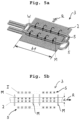
- FIG. 6 a shows a schematic representation of a longitudinal-field module for heating a flat steel strip
- FIG. 6 b shows a schematic representation of the current feed and the magnetic field of a longitudinal-field module for heating a flat steel strip
- FIG. 7 a shows a front view of a third embodiment according to the invention of a heating device
- FIG. 7 b shows a plan view of the heating device from FIG. 7 a
- FIG. 7 c shows a partially sectional representation along the line A-A from FIG. 7 b
- FIG. 8 a shows a schematic representation of a first open-loop or closed-loop control device for the heating device of FIG. 7 a - FIG. 7 c
- FIG. 8 b shows a schematic representation of a second open-loop or closed-loop control device for the heating device of FIG. 7 a - FIG. 7 c
- FIG. 9 shows a schematic plan view of a further embodiment according to the invention of a heating device for heating a flat steel strip
- FIGS. 10 a , 10 b , and 10 c show in each case a schematic representation of a power supply for a heating device according to the invention for heating a flat steel strip.
- FIG. 1 shows a schematic view of a first embodiment, not according to the invention, of a heating device 1 for the inductive heating of a flat steel strip 2 .
- the flat steel strip leaves a roughing train, which is not shown, is heated by means of the heating device 1 and, after the heating, enters a finishing train, which is not shown.
- the heated flat steel strip 2 may also be descaled.
- the heating device 1 comprises eight transverse-field modules 3 .
- a transverse-field module 3 comprises an inductor above and an inductor below the flat steel strip 2 , which generate a magnetic field transversely to the transporting direction R, specifically in the direction of the thickness, and consequently perpendicularly to the upper side and underside of the flat steel strip 2 , and inductively heat it in this way.
- eight transverse-field modules 3 are provided, arranged one after the other. However, a greater or smaller number of transverse-field modules 3 may also be provided.
- the transverse-field modules 3 are operated with alternating voltage of a first frequency f 1 .
- the heating device 1 is suitable for example for heating flat steel strips with thicknesses of 6 mm to 17 mm.
- the flat steel strip 2 can assume different widths b 1 , b 2 .
- the inductors of the transverse-field modules 3 can be moved in relation to an edge, for example the upper inductor, arranged above the strip, may be moved in relation to the edge shown at the top and the lower inductor, arranged below the strip, may be moved in relation to the edge shown at the bottom, in each case by means of an actuator.
- FIG. 2 shows a schematic view of a second embodiment, not according to the invention, of a heating device 1 for the inductive heating of a flat steel strip 2 , in particular for heating between two rolling trains of a hot rolling mill.
- the heating device 1 comprises ten transverse-field modules 3 .
- a transverse-field module 3 once again comprises an inductor above and an inductor below the flat steel strip 2 , which generate a magnetic field transversely to the transporting direction R, specifically in the direction of the thickness, and inductively heat it in this way.
- ten transverse-field modules 3 are provided, arranged one after the other. However, a greater or smaller number of transverse-field modules 3 may also be provided.
- the transverse-field modules 3 are operated with alternating voltage with a switchable frequency, wherein the frequency can assume the value f 1 or the value f 2 , where f 2 is greater than f 1 .
- the heating device 1 is suitable for example for heating flat steel strips with thicknesses of 6 mm to 15 mm, but with an additional possibility for setting the temperature profile.
- FIG. 3 shows a schematic view of a first embodiment according to the invention of a heating device 1 for the inductive heating of a flat steel strip 2 , in particular between two rolling trains of a hot rolling mill.
- the heating device 1 comprises a number of transverse-field modules 3 and longitudinal-field modules 4 , which are arranged one after the other.
- a transverse-field module 3 comprises one or more inductors, which generate a magnetic field transversely to the transporting direction R, specifically in the direction of the thickness of the flat steel strip 2 , and inductively heat it in this way.
- eight transverse-field modules 3 are provided, arranged one after the other. However, a greater or smaller number of transverse-field modules 3 may also be provided.
- a longitudinal-field module 4 comprises one or more inductors, which generate a magnetic field in the longitudinal direction, specifically in the transporting direction R, and consequently parallel to the upper side and underside of the flat steel strip 2 , and inductively heat it in this way.
- four longitudinal-field modules 4 are provided, arranged one after the other. However, a greater or smaller number of longitudinal-field modules 4 may also be provided.
- the transverse-field modules 3 are operated with alternating voltage of a first frequency f 1 .
- the heating device 1 is suitable for example for heating flat steel strips with thicknesses of 6 mm to 20 mm.
- FIG. 4 shows a schematic view of a second embodiment according to the invention of a heating device 1 for the inductive heating of a flat steel strip 2 , in particular for heating between two rolling trains of a hot rolling mill.
- the heating device 1 comprises a number of transverse-field modules 3 and longitudinal-field modules 4 , which are arranged one after the other.
- a transverse-field module 3 comprises one or more inductors, which generate a magnetic field transversely to the transporting direction R, specifically in the direction of the thickness of the flat steel strip 2 , and inductively heat it in this way.
- eight transverse-field modules 3 are provided, arranged one after the other. However, a greater or smaller number of transverse-field modules 3 may also be provided.
- a longitudinal-field module 4 comprises one or more inductors, which generate a magnetic field in the longitudinal direction, specifically in the transporting direction R, and consequently parallel to the upper side and underside of the flat steel strip 2 , and inductively heat it in this way.
- eight longitudinal-field modules 4 are provided, arranged one after the other. However, a greater or smaller number of longitudinal-field modules 4 may also be provided.
- the transverse-field modules 3 are operated with alternating voltage with a switchable frequency, wherein the frequency can assume the value f 1 or the value f 2 , where f 2 is greater than f 1 .
- the longitudinal-field modules 4 are operated either with a frequency f 3 or f 4 , where f 3 >f 2 and f 4 >f 2 .
- the heating device 1 is suitable for example for heating flat steel strips with thicknesses of 6 mm to 65 mm.
- FIG. 5 a schematically shows a transverse-field module 3 with two coils 5 , which are arranged above and below the flat steel strip 2 .
- a magnetic field M forms transversely to the transporting direction R in the direction of the thickness of the strip 2 .
- Eddy currents W form on the upper side and the underside of the strip 2 .
- FIG. 5 b the current feed I (currents running into the plane of the drawing are shown by a cross, currents running out of the plane of the drawing are shown by a dot) of the coils 5 and the magnetic flux lines of the magnetic field M for a further transverse-field module 3 are shown.
- FIG. 6 a schematically shows a longitudinal-field module 4 with a coil 5 , which encloses the flat steel strip 2 transversely to the transporting direction R.
- a magnetic field M forms in the transporting direction R parallel to the upper side and the underside of the strip 2 .
- Eddy currents W form parallel to the upper side and the underside of the strip 2 .
- FIG. 6 b the current feed I (currents running into the plane of the drawing are shown by a cross, currents running out of the plane of the drawing are shown by a dot) of the coil 5 and the magnetic flux lines of the magnetic field M for a longitudinal-field module 4 are shown.
- FIGS. 7 a and 7 b show an elevation and a plan view of a heating device 1 according to the invention in a hot rolling mill.
- the width b, the thickness d, the speed v and the temperature profile T 1 of the preliminary strip 2 are measured by suitable measuring instruments after the last stand 9 of the roughing train and are fed to an open-loop or closed-loop control device 8 (see FIG. 8 a ).
- the preliminary strip 2 is descaled under high pressure, for example 150 to 400 bar, by two descalers 12 .
- Respectively arranged before and after the descalers is a pair of driver rollers 13 to prevent the escape of pressurized water from the descaling region.
- the temperature profile T 2 of the preliminary strip is measured by a pyrometer 11 and likewise fed to the open-loop or closed-loop control device 8 .
- a pyrometer 11 shown by dashed lines, which measures the temperature profile of the preliminary strip 2 before the descalers.
- the coils 5 of the transverse-field modules 3 are in each case accommodated in a coil car 19 (also see FIG. 7 c ).
- the coil car 19 together with the coils 5 above and below the preliminary strip 2 can be moved by means of a thrust actuator 6 in the direction of the width of the preliminary strip.
- the width position 5 B i.e. the distance between a side edge of the preliminary strip 2 and the end of the coil 5 , can be set.
- the height position s H of the coils 5 can be changed.
- the changing of the height is performed by multiple lift actuators 7 (also see FIG. 7 c ).
- the power supply 14 of one or more transverse-field modules 3 is accommodated in a climatically controlled and clean electrical compartment 20 .
- FIG. 7 c schematically shows a section transversely to the transporting direction R along the line A-A from FIG.
- the power supply 14 has a frequency input for determining a setpoint frequency f Soll , a current input for determining a setpoint current intensity I Soll , a width input for determining a setpoint width position s B-Soll and a height input for determining a setpoint height position s H-Soll .
- These inputs can be used to adapt one or more transverse-field modules 3 to the current production conditions with regard to the frequency f and the current intensity I of the alternating voltage and also with regard to the width position s B and the height position s H .
- FIG. 7 b only a single power supply 14 is shown. It goes without saying that all of the transverse-field modules 3 are connected to power supplies 14 , wherein a power supply 14 can supply one or more transverse-field modules 3 .
- the power supply of the longitudinal-field modules 4 has not been shown.
- FIGS. 8 a and 8 b each show a diagram of an open-loop or closed-loop control device 8 , which is continually fed current data of the production process, such as the width b, the thickness d, the speed v of the preliminary strip and also the temperature profiles T 1 of the preliminary strip 2 before entering the heating device 1 and after leaving the heating device 1 .
- the open-loop or closed-loop control device 8 calculates from these input variables the setpoint frequency f Soll and the setpoint current intensity I Soll for the power supplies 14 and also the setpoint width position s B-Soll and the setpoint height position s H-Soll for the coil cars 19 of the transverse-field modules.
- FIG. 8 a the open-loop or closed-loop control device 8 calculates from these input variables the setpoint frequency f Soll and the setpoint current intensity I Soll for the power supplies 14 and also the setpoint width position s B-Soll and the setpoint height position s H-Soll for the coil cars 19 of the transverse-field
- the open-loop or closed-loop control device 8 calculates from these input variables the setpoint voltage U Soll and the setpoint heating power P Soll for the power supplies 14 of the longitudinal-field modules.
- the setpoint values are connected in terms of signaling by way of the respective outputs of the open-loop or closed-loop control device 8 to the inputs of the power supply or the inputs on the transverse-field modules.
- the open-loop or closed-loop control device 8 may be for example a PLC or a process computer. It is also possible that the functionality of the open-loop or closed-loop control device 8 is taken over by the plant controller of the rolling plant.
- FIG. 9 schematically shows a plan view of a heating device according to the invention with four transverse-field modules 3 and four longitudinal-field modules 4 and also the associated power supplies 14 a , 14 b.
- FIG. 10 a a first variant of a power supply 14 a , 14 b is schematically shown.
- the converter 16 is a load-commutated converter, which sets the frequency f of the generated alternating voltage in dependence on the load, specifically the capacitive load of the capacitor bank 17 and the inductive load of the coils 5 .
- the first capacitor, shown on the left, with the capacitance C can be activated or deactivated by means of a switch, which is switched in dependence on a frequency input 22 . In the activated state, the frequency f is obtained as
- the voltage amplitude U or the setpoint heating power P can be determined for the converter.
- FIG. 10 b a second variant of a power supply 14 a , 14 b is schematically shown.
- the converter 16 is of an identical configuration to the converter from FIG. 10 a .
- the capacitors of the capacitor bank 17 may however not be switched. However, current may be fed to either one or two coils 5 . In one case, the frequency f is obtained as
- the voltage amplitude U or the setpoint heating power P can be determined for the converter.
- inductances and capacitances in a circuit may be activated or deactivated.
- FIG. 10 c finally shows a third variant of a power supply 14 a , 14 b with a non-load-commutated or externally commutated converter 16 .
- the load is 2 C for the capacitor bank 17 and L for the coil 5 .
- the frequency f of the alternating voltage would be obtained as
- the actual frequency f of the alternating voltage may deviate from f 0 , because f is determined directly for the converter 16 by a frequency input 22 .
- the power supply must feed not only the heating power but also the reactive power to the converter.
- f 0 denotes the resonant frequency of a so-called LC resonant circuit.
- FIGS. 10 a . . . 10 c are schematic and do not take into account the magnetic coupling between the coil or the coils 5 and the flat steel strip 2 .
- Heating device Flat steel strip, preliminary strip 3 Transverse-field module 4 Longitudinal-field module 5 Coil 6 Thrust actuator 7 Lift actuator 8 Open-loop or closed-loop control device 9 Stand of the roughing train 10 Stand of the finishing train 11 Thermometer or pyrometer 12 Descalers 13 Driving roller 14, 14a, 14b Power supply 15 Flexible cable 16 Converter 16a Converter cabinet 17 Capacitor bank 18 Conductor rail 19 Coil car 20 Electrical compartment 21 Explosion flap 22 Frequency input 23 Switch b, b1, b2 Width of the flat steel strip C Capacitance d Thickness of the flat steel strip f, f1, f2, f3, f4 Frequency, actual frequency f 0 Resonant frequency of an LC resonant circuit f Soll Setpoint frequency M Magnetic flux I Current, current intensity, actual current intensity I Soll Setpoint current L Inductance P Power R Transporting direction S B Width position of the coil, actual width pos. S B-Soll Setpoint width position of the coil S H
Landscapes
- Engineering & Computer Science (AREA)
- Mechanical Engineering (AREA)
- Chemical & Material Sciences (AREA)
- Physics & Mathematics (AREA)
- Thermal Sciences (AREA)
- Crystallography & Structural Chemistry (AREA)
- Materials Engineering (AREA)
- Metallurgy (AREA)
- Organic Chemistry (AREA)
- General Induction Heating (AREA)
- Heat Treatment Of Strip Materials And Filament Materials (AREA)
- Metal Rolling (AREA)
Applications Claiming Priority (6)
| Application Number | Priority Date | Filing Date | Title |
|---|---|---|---|
| ATA50273/2019 | 2019-03-29 | ||
| ATA50273/2019A AT522345B1 (de) | 2019-03-29 | 2019-03-29 | Heizungsvorrichtung zum induktiven Erhitzen eines Flachstahlstreifens in einem Warmwalzwerk |
| EP19177246.6A EP3715001B1 (de) | 2019-03-29 | 2019-05-29 | Heizungsvorrichtung zum induktiven erhitzen eines flachstahlstreifens in einem warmwalzwerk |
| EP19177246.6 | 2019-05-29 | ||
| EP19177246 | 2019-05-29 | ||
| PCT/EP2020/055681 WO2020200612A1 (de) | 2019-03-29 | 2020-03-04 | Heizungsvorrichtung zum induktiven erhitzen eines flachstahlstreifens in einem warmwalzwerk |
Publications (2)
| Publication Number | Publication Date |
|---|---|
| US20220193741A1 US20220193741A1 (en) | 2022-06-23 |
| US12090535B2 true US12090535B2 (en) | 2024-09-17 |
Family
ID=66676352
Family Applications (1)
| Application Number | Title | Priority Date | Filing Date |
|---|---|---|---|
| US17/599,088 Active 2040-07-10 US12090535B2 (en) | 2019-03-29 | 2020-03-04 | Heating device for the inductive heating of a flat steel strip in a hot rolling mill |
Country Status (6)
| Country | Link |
|---|---|
| US (1) | US12090535B2 (de) |
| EP (1) | EP3715001B1 (de) |
| CN (1) | CN113613808B (de) |
| AT (1) | AT522345B1 (de) |
| ES (1) | ES2985281T3 (de) |
| WO (1) | WO2020200612A1 (de) |
Cited By (1)
| Publication number | Priority date | Publication date | Assignee | Title |
|---|---|---|---|---|
| US20230241657A1 (en) * | 2020-07-15 | 2023-08-03 | Primetals Technologies Austria GmbH | Method and installation for inductively heating flat objects |
Families Citing this family (14)
| Publication number | Priority date | Publication date | Assignee | Title |
|---|---|---|---|---|
| AT522345B1 (de) * | 2019-03-29 | 2020-11-15 | Primetals Technologies Austria GmbH | Heizungsvorrichtung zum induktiven Erhitzen eines Flachstahlstreifens in einem Warmwalzwerk |
| DE102021204433A1 (de) | 2021-05-03 | 2022-11-03 | Sms Group Gmbh | Verfahren zum Walzen eines ringförmigen Walzguts mit einem offenen zylindrischen Querschnitt in einer Ringwalzmaschine sowie Ringwalzmaschine zur Durchführung des Verfahrens |
| CN113296463A (zh) * | 2021-05-17 | 2021-08-24 | 潍坊特钢集团有限公司 | 一种金属方坯加工装置的控制系统及其实现方法 |
| CN113695403B (zh) * | 2021-08-09 | 2022-08-23 | 燕山大学 | 一种基于温度均匀控制的无头轧制方法 |
| CN115213243B (zh) * | 2022-07-21 | 2024-05-14 | 辽宁科技大学 | 一种钢坯加热装置及方法 |
| DE102023113618A1 (de) * | 2023-05-24 | 2024-11-28 | Sms Group Gmbh | Induktionsheizvorrichtung, Betriebsverfahren, Produktionslinie, Verwendung einer derartigen Induktionsheizvorrichtung, Verwendung eines derartigen Betriebsverfahrens sowie Verwendung einer derartigen Produktionslinie |
| DE102023113617A1 (de) * | 2023-05-24 | 2024-11-28 | Sms Group Gmbh | Induktionsheizvorrichtung, Betriebsverfahren, Produktionslinie, Verwendung einer derartigen Induktionsheizvorrichtung, Verwendung eines derartigen Betriebsverfahrens sowie Verwendung einer derartigen Produktionslinie |
| DE102023113619A1 (de) * | 2023-05-24 | 2024-11-28 | Sms Group Gmbh | System, Induktionsheizvorrichtung, Produktionslinie, Nachrüst-Kit und Verwendung eines Steuerungssystems |
| DE102023115847A1 (de) * | 2023-06-16 | 2024-12-19 | Sms Group Gmbh | Induktionsheizvorrichtung, Produktionslinie, Verfahren zum induktiven Erwärmen und Verwendung einer Oberfläche |
| DE102023135183A1 (de) | 2023-12-14 | 2025-06-18 | Friedrich-Alexander-Universität Erlangen-Nürnberg, in Vertretung des Freistaates Bayern | Vorrichtung und Verfahren zur Herstellung eines Folienverbunds |
| DE102024101157A1 (de) * | 2024-01-16 | 2025-07-17 | Sms Group Gmbh | Verfahren zum Erwärmen eines metallischen Gutes, Induktionsheizvorrichtung, Produktionslinie und Verwendung einer derartigen Induktionsheizvorrichtung |
| DE102024101160A1 (de) * | 2024-01-16 | 2025-07-17 | Sms Group Gmbh | Steuer- und/oder Regeleinheit, Induktorensystem, Produktionslinie und Verwendung |
| DE102024103010A1 (de) * | 2024-02-02 | 2025-08-07 | Sms Group Gmbh | Induktionserwärmungsvorrichtung, Verfahren, Produktionslinie, Verwendung einer derartigen Induktionserwärmungsvorrichtung, Verwendung eines derartigen Verfahrens sowie Verwendung einer derartigen Produktionslinie |
| DE102024105327A1 (de) * | 2024-02-26 | 2025-08-28 | Sms Group Gmbh | Produktionslinie zur Herstellung und/oder Verarbeitung von metallischen Werkstücken |
Citations (24)
| Publication number | Priority date | Publication date | Assignee | Title |
|---|---|---|---|---|
| US2448011A (en) * | 1944-09-09 | 1948-08-31 | Westinghouse Electric Corp | Method and apparatus for induction heating of metal strips |
| DE2704451A1 (de) | 1976-02-06 | 1977-08-11 | Nippon Steel Corp | Verfahren zur kontinuierlichen induktiven erhitzung von langgestreckten metallwerkstuecken |
| SU847528A1 (ru) | 1979-04-23 | 1981-07-15 | Куйбышевский Политехнический Институтим. B.B.Куйбышева | Способ термообработки металлическихиздЕлий B иНдуКТОРЕ |
| SU1031006A1 (ru) | 1982-04-13 | 1983-07-23 | Московский Ордена Ленина И Ордена Октябрьской Революции Энергетический Институт | Индукционна нагревательна установка |
| RU2032996C1 (ru) | 1991-07-03 | 1995-04-10 | Самарский государственный технический университет | Устройство для управления температурой плоской заготовки при индукционном нагреве |
| RU2039420C1 (ru) | 1991-03-11 | 1995-07-09 | Самарский государственный технический университет | Способ индукционного нагрева плоских металлических изделий |
| JPH0866302A (ja) | 1994-08-31 | 1996-03-12 | Sanyo Electric Co Ltd | 誘導加熱装置とその入力電力特性調整方法 |
| US6265701B1 (en) | 1998-03-31 | 2001-07-24 | Illinois Tool Works Inc. | Method and apparatus for inductive preheating and welding along a weld path |
| DE102006002505A1 (de) | 2005-10-31 | 2007-05-03 | Sms Demag Ag | Verfahren und Fertigwalzstraße zum Warmwalzen von Eingangsmaterial |
| RU2317657C2 (ru) | 2005-10-19 | 2008-02-20 | Федеральное государственное унитарное предприятие "Центральное конструкторское бюро "Геофизика" | Индукционная установка |
| AT507663A4 (de) | 2009-04-09 | 2010-07-15 | Siemens Vai Metals Tech Gmbh | Verfahren und vorrichtung zum aufbereiten von warmwalzgut |
| RU2406275C2 (ru) | 2005-09-07 | 2010-12-10 | Франц Хаймер Машиненбау Кг | Электрическая схема, зажимное крепление и способ управления |
| WO2011038965A1 (de) | 2009-09-29 | 2011-04-07 | Siemens Aktiengesellschaft | Verfahren zur modellbasierten ermittlung von stellglied-sollwerten für die asymmetrischen stellglieder der walzgerüste einer warmbreitbandstrasse |
| US20110284527A1 (en) | 2010-05-21 | 2011-11-24 | Illinois Tool Works Inc. | Auxiliary welding heating system |
| RU2449510C1 (ru) | 2008-04-09 | 2012-04-27 | Ниппон Стил Корпорейшн | Устройство и способ индукционного нагрева |
| CN103068502A (zh) | 2010-08-13 | 2013-04-24 | 西门子公司 | 借助于铸坯直接轧制联合装置制造轧件的方法,用于铸坯直接轧制联合装置的控制装置和/或调节装置和铸坯直接轧制联合装置 |
| DE102013224547A1 (de) | 2013-11-29 | 2015-06-03 | Sms Siemag Ag | Vorrichtung zur Temperaturerhöhung von länglichem metallischem Walzgut und Fertigstraße zum Erzeugen und/oder Bearbeiten von länglichem metallischem Walzgut |
| EP3025799A1 (de) | 2014-11-28 | 2016-06-01 | SMS group GmbH | Walzanlage, Gieß-Walz-Anlage und Verfahren zum Erzeugen eines Metallbandes |
| RU172183U1 (ru) | 2016-10-25 | 2017-06-30 | Общество с ограниченной ответственностью "НПП Система 48" | Устройство для управления индуктором |
| EP3284546A1 (de) | 2016-08-19 | 2018-02-21 | SMS Group GmbH | Verfahren zum walzen eines walzguts in einer walzstrasse und walzstrasse |
| DE102016224822A1 (de) | 2016-08-19 | 2018-02-22 | Sms Group Gmbh | Verfahren zum Walzen eines Walzguts in einer Walzstraße und Walzstraße |
| CN108413774A (zh) | 2018-05-11 | 2018-08-17 | 浙江豪科精工技术有限公司 | 一种轴承制造用加热装置 |
| DE102017212529A1 (de) | 2017-07-20 | 2019-01-24 | Sms Group Gmbh | Verfahren zur Herstellung eines metallischen Bandes |
| US20220193741A1 (en) * | 2019-03-29 | 2022-06-23 | Primetals Technologies Austria GmbH | Heating device for the inductive heating of a flat steel strip in a hot rolling mill |
-
2019
- 2019-03-29 AT ATA50273/2019A patent/AT522345B1/de active
- 2019-05-29 ES ES19177246T patent/ES2985281T3/es active Active
- 2019-05-29 EP EP19177246.6A patent/EP3715001B1/de active Active
-
2020
- 2020-03-04 CN CN202080026191.2A patent/CN113613808B/zh active Active
- 2020-03-04 WO PCT/EP2020/055681 patent/WO2020200612A1/de not_active Ceased
- 2020-03-04 US US17/599,088 patent/US12090535B2/en active Active
Patent Citations (30)
| Publication number | Priority date | Publication date | Assignee | Title |
|---|---|---|---|---|
| US2448011A (en) * | 1944-09-09 | 1948-08-31 | Westinghouse Electric Corp | Method and apparatus for induction heating of metal strips |
| DE2704451A1 (de) | 1976-02-06 | 1977-08-11 | Nippon Steel Corp | Verfahren zur kontinuierlichen induktiven erhitzung von langgestreckten metallwerkstuecken |
| SU847528A1 (ru) | 1979-04-23 | 1981-07-15 | Куйбышевский Политехнический Институтим. B.B.Куйбышева | Способ термообработки металлическихиздЕлий B иНдуКТОРЕ |
| SU1031006A1 (ru) | 1982-04-13 | 1983-07-23 | Московский Ордена Ленина И Ордена Октябрьской Революции Энергетический Институт | Индукционна нагревательна установка |
| RU2039420C1 (ru) | 1991-03-11 | 1995-07-09 | Самарский государственный технический университет | Способ индукционного нагрева плоских металлических изделий |
| RU2032996C1 (ru) | 1991-07-03 | 1995-04-10 | Самарский государственный технический университет | Устройство для управления температурой плоской заготовки при индукционном нагреве |
| JPH0866302A (ja) | 1994-08-31 | 1996-03-12 | Sanyo Electric Co Ltd | 誘導加熱装置とその入力電力特性調整方法 |
| US6265701B1 (en) | 1998-03-31 | 2001-07-24 | Illinois Tool Works Inc. | Method and apparatus for inductive preheating and welding along a weld path |
| US8102682B2 (en) | 2005-09-07 | 2012-01-24 | Franz Haimer Maschinebau KG | Power supply control circuit for an inductive coil used to heat a tool shrink attachment |
| RU2406275C2 (ru) | 2005-09-07 | 2010-12-10 | Франц Хаймер Машиненбау Кг | Электрическая схема, зажимное крепление и способ управления |
| RU2317657C2 (ru) | 2005-10-19 | 2008-02-20 | Федеральное государственное унитарное предприятие "Центральное конструкторское бюро "Геофизика" | Индукционная установка |
| DE102006002505A1 (de) | 2005-10-31 | 2007-05-03 | Sms Demag Ag | Verfahren und Fertigwalzstraße zum Warmwalzen von Eingangsmaterial |
| RU2449510C1 (ru) | 2008-04-09 | 2012-04-27 | Ниппон Стил Корпорейшн | Устройство и способ индукционного нагрева |
| US8420990B2 (en) | 2008-04-09 | 2013-04-16 | Nippon Steel & Sumitomo Metal Corporation | Induction heating apparatus and induction heating method |
| US8950227B2 (en) | 2009-04-09 | 2015-02-10 | Siemens Vai Metals Technologies Gmbh | Method and device for preparing hot-rolling stock |
| AT507663A4 (de) | 2009-04-09 | 2010-07-15 | Siemens Vai Metals Tech Gmbh | Verfahren und vorrichtung zum aufbereiten von warmwalzgut |
| CN102387874A (zh) | 2009-04-09 | 2012-03-21 | 西门子Vai金属科技有限责任公司 | 制备热轧件的方法和装置 |
| US20120067095A1 (en) | 2009-04-09 | 2012-03-22 | Gerald Hohenbichler | Method and device for preparing hot-rolling stock |
| WO2011038965A1 (de) | 2009-09-29 | 2011-04-07 | Siemens Aktiengesellschaft | Verfahren zur modellbasierten ermittlung von stellglied-sollwerten für die asymmetrischen stellglieder der walzgerüste einer warmbreitbandstrasse |
| US20110284527A1 (en) | 2010-05-21 | 2011-11-24 | Illinois Tool Works Inc. | Auxiliary welding heating system |
| CN103068502A (zh) | 2010-08-13 | 2013-04-24 | 西门子公司 | 借助于铸坯直接轧制联合装置制造轧件的方法,用于铸坯直接轧制联合装置的控制装置和/或调节装置和铸坯直接轧制联合装置 |
| US9855598B2 (en) | 2010-08-13 | 2018-01-02 | Siemens Aktiengesellschaft | Method for producing rolling stock by means of a combined continuous casting and rolling system, control device for a combined continuous casting and rolling system, and combined continuous casting and rolling system |
| DE102013224547A1 (de) | 2013-11-29 | 2015-06-03 | Sms Siemag Ag | Vorrichtung zur Temperaturerhöhung von länglichem metallischem Walzgut und Fertigstraße zum Erzeugen und/oder Bearbeiten von länglichem metallischem Walzgut |
| EP3025799A1 (de) | 2014-11-28 | 2016-06-01 | SMS group GmbH | Walzanlage, Gieß-Walz-Anlage und Verfahren zum Erzeugen eines Metallbandes |
| EP3284546A1 (de) | 2016-08-19 | 2018-02-21 | SMS Group GmbH | Verfahren zum walzen eines walzguts in einer walzstrasse und walzstrasse |
| DE102016224822A1 (de) | 2016-08-19 | 2018-02-22 | Sms Group Gmbh | Verfahren zum Walzen eines Walzguts in einer Walzstraße und Walzstraße |
| RU172183U1 (ru) | 2016-10-25 | 2017-06-30 | Общество с ограниченной ответственностью "НПП Система 48" | Устройство для управления индуктором |
| DE102017212529A1 (de) | 2017-07-20 | 2019-01-24 | Sms Group Gmbh | Verfahren zur Herstellung eines metallischen Bandes |
| CN108413774A (zh) | 2018-05-11 | 2018-08-17 | 浙江豪科精工技术有限公司 | 一种轴承制造用加热装置 |
| US20220193741A1 (en) * | 2019-03-29 | 2022-06-23 | Primetals Technologies Austria GmbH | Heating device for the inductive heating of a flat steel strip in a hot rolling mill |
Non-Patent Citations (5)
| Title |
|---|
| Anis Abdurahman et al: "Einsatz flexibler Induktionseinheiten zur Produktions—und Qualitätserhöhung in Warmwalzwerken", E Lektrowarme International, Feb. 1, 2012 (Feb. 1, 2012), pp. 47-51, XP055467400; 2012. |
| European Search Report received in European Application No. 19177246.6 dated Jan. 22, 2020, pp. 6. |
| International Search Report and Written Opinion received in International Application No. PCT/EP2020/055681 dated May 19, 2020, pp. 13. |
| Office Action and Search Report received in Chinese Application No. 202080026191.2 dated Jan. 13, 2023, pp. 13. |
| Office Action received in Russian Application No. 2021118671/05(039330) dated Jan. 17, 2022, pp. 19. |
Cited By (1)
| Publication number | Priority date | Publication date | Assignee | Title |
|---|---|---|---|---|
| US20230241657A1 (en) * | 2020-07-15 | 2023-08-03 | Primetals Technologies Austria GmbH | Method and installation for inductively heating flat objects |
Also Published As
| Publication number | Publication date |
|---|---|
| WO2020200612A1 (de) | 2020-10-08 |
| ES2985281T3 (es) | 2024-11-04 |
| EP3715001A1 (de) | 2020-09-30 |
| AT522345A1 (de) | 2020-10-15 |
| EP3715001B1 (de) | 2024-06-26 |
| EP3715001C0 (de) | 2024-06-26 |
| AT522345B1 (de) | 2020-11-15 |
| CN113613808A (zh) | 2021-11-05 |
| CN113613808B (zh) | 2024-03-26 |
| US20220193741A1 (en) | 2022-06-23 |
Similar Documents
| Publication | Publication Date | Title |
|---|---|---|
| US12090535B2 (en) | Heating device for the inductive heating of a flat steel strip in a hot rolling mill | |
| KR101138725B1 (ko) | 폭에 걸친 온도 분포에 영향을 주기 위한 장치 | |
| US6180933B1 (en) | Furnace with multiple electric induction heating sections particularly for use in galvanizing line | |
| JP5137842B2 (ja) | 導入材料の熱間圧延をするための方法及び仕上げ圧延ライン | |
| CN100333846C (zh) | 热钢板的热轧方法和装置 | |
| CN113102504B (zh) | 生产扁平金属产品的方法和设备 | |
| KR100627183B1 (ko) | 트랜스버스형 유도 가열 장치 | |
| CN103890216A (zh) | 镁材辊轧机 | |
| BG60468B1 (bg) | Индукционна пещ за нагряване и хомогенизиране на температурата при горещо валцуване на тънки стоманени ленти | |
| CN117000763A (zh) | 柔性精轧机组、连铸连轧柔性生产线以及对应的生产方法 | |
| CN1230333A (zh) | 在摆动式感应加热炉中加热金属产品的系统、装置及方法 | |
| US20070051152A1 (en) | Device for heating a metal strip, and apparatuses equipped with a device of this type, for producing hot-rolled metal strip | |
| CN115803465B (zh) | 用于以感应方式加热扁形件的方法和设施 | |
| JP3418739B2 (ja) | 連続鋳造熱延設備および連続鋳造熱延方法 | |
| CN118043146A (zh) | 用于制造扁平轧材的系统和方法 | |
| RU2779350C1 (ru) | Нагревательное устройство для индуктивного нагрева плоской стальной полосы в стане горячей прокатки | |
| US20250129444A1 (en) | System and method for producing flat rolled products | |
| AU2016377688A1 (en) | High frequency power supply system with closely regulated output for heating a workpiece | |
| CN101310029B (zh) | 用于热轧输入材料的方法和精轧机 | |
| JP3620464B2 (ja) | 熱延鋼板の製造方法および製造装置 | |
| JP2023548661A (ja) | 熱間圧延された金属帯板を製造する装置及び方法 | |
| US20250050397A1 (en) | Plant and method for producing flat rolled products | |
| CN120958946A (zh) | 感应加热装置、生产线、感应加热方法和表面应用 | |
| JP3960204B2 (ja) | 熱延鋼帯の製造方法 | |
| MX2008005516A (en) | Method and finishing train for hot-rolling starting material |
Legal Events
| Date | Code | Title | Description |
|---|---|---|---|
| AS | Assignment |
Owner name: PRIMETALS TECHNOLOGIES AUSTRIA GMBH, AUSTRIA Free format text: ASSIGNMENT OF ASSIGNORS INTEREST;ASSIGNORS:LENGAUER, THOMAS;LINZER, BERND;ZAHEDI, MICHAEL;REEL/FRAME:057623/0530 Effective date: 20210512 |
|
| FEPP | Fee payment procedure |
Free format text: ENTITY STATUS SET TO UNDISCOUNTED (ORIGINAL EVENT CODE: BIG.); ENTITY STATUS OF PATENT OWNER: LARGE ENTITY |
|
| STPP | Information on status: patent application and granting procedure in general |
Free format text: DOCKETED NEW CASE - READY FOR EXAMINATION |
|
| STPP | Information on status: patent application and granting procedure in general |
Free format text: NON FINAL ACTION MAILED |
|
| STPP | Information on status: patent application and granting procedure in general |
Free format text: RESPONSE TO NON-FINAL OFFICE ACTION ENTERED AND FORWARDED TO EXAMINER |
|
| STPP | Information on status: patent application and granting procedure in general |
Free format text: FINAL REJECTION MAILED |
|
| STPP | Information on status: patent application and granting procedure in general |
Free format text: RESPONSE AFTER FINAL ACTION FORWARDED TO EXAMINER |
|
| STPP | Information on status: patent application and granting procedure in general |
Free format text: ADVISORY ACTION MAILED |
|
| STCV | Information on status: appeal procedure |
Free format text: NOTICE OF APPEAL FILED |
|
| STCV | Information on status: appeal procedure |
Free format text: APPEAL BRIEF (OR SUPPLEMENTAL BRIEF) ENTERED AND FORWARDED TO EXAMINER |
|
| STPP | Information on status: patent application and granting procedure in general |
Free format text: NOTICE OF ALLOWANCE MAILED -- APPLICATION RECEIVED IN OFFICE OF PUBLICATIONS |
|
| STPP | Information on status: patent application and granting procedure in general |
Free format text: PUBLICATIONS -- ISSUE FEE PAYMENT RECEIVED |
|
| STPP | Information on status: patent application and granting procedure in general |
Free format text: PUBLICATIONS -- ISSUE FEE PAYMENT VERIFIED |
|
| STCF | Information on status: patent grant |
Free format text: PATENTED CASE |