US11834837B2 - Louver awning with hidden louver opening and closing driving structure - Google Patents
Louver awning with hidden louver opening and closing driving structure Download PDFInfo
- Publication number
- US11834837B2 US11834837B2 US17/425,732 US202117425732A US11834837B2 US 11834837 B2 US11834837 B2 US 11834837B2 US 202117425732 A US202117425732 A US 202117425732A US 11834837 B2 US11834837 B2 US 11834837B2
- Authority
- US
- United States
- Prior art keywords
- louver
- transmission
- transmission mechanism
- rotate
- awning
- Prior art date
- Legal status (The legal status is an assumption and is not a legal conclusion. Google has not performed a legal analysis and makes no representation as to the accuracy of the status listed.)
- Active, expires
Links
- 230000005540 biological transmission Effects 0.000 claims abstract description 227
- 239000004744 fabric Substances 0.000 claims description 8
- 238000010586 diagram Methods 0.000 description 7
- 238000005457 optimization Methods 0.000 description 7
- 239000000463 material Substances 0.000 description 5
- 239000004677 Nylon Substances 0.000 description 2
- 230000009286 beneficial effect Effects 0.000 description 2
- 229920001778 nylon Polymers 0.000 description 2
- 229920003229 poly(methyl methacrylate) Polymers 0.000 description 2
- 239000004926 polymethyl methacrylate Substances 0.000 description 2
- 230000001360 synchronised effect Effects 0.000 description 2
- 230000000712 assembly Effects 0.000 description 1
- 238000000429 assembly Methods 0.000 description 1
- 230000003796 beauty Effects 0.000 description 1
- 230000004048 modification Effects 0.000 description 1
- 238000012986 modification Methods 0.000 description 1
- 238000006467 substitution reaction Methods 0.000 description 1
Images


Classifications
-
- E—FIXED CONSTRUCTIONS
- E04—BUILDING
- E04F—FINISHING WORK ON BUILDINGS, e.g. STAIRS, FLOORS
- E04F10/00—Sunshades, e.g. Florentine blinds or jalousies; Outside screens; Awnings or baldachins
-
- E—FIXED CONSTRUCTIONS
- E04—BUILDING
- E04F—FINISHING WORK ON BUILDINGS, e.g. STAIRS, FLOORS
- E04F10/00—Sunshades, e.g. Florentine blinds or jalousies; Outside screens; Awnings or baldachins
- E04F10/08—Sunshades, e.g. Florentine blinds or jalousies; Outside screens; Awnings or baldachins of a plurality of similar rigid parts, e.g. slabs, lamellae
- E04F10/10—Sunshades, e.g. Florentine blinds or jalousies; Outside screens; Awnings or baldachins of a plurality of similar rigid parts, e.g. slabs, lamellae collapsible or extensible; metallic Florentine blinds; awnings with movable parts such as louvres
Definitions
- the invention relates to the field of outdoor products, and in particular to a louver awning with a hidden blind opening and closing driving structure.
- the louver awning is a common outdoor product.
- the Chinese patent publication CN111794457A discloses a tent with a central driving long louver roof opening and closing structure.
- the tent includes an awning frame, a louver group, linkage bars, a louver transmission mechanism, a transmission rod and a driving structure.
- the awning frame includes two first ring beams and a middle beam.
- the louver group includes a group of louvers provided in rows, and both ends of the louvers are fitted with the two first ring beams through a first mounting assembly.
- the middle part of the louver is fitted with the middle beam through a second mounting assembly, and the mounting assemblies comprise a louver fixing seat and a louver rotating part.
- the tent has the following beneficial effects: the driving structure is mounted on the middle beam, and the driving structure drives the louver transmission mechanism on both sides to open and close the louvers, so that the louvers can be prevented from being twisted.
- the louver fixing seat is clamped to be assembled with the first ring beam and the middle beam, so that the assembly mode of the louver is simplified, and the labor cost and the material cost are reduced.
- the louver driving structure in the louver awning is exposed in the middle of the louver awning, which is very conspicuous and not concise in form, so it affects the beauty, and also occupies the space in the awning and affects the use of the louver awning.
- the present invention provides a technical scheme of a louver awning with a hidden blind opening and closing driving structure.
- the louver awning with a hidden louver opening and closing driving structure includes an awning frame assembly, a plurality of louvers rotatably mounted on a top portion of the awning frame assembly, linkage bars for linking the plurality of louvers, and a louver opening and closing driving structure for driving the louvers to open and close.
- the awning frame assembly comprises a plurality of columns and ring beams fitted together.
- the louver opening and closing driving structure comprises a hand-operated mechanism fitted on one of the columns, a transmission assembly transmissively coupled to the hand-operated mechanism and a louver transmission mechanism transmissively coupled to the transmission assembly.
- the transmission assembly is used to transmit power input by the hand-operated mechanism to the louver transmission mechanism, and the louver transmission mechanism is used to drive the louvers to rotate so as to realize opening and closing of the louvers.
- the louver awning with a hidden louver opening and closing driving structure is characterized by further comprising a crank connecting rod mechanism.
- the crank connecting rod mechanism comprises a crank and a connecting rod rotatably coupled to the crank.
- the crank is used to be transmissively coupled to a second transmission assembly, and the connecting rod is used to be rotatably coupled to the louver.
- the crank is capable of driving the louver to rotate through the connecting rod, so as to realize the opening and closing of the louver.
- the louver awning with a hidden louver opening and closing driving structure is characterized in that the transmission assembly comprises a first transmission mechanism transmissively coupled to the hand-operated mechanism, a first transmission rod transmissively coupled to the first transmission mechanism and vertically arranged, and a second transmission mechanism transmissively coupled to an upper end of the first transmission rod.
- the hand-operated mechanism is used to drive the first transmission mechanism to rotate
- the first transmission mechanism is used to drive the first transmission rod to rotate
- the first transmission rod is used to drive the second transmission mechanism to rotate
- the second transmission mechanism is used to drive the louver transmission mechanism to rotate.
- the louver awning with a hidden louver opening and closing driving structure is characterized in that the hand-operated mechanism is fitted on a side of the one of the columns, and the first transmission mechanism, the first transmission rod and the second transmission mechanism are fitted in the one of the columns.
- the louver awning with a hidden blind opening and closing driving structure is characterized in that the transmission assembly comprises a first transmission mechanism transmissively coupled to the hand-operated mechanism, a first transmission rod transmissively coupled to the first transmission mechanism and vertically arranged, a third transmission mechanism transmissively coupled to the first transmission rod, a second transmission rod transmissively coupled to the third transmission mechanism and horizontally arranged, and a fourth transmission mechanism transmissively coupled to the second transmission rod.
- the hand-operated mechanism is used to drive the first transmission mechanism to rotate, the first transmission mechanism is used to drive the first transmission rod to rotate, the first transmission rod is used to drive the third transmission mechanism to rotate, the third transmission mechanism is used to drive the second transmission rod to rotate, the second transmission rod is used to drive the fourth transmission mechanism to rotate, and the fourth transmission mechanism is used to drive the louver transmission mechanism to rotate.
- the louver awning with a hidden louver opening and closing driving structure is characterized in that the hand-operated mechanism is fitted on a side of the one of the columns, the first transmission mechanism and the first transmission rod are fitted in the column, and the second transmission rod and the fourth transmission mechanism are fitted in one of the ring beams.
- the louver awning with a hidden louver opening and closing driving structure is characterized in that an upper end of each column is fitted with a first profile connector, an end of each ring beam is fitted with a second profile connector, and the first profile connector and the second profile connector are fastened and combined through a protruding and recess structure and are fitted through fasteners, so as to realize quick and firm connection of each column and the ring beams.
- the louver awning with a hidden louver opening and closing driving structure is characterized in that the first profile connector is inserted into the upper end of each column, and each column is used to limit the first profile connector in a horizontal direction, such that the first profile connector is unmovable in the horizontal direction.
- the louver awning with a hidden louver opening and closing driving structure is characterized in that the upper end of each column is provided with a mounting opening, the mounting opening is provided with a support plate for supporting the first profile connector, and two sides of the mounting opening are provided with limiting blocks, and the first profile connector is inserted into the mounting opening and is limited by the limiting block.
- a cover plate for covering the mounting opening is provided on each column.
- the louver awning with a hidden louver opening and closing driving structure is characterized in that one end of the second profile connector is used to be inserted into the end portion of each ring beam and fitted to each ring beam through fasteners, and the other end of the second profile connector extends out from the end portion of each ring beam and fitted to the first profile connector through fasteners.
- louver awning with a hidden louver opening and closing driving structure is characterized in that louver blades of the louvers have a sunlight plate structure or a cloth structure.
- the present invention has the following beneficial effects.
- FIG. 1 is a structural schematic diagram of Embodiment 1;
- FIG. 2 is a partial structural diagram of Embodiment 1;
- FIG. 3 is another structural schematic diagram of Embodiment 1;
- FIG. 4 is a structural schematic diagram of an awning frame assembly in Embodiment 1;
- FIG. 5 is an enlarged view of region A in FIG. 4 ;
- FIG. 6 is an enlarged view of region B in FIG. 4 ;
- FIG. 7 is another structural schematic diagram of the awning frame assembly in Embodiment 1;
- FIG. 8 is an enlarged view of region C in FIG. 7 ;
- FIG. 9 is a structural diagram of Embodiment 2.
- FIG. 10 is an enlarged view of region D in FIG. 9 ;
- FIG. 11 is a partial structural diagram of Embodiment 2.
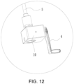
- FIG. 12 is an enlarged view of region F in FIG. 11 ;
- FIG. 13 is an enlarged view of region E in FIG. 11 .
- a louver awning with a hidden louver opening and closing driving structure comprises an awning frame assembly, a plurality of louvers 1 rotatably mounted on a top portion of the awning frame assembly, linkage bars 15 for linking the plurality of louvers 1 , and a louver opening and closing driving structure for driving the louvers 1 to open and close.
- the awning frame assembly comprises a plurality of columns 2 and ring beams 3 fitted together.
- the louver opening and closing driving structure comprises a hand-operated mechanism 4 fitted on one of the columns 2 , a transmission assembly transmissively coupled to the hand-operated mechanism 4 and a louver transmission mechanism transmissively coupled to the transmission assembly.
- the transmission assembly is used to transmit power input by the hand-operated mechanism 4 to the louver transmission mechanism, and the louver transmission mechanism is used to drive the louvers 1 to rotate so as to realize opening and closing of the louvers 1 .
- the louver transmission mechanism comprises a crank connecting rod mechanism.
- the crank connecting rod mechanism comprises a crank 6 and a connecting rod 7 rotatably coupled to the crank 6 .
- the crank 6 is used to be transmissively coupled to a second transmission assembly, and the connecting rod 7 is used to be rotatably coupled to the louver 1 .
- the crank 6 is capable of driving the louvers 1 to rotate through the connecting rod 7 , so as to realize the opening and closing of the louvers 1 .
- the transmission assembly comprises a first transmission mechanism 10 transmissively coupled to the hand-operated mechanism 4 , a first transmission rod 5 transmissively coupled to the first transmission mechanism 10 and vertically arranged, and a second transmission mechanism 11 transmissively coupled to an upper end of the first transmission rod 5 .
- the hand-operated mechanism 4 is used to drive the first transmission mechanism 11 to rotate
- the first transmission mechanism 11 is used to drive the first transmission rod 5 to rotate
- the first transmission rod 5 is used to drive the second transmission mechanism 11 to rotate
- the second transmission mechanism 11 is used to drive the louver transmission mechanism to rotate.
- the hand-operated mechanism 4 is a hand crank 4 , the rotation axis of the hand crank 4 is arranged horizontally, and the first transmission mechanism 10 has a bevel gear transmission structure or a worm gear transmission structure, preferably a bevel gear transmission structure.
- the lower end of the hand crank 4 and the lower end of the first transmission rod 5 are respectively fixed on two transmission shafts of the bevel gear transmission structure, and the bevel gear transmission structure works by operating the hand crank 4 .
- the bevel gear transmission structure is a publicly known technology in the field of machinery, its specific structure is shown in FIG. 2 , and will not be described.
- the bevel gear transmission structure or the worm gear transmission structure of the second transmission mechanism 11 is preferably a worm gear transmission structure.
- the upper end of the first transmission rod 5 is connected to the worm of the worm gear transmission structure, and the transmission shaft with a worm gear in the worm gear transmission structure is transmissively coupled to the crank 6 . Since the worm gear transmission structure is a publicly known technology in the field of machinery, it will not be described.
- the first transmission mechanism 10 , the first transmission rod 5 and the second transmission mechanism 11 are all fitted in the one of the columns 2 , and the second transmission mechanism 11 is specifically located at the upper end of the one of the columns 2 .
- each of the columns 2 is fitted to a first profile connector 8
- the end portion of each of the ring beams 3 is fitted to a second profile connector 9
- the first profile connector 8 has an L-shaped structure.
- the first profile connector 8 of the column 2 and the second profile connector 9 on two adjacent ring beams 3 are fastened and combined through a concave-convex structure and are fitted through fasteners, so as to realize quick and firm connection between the columns 2 and the ring beams 3 .
- first profile connector 8 is inserted into the upper end of each of the columns 2 , and each of the columns 2 is used to limit the first profile connector 8 in the horizontal direction, such that the first profile connector 8 is unmovable in the horizontal direction.
- each of the columns 2 is provided with a mounting opening 200 which is formed by openings on both sides of the column 2 corresponding to two adjacent ring beams 3 , thus facilitating the ring beams 3 to extend into the column 2 .
- the bottom portion of the mounting opening 200 is fitted to a support plate 201 , and two sides of the mounting opening 200 are provided with limiting blocks 202 .
- the first profile connector 8 is inserted into the mounting opening 200 , supported on the support plate 201 and limited by the limiting blocks 202 .
- a cover plate 203 for covering the first profile connector 8 , the second profile connector 9 and the mounting opening 200 is also fitted on each of the columns 2 .
- one end of the second profile connector 9 is a tubular structure, which is inserted into the end portion of the ring beam 3 and fitted to the ring beam 3 through bolts
- the other end of the second profile connector 9 is a plate-like structure, which extends from the end portion of the ring beam 3 and is fitted to the first profile connector 8 through bolts.
- the protruding and recess structure comprises a groove 800 provided on the first profile connector 8 and a protruding rib 900 provided on the second profile connector 9 , and the protruding rib 900 is fastened with the groove 800 .
- the protruding and recess can also be designed in other forms.
- the louver blades of the louvers 1 have a sunlight plate structure or a cloth structure, and the cloth structure is mainly nylon, canvas, rain-proof cloth and the like.
- the sunlight plate structure is mainly made of PC/PET/PMMA/PP material and ABS plus PC material.
- the hand-operated mechanism 4 is rotated, which drives the first transmission mechanism 10 to rotate, the first transmission mechanism 10 drives the first transmission rod 5 to rotate, the first transmission rod 5 drives the second transmission mechanism 11 to rotate, the second transmission mechanism drives the louver driving structure to rotate the louvers 1 , and the louvers 1 are opened and closed together through the linkage bars 15 .
- a louver awning with a hidden louver opening and closing driving structure comprises an awning frame assembly, a plurality of louvers 1 rotatably mounted on a top of the awning frame assembly, linkage bars 15 for linking the plurality of louvers 1 , and a louver opening and closing driving structure for driving the louvers 1 to open and close.
- the awning frame assembly comprises a plurality of columns 2 and ring beams 3 fitted together.
- the louver opening and closing driving structure comprises a hand-operated mechanism 4 fitted on one of the columns 2 , a transmission assembly transmissively coupled to the hand-operated mechanism 4 and a louver transmission mechanism transmissively coupled to the transmission assembly.
- the transmission assembly is used to transmit power input by the hand-operated mechanism 4 to the louver transmission mechanism, and the louver transmission mechanism is used to drive the louver 1 to rotate so as to realize opening and closing of the louver 1 .
- the louver transmission mechanism comprises a crank connecting rod mechanism.
- the crank connecting rod mechanism comprises a crank 6 and a connecting rod 7 rotatably coupled to the crank 6 .
- the crank 6 is used to be transmissively coupled to a second transmission assembly, and the connecting rod 7 is used to be rotatably coupled to the louver 1 .
- the crank 6 is capable of driving the louvers 1 to rotate through the connecting rod 7 , so as to realize the opening and closing of the louvers 1 .
- the transmission assembly comprises a first transmission mechanism 10 transmissively coupled to the hand-operated mechanism 4 , a first transmission rod 5 transmissively coupled to the first transmission mechanism 10 and vertically arranged, a third transmission mechanism 12 transmissively coupled to the first transmission rod 5 , a second transmission rod 13 transmissively coupled to the third transmission mechanism 12 and horizontally arranged, and a fourth transmission mechanism 14 transmissively coupled to the second transmission rod 13 .
- the hand-operated mechanism 4 is used to drive the first transmission mechanism 10 to rotate, the first transmission mechanism 10 is used to drive the first transmission rod 5 to rotate, the first transmission rod 5 is used to drive the third transmission mechanism 12 to rotate, the third transmission mechanism 12 is used to drive the second transmission rod 13 to rotate, the second transmission rod 13 is used to drive the fourth transmission mechanism 14 to rotate, and the fourth transmission mechanism 14 is used to drive the louver transmission mechanism to rotate.
- the hand-operated mechanism 4 is a hand crank 4 , the rotation axis of the hand crank 4 is horizontally arranged, and the first transmission mechanism 10 has a bevel gear transmission structure or a worm gear transmission structure, preferably a bevel gear transmission structure.
- the lower ends of the hand crank 4 and the first transmission rod 5 are respectively transmissively coupled to two transmission shafts, which have bevel gears, of the bevel gear transmission structure, and the bevel gear transmission structure works by operating the hand crank 4 .
- the bevel gear transmission structure is a publicly known technology in the field of machinery, its specific structure is shown in FIG. 2 , and will not be described.
- the third transmission mechanism 12 is a bevel gear transmission structure or a worm gear transmission structure, preferably a bevel gear transmission structure.
- the upper end of the first transmission rod 5 and the second transmission rod 13 are respectively transmissively coupled to two transmission shafts with bevel gears. Since the bevel gear transmission structure is a publicly known technology in the field of machinery, it will not be described.
- the fourth transmission mechanism 14 is a bevel gear transmission structure or a worm gear transmission structure, preferably a worm gear transmission structure.
- the second transmission rod 13 is connected to a worm of the worm gear transmission structure, and a transmission shaft with a worm gear in the worm gear transmission structure is transmissively coupled to the crank 6 . Since the worm gear transmission structure is a publicly known technology in the field of machinery, it will not be described.
- the hand-operated mechanism 4 is fitted on the side of the column 2 , the first transmission mechanism 10 and the first transmission rod 5 are fitted in the column 2 , the third transmission mechanism 12 is fitted at the joint between the column 2 and the ring beam 3 , and the second transmission rod 13 and the fourth transmission mechanism 14 are fitted in the ring beam 3 .
- the louver blades of the louver 1 have a sunlight plate structure or a cloth structure, and the cloth structure is mainly nylon, canvas, rain-proof cloth and the like.
- the sunlight plate structure is mainly made of PC/PET/PMMA/PP material and ABS plus PC material.
- the hand-operated mechanism 4 is rotated to drive the first transmission mechanism 10 to rotate, which drives the first transmission rod 5 to rotate, which drives the third transmission mechanism 12 to rotate, the third transmission rod 13 drives the fourth transmission mechanism 14 to rotate, and the fourth transmission mechanism 14 drives the louver transmission mechanism to rotate, which drives the louvers 1 to rotate through linkage bars 15 .
- the transmission assembly is a timing belt mechanism which is fitted in one of the columns 2 in this embodiment.
- One synchronous wheel is located at the lower end of the column 2 and is transmissively coupled to the hand-operated mechanism 4
- the other synchronous wheel is located at the upper end of the column 2 and is transmissively coupled to the louver transmission mechanism.
- the timing belt mechanism is driven to rotate by operating the hand-operated mechanism 4 , and the timing belt mechanism drives the louver driving structure to rotate, so as to realize the opening and closing of the louver 1 .
Landscapes
- Engineering & Computer Science (AREA)
- Architecture (AREA)
- Civil Engineering (AREA)
- Structural Engineering (AREA)
- Specific Sealing Or Ventilating Devices For Doors And Windows (AREA)
Applications Claiming Priority (3)
| Application Number | Priority Date | Filing Date | Title |
|---|---|---|---|
| CN202120723191.X | 2021-04-09 | ||
| CN202120723191.XU CN216043002U (zh) | 2021-04-09 | 2021-04-09 | 一种具有隐藏式百叶开合驱动结构的百叶篷 |
| PCT/CN2021/094272 WO2022213451A1 (zh) | 2021-04-09 | 2021-05-18 | 一种具有隐藏式百叶开合驱动结构的百叶篷 |
Publications (2)
| Publication Number | Publication Date |
|---|---|
| US20220372764A1 US20220372764A1 (en) | 2022-11-24 |
| US11834837B2 true US11834837B2 (en) | 2023-12-05 |
Family
ID=83283062
Family Applications (1)
| Application Number | Title | Priority Date | Filing Date |
|---|---|---|---|
| US17/425,732 Active 2041-12-24 US11834837B2 (en) | 2021-04-09 | 2021-05-18 | Louver awning with hidden louver opening and closing driving structure |
Country Status (2)
| Country | Link |
|---|---|
| US (1) | US11834837B2 (de) |
| DE (1) | DE212021000244U1 (de) |
Cited By (2)
| Publication number | Priority date | Publication date | Assignee | Title |
|---|---|---|---|---|
| US20220136253A1 (en) * | 2020-11-04 | 2022-05-05 | Qingdao Activa Shade Inc. | Retractable shade structures |
| US20230193631A1 (en) * | 2020-04-21 | 2023-06-22 | Renson Sunprotection-Screens | Terrace canopy |
Families Citing this family (1)
| Publication number | Priority date | Publication date | Assignee | Title |
|---|---|---|---|---|
| US20220115981A1 (en) * | 2020-10-08 | 2022-04-14 | The Regents Of The University Of Colorado, A Body Corporate | Systems and methods for conserving thermal and electrical energy usage in buildings and houses |
Citations (13)
| Publication number | Priority date | Publication date | Assignee | Title |
|---|---|---|---|---|
| US4527355A (en) * | 1983-02-24 | 1985-07-09 | Zeon Kasei Co., Ltd. | Opening and closing type louver device |
| US5733036A (en) * | 1996-10-03 | 1998-03-31 | Montgomery; Tommie Lee | Louvered light control |
| US20160177575A1 (en) * | 2014-12-20 | 2016-06-23 | Michael Ivic | Pergola Cover |
| US9422715B1 (en) * | 2012-05-01 | 2016-08-23 | C. Scott Selzer | Louvered roof apparatus and control system |
| CN205617895U (zh) * | 2016-05-21 | 2016-10-05 | 浙江永强集团股份有限公司 | 一种帐篷的百叶窗顶棚结构 |
| US20180127982A1 (en) * | 2015-05-28 | 2018-05-10 | Renson Sunprotection-Screens Nv | Screen device |
| CN208718489U (zh) * | 2018-06-12 | 2019-04-09 | 浙江永强集团股份有限公司 | 户外帐篷及其百叶旋转装置 |
| CN110043110A (zh) * | 2019-04-16 | 2019-07-23 | 广州格绿朗遮阳篷科技有限公司 | 一种百叶翻板遮阳篷 |
| CN111794457A (zh) | 2020-06-09 | 2020-10-20 | 浙江永强集团股份有限公司 | 一种具有中心驱动长百叶篷顶开合结构的帐篷 |
| US20210010270A1 (en) * | 2020-08-13 | 2021-01-14 | Zhejiang Linya Co.,Ltd | Multi-blade top awning capable of being opened/closed bidirectionally by 360 degrees |
| US10988936B2 (en) * | 2019-05-06 | 2021-04-27 | Johanes SOETANTO | Pergola louver tilt system |
| US10988926B2 (en) * | 2017-11-02 | 2021-04-27 | Panel Uk Ltd | Apparatus comprising a roof panel and control system for opening and closing the roof panel |
| US20210332587A1 (en) * | 2020-04-23 | 2021-10-28 | Rostyslav Geriavenko | Louvered pergola |
-
2021
- 2021-05-18 DE DE212021000244.7U patent/DE212021000244U1/de active Active
- 2021-05-18 US US17/425,732 patent/US11834837B2/en active Active
Patent Citations (14)
| Publication number | Priority date | Publication date | Assignee | Title |
|---|---|---|---|---|
| US4527355A (en) * | 1983-02-24 | 1985-07-09 | Zeon Kasei Co., Ltd. | Opening and closing type louver device |
| US5733036A (en) * | 1996-10-03 | 1998-03-31 | Montgomery; Tommie Lee | Louvered light control |
| US9422715B1 (en) * | 2012-05-01 | 2016-08-23 | C. Scott Selzer | Louvered roof apparatus and control system |
| US20160177575A1 (en) * | 2014-12-20 | 2016-06-23 | Michael Ivic | Pergola Cover |
| US20180127982A1 (en) * | 2015-05-28 | 2018-05-10 | Renson Sunprotection-Screens Nv | Screen device |
| CN205617895U (zh) * | 2016-05-21 | 2016-10-05 | 浙江永强集团股份有限公司 | 一种帐篷的百叶窗顶棚结构 |
| US10988926B2 (en) * | 2017-11-02 | 2021-04-27 | Panel Uk Ltd | Apparatus comprising a roof panel and control system for opening and closing the roof panel |
| CN208718489U (zh) * | 2018-06-12 | 2019-04-09 | 浙江永强集团股份有限公司 | 户外帐篷及其百叶旋转装置 |
| CN110043110A (zh) * | 2019-04-16 | 2019-07-23 | 广州格绿朗遮阳篷科技有限公司 | 一种百叶翻板遮阳篷 |
| US10988936B2 (en) * | 2019-05-06 | 2021-04-27 | Johanes SOETANTO | Pergola louver tilt system |
| US20210332587A1 (en) * | 2020-04-23 | 2021-10-28 | Rostyslav Geriavenko | Louvered pergola |
| CN111794457A (zh) | 2020-06-09 | 2020-10-20 | 浙江永强集团股份有限公司 | 一种具有中心驱动长百叶篷顶开合结构的帐篷 |
| US20210010270A1 (en) * | 2020-08-13 | 2021-01-14 | Zhejiang Linya Co.,Ltd | Multi-blade top awning capable of being opened/closed bidirectionally by 360 degrees |
| US11421422B2 (en) * | 2020-08-13 | 2022-08-23 | Zhejiang Linya Co., Ltd | Multi-blade top awning capable of being opened/closed bidirectionally by 360 degrees |
Cited By (2)
| Publication number | Priority date | Publication date | Assignee | Title |
|---|---|---|---|---|
| US20230193631A1 (en) * | 2020-04-21 | 2023-06-22 | Renson Sunprotection-Screens | Terrace canopy |
| US20220136253A1 (en) * | 2020-11-04 | 2022-05-05 | Qingdao Activa Shade Inc. | Retractable shade structures |
Also Published As
| Publication number | Publication date |
|---|---|
| DE212021000244U1 (de) | 2022-08-25 |
| US20220372764A1 (en) | 2022-11-24 |
Similar Documents
| Publication | Publication Date | Title |
|---|---|---|
| US11834837B2 (en) | Louver awning with hidden louver opening and closing driving structure | |
| EP3929373B1 (de) | Vordach mit einer mittig angetriebenen öffnungs- und schliessstruktur mit langen lüftungslamellen | |
| CN110886533B (zh) | 一种百叶篷 | |
| CN218522083U (zh) | 一种同步转动伸缩式百叶顶帐篷 | |
| CN220133305U (zh) | 一种全密封的翻板百叶结构 | |
| WO2022213451A1 (zh) | 一种具有隐藏式百叶开合驱动结构的百叶篷 | |
| US20230295932A1 (en) | Sunshade canopy | |
| CN110847469B (zh) | 一种平动式屋顶开合系统 | |
| CN218622612U (zh) | 一种厂房用大跨度钢结构 | |
| JP2004508008A (ja) | 温室用組立式パネル及びこれを用いた換気システム | |
| CN216197068U (zh) | 一种隐藏式百叶开合驱动结构 | |
| CN216713637U (zh) | 一种百叶篷 | |
| CN211448433U (zh) | 一种百叶篷用百叶片翻转联动机构 | |
| CN215520713U (zh) | 一种安装于户外的遮阳结构 | |
| CN2599920Y (zh) | 屋面可开启式连栋温室 | |
| CN215291020U (zh) | 百叶遮阳棚 | |
| CN215168653U (zh) | 一种百叶篷用梁柱安装结构 | |
| CN213038709U (zh) | 顶篷伸缩驱动机构和铰链伸缩遮阳篷 | |
| CN212836345U (zh) | 篷布铰链伸缩组件和铰链伸缩遮阳篷 | |
| CN116791937B (zh) | 一种户外百叶篷 | |
| CN220343001U (zh) | 一种方便折叠的农业大棚 | |
| CN219548692U (zh) | 一种平开窗用便捷开窗机构 | |
| CN2560707Y (zh) | 帐篷骨架 | |
| CN214482485U (zh) | 用于蔬菜早熟栽培的可调式翻转式盖棚结构 | |
| WO2023004989A1 (zh) | 一种遮阳篷用快装式侧边百叶隔断机构 |
Legal Events
| Date | Code | Title | Description |
|---|---|---|---|
| FEPP | Fee payment procedure |
Free format text: ENTITY STATUS SET TO UNDISCOUNTED (ORIGINAL EVENT CODE: BIG.); ENTITY STATUS OF PATENT OWNER: SMALL ENTITY |
|
| AS | Assignment |
Owner name: LINHAI MEIYANG PARASOL INDUSTRY CO.,LTD, CHINA Free format text: ASSIGNMENT OF ASSIGNORS INTEREST;ASSIGNORS:WANG, YINGYING;KE, YUEFU;ZHU, YI;REEL/FRAME:057011/0758 Effective date: 20210617 |
|
| FEPP | Fee payment procedure |
Free format text: ENTITY STATUS SET TO SMALL (ORIGINAL EVENT CODE: SMAL); ENTITY STATUS OF PATENT OWNER: SMALL ENTITY |
|
| STPP | Information on status: patent application and granting procedure in general |
Free format text: DOCKETED NEW CASE - READY FOR EXAMINATION |
|
| STPP | Information on status: patent application and granting procedure in general |
Free format text: NON FINAL ACTION MAILED |
|
| STPP | Information on status: patent application and granting procedure in general |
Free format text: NOTICE OF ALLOWANCE MAILED -- APPLICATION RECEIVED IN OFFICE OF PUBLICATIONS |
|
| STPP | Information on status: patent application and granting procedure in general |
Free format text: PUBLICATIONS -- ISSUE FEE PAYMENT RECEIVED |
|
| STPP | Information on status: patent application and granting procedure in general |
Free format text: PUBLICATIONS -- ISSUE FEE PAYMENT VERIFIED |
|
| STCF | Information on status: patent grant |
Free format text: PATENTED CASE |