US11819911B2 - Die-casting machine and operating method - Google Patents
Die-casting machine and operating method Download PDFInfo
- Publication number
- US11819911B2 US11819911B2 US17/352,935 US202117352935A US11819911B2 US 11819911 B2 US11819911 B2 US 11819911B2 US 202117352935 A US202117352935 A US 202117352935A US 11819911 B2 US11819911 B2 US 11819911B2
- Authority
- US
- United States
- Prior art keywords
- casting
- valve
- melt
- piston
- mould
- Prior art date
- Legal status (The legal status is an assumption and is not a legal conclusion. Google has not performed a legal analysis and makes no representation as to the accuracy of the status listed.)
- Active, expires
Links
- 238000004512 die casting Methods 0.000 title claims abstract description 53
- 238000011017 operating method Methods 0.000 title description 19
- 238000005266 casting Methods 0.000 claims abstract description 597
- 239000000155 melt Substances 0.000 claims abstract description 209
- 239000000289 melt material Substances 0.000 claims abstract description 110
- 238000000034 method Methods 0.000 claims description 42
- 230000000694 effects Effects 0.000 description 10
- 230000015572 biosynthetic process Effects 0.000 description 9
- 125000004122 cyclic group Chemical group 0.000 description 9
- 238000004904 shortening Methods 0.000 description 9
- 230000008901 benefit Effects 0.000 description 6
- 238000011161 development Methods 0.000 description 6
- 230000008569 process Effects 0.000 description 6
- 238000001816 cooling Methods 0.000 description 5
- 230000036316 preload Effects 0.000 description 5
- 230000009471 action Effects 0.000 description 4
- 230000001276 controlling effect Effects 0.000 description 4
- 238000003745 diagnosis Methods 0.000 description 4
- 238000010586 diagram Methods 0.000 description 4
- 238000006073 displacement reaction Methods 0.000 description 4
- 239000008186 active pharmaceutical agent Substances 0.000 description 3
- 238000005429 filling process Methods 0.000 description 3
- 239000011133 lead Substances 0.000 description 3
- 239000007788 liquid Substances 0.000 description 3
- 229910052751 metal Inorganic materials 0.000 description 3
- 239000002184 metal Substances 0.000 description 3
- 238000011144 upstream manufacturing Methods 0.000 description 3
- RYGMFSIKBFXOCR-UHFFFAOYSA-N Copper Chemical compound [Cu] RYGMFSIKBFXOCR-UHFFFAOYSA-N 0.000 description 2
- FYYHWMGAXLPEAU-UHFFFAOYSA-N Magnesium Chemical compound [Mg] FYYHWMGAXLPEAU-UHFFFAOYSA-N 0.000 description 2
- 229910000831 Steel Inorganic materials 0.000 description 2
- RTAQQCXQSZGOHL-UHFFFAOYSA-N Titanium Chemical compound [Ti] RTAQQCXQSZGOHL-UHFFFAOYSA-N 0.000 description 2
- HCHKCACWOHOZIP-UHFFFAOYSA-N Zinc Chemical compound [Zn] HCHKCACWOHOZIP-UHFFFAOYSA-N 0.000 description 2
- 230000004913 activation Effects 0.000 description 2
- 229910045601 alloy Inorganic materials 0.000 description 2
- 239000000956 alloy Substances 0.000 description 2
- 239000004411 aluminium Substances 0.000 description 2
- 229910052782 aluminium Inorganic materials 0.000 description 2
- XAGFODPZIPBFFR-UHFFFAOYSA-N aluminium Chemical compound [Al] XAGFODPZIPBFFR-UHFFFAOYSA-N 0.000 description 2
- 230000015556 catabolic process Effects 0.000 description 2
- 238000004891 communication Methods 0.000 description 2
- 229910052802 copper Inorganic materials 0.000 description 2
- 239000010949 copper Substances 0.000 description 2
- 238000006731 degradation reaction Methods 0.000 description 2
- 229910001338 liquidmetal Inorganic materials 0.000 description 2
- 239000011777 magnesium Substances 0.000 description 2
- 229910052749 magnesium Inorganic materials 0.000 description 2
- 238000012423 maintenance Methods 0.000 description 2
- 150000002739 metals Chemical class 0.000 description 2
- 238000012544 monitoring process Methods 0.000 description 2
- 230000001105 regulatory effect Effects 0.000 description 2
- 239000010959 steel Substances 0.000 description 2
- 230000002123 temporal effect Effects 0.000 description 2
- 239000010936 titanium Substances 0.000 description 2
- 229910052719 titanium Inorganic materials 0.000 description 2
- 230000001960 triggered effect Effects 0.000 description 2
- 239000011701 zinc Substances 0.000 description 2
- 229910052725 zinc Inorganic materials 0.000 description 2
- 210000000746 body region Anatomy 0.000 description 1
- 230000000052 comparative effect Effects 0.000 description 1
- 230000006835 compression Effects 0.000 description 1
- 238000007906 compression Methods 0.000 description 1
- 230000008878 coupling Effects 0.000 description 1
- 238000010168 coupling process Methods 0.000 description 1
- 238000005859 coupling reaction Methods 0.000 description 1
- 230000001419 dependent effect Effects 0.000 description 1
- 238000013461 design Methods 0.000 description 1
- 238000011156 evaluation Methods 0.000 description 1
- 230000002349 favourable effect Effects 0.000 description 1
- 239000011796 hollow space material Substances 0.000 description 1
- 239000011344 liquid material Substances 0.000 description 1
- 230000007257 malfunction Effects 0.000 description 1
- 238000000465 moulding Methods 0.000 description 1
- 230000002028 premature Effects 0.000 description 1
- 230000002265 prevention Effects 0.000 description 1
- 230000000630 rising effect Effects 0.000 description 1
- 238000007711 solidification Methods 0.000 description 1
- 230000008023 solidification Effects 0.000 description 1
- 238000005507 spraying Methods 0.000 description 1
- 230000007704 transition Effects 0.000 description 1
Images


Classifications
-
- B—PERFORMING OPERATIONS; TRANSPORTING
- B22—CASTING; POWDER METALLURGY
- B22D—CASTING OF METALS; CASTING OF OTHER SUBSTANCES BY THE SAME PROCESSES OR DEVICES
- B22D17/00—Pressure die casting or injection die casting, i.e. casting in which the metal is forced into a mould under high pressure
-
- B—PERFORMING OPERATIONS; TRANSPORTING
- B22—CASTING; POWDER METALLURGY
- B22D—CASTING OF METALS; CASTING OF OTHER SUBSTANCES BY THE SAME PROCESSES OR DEVICES
- B22D17/00—Pressure die casting or injection die casting, i.e. casting in which the metal is forced into a mould under high pressure
- B22D17/20—Accessories: Details
- B22D17/32—Controlling equipment
-
- B—PERFORMING OPERATIONS; TRANSPORTING
- B22—CASTING; POWDER METALLURGY
- B22D—CASTING OF METALS; CASTING OF OTHER SUBSTANCES BY THE SAME PROCESSES OR DEVICES
- B22D18/00—Pressure casting; Vacuum casting
- B22D18/04—Low pressure casting, i.e. making use of pressures up to a few bars to fill the mould
-
- B—PERFORMING OPERATIONS; TRANSPORTING
- B22—CASTING; POWDER METALLURGY
- B22D—CASTING OF METALS; CASTING OF OTHER SUBSTANCES BY THE SAME PROCESSES OR DEVICES
- B22D17/00—Pressure die casting or injection die casting, i.e. casting in which the metal is forced into a mould under high pressure
- B22D17/02—Hot chamber machines, i.e. with heated press chamber in which metal is melted
- B22D17/04—Plunger machines
-
- B—PERFORMING OPERATIONS; TRANSPORTING
- B22—CASTING; POWDER METALLURGY
- B22D—CASTING OF METALS; CASTING OF OTHER SUBSTANCES BY THE SAME PROCESSES OR DEVICES
- B22D17/00—Pressure die casting or injection die casting, i.e. casting in which the metal is forced into a mould under high pressure
- B22D17/08—Cold chamber machines, i.e. with unheated press chamber into which molten metal is ladled
- B22D17/12—Cold chamber machines, i.e. with unheated press chamber into which molten metal is ladled with vertical press motion
-
- B—PERFORMING OPERATIONS; TRANSPORTING
- B22—CASTING; POWDER METALLURGY
- B22D—CASTING OF METALS; CASTING OF OTHER SUBSTANCES BY THE SAME PROCESSES OR DEVICES
- B22D17/00—Pressure die casting or injection die casting, i.e. casting in which the metal is forced into a mould under high pressure
- B22D17/20—Accessories: Details
- B22D17/2015—Means for forcing the molten metal into the die
- B22D17/203—Injection pistons
-
- B—PERFORMING OPERATIONS; TRANSPORTING
- B22—CASTING; POWDER METALLURGY
- B22D—CASTING OF METALS; CASTING OF OTHER SUBSTANCES BY THE SAME PROCESSES OR DEVICES
- B22D17/00—Pressure die casting or injection die casting, i.e. casting in which the metal is forced into a mould under high pressure
- B22D17/20—Accessories: Details
- B22D17/2015—Means for forcing the molten metal into the die
- B22D17/2053—Means for forcing the molten metal into the die using two or more cooperating injection pistons
-
- B—PERFORMING OPERATIONS; TRANSPORTING
- B22—CASTING; POWDER METALLURGY
- B22D—CASTING OF METALS; CASTING OF OTHER SUBSTANCES BY THE SAME PROCESSES OR DEVICES
- B22D17/00—Pressure die casting or injection die casting, i.e. casting in which the metal is forced into a mould under high pressure
- B22D17/20—Accessories: Details
- B22D17/2015—Means for forcing the molten metal into the die
- B22D17/2069—Exerting after-pressure on the moulding material
-
- B—PERFORMING OPERATIONS; TRANSPORTING
- B22—CASTING; POWDER METALLURGY
- B22D—CASTING OF METALS; CASTING OF OTHER SUBSTANCES BY THE SAME PROCESSES OR DEVICES
- B22D17/00—Pressure die casting or injection die casting, i.e. casting in which the metal is forced into a mould under high pressure
- B22D17/20—Accessories: Details
- B22D17/2084—Manipulating or transferring devices for evacuating cast pieces
-
- B—PERFORMING OPERATIONS; TRANSPORTING
- B22—CASTING; POWDER METALLURGY
- B22D—CASTING OF METALS; CASTING OF OTHER SUBSTANCES BY THE SAME PROCESSES OR DEVICES
- B22D18/00—Pressure casting; Vacuum casting
- B22D18/08—Controlling, supervising, e.g. for safety reasons
-
- B—PERFORMING OPERATIONS; TRANSPORTING
- B22—CASTING; POWDER METALLURGY
- B22D—CASTING OF METALS; CASTING OF OTHER SUBSTANCES BY THE SAME PROCESSES OR DEVICES
- B22D39/00—Equipment for supplying molten metal in rations
- B22D39/06—Equipment for supplying molten metal in rations having means for controlling the amount of molten metal by controlling the pressure above the molten metal
Definitions
- the invention relates to a die-casting machine having a casting mould, a casting chamber, a casting piston arranged in an axially movable manner in the casting chamber, a melt inlet channel which leads into the casting chamber, a shut-off valve in the melt inlet channel, a melt outlet channel which leads from the casting chamber to the casting mould, and a control unit for controlling the casting piston.
- the invention also relates to a method for operating such a die-casting machine, in which method, for carrying out a respective casting process, in a mould-filling phase, with the shut-off valve closed, the casting piston in the casting chamber is advanced from a casting start position to a filling end position and, as a result, melt material is pressed into the casting mould via the melt outlet channel and, in a subsequent refilling phase, the casting piston is moved back into the casting start position and, as a result, with the shut-off valve open, melt material is fed back to the casting chamber via the melt inlet channel.
- Die-casting machines of this type of the generic type and of similar types and associated operating methods are generally used for casting a specific component, also referred to as cast part, in the respective casting process or casting cycle.
- the present die-casting machine also referred to in short as machine below, and the present operating method are suitable in particular for metal die-casting, e.g. for casting liquid or partially liquid metal melts, such as zinc, lead, aluminium, magnesium, titanium, steel, copper, and alloys of these metals.
- the die-casting machine may be in particular a hot-chamber die-casting machine.
- the casting chamber is formed in a casting container which is immersed in a melt bath kept ready by a melt container.
- the casting mould usually contains a fixed and a moveable mould half, which between them form the mould cavity, also referred to as mould hollow space or, in a manner synonymous with this casting mould which is formed, mould for short.
- the melt outlet channel comprises a riser-tube region of a casting container, which contains the casting chamber, on the inlet side and a mouthpiece body, which is attached to the casting container, on the outlet side, i.e. after it leaves the casting chamber, the melt material arrives at a melt inlet in the region directly in front of the mould cavity, in which what is known as a gating cone is typically located, via the riser-tube region and the mouthpiece body.
- the casting piston In the refilling phase, the casting piston is moved back again from its filling end position to its initial position, i.e. casting start position, and the return movement of the casting piston refills the casting chamber with melt material via the melt inlet channel.
- the refilling phase can therefore also be referred to as the piston return phase.
- melt outlet channel leads out of the casting chamber separately from the melt inlet channel, i.e. melt inlet channel and melt outlet channel form two separate guide channels for the melt material with a casting-chamber inlet, at which the melt inlet channel opens out into the casting chamber, and a separate casting-chamber outlet, at which the melt outlet channel opens out of the casting chamber.
- melt inlet channel and melt outlet channel form two separate guide channels for the melt material with a casting-chamber inlet, at which the melt inlet channel opens out into the casting chamber, and a separate casting-chamber outlet, at which the melt outlet channel opens out of the casting chamber.
- shut-off valve a non-return valve which is actuated purely by melt pressure or an actively activatable shut-off valve.
- the latter is referred to in the present case as shut-off control valve and is controlled by the control unit.
- the shut-off control valve is usually kept closed during the entire mould-filling phase and kept open during the entire refilling phase.
- an actively controllable or activatable shut-off valve it offers the option of influencing or regulating the melt throughflow in the melt inlet channel as required, this also independently of the melt pressure ratios in the casting chamber and/or in the melt inlet channel.
- the control unit comprises a single control device in which all control functionalities of the die-casting machine are integrated, or a plurality of single control devices, each of which controls and/or regulates specific machine components and which preferably have a communication link with one another.
- the control unit may be configured at least partially in hardware and/or at least partially as software.
- the control unit controls in particular the casting piston, more precisely the movement thereof, and optionally one or more further machine components, such as in particular the shut-off control valve, if the shut-off valve is implemented by such a shut-off control valve.
- the patent publication EP 0 576 406 B1 discloses such a procedure for a system which has a casting piston of the displacement type, as is known as an alternative to a casting piston of the spool type, and has a shut-off control valve arranged directly at an opening of the melt inlet channel into the casting chamber.
- the outer dimension of the casting piston corresponds to the inner dimension of the casting chamber, the piston being sealed with respect to the casting chamber wall. Consequently, in this case, when it advances the casting piston pushes the melt material in the casting chamber completely forward and in the process exerts the pressure on the melt material required to press it into the mould cavity.
- the outer dimension of the casting piston is suitably smaller than the inner dimension of the casting chamber, and therefore the casting piston dips into the melt material of the casting chamber when it advances.
- the action of pressure on the melt material is brought about in this case by the displacement effect of the volume of the casting piston that dips into the melt material.
- the laid-open publication DE 32 48 423 A1 likewise discloses a die-casting machine of the generic type and an associated operating method, in said document a casting piston with a forward piston of the displacement type and a pressurized gas which additionally can be fed to the casting chamber being used and the shut-off control valve being located in a casting container, containing the casting chamber, at a respective distance in terms of flow upstream of the casting chamber and downstream of an inlet into the casting container in the melt inlet channel. During the mould-filling phase, the shut-off control valve is kept closed.
- the shut-off control valve is opened and conducts a certain amount of pressurized gas into the casting chamber, in order, before the shut-off control valve is opened, to avoid the formation of a vacuum in the casting chamber and to avoid the spraying of melt which has been pulled in as a result onto the casting-piston part to the rear of the forward piston and to bias the gas pressure in the casting chamber by a certain amount above atmospheric pressure.
- the shut-off control valve is closed again.
- a cycle time i.e. duration of a respective casting process, which is as short as possible is sought and for reasons relating to the quality of the cast part an air fraction in the cast part which is as low as possible, i.e. a minimum air porosity of the cast part, is sought.
- the patent publication EP 1 284 168 B1 proposes, at the beginning of the mould-filling phase and/or before the actual mould-filling phase, in a pre-filling phase to advance the casting piston already when the mould is still open far enough that the melt material fills the riser-channel region and the mouthpiece body region, before then the mould is closed and the casting piston is advanced again to carry out the actual mould-filling phase.
- the casting piston is of the spool type and itself functions as a shut-off member in that it opens up the casting chamber inlet by performing a return movement behind it during the refilling phase and shuts off said casting chamber inlet by advancing beyond it during the mould-filling phase.
- the invention is based on the technical problem of providing a die-casting machine and an associated operating method of the type mentioned at the outset, which offer advantages over the abovementioned prior art in particular in terms of achieving relatively short casting cycle times and/or a relatively low air porosity in the cast part and/or in terms of a relatively low tendency to wear of casting piston and casting chamber and/or avoiding the formation of a melt droplet in the gating-cone region.
- the invention solves this problem by providing a die-casting machine operating method and a die-casting machine in accordance with the independent claims.
- Advantageous refinements of the invention are specified in the dependent claims.
- the casting piston in the casting chamber is advanced from a casting start position to a filling end position and, as a result, melt material is pressed into the casting mould via the melt outlet channel and, in a subsequent refilling phase, the casting piston is moved back into the casting start position and, as a result, with the shut-off valve open, melt material is fed back to the casting chamber via the melt inlet channel
- the previously open shut-off valve in the refilling phase of the casting process, is closed before the casting piston has reached its casting start position by virtue of its return movement, and as a result of the further return movement of the casting piston melt material in the melt outlet channel is back-suctioned, i.e. is back-suctioned from the melt outlet channel partially into the casting chamber.
- the closing of the shut-off valve may be performed actively by the control unit in the case of a shut-off control valve and e.g. by a preload element which preloads the valve in its closed position, such as a preload spring, in the case of a non-return valve.
- shut-off valve in an initial stage of the refilling phase the shut-off valve is initially opened when the casting piston moves back, with the result that the casting chamber is refilled with melt material via the melt inlet channel, while in the remaining stage of the refilling phase the shut-off valve is closed, with the result that the further movement back of the casting piston makes it possible to back-suction melt material in the melt outlet channel.
- the shut-off valve when implemented as a shut-off control valve the shut-off valve is controlled into its open position by the assigned control unit, and when implemented as a non-return valve the shut-off valve is controlled by the melt negative pressure in the casting chamber.
- This procedure according to the invention advantageously combines the required refilling of the casting chamber with melt material via the melt inlet channel with a partial back-suctioning of melt material in the melt outlet channel.
- the non-solidified melt material in the melt outlet channel is preferably not completely back-suctioned to a melt fill level which is present in the casting chamber or an upstream melt bath, but rather may remain in the melt outlet channel up to a front region thereof to an extent which can be set and/or predefined by correspondingly selecting the point in time at which the shut-off valve is closed and/or the associated position of the casting piston, and therefore in a subsequent casting process does not first have to be advanced to this fill level in the melt outlet channel.
- This procedure according to the invention offers a number of advantages on account of these properties.
- the cycle time for the casting processes which follow one another can be shortened.
- the movement stroke of the casting piston in the casting chamber can be reduced, as a result of which associated wear effects can be minimized.
- the wear at wear-afflicted parts of the casting chamber and the casting piston, including customary piston rings, is also thus considerably reduced by this procedure according to the invention, e.g. in comparison with conventional systems in which the casting piston functions as a shut-off member for the melt inlet channel, because the negative pressure which occurs during the return movement of the casting piston in the casting chamber can be kept distinctly lower, if needed, by suitably controlling and/or switching over the shut-off valve.
- melt outlet channel can remain predominantly filled with melt material between casting processes which follow one another, at the beginning of the respective casting process air is present in the front portion of the melt outlet channel to a correspondingly small extent, as a result of which the air porosity of the cast part produced can be significantly reduced, which accordingly can considerably improve the quality of the cast part produced.
- the back-suctioning of non-solidified melt material in the melt outlet channel makes it possible to a controllable and/or monitored extent, i.e. in a controllable and/or predefinable amount, to very advantageously prevent an undesired formation of a melt droplet in the region of the gating cone of the die-casting machine and/or the moulding tool thereof, i.e. at the sprue or at the transition or exit of the melt outlet channel or of a mouthpiece body, forming the outlet-side portion of said melt outlet channel, to a subsequent mouthpiece nozzle or mouthpiece tip, by back-suctioning the melt material away from the outlet region there of the melt outlet channel to a greater or lesser extent into the melt outlet channel.
- the extent of back-suctioning may be suitably set or predefined, i.e. selected, depending on requirements and the conditions of the die-casting machine, expediently in such a way that on the one hand said formation of a melt droplet is reliably prevented and on the other hand the melt material still remains relatively far in front, i.e. preferably in a front region or region which lies far in front, in the melt outlet channel.
- the melt material is back-suctioned far enough that it on the one hand remains, i.e. is available, in the melt outlet channel as far as a front region, or region which lies relatively far in front, of said melt outlet channel, but on the other hand is located behind the melt outlet channel at a certain, relatively low distance of e.g. approx.
- the back-suctioning stroke of the casting piston required for this purpose from the position of the casting piston at which the shut-off valve is closed to the casting start position is in the range of one millimeter to a few millimeters, e.g. between approx. 2 mm and 20 mm.
- the back-suctioning moreover has the advantage that a travel of the stroke of the casting piston that in a first stage of the mould-filling phase can be used in the subsequent casting process to accelerate the casting piston before the casting piston begins to press the melt material into the mould is correspondingly obtained as a result.
- This can be favourable primarily also in the case of moulds with no sprue or only a relatively small sprue.
- a further advantage of the back-suctioning may result in the case of applications in which the gate to the cast part solidifies before the still partially liquid material in the runner. In that case, it is possible to back-suction melt material which has not yet solidified from the gating cone, with the result that said melt material does not have to be melted again. Depending on the casting mould and the other conditions, this may be a melt material proportion of e.g. up to approx. 5% with respect to the amount of melt introduced into the casting mould.
- the casting piston in the refilling phase the casting piston is moved back in the period of time when the shut-off valve is closed at a lower speed than in the preceding period of time when the shut-off valve is still open.
- the casting piston is moved back during the final back-suctioning stage when the shut-off valve is closed at a lower speed than in the initial refilling stage when the shut-off valve is open.
- the previously open shut-off valve is closed as soon as the casting piston has reached a valve switchover position by virtue of its return movement.
- this may be performed by way of an actively controlled valve switchover at this point in time, and in the case of a non-return valve may be performed e.g. in that the casting piston is stopped in the valve switchover position and/or the closed casting mould is opened, and therefore no further melt negative pressure is created in the casting chamber, as a result of which the non-return valve moves in an automatically resetting manner into its closed position.
- shut-off valve causes the shut-off valve to switch over from its open position to its closed position in dependence on the position of the casting piston, more precisely in dependence on it reaching a particular position, in the present case referred to as valve switchover position or else valve reversal position.
- the closing of the shut-off valve ends the feed of melt material into the casting chamber via the melt inlet channel, and therefore melt material can be back-suctioned from the melt outlet channel into the casting chamber to the desired extent by the further return movement of the casting piston from its valve switchover position to reaching its casting start position.
- undesired opening of the shut-off valve during this time period can be prevented e.g.
- the activation for reversing the shut-off valve from its open position into its closed position during the refilling phase of the casting process is triggered in a different way, e.g. by virtue of the elapsing of a time period, predefinable for this, since the beginning of the refilling phase or since the beginning of the return movement of the casting piston.
- a stroke distance between the valve switchover position of the casting piston and the casting start position can be variably predefined. This measure makes it possible to react flexibly to different system conditions.
- the stroke distance between the valve switchover position of the casting piston and the casting start position determines the proportion of the final return movement of the casting piston from its valve switchover position to its casting start position with respect to the entire casting piston stroke, which is given by the distance between the filling end position and the casting start position, and thus also the extent of melt back-suctioning in the melt outlet channel.
- This stroke distance is naturally greater than zero and smaller than the entire casting piston stroke, i.e.
- the stroke distance between the filling end position and the casting start position can be set to a respectively desired value or value corresponding to the requirements of the respective usage situation, e.g. to a value between approx. 2 mm and 20 mm and more specifically between approx. 4 mm and 8 mm, depending on requirements and the system conditions of the die-casting machine, said value in corresponding implementations being at most half or at most a third or at most a quarter of the entire casting piston stroke, or even less.
- the extent of back-suctioning of melt material in the melt outlet channel increases as the stroke distance between the valve switchover position and the casting start position increases; the selection of a shorter stroke distance reduces the amount of melt material back-suctioned in the melt outlet channel.
- the stroke distance between the valve switchover position and the casting start position of the casting piston may be selected differently e.g. for different casting moulds used exchangeably in the die-casting machine. In alternative embodiments, this stroke distance can be predefined in an invariable manner, if a variable adjustment is not required.
- the casting piston in the refilling phase of the casting process, the casting piston is held in the valve switchover position during a halt period before it is moved back again to its casting start position.
- the halt period for the return movement of the casting piston may be used to switch over the shut-off valve from its open position into its closed position and, as required, to open the casting mould.
- the shut-off valve can be switched over during a period of time in which there is no moved melt flow in the melt inlet channel and thus through the shut-off valve, but rather the melt material is stationary in the melt inlet channel.
- the halt period may be set suitably in terms of its temporal duration, e.g.
- the shut-off valve is switched over from its open position into its closed position without interrupting the return movement of the casting piston, i.e. without the casting piston being completely stopped in its return movement after reaching its valve switchover position.
- the casting mould in the refilling phase of the casting process, is kept closed for at least as long as the shut-off valve is still open.
- This measure has the result that the casting chamber is refilled with melt material via the melt inlet channel by virtue of the return movement of the casting piston, but no appreciable back-suctioning of melt material in the melt outlet channel takes place yet provided the shut-off valve is in its open position.
- the casting mould since the casting mould is still closed and contains the cast part, which is generally at this point in time already at least partially solidified, no appreciable amount of air can pass into the melt outlet channel via said casting mould, and therefore, in this initial stage of the refilling phase, no melt material is back-suctioned from the melt outlet channel into the casting chamber yet.
- the casting mould is already open and/or the opening thereof has commenced in any case while the shut-off valve is still open.
- shut-off control valve in the refilling phase of the casting process, opening of the casting mould is commenced after the casting piston has reached its casting start position. This procedure brings about the back-suctioning of melt material in the melt outlet channel essentially not until the casting piston has reached its casting start position.
- the casting piston As a result of the return movement of the casting piston from the valve switchover position, in which, when it is reached, the shut-off control valve is closed, into the casting start position, the casting piston first builds up a corresponding negative pressure, and after the opening of the casting mould commences, the melt material is then back-suctioned from the melt outlet channel into the casting chamber to a corresponding extent by the associated negative-pressure effect.
- opening of the casting mould is commenced after the casting piston has reached its valve switchover position and before it has reached its casting start position.
- melt material can be back-suctioned in the melt outlet channel or from the melt outlet channel into the casting chamber already during the further return movement of the casting piston into its casting start position.
- the opening of the casting mould can be commenced at any desired point in time during the return movement of the casting piston from its valve switchover position into its casting start position, and in corresponding implementations further alternatively also already before the casting piston has reached its valve switchover position and the shut-off valve is closed.
- the casting piston in the refilling phase of the casting process, the casting piston is stopped in its valve switchover position and is advanced from its valve switchover position into its casting start position as soon as the casting mould has reached a particular casting-piston-triggering mould opening position when it is opened.
- the further return movement of the casting piston after being stopped in its valve switchover position is matched to the opening process of the casting mould, specifically in such a way that the casting piston is not advanced to its casting start position until the casting mould has opened by a predefinable extent defined by the set casting-piston-triggering mould opening position.
- the process of back-suctioning melt material in the melt outlet channel in the last stage of the refilling phase of the casting process can be further optimized.
- the return movement of the casting piston takes place without taking into account the current opening position of the casting mould, provided that there is no application-related requirement for this.
- the casting piston is advanced from its casting start position, reached during the refilling phase of a respectively previous casting process, to a pre-filling position during an initial pre-filling stage of the mould-filling phase of a subsequent casting process with the casting mould being not yet completely closed, and only thereafter is the casting mould completely closed and the casting piston advanced further from this pre-filling position to its filling end position.
- the casting piston in the casting chamber is advanced from a start-of-operation position into a given pre-filling position, and then moved back into its casting start position when the shut-off valve is open.
- the casting mould can be closed already before or at the start of this pre-filling phase or as an alternative can be kept open still during the advancement of the casting piston in this pre-filling phase and closed only before the return movement of the casting piston or when the shut-off valve opens.
- the casting mould can be closed already before or at the start of this pre-filling phase or as an alternative can be kept open still during the advancement of the casting piston in this pre-filling phase and closed only before the return movement of the casting piston or when the shut-off valve opens.
- This procedure according to the invention constitutes a specific start-of-operation measure which can be used advantageously when a cyclic casting operation of the die-casting machine for the cyclic casting of a plurality of identical cast parts by means of a specific casting mould in casting processes or casting cycles which follow one another is commenced, e.g. after assembly of the casting mould or the casting tool on the die-casting machine or after a restart of the die-casting machine with a specific assembled casting mould.
- the start-of-operation casting process constitutes a first casting process or casting cycle for producing the desired cast part after a start of operation of the machine.
- the melt material is not yet located in a front region of the melt outlet channel but rather at most in a rear region of the melt outlet channel, e.g. up to the height of a melt fill level in the casting chamber or a melt bath in which a casting container containing the casting chamber is immersed.
- the specific start-of-operation casting process ensures that the melt material is present in a front region of the melt outlet channel also already for the first of many casting processes which follow one another after such a start of operation of the machine when the mould-filling phase is commenced, in that the casting piston is advanced out of its casting start position in the direction of its filling end position, in order to press the melt material into the casting mould.
- the casting piston is advanced from its start-of-operation position, in which it is situated at this point in time, initially only into the pre-filling position, the shut-off valve remaining closed, with the result that melt material from the casting chamber can be pressed into the melt outlet channel.
- the pre-filling position of the casting piston is determined by the fact that, when it is reached, the melt material has filled the melt outlet channel to a desired, predefinable extent.
- the subsequent opening of the shut-off valve and the return movement of the casting piston from its pre-filling position into its casting start position refills the casting chamber again with melt material via the melt inlet channel to a maximum extent in an amount which was pressed previously from the casting chamber into the melt outlet channel.
- melt material in the melt outlet channel is already available for this first casting process already up to a front region thereof, e.g. in the entire volume of a riser-channel portion and in the volume of an adjoining mouthpiece body portion of the melt outlet channel up to the front end region of the mouthpiece body and thus also significantly above the bath level of an assigned melt bath from which the melt material is fed to the casting chamber.
- the die-casting machine comprises a casting mould, a casting chamber, a casting piston arranged in an axially movable manner in the casting chamber, a melt inlet channel which leads into the casting chamber, a shut-off valve in the melt inlet channel, a melt outlet channel which leads from the casting chamber to the casting mould, and a control unit for controlling the casting piston.
- control unit and the shut-off valve are configured to bring the shut-off valve into a closed position and to control the casting piston in the casting chamber to advance from a casting start position to a filling end position, in order to press melt material into the casting mould via the melt outlet channel, and in a subsequent refilling phase firstly to bring the shut-off valve into an open position and to control the casting piston to move back to the casting start position, in order to feed melt material to the casting chamber via the melt inlet channel.
- the control unit and the shut-off valve are further configured to bring the shut-off valve into its closed position again still during the refilling phase, before the casting piston has reached its casting start position by virtue of its return movement, and to control the casting piston to back-suction melt material in the melt outlet channel by virtue of the further return movement of the casting piston, and/or during a start-of-operation casting process to control the casting piston to advance in the casting chamber from a start-of-operation position to a pre-filling position during a pre-filling phase of the start-of-operation casting process before the mould-filling phase with the shut-off valve closed, and then to bring the shut-off valve into its open position and to control the casting piston to move back to its casting start position.
- this die-casting machine is suitable in particular for carrying out the aspects mentioned of the operating method according to the invention.
- the shut-off valve is in the form of a shut-off control valve
- the control unit is configured to control the shut-off control valve. This allows active control of the shut-off valve by means of the control unit, in particular in order to bring it into its respectively desired open or closed position in the course of a casting process.
- the die-casting machine contains a valve actuator, activated by the control unit, for actuating the shut-off control valve.
- the actuator functions as a linking element between the control unit and the shut-off valve and may be suitably selected depending on the type of the control unit and the shut-off valve, e.g. of an electrical, magnetic, hydraulic, pneumatic or mechanical type.
- the valve actuation functionality may be integrated e.g. directly in the control unit.
- the shut-off valve is in the form of a non-return valve which is preloaded in its closed position.
- the shut-off valve is controlled or actuated in dependence on the pressure of the melt material acting on it, in particular on the melt pressure in the casting chamber.
- the die-casting machine contains a valve sensor unit for sensing one or more measured variables of the shut-off valve. This can be used e.g. to give feedback about the current position of the shut-off valve to the control unit by way of the valve sensor unit and/or to provide valve diagnosis information which provides information as to whether the shut-off valve operates in an error-free manner and/or in which state of use it is located and whether it requires e.g. maintenance.
- FIG. 1 shows a schematic longitudinal sectional view of a part, of interest in the present case, of a die-casting machine having a shut-off control valve as shut-off valve;
- FIG. 2 shows a flow diagram for illustrating an operating method for the die-casting machine from FIG. 1 from a start of operation
- FIG. 3 shows the view from FIG. 1 during operation of the machine according to the method from FIG. 2 at the beginning of a mould-filling phase of a first casting cycle
- FIG. 4 shows the view from FIG. 3 during the mould-filling phase
- FIG. 5 shows the view from FIG. 3 after the mould-filling phase has ended and at the beginning of a refilling phase of the first casting cycle
- FIG. 6 shows the view from FIG. 3 during the refilling phase
- FIG. 7 shows the view from FIG. 3 after the refilling of the casting chamber with melt has ended
- FIG. 8 shows the view from FIG. 3 during a melt back-suctioning operation which follows the melt refilling operation
- FIG. 9 shows the view from FIG. 3 towards the end of the first casting cycle
- FIG. 10 shows the view from FIG. 3 at the end of the mould-filling phase of a second casting cycle
- FIG. 11 shows a flow diagram for illustrating an operating method for the die-casting machine from FIG. 1 in a variant with an initial pre-filling phase after the start of operation;
- FIG. 12 shows the view from FIG. 3 during operation of the machine according to the method from FIG. 11 at the beginning of the initial pre-filling phase
- FIG. 13 shows the view from FIG. 12 at a later point in time of the initial pre-filling phase with refilling of the casting chamber with the melt;
- FIG. 14 shows the view from FIG. 12 at the end of a mould-filling phase, following the initial pre-filling phase, of the first casting cycle in the method variant from FIG. 11 ;
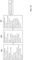
- FIG. 15 shows a flow diagram for illustrating an operating method for the die-casting machine from FIG. 1 in a variant with cyclic pre-filling before the mould-filling phase of a respective casting cycle;
- FIG. 16 shows the view from FIG. 1 for a variant of the die-casting machine having a non-return valve as shut-off valve.
- FIGS. 2 , 11 and 15 illustrate various advantageous variants of the inventive method for operating the die-casting machine in a flow diagram.
- FIGS. 1 , 3 to 10 and 12 to 14 and FIG. 16 schematically show the part of interest here of a die-casting machine in two implementations according to the invention, which may be operated by way of the method according to the invention.
- This die-casting machine may be in particular one of the hot-chamber type for die casting liquid or partially liquid metal melts, such as zinc, lead, aluminium, magnesium, titanium, steel, copper, and alloys of these metals.
- the die-casting machine comprises in particular a casting mould 1 which has a fixed mould half 1 a and a movable mould half 1 b , a casting chamber 2 , a casting piston 3 arranged in an axially moveable manner in the casting chamber 2 , a melt inlet channel 4 which leads into the casting chamber 2 , a shut-off valve 5 in the melt inlet channel 4 , a melt outlet channel 6 which leads from the casting chamber 2 to the casting mould 1 , and a control unit 7 .
- the shut-off valve 5 is configured as a shut-off control valve 5 S , i.e. as an activatable shut-off valve, which is activated by the control unit 7 directly or, as in the example shown, by way of an optional valve actuator 16 .
- the valve actuator 16 may be any desired actuator of the conventional type, as is known to a person skilled in the art for actuating such a valve per se. In this respect, depending on requirements and the usage situation, the actuator 16 may be in particular of a conventional electrically operating, hydraulically operating, pneumatically operating or mechanically directly operating actuator type, or an actuator type which operates mechanically by way of a lever system etc.
- the valve actuator 16 may be an actuator type which operates in a purely binary manner and switches over the shut-off valve 5 only between a first, open position and a second, closed position, or alternatively a proportional actuator type, which can open the shut-off valve 5 continually or in multiple stages, i.e. can also bring the shut-off valve 5 into one or more partial opening positions between its completely open position and its completely closed position and keep it there.
- the valve actuator may comprise e.g. variably settable end stops, which can be adjusted manually or automatically.
- FIG. 16 shows a variant of the die-casting machine which differs from that in FIG. 1 in that the shut-off valve 5 is configured as a non-return valve 5 R .
- control unit 7 is understood to mean encompassing all control elements of the die-casting machine for controlling and/or regulating the various components of the machine, for which purpose the control unit 7 , depending on the system configuration, may contain a single control device in which all control functionalities are integrated, or a plurality of individual control devices, each of which controls and/or regulates specific machine components and which preferably have a communication link with one another. Similarly, as is customary, the control unit 7 may be configured at least partially in hardware and/or at least partially as software.
- control unit 7 Shown purely symbolically and in a representative manner to illustrate all machine control functionalities of the control unit 7 are activation arrows 7 a , 7 b , 7 c which lead from the control unit 7 to the casting mould 1 , to the casting piston 3 and to a valve rod 5 d of the shut-off valve 5 , respectively, the control functions belonging to these machine components being of primary interest in the present case.
- the schematic illustration of the control unit 7 is only present in FIG. 1 ; by contrast, it is omitted in FIGS. 3 to 10 and 12 to 14 .
- both the control unit 7 and the rest of the machine components mentioned have a structure which is conventional per se and familiar to a person skilled in the art, and therefore requires no further explanation here.
- the casting chamber 2 is formed in a casting container 8 of a casting unit which is customary in this respect, the casting container 8 being immersed in a melt bath 9 located in a conventional melt container 10 during the casting operation.
- the shut-off valve 5 is held on the casting container 8 by means of a valve housing body 5 a .
- Located on the valve housing body 5 a as an alternative at a different position on the casting container 8 , are one or more inlet openings in the form of an ingress 4 a for the melt inlet channel 4 , i.e. melt material 14 can pass from the melt bath 9 via the ingress 4 a into the melt inlet channel 4 .
- the shut-off valve 5 is located specifically with a fixed valve seat 5 b and a moveable valve closing body 5 c in the melt inlet channel 4 , it being possible in the example shown for the valve closing body 5 c to be moved so as to rest axially against the valve seat 5 b and away from it by way of the valve rod 5 d , in order to close and open the shut-off valve 5 , respectively, i.e. to switch it over between an open position VO shown e.g. in FIG. 1 and a closed position VS shown e.g. in FIG. 3 .
- the open position VO may be a completely open position or a partially open position of the valve.
- the shut-off valve 5 is arranged in the casting piston 3 , in this case the melt inlet channel 4 leading via the casting piston 3 , in particular through it, as is known per se.
- the switchover movement of the shut-off valve 5 i.e. the shut-off control valve 5 S
- the switchover movement of the shut-off valve 5 is performed by the control unit 7 by way of the optional valve actuator 16 .
- the switchover movement of the shut-off valve 5 i.e. the non-return valve 5 R
- the switchover movement of the shut-off valve 5 is performed in dependence on the melt pressure in the casting chamber 2 , the non-return valve 5 R being biased in its closed position VS by a preloading unit 17 of the conventional type.
- the preloading unit 17 may be implemented e.g. by a preload spring, such as a correspondingly designed and arranged compression or tension spring, the preloading unit 17 in FIG. 16 being represented purely by way of example and schematically by an illustration of a tension spring.
- the melt outlet channel 6 leads in a conventional manner out of the casting chamber 2 via a riser-channel region and/or riser-tube portion 6 a formed in the casting container 8 and then continues via a mouthpiece body 6 b to the region of the mould 1 .
- the mouthpiece body 6 b is coupled on the inlet side to a mouthpiece attachment 11 , with which the riser-tube portion 6 a opens out of the casting container 8 , and leads on the outlet side to the region of a gating cone 12 in the fixed mould half 1 a in front of a mould cavity 13 , which, when the casting mould 1 is closed, is formed by the two mould halves 1 a , 1 b and is designed in dependence on the cast part to be produced.
- FIG. 2 illustrates the operating method according to the invention in an exemplary embodiment variant at a start of operation of the die-casting machine, i.e. after starting the machine for the purpose of casting a desired number of identical cast parts in a corresponding number of casting processes or casting cycles which follow one another.
- FIGS. 1 and 3 to 10 illustrate the machine schematically in different operating stages during the operation according to the embodiment variant from FIG. 2 .
- the machine in FIGS. 3 to 10 is shown only for the sake of simplicity in the embodiment from FIG. 1 , but the associated statements below apply in the same way for the machine configuration from FIG. 16 , unless mentioned otherwise.
- FIG. 1 shows the machine in this operating stage B 1 with the exception that the casting mould 1 , which is still open in the basic state, is shown already in its closed state.
- the casting piston 3 is accordingly located in an operating start position BS.
- the shut-off valve 5 is still open, and therefore the melt material 14 is present everywhere up to the height of a melt bath level 9 a of the melt bath 9 .
- melt material 14 is also situated in the melt outlet channel 6 at an identical melt level SH corresponding to the melt bath level 9 a , the melt material 14 extending for example as far as a central or front region of the riser-channel portion 6 a and not yet as far as the mouthpiece body 6 b.
- a first casting cycle is initiated, and an associated mould-filling phase is carried out for this.
- the casting mould 1 is closed, and the shut-off valve 5 is brought from its open position VO into its closed position VS and/or kept there, whether it is in the form of a shut-off control valve 5 S controlled by the control unit 7 or in the form of a non-return valve 5 R controlled automatically by the preloading unit 17 .
- FIG. 3 shows the machine at this point in time. After this, the casting piston 3 is advanced from the operating start position BS to a filling end position FP, i.e. downwards in each of FIGS.
- melt material 14 is pressed from the casting chamber 2 via the melt outlet channel 6 into the casting mould 1 .
- the advancing movement of the casting piston 3 is symbolized in the corresponding figures by an associated movement direction arrow GV.
- the melt flow in the melt outlet channel 6 is indicated in FIG. 4 symbolically by corresponding flow arrows, FIG. 4 showing the machine at the end of this mould-filling phase, which in a known manner may include what is known as a follow-up or holding pressure phase, in which an additional, increased follow-up or holding pressure is exerted on the melt material 14 in the mould 1 .
- the mould-filling phase is ended and a refilling phase and/or piston return phase follows.
- the shut-off valve 5 is switched over from its closed position VS into its open position VO, and the casting piston 3 is moved back out of its filling end position FP, i.e. upwards in the relevant figures.
- the switching over of the shut-off valve 5 takes place controlled by the control unit 7 in the case of the shut-off control valve 5 S , and by the melt negative pressure which is produced in the casting chamber 2 on account of the return movement of the casting piston 3 in the case of the non-return valve 5 R .
- the advancing or return movement of the casting piston 3 may be oriented not in the vertical direction, as in the example shown, but rather perpendicularly or inclined with respect to the vertical direction.
- the casting mould 1 initially remains closed, and the so-called cooling time passes, during which the melt material 14 in the mould cavity 13 is cooled, with the result that the melt material 14 which solidifies there forms a desired cast part 15 .
- the return movement of the casting piston 3 sucks and thus refills melt material 14 from the melt bath 9 via the melt inlet channel 4 into the casting chamber 2 .
- the refilling of the casting chamber 2 with melt material 14 from the melt bath 9 via the melt inlet channel 4 is ended by switching over the shut-off valve 5 from its open position VO into its closed position VS.
- the shut-off control valve 5 S this is brought about by the control unit 7
- the non-return valve 5 R this is brought about by stopping the return movement of the casting piston 3 and thereby no longer creating a melt negative pressure in the casting chamber 2 , with the result that the non-return valve 5 R returns automatically to its closed position VS by virtue of its preloading unit 17 .
- the casting piston 3 is located in a corresponding valve reversal position and/or valve switchover position VU.
- the casting piston 3 is preferably held there for a halt period, the temporal duration of which can be suitably predefined, in particular in such a way that the shut-off valve 5 has reached its closed position VS when the halt period has elapsed.
- FIG. 7 shows the machine at this point in time. Meanwhile, the cooling time for the melt material 14 in the casting mould 1 for the purpose of forming the cast part 15 continues.
- FIG. 8 shows the machine in an intermediate position ZS of the casting piston 3 during this return movement of the casting piston 3 beyond the valve switchover position VU or out of the valve switchover position VU.
- the casting mould 1 is opened at least by a predefinable extent, the cooling time having elapsed or the end thereof being waited for.
- the melt outlet channel 6 is no longer sealed in an airtight manner with respect to the external atmosphere on the side of the casting mould 1 , which has the consequence of melt negative pressure no longer building up in the casting chamber 2 during the further return movement of the casting piston 3 . Accordingly, the non-return valve 5 R remains in its closed position VS.
- melt material 14 specifically in the front region of the mouthpiece body 6 b is drawn back further away from the region of the gating cone 12 , i.e. a limited back-suctioning of melt material from the outlet-side region, furthest in front, of the melt outlet channel 6 takes place, this preventing the formation of a melt droplet in the region of the gating cone 12 .
- the further return movement of the casting piston 3 from the valve switchover position VU to the casting start position GS preferably takes place at a piston speed which is notably lower than the piston speed at which the casting piston 3 was previously moved back from the filling end position FP to the valve switchover position VU.
- the stroke distance between the valve switchover position VU and the casting start position GS of the casting piston 3 determines the extent of back-suctioning of melt material 14 in the melt outlet channel 6 , it optionally being possible to provide that this stroke distance can be variably predefined or set by the user.
- valve switchover is triggered in another way, e.g. after a certain period of time has elapsed since the beginning of the return movement of the casting piston 3 from its filling end position FP.
- the opening of the mould 1 makes it possible to instantaneously release the back-suctioning negative pressure, created previously in the variant with the shut-off control valve 5 S , in the region of the gating cone 12 , as a result of which the melt material 14 in the front region of the melt outlet channel 6 , in the example shown specifically in the front region of the mouthpiece body 6 b , is drawn back further away from the region of the gating cone 12 . Again, the drawing back, i.e.
- FIG. 9 shows by way of example the melt material 14 being present in the front region of the melt outlet channel 6 up to a back-suction point RP, which maintains a desired, sufficient distance AS from the region of the gating cone 12 or the exit of the melt outlet channel or the melting-away point at which the back-suctioned melt material 14 breaks away from the solidified or partially solidified melt material remaining in the mould 1 and in the gating cone 12 .
- the distance AS is for example approx.
- the distance AS may also be greater, wherein as the distance AS becomes larger, more air is present in the outlet-side region of the melt outlet channel 6 before the beginning of the next casting cycle.
- the melt outlet channel 6 remains filled with melt material 14 above the melt bath level 9 a of the melt bath 9 , with the result that, in the next casting cycle, the melt material 14 in the melt outlet channel 6 does not need to be advanced from the melt bath level 9 a as in the first casting cycle after the start of operation according to FIG. 3 , but rather the melt level SH in the melt outlet channel 6 is considerably above the melt bath level 9 a already at the beginning of the next casting cycle and the melt material 14 is preferably available already in the front region of the melt outlet channel 6 . In this way, the first casting cycle is terminated after the operating stage B 7 of FIG. 2 .
- FIG. 10 shows the machine at the end of the mould-filling phase of this second casting cycle corresponding to the machine state, shown in FIG. 4 , at the end of the mould-filling phase of the first casting cycle.
- the filling end position FP in the second casting cycle is located at an end position FP 2 with respect to the position in the casting chamber 2 that is further back, i.e. further to the top in FIG. 10 , than that end position FP 1 which is assumed by the casting piston 3 as filling end position FP in the first casting cycle.
- the shortening of this stroke length for the second casting cycle and the further casting cycles may be for example up to 30% or up to 50% or more, depending on the machine type and the cast part 15 to be produced.
- This shortening of the stroke length, which the casting piston 3 has to travel during the mould-filling phase correspondingly allows a shortening of the cycle time, i.e. the duration of the respective casting cycle for the second and each further casting cycle within the operation interval, e.g. by up to 5% or 10%.
- the air fraction to be displaced in the outlet-side part of the melt outlet channel 6 is reduced, as a result of which the air incorporated in the cast part can also be reduced, this benefitting the quality of the cast part.
- the shortening of the casting piston stroke makes it possible to reduce the wear effects for the casting piston and the casting chamber caused by the casting piston movement in the casting chamber.
- the casting mould 1 remains closed in a corresponding procedure during the entire refilling phase, until the casting piston 3 has reached its casting start position GS as the start position for the next casting cycle.
- the fact that the mould 1 is opened only at this point in time then leads to the instantaneous back-suction effect mentioned.
- the casting mould 1 may be opened earlier, and as a result the back-suction effect can be configured and/or weakened more homogeneously in terms of time.
- the casting mould 1 remains closed at least for as long as the shut-off control valve 5 S is still open for the purpose of refilling the casting chamber 2 with melt material 14 from the melt bath 9 .
- the casting piston 3 has reached its valve switchover position VU and the shut-off control valve 5 has been closed thereby, depending on requirements the casting mould 1 is opened at an earlier or later point in time of the further return movement of the casting piston 3 from the valve switchover position VU into the casting start position GS.
- the opening of the mould 1 is commenced, more air can pass via the exit of the melt outlet channel 6 into the front region of the melt outlet channel 6 and as a result weaken and/or alleviate the negative-pressure effect there.
- the casting piston 3 is held in the valve switchover position VU, and the opening of the casting mould 1 is then commenced after the cooling time has elapsed.
- a determined casting-piston-triggering mould opening position which can be predefined in a variable or permanent manner, e.g. when the moveable mould half 1 b has moved away from the fixed mould half 1 a by a corresponding predefinable travel length, the casting piston 3 is moved back further from its valve switchover position VU to its casting start position GS.
- the casting-piston-triggering mould opening position is selected such that an entry of air at the melt outlet channel 6 via the gating cone 12 or the mouthpiece nozzle is possible.
- This operation variant is suitable e.g. particularly also for the machine variant of FIG. 16 with the non-return valve 5 R as shut-off valve 5 . Then, as soon as the mould 1 has been opened in this way by an extent sufficient for air to enter at the melt outlet channel 6 , melt negative pressure is no longer created in the casting chamber 2 by the further return movement of the casting piston 3 , and the non-return valve 5 R remains automatically in its closed position VS by virtue of the action of the preloading unit 17 .
- FIG. 11 illustrates the method for operating the die-casting machine according to the invention in a further advantageous embodiment variant, which relates specifically to the performance of the respective first casting cycle after the start of operation of the machine and which is suitable primarily for the machine variant with the shut-off control valve 5 S as shut-off valve 5 .
- this operation variant proceeds again from the basic state of the machine at a start of operation according to the initial operating stage B 1 of FIG. 2 .
- a start-of-operation casting process i.e. a specific first casting cycle, in which an initial pre-filling phase is performed upstream of the mould-filling phase is now carried out.
- this initial pre-filling phase thus starts by the casting piston 3 being advanced from the operating start position BS only as far as an initial pre-filling position VP shown in FIG. 12 after the shut-off control valve 5 has been closed and the mould 1 has been closed, FIG. 12 showing the machine during this operating stage B 2 a .
- the melt outlet channel 6 is pre-filled with the melt material 14 above the melt bath level 9 a of the melt bath 9 , preferably up to a pre-fill point VA in the front region of the melt outlet channel 6 or the mouthpiece body 6 b , with the result that the pre-fill point VA is only at a relatively small distance DS from the exit of the melt outlet channel 6 into the mould 1 or from the gating cone 12 .
- This distance DS may correspond approximately to the distance AS between the back-suction point RP and the exit of the melt outlet channel 6 into the mould 1 , for example, as it is present after the above-explained back-suctioning of melt material 14 in the melt outlet channel 6 in the operation variant of FIG. 2 and as shown in FIG. 9 .
- the distance DS may also differ slightly or considerably from the distance AS.
- an operating stage B 2 b of FIG. 11 a certain, predefinable time period is waited for, until an excess pressure which has formed as a result of the pre-filling process on account of the compressed air in the mould cavity 13 has degraded.
- the shut-off control valve 5 is reversed from its closed position VS into its open position OS, and the casting piston 3 is moved back from the pre-filling position VP to its casting start position GS.
- melt material is sucked or refilled from the melt bath 9 via the melt inlet channel 4 into the casting chamber 2 , as illustrated by an associated flow arrow in FIG. 13 , which shows the machine at the end of this operating stage B 2 c , at which the casting piston 3 has reached its casting start position GS again.
- This melt refilling process may be accompanied by a certain further back-suctioning of melt material 14 in the melt outlet channel 6 , since a certain amount of air is also present in the closed mould 1 and the mould 1 is possibly also not completely airtight.
- the pre-fill point VA up to which the melt material 14 was present in pre-fill in the melt outlet channel 6 , can accordingly be displaced somewhat to the rear, as illustrated in FIG. 13 by an associated backflow arrow in the melt outlet channel 6 and a pre-fill point VA located further to the rear in the mouthpiece body 6 b in comparison with FIG. 12 .
- the melt material 14 remains pre-filled in the melt outlet channel 6 significantly above the melt bath level 9 a of the melt bath 9 as far as the front region of said melt outlet channel.
- an analogous pre-filling process is also possible for the machine variant with the non-return valve 5 R as shut-off valve 5 .
- the non-return valve 5 R remains closed by virtue of the melt pressure in the casting chamber 2 , while the casting piston 3 is advanced from its operating start position BS to its pre-filling position VP.
- provision is subsequently made for a suitable degradation of the excess pressure in operating stage B 2 b as mentioned above, and then provision is made for a back-suctioning of melt material in the melt outlet channel 6 to be sufficiently hindered or slowed down, e.g.
- the return movement of the casting piston 3 from the pre-filling position VP to its casting start position GS may create a negative pressure in the casting chamber 2 that is sufficient to open the non-return valve 5 R , such that in this case, too, melt material can be sucked in or refilled from the melt bath 9 via the melt inlet channel 4 into the casting chamber 2 .
- the mould-filling phase of the first casting cycle is carried out according to an operating stage B 2 d of FIG. 11 .
- the shut-off control valve 5 s is reversed into its closed position VS again, or the non-return valve 5 R closes automatically again after the melt negative pressure in the casting chamber 2 falls away, and the casting piston 3 is advanced out of its casting start position GS to the filling end position FP, with the result that again the melt material 14 is pressed from the casting chamber 2 via the melt outlet channel 6 into the casting mould 1 , specifically the mould cavity 13 .
- This shortening of the stroke for the first casting cycle is achieved analogously to the above-explained shortening of the stroke, which in the operation variant of FIG. 2 is achieved only for the further casting cycles by the premature closing of the shut-off control valve 5 s in the refilling phase of the preceding casting cycle before the casting start position GS is reached and before the further return movement of the casting piston 3 to the casting start position GS.
- the further progression of the first casting cycle may correspond to that of the operation variant of FIG. 2 apart from the operating stage B 3 there.
- the first casting cycle in the operation variant of FIG. 11 may be continued according to any desired conventional operating method.
- FIG. 15 illustrates an advantageous variant of the operating method of FIG. 2 in terms of the performance of the second casting cycle and the further casting cycles.
- the respective mould-filling phase from the second casting cycle contains a pre-filling stage.
- the operating situation at the end of the operating stage B 7 is proceeded from, as illustrated in FIG. 9 .
- the operation variant from FIG. 9 in contrast to the operation variant according to the operating stage B 8 of FIG. 2 , in the operation variant from FIG.
- This cyclic pre-filling measure makes it possible for the melt material 14 which has been previously back-suctioned away from the exit of the melt outlet channel 6 according to the operating stages B 5 to B 7 of the operation variant of FIG. 2 to be advanced again in the direction of the exit of the melt outlet channel 6 and as a result to pre-fill the melt outlet channel 6 to a greater extent, the air at the front end region of the melt outlet channel 6 being able to escape unhindered via the not-yet-closed mould 1 .
- an operating stage B 8 b of FIG. 15 the casting piston 3 is then held in this cyclic pre-filling position until the mould 1 has completely closed. Subsequently, the remaining sequence of the mould-filling phase of the associated second or further casting cycle is carried out according to an operating stage B 8 c of FIG. 15 , for which purpose the casting piston 3 is advanced from its cyclic pre-filling position to the filling end position FP and FP 2 , respectively, in order to press the melt material 14 from the chamber 2 via the pre-filled melt outlet channel 6 into the closed mould 1 or the mould cavity 13 thereof.
- the operating state of the machine corresponds at this point in time to that of FIG. 10 or to the end of the operating stage B 8 of FIG. 2 .
- a continuation is made with the refilling phase and the further steps starting from the operating stage B 3 of FIG. 2 .
- the cyclic pre-filling at the beginning of the mould-filling phase of the second casting cycle and the further casting cycles makes it possible for the cycle time and the air fraction in the cast part produced to be additionally reduced by a corresponding amount.
- the operation variants of FIGS. 2 , 11 and 15 can be combined to the effect that, for a respective operation interval of the die-casting machine, at the start of operation first of all the initial pre-filling is carried out with the refilling of the casting chamber with melt according to the variant of FIG. 11 , then the rest of the first casting cycle is carried out according to the operation variant of FIG. 2 , and then the second casting cycle and the further casting cycles are carried out according to the operation variant of FIG. 15 .
- operation variants according to the invention are possible, of these variants mentioned said operation variants using only the specific initial pre-filling operation and melt refilling operation after the start of operation according to FIG. 11 or only the back-suctioning measure according to the operating stages B 3 to B 8 of FIG. 2 with or without additional combination with the cyclic pre-filling according to FIG. 15 .
- the die-casting machine according to the invention is, as shown, configured for carrying out the operating method according to the invention.
- the control unit 7 is correspondingly configured to carry out a respective casting process, for which purpose it controls the casting piston 3 in the casting chamber 2 to advance from the casting start position GS to the filling end position FP in the mould-filling phase, in order to press the melt material 14 into the casting mould 1 via the melt outlet channel 6 , and to this end, in the example of FIGS. 1 , 3 to 10 and 12 to 14 , controls the shut-off control valve 5 S directly or by way of the valve actuator 16 into its closed position VS, while in the machine configuration according to FIG.
- the non-return valve 5 R remains automatically in its closed position VS under the action of the preloading unit 17 and the melt pressure in the casting chamber 2 .
- the control unit 7 is also configured to control the casting piston 3 to move back to the casting start position GS during the subsequent refilling phase, in order to supply the melt material 14 to the casting chamber 2 via the melt inlet channel 4 , and, for this purpose, in the machine configuration of FIGS. 1 , 3 to 10 and 12 to 14 , firstly to control the shut-off control valve 5 S into its open position VO, while in the machine configuration according to FIG. 16 , the non-return valve 5 R enters its open position VO by virtue of the negative pressure in the casting chamber 2 .
- the control unit 7 and the shut-off valve 5 may also be configured to switch over the shut-off valve 5 into its closed position VS again, still in the refilling phase, before the casting piston 3 has reached its casting start position GS by virtue of its return movement, and to control the casting piston 3 in a return movement again to back-suction melt material 14 in the melt outlet channel 6 .
- the control unit 7 may also be configured, at a start-of-operation casting process, i.e.
- a first casting cycle to control the casting piston 3 to advance in the casting chamber 2 from the operating start position BS to the pre-filling position VP during the pre-filling phase of the start-of-operation casting process before the mould-filling phase when the shut-off valve 5 is closed, provision subsequently being made for the shut-off valve 5 to enter its open position VO and for the casting piston 3 to be controlled to move back to its casting start position GS.
- the die-casting machine optionally has a valve sensor unit 18 for sensing one or more measured variables of the shut-off valve 5 .
- the measured values with respect to the respective measured variable that are detected by the valve sensor unit 18 may be supplied to the control unit 7 as required, in order to provide it with control feedback about the current position of the shut-off valve 5 .
- the measured values may be used for a diagnosis evaluation, in order to diagnose the current state of the shut-off valve 5 , e.g. in terms of any malfunctions, and to identify when the shut-off valve 5 needs maintenance.
- the valve sensor unit 18 may comprise one or more sensors, including optional limit switches with or without a link to the control unit 7 , which as already mentioned may be an entire machine control system of the die-casting machine or part of this machine control system.
- the valve sensor unit 18 may be configured to measure the stroke of the shut-off valve, for example, in order to derive an error diagnosis therefrom, e.g. whether the valve closing body 5 c is torn off and the valve rod 5 d overruns its intended position during the valve closing movement and/or whether the valve closing body 5 c actually reaches its closed position or comes to a stop prematurely.
- the valve sensor unit 18 may optionally also comprise a force sensor in the valve rod 5 d that measures the closing force or the contact pressure and/or the opening force of the valve closing body 5 c for the purpose of diagnosis monitoring.
- a force sensor in the valve rod 5 d that measures the closing force or the contact pressure and/or the opening force of the valve closing body 5 c for the purpose of diagnosis monitoring.
- the valve sensor unit 18 may also comprise a flow sensor or pressure sensor of conventional design, whether it has a link to the control unit 7 or not.
- the invention provides an advantageous method for operating a die-casting machine which makes it possible to achieve short casting cycle times, a lower air fraction in the cast part, a low tendency to wear of casting piston and casting chamber by virtue of a reduced casting piston stroke, and/or avoidance of the formation of a melt droplet in the gating cone region.
- the invention also provides a die-casting machine suitable for carrying out this operating method, which die-casting machine may be in particular of the hot-chamber type.
Abstract
Description
Claims (11)
Applications Claiming Priority (5)
| Application Number | Priority Date | Filing Date | Title |
|---|---|---|---|
| DE102020207704.5A DE102020207704A1 (en) | 2020-06-22 | 2020-06-22 | Die casting machine and operating method |
| DE102020207704.5 | 2020-06-22 | ||
| EP20210020.2A EP3928889A1 (en) | 2020-06-22 | 2020-11-26 | Pressure die casting machine and method of operation |
| EP20210020 | 2020-11-26 | ||
| EPEP20210020.2 | 2020-11-26 |
Publications (2)
| Publication Number | Publication Date |
|---|---|
| US20210394260A1 US20210394260A1 (en) | 2021-12-23 |
| US11819911B2 true US11819911B2 (en) | 2023-11-21 |
Family
ID=73598741
Family Applications (1)
| Application Number | Title | Priority Date | Filing Date |
|---|---|---|---|
| US17/352,935 Active 2041-08-20 US11819911B2 (en) | 2020-06-22 | 2021-06-21 | Die-casting machine and operating method |
Country Status (10)
| Country | Link |
|---|---|
| US (1) | US11819911B2 (en) |
| EP (1) | EP3928889A1 (en) |
| JP (1) | JP2022002859A (en) |
| KR (1) | KR20210157891A (en) |
| CN (1) | CN113894265A (en) |
| AU (1) | AU2021203959A1 (en) |
| BR (1) | BR102021012161A2 (en) |
| CA (1) | CA3123058A1 (en) |
| DE (1) | DE102020207704A1 (en) |
| MX (1) | MX2021007611A (en) |
Citations (13)
| Publication number | Priority date | Publication date | Assignee | Title |
|---|---|---|---|---|
| GB467800A (en) | 1936-01-08 | 1937-06-23 | Paul Haessler | Improvements in or relating to die-casting metal under pressure |
| DE3248423A1 (en) | 1982-12-28 | 1984-06-28 | Gebrüder Bühler AG, Uzwil | METHOD FOR DIE CASTING AND DIE CASTING MACHINE FOR CARRYING OUT THIS METHOD |
| US5092499A (en) | 1990-01-31 | 1992-03-03 | Sodderland George A | Delivery means for conveying a fixed charge of molten metal to a mold cavity of a die-casting machine |
| DE19523819A1 (en) | 1994-06-29 | 1996-01-04 | Dansk Ind Syndikat | Method and device for ending the casting process after the casting of molds, in particular green sand molds, in particular with easily oxidizable metals or metal alloys, which is not effected by gravity |
| EP0576406B1 (en) | 1992-05-26 | 1997-09-03 | Flavio Mancini | Pump for hot chamber die casting of corrosive light alloys |
| DE19807568A1 (en) | 1997-02-25 | 1998-08-27 | Ykk Corp | Diecasting machine |
| US20030029596A1 (en) | 2001-08-09 | 2003-02-13 | Oskar Frech Gmbh & Co. | Method of operating a hot-chamber pressure diecasting machine and a pressure diecasting machine |
| DE202009004299U1 (en) | 2009-03-06 | 2009-06-25 | Schoch, Gerhard | Casting container for a hot chamber die casting machine |
| DE102009057197B3 (en) | 2009-11-30 | 2011-05-19 | Oskar Frech Gmbh + Co. Kg | Casting unit for a die casting machine |
| JP2011110566A (en) | 2009-11-25 | 2011-06-09 | Ritera:Kk | Hot chamber type die casting apparatus |
| DE102011017610B3 (en) | 2011-04-27 | 2012-06-21 | Oskar Frech Gmbh + Co. Kg | Casting piston and casting unit with shut-off valve |
| WO2014091532A1 (en) * | 2012-12-10 | 2014-06-19 | Ykk株式会社 | Method for operating hot chamber die casting machine |
| DE102014018796A1 (en) | 2014-12-19 | 2016-06-23 | Gebr. Krallmann Gmbh | Delivery device for a molten metal in an injection molding unit |
-
2020
- 2020-06-22 DE DE102020207704.5A patent/DE102020207704A1/en active Pending
- 2020-11-26 EP EP20210020.2A patent/EP3928889A1/en active Pending
-
2021
- 2021-06-15 AU AU2021203959A patent/AU2021203959A1/en active Pending
- 2021-06-18 BR BR102021012161-0A patent/BR102021012161A2/en unknown
- 2021-06-21 KR KR1020210079717A patent/KR20210157891A/en active Search and Examination
- 2021-06-21 JP JP2021102204A patent/JP2022002859A/en active Pending
- 2021-06-21 US US17/352,935 patent/US11819911B2/en active Active
- 2021-06-21 MX MX2021007611A patent/MX2021007611A/en unknown
- 2021-06-22 CA CA3123058A patent/CA3123058A1/en active Pending
- 2021-06-22 CN CN202110689192.1A patent/CN113894265A/en active Pending
Patent Citations (20)
| Publication number | Priority date | Publication date | Assignee | Title |
|---|---|---|---|---|
| GB467800A (en) | 1936-01-08 | 1937-06-23 | Paul Haessler | Improvements in or relating to die-casting metal under pressure |
| DE678949C (en) | 1936-01-08 | 1939-07-26 | Praez Sguss Fabrik Nuernberg G | Injection molding machine |
| DE3248423A1 (en) | 1982-12-28 | 1984-06-28 | Gebrüder Bühler AG, Uzwil | METHOD FOR DIE CASTING AND DIE CASTING MACHINE FOR CARRYING OUT THIS METHOD |
| EP0114934A1 (en) * | 1982-12-28 | 1984-08-08 | Bühler AG | Process for pressure casting, and pressure casting machine for carrying out this process |
| US5092499A (en) | 1990-01-31 | 1992-03-03 | Sodderland George A | Delivery means for conveying a fixed charge of molten metal to a mold cavity of a die-casting machine |
| EP0576406B1 (en) | 1992-05-26 | 1997-09-03 | Flavio Mancini | Pump for hot chamber die casting of corrosive light alloys |
| DE19523819A1 (en) | 1994-06-29 | 1996-01-04 | Dansk Ind Syndikat | Method and device for ending the casting process after the casting of molds, in particular green sand molds, in particular with easily oxidizable metals or metal alloys, which is not effected by gravity |
| US5636680A (en) | 1994-06-29 | 1997-06-10 | Dansk Industri Syndikat A/S | Method and device for terminating the casting process after non-gravity casting of moulds, especially green-sand moulds, particularly with easily oxidable metals or metal alloys |
| DE19807568A1 (en) | 1997-02-25 | 1998-08-27 | Ykk Corp | Diecasting machine |
| US6062294A (en) | 1997-02-25 | 2000-05-16 | Ykk Corporation | Injection molding machine and injection molding method |
| US20030029596A1 (en) | 2001-08-09 | 2003-02-13 | Oskar Frech Gmbh & Co. | Method of operating a hot-chamber pressure diecasting machine and a pressure diecasting machine |
| EP1284168B1 (en) | 2001-08-09 | 2005-12-28 | Oskar Frech GmbH + Co. KG | Method for operating a hot chamber die casting machine and die casting machine |
| DE202009004299U1 (en) | 2009-03-06 | 2009-06-25 | Schoch, Gerhard | Casting container for a hot chamber die casting machine |
| JP2011110566A (en) | 2009-11-25 | 2011-06-09 | Ritera:Kk | Hot chamber type die casting apparatus |
| DE102009057197B3 (en) | 2009-11-30 | 2011-05-19 | Oskar Frech Gmbh + Co. Kg | Casting unit for a die casting machine |
| US20120273530A1 (en) | 2009-11-30 | 2012-11-01 | Oskar Frech Gmbh + Co. Kg | Casting Unit for a Diecasting Machine |
| DE102011017610B3 (en) | 2011-04-27 | 2012-06-21 | Oskar Frech Gmbh + Co. Kg | Casting piston and casting unit with shut-off valve |
| US20140042193A1 (en) | 2011-04-27 | 2014-02-13 | Oskar Frech Gmbh + Co. Kg | Casting Plunger and Casting Unit with Shut-Off Valve |
| WO2014091532A1 (en) * | 2012-12-10 | 2014-06-19 | Ykk株式会社 | Method for operating hot chamber die casting machine |
| DE102014018796A1 (en) | 2014-12-19 | 2016-06-23 | Gebr. Krallmann Gmbh | Delivery device for a molten metal in an injection molding unit |
Also Published As
| Publication number | Publication date |
|---|---|
| JP2022002859A (en) | 2022-01-11 |
| KR20210157891A (en) | 2021-12-29 |
| CA3123058A1 (en) | 2021-12-22 |
| MX2021007611A (en) | 2021-12-23 |
| EP3928889A1 (en) | 2021-12-29 |
| BR102021012161A2 (en) | 2022-01-04 |
| US20210394260A1 (en) | 2021-12-23 |
| DE102020207704A1 (en) | 2021-12-23 |
| CN113894265A (en) | 2022-01-07 |
| AU2021203959A1 (en) | 2022-01-20 |
Similar Documents
| Publication | Publication Date | Title |
|---|---|---|
| US3731727A (en) | Pressure intensifying apparatus for a die casting machine | |
| CN113677456B (en) | Die casting machine, die casting machine with die, control device for die casting machine, and die casting method | |
| JP2011131225A (en) | Injection device and injection controlling method of die casting machine | |
| US11819911B2 (en) | Die-casting machine and operating method | |
| KR19990045564A (en) | Die-casting machine injection control method and device | |
| KR20040099168A (en) | Die casting device and casting method | |
| US20230398602A1 (en) | Die-Casting Machine Having a Shut-off Valve in the Melt Inlet Channel and Operating Method | |
| JP2010201436A (en) | Die casting machine and die casting method | |
| US20210114089A1 (en) | Die casting machine and control method thereof | |
| JP6730822B2 (en) | Vacuum die casting equipment | |
| JP5491264B2 (en) | Injection machine for molding machine | |
| JP3828857B2 (en) | Die casting machine injection equipment | |
| CN116897087A (en) | Injection device, molding machine, and control method for molding machine | |
| JP7168706B2 (en) | Injection device, molding machine, and control method for molding machine | |
| JPH07155924A (en) | Method for supplying molten metal in die casting machine | |
| WO2023228390A1 (en) | Die cast manufacturing method and apparatus | |
| KR100369591B1 (en) | Hydraulic injection cylinder for use in die casting machine | |
| JP5634776B2 (en) | Injection machine for molding machine and molding machine | |
| KR100339680B1 (en) | Hydraulic injection cylinder for use in die casting machine | |
| JP2021137838A (en) | Hydraulic system for die cast machine, injector comprising the same, and method of die-cast molding | |
| JPS58122163A (en) | Venting device of metal mold | |
| JPS5890364A (en) | Venting device for die | |
| JPH0462827B2 (en) |
Legal Events
| Date | Code | Title | Description |
|---|---|---|---|
| FEPP | Fee payment procedure |
Free format text: ENTITY STATUS SET TO UNDISCOUNTED (ORIGINAL EVENT CODE: BIG.); ENTITY STATUS OF PATENT OWNER: LARGE ENTITY |
|
| AS | Assignment |
Owner name: OSKAR FRECH GMBH + CO. KG, GERMANY Free format text: ASSIGNMENT OF ASSIGNORS INTEREST;ASSIGNORS:GERNER, DANIEL;SYDLO, ANDREAS;REEL/FRAME:056636/0583 Effective date: 20210615 |
|
| STPP | Information on status: patent application and granting procedure in general |
Free format text: DOCKETED NEW CASE - READY FOR EXAMINATION |
|
| STPP | Information on status: patent application and granting procedure in general |
Free format text: NON FINAL ACTION MAILED |
|
| STPP | Information on status: patent application and granting procedure in general |
Free format text: RESPONSE TO NON-FINAL OFFICE ACTION ENTERED AND FORWARDED TO EXAMINER |
|
| STPP | Information on status: patent application and granting procedure in general |
Free format text: RESPONSE TO NON-FINAL OFFICE ACTION ENTERED AND FORWARDED TO EXAMINER |
|
| STPP | Information on status: patent application and granting procedure in general |
Free format text: NOTICE OF ALLOWANCE MAILED -- APPLICATION RECEIVED IN OFFICE OF PUBLICATIONS |
|
| STPP | Information on status: patent application and granting procedure in general |
Free format text: PUBLICATIONS -- ISSUE FEE PAYMENT RECEIVED |
|
| STPP | Information on status: patent application and granting procedure in general |
Free format text: PUBLICATIONS -- ISSUE FEE PAYMENT VERIFIED |
|
| STCF | Information on status: patent grant |
Free format text: PATENTED CASE |