US11697991B2 - Rig sensor testing and calibration - Google Patents
Rig sensor testing and calibration Download PDFInfo
- Publication number
- US11697991B2 US11697991B2 US17/148,378 US202117148378A US11697991B2 US 11697991 B2 US11697991 B2 US 11697991B2 US 202117148378 A US202117148378 A US 202117148378A US 11697991 B2 US11697991 B2 US 11697991B2
- Authority
- US
- United States
- Prior art keywords
- sensor
- rig
- tool
- drill string
- sensor measurement
- Prior art date
- Legal status (The legal status is an assumption and is not a legal conclusion. Google has not performed a legal analysis and makes no representation as to the accuracy of the status listed.)
- Active, expires
Links
Images


Classifications
-
- E—FIXED CONSTRUCTIONS
- E21—EARTH DRILLING; MINING
- E21B—EARTH DRILLING, e.g. DEEP DRILLING; OBTAINING OIL, GAS, WATER, SOLUBLE OR MELTABLE MATERIALS OR A SLURRY OF MINERALS FROM WELLS
- E21B47/00—Survey of boreholes or wells
- E21B47/12—Means for transmitting measuring-signals or control signals from the well to the surface, or from the surface to the well, e.g. for logging while drilling
- E21B47/13—Means for transmitting measuring-signals or control signals from the well to the surface, or from the surface to the well, e.g. for logging while drilling by electromagnetic energy, e.g. radio frequency
-
- E—FIXED CONSTRUCTIONS
- E21—EARTH DRILLING; MINING
- E21B—EARTH DRILLING, e.g. DEEP DRILLING; OBTAINING OIL, GAS, WATER, SOLUBLE OR MELTABLE MATERIALS OR A SLURRY OF MINERALS FROM WELLS
- E21B44/00—Automatic control systems specially adapted for drilling operations, i.e. self-operating systems which function to carry out or modify a drilling operation without intervention of a human operator, e.g. computer-controlled drilling systems; Systems specially adapted for monitoring a plurality of drilling variables or conditions
-
- E—FIXED CONSTRUCTIONS
- E21—EARTH DRILLING; MINING
- E21B—EARTH DRILLING, e.g. DEEP DRILLING; OBTAINING OIL, GAS, WATER, SOLUBLE OR MELTABLE MATERIALS OR A SLURRY OF MINERALS FROM WELLS
- E21B45/00—Measuring the drilling time or rate of penetration
-
- E—FIXED CONSTRUCTIONS
- E21—EARTH DRILLING; MINING
- E21B—EARTH DRILLING, e.g. DEEP DRILLING; OBTAINING OIL, GAS, WATER, SOLUBLE OR MELTABLE MATERIALS OR A SLURRY OF MINERALS FROM WELLS
- E21B47/00—Survey of boreholes or wells
- E21B47/01—Devices for supporting measuring instruments on drill bits, pipes, rods or wirelines; Protecting measuring instruments in boreholes against heat, shock, pressure or the like
-
- E—FIXED CONSTRUCTIONS
- E21—EARTH DRILLING; MINING
- E21B—EARTH DRILLING, e.g. DEEP DRILLING; OBTAINING OIL, GAS, WATER, SOLUBLE OR MELTABLE MATERIALS OR A SLURRY OF MINERALS FROM WELLS
- E21B47/00—Survey of boreholes or wells
- E21B47/06—Measuring temperature or pressure
-
- G—PHYSICS
- G01—MEASURING; TESTING
- G01V—GEOPHYSICS; GRAVITATIONAL MEASUREMENTS; DETECTING MASSES OR OBJECTS; TAGS
- G01V13/00—Manufacturing, calibrating, cleaning, or repairing instruments or devices covered by groups G01V1/00 – G01V11/00
Definitions
- This disclosure relates to wellbore drilling and production.
- Hydrocarbons trapped in subsurface reservoirs are retrieved by first forming wellbores from the surface of the Earth to the subsurface reservoirs and then producing (that is, raising) the trapped hydrocarbons through the wellbores to the surface.
- Equipment used to drill the wellbores can include a drill string that is disposed in the wellbore and which includes a drill bit that drills into the Earth, and a surface rig system which supports the drill string and provides other functions.
- the surface rig system can include multiple surface components such as equipment to hoist and rotate the drill string and to pump drilling fluid into the drill string.
- This disclosure describes a system, tool, and method for monitoring the accuracy of the various rig sensors positioned on the various surface components of a well drilling system.
- the sensor calibration tool includes a first tool sensor configured to measure a first operational parameter.
- a first tool sensor measurement of the first operational parameter is received from the first tool sensor, where the drill string is disposed at least partially within a wellbore and supported by a surface rig system and the sensor calibration tool is positioned on the drill string at a surface location proximate to the surface rig system.
- a first rig sensor measurement of the first operational parameter is received from a first rig sensor positioned on a first surface component of the surface rig system. The first rig sensor is calibrated based on a comparison of the first tool sensor measurement with the first rig sensor measurement.
- the first tool sensor measurement and the first rig sensor measurement each include a respective plurality of measurements of the first operational parameter over a period of time.
- the sensor calibration tool includes a memory module.
- the first rig sensor measurement is stored in the memory module.
- the receiving of the first tool sensor measurement and the receiving of the first rig sensor measurement are by a data gathering and analysis module comprising a computer system comprising one or more processors and a non-transitory computer readable medium storing instructions executable by the one or more processors to perform operations.
- the sensor calibration tool includes a wireless transmitter.
- the first tool sensor measurement is transmitted from the sensor calibration tool via wireless telemetry to the data gathering and analysis module.
- An aspect combinable with any of the other aspects can include the following features.
- a difference between the first tool sensor measurement and the first rig sensor measurement is calculated by the data gathering and analysis module.
- the difference is compared to a stored difference threshold by the data gathering and analysis module.
- An alert is transmitted by the data gathering and analysis module in response to the difference exceeding the stored difference threshold.
- An aspect combinable with any of the other aspects can include the following features. Historical measurements from the first rig sensor of the first operational parameter are stored by the data gathering and analysis module. The historical measurements are adjusted by the data gathering and analysis module based in part on the comparison of the first tool sensor measurement with the first rig sensor measurement.
- the first operational parameter can include a frequency of rotation of the drill string, a pressure of fluid pumped through a stand pipe line and down the drill string, a flow rate of fluid pumped through the stand pipe line and down the drill string, a temperature of fluid pumped through the stand pipe line and down the drill string, a torque load of the drill string, a frequency of mud pump strokes, a weight of the drill string, vibrations in the drill string, or acoustic signals in proximity of the drill string.
- the first surface component of the surface rig system includes a stand pipe line, a top drive, a mud pump, a mud pit, a rotary table, or a draw works for a drill line.
- the first rig sensor is included in a plurality of rig sensors, each rig sensor positioned on a respective one of a plurality of surface components of the surface rig system, each rig sensor configured to measure a respective one of a plurality of operational parameters.
- the first tool sensor is included in a tool sensor bank disposed on the sensor calibration tool, the tool sensor bank comprising a plurality of tool sensors, each tool sensor of the tool sensor bank configured to measure a respective one of the plurality of operational parameters.
- a respective tool sensor measurement of the respective operational parameter for which the tool sensor is configured to measure receiving is received from each tool sensor in the tool sensor bank.
- a respective rig sensor measurement of the respective operational parameter for which the surface rig sensor is configured to measure is received from each of a plurality of rig sensors.
- Each of the plurality of rig sensors is calibrated based on a comparison of the respective tool sensor measurement with the respective tool sensor measurement of the respective operational parameter for which the rig sensor is configured to measure.
- the drilling sensor calibration system includes a surface rig system configured to support a drill string, a first rig sensor positioned on a first surface component of the surface rig system, the first rig sensor configured to measure a first operational parameter, and a sensor calibration tool configured to be attached to the drill string at a surface location proximate to the surface rig system, the sensor calibration tool comprising a first tool sensor configured to measure the first operational parameter.
- the drilling sensor calibration system also includes a data gathering and analysis module includes a computer system comprising one or more processors and a non-transitory computer readable medium storing instructions executable by the one or more processors to perform operations. The operations include receiving, from the first tool sensor, the first tool sensor measurement of the first operational parameter, receiving, from the first rig sensor, the first rig sensor measurement of the first operational parameter, and displaying a comparison of the first tool sensor measurement with the first rig sensor measurement.
- the operations include calibrating the first rig sensor based on a comparison of the first tool sensor measurement with the first rig sensor measurement
- the first tool sensor measurement includes a plurality of measurements over a period of time.
- the sensor calibration tool includes a memory module.
- the first rig sensor measurement is stored in the memory module.
- the sensor calibration tool includes a wireless transmitter.
- the first tool sensor measurement is transmitted via wireless telemetry from the sensor calibration tool to the data gathering and analysis module.
- the operations include calculating, by the data gathering and analysis module, a difference between the first tool sensor measurement and the first rig sensor measurement, comparing, by the data gathering and analysis module, the difference to a stored difference threshold, and transmitting, by the data gathering and analysis module, an alert in response to the difference exceeding the stored difference threshold.
- the operations include storing, by the data gathering and analysis module, historical measurements from the first rig sensor of the first operational parameter, and adjusting, by the data gathering and analysis module, the historical measurements based in part on the comparison of the first tool sensor measurement with the first rig sensor measurement.
- the first operational parameter includes a frequency of rotation of the drill string, a pressure of fluid pumped through a stand pipe line and down the drill string, a flow rate of fluid pumped through the stand pipe line and down the drill string, a temperature of fluid pumped through the stand pipe line and down the drill string, a torque load of the drill string, a frequency of mud pump strokes, a weight of the drill string, vibrations in the drill string, or acoustic signals in proximity of the drill string.
- the first surface component of the surface rig system includes a stand pipe line, a top drive, a mud pump, a mud pit, a rotary table, or a draw works for a drill line.
- the first rig sensor is included in a plurality of rig sensors, each rig sensor positioned on a respective one of a plurality of surface components of the surface rig system. Each rig sensor is configured to measure a respective one of a plurality of operational parameters, and wherein the first tool sensor is included in a tool sensor bank disposed on the sensor calibration tool, the tool sensor bank comprising a plurality of tool sensors, each tool sensor of the tool sensor bank configured to measure a respective one of the plurality of operational parameters.
- the operations include receiving, from each tool sensor in the tool sensor bank, a respective sensor measurement of the respective operational parameter for which the tool sensor is configured to measure, receiving, from each of a plurality of rig sensors, a respective sensor measurement of the respective operational parameter for which the rig sensor is configured to measure, and displaying a comparison of the respective tool sensor measurement with the respective tool sensor measurement of the respective operational parameter for which the rig sensor is configured to measure.
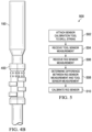
- FIG. 1 is a drawing of an example well system in accordance with an embodiment of the present disclosure.
- FIG. 2 is a drawing of a sensor calibration tool in accordance with an embodiment of the present disclosure.
- FIG. 3 is a drawing of a sensor bank on a sensor calibration tool in accordance with an embodiment of the present disclosure.
- FIGS. 4 A and 4 B are drawings of a sensor calibration tool in accordance with an alternative embodiment of the present disclosure.
- FIG. 5 is a process flow diagram of a method for determining an accuracy of a rig sensor in accordance with an embodiment of the present disclosure.
- Sensors that measure such operational parameters are typically positioned on various surface components of the rig system.
- the kind, location, and accuracy of rig sensors can vary greatly with different well systems in different locations and different kinds and types of equipment and sensors.
- Different skill levels of crew members can also contribute to differences in operational parameter information received by the operator from the rig sensors.
- an instrumented sub comprising a sensor calibration tool housing one or multiple tool sensors can be attached to the drill string.
- Each of the tool sensors on the sensor calibration tool can measure an operational parameter that is also measured by a corresponding rig sensor that is positioned on a surface component.
- Sensor data from the rig sensors and the tool sensors can be captured by a data gathering and analysis module and displayed for the operator on a display screen.
- the system can be configured to alert the operator if differences between the rig sensor measurement and the tool sensor measurement exceed a threshold value.
- rig sensors Based on the sensor data and comparison information provided by the system, rig sensors can be calibrated and/or otherwise adjusted and managed to enhance sensor data accuracy.
- Properly calibrated and accurate rig sensors can contribute to a higher rate-of-penetration and avoid drill string failure and/or other conditions or events that can result in lost time and increased costs.
- the sensor calibration tool can be easily attached or detached from the drill string and carried to a different wellsite, such that the system with the same tool sensor suite can be utilized at multiple drilling locations, thus minimizing time and costs and allowing for consistent sensor calibration procedures and results.
- the sensor calibration tool and system can be brought to a wellsite in response to an incident such as stuck pipe or twist off and installed on the well system to determine whether and the extent to which any rig sensors are out-of-calibration or otherwise inaccurate.
- Historical data related to the incident can be analyzed and corrected if necessary utilizing data from the sensor calibration tool.
- Data from the sensor calibration tool can be utilized in preventative tools such as machine learning algorithms for automated operations or rig crew training.
- FIG. 1 illustrates a well system 100 in accordance with one embodiment of the present disclosure.
- Well system 100 includes a conventional rotary land rig.
- the present disclosure is applicable to other types of onshore or offshore drilling rigs (including top drive, power swivel, down hole motor, and coiled tubing units) and to other drilling and/or production rigs or platforms that are operable to bore through the earth and/or produce hydrocarbons or other resources from the earth.
- Well system 100 includes a surface rig system 102 and a drill string 150 .
- Surface rig system 102 includes several surface components at or near the surface, including a derrick 104 that is supported above a rig floor 106 . In other embodiments, a mast may be used in lieu of a derrick 104 .
- Surface rig system 102 further includes a lifting gear that includes a crown block 108 mounted to the derrick 104 , a travelling block 110 , a hook 116 , and a swivel 118 .
- the crown block 108 and the travelling block 110 are interconnected by a cable 112 that is driven by draw works 114 to control the upward and downward movement of the travelling block 110 .
- Travelling block 110 carries hook 116 from which is suspended swivel 118 .
- the swivel 118 supports a top drive 138 , which is also a surface component of surface rig system 102 .
- Other surface components of surface rig system 102 include slips 122 , mud pumps 124 , stand pipe line 132 , and mud tanks 128 , described in more detail below.
- surface rig system 102 can include other, more, and/or fewer surface components.
- Drill string 150 includes drill pipe 154 (which comprises a plurality of interconnected drill pipe sections), and further includes a saver sub 152 at the top (uphole) end of drill string 150 and a bottom-hole assembly (BHA) 156 at the downhole end of drill string 150 .
- BHA 156 includes a drill bit 158 and a mud motor 160 , and may also include stabilizers, drill collars, measurement well drilling (MWD) instruments, and the like.
- Drill string 150 is positioned at least partially in well bore 101 .
- the top of drill string 150 specifically, saver sub 152 , is attached to top drive 138 .
- surface rig system 102 supports drill string 150 .
- the weight of drill string 150 may be further supported by slips 122 .
- Surface rig system 102 also pumps drilling fluid, or mud, 126 , down drill string 150 . More specifically, mud pumps 124 draw drilling fluid 126 from mud tanks 128 through stand pipe line 132 . The drilling fluid 126 is delivered to the drill string 150 through stand pipe line 132 which connects to swivel 118 . From the swivel 118 , the drilling fluid 126 travels through the drill string 150 to the BHA 156 , where it turns the mud motor 160 and exits the bit 158 to scour the formation and lift the resultant cuttings through the annulus to the surface. At the surface, mud tanks 128 receive the drilling fluid 126 from the well bore 101 through a flow line 134 . The mud tanks 128 and/or flow line 134 can include a shaker or other device to remove the cuttings.
- Drilling is accomplished by rotating the drill string 150 , which in turn rotates the bit 158 , and applying weight on bit 158 .
- Surface rig system 102 and specifically, top drive 138 , provides the rotation to drill string 150 within bore hole 101 .
- a down hole motor may rotate the bit 158 independently of the drill string 150 and the top drive 138 .
- the cuttings produced as bit 158 drills into the earth are carried out of bore hole 101 by the drilling fluid 126 supplied by pumps 124 .
- a drilling rig may include a rotary table at the rig floor instead of a top drive.
- the rotary table is part of the surface rig system and provides the rotation to drill string 150 during drilling operations.
- a hook load rig sensor 170 can attached to draw works 114 to measure the weight supported by draw works 114 .
- Hook load rig sensor 170 can be attached at or near the “dead end” of cable 112 or another suitable location.
- additional rig sensors that measure other operational parameters are positioned on other surface components of surface rig system 102 .
- fluid pressure rig sensor 172 can be disposed on or within stand pipe line 132 to measure a pressure of drilling fluid 126 fluid pumped through a stand pipe line 132 and down drill string 150 .
- a flow rig sensor 174 can be disposed one or within mud pumps 124 to measure the rate of flow of drilling fluid 126 pumped by mud pumps 124 through stand pipe line 132 and down drill string 150 .
- flow rig sensor 174 can detect the number of strokes per minute of mud pumps 124 instead of or in addition to the flow rate.
- a temperature rig sensor 176 can be disposed on or within mud pumps 124 to measure a temperature of drilling fluid 126 .
- one or more sensors can be attached to top drive 138 .
- a torque rig sensor 178 can be attached to top drive 138 to measure a torque load of the drill string.
- a revolutions-per-minute (RPM) rig sensor 180 can be attached to top drive 138 to measure a frequency of rotation of the drill string.
- a vibration rig sensor 182 can be attached to top drive 138 to measure vibration at or near the top of drill string 150 .
- An acoustic rig sensor 184 can be attached to top drive 138 to measure noise or other acoustic signals at or near the top of drill string 150 .
- the torque, RPM, vibration, and acoustic rig sensors can be attached to or near the rotary table instead of top drive 138 .
- Vibration and/or acoustic rig sensors can also be attached to other surface components of surface rig system 102 .
- all of the above-described rig sensors are attached to the surface components of surface rig system 102 as described above. In other embodiments, only one or some of the above-described rig sensors are attached to the surface rig system 102 components. In some embodiments, additional or other rig sensors can be included to measure the above-described or other operational parameters, and/or rig sensors can be placed within, on, or near different or additional surface components of surface rig system 102 than the ones described above.
- a sensor calibration tool 162 can be attached to drill string 150 .
- sensor calibration tool 162 can house a tool sensor bank which can include one or more tool sensors which can measure operational parameters such as drill string weight, torque, revolutions-per-minute (RPM) of the drill string, drilling fluid pressure, drilling fluid flow, drilling fluid temperature, drill string vibrations, noise, tension, compression, drag, and/or pipe bending.
- Sensor calibration tool 162 can be attached to drill string 150 before insertion of drill string 150 into wellbore 101 or after at least a portion of drill string 150 is disposed at least partially within wellbore 101 .
- data from the tool sensors on sensor calibration tool 162 can be compared to data from the rig sensors on the surface components of surface rig system 102 , the accuracy of the rig sensors can be analyzed and sensors calibrated or otherwise adjusted as necessary so as to optimize drilling operations.
- sensor calibration tool 162 can include, in addition to a sensor bank including one or multiple tool sensors, a communication module to transmit the tool sensor data.
- the communication module which can include a wireless transmitter (such as wi-fi, Bluetooth, laser, or acoustic) or other suitable data transmission means.
- sensor calibration tool 162 can also include a memory module to store historical or current sensor data from the tool sensors.
- Sensor calibration tool 162 can also include a power module to provide power to the tool sensors and/or the communication module and/or memory module.
- Well system 100 also includes a data gathering and analysis module 190 to receive and/or analyze sensor data from the rig sensor or sensors and the tool sensor or sensors, as described in further detail below.
- Data gathering and analysis module 190 can include a wireless reader or other receiver to download information from sensor calibration tool 162 such as sensor data from tool sensors of sensor calibration tool 162 .
- Data gathering and analysis module 190 can also be configured to receive data from one, some, or all of the rig sensors of surface rig system 102 , via wired or wireless connection.
- data gathering and analysis module 190 includes a computer system that comprises one or more processors, and a computer-readable medium (for example, a non-transitory computer-readable medium) storing computer instructions executable by the one or more processors to perform operations.
- data gathering and analysis module 190 is configured to receive display sensor data received from the rig sensors and/or the tool sensors and transmit the information to data display screen 192 , which can provide the information to an operation using a graphical user interface (GUI) or other suitable user interface.
- GUI graphical user interface
- Sensor data from a rig sensor of a surface component of surface rig system 102 can be displayed next to sensor data from a tool sensor on sensor calibration tool 162 for the same operational parameter.
- An operator observing a difference in the sensor data between the rig sensor and the corresponding tool sensor can take a suitable action such as calibrating or otherwise adjusting the rig sensor and/or replacing a failed rig sensor.
- sensor calibration tool 162 can include a weight sensor which provides information regarding the weight of drill string 150 . Measurements from the weight tool sensor can be displayed next to data from hook load rig sensor 170 on draw works 114 . Sensor calibration tool 162 can also include a tool sensor that is an RPM sensor to measure the RPM of drill string 150 , and measurements from this RPM tool sensor can be displayed next to data from RPM rig sensor 180 on top drive 138 . Values from other tool sensors on sensor calibration tool 162 can likewise be displayed next to corresponding values for the same operational parameter from rig sensors on surface rig system 102 .
- sensor calibration tool 162 while attached to drill string 150 , sensor calibration tool 162 is positioned at a surface location proximate to surface rig system 102 and the tool sensor measurements and rig sensor measurements can be transmitted and received while the tool is positioned at this surface location. In some embodiments, sensor calibration tool 162 is positioned above rig floor 106 . In some embodiments, sensor calibration tool 162 can be positioned at a near-surface location some distance downhole, for example, within about 300 feet of the surface. For example, in the embodiment illustrated in FIG. 1 , sensor calibration tool 162 is positioned on the drill string just above rig floor 106 and is proximate to surface components of surface rig system 102 such as top drive 138 , draw works 114 , and mud pumps 124 .
- Such a surface position allows for data from sensor calibration tool to be most easily, quickly, and accurately transmitted to data gathering and analysis module 190 and/or otherwise accessed via wireless transmission or other means. Also, so positioned at a surface location, data from the tool sensors on sensor calibration tool 162 can in some embodiments be more accurately and directly compared to the data from the nearby rig sensors of surface rig system 102 , for a given operational parameter. In some embodiments, locating sensor calibration tool 162 at a surface location can result in more accurate torque measurements, as no frictional losses from rubbing of the tool against the wellbore would be required to be taken into account. In some embodiments, sensor calibration tool 162 can be positioned at a surface location and drill pipes 154 added to drill string 150 below sensor calibration tool 162 , and so positioned can provide measurements of the weight of individual drill pipes 154 as they are added to the drill string.
- sensor calibration tool 162 can be removed from drill string 150 before sensor calibration tool 162 descends into (or further into) wellbore 101 . In some embodiments, sensor calibration tool 162 can then be reattached at a higher point on drill string 150 to maintain the position of sensor calibration tool 162 at a surface location as drilling operations continue. In some embodiments, sensor calibration tool 162 is attached to saver sub 152 and drill pipes 154 added beneath sensor calibration tool 162 , such that sensor calibration tool 162 remains at a surface location as drill pipes 154 and other portions of drill string 150 are lowered into wellbore 101 . In some embodiments, sensor calibration tool 162 is lowered into wellbore 101 along with other components of drill string 150 as drill string 150 travels further downhole.
- sensor calibration tool 162 can be configured as a threaded sub or a clamp that can be readily and easily attached and/or detached from drill string 150 . In this way, sensor calibration tool 162 can continue to be positioned at a surface location. Also, because it is easily attachable and detachable, sensor calibration tool 162 can be easily deployed at different well sites, thus minimizing time and costs and allowing for consistent sensor results and consistent calibration procedures and results for different well systems.
- data gathering and analysis module 190 and display screen 192 can be portable units. In some embodiments, some of the gathering and analysis functions of data gathering and analysis module 190 can be performed in a cloud or edge network.
- data gathering and analysis module 190 can adjust the measurements from the rig sensors and/or the tool sensors so as to make the measurements more directly comparable.
- a measurement from hook load rig sensor 170 on draw works 114 can be adjusted by removing (manually or automatically) the known weight of travelling block 110 , hook 116 , swivel 118 , and top drive 138 such that what is left represents the weight of drill string 150 and can be more directly compared to the measurement of the weight of drill string 150 from the weight sensor on sensor calibration tool 162 .
- no adjustment is necessary because any adjustment would be within the margin of error of the sensor.
- sensor data can be streamed and displayed in real time, and can include single measurements and/or multiple measurements over time.
- historical sensor data can be downloaded from sensor calibration tool 162 to data gathering and analysis module 190 and retrieved by the operator from data gathering and analysis module 190 as needed by inputting retrieval commands.
- data gathering and analysis module 190 can be configured to analyze the sensor data and provide alerts the operator when a calibration is required and/or perform other actions. For example, data gathering and analysis module 190 can be configured to calculate the difference between a measurement from a tool sensor on sensor calibration tool 162 of an operational parameter and the corresponding rig sensor measurement (from a rig sensor on a surface component of surface rig system 102 ) of that operational parameter. Some difference may be an acceptable operational variation, but a greater difference may be an unacceptable variation indicating an out-of-calibration sensor or other condition requiring action by the operator. In some embodiments, data gathering and analysis module 190 can store a threshold value of the difference, above which above which calibration or another action is required. A difference below the threshold value would not trigger an alert; a difference above the threshold value would trigger an alert.
- the operator can calibrate the rig sensor as necessary in light of the data from the sensor calibration tool 162 .
- Such calibration can be done manually or automatically.
- data gathering and analysis module 190 can be configured to measure and record the standard deviation between tool sensor data and rig sensor data. In some embodiments, data gathering and analysis module 190 can be configured to store historical data including values from the rig sensors and the tool sensors and/or standard deviation data. In some embodiments, data gathering and analysis module 190 can be configured to compare historical data from rig sensors with historical data from tool sensors of their respective operational parameters. In some embodiments, data gathering and analysis module 190 can adjust or correct historical rig sensor data based on this comparison with historical or current tool sensor data and provide the operator with an output comprising such adjusted or corrected historical sensor rig data.
- sensor data from sensor calibration tool 162 can be used to train machine learning algorithms and/or otherwise used to understand and optimize drill string behavior and/or drilling optimization.
- the sensor calibration tool and system can be brought to a wellsite in response to an incident such as stuck pipe or twist off and installed on the well system to determine whether and the extent to which any rig sensors are out-of-calibration or otherwise inaccurate.
- the system and method can be brought to each of those wells such that historical data related to the incidents at the different wells can be analyzed, corrected, and compared using a common tool and system.
- FIG. 2 is a drawing of sensor calibration tool 162 in accordance with an embodiment of the present disclosure.
- sensor calibration tool 162 is an instrumented sub including a mandrel 202 , an upper connection 204 , and a lower connection 206 .
- Upper connection 204 and lower connection 206 can comprise threaded connections that can be attached to threaded drill pipe segments of drill string 150 using known methods.
- sensor calibration tool 162 can be attached to drill pipe segment or segments that are in a mouse hole at the rig, and the drill pipe and tool combination then attached to drill string 150 .
- sensor calibration tool 162 can be threaded directly to a drill pipe that is already attached to drill string 150 .
- Sensor calibration tool 162 as shown in FIG. 2 also includes a sensor bank 210 that includes multiple individual tool sensors to measure operational parameters, as described above. Sensor bank 210 is described in further detail in FIG. 3 .
- Sensor calibration tool 162 also includes power source 212 which can include one or more batteries. In some embodiments, power can be provided from another source (for example, a power cable and/or a fluid turbine) in lieu of or in addition to batteries.
- Communication module 214 can include a wireless transmitter (such as wi-fi, Bluetooth, laser, or acoustic) or other suitable means for transmitting sensor data.
- Sensor calibration tool 162 can further include a memory module (not shown). In some embodiments, the memory module can comprise a SDD or HDD or similar memory system and a USB interface.
- FIG. 3 is a drawing of a sensor bank on a sensor calibration tool 162 in accordance with an embodiment of the present disclosure. The features of sensor bank the sensor bank illustrated in FIG. 3 are described in reference to the elements described in reference to FIGS. 1 and 2 .
- the sensor bank illustrated in FIG. 3 is sensor bank 210 of FIG. 2 and is disposed on mandrel 202 .
- sensor bank 210 includes eight tool sensors: weight tool sensor 310 , fluid pressure tool sensor 312 , flow tool sensor 314 , temperature tool sensor 316 , torque tool sensor 318 , RPM tool sensor 320 , vibration tool sensor 322 , acoustic tool sensor 324 .
- Each tool sensor can measure a respective operational parameter.
- sensor bank 210 may include a different number (for example, fewer) tool sensors and/or sensors for different and/or additional operational parameters than as described above. Sensor data from the tool sensors can be compared to rig sensor data for the corresponding operational parameter, as described above in reference to FIG. 1 .
- weight tool sensor 310 can measure the weight of drill string 150 , and data from weight tool sensor 310 can be compared to data from hook load rig sensor 170 .
- Fluid pressure tool sensor 312 can measure the pressure of drilling fluid flowing through drill string 150 , and data from fluid pressure tool sensor 312 can be compared to data from fluid pressure rig sensor 172 .
- Flow tool sensor 314 can measure the flow rate of drilling fluid flowing through drill string 150 and data from flow tool sensor 314 can be compared to data from flow rig sensor 174 .
- Temperature tool sensor 316 can measure the temperature of drilling fluid flowing through drill string 150 , and data from temperature tool sensor 316 can be compared to data from temperature rig sensor 176 .
- Torque tool sensor 318 can measure a torque load of drill string 150 , and data from torque tool sensor 318 can be compared to data from torque rig sensor 178 .
- RPM tool sensor 320 can measure the frequency of rotation of drill string 150 , and data from RPM tool sensor 320 can be compared to data from RPM rig sensor 180 .
- Vibration tool sensor 322 can measure vibrations of drill string 150 , and data from vibration tool sensor 322 can be compared to data from vibration rig sensor 182 .
- Acoustic tool sensor 324 can measure noise or other acoustic signals at or near the top of drill string 150 , and data from acoustic tool sensor 324 can be compared to data from acoustic rig sensor 184 .
- FIGS. 4 A and 4 B are drawings of a sensor calibration tool in accordance with an alternative embodiment of the present disclosure.
- the sensor calibration tool is configured as a clamp that can be attached to the exterior of drill string 150 .
- sensor calibration clamp tool 400 includes a body 402 that splits in half. In FIG. 4 A , sensor calibration clamp tool 400 is in an open position revealing interior surface 403 . Interior surface 403 includes latching mechanisms 404 which are configured to attach to an exterior surface of a drill string (such as drill string 150 of FIG. 1 ), as shown in FIG. 4 B .
- a drill string such as drill string 150 of FIG. 1
- sensor calibration clamp tool 400 includes a sensor bank 210 , a power source 212 , and a communication module 214 .
- Sensor bank 210 , power source 212 , and communication module 214 have a structure and function as described in reference to FIG. 3 .
- Sensor calibration clamp tool 400 can, in some embodiments, be more easily attachable and detachable from the drill string than sensor calibration tool 162 , resulting in further cost and time savings.
- sensor bank 210 of sensor calibration clamp tool 400 may have the same suite of tool sensors as sensor calibration tool 162 .
- sensor bank 210 of calibration clamp tool 400 may have a different suite and/or a different number of tool sensors than the sensor bank of sensor calibration tool 162 .
- sensor calibration clamp tool 400 can include tool sensors for torque, RPM, and vibration, but not include sensors for flow, pressure, and/or temperature.
- FIG. 5 is a process flow diagram of a method for determining an accuracy of a rig sensor in accordance with an embodiment of the present disclosure. The method is described with reference to the components described in reference to FIGS. 1 - 2 .
- method 500 begins at block 502 with attaching a sensor calibration tool (such as sensor calibration tool 162 ) to a drill string (such as drill string 150 ).
- a sensor calibration tool such as sensor calibration tool 162
- the sensor calibration tool includes on or many tool sensors, each of which is configured to measure a respective operational parameter.
- the drill string can be disposed at least partially within a wellbore and supported by a surface rig system and the sensor calibration tool can be positioned on the drill string at a surface location proximate to the surface rig system.
- a receiver such as a data gathering and analysis module 190 receives a tool sensor measurement of the respective operational parameter from one of the tool sensors.
- the data gathering and analysis module or other suitable receiver receives a rig sensor measurement from a rig sensor positioned on a surface component of the surface rig system, of the same operational parameter that was also measured by the tool sensor operational parameter
- a difference between the rig sensor measurement and the tool sensor measurement is determined. This can be done manually by an operator or automatically by the data gathering and analysis module.
- the difference can be compared to a difference threshold. If the difference threshold is exceeded, the data gathering and analysis module can transmit an alert to the operator.
- the rig sensor is calibrated based on the comparison of the tool sensor measurement with the rig sensor measurement. Calibration can be done manually or automatically as described in reference to FIG. 1 .
- “approximately” or “substantially” means a deviation or allowance of up to 10 percent (%) and any variation from a mentioned value is within the tolerance limits of any machinery used to manufacture the part.
- “about” can also allow for a degree of variability in a value or range, for example, within 10%, within 5%, or within 1% of a stated value or of a stated limit of a range.
Abstract
Description
Claims (20)
Priority Applications (3)
| Application Number | Priority Date | Filing Date | Title |
|---|---|---|---|
| US17/148,378 US11697991B2 (en) | 2021-01-13 | 2021-01-13 | Rig sensor testing and calibration |
| PCT/US2022/012290 WO2022155317A1 (en) | 2021-01-13 | 2022-01-13 | Rig sensor testing and calibration |
| EP22702568.1A EP4278062A1 (en) | 2021-01-13 | 2022-01-13 | Rig sensor testing and calibration |
Applications Claiming Priority (1)
| Application Number | Priority Date | Filing Date | Title |
|---|---|---|---|
| US17/148,378 US11697991B2 (en) | 2021-01-13 | 2021-01-13 | Rig sensor testing and calibration |
Publications (2)
| Publication Number | Publication Date |
|---|---|
| US20220220845A1 US20220220845A1 (en) | 2022-07-14 |
| US11697991B2 true US11697991B2 (en) | 2023-07-11 |
Family
ID=80225490
Family Applications (1)
| Application Number | Title | Priority Date | Filing Date |
|---|---|---|---|
| US17/148,378 Active 2041-07-04 US11697991B2 (en) | 2021-01-13 | 2021-01-13 | Rig sensor testing and calibration |
Country Status (3)
| Country | Link |
|---|---|
| US (1) | US11697991B2 (en) |
| EP (1) | EP4278062A1 (en) |
| WO (1) | WO2022155317A1 (en) |
Citations (433)
| Publication number | Priority date | Publication date | Assignee | Title |
|---|---|---|---|---|
| US891957A (en) | 1907-06-24 | 1908-06-30 | Otto Schubert | Cowl. |
| US2043225A (en) | 1935-07-05 | 1936-06-09 | Arthur L Armentrout | Method and apparatus for testing the productivity of the formation in wells |
| US2110913A (en) | 1936-08-22 | 1938-03-15 | Hall And Lowrey Inc | Pipe cutting apparatus |
| US2227729A (en) | 1939-09-30 | 1941-01-07 | Lynes John | Packer and sampling assembly |
| US2286673A (en) | 1941-06-10 | 1942-06-16 | Leslie A Douglas | Means for extracting the pore content of subterranean strata |
| US2305062A (en) | 1940-05-09 | 1942-12-15 | C M P Fishing Tool Corp | Cementing plug |
| US2344120A (en) | 1941-04-21 | 1944-03-14 | Baker Oil Tools Inc | Method and apparatus for cementing wells |
| US2509608A (en) | 1947-04-28 | 1950-05-30 | Shell Dev | Formation tester |
| US2688369A (en) | 1949-06-16 | 1954-09-07 | W B Taylor | Formation tester |
| US2690897A (en) | 1950-11-27 | 1954-10-05 | Jr Robert E Clark | Combination mill and under-reamer for oil wells |
| US2719363A (en) | 1953-01-19 | 1955-10-04 | Montgomery Richard Franklin | Calipering method and apparatus |
| US2757738A (en) | 1948-09-20 | 1956-08-07 | Union Oil Co | Radiation heating |
| US2795279A (en) | 1952-04-17 | 1957-06-11 | Electrotherm Res Corp | Method of underground electrolinking and electrocarbonization of mineral fuels |
| US2799641A (en) | 1955-04-29 | 1957-07-16 | John H Bruninga Sr | Electrolytically promoting the flow of oil from a well |
| US2805045A (en) | 1953-06-08 | 1957-09-03 | Globe Oil Tools Co | Well drilling bit |
| US2822150A (en) | 1955-04-18 | 1958-02-04 | Baker Oil Tools Inc | Rotary expansible drill bits |
| US2841226A (en) | 1953-11-24 | 1958-07-01 | Baker Oil Tools Inc | Well bore conduit centering apparatus |
| US2899000A (en) | 1957-08-05 | 1959-08-11 | Houston Oil Field Mat Co Inc | Piston actuated casing mill |
| US2927775A (en) | 1957-12-10 | 1960-03-08 | Jersey Prod Res Co | Unconsolidated formation core barrel |
| US3016244A (en) | 1954-07-29 | 1962-01-09 | Protona Productionsgesellschaf | Miniature magnetic sound recording and reproducing device |
| US3028915A (en) | 1958-10-27 | 1962-04-10 | Pan American Petroleum Corp | Method and apparatus for lining wells |
| US3087552A (en) | 1961-10-02 | 1963-04-30 | Jersey Prod Res Co | Apparatus for centering well tools in a well bore |
| US3102599A (en) | 1961-09-18 | 1963-09-03 | Continental Oil Co | Subterranean drilling process |
| US3103975A (en) | 1959-04-10 | 1963-09-17 | Dow Chemical Co | Communication between wells |
| US3104711A (en) | 1963-09-24 | haagensen | ||
| US3114875A (en) | 1961-05-04 | 1963-12-17 | Raytheon Co | Microwave device for testing formations surrounding a borehole having means for measuring the standing wave ratio of energy incident to and reflected from the formations |
| US3133592A (en) | 1959-05-25 | 1964-05-19 | Petro Electronics Corp | Apparatus for the application of electrical energy to subsurface formations |
| US3137347A (en) | 1960-05-09 | 1964-06-16 | Phillips Petroleum Co | In situ electrolinking of oil shale |
| US3149672A (en) | 1962-05-04 | 1964-09-22 | Jersey Prod Res Co | Method and apparatus for electrical heating of oil-bearing formations |
| US3169577A (en) | 1960-07-07 | 1965-02-16 | Electrofrac Corp | Electrolinking by impulse voltages |
| US3170519A (en) | 1960-05-11 | 1965-02-23 | Gordon L Allot | Oil well microwave tools |
| US3211220A (en) | 1961-04-17 | 1965-10-12 | Electrofrac Corp | Single well subsurface electrification process |
| US3220478A (en) | 1960-09-08 | 1965-11-30 | Robert B Kinzbach | Casing cutter and milling tool |
| US3236307A (en) | 1962-01-11 | 1966-02-22 | Brown Oil Tools | Method and apparatus for releasing wall-stuck pipe |
| US3253336A (en) | 1963-10-17 | 1966-05-31 | Brown Oil Tools | Rotary pipe cutting device having pipe clamping means and ratchet feed means for thecutter |
| US3268003A (en) | 1963-09-18 | 1966-08-23 | Shell Oil Co | Method of releasing stuck pipe from wells |
| US3331439A (en) | 1964-08-14 | 1967-07-18 | Sanford Lawrence | Multiple cutting tool |
| US3428125A (en) | 1966-07-25 | 1969-02-18 | Phillips Petroleum Co | Hydro-electropyrolysis of oil shale in situ |
| US3468373A (en) | 1968-01-02 | 1969-09-23 | Samuel H Smith | Apparatus for severing well casing in a submarine environment |
| US3522848A (en) | 1967-05-29 | 1970-08-04 | Robert V New | Apparatus for production amplification by stimulated emission of radiation |
| US3547193A (en) | 1969-10-08 | 1970-12-15 | Electrothermic Co | Method and apparatus for recovery of minerals from sub-surface formations using electricity |
| US3547192A (en) | 1969-04-04 | 1970-12-15 | Shell Oil Co | Method of metal coating and electrically heating a subterranean earth formation |
| US3642066A (en) | 1969-11-13 | 1972-02-15 | Electrothermic Co | Electrical method and apparatus for the recovery of oil |
| US3656564A (en) | 1970-12-03 | 1972-04-18 | Cicero C Brown | Apparatus for rotary drilling of wells using casing as the drill pipe |
| US3696866A (en) | 1971-01-27 | 1972-10-10 | Us Interior | Method for producing retorting channels in shale deposits |
| US3839791A (en) | 1973-02-13 | 1974-10-08 | Compac Cutting Machine Corp | Pipe cutting and preping device |
| US3862662A (en) | 1973-12-12 | 1975-01-28 | Atlantic Richfield Co | Method and apparatus for electrical heating of hydrocarbonaceous formations |
| US3874450A (en) | 1973-12-12 | 1975-04-01 | Atlantic Richfield Co | Method and apparatus for electrically heating a subsurface formation |
| JPS5013156B1 (en) | 1970-12-23 | 1975-05-17 | ||
| US3931856A (en) | 1974-12-23 | 1976-01-13 | Atlantic Richfield Company | Method of heating a subterranean formation |
| US3946809A (en) | 1974-12-19 | 1976-03-30 | Exxon Production Research Company | Oil recovery by combination steam stimulation and electrical heating |
| US3948319A (en) | 1974-10-16 | 1976-04-06 | Atlantic Richfield Company | Method and apparatus for producing fluid by varying current flow through subterranean source formation |
| US4008762A (en) | 1976-02-26 | 1977-02-22 | Fisher Sidney T | Extraction of hydrocarbons in situ from underground hydrocarbon deposits |
| US4010799A (en) | 1975-09-15 | 1977-03-08 | Petro-Canada Exploration Inc. | Method for reducing power loss associated with electrical heating of a subterranean formation |
| US4064211A (en) | 1972-12-08 | 1977-12-20 | Insituform (Pipes & Structures) Ltd. | Lining of passageways |
| US4084637A (en) | 1976-12-16 | 1978-04-18 | Petro Canada Exploration Inc. | Method of producing viscous materials from subterranean formations |
| US4135579A (en) | 1976-05-03 | 1979-01-23 | Raytheon Company | In situ processing of organic ore bodies |
| US4140179A (en) | 1977-01-03 | 1979-02-20 | Raytheon Company | In situ radio frequency selective heating process |
| US4140180A (en) | 1977-08-29 | 1979-02-20 | Iit Research Institute | Method for in situ heat processing of hydrocarbonaceous formations |
| US4144935A (en) | 1977-08-29 | 1979-03-20 | Iit Research Institute | Apparatus and method for in situ heat processing of hydrocarbonaceous formations |
| US4191493A (en) | 1977-07-14 | 1980-03-04 | Aktiebolaget Platmanufaktur | Method for the production of a cavity limited by a flexible material |
| US4193451A (en) | 1976-06-17 | 1980-03-18 | The Badger Company, Inc. | Method for production of organic products from kerogen |
| US4193448A (en) | 1978-09-11 | 1980-03-18 | Jeambey Calhoun G | Apparatus for recovery of petroleum from petroleum impregnated media |
| US4196329A (en) | 1976-05-03 | 1980-04-01 | Raytheon Company | Situ processing of organic ore bodies |
| US4199025A (en) | 1974-04-19 | 1980-04-22 | Electroflood Company | Method and apparatus for tertiary recovery of oil |
| US4265307A (en) | 1978-12-20 | 1981-05-05 | Standard Oil Company | Shale oil recovery |
| USRE30738E (en) | 1980-02-06 | 1981-09-08 | Iit Research Institute | Apparatus and method for in situ heat processing of hydrocarbonaceous formations |
| US4301865A (en) | 1977-01-03 | 1981-11-24 | Raytheon Company | In situ radio frequency selective heating process and system |
| US4320801A (en) | 1977-09-30 | 1982-03-23 | Raytheon Company | In situ processing of organic ore bodies |
| US4334928A (en) | 1976-12-21 | 1982-06-15 | Sumitomo Electric Industries, Ltd. | Sintered compact for a machining tool and a method of producing the compact |
| US4337653A (en) | 1981-04-29 | 1982-07-06 | Koomey, Inc. | Blowout preventer control and recorder system |
| US4343651A (en) | 1979-03-29 | 1982-08-10 | Sumitomo Electric Industries, Ltd. | Sintered compact for use in a tool |
| US4354559A (en) | 1980-07-30 | 1982-10-19 | Tri-State Oil Tool Industries, Inc. | Enlarged borehole drilling method and apparatus |
| US4373581A (en) | 1981-01-19 | 1983-02-15 | Halliburton Company | Apparatus and method for radio frequency heating of hydrocarbonaceous earth formations including an impedance matching technique |
| US4394170A (en) | 1979-11-30 | 1983-07-19 | Nippon Oil And Fats Company, Limited | Composite sintered compact containing high density boron nitride and a method of producing the same |
| US4396062A (en) | 1980-10-06 | 1983-08-02 | University Of Utah Research Foundation | Apparatus and method for time-domain tracking of high-speed chemical reactions |
| US4412585A (en) | 1982-05-03 | 1983-11-01 | Cities Service Company | Electrothermal process for recovering hydrocarbons |
| US4413642A (en) | 1977-10-17 | 1983-11-08 | Ross Hill Controls Corporation | Blowout preventer control system |
| GB2124855A (en) | 1982-08-03 | 1984-02-22 | Deutsche Tiefbohr Ag | Remote control and monitoring of well shut-off systems |
| US4449585A (en) | 1982-01-29 | 1984-05-22 | Iit Research Institute | Apparatus and method for in situ controlled heat processing of hydrocarbonaceous formations |
| US4457365A (en) | 1978-12-07 | 1984-07-03 | Raytheon Company | In situ radio frequency selective heating system |
| US4470459A (en) | 1983-05-09 | 1984-09-11 | Halliburton Company | Apparatus and method for controlled temperature heating of volumes of hydrocarbonaceous materials in earth formations |
| US4476926A (en) | 1982-03-31 | 1984-10-16 | Iit Research Institute | Method and apparatus for mitigation of radio frequency electric field peaking in controlled heat processing of hydrocarbonaceous formations in situ |
| US4484627A (en) | 1983-06-30 | 1984-11-27 | Atlantic Richfield Company | Well completion for electrical power transmission |
| US4485869A (en) | 1982-10-22 | 1984-12-04 | Iit Research Institute | Recovery of liquid hydrocarbons from oil shale by electromagnetic heating in situ |
| US4485868A (en) | 1982-09-29 | 1984-12-04 | Iit Research Institute | Method for recovery of viscous hydrocarbons by electromagnetic heating in situ |
| US4487257A (en) | 1976-06-17 | 1984-12-11 | Raytheon Company | Apparatus and method for production of organic products from kerogen |
| US4495990A (en) | 1982-09-29 | 1985-01-29 | Electro-Petroleum, Inc. | Apparatus for passing electrical current through an underground formation |
| US4498535A (en) | 1982-11-30 | 1985-02-12 | Iit Research Institute | Apparatus and method for in situ controlled heat processing of hydrocarbonaceous formations with a controlled parameter line |
| US4499948A (en) | 1983-12-12 | 1985-02-19 | Atlantic Richfield Company | Viscous oil recovery using controlled pressure well pair drainage |
| US4508168A (en) | 1980-06-30 | 1985-04-02 | Raytheon Company | RF Applicator for in situ heating |
| US4513815A (en) | 1983-10-17 | 1985-04-30 | Texaco Inc. | System for providing RF energy into a hydrocarbon stratum |
| US4524826A (en) | 1982-06-14 | 1985-06-25 | Texaco Inc. | Method of heating an oil shale formation |
| US4524827A (en) | 1983-04-29 | 1985-06-25 | Iit Research Institute | Single well stimulation for the recovery of liquid hydrocarbons from subsurface formations |
| US4545435A (en) | 1983-04-29 | 1985-10-08 | Iit Research Institute | Conduction heating of hydrocarbonaceous formations |
| US4553592A (en) | 1984-02-09 | 1985-11-19 | Texaco Inc. | Method of protecting an RF applicator |
| US4557327A (en) | 1983-09-12 | 1985-12-10 | J. C. Kinley Company | Roller arm centralizer |
| US4576231A (en) | 1984-09-13 | 1986-03-18 | Texaco Inc. | Method and apparatus for combating encroachment by in situ treated formations |
| US4583589A (en) | 1981-10-22 | 1986-04-22 | Raytheon Company | Subsurface radiating dipole |
| US4592423A (en) | 1984-05-14 | 1986-06-03 | Texaco Inc. | Hydrocarbon stratum retorting means and method |
| US4612988A (en) | 1985-06-24 | 1986-09-23 | Atlantic Richfield Company | Dual aquafer electrical heating of subsurface hydrocarbons |
| US4620593A (en) | 1984-10-01 | 1986-11-04 | Haagensen Duane B | Oil recovery system and method |
| US4636934A (en) | 1984-05-21 | 1987-01-13 | Otis Engineering Corporation | Well valve control system |
| USRE32345E (en) | 1982-08-13 | 1987-02-03 | Completion Tool Company | Packer valve arrangement |
| US4660636A (en) | 1981-05-20 | 1987-04-28 | Texaco Inc. | Protective device for RF applicator in in-situ oil shale retorting |
| CA1226325A (en) | 1984-02-29 | 1987-09-01 | Richard F. Uhen | Lubricant slinger for an electric motor and method of assembling same |
| US4705108A (en) | 1986-05-27 | 1987-11-10 | The United States Of America As Represented By The United States Department Of Energy | Method for in situ heating of hydrocarbonaceous formations |
| US4817711A (en) | 1987-05-27 | 1989-04-04 | Jeambey Calhoun G | System for recovery of petroleum from petroleum impregnated media |
| US5012863A (en) | 1988-06-07 | 1991-05-07 | Smith International, Inc. | Pipe milling tool blade and method of dressing same |
| US5018580A (en) | 1988-11-21 | 1991-05-28 | Uvon Skipper | Section milling tool |
| US5037704A (en) | 1985-11-19 | 1991-08-06 | Sumitomo Electric Industries, Ltd. | Hard sintered compact for a tool |
| US5055180A (en) | 1984-04-20 | 1991-10-08 | Electromagnetic Energy Corporation | Method and apparatus for recovering fractions from hydrocarbon materials, facilitating the removal and cleansing of hydrocarbon fluids, insulating storage vessels, and cleansing storage vessels and pipelines |
| US5068819A (en) | 1988-06-23 | 1991-11-26 | International Business Machines Corporation | Floating point apparatus with concurrent input/output operations |
| US5070952A (en) | 1989-02-24 | 1991-12-10 | Smith International, Inc. | Downhole milling tool and cutter therefor |
| US5074355A (en) | 1990-08-10 | 1991-12-24 | Masx Energy Services Group, Inc. | Section mill with multiple cutting blades |
| US5082054A (en) | 1990-02-12 | 1992-01-21 | Kiamanesh Anoosh I | In-situ tuned microwave oil extraction process |
| US5092056A (en) | 1989-09-08 | 1992-03-03 | Halliburton Logging Services, Inc. | Reversed leaf spring energizing system for wellbore caliper arms |
| US5107931A (en) | 1990-11-14 | 1992-04-28 | Valka William A | Temporary abandonment cap and tool |
| US5107705A (en) | 1990-03-30 | 1992-04-28 | Schlumberger Technology Corporation | Video system and method for determining and monitoring the depth of a bottomhole assembly within a wellbore |
| US5228518A (en) | 1991-09-16 | 1993-07-20 | Conoco Inc. | Downhole activated process and apparatus for centralizing pipe in a wellbore |
| US5236039A (en) | 1992-06-17 | 1993-08-17 | General Electric Company | Balanced-line RF electrode system for use in RF ground heating to recover oil from oil shale |
| US5278550A (en) | 1992-01-14 | 1994-01-11 | Schlumberger Technology Corporation | Apparatus and method for retrieving and/or communicating with downhole equipment |
| US5319272A (en) | 1992-07-14 | 1994-06-07 | Eemco/Datron, Inc. | Miniature rotating rectifier assembly |
| US5388648A (en) | 1993-10-08 | 1995-02-14 | Baker Hughes Incorporated | Method and apparatus for sealing the juncture between a vertical well and one or more horizontal wells using deformable sealing means |
| WO1995035429A1 (en) | 1994-06-21 | 1995-12-28 | The Red Baron (Oil Tools Rental) Limited | Pipe cutter |
| US5490598A (en) | 1994-03-30 | 1996-02-13 | Drexel Oilfield Services, Inc. | Screen for vibrating separator |
| US5501248A (en) | 1994-06-23 | 1996-03-26 | Lmk Enterprises, Inc. | Expandable pipe liner and method of installing same |
| WO1997021904A2 (en) | 1995-12-14 | 1997-06-19 | Site Oil Tools Inc. | Open hole straddle system and method for setting such a system |
| CA2249432A1 (en) | 1996-03-19 | 1997-09-25 | Bj Services Company, Usa | Method and apparatus using coiled-in-coiled tubing |
| US5690826A (en) | 1996-05-10 | 1997-11-25 | Cravello; William Myron | Shaker screen assembly |
| US5803666A (en) | 1996-12-19 | 1998-09-08 | Keller; Carl E. | Horizontal drilling method and apparatus |
| US5803186A (en) | 1995-03-31 | 1998-09-08 | Baker Hughes Incorporated | Formation isolation and testing apparatus and method |
| US5813480A (en) | 1995-02-16 | 1998-09-29 | Baker Hughes Incorporated | Method and apparatus for monitoring and recording of operating conditions of a downhole drill bit during drilling operations |
| US5853049A (en) | 1997-02-26 | 1998-12-29 | Keller; Carl E. | Horizontal drilling method and apparatus |
| US5890540A (en) | 1995-07-05 | 1999-04-06 | Renovus Limited | Downhole tool |
| US5899274A (en) | 1996-09-18 | 1999-05-04 | Alberta Oil Sands Technology And Research Authority | Solvent-assisted method for mobilizing viscous heavy oil |
| US5947213A (en) | 1996-12-02 | 1999-09-07 | Intelligent Inspection Corporation | Downhole tools using artificial intelligence based control |
| US5955666A (en) | 1997-03-12 | 1999-09-21 | Mullins; Augustus Albert | Satellite or other remote site system for well control and operation |
| US5958236A (en) | 1993-01-13 | 1999-09-28 | Derrick Manufacturing Corporation | Undulating screen for vibratory screening machine and method of fabrication thereof |
| USRE36362E (en) | 1994-12-07 | 1999-11-02 | Jackson; William Evans | Polymer liners in rod pumping wells |
| US6012526A (en) | 1996-08-13 | 2000-01-11 | Baker Hughes Incorporated | Method for sealing the junctions in multilateral wells |
| US6032742A (en) | 1996-12-09 | 2000-03-07 | Hydril Company | Blowout preventer control system |
| US6041860A (en) | 1996-07-17 | 2000-03-28 | Baker Hughes Incorporated | Apparatus and method for performing imaging and downhole operations at a work site in wellbores |
| US6047239A (en) | 1995-03-31 | 2000-04-04 | Baker Hughes Incorporated | Formation testing apparatus and method |
| WO2000025942A1 (en) | 1998-10-30 | 2000-05-11 | Tuboscope I/P Inc. | A screen for use in a shale shaker |
| WO2000031374A1 (en) | 1998-11-19 | 2000-06-02 | Foy Streetman | Apparatus and method for enhancing fluid and gas recovery in a well |
| US6096436A (en) | 1996-04-04 | 2000-08-01 | Kennametal Inc. | Boron and nitrogen containing coating and method for making |
| US6170531B1 (en) | 1997-05-02 | 2001-01-09 | Karl Otto Braun Kg | Flexible tubular lining material |
| US6173795B1 (en) | 1996-06-11 | 2001-01-16 | Smith International, Inc. | Multi-cycle circulating sub |
| US6189611B1 (en) | 1999-03-24 | 2001-02-20 | Kai Technologies, Inc. | Radio frequency steam flood and gas drive for enhanced subterranean recovery |
| US6206108B1 (en) | 1995-01-12 | 2001-03-27 | Baker Hughes Incorporated | Drilling system with integrated bottom hole assembly |
| WO2001042622A1 (en) | 1999-12-09 | 2001-06-14 | Oxford Instruments Superconductivity Limited | Method and device for transferring data |
| GB2357305A (en) | 1999-12-13 | 2001-06-20 | George Stenhouse | Lining bores, such as wells and pipelines |
| US6254844B1 (en) | 1998-10-02 | 2001-07-03 | Agency Of Industrial Science & Technology, Ministry Of International Trade & Industry | Method for production of sintered lithium titaniumphosphate and sintered pellets obtained by the method |
| US6268726B1 (en) | 1998-01-16 | 2001-07-31 | Numar Corporation | Method and apparatus for nuclear magnetic resonance measuring while drilling |
| US6269953B1 (en) | 1993-04-30 | 2001-08-07 | Tuboscope I/P, Inc. | Vibratory separator screen assemblies |
| US6290068B1 (en) | 1993-04-30 | 2001-09-18 | Tuboscope I/P, Inc. | Shaker screens and methods of use |
| US6305471B1 (en) | 1998-05-19 | 2001-10-23 | Elmar Services, Ltd. | Pressure control apparatus |
| US6325216B1 (en) | 1993-04-30 | 2001-12-04 | Tuboscope I/P, Inc. | Screen apparatus for vibratory separator |
| US6328111B1 (en) | 1999-02-24 | 2001-12-11 | Baker Hughes Incorporated | Live well deployment of electrical submersible pump |
| US6330913B1 (en) | 1999-04-22 | 2001-12-18 | Schlumberger Technology Corporation | Method and apparatus for testing a well |
| US6354371B1 (en) | 2000-02-04 | 2002-03-12 | O'blanc Alton A. | Jet pump assembly |
| WO2002020944A1 (en) | 2000-09-05 | 2002-03-14 | Dybdahl Bjoern | Method and apparatus for well testing |
| US6371302B1 (en) | 1993-04-30 | 2002-04-16 | Tuboscope I/P, Inc. | Vibratory separator screens |
| US20020066563A1 (en) | 1999-04-22 | 2002-06-06 | Bjorn Langseth | Method and apparatus for continuously testing a well |
| US6413399B1 (en) | 1999-10-28 | 2002-07-02 | Kai Technologies, Inc. | Soil heating with a rotating electromagnetic field |
| US6443228B1 (en) | 1999-05-28 | 2002-09-03 | Baker Hughes Incorporated | Method of utilizing flowable devices in wellbores |
| WO2002068793A1 (en) | 2001-02-22 | 2002-09-06 | Paul Bernard Lee | Ball activated tool for use in downhole drilling |
| US6454099B1 (en) | 1993-04-30 | 2002-09-24 | Varco I/P, Inc | Vibrator separator screens |
| US6510947B1 (en) | 1999-11-03 | 2003-01-28 | Varco I/P, Inc. | Screens for vibratory separators |
| US6534980B2 (en) | 1998-11-05 | 2003-03-18 | Schlumberger Technology Corporation | Downhole NMR tool antenna design |
| US6544411B2 (en) | 2001-03-09 | 2003-04-08 | Exxonmobile Research And Engineering Co. | Viscosity reduction of oils by sonic treatment |
| US6561269B1 (en) | 1999-04-30 | 2003-05-13 | The Regents Of The University Of California | Canister, sealing method and composition for sealing a borehole |
| US6571877B1 (en) | 1997-06-17 | 2003-06-03 | Plexus Ocean Systems Limited | Wellhead |
| US20030137430A1 (en) * | 2002-01-18 | 2003-07-24 | Constantyn Chalitsios | Electromagnetic power and communication link particularly adapted for drill collar mounted sensor systems |
| US6607080B2 (en) | 1993-04-30 | 2003-08-19 | Varco I/P, Inc. | Screen assembly for vibratory separators |
| US20030159776A1 (en) | 2000-05-16 | 2003-08-28 | Graham Neil Deryck Bray | Apparatus for and method of lining passageways |
| US6612384B1 (en) | 2000-06-08 | 2003-09-02 | Smith International, Inc. | Cutting structure for roller cone drill bits |
| US6622554B2 (en) | 2001-06-04 | 2003-09-23 | Halliburton Energy Services, Inc. | Open hole formation testing |
| US6623850B2 (en) | 2000-08-31 | 2003-09-23 | Sumitomo Electric Industries, Ltd. | Tool of a surface-coated boron nitride sintered compact |
| US6629610B1 (en) | 1993-04-30 | 2003-10-07 | Tuboscope I/P, Inc. | Screen with ramps for vibratory separator system |
| US6637092B1 (en) | 1998-09-22 | 2003-10-28 | Rib Loc Australia Pty Ltd. | Method and apparatus for winding a helical pipe from its inside |
| US6648082B2 (en) | 2000-11-07 | 2003-11-18 | Halliburton Energy Services, Inc. | Differential sensor measurement method and apparatus to detect a drill bit failure and signal surface operator |
| US20030230526A1 (en) | 2002-06-12 | 2003-12-18 | Okabayshi Howard Hiroshi | Separator screen with solids conveying end area |
| US6678616B1 (en) | 1999-11-05 | 2004-01-13 | Schlumberger Technology Corporation | Method and tool for producing a formation velocity image data set |
| US6722504B2 (en) | 1993-04-30 | 2004-04-20 | Varco I/P, Inc. | Vibratory separators and screens |
| WO2004042185A1 (en) | 2002-11-05 | 2004-05-21 | Baker Hughes Incorporated | Downhole cutting locator tool |
| US6741000B2 (en) | 2002-08-08 | 2004-05-25 | Ronald A. Newcomb | Electro-magnetic archimedean screw motor-generator |
| US6761230B2 (en) | 2002-09-06 | 2004-07-13 | Schlumberger Technology Corporation | Downhole drilling apparatus and method for using same |
| GB2399515A (en) | 2001-03-28 | 2004-09-22 | Varco Int | A screen assembly |
| US20040182574A1 (en) | 2003-03-18 | 2004-09-23 | Sarmad Adnan | Distributed control system |
| US6814141B2 (en) | 2001-06-01 | 2004-11-09 | Exxonmobil Upstream Research Company | Method for improving oil recovery by delivering vibrational energy in a well fracture |
| US6827145B2 (en) | 1997-01-29 | 2004-12-07 | Weatherford/Lamb, Inc. | Methods and apparatus for severing nested strings of tubulars |
| US20040256103A1 (en) | 2003-06-23 | 2004-12-23 | Samih Batarseh | Fiber optics laser perforation tool |
| US6845818B2 (en) | 2003-04-29 | 2005-01-25 | Shell Oil Company | Method of freeing stuck drill pipe |
| US6850068B2 (en) | 2001-04-18 | 2005-02-01 | Baker Hughes Incorporated | Formation resistivity measurement sensor contained onboard a drill bit (resistivity in bit) |
| US20050022987A1 (en) | 1995-10-20 | 2005-02-03 | Baker Hughes Incorporated | Method and apparatus for improved communication in a wellbore utilizing acoustic signals |
| US20050092523A1 (en) | 2003-10-30 | 2005-05-05 | Power Chokes, L.P. | Well pressure control system |
| US6895678B2 (en) | 2002-08-01 | 2005-05-24 | The Charles Stark Draper Laboratory, Inc. | Borehole navigation system |
| US6912177B2 (en) | 1990-09-29 | 2005-06-28 | Metrol Technology Limited | Transmission of data in boreholes |
| US20050259512A1 (en) | 2004-05-24 | 2005-11-24 | Halliburton Energy Services, Inc. | Acoustic caliper with transducer array for improved off-center performance |
| US6971265B1 (en) | 1999-07-14 | 2005-12-06 | Schlumberger Technology Corporation | Downhole sensing apparatus with separable elements |
| US20060016592A1 (en) | 2004-07-21 | 2006-01-26 | Schlumberger Technology Corporation | Kick warning system using high frequency fluid mode in a borehole |
| US6993432B2 (en) | 2002-12-14 | 2006-01-31 | Schlumberger Technology Corporation | System and method for wellbore communication |
| US7000777B2 (en) | 1998-10-30 | 2006-02-21 | Varco I/P, Inc. | Vibratory separator screens |
| US7013992B2 (en) | 2001-07-18 | 2006-03-21 | Tesco Corporation | Borehole stabilization while drilling |
| US20060106541A1 (en) | 2004-10-21 | 2006-05-18 | Baker Hughes Incorporated | Enhancing the quality and resolution of an image generated from single or multiple sources |
| US7048051B2 (en) | 2003-02-03 | 2006-05-23 | Gen Syn Fuels | Recovery of products from oil shale |
| US7063155B2 (en) | 2003-12-19 | 2006-06-20 | Deltide Fishing & Rental Tools, Inc. | Casing cutter |
| US20060144620A1 (en) | 2002-12-21 | 2006-07-06 | Iain Cooper | Wellbore consolidating tool for rotary drilling applications |
| GB2422125A (en) | 2004-12-18 | 2006-07-19 | United Wire Ltd | A screening device |
| US7086463B2 (en) | 1999-03-31 | 2006-08-08 | Halliburton Energy Services, Inc. | Methods of downhole testing subterranean formations and associated apparatus therefor |
| US7091460B2 (en) | 2004-03-15 | 2006-08-15 | Dwight Eric Kinzer | In situ processing of hydrocarbon-bearing formations with variable frequency automated capacitive radio frequency dielectric heating |
| US20060185843A1 (en) | 2003-06-09 | 2006-08-24 | Halliburton Energy Services, Inc. | Assembly and method for determining thermal properties of a formation and forming a liner |
| CA2537585A1 (en) | 2005-02-24 | 2006-08-24 | Sara Services & Engineers (Pvt) Ltd. | Smart-control plc based touch screen driven remote control panel for bop control unit |
| RU2282708C1 (en) | 2005-01-11 | 2006-08-27 | Открытое акционерное общество "Научно-производственное объединение "Бурение" | Downhole hydraulic jack for releasing of stuck pipes |
| US7124819B2 (en) | 2003-12-01 | 2006-10-24 | Schlumberger Technology Corporation | Downhole fluid pumping apparatus and method |
| US20060248949A1 (en) | 2005-05-03 | 2006-11-09 | Halliburton Energy Services, Inc. | Multi-purpose downhole tool |
| US20060249307A1 (en) | 2005-01-31 | 2006-11-09 | Baker Hughes Incorporated | Apparatus and method for mechanical caliper measurements during drilling and logging-while-drilling operations |
| US7168507B2 (en) | 2002-05-13 | 2007-01-30 | Schlumberger Technology Corporation | Recalibration of downhole sensors |
| WO2007049026A1 (en) | 2005-10-24 | 2007-05-03 | Geoprober Drilling Limited | Cutting device and method |
| US7216767B2 (en) | 2000-11-17 | 2007-05-15 | Varco I/P, Inc. | Screen basket and shale shakers |
| US20070131591A1 (en) | 2005-12-14 | 2007-06-14 | Mobilestream Oil, Inc. | Microwave-based recovery of hydrocarbons and fossil fuels |
| WO2007070305A2 (en) | 2005-12-09 | 2007-06-21 | Baker Hughes Incorporated | Downhole hydraulic pipe cutter |
| US20070137852A1 (en) | 2005-12-20 | 2007-06-21 | Considine Brian C | Apparatus for extraction of hydrocarbon fuels or contaminants using electrical energy and critical fluids |
| US20070175633A1 (en) | 2006-01-30 | 2007-08-02 | Schlumberger Technology Corporation | System and Method for Remote Real-Time Surveillance and Control of Pumped Wells |
| US20070187089A1 (en) | 2006-01-19 | 2007-08-16 | Pyrophase, Inc. | Radio frequency technology heater for unconventional resources |
| US20070204994A1 (en) | 2006-03-04 | 2007-09-06 | Hce, Llc | IN-SITU EXTRACTION OF HYDROCARBONS FROM OlL SANDS |
| CN200989202Y (en) | 2006-08-28 | 2007-12-12 | 美钻石油钻采系统(上海)有限公司 | Blowout preventer control equipment with wireless remote-control function |
| US20070289736A1 (en) | 2006-05-30 | 2007-12-20 | Kearl Peter M | Microwave process for intrinsic permeability enhancement and hydrocarbon extraction from subsurface deposits |
| US20080007421A1 (en) | 2005-08-02 | 2008-01-10 | University Of Houston | Measurement-while-drilling (mwd) telemetry by wireless mems radio units |
| US7322776B2 (en) | 2003-05-14 | 2008-01-29 | Diamond Innovations, Inc. | Cutting tool inserts and methods to manufacture |
| US7331385B2 (en) | 2003-06-24 | 2008-02-19 | Exxonmobil Upstream Research Company | Methods of treating a subterranean formation to convert organic matter into producible hydrocarbons |
| US20080047337A1 (en) | 2006-08-23 | 2008-02-28 | Baker Hughes Incorporated | Early Kick Detection in an Oil and Gas Well |
| US20080053652A1 (en) | 2006-08-29 | 2008-03-06 | Pierre-Yves Corre | Drillstring packer assembly |
| CA2594042A1 (en) | 2006-09-18 | 2008-03-18 | Schlumberger Canada Limited | Method of using an adjustable downhole formation testing tool having property dependent packer extension |
| US7376514B2 (en) | 2005-09-12 | 2008-05-20 | Schlumberger Technology Corporation | Method for determining properties of earth formations using dielectric permittivity measurements |
| US7387174B2 (en) | 2003-09-08 | 2008-06-17 | Bp Exploration Operating Company Limited | Device and method of lining a wellbore |
| CA2669721A1 (en) | 2007-01-10 | 2008-07-17 | Baker Hughes Incorporated | Method and apparatus for performing laser operations downhole |
| US20080173480A1 (en) | 2007-01-23 | 2008-07-24 | Pradeep Annaiyappa | Method, device and system for drilling rig modification |
| US20080190822A1 (en) | 2007-02-09 | 2008-08-14 | Lumsden Corporation | Screen for a Vibratory Separator Having Tension Reduction Feature |
| US7445041B2 (en) | 2006-02-06 | 2008-11-04 | Shale And Sands Oil Recovery Llc | Method and system for extraction of hydrocarbons from oil shale |
| US7455117B1 (en) | 2007-07-26 | 2008-11-25 | Hall David R | Downhole winding tool |
| WO2008146017A1 (en) | 2007-06-01 | 2008-12-04 | Statoilhydro Asa | Method of well cementing |
| US7461693B2 (en) | 2005-12-20 | 2008-12-09 | Schlumberger Technology Corporation | Method for extraction of hydrocarbon fuels or contaminants using electrical energy and critical fluids |
| US20080308282A1 (en) | 2007-06-13 | 2008-12-18 | Halliburton Energy Services, Inc. | Hydraulic coiled tubing retrievable bridge plug |
| US7484561B2 (en) | 2006-02-21 | 2009-02-03 | Pyrophase, Inc. | Electro thermal in situ energy storage for intermittent energy sources to recover fuel from hydro carbonaceous earth formations |
| WO2009020889A1 (en) | 2007-08-09 | 2009-02-12 | Thrubit Llc | Through-mill wellbore optical inspection and remediation apparatus and methodology |
| JP2009067609A (en) | 2007-09-11 | 2009-04-02 | Sumitomo Electric Ind Ltd | High purity diamond polycrystalline body and method of manufacturing the same |
| JP4275896B2 (en) | 2002-04-01 | 2009-06-10 | 株式会社テクノネットワーク四国 | Polycrystalline diamond and method for producing the same |
| US20090153354A1 (en) | 2007-12-14 | 2009-06-18 | Halliburton Energy Services, Inc. | Oilfield Area Network Communication System and Method |
| US20090164125A1 (en) | 2007-12-21 | 2009-06-25 | Georgiy Bordakov | Method and System to Automatically Correct LWD Depth Measurements |
| US20090178809A1 (en) | 2005-12-14 | 2009-07-16 | Benjamin Jeffryes | Methods and Apparatus for Well Construction |
| US7562708B2 (en) | 2006-05-10 | 2009-07-21 | Raytheon Company | Method and apparatus for capture and sequester of carbon dioxide and extraction of energy from large land masses during and after extraction of hydrocarbon fuels or contaminants using energy and critical fluids |
| WO2009113895A1 (en) | 2008-02-27 | 2009-09-17 | Schlumberger Canada Limited | Use of electric submersible pumps for temporary well operations |
| US20090259446A1 (en) | 2008-04-10 | 2009-10-15 | Schlumberger Technology Corporation | Method to generate numerical pseudocores using borehole images, digital rock samples, and multi-point statistics |
| DE102008001607A1 (en) | 2008-05-07 | 2009-11-12 | Robert Bosch Gmbh | Electrical machine i.e. axle drive unit, for vehicle i.e. motor vehicle, has rotor shaft connected with inner wall of hollow shaft, and cooling agent conveying element rotating with hollow shaft |
| US7631691B2 (en) | 2003-06-24 | 2009-12-15 | Exxonmobil Upstream Research Company | Methods of treating a subterranean formation to convert organic matter into producible hydrocarbons |
| US20100006339A1 (en) | 2008-07-09 | 2010-01-14 | Smith International, Inc. | On demand actuation system |
| US7650269B2 (en) | 2004-11-15 | 2010-01-19 | Halliburton Energy Services, Inc. | Method and apparatus for surveying a borehole with a rotating sensor package |
| US7677673B2 (en) | 2006-09-26 | 2010-03-16 | Hw Advanced Technologies, Inc. | Stimulation and recovery of heavy hydrocarbon fluids |
| US20100089583A1 (en) | 2008-05-05 | 2010-04-15 | Wei Jake Xu | Extendable cutting tools for use in a wellbore |
| US7730625B2 (en) | 2004-12-13 | 2010-06-08 | Icefield Tools Corporation | Gyroscopically-oriented survey tool |
| US7779903B2 (en) | 2002-10-31 | 2010-08-24 | Weatherford/Lamb, Inc. | Solid rubber packer for a rotating control device |
| WO2010105177A2 (en) | 2009-03-13 | 2010-09-16 | Saudi Arabian Oil Company | System, method, and nanorobot to explore subterranean geophysical formations |
| US20100276209A1 (en) | 2009-05-04 | 2010-11-04 | Smith International, Inc. | Roller Cones, Methods of Manufacturing Such Roller Cones, and Drill Bits Incorporating Such Roller Cones |
| US20100282511A1 (en) | 2007-06-05 | 2010-11-11 | Halliburton Energy Services, Inc. | Wired Smart Reamer |
| US20110011576A1 (en) | 2009-07-14 | 2011-01-20 | Halliburton Energy Services, Inc. | Acoustic generator and associated methods and well systems |
| WO2011038170A2 (en) | 2009-09-26 | 2011-03-31 | Halliburton Energy Services, Inc. | Downhole optical imaging tools and methods |
| WO2011042622A2 (en) | 2009-10-05 | 2011-04-14 | Hitpool Systems | Laser pointer device |
| EP2317068A1 (en) | 2009-10-30 | 2011-05-04 | Welltec A/S | Scanning tool |
| US20110120732A1 (en) | 2008-03-20 | 2011-05-26 | Paul George Lurie | Device and method of lining a wellbore |
| US7951482B2 (en) | 2005-05-31 | 2011-05-31 | Panasonic Corporation | Non-aqueous electrolyte secondary battery and battery module |
| US20110155368A1 (en) | 2009-12-28 | 2011-06-30 | Schlumberger Technology Corporation | Radio frequency identification well delivery communication system and method |
| US20110169353A1 (en) | 2008-10-27 | 2011-07-14 | Toyota Jidosha Kabushiki Kaisha | Rotating electric machine |
| US7980392B2 (en) | 2007-08-31 | 2011-07-19 | Varco I/P | Shale shaker screens with aligned wires |
| US20110272147A1 (en) | 2008-08-18 | 2011-11-10 | Beasley Craig J | Active Seismic Monitoring of Fracturing Operations and Determining Characteristics of a Subterranean Body Using Pressure Data and Seismic Data |
| US8067865B2 (en) | 2008-10-28 | 2011-11-29 | Caterpillar Inc. | Electric motor/generator low hydraulic resistance cooling mechanism |
| WO2012007407A2 (en) | 2010-07-12 | 2012-01-19 | Welltec A/S | Blowout preventer and launcher system |
| US20120012319A1 (en) | 2010-07-16 | 2012-01-19 | Dennis Tool Company | Enhanced hydrocarbon recovery using microwave heating |
| US20120111578A1 (en) | 2009-04-03 | 2012-05-10 | Statoil Asa | Equipment and method for reinforcing a borehole of a well while drilling |
| US20120132418A1 (en) | 2010-11-22 | 2012-05-31 | Mcclung Iii Guy L | Wellbore operations, systems, and methods with McNano devices |
| US20120152543A1 (en) | 2010-12-21 | 2012-06-21 | Davis John P | One Trip Multiple String Section Milling of Subterranean Tubulars |
| US20120173196A1 (en) | 2009-08-21 | 2012-07-05 | Antech Limited | System for determination of downhole position |
| US20120186817A1 (en) | 2011-01-21 | 2012-07-26 | Smith International, Inc. | Multi-cycle pipe cutter and related methods |
| US8237444B2 (en) | 2008-04-16 | 2012-08-07 | Schlumberger Technology Corporation | Electromagnetic logging apparatus and method |
| US8245792B2 (en) | 2008-08-26 | 2012-08-21 | Baker Hughes Incorporated | Drill bit with weight and torque sensors and method of making a drill bit |
| JP5013156B2 (en) | 2005-07-21 | 2012-08-29 | 住友電気工業株式会社 | High hardness diamond polycrystal and method for producing the same |
| US20120222854A1 (en) | 2010-11-22 | 2012-09-06 | Mcclung Iii Guy L | Shale shakers & separators with real time monitoring of operation & screens, killing of living things in fluids, and heater apparatus for heating fluids |
| US20120227983A1 (en) | 2010-08-04 | 2012-09-13 | David Lymberopoulos | Safety valve control system and method of use |
| US8275549B2 (en) | 2009-08-12 | 2012-09-25 | Instituto Mexicano Del Petroleo | Online measurement system of radioactive tracers on oil wells head |
| US8286734B2 (en) | 2007-10-23 | 2012-10-16 | Weatherford/Lamb, Inc. | Low profile rotating control device |
| US20120273187A1 (en) | 2011-04-27 | 2012-11-01 | Hall David R | Detecting a Reamer Position through a Magnet Field Sensor |
| RU122531U1 (en) | 2012-06-28 | 2012-11-27 | Открытое акционерное общество "Бугульминский электронасосный завод" | DEVICE FOR HYDRAULIC PROTECTION OF SUBMERSIBLE OIL-FILLED MOTOR |
| US20130008671A1 (en) | 2011-07-07 | 2013-01-10 | Booth John F | Wellbore plug and method |
| US20130008653A1 (en) | 2009-06-29 | 2013-01-10 | Halliburton Energy Services, Inc. | Wellbore laser operations |
| WO2013016095A2 (en) | 2011-07-28 | 2013-01-31 | Baker Hughes Incorporated | Apparatus and method for retrieval of downhole sample |
| US20130076525A1 (en) | 2010-06-10 | 2013-03-28 | George Hoang Vu | System and method for remote well monitoring |
| EP2574722A1 (en) | 2011-09-28 | 2013-04-03 | Welltec A/S | A downhole sampling tool |
| US20130119830A1 (en) | 2010-07-28 | 2013-05-16 | Siemens Aktiengesellschaft | Fluid-cooled electric machine |
| US20130125642A1 (en) | 2010-05-25 | 2013-05-23 | Imdex Technology Australia Pty Ltd. | Sensor device for a down hole surveying tool |
| US20130126164A1 (en) | 2011-11-22 | 2013-05-23 | Halliburton Energy Services, Inc. | Releasing activators during wellbore operations |
| JP2013110910A (en) | 2011-11-24 | 2013-06-06 | Toyota Motor Corp | Rotary electric machine |
| US20130146359A1 (en) | 2011-12-12 | 2013-06-13 | National Oilwell Varco, L.P. | Method and system for monitoring a well for unwanted formation fluid influx |
| US8484858B2 (en) | 2009-06-17 | 2013-07-16 | Schlumberger Technology Corporation | Wall contact caliper instruments for use in a drill string |
| US8511404B2 (en) | 2008-06-27 | 2013-08-20 | Wajid Rasheed | Drilling tool, apparatus and method for underreaming and simultaneously monitoring and controlling wellbore diameter |
| US20130213637A1 (en) | 2012-02-17 | 2013-08-22 | Peter M. Kearl | Microwave system and method for intrinsic permeability enhancement and extraction of hydrocarbons and/or gas from subsurface deposits |
| US8526171B2 (en) | 2010-06-22 | 2013-09-03 | Pegatron Corporation | Supporting structure module and electronic device using the same |
| US20130255936A1 (en) | 2012-03-29 | 2013-10-03 | Shell Oil Company | Electrofracturing formations |
| WO2013148510A1 (en) | 2012-03-27 | 2013-10-03 | Baker Hughes Incorporated | System and method to transport data from a downhole tool to the surface |
| CN203232293U (en) | 2013-03-06 | 2013-10-09 | 中国石油天然气股份有限公司 | Wireless remote centralized control device for ground blowout protector and choke manifold |
| DE102012205757A1 (en) | 2012-04-10 | 2013-10-10 | Continental Automotive Gmbh | Rotor for rotary electric machine e.g. gear boxless electromotor of motor-gear unit used in motor car, has spiral spring that is concentrically arranged to hole extended in longitudinal direction of rotor shaft |
| US20140083771A1 (en) | 2012-09-24 | 2014-03-27 | Schlumberger Technology Corporation | Mechanical Caliper System For A Logging While Drilling (LWD) Borehole Caliper |
| DE102012022453A1 (en) | 2012-11-09 | 2014-05-15 | Getrag Getriebe- Und Zahnradfabrik Hermann Hagenmeyer Gmbh & Cie Kg | Electrical machine for use in hybrid drive strand of motor vehicle, has rotor with driveshaft, where rotor is turnably mounted concerning to machine housing, and driveshaft has shaft channel through which cooling fluid is conductable |
| EP2737173A2 (en) | 2011-05-30 | 2014-06-04 | SLD Enhanced Recovery, Inc. | A method of conditioning a wall of a bore section |
| US20140183143A1 (en) | 2012-06-11 | 2014-07-03 | United Wire, Ltd. | Vibratory separator screen with multiple frame design |
| DE102013200450A1 (en) | 2013-01-15 | 2014-07-17 | Robert Bosch Gmbh | Closed electric machine e.g. asynchronous machine, for use as e.g. generator in electric vehicle, has rotor comprising rotor shaft that is designed as hollow shaft and connects inner area of housing with current guiding area |
| US8794062B2 (en) | 2005-08-01 | 2014-08-05 | Baker Hughes Incorporated | Early kick detection in an oil and gas well |
| US20140231075A1 (en) | 2013-02-21 | 2014-08-21 | National Oilwell Varco, L.P. | Blowout preventer monitoring system and method of using same |
| US20140231147A1 (en) | 2011-09-15 | 2014-08-21 | Sld Enhanced Recovery, Inc. | Apparatus and system to drill a bore using a laser |
| WO2014127035A1 (en) | 2013-02-13 | 2014-08-21 | Seven Marine, Llc | Outboard motor including oil tank features |
| US20140238658A1 (en) | 2011-11-04 | 2014-08-28 | Wireless Measurement Limited | Well Shut In Device |
| US20140246235A1 (en) | 2013-03-04 | 2014-09-04 | Baker Hughes Incorporated | Drill Bit With a Load Sensor on the Bit Shank |
| US20140251894A1 (en) | 2013-03-08 | 2014-09-11 | National Oilwell Varco, Lp | Vector maximizing screen |
| US20140278111A1 (en) | 2013-03-14 | 2014-09-18 | DGI Geoscience Inc. | Borehole instrument for borehole profiling and imaging |
| US20140265337A1 (en) | 2013-03-15 | 2014-09-18 | Robert Ward Harding | Archimedes screw turbine generator |
| US20140291023A1 (en) | 2010-07-30 | 2014-10-02 | s Alston Edbury | Monitoring of drilling operations with flow and density measurement |
| US20140300895A1 (en) | 2005-03-14 | 2014-10-09 | Gas Sensing Technology Corp | In situ evaluation of unconventional natural gas reservoirs |
| US8884624B2 (en) | 2009-05-04 | 2014-11-11 | Schlumberger Technology Corporation | Shielded antenna for a downhole logging tool |
| US20140333754A1 (en) | 2011-12-13 | 2014-11-13 | Halliburton Energy Services, Inc. | Down hole cuttings analysis |
| US20140360778A1 (en) | 2013-06-10 | 2014-12-11 | Saudi Arabian Oil Company | Downhole deep tunneling tool and method using high power laser beam |
| US20140375468A1 (en) | 2012-01-17 | 2014-12-25 | Globaltech Corporation Pty Ltd | Equipment and Methods for Downhole Surveying and Data Acquisition for a Drilling Operation |
| US8925213B2 (en) | 2012-08-29 | 2015-01-06 | Schlumberger Technology Corporation | Wellbore caliper with maximum diameter seeking feature |
| US20150021240A1 (en) | 2013-07-19 | 2015-01-22 | Lumsden Corporation | Woven wire screening and a method of forming the same |
| US20150020908A1 (en) | 2013-06-07 | 2015-01-22 | Danny Warren | Pressure infusion lining system |
| US20150027724A1 (en) | 2013-07-26 | 2015-01-29 | Weatherford/Lamb, Inc. | Electronically-Actuated, Multi-Set Straddle Borehole Treatment Apparatus |
| US8960215B2 (en) | 2012-08-02 | 2015-02-24 | General Electric Company | Leak plugging in components with fluid flow passages |
| US8973680B2 (en) | 2010-08-05 | 2015-03-10 | Nov Downhole Eurasia Limited | Lockable reamer |
| US20150083422A1 (en) | 2012-05-02 | 2015-03-26 | Michael Pritchard | Wellbore encasement |
| US20150091737A1 (en) | 2013-09-27 | 2015-04-02 | Well Checked Systems International LLC | Remote visual and auditory monitoring system |
| US20150101864A1 (en) | 2013-10-12 | 2015-04-16 | Mark May | Intelligent reamer for rotary/sliding drilling system and method |
| US9051810B1 (en) | 2013-03-12 | 2015-06-09 | EirCan Downhole Technologies, LLC | Frac valve with ported sleeve |
| US20150159467A1 (en) | 2012-05-08 | 2015-06-11 | Shella Oil Company | Method and system for sealing an annulus enclosing a tubular element |
| WO2015095155A1 (en) | 2013-12-16 | 2015-06-25 | Schlumberger Canada Limited | Methods for well completion |
| US20150211362A1 (en) | 2014-01-30 | 2015-07-30 | Chevron U.S.A. Inc. | Systems and methods for monitoring drilling fluid conditions |
| US9109429B2 (en) | 2002-12-08 | 2015-08-18 | Baker Hughes Incorporated | Engineered powder compact composite material |
| CN204627586U (en) | 2015-04-23 | 2015-09-09 | 陈卫 | Based on inspection and the measurement mechanism in medium-length hole inside aperture crack |
| US20150267500A1 (en) | 2012-10-16 | 2015-09-24 | Maersk Olie Og Gas A/S | Sealing apparatus and method |
| US20150290878A1 (en) | 2012-10-31 | 2015-10-15 | Nederlandse Organisatie Voor Toegepast-Natuurwetenschappelijk Onderzoek Tno | Method and apparatus for making tangible products by layerwise manufacturing |
| US20150300151A1 (en) | 2014-02-13 | 2015-10-22 | Shahab D. Mohaghegh | System and method providing real-time assistance to drilling operation |
| US9222350B2 (en) | 2011-06-21 | 2015-12-29 | Diamond Innovations, Inc. | Cutter tool insert having sensing device |
| US9238961B2 (en) | 2009-10-05 | 2016-01-19 | Schlumberger Technology Corporation | Oilfield operation using a drill string |
| US9238953B2 (en) | 2011-11-08 | 2016-01-19 | Schlumberger Technology Corporation | Completion method for stimulation of multiple intervals |
| US20160053572A1 (en) | 2013-04-04 | 2016-02-25 | Schlumberger Technology Corporation | Applying coating downhole |
| US20160053604A1 (en) | 2014-05-02 | 2016-02-25 | Kongsberg Oil And Gas Technologies As | System and console for monitoring and managing well site drilling operations |
| US20160076357A1 (en) | 2014-09-11 | 2016-03-17 | Schlumberger Technology Corporation | Methods for selecting and optimizing drilling systems |
| US20160115783A1 (en) | 2013-05-22 | 2016-04-28 | China Petroleum & Chemical Corporation | Data Transmission System and Method for Transmission of Downhole Measurement-While-Drilling Data to Ground |
| US20160130928A1 (en) | 2014-11-12 | 2016-05-12 | Covar Applied Technologies, Inc. | System and method for measuring characteristics of cuttings and fluid front location during drilling operations with computer vision |
| US9353589B2 (en) | 2011-01-21 | 2016-05-31 | Smith International, Inc. | Multi-cycle pipe cutter and related methods |
| US20160153240A1 (en) | 2010-07-08 | 2016-06-02 | FACULDADES CATÓLICAS, SOCIEDADE CIVIL MANTENEDORA DA PUC Rio | Device for laser drilling |
| GB2532967A (en) | 2014-12-03 | 2016-06-08 | Schlumberger Holdings | Determining Drill String Activity |
| US20160160106A1 (en) | 2013-09-04 | 2016-06-09 | Holliburton Energy Services, Inc. | Nano-Carbohydrate Composites as a Lost Circulation Materials - LCM Origami and Other Drilling Fluid Applications |
| US20160164377A1 (en) | 2014-12-04 | 2016-06-09 | Atieva, Inc. | Motor Cooling System |
| US9394782B2 (en) | 2012-04-11 | 2016-07-19 | Baker Hughes Incorporated | Apparatuses and methods for at-bit resistivity measurements for an earth-boring drilling tool |
| US20160237810A1 (en) | 2015-02-17 | 2016-08-18 | Board Of Regents, The University Of Texas System | Method and apparatus for early detection of kicks |
| US20160247316A1 (en) | 2013-10-23 | 2016-08-25 | Landmark Graphics Corporation | Three dimensional wellbore visualization |
| US9435159B2 (en) | 2009-01-16 | 2016-09-06 | Baker Hughes Incorporated | Methods of forming and treating polycrystalline diamond cutting elements, cutting elements so formed and drill bits equipped |
| US9464487B1 (en) | 2015-07-22 | 2016-10-11 | William Harrison Zurn | Drill bit and cylinder body device, assemblies, systems and methods |
| US9470059B2 (en) | 2011-09-20 | 2016-10-18 | Saudi Arabian Oil Company | Bottom hole assembly for deploying an expandable liner in a wellbore |
| WO2016178005A1 (en) | 2015-05-01 | 2016-11-10 | Churchill Drilling Tools Limited | Downhole sealing and actuation |
| US9494032B2 (en) | 2007-04-02 | 2016-11-15 | Halliburton Energy Services, Inc. | Methods and apparatus for evaluating downhole conditions with RFID MEMS sensors |
| US9494010B2 (en) | 2014-06-30 | 2016-11-15 | Baker Hughes Incorporated | Synchronic dual packer |
| US9512708B2 (en) | 2011-06-29 | 2016-12-06 | Halliburton Energy Services, Inc. | System and method for automatic weight-on-bit sensor calibration |
| US20160356125A1 (en) | 2015-06-02 | 2016-12-08 | Baker Hughes Incorporated | System and method for real-time monitoring and estimation of well system production performance |
| US9528366B2 (en) | 2011-02-17 | 2016-12-27 | Selman and Associates, Ltd. | Method for near real time surface logging of a geothermal well, a hydrocarbon well, or a testing well using a mass spectrometer |
| WO2017011078A1 (en) | 2015-07-10 | 2017-01-19 | Halliburton Energy Services, Inc. | High quality visualization in a corrosion inspection tool for multiple pipes |
| US9562987B2 (en) | 2011-04-18 | 2017-02-07 | Halliburton Energy Services, Inc. | Multicomponent borehole radar systems and methods |
| US20170051785A1 (en) | 2015-08-18 | 2017-02-23 | Black Gold Rental Tools, Inc. | Rotating Pressure Control Head System and Method of Use |
| US9617815B2 (en) | 2014-03-24 | 2017-04-11 | Baker Hughes Incorporated | Downhole tools with independently-operated cutters and methods of milling long sections of a casing therewith |
| US9664011B2 (en) | 2014-05-27 | 2017-05-30 | Baker Hughes Incorporated | High-speed camera to monitor surface drilling dynamics and provide optical data link for receiving downhole data |
| US20170161885A1 (en) | 2015-12-04 | 2017-06-08 | Schlumberger Technology Corporation | Shale shaker imaging system |
| US9702211B2 (en) | 2012-01-30 | 2017-07-11 | Altus Intervention As | Method and an apparatus for retrieving a tubing from a well |
| WO2017132297A2 (en) | 2016-01-26 | 2017-08-03 | Schlumberger Technology Corporation | Tubular measurement |
| US9731471B2 (en) | 2014-12-16 | 2017-08-15 | Hrl Laboratories, Llc | Curved high temperature alloy sandwich panel with a truss core and fabrication method |
| US20170234104A1 (en) | 2014-08-01 | 2017-08-17 | Schlumberger Technology Corporation | Methods for well treatment |
| US20170292376A1 (en) | 2010-04-28 | 2017-10-12 | Baker Hughes Incorporated | Pdc sensing element fabrication process and tool |
| US20170314335A1 (en) | 2014-07-01 | 2017-11-02 | Element Six (Uk) Limited | Superhard constructions & methods of making same |
| US20170328197A1 (en) | 2016-05-13 | 2017-11-16 | Ningbo Wanyou Deepwater Energy Science & Technolog Co.,Ltd. | Data Logger, Manufacturing Method Thereof and Real-time Measurement System Thereof |
| WO2017196303A1 (en) | 2016-05-10 | 2017-11-16 | Halliburton Energy Services Inc. | Tester valve below a production packer |
| US20170328196A1 (en) | 2016-05-13 | 2017-11-16 | Ningbo Wanyou Deepwater Energy Science & Technology Co., Ltd. | Data Logger, Manufacturing Method Thereof and Pressure Sensor Thereof |
| US20170342776A1 (en) | 2016-05-24 | 2017-11-30 | Radius Hdd Direct Llc | Retractable Auger Head |
| US20170346371A1 (en) | 2016-05-25 | 2017-11-30 | Volkswagen Aktiengesellschaft | Rotor for an electric machine |
| US20170343006A1 (en) | 2016-05-30 | 2017-11-30 | Bühler Motor GmbH | Electric centrifugal pump with containment shell grooves |
| US20170350201A1 (en) | 2016-05-13 | 2017-12-07 | Ningbo Wanyou Deepwater Energy Science & Technology Co., Ltd. | Data Logger, Manufacturing Method Thereof and Data Acquisitor Thereof |
| US20170350241A1 (en) | 2016-05-13 | 2017-12-07 | Ningbo Wanyou Deepwater Energy Science & Technology Co.,Ltd. | Data Logger and Charger Thereof |
| CN107462222A (en) | 2017-07-25 | 2017-12-12 | 新疆国利衡清洁能源科技有限公司 | A kind of underground coal gasification combustion space area mapping system and its mapping method |
| US9845653B2 (en) | 2009-07-31 | 2017-12-19 | Weatherford Technology Holdings, Llc | Fluid supply to sealed tubulars |
| US20180010030A1 (en) | 2016-07-06 | 2018-01-11 | Saudi Arabian Oil Company | Two-component lost circulation pill for seepage to moderate loss control |
| US20180010419A1 (en) | 2016-07-11 | 2018-01-11 | Baker Hughes, A Ge Company, Llc | Treatment Methods for Water or Gas Reduction in Hydrocarbon Production Wells |
| US20180010450A1 (en) * | 2016-07-07 | 2018-01-11 | Baker Hughes Incorporated | Evaluation of sensors based on contextual information |
| WO2018022198A1 (en) | 2016-07-26 | 2018-02-01 | Schlumberger Technology Corporation | Integrated electric submersible pumping system with electromagnetically driven impeller |
| US9885232B2 (en) | 2016-06-09 | 2018-02-06 | Noralis Limited | Method for determining position with improved calibration with opposing sensors |
| NO20161842A1 (en) | 2016-11-21 | 2018-05-22 | Vinterfjord As | Monitoring and audit system and method |
| US10000983B2 (en) | 2014-09-02 | 2018-06-19 | Tech-Flo Consulting, LLC | Flow back jet pump |
| US20180171772A1 (en) | 2015-06-29 | 2018-06-21 | Halliburton Energy Services, Inc. | Apparatus and Methods Using Acoustic and Electromagnetic Emissions |
| US20180187498A1 (en) | 2017-01-03 | 2018-07-05 | General Electric Company | Systems and methods for early well kick detection |
| WO2018169991A1 (en) | 2017-03-14 | 2018-09-20 | Saudi Arabian Oil Company; | Downhole heat orientation and controlled fracture initiation using electromagnetic assisted ceramic materials |
| US20180265416A1 (en) | 2015-02-04 | 2018-09-20 | Sumitomo Electric Industries, Ltd. | Cubic boron nitride polycrystalline material, cutting tool, wear resistant tool, grinding tool, and method of manufacturing cubic boron nitride polycrystalline material |
| US20180326679A1 (en) | 2017-05-10 | 2018-11-15 | Sipp Technologies, Llc | Taping Apparatus, System and Method for Pipe Lining Applications |
| NO343139B1 (en) | 2017-07-13 | 2018-11-19 | Pipe Pilot As | Method for aligning pipes coaxially |
| US20180334883A1 (en) | 2016-03-11 | 2018-11-22 | Halliburton Energy Services, Inc. | Subsurface safety valve with permanent lock open feature |
| US20180363404A1 (en) | 2016-02-26 | 2018-12-20 | Fa Solutions As | Rotating control device |
| US10174577B2 (en) | 2014-01-24 | 2019-01-08 | Managed Pressure Operations Pte. Ltd. | Sealing element wear indicator system |
| US20190049054A1 (en) | 2016-02-24 | 2019-02-14 | Isealate As | Improvements Relating to Lining an Internal Wall of a Conduit |
| WO2019040091A1 (en) | 2017-08-21 | 2019-02-28 | Landmark Graphics Corporation | Neural network models for real-time optimization of drilling parameters during drilling operations |
| US20190079210A1 (en) * | 2017-08-07 | 2019-03-14 | Halliburton Energy Services, Inc. | Component-Based Look-Up Table Calibration for Modularized Resistivity Tool |
| US10233372B2 (en) | 2016-12-20 | 2019-03-19 | Saudi Arabian Oil Company | Loss circulation material for seepage to moderate loss control |
| WO2019055240A1 (en) | 2017-09-12 | 2019-03-21 | Schlumberger Technology Corporation | Well construction control system |
| US20190101872A1 (en) | 2017-09-29 | 2019-04-04 | Saudi Arabian Oil Company | Wellbore non-retrieval sensing system |
| WO2019089926A1 (en) | 2017-11-01 | 2019-05-09 | University Of Virginia Patent Foundation | Sintered electrode cells for high energy density batteries and related methods thereof |
| WO2019108931A1 (en) | 2017-12-01 | 2019-06-06 | Saudi Arabian Oil Company | Systems and methods for pipe concentricity, zonal isolation, and stuck pipe prevention |
| US10329877B2 (en) | 2012-07-13 | 2019-06-25 | Hydralock Systems Limited | Downhole tool and method |
| US20190257180A1 (en) | 2014-02-27 | 2019-08-22 | Shell Oil Company | Method and system for lining a tubular |
| US10392910B2 (en) | 2014-08-01 | 2019-08-27 | Halliburton Energy Services, Inc. | Multi-zone actuation system using wellbore darts |
| WO2019169067A1 (en) | 2018-02-28 | 2019-09-06 | Schlumberger Technology Corporation | Cctv system |
| US20190316463A1 (en) | 2018-04-17 | 2019-10-17 | Aelium Solutions Llc | Well-drilling data communication and processing tool |
| WO2019236288A1 (en) | 2018-06-04 | 2019-12-12 | Schlumberger Technology Corporation | Blowout preventer control |
| CN110571475A (en) | 2019-08-12 | 2019-12-13 | 华中科技大学 | Method for preparing solid-state lithium ion battery through photocuring 3D printing |
| WO2019246263A1 (en) | 2018-06-19 | 2019-12-26 | University Of Washington | Battery separator with lithium-ion conductor coating |
| US20200032638A1 (en) | 2017-04-04 | 2020-01-30 | Varel Europe (Société Par Actions Simplifée | Method of optimizing drilling operation using empirical data |
| US20200182038A1 (en) * | 2018-12-10 | 2020-06-11 | National Oilwell Varco, L.P. | High-speed analytics and virtualization engine |
| US20200220431A1 (en) | 2019-01-08 | 2020-07-09 | Saudi Arabian Oil Company | Helical Motor Oil Circulation System |
| US20200326226A1 (en) | 2019-04-12 | 2020-10-15 | Schlumberger Technology Corporation | Downhole Tool String Weight Measurement and Sensor Validation |
-
2021
- 2021-01-13 US US17/148,378 patent/US11697991B2/en active Active
-
2022
- 2022-01-13 EP EP22702568.1A patent/EP4278062A1/en active Pending
- 2022-01-13 WO PCT/US2022/012290 patent/WO2022155317A1/en active Application Filing
Patent Citations (448)
| Publication number | Priority date | Publication date | Assignee | Title |
|---|---|---|---|---|
| US3104711A (en) | 1963-09-24 | haagensen | ||
| US891957A (en) | 1907-06-24 | 1908-06-30 | Otto Schubert | Cowl. |
| US2043225A (en) | 1935-07-05 | 1936-06-09 | Arthur L Armentrout | Method and apparatus for testing the productivity of the formation in wells |
| US2110913A (en) | 1936-08-22 | 1938-03-15 | Hall And Lowrey Inc | Pipe cutting apparatus |
| US2227729A (en) | 1939-09-30 | 1941-01-07 | Lynes John | Packer and sampling assembly |
| US2305062A (en) | 1940-05-09 | 1942-12-15 | C M P Fishing Tool Corp | Cementing plug |
| US2344120A (en) | 1941-04-21 | 1944-03-14 | Baker Oil Tools Inc | Method and apparatus for cementing wells |
| US2286673A (en) | 1941-06-10 | 1942-06-16 | Leslie A Douglas | Means for extracting the pore content of subterranean strata |
| US2509608A (en) | 1947-04-28 | 1950-05-30 | Shell Dev | Formation tester |
| US2757738A (en) | 1948-09-20 | 1956-08-07 | Union Oil Co | Radiation heating |
| US2688369A (en) | 1949-06-16 | 1954-09-07 | W B Taylor | Formation tester |
| US2690897A (en) | 1950-11-27 | 1954-10-05 | Jr Robert E Clark | Combination mill and under-reamer for oil wells |
| US2795279A (en) | 1952-04-17 | 1957-06-11 | Electrotherm Res Corp | Method of underground electrolinking and electrocarbonization of mineral fuels |
| US2719363A (en) | 1953-01-19 | 1955-10-04 | Montgomery Richard Franklin | Calipering method and apparatus |
| US2805045A (en) | 1953-06-08 | 1957-09-03 | Globe Oil Tools Co | Well drilling bit |
| US2841226A (en) | 1953-11-24 | 1958-07-01 | Baker Oil Tools Inc | Well bore conduit centering apparatus |
| US3016244A (en) | 1954-07-29 | 1962-01-09 | Protona Productionsgesellschaf | Miniature magnetic sound recording and reproducing device |
| US2822150A (en) | 1955-04-18 | 1958-02-04 | Baker Oil Tools Inc | Rotary expansible drill bits |
| US2799641A (en) | 1955-04-29 | 1957-07-16 | John H Bruninga Sr | Electrolytically promoting the flow of oil from a well |
| US2899000A (en) | 1957-08-05 | 1959-08-11 | Houston Oil Field Mat Co Inc | Piston actuated casing mill |
| US2927775A (en) | 1957-12-10 | 1960-03-08 | Jersey Prod Res Co | Unconsolidated formation core barrel |
| US3028915A (en) | 1958-10-27 | 1962-04-10 | Pan American Petroleum Corp | Method and apparatus for lining wells |
| US3103975A (en) | 1959-04-10 | 1963-09-17 | Dow Chemical Co | Communication between wells |
| US3133592A (en) | 1959-05-25 | 1964-05-19 | Petro Electronics Corp | Apparatus for the application of electrical energy to subsurface formations |
| US3137347A (en) | 1960-05-09 | 1964-06-16 | Phillips Petroleum Co | In situ electrolinking of oil shale |
| US3170519A (en) | 1960-05-11 | 1965-02-23 | Gordon L Allot | Oil well microwave tools |
| US3169577A (en) | 1960-07-07 | 1965-02-16 | Electrofrac Corp | Electrolinking by impulse voltages |
| US3220478A (en) | 1960-09-08 | 1965-11-30 | Robert B Kinzbach | Casing cutter and milling tool |
| US3211220A (en) | 1961-04-17 | 1965-10-12 | Electrofrac Corp | Single well subsurface electrification process |
| US3114875A (en) | 1961-05-04 | 1963-12-17 | Raytheon Co | Microwave device for testing formations surrounding a borehole having means for measuring the standing wave ratio of energy incident to and reflected from the formations |
| US3102599A (en) | 1961-09-18 | 1963-09-03 | Continental Oil Co | Subterranean drilling process |
| US3087552A (en) | 1961-10-02 | 1963-04-30 | Jersey Prod Res Co | Apparatus for centering well tools in a well bore |
| US3236307A (en) | 1962-01-11 | 1966-02-22 | Brown Oil Tools | Method and apparatus for releasing wall-stuck pipe |
| US3149672A (en) | 1962-05-04 | 1964-09-22 | Jersey Prod Res Co | Method and apparatus for electrical heating of oil-bearing formations |
| US3268003A (en) | 1963-09-18 | 1966-08-23 | Shell Oil Co | Method of releasing stuck pipe from wells |
| US3253336A (en) | 1963-10-17 | 1966-05-31 | Brown Oil Tools | Rotary pipe cutting device having pipe clamping means and ratchet feed means for thecutter |
| US3331439A (en) | 1964-08-14 | 1967-07-18 | Sanford Lawrence | Multiple cutting tool |
| US3428125A (en) | 1966-07-25 | 1969-02-18 | Phillips Petroleum Co | Hydro-electropyrolysis of oil shale in situ |
| US3522848A (en) | 1967-05-29 | 1970-08-04 | Robert V New | Apparatus for production amplification by stimulated emission of radiation |
| US3468373A (en) | 1968-01-02 | 1969-09-23 | Samuel H Smith | Apparatus for severing well casing in a submarine environment |
| US3547192A (en) | 1969-04-04 | 1970-12-15 | Shell Oil Co | Method of metal coating and electrically heating a subterranean earth formation |
| US3547193A (en) | 1969-10-08 | 1970-12-15 | Electrothermic Co | Method and apparatus for recovery of minerals from sub-surface formations using electricity |
| US3642066A (en) | 1969-11-13 | 1972-02-15 | Electrothermic Co | Electrical method and apparatus for the recovery of oil |
| US3656564A (en) | 1970-12-03 | 1972-04-18 | Cicero C Brown | Apparatus for rotary drilling of wells using casing as the drill pipe |
| JPS5013156B1 (en) | 1970-12-23 | 1975-05-17 | ||
| US3696866A (en) | 1971-01-27 | 1972-10-10 | Us Interior | Method for producing retorting channels in shale deposits |
| US4064211A (en) | 1972-12-08 | 1977-12-20 | Insituform (Pipes & Structures) Ltd. | Lining of passageways |
| US3839791A (en) | 1973-02-13 | 1974-10-08 | Compac Cutting Machine Corp | Pipe cutting and preping device |
| US3874450A (en) | 1973-12-12 | 1975-04-01 | Atlantic Richfield Co | Method and apparatus for electrically heating a subsurface formation |
| US3862662A (en) | 1973-12-12 | 1975-01-28 | Atlantic Richfield Co | Method and apparatus for electrical heating of hydrocarbonaceous formations |
| US4199025A (en) | 1974-04-19 | 1980-04-22 | Electroflood Company | Method and apparatus for tertiary recovery of oil |
| US3948319A (en) | 1974-10-16 | 1976-04-06 | Atlantic Richfield Company | Method and apparatus for producing fluid by varying current flow through subterranean source formation |
| US3946809A (en) | 1974-12-19 | 1976-03-30 | Exxon Production Research Company | Oil recovery by combination steam stimulation and electrical heating |
| US3931856A (en) | 1974-12-23 | 1976-01-13 | Atlantic Richfield Company | Method of heating a subterranean formation |
| US4010799A (en) | 1975-09-15 | 1977-03-08 | Petro-Canada Exploration Inc. | Method for reducing power loss associated with electrical heating of a subterranean formation |
| US4008762A (en) | 1976-02-26 | 1977-02-22 | Fisher Sidney T | Extraction of hydrocarbons in situ from underground hydrocarbon deposits |
| US4135579A (en) | 1976-05-03 | 1979-01-23 | Raytheon Company | In situ processing of organic ore bodies |
| US4196329A (en) | 1976-05-03 | 1980-04-01 | Raytheon Company | Situ processing of organic ore bodies |
| US4487257A (en) | 1976-06-17 | 1984-12-11 | Raytheon Company | Apparatus and method for production of organic products from kerogen |
| US4193451A (en) | 1976-06-17 | 1980-03-18 | The Badger Company, Inc. | Method for production of organic products from kerogen |
| US4084637A (en) | 1976-12-16 | 1978-04-18 | Petro Canada Exploration Inc. | Method of producing viscous materials from subterranean formations |
| US4334928A (en) | 1976-12-21 | 1982-06-15 | Sumitomo Electric Industries, Ltd. | Sintered compact for a machining tool and a method of producing the compact |
| US4140179A (en) | 1977-01-03 | 1979-02-20 | Raytheon Company | In situ radio frequency selective heating process |
| US4301865A (en) | 1977-01-03 | 1981-11-24 | Raytheon Company | In situ radio frequency selective heating process and system |
| US4191493A (en) | 1977-07-14 | 1980-03-04 | Aktiebolaget Platmanufaktur | Method for the production of a cavity limited by a flexible material |
| US4140180A (en) | 1977-08-29 | 1979-02-20 | Iit Research Institute | Method for in situ heat processing of hydrocarbonaceous formations |
| US4144935A (en) | 1977-08-29 | 1979-03-20 | Iit Research Institute | Apparatus and method for in situ heat processing of hydrocarbonaceous formations |
| US4320801A (en) | 1977-09-30 | 1982-03-23 | Raytheon Company | In situ processing of organic ore bodies |
| US4413642A (en) | 1977-10-17 | 1983-11-08 | Ross Hill Controls Corporation | Blowout preventer control system |
| US4193448A (en) | 1978-09-11 | 1980-03-18 | Jeambey Calhoun G | Apparatus for recovery of petroleum from petroleum impregnated media |
| US4457365A (en) | 1978-12-07 | 1984-07-03 | Raytheon Company | In situ radio frequency selective heating system |
| US4265307A (en) | 1978-12-20 | 1981-05-05 | Standard Oil Company | Shale oil recovery |
| US4343651A (en) | 1979-03-29 | 1982-08-10 | Sumitomo Electric Industries, Ltd. | Sintered compact for use in a tool |
| US4394170A (en) | 1979-11-30 | 1983-07-19 | Nippon Oil And Fats Company, Limited | Composite sintered compact containing high density boron nitride and a method of producing the same |
| USRE30738E (en) | 1980-02-06 | 1981-09-08 | Iit Research Institute | Apparatus and method for in situ heat processing of hydrocarbonaceous formations |
| US4508168A (en) | 1980-06-30 | 1985-04-02 | Raytheon Company | RF Applicator for in situ heating |
| US4354559A (en) | 1980-07-30 | 1982-10-19 | Tri-State Oil Tool Industries, Inc. | Enlarged borehole drilling method and apparatus |
| US4396062A (en) | 1980-10-06 | 1983-08-02 | University Of Utah Research Foundation | Apparatus and method for time-domain tracking of high-speed chemical reactions |
| US4373581A (en) | 1981-01-19 | 1983-02-15 | Halliburton Company | Apparatus and method for radio frequency heating of hydrocarbonaceous earth formations including an impedance matching technique |
| US4337653A (en) | 1981-04-29 | 1982-07-06 | Koomey, Inc. | Blowout preventer control and recorder system |
| US4660636A (en) | 1981-05-20 | 1987-04-28 | Texaco Inc. | Protective device for RF applicator in in-situ oil shale retorting |
| US4583589A (en) | 1981-10-22 | 1986-04-22 | Raytheon Company | Subsurface radiating dipole |
| US4449585A (en) | 1982-01-29 | 1984-05-22 | Iit Research Institute | Apparatus and method for in situ controlled heat processing of hydrocarbonaceous formations |
| US4476926A (en) | 1982-03-31 | 1984-10-16 | Iit Research Institute | Method and apparatus for mitigation of radio frequency electric field peaking in controlled heat processing of hydrocarbonaceous formations in situ |
| US4412585A (en) | 1982-05-03 | 1983-11-01 | Cities Service Company | Electrothermal process for recovering hydrocarbons |
| US4524826A (en) | 1982-06-14 | 1985-06-25 | Texaco Inc. | Method of heating an oil shale formation |
| GB2124855A (en) | 1982-08-03 | 1984-02-22 | Deutsche Tiefbohr Ag | Remote control and monitoring of well shut-off systems |
| USRE32345E (en) | 1982-08-13 | 1987-02-03 | Completion Tool Company | Packer valve arrangement |
| US4485868A (en) | 1982-09-29 | 1984-12-04 | Iit Research Institute | Method for recovery of viscous hydrocarbons by electromagnetic heating in situ |
| US4495990A (en) | 1982-09-29 | 1985-01-29 | Electro-Petroleum, Inc. | Apparatus for passing electrical current through an underground formation |
| US4485869A (en) | 1982-10-22 | 1984-12-04 | Iit Research Institute | Recovery of liquid hydrocarbons from oil shale by electromagnetic heating in situ |
| US4498535A (en) | 1982-11-30 | 1985-02-12 | Iit Research Institute | Apparatus and method for in situ controlled heat processing of hydrocarbonaceous formations with a controlled parameter line |
| US4524827A (en) | 1983-04-29 | 1985-06-25 | Iit Research Institute | Single well stimulation for the recovery of liquid hydrocarbons from subsurface formations |
| US4545435A (en) | 1983-04-29 | 1985-10-08 | Iit Research Institute | Conduction heating of hydrocarbonaceous formations |
| US4470459A (en) | 1983-05-09 | 1984-09-11 | Halliburton Company | Apparatus and method for controlled temperature heating of volumes of hydrocarbonaceous materials in earth formations |
| US4484627A (en) | 1983-06-30 | 1984-11-27 | Atlantic Richfield Company | Well completion for electrical power transmission |
| US4557327A (en) | 1983-09-12 | 1985-12-10 | J. C. Kinley Company | Roller arm centralizer |
| US4513815A (en) | 1983-10-17 | 1985-04-30 | Texaco Inc. | System for providing RF energy into a hydrocarbon stratum |
| US4499948A (en) | 1983-12-12 | 1985-02-19 | Atlantic Richfield Company | Viscous oil recovery using controlled pressure well pair drainage |
| US4553592A (en) | 1984-02-09 | 1985-11-19 | Texaco Inc. | Method of protecting an RF applicator |
| CA1226325A (en) | 1984-02-29 | 1987-09-01 | Richard F. Uhen | Lubricant slinger for an electric motor and method of assembling same |
| US5055180A (en) | 1984-04-20 | 1991-10-08 | Electromagnetic Energy Corporation | Method and apparatus for recovering fractions from hydrocarbon materials, facilitating the removal and cleansing of hydrocarbon fluids, insulating storage vessels, and cleansing storage vessels and pipelines |
| US4592423A (en) | 1984-05-14 | 1986-06-03 | Texaco Inc. | Hydrocarbon stratum retorting means and method |
| US4636934A (en) | 1984-05-21 | 1987-01-13 | Otis Engineering Corporation | Well valve control system |
| US4576231A (en) | 1984-09-13 | 1986-03-18 | Texaco Inc. | Method and apparatus for combating encroachment by in situ treated formations |
| US4620593A (en) | 1984-10-01 | 1986-11-04 | Haagensen Duane B | Oil recovery system and method |
| US4612988A (en) | 1985-06-24 | 1986-09-23 | Atlantic Richfield Company | Dual aquafer electrical heating of subsurface hydrocarbons |
| US5037704A (en) | 1985-11-19 | 1991-08-06 | Sumitomo Electric Industries, Ltd. | Hard sintered compact for a tool |
| US4705108A (en) | 1986-05-27 | 1987-11-10 | The United States Of America As Represented By The United States Department Of Energy | Method for in situ heating of hydrocarbonaceous formations |
| US4817711A (en) | 1987-05-27 | 1989-04-04 | Jeambey Calhoun G | System for recovery of petroleum from petroleum impregnated media |
| US5012863A (en) | 1988-06-07 | 1991-05-07 | Smith International, Inc. | Pipe milling tool blade and method of dressing same |
| US5068819A (en) | 1988-06-23 | 1991-11-26 | International Business Machines Corporation | Floating point apparatus with concurrent input/output operations |
| US5018580A (en) | 1988-11-21 | 1991-05-28 | Uvon Skipper | Section milling tool |
| US5070952A (en) | 1989-02-24 | 1991-12-10 | Smith International, Inc. | Downhole milling tool and cutter therefor |
| US5092056A (en) | 1989-09-08 | 1992-03-03 | Halliburton Logging Services, Inc. | Reversed leaf spring energizing system for wellbore caliper arms |
| US5082054A (en) | 1990-02-12 | 1992-01-21 | Kiamanesh Anoosh I | In-situ tuned microwave oil extraction process |
| US5107705A (en) | 1990-03-30 | 1992-04-28 | Schlumberger Technology Corporation | Video system and method for determining and monitoring the depth of a bottomhole assembly within a wellbore |
| US5074355A (en) | 1990-08-10 | 1991-12-24 | Masx Energy Services Group, Inc. | Section mill with multiple cutting blades |
| US6912177B2 (en) | 1990-09-29 | 2005-06-28 | Metrol Technology Limited | Transmission of data in boreholes |
| US5107931A (en) | 1990-11-14 | 1992-04-28 | Valka William A | Temporary abandonment cap and tool |
| US5228518A (en) | 1991-09-16 | 1993-07-20 | Conoco Inc. | Downhole activated process and apparatus for centralizing pipe in a wellbore |
| US5278550A (en) | 1992-01-14 | 1994-01-11 | Schlumberger Technology Corporation | Apparatus and method for retrieving and/or communicating with downhole equipment |
| US5236039A (en) | 1992-06-17 | 1993-08-17 | General Electric Company | Balanced-line RF electrode system for use in RF ground heating to recover oil from oil shale |
| US5319272A (en) | 1992-07-14 | 1994-06-07 | Eemco/Datron, Inc. | Miniature rotating rectifier assembly |
| US5958236A (en) | 1993-01-13 | 1999-09-28 | Derrick Manufacturing Corporation | Undulating screen for vibratory screening machine and method of fabrication thereof |
| US6325216B1 (en) | 1993-04-30 | 2001-12-04 | Tuboscope I/P, Inc. | Screen apparatus for vibratory separator |
| US6371302B1 (en) | 1993-04-30 | 2002-04-16 | Tuboscope I/P, Inc. | Vibratory separator screens |
| US6629610B1 (en) | 1993-04-30 | 2003-10-07 | Tuboscope I/P, Inc. | Screen with ramps for vibratory separator system |
| US6454099B1 (en) | 1993-04-30 | 2002-09-24 | Varco I/P, Inc | Vibrator separator screens |
| US6269953B1 (en) | 1993-04-30 | 2001-08-07 | Tuboscope I/P, Inc. | Vibratory separator screen assemblies |
| US6722504B2 (en) | 1993-04-30 | 2004-04-20 | Varco I/P, Inc. | Vibratory separators and screens |
| US6290068B1 (en) | 1993-04-30 | 2001-09-18 | Tuboscope I/P, Inc. | Shaker screens and methods of use |
| US6607080B2 (en) | 1993-04-30 | 2003-08-19 | Varco I/P, Inc. | Screen assembly for vibratory separators |
| US5388648A (en) | 1993-10-08 | 1995-02-14 | Baker Hughes Incorporated | Method and apparatus for sealing the juncture between a vertical well and one or more horizontal wells using deformable sealing means |
| US5490598A (en) | 1994-03-30 | 1996-02-13 | Drexel Oilfield Services, Inc. | Screen for vibrating separator |
| WO1995035429A1 (en) | 1994-06-21 | 1995-12-28 | The Red Baron (Oil Tools Rental) Limited | Pipe cutter |
| US5501248A (en) | 1994-06-23 | 1996-03-26 | Lmk Enterprises, Inc. | Expandable pipe liner and method of installing same |
| USRE36362E (en) | 1994-12-07 | 1999-11-02 | Jackson; William Evans | Polymer liners in rod pumping wells |
| US6206108B1 (en) | 1995-01-12 | 2001-03-27 | Baker Hughes Incorporated | Drilling system with integrated bottom hole assembly |
| US5813480A (en) | 1995-02-16 | 1998-09-29 | Baker Hughes Incorporated | Method and apparatus for monitoring and recording of operating conditions of a downhole drill bit during drilling operations |
| US6047239A (en) | 1995-03-31 | 2000-04-04 | Baker Hughes Incorporated | Formation testing apparatus and method |
| US5803186A (en) | 1995-03-31 | 1998-09-08 | Baker Hughes Incorporated | Formation isolation and testing apparatus and method |
| US5890540A (en) | 1995-07-05 | 1999-04-06 | Renovus Limited | Downhole tool |
| US20050022987A1 (en) | 1995-10-20 | 2005-02-03 | Baker Hughes Incorporated | Method and apparatus for improved communication in a wellbore utilizing acoustic signals |
| WO1997021904A2 (en) | 1995-12-14 | 1997-06-19 | Site Oil Tools Inc. | Open hole straddle system and method for setting such a system |
| CA2249432A1 (en) | 1996-03-19 | 1997-09-25 | Bj Services Company, Usa | Method and apparatus using coiled-in-coiled tubing |
| US6096436A (en) | 1996-04-04 | 2000-08-01 | Kennametal Inc. | Boron and nitrogen containing coating and method for making |
| US5690826A (en) | 1996-05-10 | 1997-11-25 | Cravello; William Myron | Shaker screen assembly |
| US6173795B1 (en) | 1996-06-11 | 2001-01-16 | Smith International, Inc. | Multi-cycle circulating sub |
| US6041860A (en) | 1996-07-17 | 2000-03-28 | Baker Hughes Incorporated | Apparatus and method for performing imaging and downhole operations at a work site in wellbores |
| US6012526A (en) | 1996-08-13 | 2000-01-11 | Baker Hughes Incorporated | Method for sealing the junctions in multilateral wells |
| US5899274A (en) | 1996-09-18 | 1999-05-04 | Alberta Oil Sands Technology And Research Authority | Solvent-assisted method for mobilizing viscous heavy oil |
| US5947213A (en) | 1996-12-02 | 1999-09-07 | Intelligent Inspection Corporation | Downhole tools using artificial intelligence based control |
| US6032742A (en) | 1996-12-09 | 2000-03-07 | Hydril Company | Blowout preventer control system |
| US5803666A (en) | 1996-12-19 | 1998-09-08 | Keller; Carl E. | Horizontal drilling method and apparatus |
| US6827145B2 (en) | 1997-01-29 | 2004-12-07 | Weatherford/Lamb, Inc. | Methods and apparatus for severing nested strings of tubulars |
| US5853049A (en) | 1997-02-26 | 1998-12-29 | Keller; Carl E. | Horizontal drilling method and apparatus |
| US5955666A (en) | 1997-03-12 | 1999-09-21 | Mullins; Augustus Albert | Satellite or other remote site system for well control and operation |
| US6170531B1 (en) | 1997-05-02 | 2001-01-09 | Karl Otto Braun Kg | Flexible tubular lining material |
| US6571877B1 (en) | 1997-06-17 | 2003-06-03 | Plexus Ocean Systems Limited | Wellhead |
| US6268726B1 (en) | 1998-01-16 | 2001-07-31 | Numar Corporation | Method and apparatus for nuclear magnetic resonance measuring while drilling |
| US6305471B1 (en) | 1998-05-19 | 2001-10-23 | Elmar Services, Ltd. | Pressure control apparatus |
| US6637092B1 (en) | 1998-09-22 | 2003-10-28 | Rib Loc Australia Pty Ltd. | Method and apparatus for winding a helical pipe from its inside |
| US6254844B1 (en) | 1998-10-02 | 2001-07-03 | Agency Of Industrial Science & Technology, Ministry Of International Trade & Industry | Method for production of sintered lithium titaniumphosphate and sintered pellets obtained by the method |
| WO2000025942A1 (en) | 1998-10-30 | 2000-05-11 | Tuboscope I/P Inc. | A screen for use in a shale shaker |
| US7000777B2 (en) | 1998-10-30 | 2006-02-21 | Varco I/P, Inc. | Vibratory separator screens |
| US6534980B2 (en) | 1998-11-05 | 2003-03-18 | Schlumberger Technology Corporation | Downhole NMR tool antenna design |
| WO2000031374A1 (en) | 1998-11-19 | 2000-06-02 | Foy Streetman | Apparatus and method for enhancing fluid and gas recovery in a well |
| US6328111B1 (en) | 1999-02-24 | 2001-12-11 | Baker Hughes Incorporated | Live well deployment of electrical submersible pump |
| US6189611B1 (en) | 1999-03-24 | 2001-02-20 | Kai Technologies, Inc. | Radio frequency steam flood and gas drive for enhanced subterranean recovery |
| US7086463B2 (en) | 1999-03-31 | 2006-08-08 | Halliburton Energy Services, Inc. | Methods of downhole testing subterranean formations and associated apparatus therefor |
| US20020066563A1 (en) | 1999-04-22 | 2002-06-06 | Bjorn Langseth | Method and apparatus for continuously testing a well |
| US6330913B1 (en) | 1999-04-22 | 2001-12-18 | Schlumberger Technology Corporation | Method and apparatus for testing a well |
| US6561269B1 (en) | 1999-04-30 | 2003-05-13 | The Regents Of The University Of California | Canister, sealing method and composition for sealing a borehole |
| US6443228B1 (en) | 1999-05-28 | 2002-09-03 | Baker Hughes Incorporated | Method of utilizing flowable devices in wellbores |
| US6971265B1 (en) | 1999-07-14 | 2005-12-06 | Schlumberger Technology Corporation | Downhole sensing apparatus with separable elements |
| US6413399B1 (en) | 1999-10-28 | 2002-07-02 | Kai Technologies, Inc. | Soil heating with a rotating electromagnetic field |
| US6510947B1 (en) | 1999-11-03 | 2003-01-28 | Varco I/P, Inc. | Screens for vibratory separators |
| US6678616B1 (en) | 1999-11-05 | 2004-01-13 | Schlumberger Technology Corporation | Method and tool for producing a formation velocity image data set |
| WO2001042622A1 (en) | 1999-12-09 | 2001-06-14 | Oxford Instruments Superconductivity Limited | Method and device for transferring data |
| GB2357305A (en) | 1999-12-13 | 2001-06-20 | George Stenhouse | Lining bores, such as wells and pipelines |
| US6354371B1 (en) | 2000-02-04 | 2002-03-12 | O'blanc Alton A. | Jet pump assembly |
| US20030159776A1 (en) | 2000-05-16 | 2003-08-28 | Graham Neil Deryck Bray | Apparatus for and method of lining passageways |
| US6612384B1 (en) | 2000-06-08 | 2003-09-02 | Smith International, Inc. | Cutting structure for roller cone drill bits |
| US6623850B2 (en) | 2000-08-31 | 2003-09-23 | Sumitomo Electric Industries, Ltd. | Tool of a surface-coated boron nitride sintered compact |
| WO2002020944A1 (en) | 2000-09-05 | 2002-03-14 | Dybdahl Bjoern | Method and apparatus for well testing |
| US6648082B2 (en) | 2000-11-07 | 2003-11-18 | Halliburton Energy Services, Inc. | Differential sensor measurement method and apparatus to detect a drill bit failure and signal surface operator |
| US7216767B2 (en) | 2000-11-17 | 2007-05-15 | Varco I/P, Inc. | Screen basket and shale shakers |
| WO2002068793A1 (en) | 2001-02-22 | 2002-09-06 | Paul Bernard Lee | Ball activated tool for use in downhole drilling |
| US6544411B2 (en) | 2001-03-09 | 2003-04-08 | Exxonmobile Research And Engineering Co. | Viscosity reduction of oils by sonic treatment |
| GB2399515A (en) | 2001-03-28 | 2004-09-22 | Varco Int | A screen assembly |
| US6850068B2 (en) | 2001-04-18 | 2005-02-01 | Baker Hughes Incorporated | Formation resistivity measurement sensor contained onboard a drill bit (resistivity in bit) |
| US6814141B2 (en) | 2001-06-01 | 2004-11-09 | Exxonmobil Upstream Research Company | Method for improving oil recovery by delivering vibrational energy in a well fracture |
| US6622554B2 (en) | 2001-06-04 | 2003-09-23 | Halliburton Energy Services, Inc. | Open hole formation testing |
| US7013992B2 (en) | 2001-07-18 | 2006-03-21 | Tesco Corporation | Borehole stabilization while drilling |
| US20030137430A1 (en) * | 2002-01-18 | 2003-07-24 | Constantyn Chalitsios | Electromagnetic power and communication link particularly adapted for drill collar mounted sensor systems |
| JP4275896B2 (en) | 2002-04-01 | 2009-06-10 | 株式会社テクノネットワーク四国 | Polycrystalline diamond and method for producing the same |
| US7168507B2 (en) | 2002-05-13 | 2007-01-30 | Schlumberger Technology Corporation | Recalibration of downhole sensors |
| US20030230526A1 (en) | 2002-06-12 | 2003-12-18 | Okabayshi Howard Hiroshi | Separator screen with solids conveying end area |
| US6895678B2 (en) | 2002-08-01 | 2005-05-24 | The Charles Stark Draper Laboratory, Inc. | Borehole navigation system |
| US6741000B2 (en) | 2002-08-08 | 2004-05-25 | Ronald A. Newcomb | Electro-magnetic archimedean screw motor-generator |
| US6761230B2 (en) | 2002-09-06 | 2004-07-13 | Schlumberger Technology Corporation | Downhole drilling apparatus and method for using same |
| US7779903B2 (en) | 2002-10-31 | 2010-08-24 | Weatherford/Lamb, Inc. | Solid rubber packer for a rotating control device |
| WO2004042185A1 (en) | 2002-11-05 | 2004-05-21 | Baker Hughes Incorporated | Downhole cutting locator tool |
| US9109429B2 (en) | 2002-12-08 | 2015-08-18 | Baker Hughes Incorporated | Engineered powder compact composite material |
| US6993432B2 (en) | 2002-12-14 | 2006-01-31 | Schlumberger Technology Corporation | System and method for wellbore communication |
| US20060144620A1 (en) | 2002-12-21 | 2006-07-06 | Iain Cooper | Wellbore consolidating tool for rotary drilling applications |
| US7048051B2 (en) | 2003-02-03 | 2006-05-23 | Gen Syn Fuels | Recovery of products from oil shale |
| US20040182574A1 (en) | 2003-03-18 | 2004-09-23 | Sarmad Adnan | Distributed control system |
| US6845818B2 (en) | 2003-04-29 | 2005-01-25 | Shell Oil Company | Method of freeing stuck drill pipe |
| US7322776B2 (en) | 2003-05-14 | 2008-01-29 | Diamond Innovations, Inc. | Cutting tool inserts and methods to manufacture |
| US20060185843A1 (en) | 2003-06-09 | 2006-08-24 | Halliburton Energy Services, Inc. | Assembly and method for determining thermal properties of a formation and forming a liner |
| US20040256103A1 (en) | 2003-06-23 | 2004-12-23 | Samih Batarseh | Fiber optics laser perforation tool |
| US7331385B2 (en) | 2003-06-24 | 2008-02-19 | Exxonmobil Upstream Research Company | Methods of treating a subterranean formation to convert organic matter into producible hydrocarbons |
| US7631691B2 (en) | 2003-06-24 | 2009-12-15 | Exxonmobil Upstream Research Company | Methods of treating a subterranean formation to convert organic matter into producible hydrocarbons |
| US7387174B2 (en) | 2003-09-08 | 2008-06-17 | Bp Exploration Operating Company Limited | Device and method of lining a wellbore |
| US20050092523A1 (en) | 2003-10-30 | 2005-05-05 | Power Chokes, L.P. | Well pressure control system |
| US7124819B2 (en) | 2003-12-01 | 2006-10-24 | Schlumberger Technology Corporation | Downhole fluid pumping apparatus and method |
| US7063155B2 (en) | 2003-12-19 | 2006-06-20 | Deltide Fishing & Rental Tools, Inc. | Casing cutter |
| US7115847B2 (en) | 2004-03-15 | 2006-10-03 | Dwight Eric Kinzer | In situ processing of hydrocarbon-bearing formations with variable frequency dielectric heating |
| US7109457B2 (en) | 2004-03-15 | 2006-09-19 | Dwight Eric Kinzer | In situ processing of hydrocarbon-bearing formations with automatic impedance matching radio frequency dielectric heating |
| US7091460B2 (en) | 2004-03-15 | 2006-08-15 | Dwight Eric Kinzer | In situ processing of hydrocarbon-bearing formations with variable frequency automated capacitive radio frequency dielectric heating |
| US7312428B2 (en) | 2004-03-15 | 2007-12-25 | Dwight Eric Kinzer | Processing hydrocarbons and Debye frequencies |
| US20050259512A1 (en) | 2004-05-24 | 2005-11-24 | Halliburton Energy Services, Inc. | Acoustic caliper with transducer array for improved off-center performance |
| US20060016592A1 (en) | 2004-07-21 | 2006-01-26 | Schlumberger Technology Corporation | Kick warning system using high frequency fluid mode in a borehole |
| US20060106541A1 (en) | 2004-10-21 | 2006-05-18 | Baker Hughes Incorporated | Enhancing the quality and resolution of an image generated from single or multiple sources |
| US7650269B2 (en) | 2004-11-15 | 2010-01-19 | Halliburton Energy Services, Inc. | Method and apparatus for surveying a borehole with a rotating sensor package |
| US7730625B2 (en) | 2004-12-13 | 2010-06-08 | Icefield Tools Corporation | Gyroscopically-oriented survey tool |
| GB2422125A (en) | 2004-12-18 | 2006-07-19 | United Wire Ltd | A screening device |
| RU2282708C1 (en) | 2005-01-11 | 2006-08-27 | Открытое акционерное общество "Научно-производственное объединение "Бурение" | Downhole hydraulic jack for releasing of stuck pipes |
| US20060249307A1 (en) | 2005-01-31 | 2006-11-09 | Baker Hughes Incorporated | Apparatus and method for mechanical caliper measurements during drilling and logging-while-drilling operations |
| CA2537585A1 (en) | 2005-02-24 | 2006-08-24 | Sara Services & Engineers (Pvt) Ltd. | Smart-control plc based touch screen driven remote control panel for bop control unit |
| US7539548B2 (en) | 2005-02-24 | 2009-05-26 | Sara Services & Engineers (Pvt) Ltd. | Smart-control PLC based touch screen driven remote control panel for BOP control unit |
| US20140300895A1 (en) | 2005-03-14 | 2014-10-09 | Gas Sensing Technology Corp | In situ evaluation of unconventional natural gas reservoirs |
| US20060248949A1 (en) | 2005-05-03 | 2006-11-09 | Halliburton Energy Services, Inc. | Multi-purpose downhole tool |
| US7951482B2 (en) | 2005-05-31 | 2011-05-31 | Panasonic Corporation | Non-aqueous electrolyte secondary battery and battery module |
| JP5013156B2 (en) | 2005-07-21 | 2012-08-29 | 住友電気工業株式会社 | High hardness diamond polycrystal and method for producing the same |
| US8794062B2 (en) | 2005-08-01 | 2014-08-05 | Baker Hughes Incorporated | Early kick detection in an oil and gas well |
| US20080007421A1 (en) | 2005-08-02 | 2008-01-10 | University Of Houston | Measurement-while-drilling (mwd) telemetry by wireless mems radio units |
| US7376514B2 (en) | 2005-09-12 | 2008-05-20 | Schlumberger Technology Corporation | Method for determining properties of earth formations using dielectric permittivity measurements |
| WO2007049026A1 (en) | 2005-10-24 | 2007-05-03 | Geoprober Drilling Limited | Cutting device and method |
| WO2007070305A2 (en) | 2005-12-09 | 2007-06-21 | Baker Hughes Incorporated | Downhole hydraulic pipe cutter |
| US20090178809A1 (en) | 2005-12-14 | 2009-07-16 | Benjamin Jeffryes | Methods and Apparatus for Well Construction |
| US20070131591A1 (en) | 2005-12-14 | 2007-06-14 | Mobilestream Oil, Inc. | Microwave-based recovery of hydrocarbons and fossil fuels |
| US7629497B2 (en) | 2005-12-14 | 2009-12-08 | Global Resource Corporation | Microwave-based recovery of hydrocarbons and fossil fuels |
| US7461693B2 (en) | 2005-12-20 | 2008-12-09 | Schlumberger Technology Corporation | Method for extraction of hydrocarbon fuels or contaminants using electrical energy and critical fluids |
| US20070137852A1 (en) | 2005-12-20 | 2007-06-21 | Considine Brian C | Apparatus for extraction of hydrocarbon fuels or contaminants using electrical energy and critical fluids |
| US20070187089A1 (en) | 2006-01-19 | 2007-08-16 | Pyrophase, Inc. | Radio frequency technology heater for unconventional resources |
| US20070175633A1 (en) | 2006-01-30 | 2007-08-02 | Schlumberger Technology Corporation | System and Method for Remote Real-Time Surveillance and Control of Pumped Wells |
| US7445041B2 (en) | 2006-02-06 | 2008-11-04 | Shale And Sands Oil Recovery Llc | Method and system for extraction of hydrocarbons from oil shale |
| US7484561B2 (en) | 2006-02-21 | 2009-02-03 | Pyrophase, Inc. | Electro thermal in situ energy storage for intermittent energy sources to recover fuel from hydro carbonaceous earth formations |
| US20070204994A1 (en) | 2006-03-04 | 2007-09-06 | Hce, Llc | IN-SITU EXTRACTION OF HYDROCARBONS FROM OlL SANDS |
| US7562708B2 (en) | 2006-05-10 | 2009-07-21 | Raytheon Company | Method and apparatus for capture and sequester of carbon dioxide and extraction of energy from large land masses during and after extraction of hydrocarbon fuels or contaminants using energy and critical fluids |
| US20070289736A1 (en) | 2006-05-30 | 2007-12-20 | Kearl Peter M | Microwave process for intrinsic permeability enhancement and hydrocarbon extraction from subsurface deposits |
| US20080047337A1 (en) | 2006-08-23 | 2008-02-28 | Baker Hughes Incorporated | Early Kick Detection in an Oil and Gas Well |
| CN200989202Y (en) | 2006-08-28 | 2007-12-12 | 美钻石油钻采系统(上海)有限公司 | Blowout preventer control equipment with wireless remote-control function |
| US7647980B2 (en) | 2006-08-29 | 2010-01-19 | Schlumberger Technology Corporation | Drillstring packer assembly |
| US20080053652A1 (en) | 2006-08-29 | 2008-03-06 | Pierre-Yves Corre | Drillstring packer assembly |
| CA2594042A1 (en) | 2006-09-18 | 2008-03-18 | Schlumberger Canada Limited | Method of using an adjustable downhole formation testing tool having property dependent packer extension |
| US7677673B2 (en) | 2006-09-26 | 2010-03-16 | Hw Advanced Technologies, Inc. | Stimulation and recovery of heavy hydrocarbon fluids |
| CA2669721A1 (en) | 2007-01-10 | 2008-07-17 | Baker Hughes Incorporated | Method and apparatus for performing laser operations downhole |
| US20080173480A1 (en) | 2007-01-23 | 2008-07-24 | Pradeep Annaiyappa | Method, device and system for drilling rig modification |
| US20080190822A1 (en) | 2007-02-09 | 2008-08-14 | Lumsden Corporation | Screen for a Vibratory Separator Having Tension Reduction Feature |
| US9494032B2 (en) | 2007-04-02 | 2016-11-15 | Halliburton Energy Services, Inc. | Methods and apparatus for evaluating downhole conditions with RFID MEMS sensors |
| WO2008146017A1 (en) | 2007-06-01 | 2008-12-04 | Statoilhydro Asa | Method of well cementing |
| US20100282511A1 (en) | 2007-06-05 | 2010-11-11 | Halliburton Energy Services, Inc. | Wired Smart Reamer |
| US20080308282A1 (en) | 2007-06-13 | 2008-12-18 | Halliburton Energy Services, Inc. | Hydraulic coiled tubing retrievable bridge plug |
| US7455117B1 (en) | 2007-07-26 | 2008-11-25 | Hall David R | Downhole winding tool |
| WO2009020889A1 (en) | 2007-08-09 | 2009-02-12 | Thrubit Llc | Through-mill wellbore optical inspection and remediation apparatus and methodology |
| US7980392B2 (en) | 2007-08-31 | 2011-07-19 | Varco I/P | Shale shaker screens with aligned wires |
| JP2009067609A (en) | 2007-09-11 | 2009-04-02 | Sumitomo Electric Ind Ltd | High purity diamond polycrystalline body and method of manufacturing the same |
| US8286734B2 (en) | 2007-10-23 | 2012-10-16 | Weatherford/Lamb, Inc. | Low profile rotating control device |
| US20090153354A1 (en) | 2007-12-14 | 2009-06-18 | Halliburton Energy Services, Inc. | Oilfield Area Network Communication System and Method |
| US20090164125A1 (en) | 2007-12-21 | 2009-06-25 | Georgiy Bordakov | Method and System to Automatically Correct LWD Depth Measurements |
| WO2009113895A1 (en) | 2008-02-27 | 2009-09-17 | Schlumberger Canada Limited | Use of electric submersible pumps for temporary well operations |
| US8567491B2 (en) | 2008-03-20 | 2013-10-29 | Bp Exploration Operating Company Limited | Device and method of lining a wellbore |
| US20110120732A1 (en) | 2008-03-20 | 2011-05-26 | Paul George Lurie | Device and method of lining a wellbore |
| US20090259446A1 (en) | 2008-04-10 | 2009-10-15 | Schlumberger Technology Corporation | Method to generate numerical pseudocores using borehole images, digital rock samples, and multi-point statistics |
| US8237444B2 (en) | 2008-04-16 | 2012-08-07 | Schlumberger Technology Corporation | Electromagnetic logging apparatus and method |
| US20100089583A1 (en) | 2008-05-05 | 2010-04-15 | Wei Jake Xu | Extendable cutting tools for use in a wellbore |
| DE102008001607A1 (en) | 2008-05-07 | 2009-11-12 | Robert Bosch Gmbh | Electrical machine i.e. axle drive unit, for vehicle i.e. motor vehicle, has rotor shaft connected with inner wall of hollow shaft, and cooling agent conveying element rotating with hollow shaft |
| US8528668B2 (en) | 2008-06-27 | 2013-09-10 | Wajid Rasheed | Electronically activated underreamer and calliper tool |
| US8511404B2 (en) | 2008-06-27 | 2013-08-20 | Wajid Rasheed | Drilling tool, apparatus and method for underreaming and simultaneously monitoring and controlling wellbore diameter |
| US20100006339A1 (en) | 2008-07-09 | 2010-01-14 | Smith International, Inc. | On demand actuation system |
| US20110272147A1 (en) | 2008-08-18 | 2011-11-10 | Beasley Craig J | Active Seismic Monitoring of Fracturing Operations and Determining Characteristics of a Subterranean Body Using Pressure Data and Seismic Data |
| US8245792B2 (en) | 2008-08-26 | 2012-08-21 | Baker Hughes Incorporated | Drill bit with weight and torque sensors and method of making a drill bit |
| US20110169353A1 (en) | 2008-10-27 | 2011-07-14 | Toyota Jidosha Kabushiki Kaisha | Rotating electric machine |
| US8067865B2 (en) | 2008-10-28 | 2011-11-29 | Caterpillar Inc. | Electric motor/generator low hydraulic resistance cooling mechanism |
| US9435159B2 (en) | 2009-01-16 | 2016-09-06 | Baker Hughes Incorporated | Methods of forming and treating polycrystalline diamond cutting elements, cutting elements so formed and drill bits equipped |
| WO2010105177A2 (en) | 2009-03-13 | 2010-09-16 | Saudi Arabian Oil Company | System, method, and nanorobot to explore subterranean geophysical formations |
| US20120111578A1 (en) | 2009-04-03 | 2012-05-10 | Statoil Asa | Equipment and method for reinforcing a borehole of a well while drilling |
| US20100276209A1 (en) | 2009-05-04 | 2010-11-04 | Smith International, Inc. | Roller Cones, Methods of Manufacturing Such Roller Cones, and Drill Bits Incorporating Such Roller Cones |
| US8884624B2 (en) | 2009-05-04 | 2014-11-11 | Schlumberger Technology Corporation | Shielded antenna for a downhole logging tool |
| US8484858B2 (en) | 2009-06-17 | 2013-07-16 | Schlumberger Technology Corporation | Wall contact caliper instruments for use in a drill string |
| US20130008653A1 (en) | 2009-06-29 | 2013-01-10 | Halliburton Energy Services, Inc. | Wellbore laser operations |
| US20110011576A1 (en) | 2009-07-14 | 2011-01-20 | Halliburton Energy Services, Inc. | Acoustic generator and associated methods and well systems |
| US9845653B2 (en) | 2009-07-31 | 2017-12-19 | Weatherford Technology Holdings, Llc | Fluid supply to sealed tubulars |
| US8275549B2 (en) | 2009-08-12 | 2012-09-25 | Instituto Mexicano Del Petroleo | Online measurement system of radioactive tracers on oil wells head |
| US20120173196A1 (en) | 2009-08-21 | 2012-07-05 | Antech Limited | System for determination of downhole position |
| WO2011038170A2 (en) | 2009-09-26 | 2011-03-31 | Halliburton Energy Services, Inc. | Downhole optical imaging tools and methods |
| US9238961B2 (en) | 2009-10-05 | 2016-01-19 | Schlumberger Technology Corporation | Oilfield operation using a drill string |
| WO2011042622A2 (en) | 2009-10-05 | 2011-04-14 | Hitpool Systems | Laser pointer device |
| EP2317068A1 (en) | 2009-10-30 | 2011-05-04 | Welltec A/S | Scanning tool |
| US20110155368A1 (en) | 2009-12-28 | 2011-06-30 | Schlumberger Technology Corporation | Radio frequency identification well delivery communication system and method |
| US20170292376A1 (en) | 2010-04-28 | 2017-10-12 | Baker Hughes Incorporated | Pdc sensing element fabrication process and tool |
| US20130125642A1 (en) | 2010-05-25 | 2013-05-23 | Imdex Technology Australia Pty Ltd. | Sensor device for a down hole surveying tool |
| US20130076525A1 (en) | 2010-06-10 | 2013-03-28 | George Hoang Vu | System and method for remote well monitoring |
| US8526171B2 (en) | 2010-06-22 | 2013-09-03 | Pegatron Corporation | Supporting structure module and electronic device using the same |
| US20160153240A1 (en) | 2010-07-08 | 2016-06-02 | FACULDADES CATÓLICAS, SOCIEDADE CIVIL MANTENEDORA DA PUC Rio | Device for laser drilling |
| WO2012007407A2 (en) | 2010-07-12 | 2012-01-19 | Welltec A/S | Blowout preventer and launcher system |
| US20120012319A1 (en) | 2010-07-16 | 2012-01-19 | Dennis Tool Company | Enhanced hydrocarbon recovery using microwave heating |
| US20130119830A1 (en) | 2010-07-28 | 2013-05-16 | Siemens Aktiengesellschaft | Fluid-cooled electric machine |
| US20140291023A1 (en) | 2010-07-30 | 2014-10-02 | s Alston Edbury | Monitoring of drilling operations with flow and density measurement |
| US20120227983A1 (en) | 2010-08-04 | 2012-09-13 | David Lymberopoulos | Safety valve control system and method of use |
| US8973680B2 (en) | 2010-08-05 | 2015-03-10 | Nov Downhole Eurasia Limited | Lockable reamer |
| US20120132418A1 (en) | 2010-11-22 | 2012-05-31 | Mcclung Iii Guy L | Wellbore operations, systems, and methods with McNano devices |
| US20120222854A1 (en) | 2010-11-22 | 2012-09-06 | Mcclung Iii Guy L | Shale shakers & separators with real time monitoring of operation & screens, killing of living things in fluids, and heater apparatus for heating fluids |
| US20120152543A1 (en) | 2010-12-21 | 2012-06-21 | Davis John P | One Trip Multiple String Section Milling of Subterranean Tubulars |
| US9353589B2 (en) | 2011-01-21 | 2016-05-31 | Smith International, Inc. | Multi-cycle pipe cutter and related methods |
| US20120186817A1 (en) | 2011-01-21 | 2012-07-26 | Smith International, Inc. | Multi-cycle pipe cutter and related methods |
| US10544640B2 (en) | 2011-01-21 | 2020-01-28 | Smith International, Inc. | Multi-cycle pipe cutter and related methods |
| US9528366B2 (en) | 2011-02-17 | 2016-12-27 | Selman and Associates, Ltd. | Method for near real time surface logging of a geothermal well, a hydrocarbon well, or a testing well using a mass spectrometer |
| US9562987B2 (en) | 2011-04-18 | 2017-02-07 | Halliburton Energy Services, Inc. | Multicomponent borehole radar systems and methods |
| US20120273187A1 (en) | 2011-04-27 | 2012-11-01 | Hall David R | Detecting a Reamer Position through a Magnet Field Sensor |
| EP2737173A2 (en) | 2011-05-30 | 2014-06-04 | SLD Enhanced Recovery, Inc. | A method of conditioning a wall of a bore section |
| US9222350B2 (en) | 2011-06-21 | 2015-12-29 | Diamond Innovations, Inc. | Cutter tool insert having sensing device |
| US9512708B2 (en) | 2011-06-29 | 2016-12-06 | Halliburton Energy Services, Inc. | System and method for automatic weight-on-bit sensor calibration |
| US20130008671A1 (en) | 2011-07-07 | 2013-01-10 | Booth John F | Wellbore plug and method |
| US20130025943A1 (en) | 2011-07-28 | 2013-01-31 | Baker Hughes Incorporated | Apparatus and method for retrieval of downhole sample |
| WO2013016095A2 (en) | 2011-07-28 | 2013-01-31 | Baker Hughes Incorporated | Apparatus and method for retrieval of downhole sample |
| US20140231147A1 (en) | 2011-09-15 | 2014-08-21 | Sld Enhanced Recovery, Inc. | Apparatus and system to drill a bore using a laser |
| US9470059B2 (en) | 2011-09-20 | 2016-10-18 | Saudi Arabian Oil Company | Bottom hole assembly for deploying an expandable liner in a wellbore |
| EP2574722A1 (en) | 2011-09-28 | 2013-04-03 | Welltec A/S | A downhole sampling tool |
| US20140238658A1 (en) | 2011-11-04 | 2014-08-28 | Wireless Measurement Limited | Well Shut In Device |
| US9238953B2 (en) | 2011-11-08 | 2016-01-19 | Schlumberger Technology Corporation | Completion method for stimulation of multiple intervals |
| US20130126164A1 (en) | 2011-11-22 | 2013-05-23 | Halliburton Energy Services, Inc. | Releasing activators during wellbore operations |
| JP2013110910A (en) | 2011-11-24 | 2013-06-06 | Toyota Motor Corp | Rotary electric machine |
| US20130146359A1 (en) | 2011-12-12 | 2013-06-13 | National Oilwell Varco, L.P. | Method and system for monitoring a well for unwanted formation fluid influx |
| US20140333754A1 (en) | 2011-12-13 | 2014-11-13 | Halliburton Energy Services, Inc. | Down hole cuttings analysis |
| US20140375468A1 (en) | 2012-01-17 | 2014-12-25 | Globaltech Corporation Pty Ltd | Equipment and Methods for Downhole Surveying and Data Acquisition for a Drilling Operation |
| US9702211B2 (en) | 2012-01-30 | 2017-07-11 | Altus Intervention As | Method and an apparatus for retrieving a tubing from a well |
| US20130213637A1 (en) | 2012-02-17 | 2013-08-22 | Peter M. Kearl | Microwave system and method for intrinsic permeability enhancement and extraction of hydrocarbons and/or gas from subsurface deposits |
| WO2013148510A1 (en) | 2012-03-27 | 2013-10-03 | Baker Hughes Incorporated | System and method to transport data from a downhole tool to the surface |
| US9250339B2 (en) | 2012-03-27 | 2016-02-02 | Baker Hughes Incorporated | System and method to transport data from a downhole tool to the surface |
| US20130255936A1 (en) | 2012-03-29 | 2013-10-03 | Shell Oil Company | Electrofracturing formations |
| DE102012205757A1 (en) | 2012-04-10 | 2013-10-10 | Continental Automotive Gmbh | Rotor for rotary electric machine e.g. gear boxless electromotor of motor-gear unit used in motor car, has spiral spring that is concentrically arranged to hole extended in longitudinal direction of rotor shaft |
| US9394782B2 (en) | 2012-04-11 | 2016-07-19 | Baker Hughes Incorporated | Apparatuses and methods for at-bit resistivity measurements for an earth-boring drilling tool |
| US20150083422A1 (en) | 2012-05-02 | 2015-03-26 | Michael Pritchard | Wellbore encasement |
| US20150159467A1 (en) | 2012-05-08 | 2015-06-11 | Shella Oil Company | Method and system for sealing an annulus enclosing a tubular element |
| US20140183143A1 (en) | 2012-06-11 | 2014-07-03 | United Wire, Ltd. | Vibratory separator screen with multiple frame design |
| RU122531U1 (en) | 2012-06-28 | 2012-11-27 | Открытое акционерное общество "Бугульминский электронасосный завод" | DEVICE FOR HYDRAULIC PROTECTION OF SUBMERSIBLE OIL-FILLED MOTOR |
| US10329877B2 (en) | 2012-07-13 | 2019-06-25 | Hydralock Systems Limited | Downhole tool and method |
| US8960215B2 (en) | 2012-08-02 | 2015-02-24 | General Electric Company | Leak plugging in components with fluid flow passages |
| US8925213B2 (en) | 2012-08-29 | 2015-01-06 | Schlumberger Technology Corporation | Wellbore caliper with maximum diameter seeking feature |
| US20140083771A1 (en) | 2012-09-24 | 2014-03-27 | Schlumberger Technology Corporation | Mechanical Caliper System For A Logging While Drilling (LWD) Borehole Caliper |
| US9217323B2 (en) | 2012-09-24 | 2015-12-22 | Schlumberger Technology Corporation | Mechanical caliper system for a logging while drilling (LWD) borehole caliper |
| US20150267500A1 (en) | 2012-10-16 | 2015-09-24 | Maersk Olie Og Gas A/S | Sealing apparatus and method |
| US20150290878A1 (en) | 2012-10-31 | 2015-10-15 | Nederlandse Organisatie Voor Toegepast-Natuurwetenschappelijk Onderzoek Tno | Method and apparatus for making tangible products by layerwise manufacturing |
| DE102012022453A1 (en) | 2012-11-09 | 2014-05-15 | Getrag Getriebe- Und Zahnradfabrik Hermann Hagenmeyer Gmbh & Cie Kg | Electrical machine for use in hybrid drive strand of motor vehicle, has rotor with driveshaft, where rotor is turnably mounted concerning to machine housing, and driveshaft has shaft channel through which cooling fluid is conductable |
| DE102013200450A1 (en) | 2013-01-15 | 2014-07-17 | Robert Bosch Gmbh | Closed electric machine e.g. asynchronous machine, for use as e.g. generator in electric vehicle, has rotor comprising rotor shaft that is designed as hollow shaft and connects inner area of housing with current guiding area |
| WO2014127035A1 (en) | 2013-02-13 | 2014-08-21 | Seven Marine, Llc | Outboard motor including oil tank features |
| US20140231075A1 (en) | 2013-02-21 | 2014-08-21 | National Oilwell Varco, L.P. | Blowout preventer monitoring system and method of using same |
| US20140246235A1 (en) | 2013-03-04 | 2014-09-04 | Baker Hughes Incorporated | Drill Bit With a Load Sensor on the Bit Shank |
| CN203232293U (en) | 2013-03-06 | 2013-10-09 | 中国石油天然气股份有限公司 | Wireless remote centralized control device for ground blowout protector and choke manifold |
| US20140251894A1 (en) | 2013-03-08 | 2014-09-11 | National Oilwell Varco, Lp | Vector maximizing screen |
| US9051810B1 (en) | 2013-03-12 | 2015-06-09 | EirCan Downhole Technologies, LLC | Frac valve with ported sleeve |
| US20140278111A1 (en) | 2013-03-14 | 2014-09-18 | DGI Geoscience Inc. | Borehole instrument for borehole profiling and imaging |
| US20140265337A1 (en) | 2013-03-15 | 2014-09-18 | Robert Ward Harding | Archimedes screw turbine generator |
| US20160053572A1 (en) | 2013-04-04 | 2016-02-25 | Schlumberger Technology Corporation | Applying coating downhole |
| US9739141B2 (en) | 2013-05-22 | 2017-08-22 | China Petroleum & Chemical Corporation | Data transmission system and method for transmission of downhole measurement-while-drilling data to ground |
| US20160115783A1 (en) | 2013-05-22 | 2016-04-28 | China Petroleum & Chemical Corporation | Data Transmission System and Method for Transmission of Downhole Measurement-While-Drilling Data to Ground |
| US20150020908A1 (en) | 2013-06-07 | 2015-01-22 | Danny Warren | Pressure infusion lining system |
| US20140360778A1 (en) | 2013-06-10 | 2014-12-11 | Saudi Arabian Oil Company | Downhole deep tunneling tool and method using high power laser beam |
| US20150021240A1 (en) | 2013-07-19 | 2015-01-22 | Lumsden Corporation | Woven wire screening and a method of forming the same |
| US20150027724A1 (en) | 2013-07-26 | 2015-01-29 | Weatherford/Lamb, Inc. | Electronically-Actuated, Multi-Set Straddle Borehole Treatment Apparatus |
| US20160160106A1 (en) | 2013-09-04 | 2016-06-09 | Holliburton Energy Services, Inc. | Nano-Carbohydrate Composites as a Lost Circulation Materials - LCM Origami and Other Drilling Fluid Applications |
| US20150091737A1 (en) | 2013-09-27 | 2015-04-02 | Well Checked Systems International LLC | Remote visual and auditory monitoring system |
| US20150101864A1 (en) | 2013-10-12 | 2015-04-16 | Mark May | Intelligent reamer for rotary/sliding drilling system and method |
| US20160247316A1 (en) | 2013-10-23 | 2016-08-25 | Landmark Graphics Corporation | Three dimensional wellbore visualization |
| WO2015095155A1 (en) | 2013-12-16 | 2015-06-25 | Schlumberger Canada Limited | Methods for well completion |
| US10174577B2 (en) | 2014-01-24 | 2019-01-08 | Managed Pressure Operations Pte. Ltd. | Sealing element wear indicator system |
| US20150211362A1 (en) | 2014-01-30 | 2015-07-30 | Chevron U.S.A. Inc. | Systems and methods for monitoring drilling fluid conditions |
| US20150300151A1 (en) | 2014-02-13 | 2015-10-22 | Shahab D. Mohaghegh | System and method providing real-time assistance to drilling operation |
| US20190257180A1 (en) | 2014-02-27 | 2019-08-22 | Shell Oil Company | Method and system for lining a tubular |
| US9617815B2 (en) | 2014-03-24 | 2017-04-11 | Baker Hughes Incorporated | Downhole tools with independently-operated cutters and methods of milling long sections of a casing therewith |
| US20160053604A1 (en) | 2014-05-02 | 2016-02-25 | Kongsberg Oil And Gas Technologies As | System and console for monitoring and managing well site drilling operations |
| US9664011B2 (en) | 2014-05-27 | 2017-05-30 | Baker Hughes Incorporated | High-speed camera to monitor surface drilling dynamics and provide optical data link for receiving downhole data |
| US9494010B2 (en) | 2014-06-30 | 2016-11-15 | Baker Hughes Incorporated | Synchronic dual packer |
| US20170314335A1 (en) | 2014-07-01 | 2017-11-02 | Element Six (Uk) Limited | Superhard constructions & methods of making same |
| US10392910B2 (en) | 2014-08-01 | 2019-08-27 | Halliburton Energy Services, Inc. | Multi-zone actuation system using wellbore darts |
| US20170234104A1 (en) | 2014-08-01 | 2017-08-17 | Schlumberger Technology Corporation | Methods for well treatment |
| US10000983B2 (en) | 2014-09-02 | 2018-06-19 | Tech-Flo Consulting, LLC | Flow back jet pump |
| US20160076357A1 (en) | 2014-09-11 | 2016-03-17 | Schlumberger Technology Corporation | Methods for selecting and optimizing drilling systems |
| US20160130928A1 (en) | 2014-11-12 | 2016-05-12 | Covar Applied Technologies, Inc. | System and method for measuring characteristics of cuttings and fluid front location during drilling operations with computer vision |
| GB2532967A (en) | 2014-12-03 | 2016-06-08 | Schlumberger Holdings | Determining Drill String Activity |
| US20160164377A1 (en) | 2014-12-04 | 2016-06-09 | Atieva, Inc. | Motor Cooling System |
| US9731471B2 (en) | 2014-12-16 | 2017-08-15 | Hrl Laboratories, Llc | Curved high temperature alloy sandwich panel with a truss core and fabrication method |
| US20180265416A1 (en) | 2015-02-04 | 2018-09-20 | Sumitomo Electric Industries, Ltd. | Cubic boron nitride polycrystalline material, cutting tool, wear resistant tool, grinding tool, and method of manufacturing cubic boron nitride polycrystalline material |
| US20160237810A1 (en) | 2015-02-17 | 2016-08-18 | Board Of Regents, The University Of Texas System | Method and apparatus for early detection of kicks |
| CN204627586U (en) | 2015-04-23 | 2015-09-09 | 陈卫 | Based on inspection and the measurement mechanism in medium-length hole inside aperture crack |
| WO2016178005A1 (en) | 2015-05-01 | 2016-11-10 | Churchill Drilling Tools Limited | Downhole sealing and actuation |
| US20160356125A1 (en) | 2015-06-02 | 2016-12-08 | Baker Hughes Incorporated | System and method for real-time monitoring and estimation of well system production performance |
| US20180171772A1 (en) | 2015-06-29 | 2018-06-21 | Halliburton Energy Services, Inc. | Apparatus and Methods Using Acoustic and Electromagnetic Emissions |
| WO2017011078A1 (en) | 2015-07-10 | 2017-01-19 | Halliburton Energy Services, Inc. | High quality visualization in a corrosion inspection tool for multiple pipes |
| US9464487B1 (en) | 2015-07-22 | 2016-10-11 | William Harrison Zurn | Drill bit and cylinder body device, assemblies, systems and methods |
| US20170051785A1 (en) | 2015-08-18 | 2017-02-23 | Black Gold Rental Tools, Inc. | Rotating Pressure Control Head System and Method of Use |
| US20170161885A1 (en) | 2015-12-04 | 2017-06-08 | Schlumberger Technology Corporation | Shale shaker imaging system |
| WO2017132297A2 (en) | 2016-01-26 | 2017-08-03 | Schlumberger Technology Corporation | Tubular measurement |
| US20190049054A1 (en) | 2016-02-24 | 2019-02-14 | Isealate As | Improvements Relating to Lining an Internal Wall of a Conduit |
| US20180363404A1 (en) | 2016-02-26 | 2018-12-20 | Fa Solutions As | Rotating control device |
| US20180334883A1 (en) | 2016-03-11 | 2018-11-22 | Halliburton Energy Services, Inc. | Subsurface safety valve with permanent lock open feature |
| WO2017196303A1 (en) | 2016-05-10 | 2017-11-16 | Halliburton Energy Services Inc. | Tester valve below a production packer |
| US20170328196A1 (en) | 2016-05-13 | 2017-11-16 | Ningbo Wanyou Deepwater Energy Science & Technology Co., Ltd. | Data Logger, Manufacturing Method Thereof and Pressure Sensor Thereof |
| US20170328197A1 (en) | 2016-05-13 | 2017-11-16 | Ningbo Wanyou Deepwater Energy Science & Technolog Co.,Ltd. | Data Logger, Manufacturing Method Thereof and Real-time Measurement System Thereof |
| US20170350201A1 (en) | 2016-05-13 | 2017-12-07 | Ningbo Wanyou Deepwater Energy Science & Technology Co., Ltd. | Data Logger, Manufacturing Method Thereof and Data Acquisitor Thereof |
| US20170350241A1 (en) | 2016-05-13 | 2017-12-07 | Ningbo Wanyou Deepwater Energy Science & Technology Co.,Ltd. | Data Logger and Charger Thereof |
| US20170342776A1 (en) | 2016-05-24 | 2017-11-30 | Radius Hdd Direct Llc | Retractable Auger Head |
| US20170346371A1 (en) | 2016-05-25 | 2017-11-30 | Volkswagen Aktiengesellschaft | Rotor for an electric machine |
| US20170343006A1 (en) | 2016-05-30 | 2017-11-30 | Bühler Motor GmbH | Electric centrifugal pump with containment shell grooves |
| US9885232B2 (en) | 2016-06-09 | 2018-02-06 | Noralis Limited | Method for determining position with improved calibration with opposing sensors |
| US20180010030A1 (en) | 2016-07-06 | 2018-01-11 | Saudi Arabian Oil Company | Two-component lost circulation pill for seepage to moderate loss control |
| US20180010450A1 (en) * | 2016-07-07 | 2018-01-11 | Baker Hughes Incorporated | Evaluation of sensors based on contextual information |
| US20180010419A1 (en) | 2016-07-11 | 2018-01-11 | Baker Hughes, A Ge Company, Llc | Treatment Methods for Water or Gas Reduction in Hydrocarbon Production Wells |
| WO2018022198A1 (en) | 2016-07-26 | 2018-02-01 | Schlumberger Technology Corporation | Integrated electric submersible pumping system with electromagnetically driven impeller |
| NO20161842A1 (en) | 2016-11-21 | 2018-05-22 | Vinterfjord As | Monitoring and audit system and method |
| US10233372B2 (en) | 2016-12-20 | 2019-03-19 | Saudi Arabian Oil Company | Loss circulation material for seepage to moderate loss control |
| US20180187498A1 (en) | 2017-01-03 | 2018-07-05 | General Electric Company | Systems and methods for early well kick detection |
| WO2018169991A1 (en) | 2017-03-14 | 2018-09-20 | Saudi Arabian Oil Company; | Downhole heat orientation and controlled fracture initiation using electromagnetic assisted ceramic materials |
| US20200032638A1 (en) | 2017-04-04 | 2020-01-30 | Varel Europe (Société Par Actions Simplifée | Method of optimizing drilling operation using empirical data |
| US20180326679A1 (en) | 2017-05-10 | 2018-11-15 | Sipp Technologies, Llc | Taping Apparatus, System and Method for Pipe Lining Applications |
| NO343139B1 (en) | 2017-07-13 | 2018-11-19 | Pipe Pilot As | Method for aligning pipes coaxially |
| CN107462222A (en) | 2017-07-25 | 2017-12-12 | 新疆国利衡清洁能源科技有限公司 | A kind of underground coal gasification combustion space area mapping system and its mapping method |
| US20190079210A1 (en) * | 2017-08-07 | 2019-03-14 | Halliburton Energy Services, Inc. | Component-Based Look-Up Table Calibration for Modularized Resistivity Tool |
| WO2019040091A1 (en) | 2017-08-21 | 2019-02-28 | Landmark Graphics Corporation | Neural network models for real-time optimization of drilling parameters during drilling operations |
| WO2019055240A1 (en) | 2017-09-12 | 2019-03-21 | Schlumberger Technology Corporation | Well construction control system |
| US20190227499A1 (en) | 2017-09-29 | 2019-07-25 | Saudi Arabian Oil Company | Wellbore non-retrieval sensing system |
| US10394193B2 (en) | 2017-09-29 | 2019-08-27 | Saudi Arabian Oil Company | Wellbore non-retrieval sensing system |
| US20190101872A1 (en) | 2017-09-29 | 2019-04-04 | Saudi Arabian Oil Company | Wellbore non-retrieval sensing system |
| WO2019089926A1 (en) | 2017-11-01 | 2019-05-09 | University Of Virginia Patent Foundation | Sintered electrode cells for high energy density batteries and related methods thereof |
| WO2019108931A1 (en) | 2017-12-01 | 2019-06-06 | Saudi Arabian Oil Company | Systems and methods for pipe concentricity, zonal isolation, and stuck pipe prevention |
| WO2019169067A1 (en) | 2018-02-28 | 2019-09-06 | Schlumberger Technology Corporation | Cctv system |
| US20190316463A1 (en) | 2018-04-17 | 2019-10-17 | Aelium Solutions Llc | Well-drilling data communication and processing tool |
| WO2019236288A1 (en) | 2018-06-04 | 2019-12-12 | Schlumberger Technology Corporation | Blowout preventer control |
| WO2019246263A1 (en) | 2018-06-19 | 2019-12-26 | University Of Washington | Battery separator with lithium-ion conductor coating |
| US20200182038A1 (en) * | 2018-12-10 | 2020-06-11 | National Oilwell Varco, L.P. | High-speed analytics and virtualization engine |
| US20200220431A1 (en) | 2019-01-08 | 2020-07-09 | Saudi Arabian Oil Company | Helical Motor Oil Circulation System |
| US20200326226A1 (en) | 2019-04-12 | 2020-10-15 | Schlumberger Technology Corporation | Downhole Tool String Weight Measurement and Sensor Validation |
| CN110571475A (en) | 2019-08-12 | 2019-12-13 | 华中科技大学 | Method for preparing solid-state lithium ion battery through photocuring 3D printing |
Non-Patent Citations (65)
| Title |
|---|
| Akersolutions, "Aker MH CCTC Improving Safety," Akersolutions, Jan. 2008, 12 pages. |
| Anwar et al.,"Fog computing: an overview of big IoT data analytics," Article ID 7157192, Hindawi, Wiley, Wireless communications and mobile computing, May 2018, 2018: 1-22, 23 pages. |
| Artymiuk et al., "The new drilling control and monitoring system," Acta Montanistica Slovaca, Sep. 2004, 9:3 (145-151), 7 pages. |
| Ashby et al., "Coiled Tubing Conveyed Video Camera and Multi-Arm Caliper Liner Damage Diagnostics Post Plug and Perf Frac," SPE-172622-MS, Society of Petroleum Engineers (SPE), presented at the SPE Middle East Oil and Gas Show and Conference, Mar. 8-11, 2015, 12 pages. |
| Bestebit, "IADC Dull Grading for PDC Drill Bits," Beste Bit, SPE/IADC 23939, Society of Petroleum Engineers (SPE), International Association of Drilling Contractors (IADC), 1992, 52 pages. |
| Bilal et al., "Potentials, trends, and prospects in edge technologies: Fog, cloudlet, mobile edge, and micro data centers," Computer Networks, Elsevier, Oct. 2017, 130: 94-120, 27 pages. |
| Carpenter, "Advancing Deepwater Kick Detection," JPT, 68:5, May 2016, 2 pages. |
| Commer et al., "New advances in three-dimensional controlled-source electromagnetic inversion," Geophys. J. Int, 2008, 172: 513-535, 23 pages. |
| Dickens et al., "An LED array-based light induced fluorescence sensor for real-time process and field monitoring," Sensors and Actuators B: Chemical, Elsevier, Apr. 2011, 158:1 (35-42), 8 pages. |
| Dong et al., "Dual Substitution and Spark Plasma Sintering to Improve Ionic Conductivity of Garnet Li7La3Zr2O12," MDPI, Nanomaterials, 9:721, 2019, 10 pages. |
| Downholediagnostic.com [online] "Acoustic Fluid Level Surveys," retrieved from URL <https://www.downholediagnostic.com/fluid-level> retrieved on Mar. 27, 2020, available on or before 2018, 13 pages. |
| edition.cnn.com [online], "Revolutionary gel is five times stronger than steel," retrieved from URL <https://edition.cnn.com/style/article/hydrogel-steel-japan/index.html>, retrieved on Apr. 2, 2020, available on or before Jul. 16, 2017, 6 pages. |
| Gemmeke and Ruiter, "3D ultrasound computer tomography for medical imagining," Nuclear Instruments and Methods in Physics Research A 580 (1057-1065), Oct. 1, 2007, 9 pages. |
| Halliburton.com [online], "Drill Bits and Services Solutions Catalogs," retrieved from URL: <https://www.halliburton.com/content/dam/ps/public/sdbs/sdbs_contents/Books_and_Catalogs/web/DBS-Solution.pdf> on Sep. 26, 2019, Copyright 2014, 64 pages. |
| Hopkin, "Factor Affecting Cuttings Removal during Rotary Drilling," Journal of Petroleum Technology 19.06, Jun. 1967, 8 pages. |
| Ji et al., "Submicron Sized Nb Doped Lithium Garnet for High Ionic Conductivity Solid Electrolyte and Performance of All Solid-State Lithium Battery," Preprints, doi:10.20944/preprints201912.0307.v1, Dec. 2019, 10 pages. |
| Johnson et al., "Advanced Deepwater Kick Detection," IADC/SPE 167990, Society of Petroleum Engineers (SPE), International Association of Drilling Contractors (IADC), presented at the 2014 IADC/SPE Drilling Conference and Exhibition, Mar. 4-6, 2014, 10 pages. |
| Johnson, "Design and Testing of a Laboratory Ultrasonic Data Acquisition System for Tomography" Thesis for the degree of Master of Science in Mining and Minerals Engineering, Virginia Polytechnic Institute and State University, Dec. 2, 2004, 108 pages. |
| King et al., "Atomic layer deposition of TiO2 films on particles in a fluidized bed reactor," Powder Technology, 183:3 (356-363), Apr. 2008, 8 pages. |
| Li et al., 3D Printed Hybrid Electrodes for Lithium-ion Batteries, Missouri University of Science and Technology, Washington State University; ECS Transactions, 77:11 (1209-1218), 2017, 11 pages. |
| Liu et al., "Flow visualization and measurement in flow field of a torque converter," Mechanic automation and control Engineering, Second International Conference on IEEE, Jul. 15, 2011, 1329-1331, 3 pages. |
| Liu et al., "Superstrong micro-grained poly crystalline diamond compact through work hardening under high pressure," Appl. Phys. Lett. Feb. 2018, 112:061901, 6 pages. |
| Luo et al., "Simple Charts to Determine Hole Cleaning Requirements in Deviated Wells," IADC/SPE 27486, International Association of Drilling Contractors (IADC), Society of Petroleum Engineers (SPE), presented at the 1994 SPE/IADC Drilling Conference, Society of Petroleum Engineers, Feb. 15-18, 1994, 7 pages. |
| Maurer, "The Perfect Cleaning Theory of Rotary Drilling," Journal of Petroleum Technology 14.11, 1962, 5 pages. |
| nature.com [online], "Mechanical Behavior of a Soft Hydrogel Reinforced with Three-Dimensional Printed Microfibre Scaffolds," retrieved from URL <https://www.nature.com/articles/s41598-018-19502-y>, retrieved on Apr. 2, 2020, available on or before Jan. 19, 2018, 47 pages. |
| Nuth, "Smart oil field distributed computing," The Industrial Ethernet Book, Nov. 2014, 85:14 (1-3), 3 pages. |
| Olver, "Compact Antenna Test Ranges," Seventh International Conference on Antennas and Propagation IEEE , Apr. 15-18, 1991, 10 pages. |
| Paiaman et al., "Effect of Drilling Fluid Properties on Rate Penetration," Nafta 60:3 (129-134), 2009, 6 pages. |
| Parini et al., "Chapter 3: Antenna measurements," in Theory and Practice of Modern Antenna Range Measurements, IET editorial, 2014, 30 pages. |
| PCT International Search Report and Written Opinion in International Appln. No. PCT/US2022/012290, dated Apr. 21, 2022, 14 pages. |
| petrowiki.org [online], "Hole Cleaning," retrieved on Jan. 25, 2019, retrieved from URL <http://petrowiki.org/Hole_cleaning#Annular-fluid_velocity>, 8 pages. |
| petrowiki.org [online], "Kicks," Petrowiki, available on or before Jun. 26, 2015, retrieved on Jan. 24, 2018, retrieved from URL <https://petrowiki.org/Kicks>, 6 pages. |
| Ranjbar, "Cutting Transport in Inclined and Horizontal Wellbore," University of Stavanger, Faculty of Science and Technology, Master's Thesis, Jul. 6, 2010, 137 pages. |
| Rasi, "Hold Cleaning in Large, High-Angle Wellbores," IADC/SPE 27464, International Association of Drilling Contractors (IADC), Society of Petroleum Engineers (SPE), presented at the 1994 SPE/IADC Drilling Conference, Feb. 15-18, 1994, 12 pages. |
| rigzone.com [online], "How does Well Control Work?" Rigzone, available on or before 1999, retrieved on Jan. 24, 2019, retrieved from URL <https://www.rigzone.com/training/insight.asp7insight_id=304&c_id>, 5 pages. |
| Robinson and Morgan, "Effect of Hole Cleaning on Drilling Rate Performance," Paper Aade-04-Df-Ho-42, AADE 2004 Drilling Fluids Conference, Houston, Texas, Apr. 6-7, 2004, 7 pages. |
| Robinson, "Economic Consequences of Poor Solids and Control," AADE 2006 Fluids Conference and Houston, Texas, Apr. 11-12, 2006, 9 pages. |
| Ruiter et al., "3D ultrasound computer tomography of the breast: A new era?" European Journal of Radiology 81S1, Sep. 2012, 2 pages. |
| sageoiltools.com [online] "Fluid Level & Dynamometer Instmments for Analysis due Optimization of Oil and Gas Wells," retrieved from URL <http://www.sageoiltools.com/>, retrieved on Mar. 27, 2020, available on or before 2019, 3 pages. |
| Schlumberger, "CERTIS: Retrievable, single-trip, production-level isolation system," www.slb.com/CERTIS, 2017, 2 pages. |
| Schlumberger, "First Rigless ESP Retrieval and Replacement with Slickline, Offshore Congo: Zeitecs Shuttle System Eliminates Need to Mobilize a Workover Rig," slb.com/zeitecs, 2016, 1 page. |
| Schlumberger, "The Lifting Business," Offshore Engineer, Mar. 2017, 1 page. |
| Schlumberger, "Zeitecs Shuttle System Decreases ESP Replacement Time by 87%: Customer ESP riglessly retrieved in less than 2 days on coiled tubing," slb.com/zeitecs, 2015, 1 page. |
| Schlumberger, "Zeitecs Shuttle System Reduces Deferred Production Even Before ESP is Commissioned, Offshore Africa: Third Party ESP developed fault during installation and was retrieved on rods, enabling operator to continue running tubing without waiting on replacement," slb.com/zeitecs, 2016, 2 pages. |
| Schlumberger, "Zeitecs Shuttle: Rigless ESP replacement system," Brochure, 8 pages. |
| Schlumberger, "Zeitecs Shuttle: Rigless ESP replacement system," Schlumberger, 2017, 2 pages. |
| Sifferman et al., "Drilling cutting transport in full scale vertical annuli," Journal of Petroleum Technology 26.11, 48th Annual Fall Meeting of the Society of Petroleum Engineers of AIME, Las Vegas, Sep. 30-Oct. 3, 1973, 12 pages. |
| slb.com' [online] "Technical Paper: ESP Retrievable Technology: A Solution to Enhance ESP Production While Minimizing Costs," SPE 156189 presented in 2012, retrieved from URL <http://www.slb.com/resources/technical_papers/artificial_lift/156189.aspx>, retrieved on Nov. 2, 2018, 1 pages. |
| slb.com' [online], "Zeitecs Shuttle Rigless ESP Replacement System," retrieved from URL <http://www.slb.com/services/production/artificial_lift/submersible/zeitecs-shuttle.aspx?t=3>, available on or before May 31, 2017, retrieved on Nov. 2, 2018, 3 pages. |
| Sulzer Metco, "An Introduction to Thermal Spray," 4, 2013, 24 pages. |
| Unegbu Celestine Tobenna, "Hole Cleaning Hydraulics," Universitetet o Stavanger, Faculty of Science and Technology, Master's Thesis, Jun. 15, 2010, 75 pages. |
| Weatherford, "RFID Advanced Reservoir Management System Optimizes Injection Well Design, Improves Reservoir Management," Weatherford.com, 2013, 2 pages. |
| Wei et al., "The Fabrication of All-Solid-State Lithium-Ion Batteries via Spark Plasma Sintering," Metals, 7:372, 2017, 9 pages. |
| Wellbore Service Tools: Retrievable tools, "RTTS Packer," Halliburton: Completion Tools, 2017, 4 pages. |
| wikipedia.org [online] "Optical Flowmeters," retrieved from URL <https://en.wikipedia.org/wiki/Flow_measurement#Optical_flowmeters>, retrieved on Mar. 27, 2020, available on or before Jan. 2020, 1 page. |
| wikipedia.org [online] "Ultrasonic Flow Meter," retrieved from URL <https://en.wikipedia.org/wiki/Ultrasonic_flow_meter> retrieved on Mar. 27, 2020, available on or before Sep. 2019, 3 pages. |
| wikipedia.org [online], "Surface roughness," retrieved from URL <https://en.wikipedia.org/wiki/Surface_roughness> retrieved on Apr. 2, 2020, available on or before Oct. 2017, 6 pages. |
| Williams and Bruce, "Carrying Capacity of Drilling Muds," Journal of Petroleum Technology, 3.04: 192, 1951, 10 pages. |
| Xia et al., "A Cutting Concentration Model of a Vertical Wellbore Annulus in Deep-water Drilling Operation and its Application," Applied Mechanics and Materials, 101-102: 311-314, Sep. 27, 2011, 5 pages. |
| Xue et al., "Spark plasma sintering plus heat-treatment of Ta-doped Li7La3Zr2O12 solid electrolyte and its ionic conductivity," Mater. Res. Express 2020, 7:025518, 8 pages. |
| Zhan et al. "Effect of (β-to-α Phase Transformation on the Microstructural Development and Mechanical Properties of Fine-Grained Silicon Carbide Ceramics," Journal of the American Ceramic Society 84:5 (945-50), May 2001, 6 pages. |
| Zhan et al. "Single-wall carbon nanotubes as attractive toughening agents in alumina-based nanocomposites." Nature Materials 2.1, Jan. 2003, 6 pages. |
| Zhan et al., "Atomic Layer Deposition on Bulk Quantities of Surfactant Modified Single-Walled Carbon Nanotubes," Journal of American Ceramic Society, 91:3 (831-835), Mar. 2008, 5 pages. |
| Zhang et al., "Increasing Polypropylene High Temperature Stability by Blending Polypropylene-Bonded Hindered Phenol Antioxidant," Macromolecules, 51:5 (1927-1936), 2018, 10 pages. |
| Zhu et al., "Spark Plasma Sintering of Lithium Aluminum Germanium Phosphate Solid Electrolyte and its Electrochemical Properties," University of British Columbia; Nanomaterials, 9:1086, 2019, 10 pages. |
Also Published As
| Publication number | Publication date |
|---|---|
| US20220220845A1 (en) | 2022-07-14 |
| WO2022155317A1 (en) | 2022-07-21 |
| EP4278062A1 (en) | 2023-11-22 |
Similar Documents
| Publication | Publication Date | Title |
|---|---|---|
| US11434743B2 (en) | Automated directional drilling apparatus and methods | |
| EP2834458B1 (en) | Drilling information system | |
| AU2011380032B2 (en) | Methods and systems for providing a package of sensors to enhance subterranean operations | |
| CN103998713B (en) | Systems and methods for automatic weight on bit sensor calibration and regulating buckling of a drillstring | |
| US9027671B2 (en) | Apparatus and method for automated drilling of a borehole in a subsurface formation | |
| US10430897B2 (en) | Automated rig activity report generation | |
| US20180096277A1 (en) | Method for standardized evaluation of drilling unit performance | |
| WO2009039453A2 (en) | Directional drilling control | |
| US10280732B2 (en) | Employing a target risk attribute predictor while drilling | |
| US10473816B2 (en) | Calibrations for a well drilling apparatus | |
| US20220154570A1 (en) | System and method for drilling performance benchmarking and drilling adjustment | |
| RU2688652C2 (en) | Methods of operation of downhole equipment based on conditions in wellbore | |
| US7305305B2 (en) | System and method for remotely controlling logging equipment in drilled holes | |
| US20190226333A1 (en) | Methods of evaluating drilling performance, methods of improving drilling performance, and related systems for drilling using such methods | |
| US11697991B2 (en) | Rig sensor testing and calibration | |
| US20200232893A1 (en) | System and method to determine fatigue life of drilling components | |
| US11913308B2 (en) | Method and apparatus for testing and confirming a successful downlink to a rotary steerable system | |
| US11725494B2 (en) | Method and apparatus for automatically modifying a drilling path in response to a reversal of a predicted trend | |
| US10502043B2 (en) | Methods and devices to perform offset surveys | |
| RU2017116145A (en) | AUTONOMOUS TELEMETRIC BOTTOM SYSTEM WITH A DIAMETER OF 172 MM FOR LOGGING DURING DRILLING (AUTONOMOUS TELEMETRIC SYSTEM) AND METHOD FOR ITS IMPLEMENTATION |
Legal Events
| Date | Code | Title | Description |
|---|---|---|---|
| FEPP | Fee payment procedure |
Free format text: ENTITY STATUS SET TO UNDISCOUNTED (ORIGINAL EVENT CODE: BIG.); ENTITY STATUS OF PATENT OWNER: LARGE ENTITY |
|
| AS | Assignment |
Owner name: ARAMCO OVERSEAS COMPANY UK LIMITED, UNITED KINGDOM Free format text: ASSIGNMENT OF ASSIGNORS INTEREST;ASSIGNOR:MACHOCKI, KRZYSZTOF KAROL;REEL/FRAME:054924/0951 Effective date: 20210113 |
|
| AS | Assignment |
Owner name: SAUDI ARABIAN OIL COMPANY, SAUDI ARABIA Free format text: ASSIGNMENT OF ASSIGNORS INTEREST;ASSIGNOR:ARAMCO OVERSEAS COMPANY UK LIMITED;REEL/FRAME:055014/0646 Effective date: 20210120 |
|
| STPP | Information on status: patent application and granting procedure in general |
Free format text: DOCKETED NEW CASE - READY FOR EXAMINATION |
|
| STPP | Information on status: patent application and granting procedure in general |
Free format text: NON FINAL ACTION MAILED |
|
| STPP | Information on status: patent application and granting procedure in general |
Free format text: RESPONSE TO NON-FINAL OFFICE ACTION ENTERED AND FORWARDED TO EXAMINER |
|
| STCF | Information on status: patent grant |
Free format text: PATENTED CASE |