RU2282708C1 - Downhole hydraulic jack for releasing of stuck pipes - Google Patents
Downhole hydraulic jack for releasing of stuck pipes Download PDFInfo
- Publication number
- RU2282708C1 RU2282708C1 RU2005100453/03A RU2005100453A RU2282708C1 RU 2282708 C1 RU2282708 C1 RU 2282708C1 RU 2005100453/03 A RU2005100453/03 A RU 2005100453/03A RU 2005100453 A RU2005100453 A RU 2005100453A RU 2282708 C1 RU2282708 C1 RU 2282708C1
- Authority
- RU
- Russia
- Prior art keywords
- jack
- barrel
- hydraulic
- tubing
- valve
- Prior art date
Links
Images


Abstract
Description
Изобретение относится к бурению и капитальному ремонту нефтяных и газовых скважин и предназначено для ликвидации прихватов и извлечения из обсаженных скважин насосно-компрессорных, бурильных труб, пакеров и других прихваченных объектов.The invention relates to the drilling and overhaul of oil and gas wells and is intended to eliminate sticking and extracting tubing, drill pipes, packers and other seized objects from cased wells.
Известен глубинный гидравлический домкрат для ликвидации прихватов (RU 2190080 С2), на корпусе которого силовые гидроцилиндры соединены с гидравлическим якорем, а ствол гидродомкрата непосредственно соединен с ловильной колонной и, внизу, через ловильный инструмент соединяется с прихваченным объектом. На прихваченный объект кроме основного усилия, развиваемого гидроцилиндрами, может передаваться дополнительное осевое усилие от грузоподъемной установки через ловильную колонну. Конструкция домкрата предусматривает возможность контроля с поверхности за ходом извлечения прихваченного объекта.A deep hydraulic jack is known for eliminating tacking (RU 2190080 C2), on the housing of which power hydraulic cylinders are connected to a hydraulic anchor, and the hydraulic jack barrel is directly connected to the fishing column and, below, is connected to the tacked object through the fishing tool. In addition to the main force developed by the hydraulic cylinders, an additional axial force from the load-lifting installation through the fishing column can be transmitted to the tacked object. The design of the jack provides for the possibility of control from the surface over the course of extraction of the tacked object.
Для надежного сцепления якоря с обсадной колонной, исключения скольжения по стенке трубы при включении, между гидравлическим якорем и силовыми гидроцилиндрами установлен регулируемый перепускной клапан, обеспечивающий первоочередное включение якоря при создании давления.To reliably anchor the armature with the casing, to prevent slipping along the pipe wall when turned on, an adjustable bypass valve is installed between the hydraulic armature and the power hydraulic cylinders, which ensures that the armature is turned on first when pressure is created.
Гидродомкраты описанной конструкции типа ГИД, изготовленные на заводе ОАО НПО «Бурение», были успешно испытаны на скважинах Кубани, Тюменнефтегаза и в др. районах. Испытания подтвердили соответствие рабочих параметров расчетным характеристикам. На нескольких скважинах успешно проведены операции по извлечению прихваченного инструмента.Hydraulic jacks of the described design of the type of HID manufactured at the plant of OAO NPO Bureniye were successfully tested at the wells of the Kuban, Tyumenneftegaz and other areas. Tests confirmed the compliance of the operating parameters with the calculated characteristics. At several wells, operations were successfully carried out to extract the stuck tool.
В то же время испытания выявили недостатки и несоответствия указанной конструкции требованиям эксплуатации в определенных условиях.At the same time, tests revealed shortcomings and inconsistencies of this design with the requirements of operation in certain conditions.
Прежде всего, это необходимость повышения давления в обсадной колонне для «перезарядки» домкрата перед очередным рабочим ходом.First of all, this is the need to increase the pressure in the casing to "recharge" the jack before the next working stroke.
В глубоких и загрязненных скважинах и, особенно, при расположении домкрата в искривленном участке скважины давление в обсадной колонне при «перезарядке» может повышаться на 4,5 - 5 МПа и более. На ряде скважин, особенно газовых, имеющих высокую приемистость продуктивного пласта, такое повышение давления недопустимо, так как может вызвать загрязнение, закупорку каналов коллектора, осложнения при последующем вызове притока.In deep and contaminated wells, and especially when the jack is located in the curved section of the well, the pressure in the casing string during "recharging" may increase by 4.5 - 5 MPa or more. In a number of wells, especially gas wells, with high injectivity of the reservoir, such an increase in pressure is unacceptable, as it can cause pollution, clogging of the collector channels, and complications during the subsequent inflow call.
Далее, применение гидродомкратов типа ГИД предполагает предварительную промывку скважины. Узлы домкрата, прежде всего регулируемый клапан, при закупорке каналов грязью, поступающей с жидкостью через заливной клапан, могут выходить из строя.Further, the use of hydraulic jacks such as HID involves pre-flushing the well. Units of the jack, primarily an adjustable valve, when the channels are blocked by dirt entering the liquid through the filling valve, can fail.
В конструкции домкрата не предусмотрена возможность промывки скважины через инструмент при спуске и на забое.The design of the jack does not provide for the possibility of flushing the well through the tool during descent and at the bottom.
Поэтому использование домкратов типа ГИД в скважинах с большой кривизной ствола, а также в скважинах, призабойная зона которых после прихвата заполнена осевшим шламом или песком - нецелесообразно.Therefore, the use of hydraulic jacks in wells with a large curvature of the wellbore, as well as in wells whose bottomhole zone after sticking, is filled with settled sludge or sand, is impractical.
Известна конструкция гидродомкрата более соответствующая указанным условиям работы.A known hydraulic jack design is more appropriate for the specified operating conditions.
Гидроцилиндры домкрата соединены с гидроякорем и, далее, с ловильной колонной. Ствол гидроцилиндров соединяется через ловильный инструмент с прихваченным объектом.The hydraulic cylinders of the jack are connected to the hydraulic anchor and, further, to the fishing column. The barrel of the hydraulic cylinders is connected through a fishing tool with a stuck object.
В верхней части гидроцилиндров выполнены радиальные разгрузочные окна, которые открываются в конце хода поршня, обеспечивая падение давления - сигнал о конце рабочего хода и выравнивание давления в полости устройства со скважиной. Предусмотрены заливной и сливной клапаны, соответственно для заполнения инструмента скважинной жидкостью при спуске и слива ее при подъеме инструмента.Radial unloading windows are made in the upper part of the hydraulic cylinders, which open at the end of the piston stroke, providing a pressure drop - a signal about the end of the stroke and pressure equalization in the device cavity with the well. Jellied and drain valves are provided, respectively, for filling the tool with well fluid during descent and draining it when lifting the tool.
Заливной клапан допускает возможность только обратной промывки, промывка скважины при спуске и на забое не предусмотрена.The filling valve allows only backwashing; flushing of the well during descent and downhole is not provided.
Конструкция обеспечивает удобную перезарядку домкрата для проведения повторных операций простым подъемом инструмента на ход поршней после прекращения циркуляции, без повышения давления в скважине. [Применение технических устройств для ликвидации прихватов в нефтяной промышленности. Тематические научно-технические обзоры, серия «Бурение». Москва, ВНИИОЭНГ, 1977 г., стр.10].The design provides convenient reloading of the jack for repeated operations by simply lifting the tool to the piston stroke after the cessation of circulation, without increasing the pressure in the well. [The use of technical devices to eliminate sticking in the oil industry. Thematic scientific and technical reviews, Drilling series. Moscow, VNIIOENG, 1977, p. 10].
Недостатком конструкции является опасность разрушения уплотнений поршня в разгрузочных окнах цилиндра под действием перепада давления.A design flaw is the risk of rupture of the piston seals in the discharge windows of the cylinder under the influence of a differential pressure.
Другим недостатком является ненадежный способ передачи вращения и крутящего момента на ловильный инструмент через кулачковые полумуфты, выполненные на головке ствола и верхнем переводнике, для чего корпус домкрата необходимо переместить в нижнее положение до упора в ствол домкрата. При других положениях поршней в цилиндре вращение и момент не передаются.Another disadvantage is the unreliable method of transmitting rotation and torque to the fishing tool through cam half-couplings made on the barrel head and the upper sub, for which the jack body must be moved to the lower position until it stops in the jack barrel. At other positions of the pistons in the cylinder, rotation and torque are not transmitted.
Известен забойный гидродомкрат для ликвидации прихватов, содержащий силовые гидроцилиндры, корпус которых соединен с гидравлическим якорем и, выше, с ловильной колонной. Ствол домкрата включает квадратную штангу в ниппеле ответного профиля на корпусе, что позволяет производить передачу вращения на ловильный инструмент на всем ходе поршней гидроцилиндров. Для «перезарядки» домкрата прекращают нагнетание жидкости и ловильную колонну с корпусом поднимают на длину хода поршней. Недостатком устройства является то, что промывку скважины при спуске и на забое, а также сброс давления в конце рабочего хода поршней конструкция не предусматривает (см. Композит-каталог нефтегазового оборудования, 1995-1996 г. М., Топливо и Энергетика, т.2, стр.640).Known downhole hydraulic jack to eliminate sticking, containing power hydraulic cylinders, the housing of which is connected to a hydraulic anchor and, above, with a fishing column. The barrel of the jack includes a square rod in the nipple of the reciprocal profile on the housing, which allows the transmission of rotation to the fishing tool throughout the course of the pistons of the hydraulic cylinders. To “recharge” the jack, the liquid is stopped and the fishing column with the housing is lifted by the piston stroke length. The disadvantage of this device is that the design does not provide for flushing the well during descent and downhole, as well as pressure relief at the end of the piston stroke (see the Composite catalog of oil and gas equipment, 1995-1996, M., Fuel and Energy, vol. 2 , p. 640).
Задачей, поставленной перед изобретением, является повышение эффективности и надежности устройства и использование его для интенсивной промывки скважины при спуске и на забое.The task of the invention is to increase the efficiency and reliability of the device and use it for intensive flushing of the well during descent and bottom hole.
Поставленная задача решается тем, что глубинный гидродомкрат для ликвидации прихватов насосно-компрессорных, бурильных труб, пакеров и других объектов в обсаженном стволе скважины, спускаемый в скважину на ловильной колонне насосно-компрессорных или бурильных труб, содержит силовые гидроцилиндры, гидравлический якорь и ствол, включающий граненую штангу в ниппеле ответного профиля на корпусе. Новым в устройстве является то, что над силовыми гидроцилиндрами, с возможностью взаимодействия с верхним торцом ствола, установлен выпускной клапан, при этом верхний торец ствола снабжен выдвижным толкателем, причем ствол выполнен пустотелым по всей длине, его граненая штанга соединена с переводником, в котором выполнено седло под шарик обратного клапана и установлен промывочный штуцер.The problem is solved in that the deep hydraulic jack to eliminate sticking tubing, drill pipe, packers and other objects in a cased wellbore, lowered into the well on a fishing string of tubing or drill pipe, contains hydraulic power cylinders, a hydraulic anchor and a trunk, including faceted rod in the nipple of the reciprocal profile on the body. New in the device is that over the power hydraulic cylinders, with the possibility of interacting with the upper end of the barrel, an exhaust valve is installed, while the upper end of the barrel is equipped with a sliding pusher, the barrel being hollow along its entire length, its faceted rod is connected to the sub, in which a seat under the check valve ball and a flushing fitting is installed.
Выпускной клапан выполнен в виде подпружиненного поршня с уплотнительной манжетой, его корпус выполнен с продольными прорезями, а выдвижной толкатель состоит из направляющей втулки и скользящей, фиксирующейся в выдвинутом положении, цанги.The exhaust valve is made in the form of a spring-loaded piston with a sealing collar, its body is made with longitudinal slots, and the sliding pusher consists of a guide sleeve and a sliding collet fixed in the extended position.
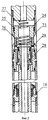
Гидродомкрат иллюстрируется чертежами, представленными на фиг.1-4. На фиг.1 изображен общий вид домкрата, его компоновка; на фиг.2 - схема выпускного клапана в закрытом положении; на фиг.3 - выдвижной толкатель в момент перемещения цанги в рабочее фиксируемое положение; на фиг.4 - выпускной клапан в открытом положении.The hydraulic jack is illustrated by the drawings shown in figures 1-4. Figure 1 shows a General view of the jack, its layout; figure 2 - diagram of the exhaust valve in the closed position; figure 3 - retractable pusher at the time of movement of the collet in a working fixed position; figure 4 - exhaust valve in the open position.
Компоновка гидродомкрата включает следующие, соединенные последовательно, основные элементы (фиг.1): сливной клапан 1, якорь 2 с выдвижными плашками 3, выпускной клапан 4 с узкими продольными прорезями 5 на корпусе, силовые гидроцилиндры 6, граненую штангу 7, установленную в ниппеле 8, нижний переводник 9 с промывочным штуцером 10.The layout of the hydraulic jack includes the following, connected in series, the main elements (figure 1): drain valve 1, anchor 2 with retractable dies 3, exhaust valve 4 with narrow longitudinal slots 5 on the body, power hydraulic cylinders 6, faceted rod 7 installed in the nipple 8 , lower sub 9 with flushing fitting 10.
Силовые гидроцилиндры 6 состоят из нескольких секций, количество которых устанавливается в зависимости от условий эксплуатации гидродомкрата. Каждая секция включает цилиндр 11, пустотелый шток 12 с радиальным отверстием 13, поршень 14 с односторонней манжетой 15 и ниппель 16 с эластичным уплотнением 17. Пустотелый ствол домкрата образуют штоки 12, соединенные поршнями 14, граненая штанга 7 и переводник 9.Power hydraulic cylinders 6 consist of several sections, the number of which is set depending on the operating conditions of the hydraulic jack. Each section includes a cylinder 11, a
Для фиксации ствола домкрата в верхнем положении при транспортировке и спуске в скважину установлены срезные штифты 18. Корпус домкрата образуют: сливной клапан 1, корпусы якоря 2 и выпускного клапана 4, цилиндры 11, соединенные ниппелями 16, ниппель 8 граненой штанги 7 и цилиндр с отверстиями под срезные штифты 18.To fix the barrel of the jack in the upper position during transportation and lowering into the well, shear pins are installed 18. The body of the jack is formed by: drain valve 1, housing of the armature 2 and exhaust valve 4, cylinders 11 connected by
На штангу 7 навинчен переводник 9 для соединения с ловильным инструментом (не показан). В переводнике 9 выполнено седло 19 обратного клапана для посадки шарика 20. Переводник 21 сливного клапана 1 соединен с ловильной колонной 22.An adapter 9 is screwed onto the rod 7 for connection with a fishing tool (not shown). In the sub 9, a non-return valve seat 19 is made for seating the ball 20. The sub 21 of the drain valve 1 is connected to the fishing column 22.
Внутри корпуса 23 выпускного клапана 4 (фиг.2-4) установлен с возможностью осевого перемещения пустотелый поршень 24, имеющей кольцевое 25 и манжетное 26 уплотнения. В полости поршня 24 установлена пружина 27, прижимающая поршень 24 до упора в уступ корпуса 23. На торце ствола домкрата установлен выдвижной толкатель клапана 4, состоящий из втулки 28 и скользящей цанги 29.Inside the
При спуске домкрата в скважину, когда ствол с поршнями 14 зафиксирован в верхнем положении срезными штифтами 18, цанга 29 смещена вниз на втулке 28 до упора в торец ствола (фиг.2), а косые срезы на утолщениях пластин цанги 29 прижаты к конусной поверхности втулки 28.When the jack is lowered into the well, when the barrel with pistons 14 is fixed in the upper position by shear pins 18, the
При перемещении ствола с поршнями 14 в нижнее положение, цанга 29, упираясь в ниппель 16, скользит по втулке 28 вверх (фиг.3), пластины цанги 29 раздвигаются и, затем сходятся над торцом втулки 28, фиксируя цангу 29 в выдвинутом положении (фиг.4). В дальнейшем, в конце каждого хода поршней 14 вверх, выдвинутый толкатель выпускного клапана 4 открывает его, а при смещении ствола домкрата вниз под действием сжатой пружины 27 клапан 4 закрывается.When moving the barrel with pistons 14 to the lower position, the
Домкрат работает следующим образом. При спуске в скважину жидкость через пустотелый ствол поступает в полость домкрата и колонну ловильных труб 22. На любой глубине спуск может быть остановлен, к ловильной колонне 22 присоединена нагнетательная линия и через пустотелый ствол домкрата и штуцер 10, установленный в нижнем переводнике 9, произведена промывка скважины. Следует иметь в виду, что при промывке в домкрате давление значительно превышает давление в скважине. Перепад давления прижимает плашки якоря 3 к обсадной колонне с большим усилием, поэтому перемещать колонну в скважине в процессе промывки запрещается.The jack works as follows. When descending into the well, the fluid through the hollow shaft enters the cavity of the jack and the column of fishing tubes 22. At any depth, the descent can be stopped, the discharge line is connected to the fishing column 22 and through the hollow shaft of the jack and the nozzle 10 installed in the lower sub 9, washing is performed wells. It should be borne in mind that when washing in a jack, the pressure significantly exceeds the pressure in the well. The differential pressure presses the anchor 3 dies to the casing with great effort, therefore it is forbidden to move the column in the well during the flushing process.
При спуске на забой осевая струйная промывка через штуцер 10 должна способствовать очистке головы прихваченного объекта от осевшего песка или шлама, повысить возможность успешного присоединения ловильного инструмента (не показан). После присоединения в ряде случаев целесообразно предпринять попытку вызова циркуляции через каналы прихваченного объекта, что может облегчить ликвидацию прихвата. После завершения промывки производится натяжение инструмента, срезаются штифты 18, инструмент с корпусом домкрата поднимается вверх до упора. Создается усилие в 5-15 т для проверки надежности присоединения ловильного инструмента. В ловильную колонну 22 сбрасывается шарик 20 для посадки в седло 19 обратного клапана. Посадка может быть ускорена восстановлением циркуляции. Рост давления и прекращение циркуляции свидетельствуют о закрытии обратного клапана.When descending to the bottom, axial jet washing through the nozzle 10 should help to clean the head of the stuck object from settled sand or sludge, increase the possibility of successful attachment of a fishing tool (not shown). After joining, in some cases it is advisable to attempt to call circulation through the channels of the tacked object, which can facilitate the elimination of tack. After the flushing is completed, the tool is tensioned, the pins 18 are cut off, the tool with the jack body rises up to the stop. A force of 5-15 tons is created to check the reliability of the attachment of the fishing tool. A ball 20 is dropped into the fishing column 22 for seating in the check valve seat 19. Landing can be accelerated by the restoration of circulation. The increase in pressure and the cessation of circulation indicate the closure of the check valve.
Для ликвидации прихвата давление в нагнетательной линии может повышаться до величины, предусмотренной в паспорте домкрата. При достижении усилия на стволе домкрата, достаточного для преодоления сопротивлений на прихваченном объекте, ствол с извлекаемым инструментом начинает подниматься. Конец хода поршней 24 сопровождается резким падением давления при открытии выпускного клапана 4. Циркуляция прекращается, делается выдержка для выравнивания давления в домкрате и скважине, что необходимо для защиты от износа вооружения плашек 3 якоря 2. Инструмент поднимается на величину хода поршней 14 домкрата, т.е. до появления натяжки. Снова создается давление, процесс повторяется до полной ликвидации прихвата.To eliminate sticking, the pressure in the discharge line may increase to the value provided in the passport of the jack. Upon reaching the effort on the barrel of the jack, sufficient to overcome the resistance on the stuck object, the barrel with the extracted tool begins to rise. The end of the stroke of the
Кроме рассмотренных особенностей, отличающих предлагаемую конструкцию от домкрата типа ГИД, следует отметить два обстоятельства:In addition to the considered features that distinguish the proposed design from a jack of type HID, two circumstances should be noted:
- установка дополнительного цилиндра полностью компенсирует утраченную возможность передачи на прихваченный объект усилия через ловильный инструмент от грузоподъемной установки, т.к. общая нагрузка в обоих случаях лимитируется прочностью ствола домкрата;- the installation of an additional cylinder completely compensates for the lost possibility of transferring force to the tacked object through a fishing tool from a lifting device, because the total load in both cases is limited by the strength of the barrel of the jack;
- предлагаемая конструкция обеспечивает более надежную передачу крутящего момента на ловильный инструмент при его присоединении и отсоединении от прихваченного объекта, т.к. момент от ловильной колонны передается не через штоки домкрата, имеющие минимальную по диаметру резьбу, а по корпусу домкрата.- the proposed design provides a more reliable transmission of torque to the fishing tool when it is attached and disconnected from the stuck object, because the moment from the fishing column is transmitted not through the jack rods having a minimum thread diameter, but along the jack body.
Claims (2)
Priority Applications (1)
| Application Number | Priority Date | Filing Date | Title |
|---|---|---|---|
| RU2005100453/03A RU2282708C1 (en) | 2005-01-11 | 2005-01-11 | Downhole hydraulic jack for releasing of stuck pipes |
Applications Claiming Priority (1)
| Application Number | Priority Date | Filing Date | Title |
|---|---|---|---|
| RU2005100453/03A RU2282708C1 (en) | 2005-01-11 | 2005-01-11 | Downhole hydraulic jack for releasing of stuck pipes |
Publications (2)
| Publication Number | Publication Date |
|---|---|
| RU2005100453A RU2005100453A (en) | 2006-06-20 |
| RU2282708C1 true RU2282708C1 (en) | 2006-08-27 |
Family
ID=36713853
Family Applications (1)
| Application Number | Title | Priority Date | Filing Date |
|---|---|---|---|
| RU2005100453/03A RU2282708C1 (en) | 2005-01-11 | 2005-01-11 | Downhole hydraulic jack for releasing of stuck pipes |
Country Status (1)
| Country | Link |
|---|---|
| RU (1) | RU2282708C1 (en) |
Cited By (18)
| Publication number | Priority date | Publication date | Assignee | Title |
|---|---|---|---|---|
| CN103089229A (en) * | 2012-11-26 | 2013-05-08 | 慕武 | Acid fracturing pipe column ball seat capable of fishing and being used repeatedly |
| CN105003228A (en) * | 2015-08-11 | 2015-10-28 | 荆州市赛瑞能源技术有限公司 | Hydraulically-controlled underground check valve capable of being opened/closed repeatedly |
| US11149510B1 (en) | 2020-06-03 | 2021-10-19 | Saudi Arabian Oil Company | Freeing a stuck pipe from a wellbore |
| US11255130B2 (en) | 2020-07-22 | 2022-02-22 | Saudi Arabian Oil Company | Sensing drill bit wear under downhole conditions |
| US11391104B2 (en) | 2020-06-03 | 2022-07-19 | Saudi Arabian Oil Company | Freeing a stuck pipe from a wellbore |
| US11414984B2 (en) | 2020-05-28 | 2022-08-16 | Saudi Arabian Oil Company | Measuring wellbore cross-sections using downhole caliper tools |
| US11414985B2 (en) | 2020-05-28 | 2022-08-16 | Saudi Arabian Oil Company | Measuring wellbore cross-sections using downhole caliper tools |
| US11434714B2 (en) | 2021-01-04 | 2022-09-06 | Saudi Arabian Oil Company | Adjustable seal for sealing a fluid flow at a wellhead |
| US11506044B2 (en) | 2020-07-23 | 2022-11-22 | Saudi Arabian Oil Company | Automatic analysis of drill string dynamics |
| US11572752B2 (en) | 2021-02-24 | 2023-02-07 | Saudi Arabian Oil Company | Downhole cable deployment |
| US11624265B1 (en) | 2021-11-12 | 2023-04-11 | Saudi Arabian Oil Company | Cutting pipes in wellbores using downhole autonomous jet cutting tools |
| US11631884B2 (en) | 2020-06-02 | 2023-04-18 | Saudi Arabian Oil Company | Electrolyte structure for a high-temperature, high-pressure lithium battery |
| US11697991B2 (en) | 2021-01-13 | 2023-07-11 | Saudi Arabian Oil Company | Rig sensor testing and calibration |
| US11719089B2 (en) | 2020-07-15 | 2023-08-08 | Saudi Arabian Oil Company | Analysis of drilling slurry solids by image processing |
| US11727555B2 (en) | 2021-02-25 | 2023-08-15 | Saudi Arabian Oil Company | Rig power system efficiency optimization through image processing |
| US11846151B2 (en) | 2021-03-09 | 2023-12-19 | Saudi Arabian Oil Company | Repairing a cased wellbore |
| US11867012B2 (en) | 2021-12-06 | 2024-01-09 | Saudi Arabian Oil Company | Gauge cutter and sampler apparatus |
| US11867008B2 (en) | 2020-11-05 | 2024-01-09 | Saudi Arabian Oil Company | System and methods for the measurement of drilling mud flow in real-time |
-
2005
- 2005-01-11 RU RU2005100453/03A patent/RU2282708C1/en not_active IP Right Cessation
Non-Patent Citations (1)
| Title |
|---|
| Композит-каталог нефтегазового оборудования, 1995-1996, М., Топливо и энергетика, т.2, с.640. * |
Cited By (22)
| Publication number | Priority date | Publication date | Assignee | Title |
|---|---|---|---|---|
| CN103089229B (en) * | 2012-11-26 | 2016-08-24 | 慕武 | Can acid fracturing pipe column ball seat capable of fishing and being used repeatedly |
| CN103089229A (en) * | 2012-11-26 | 2013-05-08 | 慕武 | Acid fracturing pipe column ball seat capable of fishing and being used repeatedly |
| CN105003228A (en) * | 2015-08-11 | 2015-10-28 | 荆州市赛瑞能源技术有限公司 | Hydraulically-controlled underground check valve capable of being opened/closed repeatedly |
| CN105003228B (en) * | 2015-08-11 | 2018-04-03 | 荆州市赛瑞能源技术有限公司 | A kind of underground check valve of the repeatable switch of hydraulic control |
| US11414984B2 (en) | 2020-05-28 | 2022-08-16 | Saudi Arabian Oil Company | Measuring wellbore cross-sections using downhole caliper tools |
| US11414985B2 (en) | 2020-05-28 | 2022-08-16 | Saudi Arabian Oil Company | Measuring wellbore cross-sections using downhole caliper tools |
| US11631884B2 (en) | 2020-06-02 | 2023-04-18 | Saudi Arabian Oil Company | Electrolyte structure for a high-temperature, high-pressure lithium battery |
| US11391104B2 (en) | 2020-06-03 | 2022-07-19 | Saudi Arabian Oil Company | Freeing a stuck pipe from a wellbore |
| US11719063B2 (en) | 2020-06-03 | 2023-08-08 | Saudi Arabian Oil Company | Freeing a stuck pipe from a wellbore |
| US11421497B2 (en) | 2020-06-03 | 2022-08-23 | Saudi Arabian Oil Company | Freeing a stuck pipe from a wellbore |
| US11149510B1 (en) | 2020-06-03 | 2021-10-19 | Saudi Arabian Oil Company | Freeing a stuck pipe from a wellbore |
| US11719089B2 (en) | 2020-07-15 | 2023-08-08 | Saudi Arabian Oil Company | Analysis of drilling slurry solids by image processing |
| US11255130B2 (en) | 2020-07-22 | 2022-02-22 | Saudi Arabian Oil Company | Sensing drill bit wear under downhole conditions |
| US11506044B2 (en) | 2020-07-23 | 2022-11-22 | Saudi Arabian Oil Company | Automatic analysis of drill string dynamics |
| US11867008B2 (en) | 2020-11-05 | 2024-01-09 | Saudi Arabian Oil Company | System and methods for the measurement of drilling mud flow in real-time |
| US11434714B2 (en) | 2021-01-04 | 2022-09-06 | Saudi Arabian Oil Company | Adjustable seal for sealing a fluid flow at a wellhead |
| US11697991B2 (en) | 2021-01-13 | 2023-07-11 | Saudi Arabian Oil Company | Rig sensor testing and calibration |
| US11572752B2 (en) | 2021-02-24 | 2023-02-07 | Saudi Arabian Oil Company | Downhole cable deployment |
| US11727555B2 (en) | 2021-02-25 | 2023-08-15 | Saudi Arabian Oil Company | Rig power system efficiency optimization through image processing |
| US11846151B2 (en) | 2021-03-09 | 2023-12-19 | Saudi Arabian Oil Company | Repairing a cased wellbore |
| US11624265B1 (en) | 2021-11-12 | 2023-04-11 | Saudi Arabian Oil Company | Cutting pipes in wellbores using downhole autonomous jet cutting tools |
| US11867012B2 (en) | 2021-12-06 | 2024-01-09 | Saudi Arabian Oil Company | Gauge cutter and sampler apparatus |
Also Published As
| Publication number | Publication date |
|---|---|
| RU2005100453A (en) | 2006-06-20 |
Similar Documents
| Publication | Publication Date | Title |
|---|---|---|
| RU2282708C1 (en) | Downhole hydraulic jack for releasing of stuck pipes | |
| CA2398032C (en) | Open well plunger-actuated gas lift valve and method of use | |
| US4738599A (en) | Well pump | |
| AU730038B2 (en) | Tool and method for removing excess cement from the top of a liner after hanging and cementing thereof | |
| EP0301734B1 (en) | Downhole circulation valve | |
| RU94628U1 (en) | DEVICE FOR OPERATION OF THE LAYER WITH DIFFERENT PERMEABILITY ZONES | |
| RU154511U1 (en) | PACKER DRILLING WITH A LANDING TOOL | |
| CN107893644B (en) | Underground hydraulic control device | |
| RU164723U1 (en) | PACKER DRILLED | |
| RU154295U1 (en) | PACKER DRILLED | |
| CN116816308A (en) | Oil-free pipe paraffin removal lifting device for small-bore shale oil well | |
| CN110617025A (en) | Pumping type casing pipe plugging tool for tubing running without pressure and using method thereof | |
| US4637469A (en) | Apparatus and method of well preparation for chemical treatment of produced fluids | |
| CN113356786B (en) | Bidirectional slip packer using fishing spear to unseal and force releasing | |
| US3497001A (en) | Tubing anchor and drain assembly | |
| RU2371567C1 (en) | Localisation method of leakage areas of production string | |
| RU2311526C2 (en) | Shutoff valve | |
| CN110847846B (en) | Packer for oil field exploitation | |
| US2990883A (en) | Bridge plugs and packers for oil wells | |
| RU67169U1 (en) | DEPTH HYDRAULIC JACK FOR ELIMINATION OF TAKEOFFS WITH TRANSMISSION OF TORQUE AND EMERGENCY CURTAIN | |
| RU2301321C2 (en) | Anchor packer | |
| CN110617034B (en) | Isolation gas lift method of permanent well completion pipe string | |
| CN213511140U (en) | Hard sealing rod type oil well pump and special pipe pump connecting, sealing and fixing device | |
| RU2190080C2 (en) | Downhole hydraulic jack to remedy seizures | |
| CN211448602U (en) | Pumping type casing pipe plugging tool for pressing oil pipe without pressure |
Legal Events
| Date | Code | Title | Description |
|---|---|---|---|
| MM4A | The patent is invalid due to non-payment of fees |
Effective date: 20100112 |