US11652202B2 - Positive electrode for non-aqueous electrolyte secondary battery, and non-aqueous electrolyte secondary battery - Google Patents
Positive electrode for non-aqueous electrolyte secondary battery, and non-aqueous electrolyte secondary battery Download PDFInfo
- Publication number
- US11652202B2 US11652202B2 US16/300,674 US201616300674A US11652202B2 US 11652202 B2 US11652202 B2 US 11652202B2 US 201616300674 A US201616300674 A US 201616300674A US 11652202 B2 US11652202 B2 US 11652202B2
- Authority
- US
- United States
- Prior art keywords
- positive electrode
- active material
- electrode active
- carbon
- battery
- Prior art date
- Legal status (The legal status is an assumption and is not a legal conclusion. Google has not performed a legal analysis and makes no representation as to the accuracy of the status listed.)
- Active
Links
Images


Classifications
-
- H—ELECTRICITY
- H01—ELECTRIC ELEMENTS
- H01M—PROCESSES OR MEANS, e.g. BATTERIES, FOR THE DIRECT CONVERSION OF CHEMICAL ENERGY INTO ELECTRICAL ENERGY
- H01M4/00—Electrodes
- H01M4/02—Electrodes composed of, or comprising, active material
- H01M4/36—Selection of substances as active materials, active masses, active liquids
- H01M4/362—Composites
- H01M4/366—Composites as layered products
-
- H—ELECTRICITY
- H01—ELECTRIC ELEMENTS
- H01M—PROCESSES OR MEANS, e.g. BATTERIES, FOR THE DIRECT CONVERSION OF CHEMICAL ENERGY INTO ELECTRICAL ENERGY
- H01M10/00—Secondary cells; Manufacture thereof
- H01M10/05—Accumulators with non-aqueous electrolyte
- H01M10/052—Li-accumulators
- H01M10/0525—Rocking-chair batteries, i.e. batteries with lithium insertion or intercalation in both electrodes; Lithium-ion batteries
-
- H—ELECTRICITY
- H01—ELECTRIC ELEMENTS
- H01M—PROCESSES OR MEANS, e.g. BATTERIES, FOR THE DIRECT CONVERSION OF CHEMICAL ENERGY INTO ELECTRICAL ENERGY
- H01M10/00—Secondary cells; Manufacture thereof
- H01M10/05—Accumulators with non-aqueous electrolyte
- H01M10/056—Accumulators with non-aqueous electrolyte characterised by the materials used as electrolytes, e.g. mixed inorganic/organic electrolytes
- H01M10/0561—Accumulators with non-aqueous electrolyte characterised by the materials used as electrolytes, e.g. mixed inorganic/organic electrolytes the electrolyte being constituted of inorganic materials only
- H01M10/0563—Liquid materials, e.g. for Li-SOCl2 cells
-
- H—ELECTRICITY
- H01—ELECTRIC ELEMENTS
- H01M—PROCESSES OR MEANS, e.g. BATTERIES, FOR THE DIRECT CONVERSION OF CHEMICAL ENERGY INTO ELECTRICAL ENERGY
- H01M10/00—Secondary cells; Manufacture thereof
- H01M10/05—Accumulators with non-aqueous electrolyte
- H01M10/056—Accumulators with non-aqueous electrolyte characterised by the materials used as electrolytes, e.g. mixed inorganic/organic electrolytes
- H01M10/0564—Accumulators with non-aqueous electrolyte characterised by the materials used as electrolytes, e.g. mixed inorganic/organic electrolytes the electrolyte being constituted of organic materials only
- H01M10/0566—Liquid materials
-
- H—ELECTRICITY
- H01—ELECTRIC ELEMENTS
- H01M—PROCESSES OR MEANS, e.g. BATTERIES, FOR THE DIRECT CONVERSION OF CHEMICAL ENERGY INTO ELECTRICAL ENERGY
- H01M10/00—Secondary cells; Manufacture thereof
- H01M10/42—Methods or arrangements for servicing or maintenance of secondary cells or secondary half-cells
- H01M10/4235—Safety or regulating additives or arrangements in electrodes, separators or electrolyte
-
- H—ELECTRICITY
- H01—ELECTRIC ELEMENTS
- H01M—PROCESSES OR MEANS, e.g. BATTERIES, FOR THE DIRECT CONVERSION OF CHEMICAL ENERGY INTO ELECTRICAL ENERGY
- H01M4/00—Electrodes
- H01M4/02—Electrodes composed of, or comprising, active material
- H01M4/13—Electrodes for accumulators with non-aqueous electrolyte, e.g. for lithium-accumulators; Processes of manufacture thereof
- H01M4/133—Electrodes based on carbonaceous material, e.g. graphite-intercalation compounds or CFx
-
- H—ELECTRICITY
- H01—ELECTRIC ELEMENTS
- H01M—PROCESSES OR MEANS, e.g. BATTERIES, FOR THE DIRECT CONVERSION OF CHEMICAL ENERGY INTO ELECTRICAL ENERGY
- H01M4/00—Electrodes
- H01M4/02—Electrodes composed of, or comprising, active material
- H01M4/13—Electrodes for accumulators with non-aqueous electrolyte, e.g. for lithium-accumulators; Processes of manufacture thereof
- H01M4/136—Electrodes based on inorganic compounds other than oxides or hydroxides, e.g. sulfides, selenides, tellurides, halogenides or LiCoFy
-
- H—ELECTRICITY
- H01—ELECTRIC ELEMENTS
- H01M—PROCESSES OR MEANS, e.g. BATTERIES, FOR THE DIRECT CONVERSION OF CHEMICAL ENERGY INTO ELECTRICAL ENERGY
- H01M4/00—Electrodes
- H01M4/02—Electrodes composed of, or comprising, active material
- H01M4/36—Selection of substances as active materials, active masses, active liquids
- H01M4/362—Composites
-
- H—ELECTRICITY
- H01—ELECTRIC ELEMENTS
- H01M—PROCESSES OR MEANS, e.g. BATTERIES, FOR THE DIRECT CONVERSION OF CHEMICAL ENERGY INTO ELECTRICAL ENERGY
- H01M4/00—Electrodes
- H01M4/02—Electrodes composed of, or comprising, active material
- H01M4/36—Selection of substances as active materials, active masses, active liquids
- H01M4/48—Selection of substances as active materials, active masses, active liquids of inorganic oxides or hydroxides
- H01M4/52—Selection of substances as active materials, active masses, active liquids of inorganic oxides or hydroxides of nickel, cobalt or iron
- H01M4/523—Selection of substances as active materials, active masses, active liquids of inorganic oxides or hydroxides of nickel, cobalt or iron for non-aqueous cells
-
- H—ELECTRICITY
- H01—ELECTRIC ELEMENTS
- H01M—PROCESSES OR MEANS, e.g. BATTERIES, FOR THE DIRECT CONVERSION OF CHEMICAL ENERGY INTO ELECTRICAL ENERGY
- H01M4/00—Electrodes
- H01M4/02—Electrodes composed of, or comprising, active material
- H01M4/36—Selection of substances as active materials, active masses, active liquids
- H01M4/58—Selection of substances as active materials, active masses, active liquids of inorganic compounds other than oxides or hydroxides, e.g. sulfides, selenides, tellurides, halogenides or LiCoFy; of polyanionic structures, e.g. phosphates, silicates or borates
- H01M4/5825—Oxygenated metallic salts or polyanionic structures, e.g. borates, phosphates, silicates, olivines
-
- H—ELECTRICITY
- H01—ELECTRIC ELEMENTS
- H01M—PROCESSES OR MEANS, e.g. BATTERIES, FOR THE DIRECT CONVERSION OF CHEMICAL ENERGY INTO ELECTRICAL ENERGY
- H01M4/00—Electrodes
- H01M4/02—Electrodes composed of, or comprising, active material
- H01M4/36—Selection of substances as active materials, active masses, active liquids
- H01M4/58—Selection of substances as active materials, active masses, active liquids of inorganic compounds other than oxides or hydroxides, e.g. sulfides, selenides, tellurides, halogenides or LiCoFy; of polyanionic structures, e.g. phosphates, silicates or borates
- H01M4/583—Carbonaceous material, e.g. graphite-intercalation compounds or CFx
-
- H—ELECTRICITY
- H01—ELECTRIC ELEMENTS
- H01M—PROCESSES OR MEANS, e.g. BATTERIES, FOR THE DIRECT CONVERSION OF CHEMICAL ENERGY INTO ELECTRICAL ENERGY
- H01M4/00—Electrodes
- H01M4/02—Electrodes composed of, or comprising, active material
- H01M4/62—Selection of inactive substances as ingredients for active masses, e.g. binders, fillers
- H01M4/624—Electric conductive fillers
- H01M4/625—Carbon or graphite
-
- H—ELECTRICITY
- H01—ELECTRIC ELEMENTS
- H01M—PROCESSES OR MEANS, e.g. BATTERIES, FOR THE DIRECT CONVERSION OF CHEMICAL ENERGY INTO ELECTRICAL ENERGY
- H01M4/00—Electrodes
- H01M4/02—Electrodes composed of, or comprising, active material
- H01M2004/021—Physical characteristics, e.g. porosity, surface area
-
- H—ELECTRICITY
- H01—ELECTRIC ELEMENTS
- H01M—PROCESSES OR MEANS, e.g. BATTERIES, FOR THE DIRECT CONVERSION OF CHEMICAL ENERGY INTO ELECTRICAL ENERGY
- H01M4/00—Electrodes
- H01M4/02—Electrodes composed of, or comprising, active material
- H01M2004/026—Electrodes composed of, or comprising, active material characterised by the polarity
- H01M2004/028—Positive electrodes
-
- H—ELECTRICITY
- H01—ELECTRIC ELEMENTS
- H01M—PROCESSES OR MEANS, e.g. BATTERIES, FOR THE DIRECT CONVERSION OF CHEMICAL ENERGY INTO ELECTRICAL ENERGY
- H01M2300/00—Electrolytes
- H01M2300/0017—Non-aqueous electrolytes
- H01M2300/002—Inorganic electrolyte
-
- Y—GENERAL TAGGING OF NEW TECHNOLOGICAL DEVELOPMENTS; GENERAL TAGGING OF CROSS-SECTIONAL TECHNOLOGIES SPANNING OVER SEVERAL SECTIONS OF THE IPC; TECHNICAL SUBJECTS COVERED BY FORMER USPC CROSS-REFERENCE ART COLLECTIONS [XRACs] AND DIGESTS
- Y02—TECHNOLOGIES OR APPLICATIONS FOR MITIGATION OR ADAPTATION AGAINST CLIMATE CHANGE
- Y02E—REDUCTION OF GREENHOUSE GAS [GHG] EMISSIONS, RELATED TO ENERGY GENERATION, TRANSMISSION OR DISTRIBUTION
- Y02E60/00—Enabling technologies; Technologies with a potential or indirect contribution to GHG emissions mitigation
- Y02E60/10—Energy storage using batteries
Definitions
- the present invention relates to a positive electrode for non-aqueous electrolyte secondary battery and to a non-aqueous electrolyte secondary battery.
- Non-aqueous electrolyte type lithium ion secondary batteries have been recently put to practical use as small-sized, light-weight, and chargeable/dischargeable batteries having high capacity.
- non-aqueous electrolyte solutions each obtained by dissolving a lithium salt in a non-aqueous solvent as an electrolyte solution are usually used.
- batteries used heretofore include a safety mechanism such as a safety valve and separator.
- These batteries have a structure in which a safety valve is cleft to release an increased internal pressure of the battery and to thereby prevent the battery from being broken when the battery is put in an abnormal state, for example, in a case where the battery generates heat caused by, for example, overcharge.
- these batteries have a structure in which pores formed in a separator are blocked (shutdown) to shut paths of conductor ions in the battery when battery temperature reaches about 120° C. in order to prevent further proceeding of reaction when the battery is put in an abnormal state, for example, in a case where the battery generated heat caused by, for example, overcharge.
- a positive electrode active material which includes a carbonaceous coating film with which surfaces of olivine-based inorganic particles are coated (see, for example, Patent Document 1).
- the positive electrode active material layer is usually formed by blending a positive electrode active material, a conductive auxiliary agent such as acetylene black, and a binder. Accordingly, the positive electrode active material layer contains a carbon material as the carbonaceous coating film or conductive auxiliary agent.
- the carbon material may be generally classified into a carbon material having a certain crystal structure such as graphite and fullerene, and amorphous carbon (microcrystalline carbon). Also, the amorphous carbon may be generally classified into graphitizable carbon (soft carbon) and non-graphitizable carbon (hard carbon).
- the graphitizable carbon is a carbon material that is easily made into graphite by high-temperature treatment.
- the graphitizable carbon is generally amorphous carbon that is an aggregate of a plurality of basic structure units (BSU) and has an oriented structure in which the plurality of basic structure units are oriented.
- the basic structure unit is a structure unit in which a plurality of carbon hexagonal network planes are laminated and microscopically has a structure analogous to graphite.
- carbon materials obtained by heat-treatment of pitches, graphitizable cokes, and the like are generally categorized as the graphitizable carbon (see, for example, Patent Document 2).
- the non-graphitizable carbon is a carbon material of which progress of graphitization is slow in high-temperature treatment.
- the non-graphitizable carbon is generally amorphous carbon in which a plurality of basic structure units are assembled and has an unoriented structure in which the plurality of basic structure units are not oriented.
- carbon materials obtained by heat-treatment of thermosetting resins, carbon black, non-graphitizable cokes, carbon materials obtained by heat-treatment of vegetable type raw materials, and the like are categorized as the non-graphitizable carbon (see, for example, Patent Document 2).
- Patent Document 1 JP-A No. 2015-65134
- Patent Document 2 JP-A No. 2015-070032
- a safety mechanism like those having conventional structures causes an electrolyte solution inside a battery to be boiled by exothermal influence exerted when a battery is overcharged, so that a battery safety valve is opened.
- the safety valve When the safety valve is opened, the electrolyte solution in the battery blows around the battery with a possibility of exerting adverse influence on peripheral devices.
- the present invention has been made and provides a positive electrode for non-aqueous electrolyte secondary battery having a novel overcharge protective function.
- the present invention provides a positive electrode for non-aqueous electrolyte secondary battery, the positive electrode including a positive electrode active material layer containing a plurality of positive electrode active material particles, wherein the positive electrode active material layer includes: a carbonaceous coating film formed on a surface of each of the positive electrode active material particles; and 0% by weight or more and 20% by weight or less of a conductive auxiliary agent disposed between the plurality of positive electrode active material particles, and at least one of the carbonaceous coating film and the conductive auxiliary agent is graphitizable carbon.
- a positive electrode for non-aqueous electrolyte secondary battery according to the present invention includes a positive electrode active material layer containing a plurality of positive electrode active material particles. Therefore, an electrode reaction (for example, intercalation of ions into a positive electrode active material and deintercalation of ions from the positive electrode active material) can be promoted in the positive electrode active material particles in association with charging/discharging, and therefore a non-aqueous electrolyte secondary battery can be charged/discharged.
- an electrode reaction for example, intercalation of ions into a positive electrode active material and deintercalation of ions from the positive electrode active material
- the positive electrode active material layer includes a carbonaceous coating film formed on a surface of each of the positive electrode active material particles and 0% by weight or more and 20% by weight or less of a conductive auxiliary agent disposed between the plurality of positive electrode active material particles. Therefore, the carbonaceous coating film or conductive auxiliary agent can be served as an electronic conduction path, enabling rapid electron transfer associated with the electrode reaction. This can improve battery characteristics. Also, a material having a relatively low conductivity can be used as the positive electrode active material particle.
- At least one of the carbonaceous coating film and the conductive auxiliary agent is graphitizable carbon (soft carbon). This ensures that the carbonaceous coating film or conductive auxiliary agent which serves as the electronic conduction path can be made to have high resistance when the non-aqueous electrolyte secondary battery is put into an overcharged state. It has been clarified by an experiment made by inventors of the present invention that the graphitizable carbon has a high conductivity when a battery is charged/discharged and is made to have high resistance when the battery is put into an overcharged state. Though this reason has not been clarified, it is inferred that the graphitizable carbon is electrochemically degraded or reacted and resultantly denatured by a positive electrode potential raised by overcharging.
- the carbonaceous coating film and the conductive auxiliary agent which serve as electronic conduction paths can be made to have high resistance when a non-aqueous electrolyte secondary battery is put into an overcharged state, making it possible to rapidly reduce charge current flowing in the battery in an overcharged state.
- This can reduce exothermic heat caused by electrochemical reaction of an electrolyte solution and exothermic heat caused by flow of current in the carbonaceous coating film or conductive auxiliary agent, and therefore rise in temperature of the battery and hence boiling of the electrolyte solution can be restrained.
- rise in internal pressure caused by overcharge in the battery can be restrained, ensuring that the battery can be prevented from exploding.
- a positive electrode of the present invention if a positive electrode of the present invention is used, a battery with a positive electrode active material layer having a safety improving mechanism can be manufactured.
- a battery can be manufactured using a separator with no shutdown mechanism, heat resistance of the battery can be improved. Also, a protective circuit can be simplified. Moreover, a safety of a large-capacity battery can be improved.
- FIG. 1 ( a ) is a schematic plan view of a positive electrode for non-aqueous electrolyte secondary battery in an embodiment of the present invention and FIGS. 1 ( b ) and 1 ( c ) are schematic sectional views of the positive electrode along a dotted line A-A of FIG. 1 ( a ) .
- FIG. 2 is an enlarged sectional view of a positive electrode active material layer contained in the positive electrode for non-aqueous electrolyte secondary battery in an embodiment of the present invention.
- FIG. 3 is an enlarged sectional view of the positive electrode active material layer contained in the positive electrode for non-aqueous electrolyte secondary battery in an embodiment of the present invention.
- FIG. 4 is a schematic sectional view of the non-aqueous electrolyte secondary battery in an embodiment of the present invention.
- FIG. 5 ( a ) is a schematic plan view of a negative electrode contained in the non-aqueous electrolyte secondary battery in an embodiment of the present invention and FIG. 5 ( b ) is a schematic sectional view of the negative electrode along a dotted line B-B of FIG. 5 ( a ) .
- FIG. 6 is a schematic structural view of a power generation element contained in the non-aqueous electrolyte secondary battery in an embodiment of the present invention.
- FIG. 7 ( a ) is an explanatory view of a microstructure of graphitizable carbon and FIG. 7 ( b ) is an explanatory view of a microstructure of non-graphitizable carbon.
- FIGS. 8 ( a ) to 8 ( c ) are graphs showing results of an overcharge test (1).
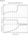
- FIGS. 9 ( a ) to 9 ( c ) are graphs showing results of an overcharge test (1).
- FIGS. 10 ( a ) and 10 ( b ) are TEM photographs of a positive electrode active material (1).
- FIGS. 11 ( a ) and 11 ( b ) are TEM photographs of a positive electrode active material (3).
- FIG. 12 is a schematic sectional view of a beaker cell.
- FIG. 13 is a graph showing results of a voltage application experiment.
- FIG. 14 is a graph showing results of an overcharge test (2).
- a positive electrode for non-aqueous electrolyte secondary battery includes a positive electrode active material layer containing a plurality of positive electrode active material particles, in which the positive electrode active material layer includes a carbonaceous coating film formed on a surface of each of the positive electrode active material particles and 0% by weight or more and 20% by weight or less of a conductive auxiliary agent disposed between the plurality of positive electrode active material particles, and at least one of the carbonaceous coating film and the conductive auxiliary agent is graphitizable carbon.
- the carbonaceous coating film and conductive auxiliary agent included in the positive electrode of the present invention are preferably amorphous carbon constituted of an aggregate of a plurality of basic structure units each having a structure in which a plurality of carbon hexagonal network planes are laminated and preferably has an oriented structure in which the plurality of basic structure units are oriented. This ensures that the carbonaceous coating film and the conductive auxiliary agent can be made to have high resistance when a non-aqueous electrolyte secondary battery is put into an overcharged state with a result that exothermic heat of the positive electrode active material layer can be restrained.
- the carbonaceous coating film and the conductive auxiliary agent included in the positive electrode of the present invention are preferably those (pitch type carbon materials) obtained by baking pitch type materials. This ensures that the carbonaceous coating film or conductive auxiliary agent can be made to have high resistance when the non-aqueous electrolyte secondary battery is put into an overcharged state.
- 90% or more of a total amount of the carbonaceous coating film and conductive auxiliary agent included in the positive electrode active material layer of the positive electrode of the present invention is preferably graphitizable carbon. This ensures that the carbonaceous coating film and the conductive auxiliary agent can be made to have high resistance when the non-aqueous electrolyte secondary battery is put into an overcharged state.
- the carbonaceous coating film and the conductive auxiliary agent included in the positive electrode of the present invention preferably have a material density of 1.8 g/cm 3 or more and 2.1 g/cm 3 or less. This ensures that the carbonaceous coating film and the conductive auxiliary agent can be made to have high resistance when the non-aqueous electrolyte secondary battery is put into an overcharged state.
- the positive electrode active material particles contained in the positive electrode active material layer of the positive electrode of the present invention is preferably olivine type compound particles or NASICON type compound particles. This ensures that heat stability of a positive electrode active material can be improved and therefore, safety of the non-aqueous electrolyte secondary battery can be improved.
- the positive electrode of the present invention preferably includes a positive electrode current collector sheet and the positive electrode active material layer is preferably formed on the positive electrode current collector sheet. This ensures that a conductive distance between the positive electrode current collector sheet and the positive electrode active material can be shortened, enabling rapid electron transfer associated with an electrode reaction.
- the positive electrode active material layer included in the positive electrode of the present invention preferably contains substantially no non-graphitizable carbon (hard carbon) and substantially no graphite. This ensures that the positive electrode active material layer can be made to have high resistance when the non-aqueous electrolyte secondary battery is put into an overcharged state with a result that exothermic heat of the battery put into an overcharged state can be restrained.
- the present invention also provides a non-aqueous electrolyte secondary battery including the positive electrode of the present invention, a negative electrode having a negative electrode active material, a separator sandwiched between the positive electrode and the negative electrode, a non-aqueous electrolyte, and a battery case in which the positive electrode, the negative electrode, the separator, and the non-aqueous electrolyte are accommodated.
- the positive electrode active material layer can be made to have high resistance when the non-aqueous electrolyte secondary battery is put into an overcharged state with a result that rise in temperature of the battery can be restrained. Accordingly, rise in internal pressure of the battery caused by overcharge can be restrained, ensuring that the battery can be prevented from exploding.
- the negative electrode active material is preferably a carbon material
- the non-aqueous electrolyte is preferably an electrolyte solution in which a lithium salt is dissolved in a non-aqueous solvent
- the carbonaceous coating film and the conductive auxiliary agent are preferably graphitizable carbon which is electrochemically degraded or reacted into highly resistant carbon in an overcharged state.
- FIG. 1 ( a ) is a schematic plan view of a positive electrode for non-aqueous electrolyte secondary battery in this embodiment and FIGS. 1 ( b ) and 1 ( c ) are schematic sectional views of the positive electrode along a dotted line A-A of FIG. 1 ( a ) .
- FIGS. 2 and 3 are enlarged sectional views of a positive electrode active material layer included in the positive electrode for non-aqueous electrolyte secondary battery in this embodiment.
- FIG. 4 is a schematic sectional view of the non-aqueous electrolyte secondary battery in this embodiment.
- FIG. 5 ( a ) is a schematic sectional view of a negative electrode contained in the non-aqueous electrolyte secondary battery in this embodiment and FIG.
- FIG. 5 ( b ) is a schematic sectional view of the negative electrode along a line B-B of FIG. 5 ( a ) .
- FIG. 6 is a schematic structural view of a power generation element contained in the non-aqueous electrolyte secondary battery in this embodiment.
- a positive electrode 5 for non-aqueous electrolyte secondary battery in this embodiment includes a positive electrode active material layer 1 containing a plurality of positive electrode active material particles 6 , in which the positive electrode active material layer 1 includes a carbonaceous coating film 8 formed on a surface of each of the positive electrode particles 6 and 0% by weight or more and 20% by weight or less of a conductive auxiliary agent 7 disposed between the plurality of positive electrode active material particles, and at least one of the carbonaceous coating film 8 and the conductive auxiliary agent 7 is graphitizable carbon.
- a non-aqueous electrolyte secondary battery 30 of this embodiment includes the positive electrode 5 of this embodiment, a negative electrode 32 having a negative electrode active material, a separator 34 sandwiched between the positive electrode 5 and the negative electrode 32 , a non-aqueous electrolyte 15 , and a battery case 11 in which the positive electrode 5 , the negative electrode 32 , separator 34 , and the non-aqueous electrolyte 15 are accommodated.
- the positive electrode 5 for non-aqueous electrolyte secondary battery and the non-aqueous electrolyte secondary battery 30 of this embodiment will be described hereinbelow.
- the positive electrode 5 for non-aqueous electrolyte secondary battery is a positive electrode constituting the non-aqueous electrolyte secondary battery 30 or a positive electrode used for production of the non-aqueous electrolyte secondary battery 30 .
- the positive electrode 5 for non-aqueous electrolyte secondary battery includes the positive electrode active material layer 1 containing a plurality of positive electrode active material particles 6 .
- the positive electrode 5 may also include a positive electrode current collector sheet 3 and the positive electrode active material layer 1 may be formed on the positive electrode current collector sheet 3 .
- the positive electrode 5 may have such a structure as illustrated in, for example, FIGS. 1 ( a ) and 1 ( b ) .
- the positive electrode current collector sheet 3 may be formed of, for example, a metal foil such as an aluminum foil.
- the positive electrode 5 may also include a base layer 2 between the positive electrode current collector sheet 3 and the positive electrode active material layer 1 .
- the base layer 2 may be formed as shown in FIG. 1 ( c ) .
- the positive electrode active material layer 1 may be a porous layer containing the positive electrode active material particle 6 and a binder.
- the positive electrode active material layer 1 includes at least one of the carbonaceous coating film 8 formed on the surface of the positive electrode active material particle 6 and conductive auxiliary agent 7 disposed between the plurality of positive electrode active material particles 6 .
- the carbonaceous coating film 8 and the conductive auxiliary agent 7 are graphitizable carbon (soft carbon).
- the positive electrode active material layer 1 may have both of the carbonaceous coating film 8 formed on the surface of the positive electrode active material particle 6 and conductive auxiliary agent 7 disposed between the plurality of positive electrode active material particles 6 .
- the carbonaceous coating film 8 and conductive auxiliary agent 7 are both graphitizable carbon.
- the positive electrode active material layer 1 may have such a microstructure as shown in FIG. 2 .
- the positive electrode active material layer 1 as mentioned above may be formed by blending positive electrode active material powder with the carbonaceous coating film 8 formed thereon, the conductive auxiliary agent 7 and a binder to prepare a paste and by applying this paste to the surface of the positive electrode current collector sheet 3 .
- the positive electrode active material layer 1 may contain 0% by weight or more and 20% by weight or less of conductive auxiliary agent.
- the conductive auxiliary agent is expected to have an effect on improvement in output. However, if an amount of the conductive auxiliary agent is excessive, a capacity per volume of the electrode is reduced and therefore the amount of the conductive auxiliary agent is preferably 20% by weight or less.
- the carbonaceous coating film 8 can be formed, for example, by forming a coating layer of an organic compound on the surface of the positive electrode active material particle 6 and by heat-treating this coating layer in a nonoxidizing atmosphere to carbonize the layer.
- the above organic compound may be petroleum pitch or coal pitch. This allows the carbonaceous coating film 8 to be a pitch type carbon material that is graphitizable carbon. Also, the aforementioned heat treatment may be performed at, for example, 500° C. or higher and 1000° C. or lower.
- cokes-based soft carbon that is graphitizable carbon may be used as the conductive auxiliary agent 7 .
- the positive electrode active material layer 1 includes the carbonaceous coating film 8 formed on the surface of the positive electrode active material particle 6 and may include substantially no conductive auxiliary agent 7 .
- the carbonaceous coating film 8 is graphitizable carbon.
- the positive electrode active material layer 1 may have a microstructure as shown in FIG. 3 .
- the positive electrode active material layer 1 may be formed, for example, by blending positive electrode active material powder with the carbonaceous coating film 8 formed thereon and a binder to prepare a paste and by applying the paste to the surface of the positive electrode current collector sheet 3 .
- the positive electrode active material layer 1 has such a structure as mentioned above, the positive electrode active material layer 1 can be made to have high resistance when the non-aqueous electrolyte secondary battery 30 is put into an overcharged state and therefore, charge current flowing in the battery 30 put into an overcharged state can be rapidly reduced.
- This can reduce exothermic heat caused by an electrochemical reaction of an electrolyte solution 15 and exothermic heat caused by current flow in the carbonaceous coating film 8 or conductive auxiliary agent 7 , and therefore the rise in the temperature of the battery 30 and hence boiling of the electrolyte solution 15 can be restrained. This results in that the rise in internal pressure caused by overcharge in the battery 30 can be restrained, ensuring that the battery 30 can be prevented from exploding.
- the graphitizable carbon (soft carbon) is a carbon material that is easily converted into graphite by high-temperature treatment.
- the graphitizable carbon is amorphous carbon that is an aggregate of a plurality of basic structure units 10 (BSU) as shown, for example, by a microstructure illustrated in FIG. 7 ( a ) and has an oriented structure in which the plurality of basic structure units 10 are oriented.
- the basic structure unit 10 is a structural unit in which a plurality of carbon hexagonal network planes 4 are laminated and microscopically has a structure analogous to graphite.
- the basic structure unit 10 may be a crystallite.
- 90% or more of a total amount of the carbonaceous coating film 8 and the conductive auxiliary agent 7 included in the positive electrode active material layer 1 may be graphitizable carbon. This can be checked by confirming whether 90% or more of the total amount of the carbonaceous coating film 8 and the conductive auxiliary agent 7 included in a transmission electron microphotograph of the positive electrode active material layer 1 is graphitizable carbon or not. Also, this can be confirmed by an X-ray diffraction measurement.
- carbon materials obtained by heat-treating pitches such as petroleum pitch and coal pitch and graphitizable cokes are categorized as graphitizable carbon. It is therefore possible to confirm whether or not the carbonaceous coating film 8 and the conductive auxiliary agent 7 contained in the positive electrode active material layer 1 are graphitizable carbon by investigating a raw material and heat-treating temperature of the carbonaceous coating film 8 and the conductive auxiliary agent 7 .
- the carbonaceous coating film 8 and the conductive auxiliary agent 7 may be graphitizable carbon having a material density of 1.8 g/cm 3 or more and 2.1 g/cm 3 or less. Because, generally, graphitizable carbon has a larger material density than non-graphitizable carbon, it is therefore possible to confirm whether the carbonaceous coating film 8 and the conductive auxiliary agent 7 are graphitizable carbon or not by investigating the material densities of the carbonaceous coating film 8 and conductive auxiliary agent 7 .
- the base layer 2 may be a carbon layer containing graphitizable carbon. This makes the carbon layer have a high conductivity, enabling rapid electron transfer associated with an electrode reaction (intercalation of ions into a positive electrode active material and deintercalation of ions from the positive electrode active material) in the positive electrode active material particles 6 . Also, the base layer 2 can be made to have high resistance when the non-aqueous electrolyte secondary battery 30 is put into an overcharged state, which makes it possible to restrain large current from flowing between the positive electrode current collector sheet 3 and the positive electrode active material layer 1 .
- the base layer 2 may be a porous layer containing graphitizable carbon particles and a binder.
- the base layer 2 may be formed by blending graphitizable carbon powder and a binder to prepare a paste and by applying this paste to a surface of the positive electrode current collector sheet 3 .
- the positive electrode active material layer 1 may be formed on the base layer 2 .
- the non-graphitizable carbon (hard carbon) is a carbon material slow in progress of graphitization in high-temperature treatment.
- the non-graphitizable carbon is amorphous carbon which has a microstructure as shown in FIG. 7 ( b ) and an aggregate of a plurality of basic structure units 10 , and it has a non-oriented structure in which a plurality of basic structure units 10 are not oriented.
- carbon materials obtained by heat-treatment of thermosetting resins, carbon black, non-graphitizable cokes, carbon materials obtained by heat-treatment of vegetable type raw materials, and the like are categorized as the non-graphitizable carbon.
- the positive electrode material particles 6 may be particles of a substance (olivine type compound) having an olivine type crystal structure.
- olivine type compound examples include LiFePO 4 and Li x M y PO 4 (where, 0.05 ⁇ x ⁇ 1.2, 0 ⁇ y ⁇ 1, and M is at least one or more of Fe, Mn, Cr, Co, Cu, Ni, V, Mo, Ti, Zn, Al, Ga, Mg, B, and Nb).
- the positive electrode active material particles 6 may be particles of a NASICON type compound represented by Y x M 2 (PO 4 ) 3 .
- the NASICON type compound has a rhombohedral structure and examples of the NASICON type compound include Li 3+x Fe 2 (PO 4 ) 3 , Li 2+x FeTi(PO 4 ) 3 , Li x TiNb(PO 4 ) 3 , and Li 1+x FeNb(PO 4 ) 3 .
- the positive electrode active material particles 6 may be particles of lithium transition metal composite oxide (for example, a layered type and spinel) capable of insertion and extraction of lithium ions reversibly.
- lithium transition metal composite oxide for example, a layered type and spinel
- the positive electrode active material layer 1 may include either only one type or plural types of the aforementioned positive electrode active material particle 6 .
- the positive electrode active material particles 6 may be, as particles of sodium transition metal composite oxide, particles of oxides represented by Na b M 2 c Si 12 O 30 such as Na 6 Fe 2 Si 12 O 30 and Na 2 Fe 5 Si 12 O 30 (M 2 is one or more types of transition metal element, 2 ⁇ b ⁇ 6, 2 ⁇ c ⁇ 5); particles of oxides represented by Na d M 3 e Si 6 O 18 such as Na 2 Fe 2 Si 6 O 18 and Na 2 MnFeSi 6 O 18 (M 3 is one or more types of transition metal element, 3 ⁇ d ⁇ 6, 1 ⁇ e ⁇ 2); particles of oxides represented by Na f M 4 g Si 2 O 6 represented by Na 2 FeSiO 6 (M 4 is one or more types of element selected from the group consisting of transition metal elements, Mg, and Al, 1 ⁇ f ⁇ 2, 1 ⁇ g ⁇ 2); particles of phosphates such as NaFePO 4 and Na 3 Fe 2 (PO 4 ) 3 ; particles of borates such as NaFeBO 4 and Na 3 Fe 2 (BO 4 )
- the positive electrode active material layer 1 may contain either only one type or plural types as the aforementioned positive electrode active material particles 6 .
- binder contained in the positive electrode active material layer 1 examples include polyvinylidene fluoride (PVdF), polytetrafluoroethylene (PTFE), styrene-butadiene copolymer (SBR), acrylonitrile rubber, and acrylonitrile rubber-PTFE mixture.
- PVdF polyvinylidene fluoride
- PTFE polytetrafluoroethylene
- SBR styrene-butadiene copolymer
- acrylonitrile rubber examples include acrylonitrile rubber-PTFE mixture.
- the non-aqueous electrolyte secondary battery 30 includes the aforementioned positive electrode 5 , a negative electrode 32 , a separator 34 sandwiched between the positive electrode 5 and negative electrode 32 , a non-aqueous electrolyte 15 , and a battery case 11 in which the positive electrode 5 , the negative electrode 32 , the separator 34 , and the non-aqueous electrolyte 15 are accommodated.
- the non-aqueous electrolyte secondary battery 30 is, for example, a lithium ion secondary battery or sodium ion secondary battery.
- the non-aqueous electrolyte secondary battery 30 includes the positive electrode 5 for non-aqueous electrolyte secondary battery. Because the details of the positive electrode 5 for non-aqueous electrolyte secondary battery has been explained above, the explanations of the positive electrode 5 are omitted here. It is noted that the positive electrode 5 can constitute a power generation element 22 as shown in FIG. 6 together with the negative electrode 32 and the separator 34 .
- the negative electrode 32 has a porous negative electrode active material layer 36 containing a negative electrode active material. Also, the negative electrode 32 may include a negative electrode current collector sheet 38 .
- the negative electrode active material layer 36 may contain a negative electrode active material, a conductive agent, a binder, and the like.
- the negative electrode active material examples include graphite, partially graphitized carbon, hard carbon, soft carbon, LiTiO 4 , Sn, and Si. Also, the negative electrode active material layer 36 may contain either only one type or plural types of the aforementioned negative electrode active material.
- the negative electrode active material layer 36 may be formed on the negative electrode current collector sheet 38 .
- the negative electrode active material layer 36 may be formed on each main surface of the negative electrode current collector sheet 38 as shown by the negative electrode 32 illustrated in FIGS. 5 ( a ) and 5 ( b ) .
- the separator 34 has a sheet-like form and is disposed between the positive electrode 5 and the negative electrode 32 . Also, the separator 34 can constitute a power generation element 22 as shown in FIG. 6 together with the positive electrode 5 and the negative electrode 32 . The installation of the separator 34 can prevent short-circuit current from flowing between the positive electrode 5 and the negative electrode 32 .
- the separator 34 may be formed from, for example, a polyolefin microporous film, cellulose sheet, or aramid sheet.
- the battery case 11 is a container to accommodate the positive electrode 5 , the negative electrode 32 , the separator 34 , and the non-aqueous electrolyte 15 . Also, the battery case 11 may have an opening covered by a lid member 12 . The power generation element 22 can be thereby stored in the battery case 11 .
- the non-aqueous electrolyte 15 is stored in the battery case 11 to serve as an ion conductive medium between the positive and negative electrodes. Also, the non-aqueous electrolyte 15 contains a non-aqueous solvent and an electrolyte salt dissolved in the non-aqueous solvent.
- a carbonate compound for example, a cyclic carbonate compound and chain carbonate compound
- lactone for example, ether, ester, or the like
- ether for example, a cyclic carbonate compound and chain carbonate compound
- lactone for example, lactone, ether, ester, or the like
- solvents may be used in combinations of two or more.
- a cyclic carbonate compound and a chain carbonate compound are preferably mixed upon use.
- Examples of the electrolyte salt contained in the non-aqueous electrolyte 15 may include LiCF 3 SO 3 , LiAsF 6 , LiClO 4 , LiBF 4 , LiPF 6 , LiBOB, LiN(CF 3 SO 2 ) 2 , and LiN(C 2 F 5 SO 2 ).
- additives such as a flame retardant may be formulated in the non-aqueous electrolyte 15 according to the need.
- a carbonaceous coating film (conductive coating film) was formed on a surface of lithium-iron phosphate (LiFePO 4 ) powder by using a different carbon precursor to prepare positive electrode material powders (1) to (4). Specifically, these powders were prepared in the following manner.
- a lithium-iron phosphate reagent manufactured by Toshima Manufacturing Co., Ltd.
- a lithium-iron phosphate reagent manufactured by Toshima Manufacturing Co., Ltd.
- was raw material of positive electrode active material was dried by heating at 350° C. in a nitrogen atmosphere for 5 hours to remove water adsorbed to the surface.
- Ethylene tar pitch (carbon precursor) was diluted with acetone to prepare a carbon precursor solution containing 20% by weight of ethylene tar pitch.
- the pretreated material for a positive electrode active material (480 g) was added to 100 g of the above carbon precursor solution and the mixture was kneaded using a planetary mixer rotated at 20 rpm for one hour in a dry box where dew point was controlled. Thereafter, the mixture was heated to 40° C. in an oven capable of removing solvents to remove acetone used as the diluting solvent, thereby preparing a mixture containing 4% by weight of carbon.
- the above mixture was subjected to carbonization treatment performed at 700° C. in a nitrogen atmosphere for 2 hours in an electric furnace to prepare a positive electrode active material powder (1).
- Reformed ethylene tar pitch (carbon precursor) containing no quinoline insoluble content was diluted with acetone to prepare a carbon precursor solution containing 20% by weight of reformed ethylene tar pitch. This carbon precursor solution was used to prepare a positive electrode active material powder (2) in the same manner as in the preparation of positive electrode active material powder (1).
- Pyrene (carbon precursor) was diluted with acetone to prepare a carbon precursor solution containing 20% by weight of pyrene. This carbon precursor solution was used to prepare a positive electrode active material powder (3) in the same manner as in the preparation of positive electrode active material powder (1).
- Sucrose (carbon precursor) was diluted with acetone to prepare a carbon precursor solution containing 20% by weight of sucrose. This carbon precursor solution was used to prepare a positive electrode active material powder (4) in the same manner as in the preparation of positive electrode active material powder (1).
- the positive electrode active material powder (1) was used to manufacture a positive electrode (1)
- the positive electrode active material powder (2) was used to manufacture a positive electrode (2)
- the positive electrode active material powder (3) was used to manufacture a positive electrode (3)
- the positive electrode active material powder (4) was used to manufacture a positive electrode (4).
- the positive electrodes had the same structure except for the positive electrode material powder. Specifically, the positive electrodes were manufactured in the following manner.
- the positive electrode active material powder (1), (2), (3), or (4), acetylene black (conductive auxiliary agent), and polyvinylidene fluoride (PVDF ((CH 2 CF 2 ) n ) (binder) were blended such that the amounts of the positive electrode active material powder and the conductive auxiliary agent were 88 to 95% by weight and 3.5 to 4.5% by weight respectively based on 100% by weight of the total content.
- N-methyl pyrrolidone was added to this mixture powder, which was then kneaded to prepare a positive electrode active material paste.
- This positive electrode active material paste was applied to a surface of an aluminum foil (positive electrode current collector sheet) and a resulting coating film was dried to form a positive electrode active material layer on the positive electrode current collector sheet, thereby manufacturing the positive electrodes (1) to (4).
- the positive electrode (1) was used to manufacture a lithium ion secondary battery (1)
- the positive electrode (2) was used to manufacture a lithium ion secondary battery (2)
- the positive electrode (3) was used to manufacture a lithium ion secondary battery (3)
- the positive electrode (4) was used to manufacture a lithium ion secondary battery (4).
- the batteries had the same structure except for the positive electrode. Specifically, the batteries were manufactured in the following manner.
- a power generation element obtained by laminating the positive electrode (1), (2), (3), or (4), a polyolefin separator (shutdown temperature: about 120° C.), and a carbonaceous negative electrode was put in a battery container with a lid member including a safety valve and a non-aqueous electrolyte solution was poured into the battery container to thereby manufacture the lithium ion secondary batteries (1), (2), (3), and (4).
- additives (1 part by weight of VC and 1 part by weight of FEC based on 100 parts by weight of the electrolyte solution
- LiPF 6 that was an electrolyte LiPF 6 that was an electrolyte.
- the manufactured battery was charged in the condition of a charge current of 50 A and an upper limit voltage of 3.5 V for 6 hours to perform an overcharge test after fully charged.
- the charge current was 50 A that was 1 ItA (1CA) and the test upper voltage was 10 V to perform Constant-Current-Constant-Voltage (CCCV) charging in the overcharge test.
- CCCV Constant-Current-Constant-Voltage
- the voltage between the external connection terminal of the positive electrode and the external connection terminal of the negative electrode and the current flowing between these external connection terminals were measured in the overcharge test.
- a thermocouple was attached to the battery container to measure temperature.
- FIG. 8 The results of the overcharge test for the lithium ion secondary battery (1) are shown in FIG. 8 and the results of the overcharge test for the lithium ion secondary battery (3) are shown in FIG. 9 .
- the abscissas of FIGS. 8 and 9 each depict test time (minute) provided that the time at which the overcharge test starts is 0 (minute). Also, FIGS. 8 ( c ) and 9 ( c ) each depict a temperature rise from the temperature measured at the start of the overcharge test.
- the voltage between the positive electrode and the negative electrode increased to about 5.5 V and then became constant when the charging was continued in an overcharged state as indicated by the voltage curve shown in FIG. 9 ( a ) . Then, the voltage sharply increased at 12 minutes of the test time, and the positive electrode-negative electrode voltage reached the upper limit voltage of the test at around 13 minutes of the test time.
- the temperature rise of the battery container reached about 90° C. as shown in FIG. 9 ( c ) .
- the safety valve in the battery (3) was opened, so that the electrolyte solution in the battery container spouted.
- the battery (1) when the battery was continuously charged in an overcharged state as indicated by the voltage curve shown in FIG. 8 ( a ) , the voltage between the positive electrode and the negative electrode gradually increased and reached the upper limit voltage of the test after about 7 to 10 minutes of the test time. It was found that the battery (1) increased in voltage more slowly than the battery (3).
- the battery (1) when the voltage between the positive electrode and the negative electrode reached the upper limit voltage of the test at around 7 to 10 minutes of the test time, the current flowing between the positive electrode and negative electrode gradually decreased and almost stopped at 12 to 14 minutes of the test time as indicated by the current curve shown in FIG. 8 ( b ) .
- the battery (1) exhibited a behavior different from the phenomenon that current suddenly stopped like that was seen when a separator was shut down.
- the temperature rise curve shown in FIG. 8 ( c ) was about 30° C. and it is therefore considered that the inside temperature of the battery did not reach the shutdown temperature of the separator. It is to be noted that the safety valve was kept closed in the battery (1).
- the voltage between the positive electrode and the negative electrode gradually increased and the current flowing between the positive electrode and negative electrode gradually decreased, and it is therefore considered that the internal resistance of the battery gradually increases when the battery is put into an overcharged state.
- the positive electrodes (1) and (3) were taken out of the lithium ion secondary batteries (1) and (3) after the overcharge test to measure each electric resistance of the positive electrodes (1) and (3) by using a four-terminal method. Also, each electric resistance of the positive electrodes (1) and (3) before each positive electrode was incorporated into the battery was also measured.
- each separator was taken out from the lithium ion secondary batteries (1) and (3) after the overcharge test to perform air permeability tests.
- the air permeability tests for the separators before the separators were incorporated into the battery were also performed.
- an air permeability tester (Gurley tester) was used to measure the air permeability. In these tests, the time required for a defined volume of air to transmit through a unit area is measured.
- the resistance of the positive electrode (1) after the overcharge test was 500 ⁇ m or more, which was outstandingly higher than that of the positive electrode (1) measured before the positive electrode (1) was incorporated into the battery.
- the resistance of the positive electrode (3) after the overcharge test was about 9 ⁇ m and it was therefore found that the increase in the resistance of the positive electrode (3) was small.
- the air permeability of the separator of the battery (1) was about 1.3 times the air permeability of the unused separator.
- the value of air permeability was so large that it could not be measured.
- the positive electrode (2) and separator were taken out of the battery (2) after the overcharge test to perform measurement of the electric resistance of the positive electrode (2) and air permeability test of the separator.
- the results of the air permeability of the battery (2) showed that the separator was not be shut down similarly to that of the battery (1).
- the results of the measurement of electric resistance of the positive electrode of the battery (2) showed that the electric resistance of the positive electrode (2) was increased similarly to the case of the battery (1). It is considered from the above result that the same phenomenon that occurred in the battery (1) also occurred in the battery (2).
- the positive electrode (4) and separator were taken out of the battery (4) after the overcharge test to perform measurement of the electric resistance of the positive electrode (4) and air permeability test of the separator. Also, the results of the measurement of air permeability of the battery (4) showed that the separator was shut down similarly to the case of the battery (3). It is considered from the above result that the same phenomenon that occurred in the battery (3) also occurred in the battery (4).
- the carbonaceous coating film contained in the positive electrode active material powder (1) was directly observed using a transmission electron microscope. Also, the carbonaceous coating film contained in the positive electrode active material powder (3) was directly observed. In this case, flaking treatment was not performed.
- FIG. 10 ( a ) is a view of a TEM image of the positive electrode active material powder (1) and FIG. 10 ( b ) is an enlarged image of the area C enclosed by the dotted line in FIG. 10 ( a ) .
- the thickness of the carbonaceous coating film was found to be about 4 nm from FIG. 10 .
- the carbonaceous coating film was found to have a plurality of basic structure units 10 (BSU) that were each a structure in which a plurality of carbon hexagonal network planes 4 lay on top of one another.
- BSU basic structure units 10
- the plurality of basic structure units 10 were oriented so as to face the surface of the positive electrode active material particle 6 and the carbonaceous coating film had an oriented structure in which the basic structure units 10 were oriented. It was also found from the above results that the carbonaceous coating film was graphitizable carbon (soft carbon).
- the average size of the plurality of carbon hexagonal network planes 4 was about 4.5 nm.
- the carbonaceous coating film contained in the positive electrode active material powder (2) was directly observed.
- the carbonaceous coating film had an oriented structure in which the basic structure units 10 were oriented though not shown and was graphitizable carbon (soft carbon). Also, the average size of the plurality of carbon hexagonal network planes 4 was about 3.2 nm.
- FIG. 11 ( a ) is a TEM image of the positive electrode active material powder (3) and FIG. 11 ( b ) is an enlarged image of the area D enclosed by the dotted line in FIG. 11 ( a ) .
- the carbonaceous coating film was found to have an intricate structure of small carbon hexagonal network planes 4 . From this, the carbonaceous coating film was found to be non-graphitizable carbon (hard carbon). Also, the average size of the plurality of carbon hexagonal network planes 4 was about 1.5 nm.
- the carbonaceous coating film contained in the positive electrode active material powder (4) was directly observed. Though not shown, the carbonaceous coating film was non-graphitizable carbon (hard carbon) having an intricate structure of small carbon hexagonal network planes 4 and the average size of the plurality of carbon hexagonal network planes 4 was about 1.6 nm.
- positive electrodes (5) to (7) each having a different kind of carbon layer 42 were produced and beaker cells (1) to (3) shown in FIG. 12 were manufactured using these positive electrodes (5) to (7) respectively, to perform a voltage application experiment that was hypothetically assumed to be an overcharge test.
- a paste prepared by mixing a graphitizable carbon (soft carbon) powder with a binder (PVDF) was applied to the surface of an aluminum foil 41 to form a carbon layer 42 a , thereby producing a positive electrode (5).
- a beaker cell (1) was manufactured using this positive electrode (5).
- As the graphitizable carbon powder KANJ-9 (manufactured by MT Carbon Co., Ltd.) that was cokes type soft carbon was used.
- a positive electrode (6) having a carbon layer 42 b formed using non-graphitizable carbon (hard carbon) powder was manufactured to thereby manufacture a beaker cell (2) in the same method.
- non-graphitizable carbon powder CARBOTRON P (manufactured by Kureha Battery Materials Japan Co., Ltd.) was used.
- a positive electrode (7) having a carbon layer 42 c formed using a graphite powder was manufactured and a beaker cell (3) was manufactured in the same method.
- As the graphite powder KGNJ-9 (manufactured by MT Carbon Co., Ltd.) produced by baking cokes type carbon was used.
- the manufactured carbon layers 42 a , 42 b , and 42 c each had high conductivity.
- the negative electrode 32 a metal lithium foil was used.
- the upper limit voltage was 7 V to perform the experiment by applying charge voltage between the positive and negative electrodes to thereby create 10 mA constant current flow.
- the test results are shown in FIG. 13 .
- the terminal voltage increased to about 5.3 V at 0 to 10 seconds of the test time and then gradually increased to about 6 V at around 10 to 220 seconds of the test time. Then, the terminal voltage sharply increased and reached to the test upper limit voltage.
- the terminal voltage was increased to about 6.2 V at around 0 to 15 seconds of the test time and then, became constant.
- the terminal voltage sharply increased to about 5.0 V at around 0 to 2 seconds of the test time and then gradually increased to about 6.2 V at around 2 to 275 seconds of the test time. Then, the terminal voltage became constant at about 6.2 V.
- the terminal voltage reached the test upper limit voltage. It is considered that soft carbon was made to have high resistance while the terminal voltage increased to about 6 V from about 5.3 V and when the terminal voltage exceeded about 6 V, the increase in the resistance of soft carbon was finished, which involved difficult current flow toward the carbon layer 42 a with the result that the terminal voltage reached the test upper limit voltage. Also, it is considered that soft carbon was oxidized by LiPF 6 in the electrolyte at 10 to 220 seconds of the test time.
- the positive electrode active material powder (1) prepared in the above experiment for preparing a positive electrode active material powder was used to manufacture a positive electrode (8) and also, a beaker cell (4). Specifically, these electrode and beaker cell were manufactured in the following manner.
- the positive electrode active material powder (1), soft carbon powder (conductive auxiliary agent), and binder (PVDF) were blended such that the amounts of the positive electrode active material powder, soft carbon powder, and binder were 91% by weight, 4% by weight, and 5% by weight respectively based on the total amount of 100% by weight.
- soft carbon powder KANJ-9 (manufactured by MT Carbon Co., Ltd.) that was cokes type soft carbon was used. N-methyl pyrrolidone was added in this mixture powder, which was then kneaded to prepare a positive electrode active material paste.
- This positive electrode active material paste was applied to the surface of an aluminum foil (positive electrode current collector sheet) (coating amount: about 10.5 mg) to form a positive electrode active material layer 1 on a positive electrode current collector sheet 3 , thereby manufacturing a positive electrode (8).
- This positive electrode (8) was used to manufacture a beaker cell (4).
- a metal lithium foil was used as the negative electrode 32 .
- no separator was formed.
- a charge/overcharge test was performed using the beaker cell (4).
- the test upper limit voltage was 7.5 V to perform this test by applying charge voltage between the positive electrode and negative electrode to thereby make a constant (about 0.6 C) current flow.
- the terminal voltage was stable at about 3.8 V in a charge period ranging from about 0 to 4350 sec.
- the terminal voltage increased at around 4350 to 6520 sec, became constant at around 6520 to 7760 sec, and then, increased and reached the test upper limit voltage. From these results, it was confirmed that the internal resistance of the battery increased even in the case of installing no separator.
- the positive electrode active material layer 1 of the positive electrode (8) contained in the beaker cell (4) contains soft carbon as the conductive auxiliary agent and no acetylene black.
- the carbonaceous coating film on the surface of the positive electrode active material powder (1) is graphitizable carbon (soft carbon).
- graphitizable carbon it is considered that graphitizable carbon is electrochemically oxidized in an overcharged state, causing the carbonaceous coating film and conductive auxiliary agent to have high resistance, resulting in that the internal resistance of the beaker cell (4) increased as shown in FIG. 14 .
- the region where the terminal voltage is made to be constant at around 6520 to 7760 seconds is a region where soft carbon is electrochemically oxidized.
- the structure of the positive electrode active material layer 1 in which the carbonaceous coating film of the positive electrode active material powder is graphitizable carbon and the conductive auxiliary agent is graphitizable carbon allows the positive electrode active material layer 1 to have high resistance and can restrain current from flowing associated with exothermic heat into the positive electrode active material layer 1 . Accordingly, it has been understood that when the positive electrode active material layer 1 is made to have the above structure, the exothermic heat of the battery in an overcharged state can be restrained, so that the rise in the internal pressure of the battery and hence the explosion of the battery can be prevented.
- a powder mixture of soft carbon and hard carbon was used as a conductive auxiliary agent (4 wt %) to manufacture beaker cells (5) to (8). Other structures were made to be the same as those of the beaker cell (4).
- a powder mixture of 80 wt % soft carbon+20 wt % hard carbon was used as the conductive auxiliary agent in the beaker cell (5), a powder mixture of 85 wt % soft carbon+15 wt % hard carbon was used as the conductive auxiliary agent in the beaker cell (6), a powder mixture of 90 wt % soft carbon+10 wt % hard carbon was used as the conductive auxiliary agent in the beaker cell (7), and a powder mixture of 95 wt % soft carbon+5 wt % hard carbon was used as the conductive auxiliary agent in the beaker cell (8).
- KANJ-9 manufactured by MT Carbon Co., Ltd.
- CARBOTRON P manufactured by Kureha Battery Materials Japan Co., Ltd.
- the terminal voltage did not reach the test upper limit voltage in a prescribed time. It is considered that the resistance of the positive electrode active material layer was not increased since the positive electrode active material layer was formed using a conductive auxiliary agent with a relatively high hard-carbon content in these cells.
- the terminal voltage reached the test upper limit voltage in a prescribed time. It is considered that the resistance of the positive electrode active material layer was increased since the positive electrode active material layer was formed using a conductive auxiliary agent with a relatively low hard-carbon content and a relatively high soft-carbon content in these cells.
Abstract
Description
| TABLE 1 | ||||
| Safety valve after | Temperature rise | Maximum temperature | ||
| overcharging | when overcharged | when overcharged | ||
| Battery (1) | Closed | 32.8° C. | 60.7° C. |
| Battery (2) | Closed | 39.2° C. | 66.9° C. |
| Battery (3) | Opened | 91.9° C. | 112.9° C. |
| Battery (4) | Opened | 83.8° C. | 113.2° C. |
| TABLE 2 | |||||
| Electric | Electric | Air | |||
| resistance of | resistance | Air | permeability | ||
| Positive | of Positive | permeability | of | ||
| electrode of | electrode of | of Separator | Separator of | ||
| Battery (1) | Battery (3) | of Battery (1) | Battery (3) | ||
| Before | 0.21 Ω · m | 0.15 Ω · m | 440 sec/100 ml | 440 sec/ |
| |
100 ml | |||
| of Battery | ||||
| After | 527 Ω · m | 8.9 Ω · m | 570 sec/100 |
10000 sec/ |
| |
100 ml or | |||
| test | more (un- | |||
| measurable) | ||||
| TABLE 3 | |||||
| Beaker | Beaker | Beaker cell | |||
| cell (5) | cell (6) | (7) | Beaker cell (8) | ||
| Ratio of |
80 wt % | 85 wt % | 90 wt % | 95 wt % |
| Ratio of |
20 |
15 wt % | 10 wt % | 5 wt % |
| Increase in Resistance | X | X | ◯ | ◯ |
| of Positive electrode | ||||
| active material layer in | ||||
| Overcharge test | ||||
-
- 1: Positive electrode active material layer
- 2: Base layer
- 3: Positive electrode current collector sheet
- 4: Carbon hexagonal network plane
- 5: Positive electrode
- 6: Positive electrode active material particle
- 7: Conductive auxiliary agent
- 8: Carbonaceous coating film
- 9: Pore
- 10: Basic structure unit (BSU)
- 11: Battery case
- 12: Lid member
- 13: Positive electrode connection member
- 14: Negative electrode connection member
- 15: Non-aqueous electrolyte
- 16 a, 16 b: Screw member
- 18 a, 18 b: External connecting terminal
- 20 a, 20 b: External insulating member
- 21 a, 21 b: Internal insulating member
- 22: Power generation element
- 25: Shrink film
- 30: Non-aqueous electrolyte secondary battery
- 32: Negative electrode
- 34: Separator
- 36: Negative electrode active material layer
- 38: Negative electrode current collector sheet
- 40 a, 40 b: Crip
- 41: Aluminum foil
- 42: Carbon layer
- 43: Positive electrode
- 45: Beaker cell
Claims (5)
Applications Claiming Priority (1)
| Application Number | Priority Date | Filing Date | Title |
|---|---|---|---|
| PCT/JP2016/064162 WO2017195330A1 (en) | 2016-05-12 | 2016-05-12 | Positive electrode for non-aqueous electrolyte secondary battery, and non-aqueous electrolyte secondary battery |
Publications (2)
| Publication Number | Publication Date |
|---|---|
| US20190288275A1 US20190288275A1 (en) | 2019-09-19 |
| US11652202B2 true US11652202B2 (en) | 2023-05-16 |
Family
ID=60267597
Family Applications (1)
| Application Number | Title | Priority Date | Filing Date |
|---|---|---|---|
| US16/300,674 Active US11652202B2 (en) | 2016-05-12 | 2016-05-12 | Positive electrode for non-aqueous electrolyte secondary battery, and non-aqueous electrolyte secondary battery |
Country Status (6)
| Country | Link |
|---|---|
| US (1) | US11652202B2 (en) |
| EP (1) | EP3457473A4 (en) |
| JP (1) | JP6991583B2 (en) |
| KR (1) | KR20190006989A (en) |
| CN (1) | CN109155402B (en) |
| WO (1) | WO2017195330A1 (en) |
Families Citing this family (1)
| Publication number | Priority date | Publication date | Assignee | Title |
|---|---|---|---|---|
| CN110931845B (en) * | 2019-11-04 | 2022-08-05 | 浙江锋锂新能源科技有限公司 | Composite positive plate, preparation method and solid-liquid mixed lithium storage battery |
Citations (13)
| Publication number | Priority date | Publication date | Assignee | Title |
|---|---|---|---|---|
| JP2000164206A (en) | 1998-11-25 | 2000-06-16 | At Battery:Kk | Nonaqueous electrolyte secondary battery for assembled battery |
| EP1414087A1 (en) | 2001-07-31 | 2004-04-28 | MITSUI ENGINEERING & SHIPBUILDING CO., LTD | Method of producing secondary battery anode material, and secondary battery |
| JP2007059142A (en) | 2005-08-23 | 2007-03-08 | Nissan Motor Co Ltd | Positive electrode material for nonaqueous electrolyte lithium ion battery, battery using it, and manufacturing method of positive electrode material for nonaqueous electrolyte lithium ion battery |
| US20090068560A1 (en) | 2007-08-23 | 2009-03-12 | Koji Hasumi | Non-aqueous electrolyte secondary battery |
| US20090148771A1 (en) | 2005-02-13 | 2009-06-11 | Sony Corporation | Cathode and nonaqueous electrolyte battery |
| US20120321953A1 (en) * | 2011-06-17 | 2012-12-20 | Nanotek Instruments, Inc. | Graphene-enabled vanadium oxide cathode and lithium cells containing same |
| US20130266843A1 (en) * | 2010-12-17 | 2013-10-10 | Sumitomo Osaka Cement Co., Ltd. | Positive electrode for non-aqueous electrolyte secondary battery, non-aqueous electrolyte secondary battery and battery module |
| US20140023926A1 (en) * | 2012-07-20 | 2014-01-23 | Academia Sinica | Graphene-containing electrodes |
| US20140127575A1 (en) | 2012-11-06 | 2014-05-08 | Industry-University Cooperation Foundation Hanyang University | Positive active material for lithium sulfur battery and lithium sulfur battery comprising same |
| US20140178761A1 (en) * | 2012-03-28 | 2014-06-26 | Sharp Laboratories Of America, Inc. | Fabrication method for metal battery electrode with pyrolyzed coating |
| JP2015065134A (en) | 2013-09-26 | 2015-04-09 | 住友大阪セメント株式会社 | Positive electrode active material for lithium ion batteries, electrode for lithium ion batteries, lithium ion battery, and method for manufacturing positive electrode active material for lithium ion batteries |
| JP2015070032A (en) | 2013-09-27 | 2015-04-13 | 日立化成株式会社 | Lithium ion capacitor |
| US20150162610A1 (en) | 2012-05-08 | 2015-06-11 | HYDRO-QUéBEC | Lithium-ion secondary battery and method of producing same |
Family Cites Families (5)
| Publication number | Priority date | Publication date | Assignee | Title |
|---|---|---|---|---|
| JP4337359B2 (en) * | 2002-02-20 | 2009-09-30 | 三菱化学株式会社 | Non-aqueous electrolyte and lithium secondary battery using the same |
| JP5070686B2 (en) * | 2005-08-08 | 2012-11-14 | 日産自動車株式会社 | Cathode material for non-aqueous electrolyte lithium ion battery and battery using the same |
| KR102301853B1 (en) * | 2013-09-11 | 2021-09-13 | 고쿠리츠다이가쿠호우진 도쿄다이가쿠 | Positive electrode material for sodium ion secondary batteries |
| JP6654793B2 (en) * | 2014-07-17 | 2020-02-26 | マクセルホールディングス株式会社 | Positive electrode for non-aqueous electrolyte secondary battery, non-aqueous electrolyte secondary battery and system thereof |
| JP6237546B2 (en) * | 2014-09-11 | 2017-11-29 | トヨタ自動車株式会社 | Nonaqueous electrolyte secondary battery |
-
2016
- 2016-05-12 EP EP16901678.9A patent/EP3457473A4/en active Pending
- 2016-05-12 US US16/300,674 patent/US11652202B2/en active Active
- 2016-05-12 JP JP2018516294A patent/JP6991583B2/en active Active
- 2016-05-12 CN CN201680085651.2A patent/CN109155402B/en active Active
- 2016-05-12 WO PCT/JP2016/064162 patent/WO2017195330A1/en unknown
- 2016-05-12 KR KR1020187035347A patent/KR20190006989A/en not_active Application Discontinuation
Patent Citations (14)
| Publication number | Priority date | Publication date | Assignee | Title |
|---|---|---|---|---|
| JP2000164206A (en) | 1998-11-25 | 2000-06-16 | At Battery:Kk | Nonaqueous electrolyte secondary battery for assembled battery |
| EP1414087A1 (en) | 2001-07-31 | 2004-04-28 | MITSUI ENGINEERING & SHIPBUILDING CO., LTD | Method of producing secondary battery anode material, and secondary battery |
| US20090148771A1 (en) | 2005-02-13 | 2009-06-11 | Sony Corporation | Cathode and nonaqueous electrolyte battery |
| JP2007059142A (en) | 2005-08-23 | 2007-03-08 | Nissan Motor Co Ltd | Positive electrode material for nonaqueous electrolyte lithium ion battery, battery using it, and manufacturing method of positive electrode material for nonaqueous electrolyte lithium ion battery |
| US20090068560A1 (en) | 2007-08-23 | 2009-03-12 | Koji Hasumi | Non-aqueous electrolyte secondary battery |
| US20130266843A1 (en) * | 2010-12-17 | 2013-10-10 | Sumitomo Osaka Cement Co., Ltd. | Positive electrode for non-aqueous electrolyte secondary battery, non-aqueous electrolyte secondary battery and battery module |
| EP2654108A1 (en) | 2010-12-17 | 2013-10-23 | Eliiy Power Co., Ltd. | Positive electrode for non-aqueous electrolyte secondary battery, non-aqueous electrolyte secondary battery and battery module |
| US20120321953A1 (en) * | 2011-06-17 | 2012-12-20 | Nanotek Instruments, Inc. | Graphene-enabled vanadium oxide cathode and lithium cells containing same |
| US20140178761A1 (en) * | 2012-03-28 | 2014-06-26 | Sharp Laboratories Of America, Inc. | Fabrication method for metal battery electrode with pyrolyzed coating |
| US20150162610A1 (en) | 2012-05-08 | 2015-06-11 | HYDRO-QUéBEC | Lithium-ion secondary battery and method of producing same |
| US20140023926A1 (en) * | 2012-07-20 | 2014-01-23 | Academia Sinica | Graphene-containing electrodes |
| US20140127575A1 (en) | 2012-11-06 | 2014-05-08 | Industry-University Cooperation Foundation Hanyang University | Positive active material for lithium sulfur battery and lithium sulfur battery comprising same |
| JP2015065134A (en) | 2013-09-26 | 2015-04-09 | 住友大阪セメント株式会社 | Positive electrode active material for lithium ion batteries, electrode for lithium ion batteries, lithium ion battery, and method for manufacturing positive electrode active material for lithium ion batteries |
| JP2015070032A (en) | 2013-09-27 | 2015-04-13 | 日立化成株式会社 | Lithium ion capacitor |
Non-Patent Citations (2)
| Title |
|---|
| European Patent Office, Extended European Search Report issued in corresponding Application No. 16 90 1678.9 dated Sep. 26, 2019. |
| Sigma-Aldrich, Carbon nanotube, single-walled specification sheet (https://www.sigmaaldrich.com/US/en/product/aldrich/775533). No date. * |
Also Published As
| Publication number | Publication date |
|---|---|
| CN109155402A (en) | 2019-01-04 |
| US20190288275A1 (en) | 2019-09-19 |
| CN109155402B (en) | 2023-04-28 |
| KR20190006989A (en) | 2019-01-21 |
| JP6991583B2 (en) | 2022-01-12 |
| WO2017195330A1 (en) | 2017-11-16 |
| EP3457473A4 (en) | 2019-10-30 |
| JPWO2017195330A1 (en) | 2019-03-07 |
| EP3457473A1 (en) | 2019-03-20 |
Similar Documents
| Publication | Publication Date | Title |
|---|---|---|
| US20190036154A1 (en) | Positive electrode for secondary battery, and lithium secondary battery including same | |
| TWI637550B (en) | Negative electrode material for non-aqueous electrolyte battery and method for producing negative electrode active material particles | |
| KR101308677B1 (en) | Lithium secondary batteries | |
| US20190013545A1 (en) | Positive electrode for secondary battery, manufacturing method thereof, and lithium secondary battery including same | |
| US10305104B2 (en) | Li-ion battery cathode materials with over-discharge protection | |
| US10297826B2 (en) | Nonaqueous electrolyte secondary battery | |
| US9634311B2 (en) | Separator including coating layer and battery including the same | |
| JP3705728B2 (en) | Non-aqueous electrolyte secondary battery | |
| Zhang et al. | Lithium-ion battery systems and technology | |
| JP2009193744A (en) | Positive electrode and nonaqueous electrolyte battery | |
| US20100136429A1 (en) | Nonaqueous electrolyte secondary battery | |
| KR102519441B1 (en) | Composite negative electrode active material for lithium secondary battery, an anode comprising the same, and the lithium secondary battery comprising the anode | |
| KR102498423B1 (en) | Cathode active material for non-aqueous electrolyte secondary battery, cathode and secondary battery | |
| US11652202B2 (en) | Positive electrode for non-aqueous electrolyte secondary battery, and non-aqueous electrolyte secondary battery | |
| WO2017195332A1 (en) | Positive electrode for non-aqueous electrolyte secondary battery, and non-aqueous electrolyte secondary battery | |
| US20180138549A1 (en) | Electrolyte formulations for graphene based lithium ion cell anodes | |
| US11276849B2 (en) | Positive electrode for non-aqueous electrolyte secondary battery, and non-aqueous electrolyte secondary battery | |
| WO2023276863A1 (en) | Non-aqueous electrolyte power storage element |
Legal Events
| Date | Code | Title | Description |
|---|---|---|---|
| AS | Assignment |
Owner name: ELIIY POWER CO., LTD, JAPAN Free format text: ASSIGNMENT OF ASSIGNORS INTEREST;ASSIGNORS:HARA, TOMITARO;FUKUNAGA, TAKAO;KUZUSHIMA, YUSUKE;REEL/FRAME:047475/0768 Effective date: 20181101 |
|
| FEPP | Fee payment procedure |
Free format text: ENTITY STATUS SET TO UNDISCOUNTED (ORIGINAL EVENT CODE: BIG.); ENTITY STATUS OF PATENT OWNER: SMALL ENTITY |
|
| FEPP | Fee payment procedure |
Free format text: ENTITY STATUS SET TO SMALL (ORIGINAL EVENT CODE: SMAL); ENTITY STATUS OF PATENT OWNER: SMALL ENTITY |
|
| STPP | Information on status: patent application and granting procedure in general |
Free format text: NON FINAL ACTION MAILED |
|
| STPP | Information on status: patent application and granting procedure in general |
Free format text: FINAL REJECTION MAILED |
|
| STPP | Information on status: patent application and granting procedure in general |
Free format text: DOCKETED NEW CASE - READY FOR EXAMINATION |
|
| STPP | Information on status: patent application and granting procedure in general |
Free format text: FINAL REJECTION MAILED |
|
| STPP | Information on status: patent application and granting procedure in general |
Free format text: DOCKETED NEW CASE - READY FOR EXAMINATION |
|
| STPP | Information on status: patent application and granting procedure in general |
Free format text: NON FINAL ACTION MAILED |
|
| STPP | Information on status: patent application and granting procedure in general |
Free format text: RESPONSE TO NON-FINAL OFFICE ACTION ENTERED AND FORWARDED TO EXAMINER |
|
| STPP | Information on status: patent application and granting procedure in general |
Free format text: FINAL REJECTION MAILED |
|
| STPP | Information on status: patent application and granting procedure in general |
Free format text: RESPONSE AFTER FINAL ACTION FORWARDED TO EXAMINER |
|
| STPP | Information on status: patent application and granting procedure in general |
Free format text: ADVISORY ACTION MAILED |
|
| STPP | Information on status: patent application and granting procedure in general |
Free format text: NON FINAL ACTION MAILED |
|
| STPP | Information on status: patent application and granting procedure in general |
Free format text: RESPONSE TO NON-FINAL OFFICE ACTION ENTERED AND FORWARDED TO EXAMINER |
|
| STPP | Information on status: patent application and granting procedure in general |
Free format text: NOTICE OF ALLOWANCE MAILED -- APPLICATION RECEIVED IN OFFICE OF PUBLICATIONS |
|
| STCF | Information on status: patent grant |
Free format text: PATENTED CASE |