WO2023276863A1 - Non-aqueous electrolyte power storage element - Google Patents
Non-aqueous electrolyte power storage element Download PDFInfo
- Publication number
- WO2023276863A1 WO2023276863A1 PCT/JP2022/025226 JP2022025226W WO2023276863A1 WO 2023276863 A1 WO2023276863 A1 WO 2023276863A1 JP 2022025226 W JP2022025226 W JP 2022025226W WO 2023276863 A1 WO2023276863 A1 WO 2023276863A1
- Authority
- WO
- WIPO (PCT)
- Prior art keywords
- aqueous electrolyte
- negative electrode
- lithium
- mol
- positive electrode
- Prior art date
Links
- 239000011255 nonaqueous electrolyte Substances 0.000 title claims abstract description 148
- 238000003860 storage Methods 0.000 title claims abstract description 84
- OKTJSMMVPCPJKN-UHFFFAOYSA-N Carbon Chemical compound [C] OKTJSMMVPCPJKN-UHFFFAOYSA-N 0.000 claims abstract description 57
- 229910003002 lithium salt Inorganic materials 0.000 claims abstract description 47
- 159000000002 lithium salts Chemical class 0.000 claims abstract description 47
- 239000006229 carbon black Substances 0.000 claims abstract description 30
- 229910002804 graphite Inorganic materials 0.000 claims abstract description 27
- 239000010439 graphite Substances 0.000 claims abstract description 27
- GELKBWJHTRAYNV-UHFFFAOYSA-K lithium iron phosphate Chemical compound [Li+].[Fe+2].[O-]P([O-])([O-])=O GELKBWJHTRAYNV-UHFFFAOYSA-K 0.000 claims abstract description 26
- 229910052799 carbon Inorganic materials 0.000 claims abstract description 19
- 239000007773 negative electrode material Substances 0.000 claims description 43
- VDVLPSWVDYJFRW-UHFFFAOYSA-N lithium;bis(fluorosulfonyl)azanide Chemical compound [Li+].FS(=O)(=O)[N-]S(F)(=O)=O VDVLPSWVDYJFRW-UHFFFAOYSA-N 0.000 claims description 30
- -1 lithium hexafluorophosphate Chemical compound 0.000 claims description 27
- 229910003481 amorphous carbon Inorganic materials 0.000 claims description 3
- 239000010410 layer Substances 0.000 description 54
- 239000007774 positive electrode material Substances 0.000 description 38
- 230000014759 maintenance of location Effects 0.000 description 31
- 239000002245 particle Substances 0.000 description 31
- 229910013870 LiPF 6 Inorganic materials 0.000 description 30
- 230000000052 comparative effect Effects 0.000 description 22
- 239000000463 material Substances 0.000 description 21
- 239000000758 substrate Substances 0.000 description 20
- 238000007600 charging Methods 0.000 description 16
- 238000000034 method Methods 0.000 description 16
- 239000006258 conductive agent Substances 0.000 description 14
- 239000011230 binding agent Substances 0.000 description 13
- 239000002003 electrode paste Substances 0.000 description 13
- SECXISVLQFMRJM-UHFFFAOYSA-N N-Methylpyrrolidone Chemical compound CN1CCCC1=O SECXISVLQFMRJM-UHFFFAOYSA-N 0.000 description 12
- 229910052782 aluminium Inorganic materials 0.000 description 12
- 239000003125 aqueous solvent Substances 0.000 description 11
- 229910052751 metal Inorganic materials 0.000 description 11
- 229920005989 resin Polymers 0.000 description 11
- 239000011347 resin Substances 0.000 description 11
- 238000012360 testing method Methods 0.000 description 11
- 239000002033 PVDF binder Substances 0.000 description 10
- XAGFODPZIPBFFR-UHFFFAOYSA-N aluminium Chemical compound [Al] XAGFODPZIPBFFR-UHFFFAOYSA-N 0.000 description 10
- PXHVJJICTQNCMI-UHFFFAOYSA-N nickel Substances [Ni] PXHVJJICTQNCMI-UHFFFAOYSA-N 0.000 description 10
- 229920002981 polyvinylidene fluoride Polymers 0.000 description 10
- RYGMFSIKBFXOCR-UHFFFAOYSA-N Copper Chemical compound [Cu] RYGMFSIKBFXOCR-UHFFFAOYSA-N 0.000 description 9
- 239000006230 acetylene black Substances 0.000 description 9
- 239000003575 carbonaceous material Substances 0.000 description 9
- 238000007599 discharging Methods 0.000 description 9
- 239000000945 filler Substances 0.000 description 9
- 238000002360 preparation method Methods 0.000 description 9
- 239000002562 thickening agent Substances 0.000 description 9
- 229910001290 LiPF6 Inorganic materials 0.000 description 8
- 150000005678 chain carbonates Chemical class 0.000 description 8
- 150000005676 cyclic carbonates Chemical class 0.000 description 8
- 239000011888 foil Substances 0.000 description 8
- 239000002184 metal Substances 0.000 description 8
- KMTRUDSVKNLOMY-UHFFFAOYSA-N Ethylene carbonate Chemical compound O=C1OCCO1 KMTRUDSVKNLOMY-UHFFFAOYSA-N 0.000 description 7
- HBBGRARXTFLTSG-UHFFFAOYSA-N Lithium ion Chemical compound [Li+] HBBGRARXTFLTSG-UHFFFAOYSA-N 0.000 description 7
- 239000011889 copper foil Substances 0.000 description 7
- 239000002612 dispersion medium Substances 0.000 description 7
- JBTWLSYIZRCDFO-UHFFFAOYSA-N ethyl methyl carbonate Chemical compound CCOC(=O)OC JBTWLSYIZRCDFO-UHFFFAOYSA-N 0.000 description 7
- XEEYBQQBJWHFJM-UHFFFAOYSA-N iron Substances [Fe] XEEYBQQBJWHFJM-UHFFFAOYSA-N 0.000 description 7
- 229910052744 lithium Inorganic materials 0.000 description 7
- 229910001416 lithium ion Inorganic materials 0.000 description 7
- 229920000642 polymer Polymers 0.000 description 7
- 239000007787 solid Substances 0.000 description 7
- 229910052723 transition metal Inorganic materials 0.000 description 7
- 239000003990 capacitor Substances 0.000 description 6
- 239000002131 composite material Substances 0.000 description 6
- 150000001875 compounds Chemical class 0.000 description 6
- IEJIGPNLZYLLBP-UHFFFAOYSA-N dimethyl carbonate Chemical compound COC(=O)OC IEJIGPNLZYLLBP-UHFFFAOYSA-N 0.000 description 6
- 239000003792 electrolyte Substances 0.000 description 6
- 238000002347 injection Methods 0.000 description 6
- 239000007924 injection Substances 0.000 description 6
- 238000004519 manufacturing process Methods 0.000 description 6
- VYPSYNLAJGMNEJ-UHFFFAOYSA-N Silicium dioxide Chemical compound O=[Si]=O VYPSYNLAJGMNEJ-UHFFFAOYSA-N 0.000 description 5
- 239000013078 crystal Substances 0.000 description 5
- HNPSIPDUKPIQMN-UHFFFAOYSA-N dioxosilane;oxo(oxoalumanyloxy)alumane Chemical compound O=[Si]=O.O=[Al]O[Al]=O HNPSIPDUKPIQMN-UHFFFAOYSA-N 0.000 description 5
- 230000000694 effects Effects 0.000 description 5
- 238000011156 evaluation Methods 0.000 description 5
- 229910052742 iron Inorganic materials 0.000 description 5
- 239000007788 liquid Substances 0.000 description 5
- TWNQGVIAIRXVLR-UHFFFAOYSA-N oxo(oxoalumanyloxy)alumane Chemical compound O=[Al]O[Al]=O TWNQGVIAIRXVLR-UHFFFAOYSA-N 0.000 description 5
- 229920000098 polyolefin Polymers 0.000 description 5
- 239000000843 powder Substances 0.000 description 5
- 150000003839 salts Chemical class 0.000 description 5
- 239000010936 titanium Substances 0.000 description 5
- XLYOFNOQVPJJNP-UHFFFAOYSA-N water Substances O XLYOFNOQVPJJNP-UHFFFAOYSA-N 0.000 description 5
- 229910001868 water Inorganic materials 0.000 description 5
- 238000004804 winding Methods 0.000 description 5
- VTYYLEPIZMXCLO-UHFFFAOYSA-L Calcium carbonate Chemical compound [Ca+2].[O-]C([O-])=O VTYYLEPIZMXCLO-UHFFFAOYSA-L 0.000 description 4
- WHXSMMKQMYFTQS-UHFFFAOYSA-N Lithium Chemical compound [Li] WHXSMMKQMYFTQS-UHFFFAOYSA-N 0.000 description 4
- QVQLCTNNEUAWMS-UHFFFAOYSA-N barium oxide Chemical compound [Ba]=O QVQLCTNNEUAWMS-UHFFFAOYSA-N 0.000 description 4
- TZCXTZWJZNENPQ-UHFFFAOYSA-L barium sulfate Chemical compound [Ba+2].[O-]S([O-])(=O)=O TZCXTZWJZNENPQ-UHFFFAOYSA-L 0.000 description 4
- 229910052802 copper Inorganic materials 0.000 description 4
- 239000010949 copper Substances 0.000 description 4
- 239000011883 electrode binding agent Substances 0.000 description 4
- 150000002484 inorganic compounds Chemical class 0.000 description 4
- 229910010272 inorganic material Inorganic materials 0.000 description 4
- 150000002739 metals Chemical class 0.000 description 4
- 229910052759 nickel Inorganic materials 0.000 description 4
- 238000010298 pulverizing process Methods 0.000 description 4
- IATRAKWUXMZMIY-UHFFFAOYSA-N strontium oxide Chemical compound [O-2].[Sr+2] IATRAKWUXMZMIY-UHFFFAOYSA-N 0.000 description 4
- 239000000126 substance Substances 0.000 description 4
- 229910052719 titanium Inorganic materials 0.000 description 4
- 229910000838 Al alloy Inorganic materials 0.000 description 3
- 229920002134 Carboxymethyl cellulose Polymers 0.000 description 3
- 229910010707 LiFePO 4 Inorganic materials 0.000 description 3
- 239000004698 Polyethylene Substances 0.000 description 3
- 239000004743 Polypropylene Substances 0.000 description 3
- GWEVSGVZZGPLCZ-UHFFFAOYSA-N Titan oxide Chemical compound O=[Ti]=O GWEVSGVZZGPLCZ-UHFFFAOYSA-N 0.000 description 3
- RTAQQCXQSZGOHL-UHFFFAOYSA-N Titanium Chemical compound [Ti] RTAQQCXQSZGOHL-UHFFFAOYSA-N 0.000 description 3
- 229910000323 aluminium silicate Inorganic materials 0.000 description 3
- 229910021383 artificial graphite Inorganic materials 0.000 description 3
- 238000012790 confirmation Methods 0.000 description 3
- 239000002270 dispersing agent Substances 0.000 description 3
- 229920001971 elastomer Polymers 0.000 description 3
- 238000004146 energy storage Methods 0.000 description 3
- 229910052731 fluorine Inorganic materials 0.000 description 3
- 229910052748 manganese Inorganic materials 0.000 description 3
- VLKZOEOYAKHREP-UHFFFAOYSA-N n-Hexane Chemical compound CCCCCC VLKZOEOYAKHREP-UHFFFAOYSA-N 0.000 description 3
- 229910021470 non-graphitizable carbon Inorganic materials 0.000 description 3
- 239000004745 nonwoven fabric Substances 0.000 description 3
- 239000010450 olivine Substances 0.000 description 3
- 229910052609 olivine Inorganic materials 0.000 description 3
- 229920000447 polyanionic polymer Polymers 0.000 description 3
- 229920000573 polyethylene Polymers 0.000 description 3
- 229920001155 polypropylene Polymers 0.000 description 3
- 239000011029 spinel Substances 0.000 description 3
- 229910052596 spinel Inorganic materials 0.000 description 3
- 229910052718 tin Inorganic materials 0.000 description 3
- ZZXUZKXVROWEIF-UHFFFAOYSA-N 1,2-butylene carbonate Chemical compound CCC1COC(=O)O1 ZZXUZKXVROWEIF-UHFFFAOYSA-N 0.000 description 2
- ZPFAVCIQZKRBGF-UHFFFAOYSA-N 1,3,2-dioxathiolane 2,2-dioxide Chemical compound O=S1(=O)OCCO1 ZPFAVCIQZKRBGF-UHFFFAOYSA-N 0.000 description 2
- YJTKZCDBKVTVBY-UHFFFAOYSA-N 1,3-Diphenylbenzene Chemical group C1=CC=CC=C1C1=CC=CC(C=2C=CC=CC=2)=C1 YJTKZCDBKVTVBY-UHFFFAOYSA-N 0.000 description 2
- VAYTZRYEBVHVLE-UHFFFAOYSA-N 1,3-dioxol-2-one Chemical compound O=C1OC=CO1 VAYTZRYEBVHVLE-UHFFFAOYSA-N 0.000 description 2
- BJWMSGRKJIOCNR-UHFFFAOYSA-N 4-ethenyl-1,3-dioxolan-2-one Chemical compound C=CC1COC(=O)O1 BJWMSGRKJIOCNR-UHFFFAOYSA-N 0.000 description 2
- SBLRHMKNNHXPHG-UHFFFAOYSA-N 4-fluoro-1,3-dioxolan-2-one Chemical compound FC1COC(=O)O1 SBLRHMKNNHXPHG-UHFFFAOYSA-N 0.000 description 2
- 239000005995 Aluminium silicate Substances 0.000 description 2
- 229910000881 Cu alloy Inorganic materials 0.000 description 2
- OIFBSDVPJOWBCH-UHFFFAOYSA-N Diethyl carbonate Chemical compound CCOC(=O)OCC OIFBSDVPJOWBCH-UHFFFAOYSA-N 0.000 description 2
- IAZDPXIOMUYVGZ-UHFFFAOYSA-N Dimethylsulphoxide Chemical compound CS(C)=O IAZDPXIOMUYVGZ-UHFFFAOYSA-N 0.000 description 2
- GUUVPOWQJOLRAS-UHFFFAOYSA-N Diphenyl disulfide Chemical compound C=1C=CC=CC=1SSC1=CC=CC=C1 GUUVPOWQJOLRAS-UHFFFAOYSA-N 0.000 description 2
- 229920002943 EPDM rubber Polymers 0.000 description 2
- UQSXHKLRYXJYBZ-UHFFFAOYSA-N Iron oxide Chemical compound [Fe]=O UQSXHKLRYXJYBZ-UHFFFAOYSA-N 0.000 description 2
- 239000004642 Polyimide Substances 0.000 description 2
- 241000156302 Porcine hemagglutinating encephalomyelitis virus Species 0.000 description 2
- 229910052581 Si3N4 Inorganic materials 0.000 description 2
- 238000002441 X-ray diffraction Methods 0.000 description 2
- 229910021536 Zeolite Inorganic materials 0.000 description 2
- 239000011149 active material Substances 0.000 description 2
- 230000002411 adverse Effects 0.000 description 2
- 229910045601 alloy Inorganic materials 0.000 description 2
- 239000000956 alloy Substances 0.000 description 2
- 235000012211 aluminium silicate Nutrition 0.000 description 2
- 229910052586 apatite Inorganic materials 0.000 description 2
- 150000001491 aromatic compounds Chemical class 0.000 description 2
- 229910052788 barium Inorganic materials 0.000 description 2
- 239000000440 bentonite Substances 0.000 description 2
- 229910000278 bentonite Inorganic materials 0.000 description 2
- SVPXDRXYRYOSEX-UHFFFAOYSA-N bentoquatam Chemical compound O.O=[Si]=O.O=[Al]O[Al]=O SVPXDRXYRYOSEX-UHFFFAOYSA-N 0.000 description 2
- 229910001593 boehmite Inorganic materials 0.000 description 2
- 229910052796 boron Inorganic materials 0.000 description 2
- 229910052794 bromium Inorganic materials 0.000 description 2
- 229910052791 calcium Inorganic materials 0.000 description 2
- 239000011575 calcium Substances 0.000 description 2
- 229910000019 calcium carbonate Inorganic materials 0.000 description 2
- AXCZMVOFGPJBDE-UHFFFAOYSA-L calcium dihydroxide Chemical compound [OH-].[OH-].[Ca+2] AXCZMVOFGPJBDE-UHFFFAOYSA-L 0.000 description 2
- 239000000920 calcium hydroxide Substances 0.000 description 2
- 229910001861 calcium hydroxide Inorganic materials 0.000 description 2
- BRPQOXSCLDDYGP-UHFFFAOYSA-N calcium oxide Chemical compound [O-2].[Ca+2] BRPQOXSCLDDYGP-UHFFFAOYSA-N 0.000 description 2
- 239000000292 calcium oxide Substances 0.000 description 2
- ODINCKMPIJJUCX-UHFFFAOYSA-N calcium oxide Inorganic materials [Ca]=O ODINCKMPIJJUCX-UHFFFAOYSA-N 0.000 description 2
- 150000004649 carbonic acid derivatives Chemical class 0.000 description 2
- 239000001768 carboxy methyl cellulose Substances 0.000 description 2
- 235000010948 carboxy methyl cellulose Nutrition 0.000 description 2
- 239000008112 carboxymethyl-cellulose Substances 0.000 description 2
- 229910052801 chlorine Inorganic materials 0.000 description 2
- 229910052804 chromium Inorganic materials 0.000 description 2
- 238000004891 communication Methods 0.000 description 2
- 238000010277 constant-current charging Methods 0.000 description 2
- PMHQVHHXPFUNSP-UHFFFAOYSA-M copper(1+);methylsulfanylmethane;bromide Chemical compound Br[Cu].CSC PMHQVHHXPFUNSP-UHFFFAOYSA-M 0.000 description 2
- 230000007423 decrease Effects 0.000 description 2
- 238000010586 diagram Methods 0.000 description 2
- GUJOJGAPFQRJSV-UHFFFAOYSA-N dialuminum;dioxosilane;oxygen(2-);hydrate Chemical compound O.[O-2].[O-2].[O-2].[Al+3].[Al+3].O=[Si]=O.O=[Si]=O.O=[Si]=O.O=[Si]=O GUJOJGAPFQRJSV-UHFFFAOYSA-N 0.000 description 2
- TXCDCPKCNAJMEE-UHFFFAOYSA-N dibenzofuran Chemical compound C1=CC=C2C3=CC=CC=C3OC2=C1 TXCDCPKCNAJMEE-UHFFFAOYSA-N 0.000 description 2
- KZHJGOXRZJKJNY-UHFFFAOYSA-N dioxosilane;oxo(oxoalumanyloxy)alumane Chemical compound O=[Si]=O.O=[Si]=O.O=[Al]O[Al]=O.O=[Al]O[Al]=O.O=[Al]O[Al]=O KZHJGOXRZJKJNY-UHFFFAOYSA-N 0.000 description 2
- ZUOUZKKEUPVFJK-UHFFFAOYSA-N diphenyl Chemical compound C1=CC=CC=C1C1=CC=CC=C1 ZUOUZKKEUPVFJK-UHFFFAOYSA-N 0.000 description 2
- USIUVYZYUHIAEV-UHFFFAOYSA-N diphenyl ether Chemical compound C=1C=CC=CC=1OC1=CC=CC=C1 USIUVYZYUHIAEV-UHFFFAOYSA-N 0.000 description 2
- 238000009826 distribution Methods 0.000 description 2
- 239000000806 elastomer Substances 0.000 description 2
- 125000000524 functional group Chemical group 0.000 description 2
- 239000006232 furnace black Substances 0.000 description 2
- 229910052733 gallium Inorganic materials 0.000 description 2
- 229910052732 germanium Inorganic materials 0.000 description 2
- 150000004676 glycans Chemical class 0.000 description 2
- 229910021469 graphitizable carbon Inorganic materials 0.000 description 2
- 229910052736 halogen Inorganic materials 0.000 description 2
- 150000002367 halogens Chemical class 0.000 description 2
- 150000004679 hydroxides Chemical class 0.000 description 2
- FAHBNUUHRFUEAI-UHFFFAOYSA-M hydroxidooxidoaluminium Chemical compound O[Al]=O FAHBNUUHRFUEAI-UHFFFAOYSA-M 0.000 description 2
- 229910052500 inorganic mineral Inorganic materials 0.000 description 2
- 229910052740 iodine Inorganic materials 0.000 description 2
- NLYAJNPCOHFWQQ-UHFFFAOYSA-N kaolin Chemical compound O.O.O=[Al]O[Si](=O)O[Si](=O)O[Al]=O NLYAJNPCOHFWQQ-UHFFFAOYSA-N 0.000 description 2
- 239000003273 ketjen black Substances 0.000 description 2
- 229910052749 magnesium Inorganic materials 0.000 description 2
- 239000011777 magnesium Substances 0.000 description 2
- VTHJTEIRLNZDEV-UHFFFAOYSA-L magnesium dihydroxide Chemical compound [OH-].[OH-].[Mg+2] VTHJTEIRLNZDEV-UHFFFAOYSA-L 0.000 description 2
- 239000000347 magnesium hydroxide Substances 0.000 description 2
- 229910001862 magnesium hydroxide Inorganic materials 0.000 description 2
- 239000000395 magnesium oxide Substances 0.000 description 2
- CPLXHLVBOLITMK-UHFFFAOYSA-N magnesium oxide Inorganic materials [Mg]=O CPLXHLVBOLITMK-UHFFFAOYSA-N 0.000 description 2
- AXZKOIWUVFPNLO-UHFFFAOYSA-N magnesium;oxygen(2-) Chemical compound [O-2].[Mg+2] AXZKOIWUVFPNLO-UHFFFAOYSA-N 0.000 description 2
- 239000002905 metal composite material Substances 0.000 description 2
- 229910052752 metalloid Inorganic materials 0.000 description 2
- 150000002738 metalloids Chemical class 0.000 description 2
- 239000010445 mica Substances 0.000 description 2
- 229910052618 mica group Inorganic materials 0.000 description 2
- 239000011707 mineral Substances 0.000 description 2
- 239000000203 mixture Substances 0.000 description 2
- 229910052750 molybdenum Inorganic materials 0.000 description 2
- 229910052901 montmorillonite Inorganic materials 0.000 description 2
- 229910052863 mullite Inorganic materials 0.000 description 2
- 229910021382 natural graphite Inorganic materials 0.000 description 2
- 229910052758 niobium Inorganic materials 0.000 description 2
- 150000004767 nitrides Chemical class 0.000 description 2
- 229910052757 nitrogen Inorganic materials 0.000 description 2
- 230000033116 oxidation-reduction process Effects 0.000 description 2
- VSIIXMUUUJUKCM-UHFFFAOYSA-D pentacalcium;fluoride;triphosphate Chemical compound [F-].[Ca+2].[Ca+2].[Ca+2].[Ca+2].[Ca+2].[O-]P([O-])([O-])=O.[O-]P([O-])([O-])=O.[O-]P([O-])([O-])=O VSIIXMUUUJUKCM-UHFFFAOYSA-D 0.000 description 2
- 239000002006 petroleum coke Substances 0.000 description 2
- 239000011301 petroleum pitch Substances 0.000 description 2
- 229910052698 phosphorus Inorganic materials 0.000 description 2
- 229920001721 polyimide Polymers 0.000 description 2
- 229920001282 polysaccharide Polymers 0.000 description 2
- 239000005017 polysaccharide Substances 0.000 description 2
- 229920001343 polytetrafluoroethylene Polymers 0.000 description 2
- 239000004810 polytetrafluoroethylene Substances 0.000 description 2
- 229910052700 potassium Inorganic materials 0.000 description 2
- RUOJZAUFBMNUDX-UHFFFAOYSA-N propylene carbonate Chemical compound CC1COC(=O)O1 RUOJZAUFBMNUDX-UHFFFAOYSA-N 0.000 description 2
- 229910052706 scandium Inorganic materials 0.000 description 2
- 229910052710 silicon Inorganic materials 0.000 description 2
- HQVNEWCFYHHQES-UHFFFAOYSA-N silicon nitride Chemical compound N12[Si]34N5[Si]62N3[Si]51N64 HQVNEWCFYHHQES-UHFFFAOYSA-N 0.000 description 2
- 229910052814 silicon oxide Inorganic materials 0.000 description 2
- 229910052708 sodium Inorganic materials 0.000 description 2
- 239000010935 stainless steel Substances 0.000 description 2
- 229910001220 stainless steel Inorganic materials 0.000 description 2
- 229910052712 strontium Inorganic materials 0.000 description 2
- HHVIBTZHLRERCL-UHFFFAOYSA-N sulfonyldimethane Chemical compound CS(C)(=O)=O HHVIBTZHLRERCL-UHFFFAOYSA-N 0.000 description 2
- 239000000454 talc Substances 0.000 description 2
- 229910052623 talc Inorganic materials 0.000 description 2
- YTZKOQUCBOVLHL-UHFFFAOYSA-N tert-butylbenzene Chemical compound CC(C)(C)C1=CC=CC=C1 YTZKOQUCBOVLHL-UHFFFAOYSA-N 0.000 description 2
- 229910052721 tungsten Inorganic materials 0.000 description 2
- 229910052720 vanadium Inorganic materials 0.000 description 2
- 239000010457 zeolite Substances 0.000 description 2
- 229910052725 zinc Inorganic materials 0.000 description 2
- 229910052726 zirconium Inorganic materials 0.000 description 2
- VSKCGJBMHRNFCZ-UHFFFAOYSA-N (2,2-dioxo-1,3,2-dioxathiolan-4-yl)methyl methanesulfonate Chemical compound CS(=O)(=O)OCC1COS(=O)(=O)O1 VSKCGJBMHRNFCZ-UHFFFAOYSA-N 0.000 description 1
- WDXYVJKNSMILOQ-UHFFFAOYSA-N 1,3,2-dioxathiolane 2-oxide Chemical compound O=S1OCCO1 WDXYVJKNSMILOQ-UHFFFAOYSA-N 0.000 description 1
- IOBWAHRFIPQEQL-UHFFFAOYSA-N 1,3-difluoro-2-methoxybenzene Chemical compound COC1=C(F)C=CC=C1F IOBWAHRFIPQEQL-UHFFFAOYSA-N 0.000 description 1
- OTGQPYSISUUHAF-UHFFFAOYSA-N 1,3-difluoro-5-methoxybenzene Chemical compound COC1=CC(F)=CC(F)=C1 OTGQPYSISUUHAF-UHFFFAOYSA-N 0.000 description 1
- HUDMAQLYMUKZOZ-UHFFFAOYSA-N 1,4-difluoro-2-methoxybenzene Chemical compound COC1=CC(F)=CC=C1F HUDMAQLYMUKZOZ-UHFFFAOYSA-N 0.000 description 1
- GUYHXQLLIISBQF-UHFFFAOYSA-N 1-cyclohexyl-2-fluorobenzene Chemical compound FC1=CC=CC=C1C1CCCCC1 GUYHXQLLIISBQF-UHFFFAOYSA-N 0.000 description 1
- YAOIFBJJGFYYFI-UHFFFAOYSA-N 1-cyclohexyl-4-fluorobenzene Chemical compound C1=CC(F)=CC=C1C1CCCCC1 YAOIFBJJGFYYFI-UHFFFAOYSA-N 0.000 description 1
- MBDUIEKYVPVZJH-UHFFFAOYSA-N 1-ethylsulfonylethane Chemical compound CCS(=O)(=O)CC MBDUIEKYVPVZJH-UHFFFAOYSA-N 0.000 description 1
- KLECYOQFQXJYBC-UHFFFAOYSA-N 1-fluoro-2-phenylbenzene Chemical group FC1=CC=CC=C1C1=CC=CC=C1 KLECYOQFQXJYBC-UHFFFAOYSA-N 0.000 description 1
- CRMJLJFDPNJIQA-UHFFFAOYSA-N 2,4-difluoro-1-methoxybenzene Chemical compound COC1=CC=C(F)C=C1F CRMJLJFDPNJIQA-UHFFFAOYSA-N 0.000 description 1
- FALRKNHUBBKYCC-UHFFFAOYSA-N 2-(chloromethyl)pyridine-3-carbonitrile Chemical compound ClCC1=NC=CC=C1C#N FALRKNHUBBKYCC-UHFFFAOYSA-N 0.000 description 1
- QHTJSSMHBLGUHV-UHFFFAOYSA-N 2-methylbutan-2-ylbenzene Chemical compound CCC(C)(C)C1=CC=CC=C1 QHTJSSMHBLGUHV-UHFFFAOYSA-N 0.000 description 1
- HHCHLHOEAKKCAB-UHFFFAOYSA-N 2-oxaspiro[3.5]nonane-1,3-dione Chemical compound O=C1OC(=O)C11CCCCC1 HHCHLHOEAKKCAB-UHFFFAOYSA-N 0.000 description 1
- SYIUWAVTBADRJG-UHFFFAOYSA-N 2H-pyran-2,6(3H)-dione Chemical compound O=C1CC=CC(=O)O1 SYIUWAVTBADRJG-UHFFFAOYSA-N 0.000 description 1
- NIDAYXQNTRODPA-UHFFFAOYSA-N 3,3,3-trifluoropropyl hydrogen carbonate Chemical compound OC(=O)OCCC(F)(F)F NIDAYXQNTRODPA-UHFFFAOYSA-N 0.000 description 1
- AYKYXWQEBUNJCN-UHFFFAOYSA-N 3-methylfuran-2,5-dione Chemical compound CC1=CC(=O)OC1=O AYKYXWQEBUNJCN-UHFFFAOYSA-N 0.000 description 1
- OFNISBHGPNMTMS-UHFFFAOYSA-N 3-methylideneoxolane-2,5-dione Chemical compound C=C1CC(=O)OC1=O OFNISBHGPNMTMS-UHFFFAOYSA-N 0.000 description 1
- DSMUTQTWFHVVGQ-UHFFFAOYSA-N 4,5-difluoro-1,3-dioxolan-2-one Chemical compound FC1OC(=O)OC1F DSMUTQTWFHVVGQ-UHFFFAOYSA-N 0.000 description 1
- SROHGOJDCAODGI-UHFFFAOYSA-N 4,5-diphenyl-1,3-dioxol-2-one Chemical compound O1C(=O)OC(C=2C=CC=CC=2)=C1C1=CC=CC=C1 SROHGOJDCAODGI-UHFFFAOYSA-N 0.000 description 1
- OYOKPDLAMOMTEE-UHFFFAOYSA-N 4-chloro-1,3-dioxolan-2-one Chemical compound ClC1COC(=O)O1 OYOKPDLAMOMTEE-UHFFFAOYSA-N 0.000 description 1
- SJHAYVFVKRXMKG-UHFFFAOYSA-N 4-methyl-1,3,2-dioxathiolane 2-oxide Chemical compound CC1COS(=O)O1 SJHAYVFVKRXMKG-UHFFFAOYSA-N 0.000 description 1
- VMAJRFCXVOIAAS-UHFFFAOYSA-N 4-phenyl-1,3-dioxol-2-one Chemical compound O1C(=O)OC=C1C1=CC=CC=C1 VMAJRFCXVOIAAS-UHFFFAOYSA-N 0.000 description 1
- ZKOGUIGAVNCCKH-UHFFFAOYSA-N 4-phenyl-1,3-dioxolan-2-one Chemical compound O1C(=O)OCC1C1=CC=CC=C1 ZKOGUIGAVNCCKH-UHFFFAOYSA-N 0.000 description 1
- BTBUEUYNUDRHOZ-UHFFFAOYSA-N Borate Chemical compound [O-]B([O-])[O-] BTBUEUYNUDRHOZ-UHFFFAOYSA-N 0.000 description 1
- 229910018871 CoO 2 Inorganic materials 0.000 description 1
- 229920008712 Copo Polymers 0.000 description 1
- BWGNESOTFCXPMA-UHFFFAOYSA-N Dihydrogen disulfide Chemical compound SS BWGNESOTFCXPMA-UHFFFAOYSA-N 0.000 description 1
- LFQSCWFLJHTTHZ-UHFFFAOYSA-N Ethanol Chemical compound CCO LFQSCWFLJHTTHZ-UHFFFAOYSA-N 0.000 description 1
- YCKRFDGAMUMZLT-UHFFFAOYSA-N Fluorine atom Chemical compound [F] YCKRFDGAMUMZLT-UHFFFAOYSA-N 0.000 description 1
- 229910013063 LiBF 4 Inorganic materials 0.000 description 1
- 229910013375 LiC Inorganic materials 0.000 description 1
- 229910013684 LiClO 4 Inorganic materials 0.000 description 1
- 229910011281 LiCoPO 4 Inorganic materials 0.000 description 1
- 229910013131 LiN Inorganic materials 0.000 description 1
- 229910013528 LiN(SO2 CF3)2 Inorganic materials 0.000 description 1
- 229910013385 LiN(SO2C2F5)2 Inorganic materials 0.000 description 1
- 229910013392 LiN(SO2CF3)(SO2C4F9) Inorganic materials 0.000 description 1
- 229910013086 LiNiPO Inorganic materials 0.000 description 1
- 229910012258 LiPO Inorganic materials 0.000 description 1
- 229910012424 LiSO 3 Inorganic materials 0.000 description 1
- 229910012672 LiTiO Inorganic materials 0.000 description 1
- 229910021314 NaFeO 2 Inorganic materials 0.000 description 1
- 229910019142 PO4 Inorganic materials 0.000 description 1
- 229920003171 Poly (ethylene oxide) Polymers 0.000 description 1
- 229920000388 Polyphosphate Polymers 0.000 description 1
- 229910000831 Steel Inorganic materials 0.000 description 1
- 239000002174 Styrene-butadiene Substances 0.000 description 1
- 239000000654 additive Substances 0.000 description 1
- 150000001408 amides Chemical class 0.000 description 1
- 125000000129 anionic group Chemical group 0.000 description 1
- 239000004760 aramid Substances 0.000 description 1
- 229920003235 aromatic polyamide Polymers 0.000 description 1
- 239000012298 atmosphere Substances 0.000 description 1
- OYLGJCQECKOTOL-UHFFFAOYSA-L barium fluoride Chemical compound [F-].[F-].[Ba+2] OYLGJCQECKOTOL-UHFFFAOYSA-L 0.000 description 1
- 229910001632 barium fluoride Inorganic materials 0.000 description 1
- 235000010290 biphenyl Nutrition 0.000 description 1
- 239000004305 biphenyl Substances 0.000 description 1
- WLLOZRDOFANZMZ-UHFFFAOYSA-N bis(2,2,2-trifluoroethyl) carbonate Chemical compound FC(F)(F)COC(=O)OCC(F)(F)F WLLOZRDOFANZMZ-UHFFFAOYSA-N 0.000 description 1
- MTAZNLWOLGHBHU-UHFFFAOYSA-N butadiene-styrene rubber Chemical compound C=CC=C.C=CC1=CC=CC=C1 MTAZNLWOLGHBHU-UHFFFAOYSA-N 0.000 description 1
- WUKWITHWXAAZEY-UHFFFAOYSA-L calcium difluoride Chemical compound [F-].[F-].[Ca+2] WUKWITHWXAAZEY-UHFFFAOYSA-L 0.000 description 1
- 229910001634 calcium fluoride Inorganic materials 0.000 description 1
- 150000001733 carboxylic acid esters Chemical class 0.000 description 1
- 239000000919 ceramic Substances 0.000 description 1
- 239000011247 coating layer Substances 0.000 description 1
- 229910017052 cobalt Inorganic materials 0.000 description 1
- 239000010941 cobalt Substances 0.000 description 1
- GUTLYIVDDKVIGB-UHFFFAOYSA-N cobalt atom Chemical compound [Co] GUTLYIVDDKVIGB-UHFFFAOYSA-N 0.000 description 1
- 239000004020 conductor Substances 0.000 description 1
- 238000010280 constant potential charging Methods 0.000 description 1
- HHNHBFLGXIUXCM-GFCCVEGCSA-N cyclohexylbenzene Chemical compound [CH]1CCCC[C@@H]1C1=CC=CC=C1 HHNHBFLGXIUXCM-GFCCVEGCSA-N 0.000 description 1
- 229910003460 diamond Inorganic materials 0.000 description 1
- 239000010432 diamond Substances 0.000 description 1
- CCAFPWNGIUBUSD-UHFFFAOYSA-N diethyl sulfoxide Chemical compound CCS(=O)CC CCAFPWNGIUBUSD-UHFFFAOYSA-N 0.000 description 1
- 238000009792 diffusion process Methods 0.000 description 1
- VAYGXNSJCAHWJZ-UHFFFAOYSA-N dimethyl sulfate Chemical compound COS(=O)(=O)OC VAYGXNSJCAHWJZ-UHFFFAOYSA-N 0.000 description 1
- BDUPRNVPXOHWIL-UHFFFAOYSA-N dimethyl sulfite Chemical compound COS(=O)OC BDUPRNVPXOHWIL-UHFFFAOYSA-N 0.000 description 1
- ROORDVPLFPIABK-UHFFFAOYSA-N diphenyl carbonate Chemical compound C=1C=CC=CC=1OC(=O)OC1=CC=CC=C1 ROORDVPLFPIABK-UHFFFAOYSA-N 0.000 description 1
- LTYMSROWYAPPGB-UHFFFAOYSA-N diphenyl sulfide Chemical compound C=1C=CC=CC=1SC1=CC=CC=C1 LTYMSROWYAPPGB-UHFFFAOYSA-N 0.000 description 1
- 238000010494 dissociation reaction Methods 0.000 description 1
- 230000005593 dissociations Effects 0.000 description 1
- 238000010828 elution Methods 0.000 description 1
- 150000002170 ethers Chemical class 0.000 description 1
- 239000011737 fluorine Substances 0.000 description 1
- 229920001973 fluoroelastomer Polymers 0.000 description 1
- VANNPISTIUFMLH-UHFFFAOYSA-N glutaric anhydride Chemical compound O=C1CCCC(=O)O1 VANNPISTIUFMLH-UHFFFAOYSA-N 0.000 description 1
- 150000004820 halides Chemical class 0.000 description 1
- 150000008282 halocarbons Chemical group 0.000 description 1
- 125000004435 hydrogen atom Chemical group [H]* 0.000 description 1
- 230000002401 inhibitory effect Effects 0.000 description 1
- 229910052809 inorganic oxide Inorganic materials 0.000 description 1
- 150000002500 ions Chemical class 0.000 description 1
- 238000010030 laminating Methods 0.000 description 1
- 238000007561 laser diffraction method Methods 0.000 description 1
- FPYJFEHAWHCUMM-UHFFFAOYSA-N maleic anhydride Chemical compound O=C1OC(=O)C=C1 FPYJFEHAWHCUMM-UHFFFAOYSA-N 0.000 description 1
- 238000005259 measurement Methods 0.000 description 1
- QSHDDOUJBYECFT-UHFFFAOYSA-N mercury Chemical compound [Hg] QSHDDOUJBYECFT-UHFFFAOYSA-N 0.000 description 1
- 229910052753 mercury Inorganic materials 0.000 description 1
- 229910044991 metal oxide Inorganic materials 0.000 description 1
- 150000004706 metal oxides Chemical class 0.000 description 1
- 229920000609 methyl cellulose Polymers 0.000 description 1
- 230000011987 methylation Effects 0.000 description 1
- 238000007069 methylation reaction Methods 0.000 description 1
- 239000001923 methylcellulose Substances 0.000 description 1
- 239000004570 mortar (masonry) Substances 0.000 description 1
- 150000002825 nitriles Chemical class 0.000 description 1
- 239000003960 organic solvent Substances 0.000 description 1
- 238000006864 oxidative decomposition reaction Methods 0.000 description 1
- RVTZCBVAJQQJTK-UHFFFAOYSA-N oxygen(2-);zirconium(4+) Chemical compound [O-2].[O-2].[Zr+4] RVTZCBVAJQQJTK-UHFFFAOYSA-N 0.000 description 1
- 230000036961 partial effect Effects 0.000 description 1
- YVBBRRALBYAZBM-UHFFFAOYSA-N perfluorooctane Chemical compound FC(F)(F)C(F)(F)C(F)(F)C(F)(F)C(F)(F)C(F)(F)C(F)(F)C(F)(F)F YVBBRRALBYAZBM-UHFFFAOYSA-N 0.000 description 1
- 239000010452 phosphate Substances 0.000 description 1
- NBIIXXVUZAFLBC-UHFFFAOYSA-K phosphate Chemical compound [O-]P([O-])([O-])=O NBIIXXVUZAFLBC-UHFFFAOYSA-K 0.000 description 1
- 150000003014 phosphoric acid esters Chemical class 0.000 description 1
- 230000000704 physical effect Effects 0.000 description 1
- 229920003229 poly(methyl methacrylate) Polymers 0.000 description 1
- 229920002239 polyacrylonitrile Polymers 0.000 description 1
- 239000004926 polymethyl methacrylate Substances 0.000 description 1
- 239000001205 polyphosphate Substances 0.000 description 1
- 235000011176 polyphosphates Nutrition 0.000 description 1
- 229920001451 polypropylene glycol Polymers 0.000 description 1
- 229920002689 polyvinyl acetate Polymers 0.000 description 1
- 239000011118 polyvinyl acetate Substances 0.000 description 1
- 229920000036 polyvinylpyrrolidone Polymers 0.000 description 1
- 239000001267 polyvinylpyrrolidone Substances 0.000 description 1
- 235000013855 polyvinylpyrrolidone Nutrition 0.000 description 1
- 239000011148 porous material Substances 0.000 description 1
- 230000000717 retained effect Effects 0.000 description 1
- 239000005060 rubber Substances 0.000 description 1
- 239000004576 sand Substances 0.000 description 1
- 238000000790 scattering method Methods 0.000 description 1
- 239000010703 silicon Substances 0.000 description 1
- 239000000377 silicon dioxide Substances 0.000 description 1
- 235000012239 silicon dioxide Nutrition 0.000 description 1
- 239000000243 solution Substances 0.000 description 1
- 239000002904 solvent Substances 0.000 description 1
- 239000010959 steel Substances 0.000 description 1
- 239000011115 styrene butadiene Substances 0.000 description 1
- 229920003048 styrene butadiene rubber Polymers 0.000 description 1
- 229940014800 succinic anhydride Drugs 0.000 description 1
- HXJUTPCZVOIRIF-UHFFFAOYSA-N sulfolane Chemical compound O=S1(=O)CCCC1 HXJUTPCZVOIRIF-UHFFFAOYSA-N 0.000 description 1
- 229920005608 sulfonated EPDM Polymers 0.000 description 1
- 150000003459 sulfonic acid esters Chemical class 0.000 description 1
- 150000003467 sulfuric acid derivatives Chemical class 0.000 description 1
- 229910052715 tantalum Inorganic materials 0.000 description 1
- GUVRBAGPIYLISA-UHFFFAOYSA-N tantalum atom Chemical compound [Ta] GUVRBAGPIYLISA-UHFFFAOYSA-N 0.000 description 1
- ISXOBTBCNRIIQO-UHFFFAOYSA-N tetrahydrothiophene 1-oxide Chemical compound O=S1CCCC1 ISXOBTBCNRIIQO-UHFFFAOYSA-N 0.000 description 1
- 229920005992 thermoplastic resin Polymers 0.000 description 1
- HNKJADCVZUBCPG-UHFFFAOYSA-N thioanisole Chemical compound CSC1=CC=CC=C1 HNKJADCVZUBCPG-UHFFFAOYSA-N 0.000 description 1
- 239000004408 titanium dioxide Substances 0.000 description 1
- OGIDPMRJRNCKJF-UHFFFAOYSA-N titanium oxide Inorganic materials [Ti]=O OGIDPMRJRNCKJF-UHFFFAOYSA-N 0.000 description 1
- 238000012546 transfer Methods 0.000 description 1
- 239000002759 woven fabric Substances 0.000 description 1
- 229910001928 zirconium oxide Inorganic materials 0.000 description 1
Images


Classifications
-
- H—ELECTRICITY
- H05—ELECTRIC TECHNIQUES NOT OTHERWISE PROVIDED FOR
- H05B—ELECTRIC HEATING; ELECTRIC LIGHT SOURCES NOT OTHERWISE PROVIDED FOR; CIRCUIT ARRANGEMENTS FOR ELECTRIC LIGHT SOURCES, IN GENERAL
- H05B6/00—Heating by electric, magnetic or electromagnetic fields
- H05B6/02—Induction heating
- H05B6/06—Control, e.g. of temperature, of power
- H05B6/062—Control, e.g. of temperature, of power for cooking plates or the like
-
- H—ELECTRICITY
- H01—ELECTRIC ELEMENTS
- H01G—CAPACITORS; CAPACITORS, RECTIFIERS, DETECTORS, SWITCHING DEVICES OR LIGHT-SENSITIVE DEVICES, OF THE ELECTROLYTIC TYPE
- H01G11/00—Hybrid capacitors, i.e. capacitors having different positive and negative electrodes; Electric double-layer [EDL] capacitors; Processes for the manufacture thereof or of parts thereof
- H01G11/04—Hybrid capacitors
- H01G11/06—Hybrid capacitors with one of the electrodes allowing ions to be reversibly doped thereinto, e.g. lithium ion capacitors [LIC]
-
- H—ELECTRICITY
- H01—ELECTRIC ELEMENTS
- H01M—PROCESSES OR MEANS, e.g. BATTERIES, FOR THE DIRECT CONVERSION OF CHEMICAL ENERGY INTO ELECTRICAL ENERGY
- H01M10/00—Secondary cells; Manufacture thereof
- H01M10/05—Accumulators with non-aqueous electrolyte
- H01M10/052—Li-accumulators
- H01M10/0525—Rocking-chair batteries, i.e. batteries with lithium insertion or intercalation in both electrodes; Lithium-ion batteries
-
- H—ELECTRICITY
- H01—ELECTRIC ELEMENTS
- H01M—PROCESSES OR MEANS, e.g. BATTERIES, FOR THE DIRECT CONVERSION OF CHEMICAL ENERGY INTO ELECTRICAL ENERGY
- H01M10/00—Secondary cells; Manufacture thereof
- H01M10/05—Accumulators with non-aqueous electrolyte
- H01M10/056—Accumulators with non-aqueous electrolyte characterised by the materials used as electrolytes, e.g. mixed inorganic/organic electrolytes
- H01M10/0564—Accumulators with non-aqueous electrolyte characterised by the materials used as electrolytes, e.g. mixed inorganic/organic electrolytes the electrolyte being constituted of organic materials only
- H01M10/0566—Liquid materials
- H01M10/0567—Liquid materials characterised by the additives
-
- H—ELECTRICITY
- H01—ELECTRIC ELEMENTS
- H01M—PROCESSES OR MEANS, e.g. BATTERIES, FOR THE DIRECT CONVERSION OF CHEMICAL ENERGY INTO ELECTRICAL ENERGY
- H01M10/00—Secondary cells; Manufacture thereof
- H01M10/05—Accumulators with non-aqueous electrolyte
- H01M10/056—Accumulators with non-aqueous electrolyte characterised by the materials used as electrolytes, e.g. mixed inorganic/organic electrolytes
- H01M10/0564—Accumulators with non-aqueous electrolyte characterised by the materials used as electrolytes, e.g. mixed inorganic/organic electrolytes the electrolyte being constituted of organic materials only
- H01M10/0566—Liquid materials
- H01M10/0568—Liquid materials characterised by the solutes
-
- H—ELECTRICITY
- H01—ELECTRIC ELEMENTS
- H01M—PROCESSES OR MEANS, e.g. BATTERIES, FOR THE DIRECT CONVERSION OF CHEMICAL ENERGY INTO ELECTRICAL ENERGY
- H01M10/00—Secondary cells; Manufacture thereof
- H01M10/05—Accumulators with non-aqueous electrolyte
- H01M10/056—Accumulators with non-aqueous electrolyte characterised by the materials used as electrolytes, e.g. mixed inorganic/organic electrolytes
- H01M10/0564—Accumulators with non-aqueous electrolyte characterised by the materials used as electrolytes, e.g. mixed inorganic/organic electrolytes the electrolyte being constituted of organic materials only
- H01M10/0566—Liquid materials
- H01M10/0569—Liquid materials characterised by the solvents
-
- H—ELECTRICITY
- H01—ELECTRIC ELEMENTS
- H01M—PROCESSES OR MEANS, e.g. BATTERIES, FOR THE DIRECT CONVERSION OF CHEMICAL ENERGY INTO ELECTRICAL ENERGY
- H01M4/00—Electrodes
- H01M4/02—Electrodes composed of, or comprising, active material
- H01M4/13—Electrodes for accumulators with non-aqueous electrolyte, e.g. for lithium-accumulators; Processes of manufacture thereof
- H01M4/133—Electrodes based on carbonaceous material, e.g. graphite-intercalation compounds or CFx
-
- H—ELECTRICITY
- H01—ELECTRIC ELEMENTS
- H01M—PROCESSES OR MEANS, e.g. BATTERIES, FOR THE DIRECT CONVERSION OF CHEMICAL ENERGY INTO ELECTRICAL ENERGY
- H01M4/00—Electrodes
- H01M4/02—Electrodes composed of, or comprising, active material
- H01M4/36—Selection of substances as active materials, active masses, active liquids
- H01M4/58—Selection of substances as active materials, active masses, active liquids of inorganic compounds other than oxides or hydroxides, e.g. sulfides, selenides, tellurides, halogenides or LiCoFy; of polyanionic structures, e.g. phosphates, silicates or borates
- H01M4/5825—Oxygenated metallic salts or polyanionic structures, e.g. borates, phosphates, silicates, olivines
-
- H—ELECTRICITY
- H01—ELECTRIC ELEMENTS
- H01M—PROCESSES OR MEANS, e.g. BATTERIES, FOR THE DIRECT CONVERSION OF CHEMICAL ENERGY INTO ELECTRICAL ENERGY
- H01M4/00—Electrodes
- H01M4/02—Electrodes composed of, or comprising, active material
- H01M4/36—Selection of substances as active materials, active masses, active liquids
- H01M4/58—Selection of substances as active materials, active masses, active liquids of inorganic compounds other than oxides or hydroxides, e.g. sulfides, selenides, tellurides, halogenides or LiCoFy; of polyanionic structures, e.g. phosphates, silicates or borates
- H01M4/583—Carbonaceous material, e.g. graphite-intercalation compounds or CFx
- H01M4/587—Carbonaceous material, e.g. graphite-intercalation compounds or CFx for inserting or intercalating light metals
-
- H—ELECTRICITY
- H01—ELECTRIC ELEMENTS
- H01M—PROCESSES OR MEANS, e.g. BATTERIES, FOR THE DIRECT CONVERSION OF CHEMICAL ENERGY INTO ELECTRICAL ENERGY
- H01M4/00—Electrodes
- H01M4/02—Electrodes composed of, or comprising, active material
- H01M4/62—Selection of inactive substances as ingredients for active masses, e.g. binders, fillers
-
- H—ELECTRICITY
- H05—ELECTRIC TECHNIQUES NOT OTHERWISE PROVIDED FOR
- H05B—ELECTRIC HEATING; ELECTRIC LIGHT SOURCES NOT OTHERWISE PROVIDED FOR; CIRCUIT ARRANGEMENTS FOR ELECTRIC LIGHT SOURCES, IN GENERAL
- H05B1/00—Details of electric heating devices
- H05B1/02—Automatic switching arrangements specially adapted to apparatus ; Control of heating devices
- H05B1/0227—Applications
- H05B1/0252—Domestic applications
- H05B1/0258—For cooking
- H05B1/0261—For cooking of food
- H05B1/0266—Cooktops
-
- H—ELECTRICITY
- H05—ELECTRIC TECHNIQUES NOT OTHERWISE PROVIDED FOR
- H05B—ELECTRIC HEATING; ELECTRIC LIGHT SOURCES NOT OTHERWISE PROVIDED FOR; CIRCUIT ARRANGEMENTS FOR ELECTRIC LIGHT SOURCES, IN GENERAL
- H05B2213/00—Aspects relating both to resistive heating and to induction heating, covered by H05B3/00 and H05B6/00
- H05B2213/07—Heating plates with temperature control means
-
- Y—GENERAL TAGGING OF NEW TECHNOLOGICAL DEVELOPMENTS; GENERAL TAGGING OF CROSS-SECTIONAL TECHNOLOGIES SPANNING OVER SEVERAL SECTIONS OF THE IPC; TECHNICAL SUBJECTS COVERED BY FORMER USPC CROSS-REFERENCE ART COLLECTIONS [XRACs] AND DIGESTS
- Y02—TECHNOLOGIES OR APPLICATIONS FOR MITIGATION OR ADAPTATION AGAINST CLIMATE CHANGE
- Y02E—REDUCTION OF GREENHOUSE GAS [GHG] EMISSIONS, RELATED TO ENERGY GENERATION, TRANSMISSION OR DISTRIBUTION
- Y02E60/00—Enabling technologies; Technologies with a potential or indirect contribution to GHG emissions mitigation
- Y02E60/10—Energy storage using batteries
Definitions
- the present invention relates to non-aqueous electrolyte storage elements.
- Non-aqueous electrolyte secondary batteries typified by lithium-ion secondary batteries
- Non-aqueous electrolyte secondary batteries are widely used in electronic devices such as personal computers, communication terminals, and automobiles due to their high energy density.
- Non-aqueous electrolyte secondary batteries generally have a pair of electrodes electrically isolated by a separator and a non-aqueous electrolyte interposed between the electrodes, and transfer ions between the electrodes. is configured to charge and discharge with Capacitors such as lithium ion capacitors and electric double layer capacitors are also widely used as non-aqueous electrolyte storage elements other than non-aqueous electrolyte secondary batteries.
- Lithium iron phosphate is known as a positive electrode active material for non-aqueous electrolyte storage elements (see Patent Document 1). Lithium iron phosphate has advantages such as being less expensive than cobalt-containing compounds such as lithium cobaltate.
- Non-aqueous electrolyte storage elements are required to maintain good initial performance even after repeated charging and discharging.
- elution of iron ions in the lithium iron phosphate into the non-aqueous electrolyte is one of the factors that lower the performance.
- the non-aqueous electrolyte storage element gradually decreases in discharge capacity and gradually increases in internal resistance with charge/discharge cycles. Therefore, it is desirable that the capacity retention rate after charge-discharge cycles is high and the internal resistance increase rate is low.
- the present invention has been made based on the above circumstances, and its object is to provide a non-aqueous electrolyte storage element using lithium iron phosphate for the positive electrode, which has a high capacity retention rate after charge-discharge cycles and An object of the present invention is to provide a non-aqueous electrolyte storage element having a low internal resistance increase rate.
- a non-aqueous electrolyte power storage device includes a positive electrode containing lithium iron phosphate, a negative electrode containing at least one of graphite and non-graphitic carbon, and carbon black, and a non-aqueous electrolyte containing a lithium salt.
- the non-aqueous electrolyte storage element comprises a lithium salt concentration of 0.7 mol/dm 3 or less in the non-aqueous electrolyte.
- a non-aqueous electrolyte power storage device includes a positive electrode containing lithium iron phosphate, a negative electrode containing at least one of graphite and non-graphitic carbon, and carbon black, and lithium hexafluorophosphate. and a non-aqueous electrolyte, wherein the concentration of lithium hexafluorophosphate in the non-aqueous electrolyte is 0.7 mol/dm 3 or less.
- the capacity retention rate after charge-discharge cycles is high and the internal resistance increase rate is low.
- An electrolyte storage device can be provided.
- FIG. 1 is an external perspective view showing a non-aqueous electrolyte storage element according to one embodiment of the present invention.
- FIG. 2 is a schematic diagram showing a power storage device configured by assembling a plurality of non-aqueous electrolyte power storage elements according to one embodiment of the present invention.
- a non-aqueous electrolyte power storage device includes a positive electrode containing lithium iron phosphate, a negative electrode containing at least one of graphite and non-graphitic carbon, and carbon black, and a non-aqueous electrolyte containing a lithium salt. and a non-aqueous electrolyte storage element (A), wherein the non-aqueous electrolyte has a lithium salt concentration of 0.7 mol/dm 3 or less.
- the non-aqueous electrolyte storage element (A) has a high capacity retention rate and a low internal resistance increase rate after charge-discharge cycles. Although the reason why the above effect is produced in the non-aqueous electrolyte storage element (A) is not clear, the following reason is presumed.
- concentration of the lithium salt in the non-aqueous electrolyte to 0.7 mol/dm 3 or less, the viscosity of the non-aqueous electrolyte is lowered and the diffusibility of lithium ions is increased. increases.
- the concentration of the lithium salt is simply lowered, the ionic conductivity is lowered, so the internal resistance is increased.
- the negative electrode further contains carbon black in addition to at least one of graphite and non-graphitic carbon, which are negative electrode active materials. is formed, which is presumed to reduce the rate of increase in internal resistance after charge-discharge cycles.
- carbon black when carbon black is further contained in the negative electrode, the voids between the negative electrode active material particles are occupied by the carbon black, which increases the possibility of inhibiting the diffusion of lithium ions in the non-aqueous electrolyte in the voids of the negative electrode. be done.
- the lithium salt concentration in the non-aqueous electrolyte is as low as 0.7 mol/dm 3 or less. It is presumed that the lithium ions in the non-aqueous electrolyte in the pores have sufficient diffusibility, and the capacity retention rate after charge-discharge cycles is high and the internal resistance increase rate is low.
- graphite has a particle size of more than 500 nm, and the average lattice spacing (d002) of the (002) plane determined by the X-ray diffraction method before charging and discharging or in the discharged state is 0.33 nm.
- Non-graphitic carbon has a particle size of more than 500 nm and an average lattice spacing (d002) of the (002) plane determined by X-ray diffraction before charging/discharging or in a discharged state of 0.34 nm or more.
- Carbon black refers to a carbon material having a particle size of 500 nm or less.
- the “particle size” of graphite, non-graphitic carbon and carbon black is the Feret diameter of the particles as observed by SEM (Scanning Electron Microscope).
- the “discharged state” of the carbon material as the negative electrode active material means that the open circuit voltage is 1.5 V or more in a single electrode battery using the negative electrode containing the carbon material as the negative electrode active material as the working electrode and the metal Li as the counter electrode. refers to a certain state. Since the potential of the metal Li counter electrode in the open circuit state is approximately equal to the oxidation-reduction potential of Li, the open-circuit voltage in the above monopolar battery is approximately the same as the potential of the negative electrode containing the carbon material with respect to the oxidation-reduction potential of Li. . In other words, the open circuit voltage of 1.5 V or higher in the above monopolar battery means that lithium ions that can be inserted and extracted are sufficiently released from the carbon material, which is the negative electrode active material, during charging and discharging. .
- the lithium salt preferably contains lithium bis(fluorosulfonyl)imide (LiFSI), and the content of LiFSI in the lithium salt is preferably 40 mol% or more.
- LiFSI lithium bis(fluorosulfonyl)imide
- the lithium salt preferably contains lithium hexafluorophosphate (LiPF 6 ).
- LiPF 6 lithium hexafluorophosphate
- the lithium salt contains lithium bis(fluorosulfonyl)imide (LiFSI) and lithium hexafluorophosphate (LiPF 6 ), and the content of LiFSI and the content of LiPF 6 are ratio (lithium bis(fluorosulfonyl)imide:lithium hexafluorophosphate) is within the range of 50:50 to 99:1 in terms of molar ratio, and the total content of LiFSI and LiPF6 in the lithium salt is 90 mol % or more and 100 mol % or less.
- the total content of graphite and amorphous carbon in the negative electrode active material contained in the negative electrode is preferably 100% by mass.
- a non-aqueous electrolyte energy storage device includes a positive electrode containing lithium iron phosphate, a negative electrode containing at least one of graphite and non-graphitic carbon, and carbon black, and a non-aqueous electrolyte containing LiPF 6 and wherein the concentration of LiPF 6 in the nonaqueous electrolyte is 0.7 mol/dm 3 or less.
- the non-aqueous electrolyte storage element (B) has a high capacity retention rate and a low internal resistance increase rate after charge-discharge cycles. Although the reason why the above effect is produced in the non-aqueous electrolyte storage element (B) is not clear, the reason is presumed to be similar to that of the non-aqueous electrolyte storage element (A) described above.
- each component (each component) used in each embodiment may be different from the name of each component (each component) used in the background art.
- a non-aqueous electrolyte storage element has a positive electrode, a negative electrode, and a non-aqueous electrolyte.
- the non-aqueous electrolyte storage element may further have a separator.
- a non-aqueous electrolyte secondary battery hereinafter also simply referred to as a "secondary battery" will be described as an example of a non-aqueous electrolyte storage element.
- the positive electrode and the negative electrode normally form an electrode assembly alternately stacked or wound with a separator interposed therebetween. That is, an electrode assembly is usually composed of a positive electrode, a negative electrode, and a separator.
- This electrode assembly is housed in a container, and the container is filled with a non-aqueous electrolyte.
- a non-aqueous electrolyte is interposed between the positive electrode and the negative electrode.
- a container a known metal container, resin container, or the like, which is usually used as a container for a secondary battery, can be used.
- the positive electrode has a positive electrode substrate and a positive electrode active material layer disposed directly on the positive electrode substrate or via an intermediate layer.
- the said positive electrode base material has electroconductivity. It should be noted that “has conductivity” is determined using a volume resistivity of 1 ⁇ 10 7 ⁇ cm as a threshold measured according to JIS-H-0505 (1975).
- metals such as aluminum, titanium, tantalum, stainless steel, or alloys thereof are used. Among these, aluminum and aluminum alloys are preferable from the viewpoint of balance between high conductivity and cost.
- Examples of the form of the positive electrode substrate include foil and deposited film, and foil is preferable from the viewpoint of cost. That is, aluminum foil and aluminum alloy foil are preferable as the positive electrode substrate. Examples of aluminum or aluminum alloy include A1085 and A3003 defined in JIS-H-4000 (2014). It may be preferable that the positive electrode substrate does not have through-holes.
- the average thickness of the positive electrode substrate is preferably 3 ⁇ m or more and 50 ⁇ m or less, more preferably 5 ⁇ m or more and 40 ⁇ m or less, even more preferably 8 ⁇ m or more and 30 ⁇ m or less, and particularly preferably 10 ⁇ m or more and 25 ⁇ m or less.
- the intermediate layer is a coating layer on the surface of the positive electrode base material, and contains conductive particles (conductive particles) such as carbon particles to reduce the contact resistance between the positive electrode base material and the positive electrode active material layer.
- conductive particles conductive particles
- the structure of the intermediate layer is not particularly limited, and can be formed, for example, from a composition containing a resin binder and conductive particles.
- the positive electrode active material layer contains a positive electrode active material.
- the positive electrode active material layer contains arbitrary components such as a conductive agent, a binder, a thickener, a filler, a dispersant, etc., as required.
- the positive electrode active material layer contains lithium iron phosphate as a positive electrode active material.
- Lithium iron phosphate may contain transition metal elements other than iron elements, other metal elements, halogen elements, other typical elements, and the like.
- Lithium iron phosphate has, for example, an olivine type crystal structure, LiFe (1-x) M x PO 4 (M represents at least one transition metal element other than Fe, 0 ⁇ x ⁇ 0. 5.).
- M include Mn, Ni, Co, and the like.
- the above x is preferably 0 or more and 0.2 or less, more preferably 0 or more and 0.1 or less, and even more preferably 0 in some cases.
- the surface may be coated with another material, or may form a composite with another material. However, it may be preferred that the lithium iron phosphate particles are not surface coated with non-graphitic carbon.
- the positive electrode active material layer may contain a positive electrode active material other than lithium iron phosphate.
- Other positive electrode active materials include lithium transition metal composite oxides and polyanion compounds other than lithium iron phosphate.
- Lithium transition metal composite oxides include, for example, composite oxides represented by Li x MO y (M represents at least one transition metal element) (Li x CoO 2 having a layered ⁇ -NaFeO 2 type crystal structure, Li x NiO 2 , Li x MnO 3 , Li x Ni ⁇ Co 1- ⁇ O 2 , Li x Ni ⁇ Co ⁇ Al 1- ⁇ - ⁇ O 2 , Li x Ni ⁇ Mn ⁇ Co 1- ⁇ - ⁇ O 2 , Li 1+x (Ni ⁇ Mn ⁇ Co 1- ⁇ - ⁇ ) 1-x O 2 , Li x Mn 2 O 4 having a spinel crystal structure, Li x Ni ⁇ Mn 2- ⁇ O 4 , etc.) .
- Polyanion compounds other than lithium iron phosphate include LiMnPO 4 , LiNiPO 4 , LiCoPO 4 , Li 3 V 2 (PO 4 ) 3 , Li 2 MnSiO 4 , Li 2 CoPO 4 F and the like. Elements or polyanions in these compounds may be partially substituted with other elements or anionic species. When they are particulate, their surface may be coated with another material, or they may form a composite with another material.
- the content of lithium iron phosphate in the total positive electrode active material may be 70% by mass or more and 100% by mass or less, may be 90% by mass or more and 100% by mass or less, or may be 95% by mass or more and 100% by mass or less. It may be 100% by mass.
- the content of lithium iron phosphate in the total positive electrode active material is high, the amount of iron ions eluted increases, resulting in a decrease in capacity retention rate and an increase in internal resistance. tends to be easier.
- the capacity retention rate after charge-discharge cycles is high and the internal resistance increase rate is low.
- the positive electrode active material is usually particles (powder).
- the average particle size of the positive electrode active material (especially lithium iron phosphate) is preferably, for example, 0.1 ⁇ m or more and 20 ⁇ m or less. By making the average particle size of the positive electrode active material equal to or more than the above lower limit, manufacturing or handling of the positive electrode active material becomes easy. By setting the average particle size of the positive electrode active material to the above upper limit or less, the electron conductivity of the positive electrode active material layer is improved. Note that when a composite of a positive electrode active material and another material is used, the average particle size of the composite is taken as the average particle size of the positive electrode active material.
- Average particle size is based on JIS-Z-8825 (2013), based on the particle size distribution measured by a laser diffraction / scattering method for a diluted solution in which particles are diluted with a solvent, JIS-Z-8819 -2 (2001) means a value at which the volume-based integrated distribution calculated according to 50%.
- Pulverizers, classifiers, etc. are used to obtain powder with a predetermined particle size.
- Pulverization methods include, for example, methods using a mortar, ball mill, sand mill, vibrating ball mill, planetary ball mill, jet mill, counter jet mill, whirling jet mill, or sieve.
- wet pulverization in which water or an organic solvent such as hexane is allowed to coexist can also be used.
- a sieve, an air classifier, or the like is used as necessary, both dry and wet.
- the content of the positive electrode active material in the positive electrode active material layer is, for example, preferably 80% by mass or more and 98% by mass or less, and more preferably 90% by mass or more. By setting the content of the positive electrode active material within the above range, it is possible to achieve both high energy density and manufacturability of the positive electrode active material layer.
- the preferable content of lithium iron phosphate in the positive electrode active material layer can also adopt the preferable range of the content of the positive electrode active material.
- the conductive agent is not particularly limited as long as it is a conductive material that does not adversely affect the performance of the secondary battery.
- a conductive agent include natural or artificial graphite, furnace black, acetylene black, carbon black such as ketjen black, metals, conductive ceramics, and the like, with acetylene black being preferred.
- the shape of the conductive agent may be powdery, fibrous, or the like.
- the content of the conductive agent in the positive electrode active material layer is, for example, preferably 1% by mass or more and 10% by mass or less, more preferably 3% by mass or more and 9% by mass or less.
- Binders include fluorine resins (polytetrafluoroethylene (PTFE), polyvinylidene fluoride (PVDF), etc.), thermoplastic resins such as polyethylene, polypropylene, polyimide; ethylene-propylene-diene rubber (EPDM), sulfonated EPDM, styrene butadiene. Elastomers such as rubber (SBR) and fluororubber; polysaccharide polymers and the like.
- the content of the binder in the positive electrode active material layer is, for example, preferably 1% by mass or more and 10% by mass or less, more preferably 3% by mass or more and 9% by mass or less. By setting the content of the binder within the above range, the active material can be stably retained.
- thickeners examples include polysaccharide polymers such as carboxymethylcellulose (CMC) and methylcellulose. Moreover, when the thickener has a functional group that reacts with lithium, it is preferable to deactivate the functional group in advance by methylation or the like. In some cases, it is preferable that the positive electrode active material layer does not contain a thickening agent.
- the filler is not particularly limited as long as it does not adversely affect the performance of the secondary battery.
- Fillers include polyolefins such as polypropylene and polyethylene, inorganic oxides such as silicon dioxide, aluminum oxide, titanium dioxide, calcium oxide, strontium oxide, barium oxide, magnesium oxide and aluminosilicate, magnesium hydroxide, calcium hydroxide, and water.
- Hydroxides such as aluminum oxide, carbonates such as calcium carbonate, sparingly soluble ionic crystals such as calcium fluoride, barium fluoride, and barium sulfate, nitrides such as aluminum nitride and silicon nitride, talc, montmorillonite, boehmite, and zeolite , apatite, kaolin, mullite, spinel, olivine, sericite, bentonite, mica, and other mineral resource-derived substances or artificial products thereof.
- the positive electrode active material layer does not contain a filler.
- the positive electrode active material layer contains typical nonmetallic elements such as B, N, P, F, Cl, Br, and I, Li, Na, Mg, Al, K, Ca, Zn, Ga, Ge, Sn, Sr, Ba, and the like.
- typical metal elements, transition metal elements such as Sc, Ti, V, Cr, Mn, Fe, Co, Ni, Cu, Mo, Zr, Nb, W are used as positive electrode active materials, conductive agents, binders, thickeners, fillers It may be contained as a component other than
- the negative electrode has a negative electrode substrate and a negative electrode active material layer disposed directly on the negative electrode substrate or via an intermediate layer.
- the intermediate layer can have the same structure as the intermediate layer of the positive electrode.
- the negative electrode substrate can have the same structure as the positive electrode substrate, but as a material, metals such as copper, nickel, stainless steel, nickel-plated steel, or alloys thereof are used, and copper or copper alloys are preferable. . That is, copper foil or copper alloy foil is preferable as the negative electrode substrate. Examples of the copper foil include rolled copper foil and electrolytic copper foil. It may be preferable that the negative electrode substrate does not have through holes.
- the average thickness of the negative electrode substrate is preferably 2 ⁇ m or more and 35 ⁇ m or less, more preferably 3 ⁇ m or more and 30 ⁇ m or less, even more preferably 4 ⁇ m or more and 25 ⁇ m or less, and particularly preferably 5 ⁇ m or more and 20 ⁇ m or less.
- the negative electrode active material layer contains a negative electrode active material and a conductive agent.
- the negative electrode active material layer contains optional components such as binders, thickeners, fillers, and dispersants, if necessary.
- Optional components such as binders, thickeners, fillers, and dispersants may be the same as those used for the positive electrode active material layer.
- the negative electrode active material layer contains at least one of graphite and non-graphitic carbon as a negative electrode active material, and preferably contains graphite.
- Graphite includes natural graphite and artificial graphite. Artificial graphite is preferable from the viewpoint that a material with stable physical properties can be obtained.
- Non-graphitizable carbon includes non-graphitizable carbon and easily graphitizable carbon.
- Examples of non-graphitic carbon include resin-derived materials, petroleum pitch or petroleum pitch-derived materials, petroleum coke or petroleum coke-derived materials, plant-derived materials, and alcohol-derived materials.
- Non-graphitizable carbon refers to a carbon material whose d002 is 0.36 nm or more and 0.42 nm or less.
- Graphitizable carbon refers to a carbon material whose d002 is 0.34 nm or more and less than 0.36 nm.
- the negative electrode active material layer may contain a negative electrode active material other than graphite and non-graphitic carbon.
- Other negative electrode active materials include, for example, metal Li; metals or metalloids such as Si and Sn; metal oxides or metalloid oxides such as Si oxide, Ti oxide and Sn oxide; 12 , LiTiO 2 , TiNb 2 O 7 and other titanium-containing oxides; polyphosphate compounds and the like.
- the total content of graphite and non-graphitic carbon in the entire negative electrode active material may be 70% by mass or more and 100% by mass or less, or may be 90% by mass or more, 95% by mass or more, or 100% by mass. .
- the total content of graphite and non-graphitic carbon in the entire negative electrode active material may be 100% by mass.
- the negative electrode active material is usually particles (powder).
- the average particle size of the negative electrode active material (especially graphite and non-graphitic carbon) is, for example, 1 ⁇ m or more and 100 ⁇ m or less, preferably 5 ⁇ m or more and 50 ⁇ m or less.
- the average particle size of the negative electrode active material is, for example, 1 ⁇ m or more and 100 ⁇ m or less, preferably 5 ⁇ m or more and 50 ⁇ m or less.
- the average particle size of the negative electrode active material is, for example, 1 ⁇ m or more and 100 ⁇ m or less, preferably 5 ⁇ m or more and 50 ⁇ m or less.
- a pulverizer, a classifier, or the like is used to obtain powder having a predetermined particle size.
- the pulverization method and classification method can be selected from, for example, the methods exemplified for the positive electrode.
- the content of the negative electrode active material in the negative electrode active material layer is preferably 60% by mass or more and 99% by mass or less, more preferably 90% by mass or more and 98% by mass or less. By setting the content of the negative electrode active material within the above range, it is possible to achieve both high energy density and manufacturability of the negative electrode active material layer.
- the preferable total content of graphite and non-graphitic carbon in the negative electrode active material layer can also adopt the preferable range of the content of the negative electrode active material.
- the negative electrode active material layer contains carbon black as a conductive agent.
- carbon black examples include furnace black, acetylene black, ketjen black, etc. Acetylene black is preferred.
- Carbon black is usually particles (powder).
- the average particle size of the carbon black is, for example, preferably 5 nm or more and 200 nm or less, more preferably 10 nm or more and 100 nm or less.
- the average particle diameter of the carbon black is within the above range, a better conductive network is formed in the negative electrode active material layer, resulting in a higher capacity retention rate and a lower internal resistance increase rate after charge-discharge cycles.
- the content of carbon black in the negative electrode active material layer is preferably 0.1% by mass or more and 10% by mass or less, more preferably 0.3% by mass or more and 5% by mass or less, and 0.5% by mass or more and 2% by mass or less. is more preferred.
- the carbon black content is within the above range, a better conductive network is formed in the negative electrode active material layer, resulting in a higher capacity retention rate and a lower internal resistance increase rate after charge-discharge cycles.
- the negative electrode active material layer may or may not contain a conductive agent other than carbon black.
- conductive agents include conductive agents other than graphite and carbon black, which are exemplified as conductive agents that may be contained in the positive electrode active material layer.
- the binder contained in the negative electrode active material layer an elastomer is preferable, and SBR is more preferable.
- the capacity retention rate after charge-discharge cycles may be higher and the internal resistance increase rate may be lower.
- the content of the binder in the negative electrode active material layer is, for example, preferably 0.5% by mass or more and 8% by mass or less, more preferably 1% by mass or more and 4% by mass or less.
- the content of the thickener in the negative electrode active material layer is, for example, preferably 0.1% by mass or more and 5% by mass or less, more preferably 0.4% by mass or more and 3% by mass or less.
- the negative electrode active material layer does not contain a filler.
- the negative electrode active material layer contains typical nonmetallic elements such as B, N, P, F, Cl, Br, and I, Li, Na, Mg, Al, K, Ca, Zn, Ga, Ge, Sn, Sr, Ba, and the like.
- Typical metal elements, Sc, Ti, V, Cr, Mn, Fe, Co, Ni, Cu, Mo, Zr, Nb, W and other transition metal elements are used as negative electrode active materials, conductive agents, binders, thickeners, fillers It may be contained as a component other than
- Non-aqueous electrolyte contains a lithium salt.
- the non-aqueous electrolyte may be a non-aqueous electrolyte.
- the concentration of lithium salt in the non-aqueous electrolyte is 0.7 mol/dm 3 or less.
- the upper limit of the lithium salt concentration is preferably 0.65 mol/dm 3 , more preferably 0.6 mol/dm 3 or 0.55 mol/dm 3 .
- the lower limit of the concentration of the lithium salt in the non-aqueous electrolyte is , for example , preferably 0.1 mol/dm3 , more preferably 0.3 mol/dm3 , and even more preferably 0.4 mol/dm3 or 0.5 mol/dm3. be.
- Lithium salts include inorganic lithium salts such as LiPF 6 , LiPO 2 F 2 , LiBF 4 , LiClO 4 and LiN(SO 2 F) 2 , LiSO 3 CF 3 , LiN(SO 2 CF 3 ) 2 , LiN(SO 2 C2F5 ) 2 , LiN( SO2CF3 ) ( SO2C4F9 ) , LiC(SO2CF3)3 , LiC ( SO2C2F5 )3 and other halogenated hydrocarbon groups and lithium salts having Among these, inorganic lithium salts are preferred, and LiPF 6 and/or LiFSI are more preferred.
- inorganic lithium salts are preferred, and LiPF 6 and/or LiFSI are more preferred.
- the content of LiPF 6 in the lithium salt is preferably more than 0 mol % and 100 mol % or less, more preferably 1 mol % or more and 60 mol % or less, and 3 mol % or more and 30 mol %. % or less is more preferable, and 5 mol % or more and 25 mol % or less is particularly preferable.
- the content of LiFSI in the lithium salt is preferably 40 mol% or more and 100 mol% or less, more preferably 70 mol% or more and 100 mol% or less, and 75 mol% or more and 100 mol% or less. is more preferable, and 75 mol % or more and 95 mol % or less is particularly preferable.
- the lithium salt preferably comprises LiFSI and LiPF6 .
- the capacity retention rate after charge-discharge cycles becomes higher and the internal resistance increase rate becomes lower.
- the ratio of the content of LiFSI to the content of LiPF6 is from 50:50 to 99:1 in molar ratio. It is preferably within the range, more preferably within the range of 70:30 to 97:3, and even more preferably within the range of 75:25 to 95:5. By doing so, the capacity retention rate after charge-discharge cycles becomes higher and the internal resistance increase rate becomes lower.
- the total content of LiFSI and LiPF 6 in the lithium salt is preferably 90 mol % or more and 100 mol % or less. By doing so, the capacity retention rate after charge-discharge cycles becomes higher and the internal resistance increase rate becomes lower.
- the non-aqueous electrolyte comprises the lithium salt LiPF6 as an essential component.
- the concentration of LiPF 6 in the non-aqueous electrolyte is 0.7 mol/dm 3 or less.
- the upper limit of the LiPF 6 concentration is preferably 0.65 mol/dm 3 , more preferably 0.6 mol/dm 3 or 0.55 mol/dm 3 .
- the lower limit of the concentration of LiPF 6 in the non-aqueous electrolyte is, for example, preferably 0.1 mol/dm 3 , more preferably 0.3 mol/dm 3 , and even more preferably 0.4 mol/dm 3 or 0.5 mol/dm 3 . be.
- the non-aqueous electrolyte may or may not contain lithium salts other than LiPF 6 , but preferably does not substantially contain other lithium salts.
- the LiPF 6 content in the total lithium salt is preferably 70 mol % or more, more preferably 80 mol % or more, even more preferably 90 mol % or more, and particularly preferably 95 mol % or more.
- the non-aqueous solvent can be appropriately selected from known non-aqueous solvents.
- Non-aqueous solvents include cyclic carbonates, chain carbonates, carboxylic acid esters, phosphoric acid esters, sulfonic acid esters, ethers, amides, nitriles and the like.
- the non-aqueous solvent those in which some of the hydrogen atoms contained in these compounds are substituted with halogens may be used.
- Cyclic carbonates include ethylene carbonate (EC), propylene carbonate (PC), butylene carbonate (BC), vinylene carbonate (VC), vinylethylene carbonate (VEC), chloroethylene carbonate, fluoroethylene carbonate (FEC), and difluoroethylene carbonate. (DFEC), styrene carbonate, 1-phenylvinylene carbonate, 1,2-diphenylvinylene carbonate and the like. Among these, EC is preferred.
- chain carbonates examples include diethyl carbonate (DEC), dimethyl carbonate (DMC), ethylmethyl carbonate (EMC), diphenyl carbonate, trifluoroethylmethyl carbonate, bis(trifluoroethyl) carbonate, and the like.
- DEC diethyl carbonate
- DMC dimethyl carbonate
- EMC ethylmethyl carbonate
- diphenyl carbonate trifluoroethylmethyl carbonate
- trifluoroethylmethyl carbonate trifluoroethylmethyl carbonate
- bis(trifluoroethyl) carbonate and the like.
- the non-aqueous solvent it is preferable to use at least one of a cyclic carbonate and a chain carbonate, and it is more preferable to use a cyclic carbonate and a chain carbonate together.
- a cyclic carbonate it is possible to promote the dissociation of the electrolyte salt and improve the ionic conductivity of the non-aqueous electrolyte.
- a chain carbonate By using a chain carbonate, the viscosity of the non-aqueous electrolyte can be kept low.
- the volume ratio of the cyclic carbonate to the chain carbonate is preferably in the range of, for example, 5:95 to 50:50.
- the non-aqueous electrolyte may contain various additives as other components.
- Other components include aromatic compounds such as biphenyl, alkylbiphenyl, terphenyl, partially hydrogenated terphenyl, cyclohexylbenzene, t-butylbenzene, t-amylbenzene, diphenyl ether and dibenzofuran; 2-fluorobiphenyl, Partial halides of the above aromatic compounds such as o-cyclohexylfluorobenzene and p-cyclohexylfluorobenzene; 2,4-difluoroanisole, 2,5-difluoroanisole, 2,6-difluoroanisole, 3,5-difluoroanisole, etc.
- succinic anhydride glutaric anhydride, maleic anhydride, citraconic anhydride, glutaconic anhydride, itaconic anhydride, cyclohexanedicarboxylic anhydride; ethylene sulfite, propylene sulfite, dimethyl sulfite, dimethyl sulfate, ethylene sulfate , sulfolane, dimethylsulfone, diethylsulfone, dimethylsulfoxide, diethylsulfoxide, tetramethylenesulfoxide, diphenylsulfide, 4,4′-bis(2,2-dioxo-1,3,2-dioxathiolane), 4-methylsulfonyloxymethyl -2,2-dioxo-1,3,2-dioxathiolane, thioanisole, diphenyl disulfide, dipyridinium disulfide, perfluorooctane, tris
- the content of other components other than the lithium salt and the non-aqueous solvent contained in the non-aqueous electrolyte is preferably 0.01% by mass or more and 10% by mass or less with respect to the entire non-aqueous electrolyte, and is 0.1% by mass or more. It is more preferably 7 mass % or less, further preferably 0.2 mass % or more and 5 mass % or less, and particularly preferably 0.3 mass % or more and 3 mass % or less. Moreover, this content may be 1% by mass or less or 0.1% by mass or less.
- the separator can be appropriately selected from known separators.
- a separator consisting of only a substrate layer, a separator having a heat-resistant layer containing heat-resistant particles and a binder formed on one or both surfaces of a substrate layer, or the like can be used.
- Examples of the form of the base material layer of the separator include woven fabric, non-woven fabric, porous resin film, and the like. Among these forms, a porous resin film is preferred from the viewpoint of strength, and a non-woven fabric is preferred from the viewpoint of non-aqueous electrolyte retention.
- polyolefins such as polyethylene and polypropylene are preferable from the viewpoint of shutdown function, and polyimide, aramid, and the like are preferable from the viewpoint of oxidative decomposition resistance.
- a material obtained by combining these resins may be used as the base material layer of the separator.
- the heat-resistant particles contained in the heat-resistant layer preferably have a mass loss of 5% or less when the temperature is raised from room temperature to 500 ° C. in an air atmosphere of 1 atm, and the mass loss when the temperature is raised from room temperature to 800 ° C. is more preferably 5% or less.
- An inorganic compound can be mentioned as a material whose mass reduction is less than or equal to a predetermined value.
- Inorganic compounds such as iron oxide, silicon oxide, aluminum oxide, titanium oxide, zirconium oxide, calcium oxide, strontium oxide, barium oxide, magnesium oxide, oxides such as aluminosilicate; magnesium hydroxide, calcium hydroxide, water Hydroxides such as aluminum oxide; Nitrides such as aluminum nitride and silicon nitride; Carbonates such as calcium carbonate; Sulfates such as barium sulfate; covalent crystals such as silicon and diamond; mineral resource-derived substances such as talc, montmorillonite, boehmite, zeolite, apatite, kaolin, mullite, spinel, olivine, sericite, bentonite, and mica; .
- the inorganic compound a single substance or a composite of these substances may be used alone, or two or more of them may be mixed and used.
- silicon oxide, aluminum oxide, or aluminosilicate is preferable from the viewpoint of safety of secondary batteries.
- the porosity of the separator is preferably 80% by volume or less from the viewpoint of strength, and preferably 20% by volume or more from the viewpoint of discharge performance.
- the "porosity” is a volume-based value and means a value measured with a mercury porosimeter.
- a polymer gel composed of a polymer and a non-aqueous electrolyte may be used as the separator.
- examples of polymers include polyacrylonitrile, polyethylene oxide, polypropylene oxide, polymethyl methacrylate, polyvinyl acetate, polyvinylpyrrolidone, polyvinylidene fluoride, and the like.
- the use of polymer gel has the effect of suppressing liquid leakage.
- a polymer gel may be used in combination with the porous resin film or non-woven fabric as described above.
- a method for manufacturing the non-aqueous electrolyte storage element according to the present embodiment can be appropriately selected from known methods.
- the manufacturing method includes, for example, preparing an electrode body, preparing a non-aqueous electrolyte, and housing the electrode body and the non-aqueous electrolyte in a container.
- Preparing the electrode body includes preparing a positive electrode and a negative electrode, and forming the electrode body by laminating or winding the positive electrode and the negative electrode with a separator interposed therebetween.
- a suitable method for containing the non-aqueous electrolyte in the container can be selected from known methods. For example, when a non-aqueous electrolyte is used as the non-aqueous electrolyte, the non-aqueous electrolyte may be injected through an inlet formed in the container, and then the inlet may be sealed.
- non-aqueous electrolyte secondary battery has been mainly described, but other non-aqueous electrolyte storage elements may be used.
- Other non-aqueous electrolyte storage elements include capacitors (electric double layer capacitors, lithium ion capacitors) and the like.
- FIG. 1 shows a schematic diagram of a rectangular non-aqueous electrolyte storage element 1, which is one embodiment of the non-aqueous electrolyte storage element according to the present invention.
- the same figure is taken as the figure which saw through the inside of a container.
- the electrode body 2 is accommodated in the container 3 .
- the electrode body 2 is formed by winding a positive electrode having a positive electrode active material layer and a negative electrode having a negative electrode active material layer with a separator interposed therebetween.
- the positive electrode is electrically connected to the positive terminal 4 via the positive lead 41
- the negative electrode is electrically connected to the negative terminal 5 via the negative lead 51 .
- the container 3 is filled with a non-aqueous electrolyte.
- the shape of the nonaqueous electrolyte storage element according to one embodiment of the present invention is not particularly limited, and examples thereof include cylindrical batteries, prismatic batteries, flat batteries, coin batteries, button batteries, and the like.
- the present invention can also be implemented as a power storage device including a plurality of non-aqueous electrolyte power storage elements described above.
- a power storage device is shown in FIG. In FIG. 2 , the power storage device 30 includes a plurality of power storage units 20 . Each power storage unit 20 includes a plurality of nonaqueous electrolyte power storage elements 1 .
- the power storage device 30 can be mounted as a power supply for automobiles such as electric vehicles (EV), hybrid vehicles (HEV), and plug-in hybrid vehicles (PHEV).
- EV electric vehicles
- HEV hybrid vehicles
- PHEV plug-in hybrid vehicles
- Example 1 (Preparation of positive electrode) A positive electrode paste containing LiFePO 4 , acetylene black and PVDF at a mass ratio of 91:5:4 (in terms of solid content) and using N-methyl-2-pyrrolidone (NMP) as a dispersion medium was prepared. This positive electrode paste was applied to the surface of an aluminum foil and dried to obtain a positive electrode.
- NMP N-methyl-2-pyrrolidone
- Graphite which is a kind of carbon black (CB), SBR and CMC are contained in a mass ratio of 95.7: 1.0: 2.1: 1.2 (in terms of solid content), and water is used as a dispersion medium
- a negative electrode paste was prepared. This negative electrode paste was applied to the surface of a copper foil and dried to obtain a negative electrode.
- a non-aqueous electrolyte was obtained by dissolving LiPF 6 as an electrolyte salt at a concentration of 0.3 mol/dm 3 in a non-aqueous solvent in which EC, DMC and EMC were mixed at a volume ratio of 20:35:45.
- An electrode body was produced by winding the above positive electrode and negative electrode with a polyolefin porous resin film separator interposed therebetween. After inserting this electrode assembly into an aluminum container, the lid of the container was laser-welded. After injecting the above-mentioned non-aqueous electrolyte into the container through a liquid injection hole provided in the container, the liquid injection hole was sealed to obtain a non-aqueous electrolyte storage element of Example 1.
- Non-aqueous electrolyte storage elements of Examples 2 and 3 and Comparative Examples 1 and 2 were obtained in the same manner as in Example 1, except that the concentration of LiPF 6 in the non-aqueous electrolyte was as shown in Table 1.
- a negative electrode paste containing graphite and PVDF at a mass ratio of 94:6 (in terms of solid content) and using NMP as a dispersion medium was prepared. This negative electrode paste was applied to the surface of a copper foil and dried to obtain a negative electrode.
- a non-aqueous electrolyte was obtained by dissolving LiPF 6 as an electrolyte salt at a concentration of 0.7 mol/dm 3 in a non-aqueous solvent in which EC, DMC, and EMC were mixed at a volume ratio of 25:20:55.
- An electrode body was produced by winding the above positive electrode and negative electrode with a polyolefin porous resin film separator interposed therebetween. After inserting this electrode assembly into an aluminum container, the lid of the container was laser-welded. After the above non-aqueous electrolyte was injected into the container through the liquid injection hole provided in the container, the liquid injection hole was sealed to obtain a non-aqueous electrolyte storage element of Comparative Example 3.
- Non-aqueous electrolyte power storage elements of Comparative Examples 4 and 5 were obtained in the same manner as in Comparative Example 3 except that the concentration of LiPF 6 in the non-aqueous electrolyte was as shown in Table 1.
- Example 6 A non-aqueous electrolyte storage element of Comparative Example 6 was obtained in the same manner as in Comparative Example 1.
- Example 4 A non-aqueous electrolyte storage element of Example 4 was obtained in the same manner as in Example 2.
- Example 5 LiPF6 and LiFSI were dissolved as electrolyte salts at concentrations of 0.4 mol/dm3 and 0.1 mol/dm3 , respectively, in a non-aqueous solvent in which EC, DMC, and EMC were mixed at a volume ratio of 20:35:45 . , to obtain a non-aqueous electrolyte.
- Example 5 A non-aqueous electrolyte storage element of Example 5 was obtained in the same manner as in Example 1, except that the non-aqueous electrolyte thus obtained was used.
- Examples 6 and 7 Non-aqueous electrolyte storage elements of Examples 6 and 7 were obtained in the same manner as in Example 5, except that the concentrations of LiPF 6 and LiFSI in the non-aqueous electrolyte were as shown in Table 2.
- Example 8 A non-aqueous electrolyte storage element of Example 8 was obtained in the same manner as in Example 2, except that LiFSI was used instead of LiPF 6 .
- Each non-aqueous electrolyte storage element after the capacity confirmation test was charged at a constant current of 1.0 C for 0.5 hours to set the SOC to 50%, and discharged at 0.2 C for 10 seconds.
- the voltage (E1), the voltage (E2) when discharging at 0.5 C for 10 seconds, and the voltage (E3) when discharging at 1.0 C for 10 seconds were measured.
- constant current charging was performed at a charging current of 0.5 C to make the SOC 50%. Direct current resistance was calculated using these measured values (E1, E2, E3).
- the measured values E1, E2, and E3 are plotted with the horizontal axis being the current and the vertical axis being the voltage, and the slope of the regression line (approximate line) obtained from these three points by the least squares method is obtained. is assumed to be the internal resistance of
- Table 1 shows the capacity retention rate and the resistance increase rate as relative values with Comparative Example 4 as a reference for Comparative Examples 3 to 5, in which the negative electrode is a non-aqueous electrolyte storage element that does not contain CB.
- Table 2 shows the capacity retention rate and the resistance increase rate as relative values based on Comparative Example 6. show.
- a negative electrode paste containing graphite and PVDF at a mass ratio of 92:8 (in terms of solid content) and using NMP as a dispersion medium was prepared. This negative electrode paste was applied to the surface of a copper foil and dried to obtain a negative electrode.
- a non-aqueous electrolyte was obtained by dissolving LiPF 6 as an electrolyte salt at a concentration of 1.0 mol/dm 3 in a non-aqueous solvent in which EC, DMC and EMC were mixed at a volume ratio of 25:20:55.
- An electrode body was produced by winding the above positive electrode and negative electrode with a polyolefin porous resin film separator interposed therebetween. After inserting this electrode assembly into an aluminum container, the lid of the container was laser-welded. After injecting the above-mentioned non-aqueous electrolyte into the container through an injection hole provided in the container, the injection hole was sealed to obtain a non-aqueous electrolyte storage element of Reference Example 1.
- the present invention can be applied to electronic devices such as personal computers and communication terminals, non-aqueous electrolyte storage elements used as power sources for automobiles and the like.
- Non-aqueous electrolyte storage element 1 Non-aqueous electrolyte storage element 2 Electrode body 3 Container 4 Positive electrode terminal 41 Positive electrode lead 5 Negative electrode terminal 51 Negative electrode lead 20 Storage unit 30 Storage device
Abstract
Description
負極活物質としての炭素材料の「放電状態」とは、負極活物質として炭素材料を含む負極を作用極として、金属Liを対極として用いた単極電池において、開回路電圧が1.5V以上である状態をいう。開回路状態での金属Li対極の電位は、Liの酸化還元電位とほぼ等しいため、上記単極電池における開回路電圧は、Liの酸化還元電位に対する炭素材料を含む負極の電位とほぼ同等である。つまり、上記単極電池における開回路電圧が1.5V以上であることは、負極活物質である炭素材料から、充放電に伴い吸蔵放出可能なリチウムイオンが十分に放出されていることを意味する。 The "particle size" of graphite, non-graphitic carbon and carbon black is the Feret diameter of the particles as observed by SEM (Scanning Electron Microscope).
The “discharged state” of the carbon material as the negative electrode active material means that the open circuit voltage is 1.5 V or more in a single electrode battery using the negative electrode containing the carbon material as the negative electrode active material as the working electrode and the metal Li as the counter electrode. refers to a certain state. Since the potential of the metal Li counter electrode in the open circuit state is approximately equal to the oxidation-reduction potential of Li, the open-circuit voltage in the above monopolar battery is approximately the same as the potential of the negative electrode containing the carbon material with respect to the oxidation-reduction potential of Li. . In other words, the open circuit voltage of 1.5 V or higher in the above monopolar battery means that lithium ions that can be inserted and extracted are sufficiently released from the carbon material, which is the negative electrode active material, during charging and discharging. .
本発明の一実施形態に係る非水電解質蓄電素子は、正極、負極及び非水電解質を有する。非水電解質蓄電素子は、さらにセパレータを有していてもよい。以下、非水電解質蓄電素子の一例として、非水電解質二次電池(以下、単に「二次電池」ともいう。)について説明する。正極及び負極は、通常、セパレータを介して積層又は巻回により交互に重畳された電極体を形成する。すなわち、通常電極体は、正極、負極及びセパレータから構成されている。この電極体は容器に収納され、この容器内に非水電解質が充填される。非水電解質は、正極と負極との間に介在する。また、容器としては、二次電池の容器として通常用いられる公知の金属容器、樹脂容器等を用いることができる。 <Non-aqueous electrolyte storage element>
A non-aqueous electrolyte storage element according to one embodiment of the present invention has a positive electrode, a negative electrode, and a non-aqueous electrolyte. The non-aqueous electrolyte storage element may further have a separator. Hereinafter, a non-aqueous electrolyte secondary battery (hereinafter also simply referred to as a "secondary battery") will be described as an example of a non-aqueous electrolyte storage element. The positive electrode and the negative electrode normally form an electrode assembly alternately stacked or wound with a separator interposed therebetween. That is, an electrode assembly is usually composed of a positive electrode, a negative electrode, and a separator. This electrode assembly is housed in a container, and the container is filled with a non-aqueous electrolyte. A non-aqueous electrolyte is interposed between the positive electrode and the negative electrode. Moreover, as a container, a known metal container, resin container, or the like, which is usually used as a container for a secondary battery, can be used.
上記正極は、正極基材、及びこの正極基材に直接又は中間層を介して配される正極活物質層を有する。 (positive electrode)
The positive electrode has a positive electrode substrate and a positive electrode active material layer disposed directly on the positive electrode substrate or via an intermediate layer.
負極は、負極基材、及びこの負極基材に直接又は中間層を介して配される負極活物質層を有する。上記中間層は正極の中間層と同様の構成とすることができる。 (negative electrode)
The negative electrode has a negative electrode substrate and a negative electrode active material layer disposed directly on the negative electrode substrate or via an intermediate layer. The intermediate layer can have the same structure as the intermediate layer of the positive electrode.
非水電解質は、リチウム塩を含む。非水電解質は、非水電解液であってよい。非水電解質である非水電解液は、リチウム塩に加え、通常、非水溶媒を含む。 (Non-aqueous electrolyte)
The non-aqueous electrolyte contains a lithium salt. The non-aqueous electrolyte may be a non-aqueous electrolyte. A non-aqueous electrolyte, which is a non-aqueous electrolyte, usually contains a non-aqueous solvent in addition to a lithium salt.
セパレータは、公知のセパレータの中から適宜選択できる。セパレータとして、例えば、基材層のみからなるセパレータ、基材層の一方の面又は双方の面に耐熱粒子とバインダとを含む耐熱層が形成されたセパレータ等を使用することができる。セパレータの基材層の形態としては、例えば、織布、不織布、多孔質樹脂フィルム等が挙げられる。これらの形態の中でも、強度の観点から多孔質樹脂フィルムが好ましく、非水電解質の保液性の観点から不織布が好ましい。セパレータの基材層の材料としては、シャットダウン機能の観点から例えばポリエチレン、ポリプロピレン等のポリオレフィンが好ましく、耐酸化分解性の観点から例えばポリイミドやアラミド等が好ましい。セパレータの基材層として、これらの樹脂を複合した材料を用いてもよい。 (separator)
The separator can be appropriately selected from known separators. As the separator, for example, a separator consisting of only a substrate layer, a separator having a heat-resistant layer containing heat-resistant particles and a binder formed on one or both surfaces of a substrate layer, or the like can be used. Examples of the form of the base material layer of the separator include woven fabric, non-woven fabric, porous resin film, and the like. Among these forms, a porous resin film is preferred from the viewpoint of strength, and a non-woven fabric is preferred from the viewpoint of non-aqueous electrolyte retention. As the material for the base layer of the separator, polyolefins such as polyethylene and polypropylene are preferable from the viewpoint of shutdown function, and polyimide, aramid, and the like are preferable from the viewpoint of oxidative decomposition resistance. A material obtained by combining these resins may be used as the base material layer of the separator.
本実施形態に係る非水電解質蓄電素子の製造方法は、公知の方法から適宜選択できる。当該製造方法は、例えば、電極体を準備することと、非水電解質を準備することと、電極体及び非水電解質を容器に収容することとを備える。電極体を準備することは、正極及び負極を準備することと、正極及び負極を、セパレータを介して積層又は巻回することにより電極体を形成することとを備える。非水電解質を容器に収容することは、公知の方法から適宜選択できる。例えば、非水電解質に非水電解液を用いる場合、容器に形成された注入口から非水電解液を注入した後、注入口を封止すればよい。 <Method for producing non-aqueous electrolyte storage element>
A method for manufacturing the non-aqueous electrolyte storage element according to the present embodiment can be appropriately selected from known methods. The manufacturing method includes, for example, preparing an electrode body, preparing a non-aqueous electrolyte, and housing the electrode body and the non-aqueous electrolyte in a container. Preparing the electrode body includes preparing a positive electrode and a negative electrode, and forming the electrode body by laminating or winding the positive electrode and the negative electrode with a separator interposed therebetween. A suitable method for containing the non-aqueous electrolyte in the container can be selected from known methods. For example, when a non-aqueous electrolyte is used as the non-aqueous electrolyte, the non-aqueous electrolyte may be injected through an inlet formed in the container, and then the inlet may be sealed.
本発明は上記実施形態に限定されるものではなく、上記態様の他、種々の変更、改良を施した態様で実施することができる。上記実施の形態においては、非水電解質蓄電素子が非水電解質二次電池である形態を中心に説明したが、その他の非水電解質蓄電素子であってもよい。その他の非水電解質蓄電素子としては、キャパシタ(電気二重層キャパシタ、リチウムイオンキャパシタ)等が挙げられる。 <Other embodiments>
The present invention is not limited to the above-described embodiments, and can be implemented in various modified and improved modes in addition to the above-described modes. In the above embodiments, the non-aqueous electrolyte secondary battery has been mainly described, but other non-aqueous electrolyte storage elements may be used. Other non-aqueous electrolyte storage elements include capacitors (electric double layer capacitors, lithium ion capacitors) and the like.
(正極の作製)
LiFePO4、アセチレンブラック及びPVDFを91:5:4の質量比(固形分換算)で含有し、N-メチル-2-ピロリドン(NMP)を分散媒とする正極ペーストを調製した。この正極ペーストをアルミニウム箔の表面に塗布し、乾燥することにより、正極を得た。 [Example 1]
(Preparation of positive electrode)
A positive electrode paste containing LiFePO 4 , acetylene black and PVDF at a mass ratio of 91:5:4 (in terms of solid content) and using N-methyl-2-pyrrolidone (NMP) as a dispersion medium was prepared. This positive electrode paste was applied to the surface of an aluminum foil and dried to obtain a positive electrode.
黒鉛、カーボンブラック(CB)の一種であるアセチレンブラック、SBR及びCMCを95.7:1.0:2.1:1.2の質量比(固形分換算)で含有し、水を分散媒とする負極ペーストを調製した。この負極ペーストを銅箔の表面に塗布し、乾燥することにより、負極を得た。 (Preparation of negative electrode)
Graphite, acetylene black which is a kind of carbon black (CB), SBR and CMC are contained in a mass ratio of 95.7: 1.0: 2.1: 1.2 (in terms of solid content), and water is used as a dispersion medium A negative electrode paste was prepared. This negative electrode paste was applied to the surface of a copper foil and dried to obtain a negative electrode.
ECとDMCとEMCとを20:35:45の体積比で混合した非水溶媒に、電解質塩としてLiPF6を0.3mol/dm3の濃度で溶解させ、非水電解質を得た。 (Preparation of non-aqueous electrolyte)
A non-aqueous electrolyte was obtained by dissolving LiPF 6 as an electrolyte salt at a concentration of 0.3 mol/dm 3 in a non-aqueous solvent in which EC, DMC and EMC were mixed at a volume ratio of 20:35:45.
上述の正極と負極とをポリオレフィン製多孔質樹脂フィルムセパレータを介して巻回することで電極体を作成した。この電極体をアルミニウム製容器に挿入した後に、容器の蓋をレーザ溶接した。容器に設けられた注液孔を介して、容器に上述の非水電解質を注入したあと、注液孔を封止し、実施例1の非水電解質蓄電素子を得た。 (assembly)
An electrode body was produced by winding the above positive electrode and negative electrode with a polyolefin porous resin film separator interposed therebetween. After inserting this electrode assembly into an aluminum container, the lid of the container was laser-welded. After injecting the above-mentioned non-aqueous electrolyte into the container through a liquid injection hole provided in the container, the liquid injection hole was sealed to obtain a non-aqueous electrolyte storage element of Example 1.
非水電解質におけるLiPF6の濃度を表1に示す通りとしたこと以外は実施例1と同様にして、実施例2、3及び比較例1、2の各非水電解質蓄電素子を得た。 [Examples 2 and 3, Comparative Examples 1 and 2]
Non-aqueous electrolyte storage elements of Examples 2 and 3 and Comparative Examples 1 and 2 were obtained in the same manner as in Example 1, except that the concentration of LiPF 6 in the non-aqueous electrolyte was as shown in Table 1.
(正極の作製)
LiFePO4、アセチレンブラック及びPVDFを90:5:5の質量比(固形分換算)で含有し、NMPを分散媒とする正極ペーストを調製した。この正極ペーストをアルミニウム箔の表面に塗布し、乾燥することにより、正極を得た。 [Comparative Example 3]
(Preparation of positive electrode)
A positive electrode paste containing LiFePO 4 , acetylene black and PVDF at a mass ratio of 90:5:5 (in terms of solid content) and using NMP as a dispersion medium was prepared. This positive electrode paste was applied to the surface of an aluminum foil and dried to obtain a positive electrode.
黒鉛及びPVDFを94:6の質量比(固形分換算)で含有し、NMPを分散媒とする負極ペーストを調製した。この負極ペーストを銅箔の表面に塗布し、乾燥することにより、負極を得た。 (Preparation of negative electrode)
A negative electrode paste containing graphite and PVDF at a mass ratio of 94:6 (in terms of solid content) and using NMP as a dispersion medium was prepared. This negative electrode paste was applied to the surface of a copper foil and dried to obtain a negative electrode.
ECとDMCとEMCとを25:20:55の体積比で混合した非水溶媒に、電解質塩としてLiPF6を0.7mol/dm3の濃度で溶解させ、非水電解質を得た。 (Preparation of non-aqueous electrolyte)
A non-aqueous electrolyte was obtained by dissolving LiPF 6 as an electrolyte salt at a concentration of 0.7 mol/dm 3 in a non-aqueous solvent in which EC, DMC, and EMC were mixed at a volume ratio of 25:20:55.
上述の正極と負極とをポリオレフィン製多孔質樹脂フィルムセパレータを介して巻回することで電極体を作成した。この電極体をアルミニウム製容器に挿入した後に、容器の蓋をレーザ溶接した。容器に設けられた注液孔を介して、容器に上述の非水電解質を注入したあと、注液孔を封止し、比較例3の非水電解質蓄電素子を得た。 (assembly)
An electrode body was produced by winding the above positive electrode and negative electrode with a polyolefin porous resin film separator interposed therebetween. After inserting this electrode assembly into an aluminum container, the lid of the container was laser-welded. After the above non-aqueous electrolyte was injected into the container through the liquid injection hole provided in the container, the liquid injection hole was sealed to obtain a non-aqueous electrolyte storage element of Comparative Example 3.
非水電解質におけるLiPF6の濃度を表1に示す通りとしたこと以外は比較例3と同様にして、比較例4、5の各非水電解質蓄電素子を得た。 [Comparative Examples 4 and 5]
Non-aqueous electrolyte power storage elements of Comparative Examples 4 and 5 were obtained in the same manner as in Comparative Example 3 except that the concentration of LiPF 6 in the non-aqueous electrolyte was as shown in Table 1.
比較例1と同様にして、比較例6の非水電解質蓄電素子を得た。
[実施例4]
実施例2と同様にして、実施例4の非水電解質蓄電素子を得た。
[実施例5]
ECとDMCとEMCとを20:35:45の体積比で混合した非水溶媒に、電解質塩としてLiPF6及びLiFSIをそれぞれ0.4mol/dm3及び0.1mol/dm3の濃度で溶解させ、非水電解質を得た。このようにして得られた非水電解質を用いたこと以外は実施例1と同様にして、実施例5の非水電解質蓄電素子を得た。
[実施例6、7]
非水電解質におけるLiPF6及びLiFSIの濃度を表2に示す通りとしたこと以外は実施例5と同様にして、実施例6、7の各非水電解質蓄電素子を得た。
[実施例8]
LiPF6に代えてLiFSIを用いたこと以外は実施例2と同様にして、実施例8の非水電解質蓄電素子を得た。 [Comparative Example 6]
A non-aqueous electrolyte storage element of Comparative Example 6 was obtained in the same manner as in Comparative Example 1.
[Example 4]
A non-aqueous electrolyte storage element of Example 4 was obtained in the same manner as in Example 2.
[Example 5]
LiPF6 and LiFSI were dissolved as electrolyte salts at concentrations of 0.4 mol/dm3 and 0.1 mol/dm3 , respectively, in a non-aqueous solvent in which EC, DMC, and EMC were mixed at a volume ratio of 20:35:45 . , to obtain a non-aqueous electrolyte. A non-aqueous electrolyte storage element of Example 5 was obtained in the same manner as in Example 1, except that the non-aqueous electrolyte thus obtained was used.
[Examples 6 and 7]
Non-aqueous electrolyte storage elements of Examples 6 and 7 were obtained in the same manner as in Example 5, except that the concentrations of LiPF 6 and LiFSI in the non-aqueous electrolyte were as shown in Table 2.
[Example 8]
A non-aqueous electrolyte storage element of Example 8 was obtained in the same manner as in Example 2, except that LiFSI was used instead of LiPF 6 .
(初期の性能評価)
実施例及び比較例の各非水電解質蓄電素子に対し、以下の方法により容量確認試験を行った。25℃で3.6Vまで充電電流1.0Cで定電流充電したのちに、3.6Vで定電圧充電した。充電の終了条件は、充電時間の合計が3時間となるまでとした。充電後に10分間の休止期間を設けたのちに、25℃で2.0Vまで放電電流1.0Cで定電流放電した。これにより得られた放電容量を、初期の放電容量とした。
また、50%SOC(充電深度)での25℃における内部抵抗(直流抵抗:DCR)を以下の方法により測定した。容量確認試験を実施した後の各非水電解質蓄電素子について、充電電流1.0Cで0.5時間定電流充電することによりSOCを50%に設定し、0.2Cで10秒間放電した時の電圧(E1)、0.5Cで10秒間放電したときの電圧(E2)、1.0Cで10秒間放電したときの電圧(E3)をそれぞれ測定した。各放電終了後には、充電電流0.5Cで定電流充電を行い、SOCを50%にした。これらの測定値(E1、E2、E3)を用いて、直流抵抗を算出した。具体的には、横軸を電流、縦軸を電圧として、上記測定値E1、E2、E3をプロットし、これら3点から最小二乗法により得られる回帰直線(近似直線)の傾きを求め、初期の内部抵抗とした。 [evaluation]
(initial performance evaluation)
A capacity confirmation test was performed on each of the non-aqueous electrolyte storage elements of Examples and Comparative Examples by the following method. After constant current charging with a charging current of 1.0C to 3.6V at 25°C, constant voltage charging was performed at 3.6V. The condition for terminating charging was until the total charging time reached 3 hours. After a rest period of 10 minutes was provided after charging, the battery was discharged at a constant current of 1.0 C to 2.0 V at 25°C. The discharge capacity thus obtained was taken as the initial discharge capacity.
Further, the internal resistance (direct current resistance: DCR) at 25° C. at 50% SOC (depth of charge) was measured by the following method. Each non-aqueous electrolyte storage element after the capacity confirmation test was charged at a constant current of 1.0 C for 0.5 hours to set the SOC to 50%, and discharged at 0.2 C for 10 seconds. The voltage (E1), the voltage (E2) when discharging at 0.5 C for 10 seconds, and the voltage (E3) when discharging at 1.0 C for 10 seconds were measured. After completion of each discharge, constant current charging was performed at a charging current of 0.5 C to make the SOC 50%. Direct current resistance was calculated using these measured values (E1, E2, E3). Specifically, the measured values E1, E2, and E3 are plotted with the horizontal axis being the current and the vertical axis being the voltage, and the slope of the regression line (approximate line) obtained from these three points by the least squares method is obtained. is assumed to be the internal resistance of
実施例及び比較例の各非水電解質蓄電素子に対し、以下の充放電サイクル試験を行った。45℃において、3.6Vまで充電電流1.0Cで定電流充電したのちに、3.6Vで定電圧充電した。充電の終了条件は、充電時間の合計が3時間となるまでとした。その後、10分間の休止期間を設けた。その後、2.0Vまで放電電流1.0Cで定電流放電を行い、その後、10分間の休止期間を設けた。実施例1から3及び比較例1から5は、この充放電を500サイクル実施した。実施例4から8及び比較例6は、この充放電を300サイクル実施した。 (Charge-discharge cycle test)
The following charge-discharge cycle test was performed on each of the non-aqueous electrolyte storage elements of Examples and Comparative Examples. At 45.degree. The condition for terminating charging was until the total charging time reached 3 hours. A rest period of 10 minutes was then provided. After that, constant current discharge was performed at a discharge current of 1.0 C to 2.0 V, followed by a rest period of 10 minutes. Examples 1 to 3 and Comparative Examples 1 to 5 were subjected to 500 cycles of charging and discharging. Examples 4 to 8 and Comparative Example 6 were subjected to 300 cycles of charging and discharging.
充放電サイクル試験後、上記「初期の性能評価」と同様の方法にて容量確認試験及び50%SOCでの25℃における内部抵抗の測定を行った。充放電サイクル試験後の放電容量を初期の放電容量で除し、容量維持率(%)を求めた。また、充放電サイクル試験後の内部抵抗の初期の内部抵抗からの増加量を初期の内部抵抗で除し、内部抵抗増加率(%)を求めた。 (Performance evaluation after charge/discharge cycles)
After the charge-discharge cycle test, a capacity confirmation test and an internal resistance measurement at 25° C. at 50% SOC were performed in the same manner as in the “initial performance evaluation”. The discharge capacity after the charge-discharge cycle test was divided by the initial discharge capacity to obtain the capacity retention rate (%). Also, the internal resistance increase rate (%) was obtained by dividing the amount of increase in internal resistance from the initial internal resistance after the charge-discharge cycle test by the initial internal resistance.

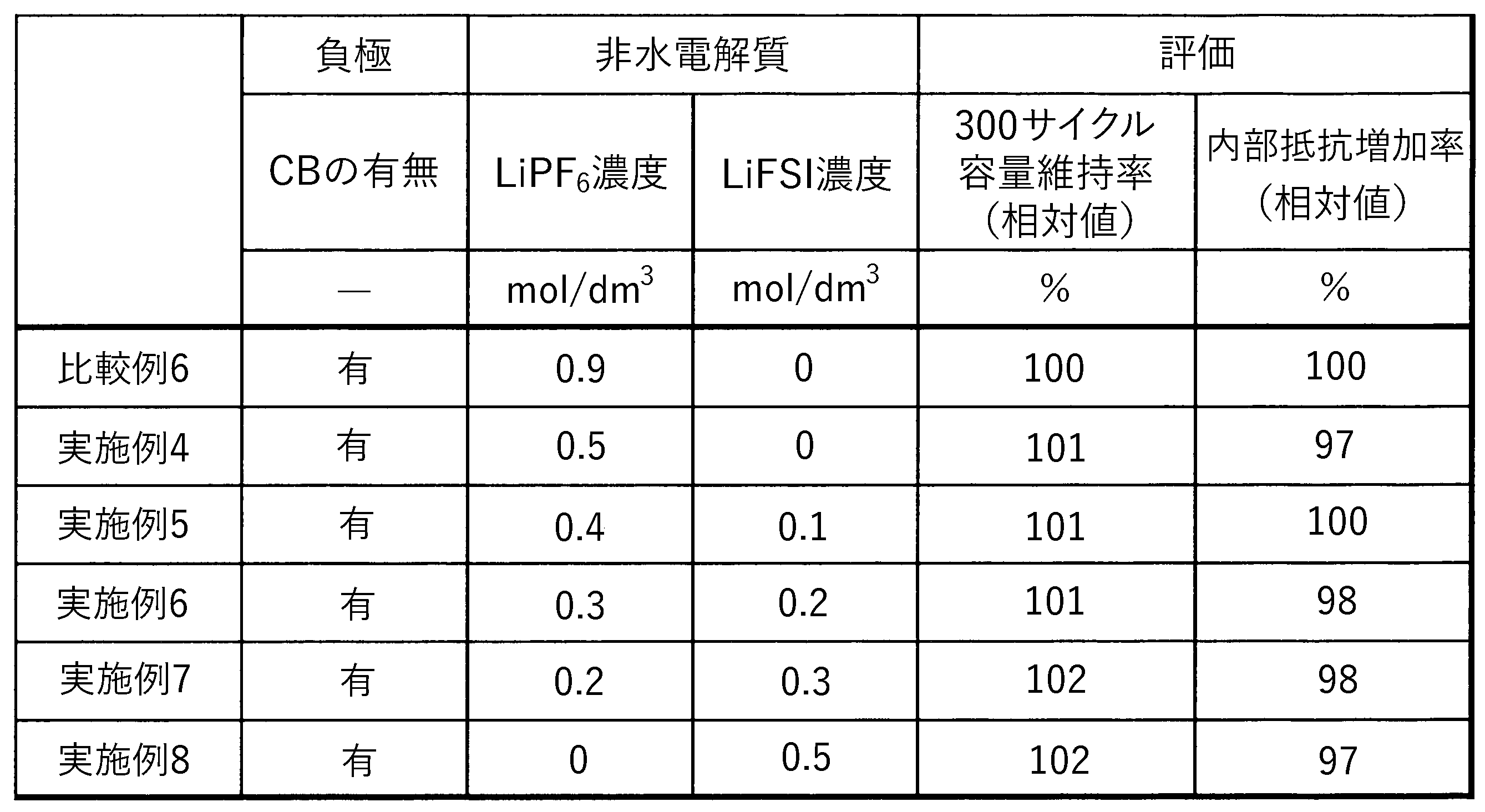
(正極の作製)
LiFePO4、アセチレンブラック及びPVDFを90:5:5の質量比(固形分換算)で含有し、NMPを分散媒とする正極ペーストを調製した。この正極ペーストをアルミニウム箔の表面に塗布し、乾燥することにより、正極を得た。 [Reference example 1]
(Preparation of positive electrode)
A positive electrode paste containing LiFePO 4 , acetylene black and PVDF at a mass ratio of 90:5:5 (in terms of solid content) and using NMP as a dispersion medium was prepared. This positive electrode paste was applied to the surface of an aluminum foil and dried to obtain a positive electrode.
黒鉛及びPVDFを92:8の質量比(固形分換算)で含有し、NMPを分散媒とする負極ペーストを調製した。この負極ペーストを銅箔の表面に塗布し、乾燥することにより、負極を得た。 (Preparation of negative electrode)
A negative electrode paste containing graphite and PVDF at a mass ratio of 92:8 (in terms of solid content) and using NMP as a dispersion medium was prepared. This negative electrode paste was applied to the surface of a copper foil and dried to obtain a negative electrode.
ECとDMCとEMCとを25:20:55の体積比で混合した非水溶媒に、電解質塩としてLiPF6を1.0mol/dm3の濃度で溶解させ、非水電解質を得た。 (Preparation of non-aqueous electrolyte)
A non-aqueous electrolyte was obtained by dissolving LiPF 6 as an electrolyte salt at a concentration of 1.0 mol/dm 3 in a non-aqueous solvent in which EC, DMC and EMC were mixed at a volume ratio of 25:20:55.
上述の正極と負極とをポリオレフィン製多孔質樹脂フィルムセパレータを介して巻回することで電極体を作成した。この電極体をアルミニウム製容器に挿入した後に、容器の蓋をレーザ溶接した。容器に設けられた注液孔を介して、容器に上述の非水電解質を注入したあと、注液孔を封止し、参考例1の非水電解質蓄電素子を得た。 (assembly)
An electrode body was produced by winding the above positive electrode and negative electrode with a polyolefin porous resin film separator interposed therebetween. After inserting this electrode assembly into an aluminum container, the lid of the container was laser-welded. After injecting the above-mentioned non-aqueous electrolyte into the container through an injection hole provided in the container, the injection hole was sealed to obtain a non-aqueous electrolyte storage element of Reference Example 1.
負極ペーストを、黒鉛、SBR及びCMCを97:2:1の質量比(固形分換算)で含有し、水を分散媒とする負極ペーストとしたこと以外は参考例1と同様にして、参考例2の非水電解質蓄電素子を得た。 [Reference example 2]
In the same manner as in Reference Example 1, except that the negative electrode paste contained graphite, SBR and CMC at a mass ratio of 97: 2: 1 (in terms of solid content) and water was used as a dispersion medium. No. 2 non-aqueous electrolyte storage device was obtained.
(充放電サイクル試験)
参考例の各非水電解質蓄電素子に対し、以下の充放電サイクル試験を行った。45℃において、3.6Vまで充電電流1.0Cで定電流充電したのちに、3.6Vで定電圧充電した。充電の終了条件は、充電時間の合計が3時間となるまでとした。その後、30分間の休止期間を設けた。その後、2.0Vまで放電電流1.0Cで定電流放電を行い、その後、30分間の休止期間を設けた。この充放電を500サイクル実施した。 [evaluation]
(Charge-discharge cycle test)
The following charge-discharge cycle test was performed on each non-aqueous electrolyte storage element of Reference Example. At 45.degree. The condition for terminating charging was until the total charging time reached 3 hours. A rest period of 30 minutes was then provided. After that, constant current discharge was performed at a discharge current of 1.0 C to 2.0 V, followed by a rest period of 30 minutes. This charging/discharging was performed for 500 cycles.
また、充放電サイクル前後で、50%SOCでの25℃における内部抵抗を上記と同様の方法で測定した。充放電サイクル試験後の内部抵抗の初期の内部抵抗からの増加量を初期の内部抵抗で除し、内部抵抗増加率(%)を求めた。 (Internal resistance increase rate)
In addition, the internal resistance at 25° C. at 50% SOC was measured by the same method as above before and after the charge/discharge cycle. The amount of increase in internal resistance after the charge-discharge cycle test from the initial internal resistance was divided by the initial internal resistance to obtain an internal resistance increase rate (%).
2 電極体
3 容器
4 正極端子
41 正極リード
5 負極端子
51 負極リード
20 蓄電ユニット
30 蓄電装置
1 Non-aqueous
Claims (6)
- リン酸鉄リチウムを含む正極と、
黒鉛及び非黒鉛質炭素の少なくとも一方、並びにカーボンブラックを含む負極と、
リチウム塩を含む非水電解質と
を備え、
上記非水電解質におけるリチウム塩の濃度が0.7mol/dm3以下である非水電解質蓄電素子。 a positive electrode comprising lithium iron phosphate;
a negative electrode comprising at least one of graphite and non-graphitic carbon and carbon black;
comprising a non-aqueous electrolyte containing a lithium salt and
A non-aqueous electrolyte storage element, wherein the non-aqueous electrolyte has a lithium salt concentration of 0.7 mol/dm 3 or less. - 上記リチウム塩がリチウムビス(フルオロスルホニル)イミドを含み、
上記リチウム塩に占めるリチウムビス(フルオロスルホニル)イミドの含有量が40mol%以上である請求項1に記載の非水電解質蓄電素子。 wherein the lithium salt comprises lithium bis(fluorosulfonyl)imide;
2. The non-aqueous electrolyte storage element according to claim 1, wherein the content of lithium bis(fluorosulfonyl)imide in said lithium salt is 40 mol % or more. - 上記リチウム塩がリチウムビス(フルオロスルホニル)イミド及びヘキサフルオロリン酸リチウムを含み、リチウムビス(フルオロスルホニル)イミドの含有量とヘキサフルオロリン酸リチウムの含有量との比(リチウムビス(フルオロスルホニル)イミド:ヘキサフルオロリン酸リチウム)がモル比で50:50から99:1の範囲内であり、上記リチウム塩に占めるリチウムビス(フルオロスルホニル)イミド及びヘキサフルオロリン酸リチウムの合計の含有量が90mol%以上100mol%以下である請求項1又は請求項2に記載の非水電解質蓄電素子。 The lithium salt contains lithium bis(fluorosulfonyl)imide and lithium hexafluorophosphate, and the ratio of the content of lithium bis(fluorosulfonyl)imide to the content of lithium hexafluorophosphate (lithium bis(fluorosulfonyl)imide : lithium hexafluorophosphate) is within the range of 50:50 to 99:1 in molar ratio, and the total content of lithium bis(fluorosulfonyl)imide and lithium hexafluorophosphate in the above lithium salt is 90 mol% 3. The non-aqueous electrolyte storage element according to claim 1, wherein the content is not less than 100 mol % and not more than 100 mol %.
- 上記負極に含まれる負極活物質における黒鉛及び非晶質炭素の合計の含有量が100質量%である請求項1又は請求項2に記載の非水電解質蓄電素子。 The non-aqueous electrolyte storage element according to claim 1 or 2, wherein the total content of graphite and amorphous carbon in the negative electrode active material contained in the negative electrode is 100% by mass.
- 上記負極に含まれる負極活物質における黒鉛及び非晶質炭素の合計の含有量が100質量%である請求項3に記載の非水電解質蓄電素子。 The non-aqueous electrolyte storage element according to claim 3, wherein the total content of graphite and amorphous carbon in the negative electrode active material contained in the negative electrode is 100% by mass.
- リン酸鉄リチウムを含む正極と、
黒鉛及び非黒鉛質炭素の少なくとも一方、並びにカーボンブラックを含む負極と、
ヘキサフルオロリン酸リチウムを含む非水電解質と
を備え、
上記非水電解質におけるヘキサフルオロリン酸リチウムの濃度が0.7mol/dm3以下である非水電解質蓄電素子。
a positive electrode comprising lithium iron phosphate;
a negative electrode comprising at least one of graphite and non-graphitic carbon and carbon black;
a non-aqueous electrolyte containing lithium hexafluorophosphate;
A nonaqueous electrolyte power storage device, wherein the concentration of lithium hexafluorophosphate in the nonaqueous electrolyte is 0.7 mol/dm 3 or less.
Priority Applications (3)
| Application Number | Priority Date | Filing Date | Title |
|---|---|---|---|
| EP22833010.6A EP4358220A1 (en) | 2021-06-29 | 2022-06-24 | Non-aqueous electrolyte power storage element |
| CN202280046850.8A CN117716556A (en) | 2021-06-29 | 2022-06-24 | Nonaqueous electrolyte storage element |
| JP2023531888A JPWO2023276863A1 (en) | 2021-06-29 | 2022-06-24 |
Applications Claiming Priority (2)
| Application Number | Priority Date | Filing Date | Title |
|---|---|---|---|
| JP2021-107627 | 2021-06-29 | ||
| JP2021107627 | 2021-06-29 |
Publications (1)
| Publication Number | Publication Date |
|---|---|
| WO2023276863A1 true WO2023276863A1 (en) | 2023-01-05 |
Family
ID=84691278
Family Applications (1)
| Application Number | Title | Priority Date | Filing Date |
|---|---|---|---|
| PCT/JP2022/025226 WO2023276863A1 (en) | 2021-06-29 | 2022-06-24 | Non-aqueous electrolyte power storage element |
Country Status (4)
| Country | Link |
|---|---|
| EP (1) | EP4358220A1 (en) |
| JP (1) | JPWO2023276863A1 (en) |
| CN (1) | CN117716556A (en) |
| WO (1) | WO2023276863A1 (en) |
Citations (4)
| Publication number | Priority date | Publication date | Assignee | Title |
|---|---|---|---|---|
| JP2011070802A (en) | 2009-09-24 | 2011-04-07 | Gs Yuasa Corp | Nonaqueous electrolyte secondary battery |
| JP2014209470A (en) * | 2013-03-28 | 2014-11-06 | 株式会社半導体エネルギー研究所 | Electrochemical device, and deterioration suppression method for the same |
| JP2016085837A (en) * | 2014-10-24 | 2016-05-19 | Tdk株式会社 | Lithium ion secondary battery |
| JP2017041426A (en) * | 2015-08-21 | 2017-02-23 | 株式会社日本触媒 | Lithium ion secondary battery |
-
2022
- 2022-06-24 WO PCT/JP2022/025226 patent/WO2023276863A1/en active Application Filing
- 2022-06-24 JP JP2023531888A patent/JPWO2023276863A1/ja active Pending
- 2022-06-24 CN CN202280046850.8A patent/CN117716556A/en active Pending
- 2022-06-24 EP EP22833010.6A patent/EP4358220A1/en active Pending
Patent Citations (4)
| Publication number | Priority date | Publication date | Assignee | Title |
|---|---|---|---|---|
| JP2011070802A (en) | 2009-09-24 | 2011-04-07 | Gs Yuasa Corp | Nonaqueous electrolyte secondary battery |
| JP2014209470A (en) * | 2013-03-28 | 2014-11-06 | 株式会社半導体エネルギー研究所 | Electrochemical device, and deterioration suppression method for the same |
| JP2016085837A (en) * | 2014-10-24 | 2016-05-19 | Tdk株式会社 | Lithium ion secondary battery |
| JP2017041426A (en) * | 2015-08-21 | 2017-02-23 | 株式会社日本触媒 | Lithium ion secondary battery |
Also Published As
| Publication number | Publication date |
|---|---|
| EP4358220A1 (en) | 2024-04-24 |
| CN117716556A (en) | 2024-03-15 |
| JPWO2023276863A1 (en) | 2023-01-05 |
Similar Documents
| Publication | Publication Date | Title |
|---|---|---|
| JP2020123465A (en) | Anode and manufacturing method of anode | |
| JP7215331B2 (en) | Method for manufacturing non-aqueous electrolyte storage element and non-aqueous electrolyte storage element | |
| US20230207784A1 (en) | Positive electrode and energy storage device | |
| CN115516660A (en) | Positive electrode for electricity storage element and electricity storage element | |
| JP2022134613A (en) | Positive electrode mixture for non-aqueous electrolyte storage element, positive electrode for non-aqueous electrolyte storage element, and non-aqueous electrolyte storage element | |
| WO2023276863A1 (en) | Non-aqueous electrolyte power storage element | |
| WO2022181516A1 (en) | Nonaqueous electrolyte power storage element | |
| WO2022249667A1 (en) | Nonaqueous electrolyte power storage element and power storage device | |
| WO2024029333A1 (en) | Non-aqueous electrolyte power storage element | |
| WO2023286718A1 (en) | Power storage element | |
| EP4290617A1 (en) | Nonaqueous electrolyte power storage element | |
| WO2023248769A1 (en) | Active material particles, electrode, power storage element and power storage device | |
| WO2023224070A1 (en) | Non-aqueous electrolyte power storage element | |
| WO2022163125A1 (en) | Nonaqueous electrolyte power storage element, power storage device, and method for producing nonaqueous electrolyte power storage element | |
| EP4250419A1 (en) | Nonaqueous electrolyte power storage element, electronic device, and automobile | |
| WO2023281960A1 (en) | Positive electrode, power storage element and power storage device | |
| WO2023100801A1 (en) | Nonaqueous electrolyte power storage element, device, and method for using nonaqueous electrolyte power storage element | |
| WO2023074559A1 (en) | Power storage element | |
| WO2023233790A1 (en) | Power storage element | |
| WO2022239861A1 (en) | Electric power storage element | |
| WO2023224071A1 (en) | Nonaqueous electrolyte power storage element | |
| WO2023190422A1 (en) | Positive electrode for non-aqueous electrolyte power storage element, and non-aqueous electrolyte power storage element comprising same | |
| WO2022209815A1 (en) | Positive electrode active material for nonaqueous electrolyte power storage elements, positive electrode for nonaqueous electrolyte power storage elements, nonaqueous electrolyte power storage element, power storage unit, and power storage device | |
| WO2022168845A1 (en) | Nonaqueous electrolyte power storage element and power storage device | |
| WO2023199942A1 (en) | Non-aqueous electrolyte storage element |
Legal Events
| Date | Code | Title | Description |
|---|---|---|---|
| 121 | Ep: the epo has been informed by wipo that ep was designated in this application |
Ref document number: 22833010 Country of ref document: EP Kind code of ref document: A1 |
|
| WWE | Wipo information: entry into national phase |
Ref document number: 2023531888 Country of ref document: JP |
|
| WWE | Wipo information: entry into national phase |
Ref document number: 2022833010 Country of ref document: EP |
|
| NENP | Non-entry into the national phase |
Ref country code: DE |
|
| ENP | Entry into the national phase |
Ref document number: 2022833010 Country of ref document: EP Effective date: 20240115 |