US11651908B2 - Method of winding coilware, computer program product, control device, and winding machine - Google Patents
Method of winding coilware, computer program product, control device, and winding machine Download PDFInfo
- Publication number
- US11651908B2 US11651908B2 US17/029,308 US202017029308A US11651908B2 US 11651908 B2 US11651908 B2 US 11651908B2 US 202017029308 A US202017029308 A US 202017029308A US 11651908 B2 US11651908 B2 US 11651908B2
- Authority
- US
- United States
- Prior art keywords
- winding
- spectrum
- compensation signal
- drive
- dependent compensation
- Prior art date
- Legal status (The legal status is an assumption and is not a legal conclusion. Google has not performed a legal analysis and makes no representation as to the accuracy of the status listed.)
- Active, expires
Links
Images


Classifications
-
- B—PERFORMING OPERATIONS; TRANSPORTING
- B65—CONVEYING; PACKING; STORING; HANDLING THIN OR FILAMENTARY MATERIAL
- B65H—HANDLING THIN OR FILAMENTARY MATERIAL, e.g. SHEETS, WEBS, CABLES
- B65H23/00—Registering, tensioning, smoothing or guiding webs
- B65H23/04—Registering, tensioning, smoothing or guiding webs longitudinally
- B65H23/18—Registering, tensioning, smoothing or guiding webs longitudinally by controlling or regulating the web-advancing mechanism, e.g. mechanism acting on the running web
- B65H23/195—Registering, tensioning, smoothing or guiding webs longitudinally by controlling or regulating the web-advancing mechanism, e.g. mechanism acting on the running web in winding mechanisms or in connection with winding operations
-
- B—PERFORMING OPERATIONS; TRANSPORTING
- B65—CONVEYING; PACKING; STORING; HANDLING THIN OR FILAMENTARY MATERIAL
- B65H—HANDLING THIN OR FILAMENTARY MATERIAL, e.g. SHEETS, WEBS, CABLES
- B65H54/00—Winding, coiling, or depositing filamentary material
- B65H54/02—Winding and traversing material on to reels, bobbins, tubes, or like package cores or formers
- B65H54/10—Winding and traversing material on to reels, bobbins, tubes, or like package cores or formers for making packages of specified shapes or on specified types of bobbins, tubes, cores, or formers
-
- H—ELECTRICITY
- H01—ELECTRIC ELEMENTS
- H01G—CAPACITORS; CAPACITORS, RECTIFIERS, DETECTORS, SWITCHING DEVICES, LIGHT-SENSITIVE OR TEMPERATURE-SENSITIVE DEVICES OF THE ELECTROLYTIC TYPE
- H01G13/00—Apparatus specially adapted for manufacturing capacitors; Processes specially adapted for manufacturing capacitors not provided for in groups H01G4/00 - H01G11/00
- H01G13/02—Machines for winding capacitors
-
- B—PERFORMING OPERATIONS; TRANSPORTING
- B65—CONVEYING; PACKING; STORING; HANDLING THIN OR FILAMENTARY MATERIAL
- B65H—HANDLING THIN OR FILAMENTARY MATERIAL, e.g. SHEETS, WEBS, CABLES
- B65H23/00—Registering, tensioning, smoothing or guiding webs
- B65H23/04—Registering, tensioning, smoothing or guiding webs longitudinally
- B65H23/18—Registering, tensioning, smoothing or guiding webs longitudinally by controlling or regulating the web-advancing mechanism, e.g. mechanism acting on the running web
- B65H23/182—Registering, tensioning, smoothing or guiding webs longitudinally by controlling or regulating the web-advancing mechanism, e.g. mechanism acting on the running web in unwinding mechanisms or in connection with unwinding operations
- B65H23/1825—Registering, tensioning, smoothing or guiding webs longitudinally by controlling or regulating the web-advancing mechanism, e.g. mechanism acting on the running web in unwinding mechanisms or in connection with unwinding operations and controlling web tension
-
- B—PERFORMING OPERATIONS; TRANSPORTING
- B65—CONVEYING; PACKING; STORING; HANDLING THIN OR FILAMENTARY MATERIAL
- B65H—HANDLING THIN OR FILAMENTARY MATERIAL, e.g. SHEETS, WEBS, CABLES
- B65H23/00—Registering, tensioning, smoothing or guiding webs
- B65H23/04—Registering, tensioning, smoothing or guiding webs longitudinally
- B65H23/18—Registering, tensioning, smoothing or guiding webs longitudinally by controlling or regulating the web-advancing mechanism, e.g. mechanism acting on the running web
- B65H23/182—Registering, tensioning, smoothing or guiding webs longitudinally by controlling or regulating the web-advancing mechanism, e.g. mechanism acting on the running web in unwinding mechanisms or in connection with unwinding operations
- B65H23/185—Registering, tensioning, smoothing or guiding webs longitudinally by controlling or regulating the web-advancing mechanism, e.g. mechanism acting on the running web in unwinding mechanisms or in connection with unwinding operations motor-controlled
-
- B—PERFORMING OPERATIONS; TRANSPORTING
- B65—CONVEYING; PACKING; STORING; HANDLING THIN OR FILAMENTARY MATERIAL
- B65H—HANDLING THIN OR FILAMENTARY MATERIAL, e.g. SHEETS, WEBS, CABLES
- B65H23/00—Registering, tensioning, smoothing or guiding webs
- B65H23/04—Registering, tensioning, smoothing or guiding webs longitudinally
- B65H23/18—Registering, tensioning, smoothing or guiding webs longitudinally by controlling or regulating the web-advancing mechanism, e.g. mechanism acting on the running web
- B65H23/195—Registering, tensioning, smoothing or guiding webs longitudinally by controlling or regulating the web-advancing mechanism, e.g. mechanism acting on the running web in winding mechanisms or in connection with winding operations
- B65H23/1955—Registering, tensioning, smoothing or guiding webs longitudinally by controlling or regulating the web-advancing mechanism, e.g. mechanism acting on the running web in winding mechanisms or in connection with winding operations and controlling web tension
-
- B—PERFORMING OPERATIONS; TRANSPORTING
- B65—CONVEYING; PACKING; STORING; HANDLING THIN OR FILAMENTARY MATERIAL
- B65H—HANDLING THIN OR FILAMENTARY MATERIAL, e.g. SHEETS, WEBS, CABLES
- B65H23/00—Registering, tensioning, smoothing or guiding webs
- B65H23/04—Registering, tensioning, smoothing or guiding webs longitudinally
- B65H23/18—Registering, tensioning, smoothing or guiding webs longitudinally by controlling or regulating the web-advancing mechanism, e.g. mechanism acting on the running web
- B65H23/195—Registering, tensioning, smoothing or guiding webs longitudinally by controlling or regulating the web-advancing mechanism, e.g. mechanism acting on the running web in winding mechanisms or in connection with winding operations
- B65H23/198—Registering, tensioning, smoothing or guiding webs longitudinally by controlling or regulating the web-advancing mechanism, e.g. mechanism acting on the running web in winding mechanisms or in connection with winding operations motor-controlled (Controlling electrical drive motors therefor)
-
- B—PERFORMING OPERATIONS; TRANSPORTING
- B65—CONVEYING; PACKING; STORING; HANDLING THIN OR FILAMENTARY MATERIAL
- B65H—HANDLING THIN OR FILAMENTARY MATERIAL, e.g. SHEETS, WEBS, CABLES
- B65H59/00—Adjusting or controlling tension in filamentary material, e.g. for preventing snarling; Applications of tension indicators
- B65H59/38—Adjusting or controlling tension in filamentary material, e.g. for preventing snarling; Applications of tension indicators by regulating speed of driving mechanism of unwinding, paying-out, forwarding, winding, or depositing devices, e.g. automatically in response to variations in tension
- B65H59/384—Adjusting or controlling tension in filamentary material, e.g. for preventing snarling; Applications of tension indicators by regulating speed of driving mechanism of unwinding, paying-out, forwarding, winding, or depositing devices, e.g. automatically in response to variations in tension using electronic means
- B65H59/385—Regulating winding speed
-
- B—PERFORMING OPERATIONS; TRANSPORTING
- B65—CONVEYING; PACKING; STORING; HANDLING THIN OR FILAMENTARY MATERIAL
- B65H—HANDLING THIN OR FILAMENTARY MATERIAL, e.g. SHEETS, WEBS, CABLES
- B65H59/00—Adjusting or controlling tension in filamentary material, e.g. for preventing snarling; Applications of tension indicators
- B65H59/38—Adjusting or controlling tension in filamentary material, e.g. for preventing snarling; Applications of tension indicators by regulating speed of driving mechanism of unwinding, paying-out, forwarding, winding, or depositing devices, e.g. automatically in response to variations in tension
- B65H59/384—Adjusting or controlling tension in filamentary material, e.g. for preventing snarling; Applications of tension indicators by regulating speed of driving mechanism of unwinding, paying-out, forwarding, winding, or depositing devices, e.g. automatically in response to variations in tension using electronic means
- B65H59/387—Regulating unwinding speed
-
- H—ELECTRICITY
- H01—ELECTRIC ELEMENTS
- H01F—MAGNETS; INDUCTANCES; TRANSFORMERS; SELECTION OF MATERIALS FOR THEIR MAGNETIC PROPERTIES
- H01F41/00—Apparatus or processes specially adapted for manufacturing or assembling magnets, inductances or transformers; Apparatus or processes specially adapted for manufacturing materials characterised by their magnetic properties
- H01F41/02—Apparatus or processes specially adapted for manufacturing or assembling magnets, inductances or transformers; Apparatus or processes specially adapted for manufacturing materials characterised by their magnetic properties for manufacturing cores, coils, or magnets
- H01F41/04—Apparatus or processes specially adapted for manufacturing or assembling magnets, inductances or transformers; Apparatus or processes specially adapted for manufacturing materials characterised by their magnetic properties for manufacturing cores, coils, or magnets for manufacturing coils
- H01F41/06—Coil winding
- H01F41/094—Tensioning or braking devices
-
- H—ELECTRICITY
- H01—ELECTRIC ELEMENTS
- H01G—CAPACITORS; CAPACITORS, RECTIFIERS, DETECTORS, SWITCHING DEVICES, LIGHT-SENSITIVE OR TEMPERATURE-SENSITIVE DEVICES OF THE ELECTROLYTIC TYPE
- H01G4/00—Fixed capacitors; Processes of their manufacture
- H01G4/32—Wound capacitors
-
- H—ELECTRICITY
- H01—ELECTRIC ELEMENTS
- H01M—PROCESSES OR MEANS, e.g. BATTERIES, FOR THE DIRECT CONVERSION OF CHEMICAL ENERGY INTO ELECTRICAL ENERGY
- H01M10/00—Secondary cells; Manufacture thereof
- H01M10/05—Accumulators with non-aqueous electrolyte
- H01M10/058—Construction or manufacture
- H01M10/0587—Construction or manufacture of accumulators having only wound construction elements, i.e. wound positive electrodes, wound negative electrodes and wound separators
-
- H—ELECTRICITY
- H01—ELECTRIC ELEMENTS
- H01M—PROCESSES OR MEANS, e.g. BATTERIES, FOR THE DIRECT CONVERSION OF CHEMICAL ENERGY INTO ELECTRICAL ENERGY
- H01M10/00—Secondary cells; Manufacture thereof
- H01M10/04—Construction or manufacture in general
- H01M10/0431—Cells with wound or folded electrodes
-
- Y—GENERAL TAGGING OF NEW TECHNOLOGICAL DEVELOPMENTS; GENERAL TAGGING OF CROSS-SECTIONAL TECHNOLOGIES SPANNING OVER SEVERAL SECTIONS OF THE IPC; TECHNICAL SUBJECTS COVERED BY FORMER USPC CROSS-REFERENCE ART COLLECTIONS [XRACs] AND DIGESTS
- Y02—TECHNOLOGIES OR APPLICATIONS FOR MITIGATION OR ADAPTATION AGAINST CLIMATE CHANGE
- Y02E—REDUCTION OF GREENHOUSE GAS [GHG] EMISSIONS, RELATED TO ENERGY GENERATION, TRANSMISSION OR DISTRIBUTION
- Y02E60/00—Enabling technologies; Technologies with a potential or indirect contribution to GHG emissions mitigation
- Y02E60/10—Energy storage using batteries
-
- Y—GENERAL TAGGING OF NEW TECHNOLOGICAL DEVELOPMENTS; GENERAL TAGGING OF CROSS-SECTIONAL TECHNOLOGIES SPANNING OVER SEVERAL SECTIONS OF THE IPC; TECHNICAL SUBJECTS COVERED BY FORMER USPC CROSS-REFERENCE ART COLLECTIONS [XRACs] AND DIGESTS
- Y02—TECHNOLOGIES OR APPLICATIONS FOR MITIGATION OR ADAPTATION AGAINST CLIMATE CHANGE
- Y02P—CLIMATE CHANGE MITIGATION TECHNOLOGIES IN THE PRODUCTION OR PROCESSING OF GOODS
- Y02P70/00—Climate change mitigation technologies in the production process for final industrial or consumer products
- Y02P70/50—Manufacturing or production processes characterised by the final manufactured product
Definitions
- the present invention relates to a method and a computer program product for winding coilware from a supply roll onto a winding body.
- the present invention also relates to a control device for a winding machine and such a winding machine.
- the winding tension corresponds to the force (per cross-sectional area) with which the coilware is wound onto the winding body.
- the winding tension can be adjusted.
- the winding tension is the tensile stress of the coilware.
- EP 2 485 227 A1 describes a wire-winding machine and control for such a wire-winding machine.
- EP 3 333 106 A1 describes a method of winding coilware from a supply roll onto a winding body having a non-circular cross section, in which the coilware is provided from the supply roll and is wound onto the winding body, where the winding tension of the coilware is adjustable to an envisaged winding tension, and where a rotational speed of the winding body is controlled or regulated to adjust the winding tension and/or the winding tension is adjusted to the envisaged winding tension by an adjustment unit.
- the imbalance of two different deflection rolls of the winding machine may have a detrimental influence on the web tension.
- the resultant defect can certainly be measured but the assignment of the partial components of the defect and the feedforward control of the corresponding partial components at the correct location has hitherto not been possible in conventional winding machines.
- feedforward control of the signal at a wrong location for example, not at the device causing the partial component of the defect, the quality of the product could even be made worse.
- a method of winding coilware from a supply roll onto a winding body having a non-circular cross section of a winding machine in which the coilware is provided from the supply roll and the coilware provided from the supply roll is wound onto the winding body over at least one deflection roll, where a current winding tension of the coilware is adjusted to a target winding tension depending on a position-dependent compensation signal, stored in a memory unit, for the compensation of a variable free length of the coilware between the deflection roll and the winding body because of the non-circular cross section of the coilware.
- the included frequency components or partial spectra of the compensation signal particularly depend on the geometry of the winding body, the geometric arrangement of the winder relative to the first deflection roll and the process speed.
- the mechanical system of the winding machine in particular comprising the stiffness of the mechanism, the gears, the belts and the coupling, it is not possible for all the frequency components to be transmitted to the load side without distortion. This can lead to from low negative influences on the process quality as far as mechanical damage to the winding machine.
- the method comprises the providing the coilware from the supply roll, and winding the coilware provided from the supply roll over at least one deflection roll onto the winding body, where at least one of the drives is adjusted as a function of a position-dependent compensation signal at least partly compensating a defect.
- the position-dependent compensation signal for the respective drive is provided by a) acquiring an interference variable representing the defect in the time domain during a winding operation, b) transforming the acquired interference variable from the time domain into a spectrum in the frequency domain, c) filtering the spectrum via a filter specific to the winding device assigned to the drive, d) transforming the filtered spectrum from the frequency domain into the time domain to provide a time-dependent compensation signal, and e) transforming the time-dependent compensation signal into the position-dependent compensation signal.
- an optimized position-dependent compensation signal can be generated and utilized during the winding operation.
- a specific position-dependent compensation signal is generated and utilized during the winding operation, in particular for the feedforward control of the respective drive.
- the present method can be used without knowledge of the geometry of the winding body, because the position-dependent compensation signal can be derived from the acquired interference variable as such.
- the present method is flexible, in particular as far as the mechanism of the winding machine is concerned, because the defect is learned through the application of steps a) to e).
- the winding body has, for example, a circular cross section, in particular a non-circular cross section, because the present compensation is then particularly effective.
- the step a) is performed in particular during a measurement run, i.e., before normal operation of the winding machine, during which the interference variable that is critical for the process quality is recorded.
- the acquired or recorded interference variable is then transformed into the frequency domain via a transformation, for example a Fourier transformation such as a fast Fourier transform (FFT) and can then be analyzed. High-frequency components of this signal that cannot be transmitted by the drive train can be filtered out of the signal in the step.
- the filtered signal is converted into the time domain again with an inverse transformation, such as an inverse FFT.
- the compensation signal obtained here can then undergo feedforward control after a transformation from the time domain into the spatial domain, in order to compensate for the disruptive process influences of the winding operation.
- the present method has the advantage that other mechanical influences, such as for example imbalances of the deflection roll or other winding devices during the assembly, are likewise taken into account automatically.
- the process speed can advantageously be increased with an existing mechanism of the winding machine.
- the process quality can also be increased by the present method with the existing mechanism of the winding machine.
- Defects during the winding operation can be caused, for example, by imbalances in the assembly of one or more of the winding devices or by a variable free length of the coilware between the deflection roll and the winding body, in particular when a winding body having a non-circular cross section is used.
- the compensation signal or the compensation signals can advantageously compensate for these defects.
- the interference variable is in particular a difference, between a current value and a target value, acquired over a multiplicity of windings or at least part of a winding cycle.
- a difference can be at least partly caused, for example in the case of a winding body having a non-circular cross section, by a variable free length of the coilware between the deflection roll and the winding body because of the non-circular cross section of the coilware.
- Examples of such current values and target values comprise a current winding tension of the coilware and a target winding tension of the coilware and also a current torque and a target torque.
- a further example of an interference variable is a dancer position deviation of a target position of the dancer roll from a current position of the dancer roll during the winding operation.
- the position-dependent compensation signal is particularly calculated in advance for an overall winding operation or for a partial winding operation and stored in a memory unit.
- the calculated compensation signal is stored in a table or polynomial table, also called a cam disk.
- the path length of the coilware between the deflection roll and the winding body is designated as the free length of the coilware. If multiple deflection rolls are provided in the winding machine, then the deflection roll connected immediately upstream of the winding body is meant.
- the free length of the coilware is the path length between the contact point of the coilware on the deflection roll and the contact point of the coilware on the winding body.
- the winding tension is understood to be the tension, in particular the mechanical tension, of the coilware during winding.
- the winding tension is defined as the force that acts on the coilware perpendicularly to the cross-sectional area thereof, divided by the cross-sectional area.
- the target winding tension is understood to be the winding tension with which the coilware is to be wound onto the winding body.
- the target winding tension can also be designated as the envisaged winding tension.
- the target winding tension can be represented as a function of the alignment of the winding body. By way of example, this is relevant when winding wire coilware around an angular winding body, in order to achieve an optimized result.
- the winding tension is preferably proportional to the curvature of the winding body at the contact point of the winding body. Such a proportionality is particularly advantageous when winding metal wires.
- a non-circular cross section is understood to be a cross section that deviates from a circular shape. This means that the coilware has a non-constant diameter, i.e., at least two different diameters.
- such a winding body having a non-circular cross section is elliptical or rectangular.
- a supply roll is in particular understood to mean a device for keeping the coilware in the winding machine.
- the supply roll is a wire roll or a roll-on which foil is rolled up.
- the winding body can be assigned a first rotational speed, whereas the supply roll can be assigned a second rotational speed, such that the supply roll provides the coilware at a speed that is proportional to the second rotational speed.
- the deflection roll preferably means that deflection roll from which the coilware is led to the winding body.
- the winding tension can also be designated as web tension or coilware tension.
- the winding tension can also be designated as web tension or coilware tension.
- the current winding tension is constant, in particular during a winding cycle of N revolutions of the winding body.
- the current winding tension is preferably to be kept constant during battery cell manufacture and the winding of capacitors.
- “constant” is to be understood in particular to mean that the winding tension remains constant during the winding operation, in particular at the contact point of the coilware on the (in particular already wound) winding body.
- the filter assigned to the drive is configured as a function of parameters of the winding device assigned to the drive.
- the supply roll has a specific rotational frequency (operating frequency) during operation. Consequently, if defects occur during the winding operation, then the supply roll has components in the acquired interference variable at this specific rotational frequency or one or more of its harmonics.
- the filter assigned to the drive of the supply roll is then configured.
- the filter configured in this way can then filter out the components in the interference variable caused by the supply roll in the frequency domain, such that the compensation signal to be generated for the drive of the supply roll can be provided appropriately. Filtering or filtering out can also be designated as extraction.
- frequencies of the spectrum above a specific limiting frequency can be masked out or suppressed.
- Such frequencies above the specific limiting frequency are advantageously suppressed, because they cannot be transmitted by the mechanism of the winding machine and therefore do not have to be taken into account during the generation of the compensation signal or the compensation signals. This advantageously reduces the damage potential.
- step c during the filtering of the spectrum in step c), those partial spectra of the spectrum that depend on an operating frequency of the winding device assigned to the drive are filtered out. Then, in step d), the partial spectra that are filtered out are transformed from the frequency domain into the time domain in order to provide the time-dependent compensation signal for the drive. Therefore, specific compensation signals can be generated for the respective drive.
- the respective partial spectrum relates to the respective winding device influencing the respective defect, and the corresponding compensation signal is generated for the drive of this winding device.
- step c during the filtering of the spectrum in step c), those partial spectra of the spectrum which correspond to an operating frequency of the winding device assigned to the drive or one of its harmonics are filtered out. Then, in step d), the partial spectra that are filtered out are transformed from the frequency domain into the time domain to provide the time-dependent compensation signal for the drive.
- the spectrum is analyzed to assign at least one partial spectrum to a winding device at least partly causing the defect.
- the winding machine comprises a multiplicity of winding devices, such as the supply roll, the winding body and, for example, the dancer roll.
- the respective winding device will in particular cause only part of the defect and therefore contribute only partially to the interference variable. Accordingly, the spectrum of the interference variable is analyzed, and the respective partial spectrum is assigned to the respectively causative winding device.
- the respective partial spectrum assigned to one of the winding devices is then filtered or determined, i.e., filtered or determined as a function of a result of the analysis. Consequently, the filtered partial spectrum is transformed from the frequency domain into the time domain to provide at least part of the time-dependent compensation signal for the drive assigned to the causative winding device.
- the compensation signal provided is thus respectively specific to the causative winding device and is used, for example, for the feedforward control of the drive of the causative winding device.
- step a) the interference variable is acquired as a time-discrete signal in the time domain during a measurement run, in particular before normal operation of the winding machine.
- the time-discrete signal as a representation of the acquired interference variable, is then transformed into the frequency domain in step b), for example by means of an FFT.
- step b) the acquired interference variable is transformed from the time domain into the spectrum in the frequency domain by means of a frequency transformation, in particular via a Fourier transformation.
- a frequency transformation in particular via a Fourier transformation.
- the Fourier transformation comprise FFT (fast Fourier transformation) and DFT (discrete Fourier transformation).
- a fast Fourier transformation is used as a Fourier transformation.
- the interference variable is sampled at a first sampling rate to provide a time-discrete signal.
- the sampled signal is interpolated via an interpolation, such as via C-splines, and the interpolated signal is sampled at a second sampling rate, such that the number of sampling points corresponds to a power of two.
- the signal sampled at the second sampling rate is then transformed into the frequency domain via the FFT.
- the first sampling rate can in particular also be designated as a real sampling rate of the control device or the controller.
- the second sampling rate can in particular also be designated as a manipulated sampling rate of the cam dis
- feedforward control of the drive is performed via the position-dependent compensation signal.
- the time-dependent compensation signal is transformed into the position-dependent compensation signal as a function of a respective position of the winding body for a winding cycle from N revolutions of the winding body and is stored in a table of a memory unit.
- the respective position of the winding body for a winding cycle from N revolutions of the winding body is determined as a function of the winding length of the coilware and of the rotational speed of the winding body.
- a polynomial table is used as a table for storing the position-dependent compensation signal.
- the polynomial table can also be designated as a cam disk.
- a respective position-dependent compensation signal is provided via a respective execution of steps a) to e). Therefore, for the respective drive of each of the winding devices, a specific position-dependent compensation signal is provided, such that the defects can be compensated in an optimal way and in particular at the correct points of the winding machine.
- the winding machine has a dancer roll and a feed, which is arranged between the supply roll and the dancer roll.
- the dancer roll acts as an adjustment unit or as part of an adjustment unit.
- the adjustment unit can have a coilware accumulator.
- the coilware is led over a deflection roll, where the deflection roll is coupled to a servo motor and the winding tension is adjusted with an adjustment of the rotational speed.
- a coilware accumulator has a multiplicity of deflection rolls, where the coilware is kept by the multiplicity of deflection rolls on a path that is variable in length. By changing the position of at least one of the deflection rolls, an adjustment of the length of the path is possible.
- the length of the path of the coilware corresponds to the capacity of the coilware accumulator.
- the change in the position of the respective deflection roll is in particular made via an actuator.
- a coilware accumulator can be combined with a dancer roll to equalize fluctuations of the winding tension.
- a computer program product e.g., a non-transitory computer-readable medium which, on a program-controlled device, causes the execution of the disclosed embodiments of the method for winding coilware from a supply roll onto a winding body.
- a computer program product such as a computer program means
- control device for a winding machine, where the control device is configured to execute the disclosed embodiments of the method for winding coilware from a supply roll onto a winding body with the aid of drives.
- the control device can be implemented in hardware and/or in software.
- the control device can be configured as a device, as part of a device, such as a computer or as a microprocessor, or as a control computer.
- the control device can be configured as a computer program product, as a function, as a routine, as part of a program code or as an executable object.
- the control device is configured to adjust at least one of the drives as a function of a position-dependent compensation signal at least partly compensating a defect when winding the coilware provided from the supply roll onto the winding body over at least one deflection roll.
- the control device includes a first unit for acquiring an interference variable representing the defect in the time domain during a winding operation, a second unit for transforming the acquired interference variable from the time domain into a spectrum in the frequency domain, a third unit for filtering the spectrum via a filter that is specific to the winding device assigned to the drive, a fourth unit for transforming the filtered spectrum from the frequency domain into the time domain to provide a time-dependent compensation signal, and a fifth unit for transforming the time-dependent compensation signal into the position-dependent compensation signal.
- Each respective unit can be implemented in hardware and/or in software.
- the respective unit can be formed as a device or as part of a device, such as a computer or as a microprocessor, or as a control computer.
- the respective unit can be configured as a computer program product, as a function, as a routine, as part of a program code or as an executable object.
- the winding machine has a plurality of winding devices that can be driven by a plurality of drives and that comprise at least one supply roll for providing the coilware and a winding body, and a control device in accordance with the invention.
- FIG. 1 shows a schematic view of an exemplary embodiment of a winding machine
- FIG. 2 shows a schematic flow chart of an exemplary embodiment of a method of winding coilware from a supply roll onto a winding body
- FIG. 3 shows a schematic block diagram of an exemplary embodiment of a method of providing position-dependent compensation signals for drives of two winding devices of the winding machine according to FIG. 1 ;
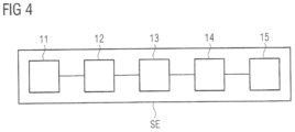
- FIG. 4 shows a schematic block diagram of an exemplary embodiment of a control device for a winding machine.
- FIG. 1 A schematic view of an exemplary embodiment of a winding machine 10 is illustrated in FIG. 1 .
- FIG. 2 shows a schematic flow chart of an exemplary embodiment of a method of winding coilware D from a supply roll 4 of the winding machine 10 onto a winding body 1 having a non-circular cross section.
- FIGS. 1 and 2 will be explained below with reference to each other.
- the winding machine 10 of FIG. 1 comprises a winding body 1 , a deflection roll 2 , a dancer roll 3 , a supply roll 4 and a feed 5 .
- the dancer roll 3 serves as an adjustment unit EE.
- the adjustment unit EE can have a coilware brake or a coilware accumulator.
- the feed 5 is arranged between the supply roll 4 and the dancer roll 3 and supplies the dancer roll 3 with the coilware D.
- the winding body 1 and the supply roll 4 can be driven via drives M 1 , M 4 .
- the drive M 1 is assigned to the winding body 1
- the drive M 4 is assigned to the supply roll 4 .
- the winding body 1 and the supply roll 4 are therefore examples of winding devices of the winding machine 10 which can be driven by drives M 1 , M 4 .
- the feed 5 can also be assigned a drive (not shown).
- the drives M 1 , M 4 can be controlled or regulated via a control device SE.
- the control device SE controls or regulates the drives M 1 , M 4 or motors of the winding body 1 and/or the supply roll 4 .
- the winding body 1 rotates at a first rotational speed W 1 during the winding operation.
- the supply roll 4 rotates at a second rotational speed W 4 .
- the coilware D is wound around the winding body 1 .
- the coilware D moves through the winding machine 10 at a specific speed.
- the coilware D has a specific winding tension.
- the specific winding tension is adjusted to a target winding tension or envisaged winding tension with the aid of the drive M 1 of the winding body 1 and with the aid of the drive M 4 for the supply roll 4 .
- the coilware D is led from the supply roll 4 to the winding body 1 over a deflection roll 2 .
- the coilware D from the deflection roll 2 is wound onto the winding body 1 .
- P 1 designates the contact point of the coilware D on the winding body 1
- P 2 the contact point of the coilware D on the deflection roll 2
- P 3 the contact point of the coilware D on the supply roll 4 .
- the coilware D leaves the deflection roll 2 at the contact point P 2 .
- the coilware D touches the winding body 1 at the contact point P 1 .
- the free length x extends between the contact point P 1 and the contact point P 2 .
- the free length x corresponds to the length of the coilware D between the deflection roll 2 and the winding body 1 .
- the free length x changes periodically during the winding operation.
- the contact point P 2 on the deflection roll 2 likewise changes periodically.
- the block 100 in FIG. 2 designates a measurement run for generating the position-dependent compensation signals k 1 ( ⁇ ), k 4 ( ⁇ ), and block 200 designates an operation (normal operation) of the winding machine 10 .
- FIG. 3 describes details with regard to the generation of the position-dependent compensation signal k 1 ( ⁇ ) for the drive M 1 of the winding body 1 and of the position-dependent compensation signal k 4 ( ⁇ ) for the drive M 4 of the supply roll 4 .
- the example of the method of FIG. 2 comprises the measurement run 100 having the steps 110 to 150 and the normal operation 200 having the steps 210 and 220 .
- the position-dependent compensation signal k 1 ( ⁇ ), k 4 ( ⁇ ) for the respective drive M 1 , M 4 is provided by the following steps 110 to 150 .
- step 110 an interference variable SG representing the defect during winding is acquired, in particular sampled as a time-discrete signal, in the time domain during a measurement run, in particular before a normal operation 200 of the winding machine 10 .
- step 120 the acquired interference variable SG is transformed from the time domain into a spectrum S in the frequency domain.
- a Fourier transformation for example, a fast Fourier transformation (FFT) is used.
- the interference variable SG is sampled via a first sampling rate to provide a time-discrete signal.
- the sampled signal is then interpolated via C-splines and the interpolated signal is sampled at a second sampling rate, such that the number of sample points corresponds to a power of two.
- the signal sampled at the second sample rate is then transformed into the frequency domain via the FFT.
- step 130 the spectrum S is filtered via a filter F 1 , F 4 that is specific to the winding device 1 , 4 assigned to the drive M 1 , M 4 .
- the winding body 1 as a winding device, is assigned the drive M 1 .
- the drive M 1 is in turn assigned a specific filter F 1 (see FIG. 3 ).
- the drive M 4 for the supply roll 4 is assigned the drive M 4 .
- the drive M 4 is assigned to the filter F 4 (see FIG. 3 ).
- step 140 the filtered spectrum (see TS 1 , TS 4 in FIG. 3 ) is transformed from the frequency domain into the time domain to provide a time-dependent compensation signal k 1 ( t ), k 4 ( t ).
- a time-dependent compensation signal k 1 ( t ), k 4 ( t ) is used.
- an inverse transformation relative to that in step 120 is used. For example, if an FFT has been used in step 120 , an inverse FFT is used in step 140 .
- step 150 the time-dependent compensation signal k 1 ( t ), k 4 ( t ) is transformed into the position-dependent compensation signal k 1 ( ⁇ ), k 4 ( ⁇ ).
- the feedforward control of the respective drive M 1 , M 4 can be then be implemented via the respective position-dependent compensation signal k 1 ( ⁇ ), k 4 ( ⁇ ).
- a position-dependent compensation signal k 1 ( ⁇ ) is generated for the drive M 1 of the winding body 1
- a further position-dependent compensation signal k 4 ( ⁇ ) is generated for the drive M 4 of the supply roll 4 .
- FIG. 3 shows a detailed schematic flow chart of an exemplary embodiment of a method of generating a position-dependent compensation signal k 1 ( ⁇ ) for the drive M 1 of the winding body 1 and a position-dependent compensation signal k 4 ( ⁇ ) for the supply roll 4 .
- the steps 110 to 150 of the block 100 of FIG. 3 are based on the steps 110 to 150 of the block 100 of FIG. 2 , where steps 130 to 150 for the two drives M 1 , M 4 and for the generation of the two position-dependent compensation signals k 1 ( ⁇ ) and k 4 ( ⁇ ) differ.
- step 110 the interference variable SG representing the defect is acquired in the time domain during a winding operation.
- step 120 the interference variable SG is transformed into a spectrum S in the frequency domain.
- the steps 130 to 150 there is a respective path for the respective drive M 1 , M 4 .
- the path for the drive M 1 and therefore for the corresponding position-dependent compensation signal k 1 ( ⁇ ) comprises the steps 131 , 141 and 151 .
- the path for the drive M 4 and the corresponding position-dependent compensation signal k 4 ( ⁇ ) comprises the steps 132 , 142 and 152 .
- step 131 those partial spectra TS 1 of the spectrum S that correspond to an operating frequency of the winding body 1 assigned to the drive M 1 or one or more of its harmonics are filtered out.
- step 141 the partial spectrum TS 1 that is filtered out is transformed from the frequency domain into the time domain to provide a time-dependent compensation signal k 1 ( t ) for the drive M 1 .
- step 151 the time-dependent compensation signal k 1 ( t ) is then transformed into the position-dependent compensation signal k 1 ( ⁇ ) for the drive M 1 .
- the position-dependent compensation signal k 4 ( ⁇ ) for the drive M 4 of the supply roll 4 is generated.
- those partial spectra TS 4 of the spectrum S that correspond to an operating frequency of the supply roll 4 assigned to the drive M 4 or one of its harmonics are filtered out.
- the filtered out partial spectrum TS 4 is transformed from the frequency domain into the time domain to provide a time-dependent compensation signal k 4 ( t ) for the drive M 4 .
- the time-dependent compensation signal k 4 ( t ) is then transformed into the position-dependent compensation signal k 4 ( ⁇ ) for the drive M 4 .
- the filter F 1 is specific to the drive M 1
- the filter F 4 is specific to the drive M 4
- the filter F 1 is configured as a function of parameters of the winding body 1 , in particular its rotational speed W 1
- the filter F 4 is configured as a function of parameters of the supply roll 4 assigned to the drive M 4 , in particular its rotational speed W 4 during the operation of the winding machine 10 .
- FIG. 4 shows a schematic block diagram of an exemplary embodiment of a control device SE (see also FIG. 1 ) for a winding machine 10 .
- the control device SE comprises a first unit 11 , a second unit 12 , a third unit 13 , a fourth unit 14 and a fifth unit 15 for providing the position-dependent compensation signal k 1 ( ⁇ ), k 4 ( ⁇ ) for the respective drive M 1 , M 4 .
- the first unit 11 is configured to acquire an interference variable SG representing the defect in the time domain during a winding operation.
- the second unit 12 is configured to transform the acquired interference variable SG from the time domain into a spectrum S in the frequency domain.
- the third unit 13 is configured to filter the spectrum S via a filter F 1 , F 4 that is specific to the winding device 1 , 4 assigned to the drive M 1 , M 4 .
- the fourth unit 14 is configured to transform the filtered spectrum TS 1 , TS 4 from the frequency domain into the time domain to provide a time-dependent compensation signal k 1 ( t ), k 4 ( t ).
- the fifth unit 15 is configured to transform the time-dependent compensation signal k 1 ( t ), k 4 ( t ) into the position-dependent compensation signal k 1 ( ⁇ ), k 4 ( ⁇ ).
- control device SE is configured to adjust, for example, to perform feedforward control or to regulate, at least one of the drives M 1 , M 4 (both drives M 1 and M 4 in the example of FIG. 1 ) as a function of the position-dependent compensation signals k 1 ( ⁇ ), k 4 ( ⁇ ) during the winding of the coilware D provided from the supply roll 4 .
Landscapes
- Engineering & Computer Science (AREA)
- Power Engineering (AREA)
- Manufacturing & Machinery (AREA)
- Microelectronics & Electronic Packaging (AREA)
- Chemical & Material Sciences (AREA)
- Chemical Kinetics & Catalysis (AREA)
- Electrochemistry (AREA)
- General Chemical & Material Sciences (AREA)
- Controlling Rewinding, Feeding, Winding, Or Abnormalities Of Webs (AREA)
- Winding Of Webs (AREA)
- Spinning Methods And Devices For Manufacturing Artificial Fibers (AREA)
- Spinning Or Twisting Of Yarns (AREA)
Applications Claiming Priority (2)
| Application Number | Priority Date | Filing Date | Title |
|---|---|---|---|
| EP19199111 | 2019-09-24 | ||
| EP19199111.6A EP3798165B1 (de) | 2019-09-24 | 2019-09-24 | Verfahren zum wickeln eines wickelgutes, computerprogrammprodukt, steuereinrichtung und wickelmaschine |
Publications (2)
| Publication Number | Publication Date |
|---|---|
| US20210090821A1 US20210090821A1 (en) | 2021-03-25 |
| US11651908B2 true US11651908B2 (en) | 2023-05-16 |
Family
ID=68066571
Family Applications (1)
| Application Number | Title | Priority Date | Filing Date |
|---|---|---|---|
| US17/029,308 Active 2041-10-13 US11651908B2 (en) | 2019-09-24 | 2020-09-23 | Method of winding coilware, computer program product, control device, and winding machine |
Country Status (4)
| Country | Link |
|---|---|
| US (1) | US11651908B2 (de) |
| EP (1) | EP3798165B1 (de) |
| CN (1) | CN112623837B (de) |
| ES (1) | ES2952190T3 (de) |
Families Citing this family (2)
| Publication number | Priority date | Publication date | Assignee | Title |
|---|---|---|---|---|
| US12162716B2 (en) * | 2020-12-11 | 2024-12-10 | Flynt Amtex, Inc. | Dynamic tension control system for narrow fabric |
| TWI844124B (zh) * | 2022-09-30 | 2024-06-01 | 互宇向量股份有限公司 | 具有全時張力控制功能的光纖佈線機 |
Citations (12)
| Publication number | Priority date | Publication date | Assignee | Title |
|---|---|---|---|---|
| DE391960C (de) * | 1921-08-24 | 1924-03-13 | Westinghouse Brake & Signal | Vorrichtung zum Anzeigen des Brennens einer elektrischen Gluehlampe, insbesondere fuer Signalzwecke |
| KR870001479B1 (ko) * | 1982-12-22 | 1987-08-13 | 히로시 가다오까 | 권취기의 시이트 공급장치 |
| JPH0899464A (ja) * | 1994-09-30 | 1996-04-16 | Dainippon Printing Co Ltd | 熱転写記録シート製造装置 |
| DE19614300A1 (de) | 1995-04-21 | 1996-10-24 | Abb Patent Gmbh | Verfahren zur selbstregulierenden Kompensation der Auswirkung des ungleichmäßigen Rundlaufs einer Rolle |
| JPH10114467A (ja) * | 1996-10-09 | 1998-05-06 | Furukawa Electric Co Ltd:The | 線条体整列巻取り機の巻取り制御装置 |
| EP2305393A1 (de) | 2009-09-30 | 2011-04-06 | Erik Seekamp | Verfahren und Vorrichtung zum Regeln eines Antriebs |
| EP2485227A1 (de) | 2011-02-02 | 2012-08-08 | Siemens Aktiengesellschaft | Verfahren zur Steuerung eines Prozesses zum Wickeln eines azentrischen Spulenkörpers und nach dem Verfahren arbeitende Vorrichtung |
| JP2015121608A (ja) * | 2013-12-20 | 2015-07-02 | カシオ電子工業株式会社 | 印刷システム、印刷方法及びプログラム |
| US20160036086A1 (en) | 2014-08-04 | 2016-02-04 | Samsung Sdi Co., Ltd. | Fabricating apparatus and method for secondary battery |
| WO2018029129A1 (de) | 2016-08-09 | 2018-02-15 | Jonas & Redmann Automationstechnik Gmbh | Wickelvorrichtung und verfahren zur herstellung von flachwickeln |
| EP3333106A1 (de) | 2016-12-12 | 2018-06-13 | Siemens Aktiengesellschaft | Verfahren zum wickeln eines wickelgutes, steuereinrichtung, computerprogrammprodukt und wickelmaschine |
| EP3569537A1 (de) | 2018-05-18 | 2019-11-20 | Siemens Aktiengesellschaft | Verfahren zum wickeln eines wickelgutes, computerprogrammprodukt, steuereinrichtung und wickelmaschine |
Family Cites Families (2)
| Publication number | Priority date | Publication date | Assignee | Title |
|---|---|---|---|---|
| AT391960B (de) * | 1978-10-18 | 1990-12-27 | Gen Electric | Elektrischer kondensator |
| CN201768748U (zh) * | 2010-08-20 | 2011-03-23 | 南通宝钢钢铁有限公司 | 一种热连轧轧辊偏心补偿控制系统 |
-
2019
- 2019-09-24 EP EP19199111.6A patent/EP3798165B1/de active Active
- 2019-09-24 ES ES19199111T patent/ES2952190T3/es active Active
-
2020
- 2020-09-23 US US17/029,308 patent/US11651908B2/en active Active
- 2020-09-23 CN CN202011012642.5A patent/CN112623837B/zh active Active
Patent Citations (15)
| Publication number | Priority date | Publication date | Assignee | Title |
|---|---|---|---|---|
| DE391960C (de) * | 1921-08-24 | 1924-03-13 | Westinghouse Brake & Signal | Vorrichtung zum Anzeigen des Brennens einer elektrischen Gluehlampe, insbesondere fuer Signalzwecke |
| KR870001479B1 (ko) * | 1982-12-22 | 1987-08-13 | 히로시 가다오까 | 권취기의 시이트 공급장치 |
| JPH0899464A (ja) * | 1994-09-30 | 1996-04-16 | Dainippon Printing Co Ltd | 熱転写記録シート製造装置 |
| DE19614300A1 (de) | 1995-04-21 | 1996-10-24 | Abb Patent Gmbh | Verfahren zur selbstregulierenden Kompensation der Auswirkung des ungleichmäßigen Rundlaufs einer Rolle |
| JPH10114467A (ja) * | 1996-10-09 | 1998-05-06 | Furukawa Electric Co Ltd:The | 線条体整列巻取り機の巻取り制御装置 |
| EP2305393A1 (de) | 2009-09-30 | 2011-04-06 | Erik Seekamp | Verfahren und Vorrichtung zum Regeln eines Antriebs |
| EP2485227A1 (de) | 2011-02-02 | 2012-08-08 | Siemens Aktiengesellschaft | Verfahren zur Steuerung eines Prozesses zum Wickeln eines azentrischen Spulenkörpers und nach dem Verfahren arbeitende Vorrichtung |
| US20130026278A1 (en) | 2011-02-02 | 2013-01-31 | Siemens Aktiengesellschaft | Method for controlling a process for winding an acentric coil former and device operating according to the method |
| JP2015121608A (ja) * | 2013-12-20 | 2015-07-02 | カシオ電子工業株式会社 | 印刷システム、印刷方法及びプログラム |
| US20160036086A1 (en) | 2014-08-04 | 2016-02-04 | Samsung Sdi Co., Ltd. | Fabricating apparatus and method for secondary battery |
| WO2018029129A1 (de) | 2016-08-09 | 2018-02-15 | Jonas & Redmann Automationstechnik Gmbh | Wickelvorrichtung und verfahren zur herstellung von flachwickeln |
| EP3333106A1 (de) | 2016-12-12 | 2018-06-13 | Siemens Aktiengesellschaft | Verfahren zum wickeln eines wickelgutes, steuereinrichtung, computerprogrammprodukt und wickelmaschine |
| US20180162682A1 (en) | 2016-12-12 | 2018-06-14 | Siemens Aktiengesellschaft | Method for Coiling a Coiled Product, Control Installation, Computer Software Product, and Coiling Machine |
| EP3569537A1 (de) | 2018-05-18 | 2019-11-20 | Siemens Aktiengesellschaft | Verfahren zum wickeln eines wickelgutes, computerprogrammprodukt, steuereinrichtung und wickelmaschine |
| US20190352123A1 (en) | 2018-05-18 | 2019-11-21 | Siemens Aktiengesellschadt | Method for Winding a Winding Material, Computer Program Product, Controller and Winding Machine |
Non-Patent Citations (1)
| Title |
|---|
| EP Search report dated Apr. 3, 2020 based on EP 19199111 filed Sep. 24, 2019. |
Also Published As
| Publication number | Publication date |
|---|---|
| EP3798165A1 (de) | 2021-03-31 |
| EP3798165B1 (de) | 2023-05-24 |
| ES2952190T3 (es) | 2023-10-30 |
| CN112623837B (zh) | 2022-11-11 |
| CN112623837A (zh) | 2021-04-09 |
| US20210090821A1 (en) | 2021-03-25 |
Similar Documents
| Publication | Publication Date | Title |
|---|---|---|
| US11651908B2 (en) | Method of winding coilware, computer program product, control device, and winding machine | |
| US11155434B2 (en) | Method for winding a winding material, computer program product, controller and winding machine | |
| US10858215B2 (en) | Method for coiling a coiled product, control installation, computer software product, and coiling machine | |
| US9614474B2 (en) | Periodic disturbance automatic suppression device | |
| EP1712922B1 (de) | Drehungsdetektionseinrichtung | |
| CN100540302C (zh) | 补偿机器中的机械振动的方法 | |
| JP5846102B2 (ja) | 張力制御システム | |
| CN119249923B (zh) | 一种针对次同步振荡的风电并网系统安全运行方法及其系统 | |
| WO2020064420A1 (de) | Reduzieren von störgeräuschen und/oder schwingungen beim betrieb einer elektrischen maschine | |
| CN103633916B (zh) | 电动机控制装置 | |
| DE102012205540A1 (de) | Verfahren und Vorrichtung zur sensorlosen Regelung einer fremderregten Synchronmaschine | |
| EP3664282B1 (de) | Kompensieren von rastmomenten von synchronmotoren | |
| CN121124624A (zh) | 一种新能源汽车电机高频振动与噪声主动抑制系统及方法 | |
| US20120285228A1 (en) | Test rig for dynamic test assignments on internal combustion engines, and method for operating a test rig of this kind | |
| EP3629473B1 (de) | Verfahren zum betreiben einer elektrischen maschine | |
| CN115995826A (zh) | 用于衰减供电网中的低频振荡的方法和风能系统 | |
| DE102016219147A1 (de) | Verfahren zur Reduzierung von Schall und/oder Drehmomentwelligkeit bei fremderregten elektrischen Maschinen | |
| JP6041870B2 (ja) | 非干渉制御で電気モータ推進ユニットを制御する方法および装置 | |
| DE102021213595A1 (de) | Verfahren zum Ermitteln einer Korrekturinformation, Verfahren zur Regelung einer elektrischen Maschine, Vorrichtung, elektrische Antriebseinrichtung, Wärmepumpe | |
| CN121201918B (zh) | 电线电缆生产自动化控制方法及系统 | |
| CN104094518B (zh) | 控制传动系统的方法及相应控制系统 | |
| CN121939883A (zh) | 一种直线电机的智能控制系统及方法 | |
| EP4065999A1 (de) | Verfahren und vorrichtung zur kalibrierung einer regelung einer elektrischen maschine | |
| CN104791114A (zh) | 一种调整节气门开度的方法和装置 | |
| CN121768773A (zh) | 多股线束绞合过程张力波动抑制与节距自适应方法及系统 |
Legal Events
| Date | Code | Title | Description |
|---|---|---|---|
| FEPP | Fee payment procedure |
Free format text: ENTITY STATUS SET TO UNDISCOUNTED (ORIGINAL EVENT CODE: BIG.); ENTITY STATUS OF PATENT OWNER: LARGE ENTITY |
|
| STPP | Information on status: patent application and granting procedure in general |
Free format text: APPLICATION DISPATCHED FROM PREEXAM, NOT YET DOCKETED |
|
| AS | Assignment |
Owner name: SIEMENS AKTIENGESELLSCHAFT, GERMANY Free format text: ASSIGNMENT OF ASSIGNORS INTEREST;ASSIGNORS:KERLING, SEBASTIAN;RICHTER, THOMAS;SEELINGER, BJOERN;AND OTHERS;REEL/FRAME:054648/0078 Effective date: 20201026 |
|
| STPP | Information on status: patent application and granting procedure in general |
Free format text: DOCKETED NEW CASE - READY FOR EXAMINATION |
|
| STPP | Information on status: patent application and granting procedure in general |
Free format text: NON FINAL ACTION MAILED |
|
| STPP | Information on status: patent application and granting procedure in general |
Free format text: RESPONSE TO NON-FINAL OFFICE ACTION ENTERED AND FORWARDED TO EXAMINER |
|
| STCF | Information on status: patent grant |
Free format text: PATENTED CASE |