US11647880B2 - Vacuum cleaner - Google Patents
Vacuum cleaner Download PDFInfo
- Publication number
- US11647880B2 US11647880B2 US16/620,071 US201816620071A US11647880B2 US 11647880 B2 US11647880 B2 US 11647880B2 US 201816620071 A US201816620071 A US 201816620071A US 11647880 B2 US11647880 B2 US 11647880B2
- Authority
- US
- United States
- Prior art keywords
- vacuum cleaner
- machine tool
- energy storage
- communication
- module
- Prior art date
- Legal status (The legal status is an assumption and is not a legal conclusion. Google has not performed a legal analysis and makes no representation as to the accuracy of the status listed.)
- Active, expires
Links
Images


Classifications
-
- A—HUMAN NECESSITIES
- A47—FURNITURE; DOMESTIC ARTICLES OR APPLIANCES; COFFEE MILLS; SPICE MILLS; SUCTION CLEANERS IN GENERAL
- A47L—DOMESTIC WASHING OR CLEANING; SUCTION CLEANERS IN GENERAL
- A47L7/00—Suction cleaners adapted for additional purposes; Tables with suction openings for cleaning purposes; Containers for cleaning articles by suction; Suction cleaners adapted to cleaning of brushes; Suction cleaners adapted to taking-up liquids
- A47L7/0095—Suction cleaners or attachments adapted to collect dust or waste from power tools
-
- A—HUMAN NECESSITIES
- A47—FURNITURE; DOMESTIC ARTICLES OR APPLIANCES; COFFEE MILLS; SPICE MILLS; SUCTION CLEANERS IN GENERAL
- A47L—DOMESTIC WASHING OR CLEANING; SUCTION CLEANERS IN GENERAL
- A47L5/00—Structural features of suction cleaners
- A47L5/12—Structural features of suction cleaners with power-driven air-pumps or air-compressors, e.g. driven by motor vehicle engine vacuum
- A47L5/22—Structural features of suction cleaners with power-driven air-pumps or air-compressors, e.g. driven by motor vehicle engine vacuum with rotary fans
- A47L5/36—Suction cleaners with hose between nozzle and casing; Suction cleaners for fixing on staircases; Suction cleaners for carrying on the back
- A47L5/362—Suction cleaners with hose between nozzle and casing; Suction cleaners for fixing on staircases; Suction cleaners for carrying on the back of the horizontal type, e.g. canister or sledge type
-
- A—HUMAN NECESSITIES
- A47—FURNITURE; DOMESTIC ARTICLES OR APPLIANCES; COFFEE MILLS; SPICE MILLS; SUCTION CLEANERS IN GENERAL
- A47L—DOMESTIC WASHING OR CLEANING; SUCTION CLEANERS IN GENERAL
- A47L5/00—Structural features of suction cleaners
- A47L5/12—Structural features of suction cleaners with power-driven air-pumps or air-compressors, e.g. driven by motor vehicle engine vacuum
- A47L5/22—Structural features of suction cleaners with power-driven air-pumps or air-compressors, e.g. driven by motor vehicle engine vacuum with rotary fans
- A47L5/36—Suction cleaners with hose between nozzle and casing; Suction cleaners for fixing on staircases; Suction cleaners for carrying on the back
- A47L5/365—Suction cleaners with hose between nozzle and casing; Suction cleaners for fixing on staircases; Suction cleaners for carrying on the back of the vertical type, e.g. tank or bucket type
-
- A—HUMAN NECESSITIES
- A47—FURNITURE; DOMESTIC ARTICLES OR APPLIANCES; COFFEE MILLS; SPICE MILLS; SUCTION CLEANERS IN GENERAL
- A47L—DOMESTIC WASHING OR CLEANING; SUCTION CLEANERS IN GENERAL
- A47L9/00—Details or accessories of suction cleaners, e.g. mechanical means for controlling the suction or for effecting pulsating action; Storing devices specially adapted to suction cleaners or parts thereof; Carrying-vehicles specially adapted for suction cleaners
- A47L9/24—Hoses or pipes; Hose or pipe couplings
- A47L9/248—Parts, details or accessories of hoses or pipes
-
- A—HUMAN NECESSITIES
- A47—FURNITURE; DOMESTIC ARTICLES OR APPLIANCES; COFFEE MILLS; SPICE MILLS; SUCTION CLEANERS IN GENERAL
- A47L—DOMESTIC WASHING OR CLEANING; SUCTION CLEANERS IN GENERAL
- A47L9/00—Details or accessories of suction cleaners, e.g. mechanical means for controlling the suction or for effecting pulsating action; Storing devices specially adapted to suction cleaners or parts thereof; Carrying-vehicles specially adapted for suction cleaners
- A47L9/28—Installation of the electric equipment, e.g. adaptation or attachment to the suction cleaner; Controlling suction cleaners by electric means
- A47L9/2805—Parameters or conditions being sensed
-
- A—HUMAN NECESSITIES
- A47—FURNITURE; DOMESTIC ARTICLES OR APPLIANCES; COFFEE MILLS; SPICE MILLS; SUCTION CLEANERS IN GENERAL
- A47L—DOMESTIC WASHING OR CLEANING; SUCTION CLEANERS IN GENERAL
- A47L9/00—Details or accessories of suction cleaners, e.g. mechanical means for controlling the suction or for effecting pulsating action; Storing devices specially adapted to suction cleaners or parts thereof; Carrying-vehicles specially adapted for suction cleaners
- A47L9/28—Installation of the electric equipment, e.g. adaptation or attachment to the suction cleaner; Controlling suction cleaners by electric means
- A47L9/2836—Installation of the electric equipment, e.g. adaptation or attachment to the suction cleaner; Controlling suction cleaners by electric means characterised by the parts which are controlled
- A47L9/2842—Suction motors or blowers
-
- A—HUMAN NECESSITIES
- A47—FURNITURE; DOMESTIC ARTICLES OR APPLIANCES; COFFEE MILLS; SPICE MILLS; SUCTION CLEANERS IN GENERAL
- A47L—DOMESTIC WASHING OR CLEANING; SUCTION CLEANERS IN GENERAL
- A47L9/00—Details or accessories of suction cleaners, e.g. mechanical means for controlling the suction or for effecting pulsating action; Storing devices specially adapted to suction cleaners or parts thereof; Carrying-vehicles specially adapted for suction cleaners
- A47L9/28—Installation of the electric equipment, e.g. adaptation or attachment to the suction cleaner; Controlling suction cleaners by electric means
- A47L9/2894—Details related to signal transmission in suction cleaners
-
- B—PERFORMING OPERATIONS; TRANSPORTING
- B23—MACHINE TOOLS; METAL-WORKING NOT OTHERWISE PROVIDED FOR
- B23Q—DETAILS, COMPONENTS, OR ACCESSORIES FOR MACHINE TOOLS, e.g. ARRANGEMENTS FOR COPYING OR CONTROLLING; MACHINE TOOLS IN GENERAL CHARACTERISED BY THE CONSTRUCTION OF PARTICULAR DETAILS OR COMPONENTS; COMBINATIONS OR ASSOCIATIONS OF METAL-WORKING MACHINES, NOT DIRECTED TO A PARTICULAR RESULT
- B23Q11/00—Accessories fitted to machine tools for keeping tools or parts of the machine in good working condition or for cooling work; Safety devices specially combined with or arranged in, or specially adapted for use in connection with, machine tools
- B23Q11/0042—Devices for removing chips
- B23Q11/0046—Devices for removing chips by sucking
-
- B—PERFORMING OPERATIONS; TRANSPORTING
- B25—HAND TOOLS; PORTABLE POWER-DRIVEN TOOLS; MANIPULATORS
- B25F—COMBINATION OR MULTI-PURPOSE TOOLS NOT OTHERWISE PROVIDED FOR; DETAILS OR COMPONENTS OF PORTABLE POWER-DRIVEN TOOLS NOT PARTICULARLY RELATED TO THE OPERATIONS PERFORMED AND NOT OTHERWISE PROVIDED FOR
- B25F5/00—Details or components of portable power-driven tools not particularly related to the operations performed and not otherwise provided for
- B25F5/02—Construction of casings, bodies or handles
-
- G—PHYSICS
- G08—SIGNALLING
- G08C—TRANSMISSION SYSTEMS FOR MEASURED VALUES, CONTROL OR SIMILAR SIGNALS
- G08C17/00—Arrangements for transmitting signals characterised by the use of a wireless electrical link
-
- H—ELECTRICITY
- H02—GENERATION; CONVERSION OR DISTRIBUTION OF ELECTRIC POWER
- H02J—CIRCUIT ARRANGEMENTS OR SYSTEMS FOR SUPPLYING OR DISTRIBUTING ELECTRIC POWER; SYSTEMS FOR STORING ELECTRIC ENERGY
- H02J13/00—Circuit arrangements for providing remote indication of network conditions, e.g. an instantaneous record of the open or closed condition of each circuitbreaker in the network; Circuit arrangements for providing remote control of switching means in a power distribution network, e.g. switching in and out of current consumers by using a pulse code signal carried by the network
-
- H—ELECTRICITY
- H04—ELECTRIC COMMUNICATION TECHNIQUE
- H04W—WIRELESS COMMUNICATION NETWORKS
- H04W8/00—Network data management
- H04W8/22—Processing or transfer of terminal data, e.g. status or physical capabilities
- H04W8/24—Transfer of terminal data
Definitions
- the invention relates to a vacuum cleaner to suction dust generated by a machine tool, with the vacuum cleaner being actuatable by an electric device in the shape of the machine tool or an energy storage module for the electric power supply of the machine tool, which has a drive motor to drive a tool holder on which a tool provided to process a workpiece is arranged or is arrangeable, with the vacuum cleaner having a vacuum housing with a dirt collection chamber to receive dirt separated from a suction flow and a suction unit to generate the suction flow, with a suction inlet being present on the vacuum housing to connect a suction hose to establish a current connection for the suction flow with the machine tool, with the vacuum cleaner having an external communication apparatus for a wireless control connection to a wireless communication interface of the electric device and to receive at least one control command to control, in particular to switch on and/or switch off the vacuum cleaner, in particular suction unit via the control connection.
- a vacuum cleaner of this type is known from DE 10 2012 003 073 A1.
- the vacuum cleaner has an external communication apparatus designed as a module by means of which it can wirelessly communicate with the machine tool, for example a hand-held machine tool.
- the machine tool or its energy storage module or battery pack sends corresponding switching signals to the vacuum cleaner.
- communication interruptions can occur.
- unauthorised other wirelessly communicating devices for example other hand-held machine tools may switch on or switch off the vacuum cleaner.
- the object of the present invention is to provide an improved vacuum cleaner compared thereto.
- a vacuum cleaner of the type mentioned at the beginning provision is made for it to have at least one communication module arranged or arrangeable remote from the vacuum housing to maintain and/or to establish the control connection of the electric device to the vacuum cleaner.
- the invention relates to a vacuum cleaner to suction dust generated by a machine tool, with the vacuum cleaner being actuatable by an electric device in the shape of the machine tool or an energy storage module for the electric power supply of the machine tool, which has a drive motor to drive a tool holder on which a tool provided to process a workpiece is arranged or is arrangeable, with the vacuum cleaner having a vacuum housing with a dirt collection chamber to receive dirt separated from a suction flow and a suction unit to generate the suction flow, with a suction inlet being present on the vacuum housing to connect a suction hose to establish a current connection for the suction flow with the machine tool, with the vacuum cleaner having an external communication apparatus for a wireless control connection to a wireless communication interface of the electric device and to receive at least one control command to control, in particular to switch on and/or switch off the vacuum cleaner, in particular suction unit via the control connection.
- the vacuum cleaner has not only its external communication apparatus on board the vacuum housing, but also that it comprises a further communication means, namely the communication module which is arranged outside of the vacuum housing and can support or establish the communication with the wireless communication interface of the electric device, for example the machine tool or the energy storage module.
- a further communication means namely the communication module which is arranged outside of the vacuum housing and can support or establish the communication with the wireless communication interface of the electric device, for example the machine tool or the energy storage module.
- the communication module can be arranged freely movably or for example be arranged or be arrangeable on the suction hose.
- the suction inlet In the case of the vacuum cleaner, provision is advantageously made for the suction inlet to be flow-connected via at least one filter and a suction channel arrangement to the suction unit.
- a collection bag or collection container designed in particular as a filter bag can be arrangeable or be arranged to collect dirt.
- the drive motor of the machine tool is advantageously switchable using a switching element of the machine tool and/or the energy storage module.
- the wireless communication interface of the electric device is expediently designed to send at least one registration message to the external communication apparatus to establish the control connection to the vacuum cleaner as a function of a switching status of the switching element. Therefore, simply actuating the switching element of the machine tool is sufficient to establish the control connection with the vacuum cleaner. A separate operating element is not required to register or establish the control connection.
- the communication module can have a communication interface for wireless communication with the external communication apparatus and/or with the wireless communication interface of the electric device.
- the communication interface can for example be a Bluetooth interface, a WLAN interface or the like.
- the communication interface can perform both, namely the communication with the external communication apparatus arranged on board the vacuum housing and with the wireless communication interface of the electric device, for example the energy storage module or machine tool.
- the communication module can also have two communication interfaces different from one another or a plurality of communication interfaces of which for example one is provided for communication with the external communication apparatus and another for communication with the electric device. It is furthermore possible that only one communication interface is present, namely for the external communication apparatus or for the wireless communication interface of the electric device.
- the communication module communicates in a wired or cabled manner with the vacuum cleaner or the components arranged on board the vacuum cleaner, in particular the external communication apparatus.
- a communication line can run to the suction hose on which the communication module is in turn arranged.
- An advantageous embodiment provides for the communication module to be operable in the manner of a gateway between the external communication apparatus of the vacuum cleaner and the wireless communication interface of the electric device, with the communication module forwarding messages received by the vacuum cleaner to the electric device and/or messages received by the electric device to the vacuum cleaner.
- the advantage here is that the communication module can be arranged away from the vacuum cleaner housing, for example on the suction hose and thus can transmit messages from the electric device to the vacuum cleaner or from the vacuum cleaner to the electric device or both.
- the radio range of the external communication apparatus or the wireless communication interface is not sufficient or possibly had a deficient data transmission or message transmission as a result, the data exchange between electric device and vacuum cleaner is improved by the gateway function of the communication module.
- wireless communication with the electric device is necessary or advantageous.
- wired communication can also be provided between vacuum cleaner housing and communication module.
- the external communication apparatus is thus not permanently ready to establish the control connection, but rather to switch into a standby mode. This can for example occur in addition or instead of the communication module also by a registration operating element which is provided on board the vacuum cleaner housing.
- the external communication apparatus is not ready in the operating mode to receive one or a plurality of registration messages of the wireless communication interface of the electric device, but rather is in the standby mode.
- An advantageous variant of the invention provides for the communication module to have a registration operating element actuatable by an operator, in the case of whose actuation the communication module sends a switching signal to switch the external communication apparatus into standby mode.
- the registration operating element comprises for example a button, a pressure switch, a sliding switch or the like such that it is actuatable by an operator. For example, it sends a corresponding control signal using the already mentioned communication interface to switch the external communication apparatus into the standby mode when the registration operating element is actuated.
- a preferred embodiment provides for the communication module to have at least one sensor, in particular a distance sensor and/or a motion sensor to detect the electric device, in particular the wireless communication interface of the electric device.
- the electric device can example detect whether it is moved relative to the communication module or at what distance it is to the communication module. It is also possible that the sensor sensorily detects the wireless communication interface of the electric device, for example to carry out a signal strength measurement.
- the distance sensor may for example be an ultrasonic sensor, an optical distance sensor or the like.
- the at least one sensor to have a sensor designed to detect a relative movement of the communication module and the electric device or be formed thereby.
- the sensor will detect this movement.
- this sensor can determine that the electric device is located in proximity to the communication module, i.e. the establishment of the control connection or maintenance of the control connection is displayed.
- the at least one sensor is designed to detect an installation movement when fastening a suction hose on a suction outlet of the electric device, in particular to detect an insert movement. If thus for example the suction hose is fastened to the suction outlet of the electric device, for example plugged in, revolved relative to the electric device (for example in the case of a bayonet locking) or the like, this is detected by the sensor.
- the sensor can for example also be designed to detect typical wobbling movements, deflections or the like, which result especially in the case of the installation movement of the suction hose on the suction outlet, for example a connection fitting, of the electric device.
- the at least one sensor is designed to detect a simultaneous movement, for example in cooperation with a sensor arranged on the electric device or sensor of electric device and the communication module. If thus for example the electric device and the communication module are moved parallel to one another, which is typical in the case of a working operation or may also be for example a conscious operational action of the operator, this is detected by the sensor.
- the invention preferably provides for a system in the case of this configuration which also comprises the electric device.
- the electric device has in this case a motion sensor to generate a movement signal as a function of a movement of the electric device, with the wireless communication interface of the electric device being designed to send the movement signal to the communication module. If the communication module so to speak identifies that it itself and the electric device are moved simultaneously by it evaluating the movement signal of the electric device, the simultaneous movement of electric device and communication module is detectable as a result. If only an installation movement of the suction hose or the like is to be detected at the electric device, this can only be performed by a single sensor on board the communication module.
- the communication module is arranged or arrangeable on the suction hose of the vacuum cleaner.
- the communication module is permanently and undetachably arranged on the suction hose.
- the communication module is preferably arranged or arrangeable on a longitudinal end region of the suction hose, with the longitudinal end region being advantageously provided for connecting the suction hose to the vacuum housing or the machine tool or a further suction hose.
- a preferred variant provides for the vacuum cleaner or the communication module to have a hose bracket, for example a clamping point, a clip or the like for the detachable fastening of the communication module on the suction hose.
- a hose bracket for example a clamping point, a clip or the like for the detachable fastening of the communication module on the suction hose.
- An adhesive strip or another textile strip or plastic strip, snap contour, clamping means or the like are suitable for fastening the communication module detachably on the suction hose.
- a module holder to receive the communication module is also readily conceivable on the suction hose.
- a plug holder or the like can for example be provided on a connection piece of the suction hose into which the communication module is insertable.
- the communication module can be arranged on the vacuum housing, for example when not in use or for special functions.
- the communication module is advantageous for the communication module to be arrangeable or arranged on the electric device, for example the energy storage module or the machine tool.
- a corresponding module holder can also be provided for the communication module.
- the at least one sensor is designed to detect a simultaneous movement, in particular in cooperation with a sensor arranged on the electric device or sensor of electric device and the communication module.
- the module holder for example comprises a plug holder, plug bracket or the like.
- the communication module is designed for the actuation of the vacuum cleaner independently and/or autonomously from the electric device, for example to switch on and/or switch off the suction unit.
- the communication module is then a type of remote controller.
- the communication module is arranged remote from the vacuum housing, in particular on the suction hose or directly on the electric device in order to actuate the vacuum cleaner from there.
- the actuation can, however, also comprise the transmission of parameters, in particular communication parameters or suction parameters (suction power, speed of the electric hand-held machine tool or the like).
- the communication module advantageously has a switching element, in particular a push button, sliding button, rotary switch or the like which is operable or actuatable by an operator.
- a switching element in particular a push button, sliding button, rotary switch or the like which is operable or actuatable by an operator.
- the communication module actuates the vacuum cleaner wirelessly, for example via the external communication apparatus or in a cabled manner.
- the communication module is designed as a program module which has program code executable by a processor of a computer separated from the control device.
- the computer is for example a smartphone, a tablet, a smartwatch or the like.
- the communication module is formed by a smartphone or a smartwatch or a separate computer.
- the communication module prefferably be designed to establish and/or maintain the control connection as a function of a signal strength of a signal sent by the wireless communication interface of the electric device, in particular containing the at least one registration message. If for example the electric device cannot send a minimum signal strength, it is accepted by the communication module not to establish or maintain the control connection.
- the signal strength is for example measurable as the electric device indicates a transmission signal strength in a registration message, with the communication module comparing this transmission signal strength with a received signal strength and as a result obtains or determines distance information for the distance between the communication module and the electric device.
- the communication module advantageously prefers, in the case of electric devices concurring with one another to establish the control connection, the electric device with the highest signal strength to establish the control connection.
- the vacuum cleaner in the case of the vacuum cleaner provision is made for it to have two communication modules of which one is arranged in proximity to the vacuum cleaner housing, in particular on the suction hose and the other communication module is arranged on an end region of the suction hose remote from the vacuum cleaner housing, with the communication modules communicating with one another to maintain and/or establish the control connection.
- the communication modules can for example in the manner of gateways bridge a communication distance between the electric device and the vacuum cleaner housing and therefore the external communication apparatus.
- the energy storage module has a module housing and an energy storage device received in the module housing, in particular an arrangement with at least one rechargeable electric storage cell to provide electric energy for the energy supply of the machine tool or the supply contacts provided for the vacuum cleaner.
- the electric storage cells in particular a grouping or an arrangement of a plurality of electric storage cells are for example chargeable by a charging device.
- the energy storage device has for example a fuel cell or the similar other electric storage device or chemical storage device which can provide electric energy at the end.
- the energy storage module expediently has a module housing with a device interface for the detachable connection to the machine tool.
- the device interfaces of the energy storage module to the machine tool or the vacuum cleaner have supply contacts compatible with one another to transfer electric energy and/or data contacts, in particular bus contacts to transmit data.
- the machine tool is a machine tool generating dust and/or particles, for example a sawing machine, a drilling machine, a milling machine, a grinding machine or the like.
- the machine tool is a hand-held machine tool.
- the machine tool expediently has a suction outlet, for example a connection fitting to connect a suction hose.
- the vacuum cleaner could also be generally designated as a vacuum device.
- the vacuum cleaner can itself of course not only vacuum dust, but rather also coarser particles which the machine tool generates.
- control connection it is preferred for the control connection to only be establishable or established when the vacuum cleaner and the machine tool are flow-connected to one another using the suction hose or a suction hose.
- Sensors or detection means can be provided on the machine tool and/or the vacuum cleaner which identify the connection of the suction hose. Only if a suction hose is actually connected, will the control connection be established.
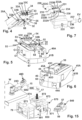
- FIG. 1 a perspective oblique view of a system according to the invention comprising a hand-held machine tool and a vacuum cleaner,
- FIG. 2 a partial view roughly corresponding to a detail D 1 of the vacuum cleaner according to FIG. 1 ,
- FIG. 3 a perspective oblique view of a communication module of the vacuum cleaner according to FIG. 1 ,
- FIG. 4 a device interface of a machine tool according to FIG. 1 ,
- FIG. 5 an energy storage module of the system according to FIG. 1 represented in a perspective oblique manner
- FIG. 6 the energy storage module according to FIG. 5 represented perspectively from another side
- FIG. 7 a charging device to charge the energy storage module according to FIGS. 5 , 6 ,
- FIG. 8 a communication module of the system according to FIG. 1 in a perspective oblique view
- FIG. 9 the communication module according to FIG. 8 , but with a fastening device for fastening on a schematically represented suction hose,
- FIG. 10 a schematic functional representation of the communication module according to FIG. 9 , 10 ,
- FIG. 11 a schematic circuit diagram of the energy storage module and a hand-held machine tool and a communication module according to FIG. 1 ,
- FIG. 12 a schematic circuit diagram of the energy storage module according to FIG. 4 in cooperation with the charging device according to FIG. 7 ,
- FIG. 13 a perspective representation of the other energy storage module according to FIG. 1 in the status put on the charging device according to FIG. 7 ,
- FIG. 14 a communication diagram between the vacuum cleaner according to FIG. 1 and an energy storage module
- FIG. 15 a schematically represented system with a vacuum cleaner arranged in a transport box and operable with an energy storage device
- FIG. 16 a diagram with a relation between signal strength information and a response time.
- a system 10 partially schematically represented in FIG. 1 comprises machine tools 20 A, 20 B which are supplied with electric energy by energy storage modules 40 A, 40 B.
- the machine tools 20 A, 20 B are machine tools generating dust or particles and in particular hand-held machine tools.
- the machine tool 20 B is for example a grinding device
- the machine tool 20 A is a saw, in particular a jigsaw, with a router or similar other electric machine tool or hand-held machine tool generating dust or particles also being readily possible.
- a drive motor 22 is arranged in a machine housing 21 A, 21 B of the machine tool 20 A, 20 B which is provided to drive a tool holder 23 A, 23 B and therefore a tool 38 A, 38 B arranged on the tool holder 23 A, 23 B.
- the tool 38 A is for example a sawing tool
- the tool 38 B is a grinding pad.
- the drive motor 22 can drive the tool 238 A, 38 B directly or via a gear, e.g. a gear 22 A for an oscillating movement.
- the machine tool 20 A, 20 B can be switched on and switched off using a switching element 24 , for example an on-switch/off-switch.
- a further switching element 25 is for example designed as a speed regulator or speed controller.
- An embodiment is possible in the case of which for example the speed of the drive motor 22 is modifiable by a corresponding actuation stroke of the switching element 24 .
- the hand-held machine tool 20 A, 20 B has a control device 26 to actuate the drive motor 22 .
- the control device 26 for example comprises a processor 27 and a memory 28 .
- a program module or a plurality of program modules 29 are stored in the storage device 27 , whose program code is executable by the processor 27 in order to control the hand-held machine tool 20 A, 20 B and/or to communicate with the energy storage modules 40 A, 40 B.
- the machine tool 20 A, 20 B has a suction connection or suction outlet 39 to connect a suction hose 15 via which dust occurring during the operation of the tool 38 A, 38 B can be suctioned.
- the suction outlet 39 for example a connection fitting, communicates with suction openings arranged on or in the tool 38 B, which are not visible in the drawing. Therefore, dust can be suctioned directly away from the tool 38 A, 38 B in a normal manner known per se.
- a vacuum cleaner 70 of the system 10 has a vacuum housing 71 which can be put and/or is rollable for example on rollers 71 A, 71 B on a floor.
- the vacuum device 70 is a mobile vacuum device.
- the vacuum cleaner 70 could, however, also have the shape of a stackable vacuum cleaner, consequently a stack housing and/or have a box shape.
- the rollers 71 A, 71 B are optional.
- the vacuum cleaner 70 has on the front side of the vacuum cleaner housing 71 a suction inlet 72 to which the suction hose 15 is connectable.
- the suction hose 15 extends with a longitudinal end 16 , which is connected to the suction outlet 39 A, and another longitudinal end 17 , which is connected to the suction inlet 72 , between the machine tool 20 A and the vacuum cleaner 70 .
- the machine tool 20 B is connected via a branch 18 of the suction hose 15 to the vacuum cleaner 70 .
- the branch 18 branches to the longitudinal end 16 and to a longitudinal end 19 which is connected to the suction outlet 39 A of the machine tool 20 B.
- the branch 18 of the suction hose 15 is optional.
- a suction hose can also be provided in a manner known per se which extends directly between a suction outlet 39 and the suction inlet 72 , without having a branch.
- a dirt collection chamber 73 is provided in the vacuum housing 71 in which dust and other particles can be received from a vacuum flow S, which is suctioned via the suction outlet 72 .
- a filter 74 is preferably provided above the dirt collection chamber 73 .
- a filter sack can also be arranged in the dirt collection chamber 73 in addition to or instead of the filter 74 which is suitable for collecting dirt and particles.
- the already mentioned vacuum flow S, which is suctioned through the suction inlet 72 can be generated by a suction unit 75 .
- the suction unit 75 is for example supplied with electric power using a mains connection device 76 .
- the mains connection device 76 for example comprises a connection cable and a connection plug to connect to an electric supply network EV, in particular with 220 V or 110 V alternating current.
- the functions of the vacuum cleaner 70 are controllable by an operating element arrangement 77 .
- the operating element arrangement comprises for example a switching element 78 , by means of which the vacuum cleaner can be switched on or switched off or switched into automatic operation, in the case of which for example a current guided via an outlet 79 leads to the suction unit 75 switching on and switching off.
- the outlet 79 is expediently provided on the operating element arrangement 77 .
- An electric consumer, preferably an electric hand-held machine tool 20 C can be connected in the outlet 79 .
- the outlet 79 has contacts 80 , in particular bushes into which contacts 32 C of a plug 31 C of the hand-held machine tool 20 C are insertable.
- the plug 31 C is arranged on a connection cable which is a part of a mains connection device 30 C. If an operator actuates a switching element 24 of the hand-held machine tool 20 C to power its drive motor 22 , with which for example a saw blade is drivable, current flows via the mains connection device 30 C, which is provided by the vacuum cleaner 70 via the outlet 79 . This current is detectable by a current sensor 81 in a manner known per se.
- a control device 86 of the vacuum cleaner 70 switches on the suction unit 75 in the case of a current flow via the outlet 79 in a manner known per se and at the end of the operation of the hand-held machine tool 20 C, i.e. when the current sensor 81 no longer determines a current flow, switches off the suction unit 25 , expediently with a stopping time.
- the current sensor 82 is for example connected to an input/output interface 82 of the control device 80 .
- the input/output interface 82 for example a power electronics interface further serves to actuate the suction unit 75 .
- the control device 86 further has a processor 87 and a memory 88 in which one or a plurality of program modules 89 are stored.
- the at least one program module 89 has a program code which is executable by the processor 87 and, amongst other things, enables one or a plurality of the following functions.
- the outlet 79 is connectable via the vacuum cleaner 70 to the supply network EV or also connectable directly to the supply network EV, namely using the mains connection device 30 C.
- the machine tools 20 A, 20 C in contrast are equipped for a cableless or wireless operation. They can namely be supplied with electric power using the energy storage modules 40 A, 40 B.
- the energy storage modules 40 A, 40 B are constructed functionally similarly, with mechanical differences and/or electric differences possibly readily existing with regards to the power supply capacity, voltage or the like.
- the energy storage modules 40 A, 40 B have module housings 41 A, 41 B in which energy storage devices 42 are arranged.
- the energy storage devices 42 have one or a plurality of storage cells 43 , in particular a storage cell arrangement with a plurality of storage cells 43 which are rechargeable.
- a charge status of the energy storage device 42 can be output, for example acoustically and/or optically.
- the display device 44 for example comprises a speaker 44 A, which can signal a low charge status, e.g. using a warning tone.
- an arrangement of one or a plurality of lights 45 is preferred, for example lights 45 A, 45 B, 45 C and 45 D.
- the lights 45 A- 45 D are preferably LEDs.
- the functions of the energy storage modules 40 A, 40 B are controllable by control devices 46 .
- the control devices 46 can be supplied with electric energy directly by the energy storage device 42 and/or one or a plurality of the storage cells 43 .
- supply lines 42 X can be provided between the energy storage device 42 and the control device 46 .
- a control device 46 can also have a supply module 46 X to adapt a voltage provided by the energy storage device 42 or a supply current provided by the energy storage device 42 . Therefore, a respective control device 46 can be supplied with electric energy locally, irrespective of whether the energy storage module 40 is connected to an electric device, for example a charging device or a machine tool or a vacuum cleaner.
- the control devices 46 for example have a processor 47 and a memory 48 in which at least one program module 49 is stored.
- the control device 46 can communicate with the control device 26 of the hand-held machine tool 20 A, 20 B.
- the processor 47 can execute program code of the program modules 49 , amongst other things to implement the functions explained in detail below.
- the energy storage modules 40 A, 40 B are detachably connectable to one another with the machine tools 20 A, 20 B using device interfaces 30 of the machine tools 20 A, 20 B and device interfaces 50 of the energy storage modules 40 A, 40 B.
- the machine tools 20 A, 20 B form first system components 11 , the energy storage modules 40 A, 40 B second system components 12 , which are fixedly connected to one another such that they in each case form a system.
- the device interfaces 30 , 50 comprise, to this end, contours fitting together in a positive-locking manner, for example to form positive-locking contours suitable for rotary locking or as in the present case plug positive-locking contours 51 on the device interface 50 , which can engage the device interfaces 30 in a positive-locking manner with plug counter positive-locking contours 31 , namely in the context of a plug movement.
- device supply contacts 32 of the device interface 30 enter into contact with supply contacts 52 of the device interface 50 such that electric energy from the energy storage device 42 can be provided via the supply contacts 52 , 32 for the respective machine tool 20 A, 20 B, in particular its drive motor 22 .
- the device interfaces 30 , 50 further comprise data contacts 33 , 53 of data interfaces 34 , 54 such that even data communication, in the present case in particular a bus communication between the system components 11 , 12 , is possible.
- a fixing device 55 provides additional hold for the positive-locking design using the plug positive-locking contours 51 , 31 by means of which the system components 11 , 12 are fixable to one another.
- the fixing device 55 for example comprises a fixing element 56 , in particular a catch, a latching element or the like which can be engaged with a fixing contour 35 .
- the fixing contour 35 and the fixing element 56 are arranged on the first system components 11 and the second system components 12 , with the reverse configuration also being readily possible.
- the fixing device 55 forms, in the present case, a locking device and/or catch device.
- the fixing element 56 can, using an actuation element 57 , be disengaged, optionally also engaged, with the fixing contour 35 .
- the fixing element 56 is a fixing projection/locking projection, which can be engaged with the fixing contour 35 designed as a fixing holder or depression. If the fixing device 55 engages its fixing position or locking position, the plug positive-locking contours 51 remain engaged with the plug counter positive-locking contours 31 , i.e. a relative movement of the system components 11 , 12 along the plug axis of the plug positive-locking contours 51 , 31 is not possible.
- the actuation element 57 and/or the fixing element 56 are spring-loaded by a spring arrangement (not visible) into the fixing position or locking position. Therefore, the fixing device 55 can be moved out of the fixing position into the detached position by simple pressure actuation or button actuation of the actuation element 57 .
- one fixing element 56 is preferably provided on the energy storage module 40 A on sides opposed to one another, also in each case one actuation element 57 is necessary, while in the case of the energy storage module 40 B only a single push button or a single actuation element 57 is necessary.
- the energy storage modules 40 A, 40 B can be charged using a charging device 220 .
- the charging device 220 has a charging device housing 221 on which a device interface 230 is provided.
- the device interface 230 has plug counter positive-locking contours 231 which are compatible in a positive-locking manner with the plug positive-locking contours 51 of the energy storage modules 40 A, 40 B. Locking is not necessary for stationary operation.
- the charging device 220 further has device supply contacts 232 and data contacts 233 of a data interface 234 , preferably a bus interface.
- a voltage transformer 235 is preferably arranged in the charging device 220 , which can be supplied with electric power using a mains connection device 236 and provide a direct voltage at the device supply contacts 232 to charge the energy storage device 42 .
- the connection plug 237 forms a part of a mains connection device 236 and can be arranged directly on the charging device housing 221 or be connected via a line, which is schematically represented, to the charging device housing 221 .
- the connection plug 237 is connectable to the supply network EV.
- the data interfaces 34 , 54 and 234 are bus interfaces in the present case.
- the bus interfaces or data interfaces 34 , 54 , 234 are I 2 C bus interfaces.
- the bus interfaces comprise a clock line CL, a data line D and a supply line VD, to which data contacts 33 A, 53 A and 234 A are assigned, a clock line CL, to which data contacts 33 B, 53 B and 233 B are assigned, and a data line D, to which data contacts 33 C, 53 C, 234 C are assigned.
- the supply line VD is used so that the device interface 30 or 230 of the device interface 50 provides an electric supply voltage, for example a bus voltage UB.
- a bus clock of the bus BU implemented on the data interfaces 34 , 54 , 234 is provided via the clock line CL.
- Data is transferred via the data line D, preferably bidirectionally from the energy storage module 40 to the machine tool 20 and vice versa and/or from the energy storage module 40 to the charging device 220 and vice versa.
- the energy storage module 40 provides a supply voltage UV to the supply contacts 52 A, 52 B which is suitable for operating the drive motor 22 .
- the supply voltage UV is for example a direct voltage of 15 volts or 18 volts, but can also be another voltage at any time. It should be mentioned at this point that an energy supply module could of course also provide an alternating voltage. This is not essential.
- the control device 26 of the machine tool 20 A, 20 B simply designated below as the machine tool 20 , actuates, as a function of an actuation of the switching element 24 , the drive motor 22 , with it opening or closing for example a switch 24 A.
- a power electronics for example an energisation device can also be provided for an electronically commuted drive motor 22 .
- the switching element 24 it is conceivable for the switching element 24 to be switched directly into the current circuit of the drive motor 22 and therefore to be able to switch it on and off. If the switch 24 A is closed, the current flows from the energy storage device 42 via a line L 1 to the drive motor 22 and from said drive motor back via a line L 2 to the energy storage device 42 .
- a charging current IL flows in this case from the voltage transformer 235 via the line L 1 to the energy storage device 42 .
- the supply contact 232 B is, just like the supply contact 52 , assigned to a line L 2 , for example to an earth line.
- the charging operation is preferably controlled by a control device 226 of the charging device 220 .
- the control device 226 can for example actuate the switch 238 in order to begin or end the charging operation.
- the charging device 220 In order to monitor the charging operation, the charging device 220 also communicates with the energy storage module 40 , namely via the data interface 234 and the data contacts 233 A, 233 B and 233 C assigned thereto for the supply line VD, the clock line CL and the data line D.
- the charge status of the energy storage device 42 can for example be requested by corresponding communication on the bus BU between the charging device 220 and the energy storage module 40 .
- the charging device 234 has for example a processor 27 which can execute control commands or program code of a program module 229 to control the charging operation.
- the processor 227 is connected to a memory 228 of the control device 226 of the charging device 220 in which the program module 229 is stored.
- the vacuum cleaner 70 is actuatable in a wireless or cableless manner.
- the vacuum cleaner 70 has an integral external communication apparatus 100 or an external communication apparatus 100 preferably designed as a module.
- the external communication apparatus 100 is detachably arrangeable in a module holder 90 of the vacuum cleaner housing 71 .
- the module holder 90 is for example arranged in the region of the operating element arrangement 77 , in particular a front wall 95 on which the operating element arrangement 77 is provided.
- the control device 86 supplies the external communication apparatus 100 with the electric supply voltage via the contact arrangement.
- a data interface 83 of the control device 86 and a data interface 108 of the external communication apparatus 100 are in contact with one another using the contact arrangements 101 and 91 .
- the data interfaces 83 , 108 for example comprise a bus interface, via which the external communication apparatus 100 and the control device 86 can communicate data and information.
- the data interfaces 108 , 83 for example implement a bus connection, in particular an I 2 C bus connection. Other bus communications are also possible. Furthermore, the data interfaces 83 , 108 can also comprise individual data contacts, for example for a parallel data transmission.
- the module holder 90 comprises side walls 92 which extend from a bottom 93 of the module holder 90 to the front wall 50 .
- the contact arrangement 101 protruding from a rear side 103 of a front wall 105 of the external communication apparatus 100 can engage into the contact arrangement 91 arranged on the bottom 93 of the module holder 90 or enter into contact therewith.
- Side wall surfaces 101 of the front wall 105 are then aligned with the side walls 92 such that a forward side or the front wall 105 of the external communication apparatus 100 , as represented in FIG. 1 , is aligned with the front wall 95 .
- the plug connection of the module of the external communication apparatus 100 in the module holder 90 alone ensures a reliable hold.
- a fixing device for example a catch device, clamp device or the like not represented in the drawing is preferably provided for further fixing.
- a screw connection is provided.
- one or two screw holders 94 are provided on the module holder 90 which align with screw holders 104 of the external communication apparatus 100 when this is received in the module holder 90 . Screws indicated in FIG. 1 can be screwed into the screw holders 104 , 94 .
- the vacuum cleaner 70 can be actuated in a wireless and/or cableless manner using the external communication apparatus 100 , for example by a wireless communication interface 60 of the energy storage module 40 A or 40 B.
- the wireless communication interface 60 is to be provided by way of example for a wireless actuation of the systems comprising the system components 11 and 12 , namely in each case an energy storage module and a machine tool.
- the machine tool 20 C can for example be equipped with a wireless communication interface 60 C in order to directly perform one or a plurality of communication functions still to be described below, i.e. without a respective energy storage module 40 , which a wireless communication interface, communicating wirelessly with the vacuum cleaner 70 .
- the external communication apparatus 100 can be switched, using a registration operating element 160 , into a standby mode from an operating mode in which a control connection with the external communication apparatus 100 can be newly established or re-established.
- the standby mode or the operating mode are optically and/or acoustically signalled by the external communication apparatus 100 .
- a display device 114 is provided which can signal different operating modes of the external communication device 100 .
- the display device 114 for example comprises a light display, in particular a circular light display.
- the display device 114 is for example arranged around or on the registration operating element 106 .
- the registration operating element 106 is for example a button 107 around which the display device 114 preferably circularly extends.
- the display device 114 When the display device 114 permanently illuminates, it signals an established control connection, i.e. the status “connected”.
- the display device 114 When the external communication apparatus 100 is switched, using the registration operating element 106 , from the operating mode into the standby mode, the display device 114 illuminates for example in another colour or with another movement pattern, in particular with a slow, circulating movement pattern. This movement pattern or the colour of the display device 114 can be independent on the type of control connection.
- a control connection as explained below, is a control connection to be currently established and/or a temporary control connection already established, the display device 114 can for example have a slow circulating light display.
- the standby mode is suitable for establishing a permanent control connection
- the display device 114 illuminates differently. For example, the circular illumination of the display device 114 then takes place at a higher frequency.
- a e.g. communication module 300 is provided, which preferably forms a system component of the vacuum cleaner 70 , is connected to the external communication apparatus 100 .
- the communication module 300 is a communication module arranged or arrangeable outside of the vacuum housing 71 .
- the communication module 100 serves to maintain and/or establish a control connection of the electric device in the shape of the system components 11 and/or 12 with the vacuum cleaner 70 , in particular the external communication apparatus 100 .
- the communication module 300 has a module housing 301 which can be placed on the suction hose 15 .
- the module housing 301 expediently has on its upper side 302 a switching element 334 with which the suction unit 75 can be switched on and/or off.
- the switching element 334 takes up the majority of the upper side 302 in an ergonomically favourable manner such that it is easy to operate or actuate.
- the switching element 334 is for example a push button, rocker switch or the like.
- the module housing 301 has a shape adapted to the suction hose 15 .
- an underside wall 306 which, in the status of the communication module 300 installed on the suction hose 15 , comes to rest on its outer circumference, has a round contour adapted to the round outer circumference of the suction hose 15 .
- a forward side wall 303 , a rear side wall 304 and longitudinal side walls 305 extend between the underside wall 306 and the upper side or upper side wall 302 . They delimit an internal space in which a control device 336 of the communication module 300 is arranged in a supported manner.
- the control device 336 for example has a processor 337 , a memory 338 and at least one program module 339 which comprises program code which can be executed by the processor 337 to perform the functions of the communication module 330 , which will be explained later.
- hooks 301 are provided on the longitudinal side walls 305 . Consequently, the module housing 301 thus has in each case one hook 307 at sides opposed to one another. Each hook 307 has a hook projection 308 and a hook depression 309 .
- the hooks 307 serve to fasten a hose bracket 320 ( FIG. 8 ) for example of a clamping point 321 .
- the hose bracket 320 has on its longitudinal end regions 322 in each case hook holders 323 which can be engaged with the hooks 307 .
- other fastening technologies are also possible, for example by means of an adhesive strip or the like.
- a communication module 300 on the longitudinal ends 16 and/or 17 of the suction hose 15 may also be conceivable, for example when corresponding tubular bodies are provided, e.g. connection pieces or connection fittings made from rubber, plastic or the like.
- the communication module 300 can, however, also be adhered, welded on the suction hose 15 or similarly otherwise connected to the suction hose 15 . However, this is irrelevant for the communication functions of the communication module 300 .
- the ergonomically favourable arrangement on the suction hose 15 is also advantageous.
- a registration operating element 316 is provided.
- the registration operating element 316 for example comprises a button 317 .
- the functions of the registration operating element 316 correspond to those of the registration operating element 106 such that the operator so to speak finds the same operating design.
- a display device 314 is also designed identically or similar to the display device 114 .
- the display device 314 for example comprises a light display which signals information in relation to the establishment and/or presence of a control connection between the communication module 300 and the external communication apparatus 100 .
- a communication interface 311 in particular a Bluetooth interface, a WLAN interface or the like sends a corresponding control signal, in particular a switching message SN to the communication interface 110 to switch to the standby mode.
- the external communication apparatus 110 is switched to a standby mode which the display device 314 signals.
- An actuation of the registration operating element 316 leads to the external communication apparatus 100 switching from the operating mode to the standby mode.
- an encrypted and/or authenticated connection is preferably provided between the communication module 300 and the external communication interface 110 .
- the communication module 300 When the switching element 334 is actuated, the communication module 300 sends a start command or switch-on command for the suction unit 75 to the external communication apparatus 100 and consequently to the control device 86 of the vacuum cleaner 70 .
- the communication module 300 can send a control command to the external communication device 100 and therefore to the vacuum cleaner 70 , with which for example the speed of the suction unit 75 and/or its power can be adjusted. Consequently, the communication module 300 can serve as a remote control for the suction unit 75 .
- a secured and/or encrypted control connection between the communication module 300 and the external communication apparatus 100 is also advantageous for the remote control functions.
- a control connection from the communication module 300 to the external communication apparatus 100 is a so to speak permanent control connection.
- Such a control connection requires a higher degree of difficulty to establish it than a control connection between a system component 11 or 12 and the vacuum cleaner 70 .
- the registration operating element 106 and/or 316 must be actuated for longer in order to authorise or register the communication module 300 at the vacuum cleaner 70 or the external communication apparatus 100 .
- a registration procedure to establish a control connection between one of the system components 11 or 12 for example the energy storage module 40 and the external communication apparatus 100 is, in contrast, easier to establish, for example using a shorter actuation of the registration operating element 106 and/or 316 .
- the machine tools 20 A, 20 B communicate using the energy storage modules 40 A, 40 B with the vacuum cleaner 70 and can actuate it via control connections S 1 and S 2 .
- control commands cannot be sent directly via the control connections S 1 , S 2 , but rather only after a previous registration/authorisation of the machine tools 20 A, 20 B at the external communication apparatus 100 . Consequently, the respective control connection S 1 , S 2 must firstly be established before it is available for the transmission of control commands and/or status signals between the components 20 A, 70 or 20 B, 70 remote from one another.
- the configuration is in this case made such that the machine tools 20 A, 20 B do not communicate directly wirelessly with the vacuum cleaner 70 , but rather using the energy storage modules 40 A, 40 B assigned to them and attached to them.
- the communication described below in relation to the wireless communication interface 60 is also implementable with a at the machine tool 20 B, namely for example directly (not represented), similar to the control connection S 2 or indirectly via the communication modules 300 B and 300 C, as will be clearer.
- the energy storage modules 40 A, 40 B form so to speak gateways for the machine tools 20 A, 20 B for wireless communication, in particular in the control direction, i.e. from the machine tool 20 A, 20 B to the vacuum cleaner 70 .
- the reverse communication direction from the vacuum cleaner 70 to the machine tools 20 A, 20 B is also possible via the gateways 40 A, 40 B.
- the energy storage modules 20 A, 20 B are smart such that they can identify for example whether they are connected to a device requiring wireless communication with the vacuum cleaner 70 or a device even implementing such communication or to another device, for example a machine tool, which is not suitable for the vacuum cleaner operation, for example a screwing device, a gluer or the like.
- the energy storage modules 40 A, 40 B can detect whether they are connected to the charging device 220 .
- the charging device 220 sends, namely for example via the bus interface BU, a request message 700 to the control device 46 with which it requests the current charge status of the energy storage device 42 , the status and/or the maximum charge voltage for the storage cells 43 , maximum charging currents or the like.
- the control device 46 responds with a response message 701 in which the corresponding information is stored.
- the energy storage module 40 identifies that it is connected to a charging device and not to an electric consumer in the manner of the machine tool 20 A or 20 B which requires a wireless communication connection to a vacuum cleaner.
- a charging voltage UL which is provided by the charging device 220
- a supply voltage UV which is applied at the connection of an electric consumer between the lines L 1 and L 2 or the supply contacts 52 A, 52 B.
- the control device 46 is supplied with electric energy via the bus interface or data interface 54 .
- the supply voltage UB 2 applied at the supply line VD or the data contact 53 A, which is provided by the charging device 220 differs in its voltage level from the supply voltage UB 1 , which the electric hand-held machine tool 220 provides at the data contact 53 A.
- the supply voltage UB 1 is for example 3 volts, the supply voltage UB 2 5 volts.
- a voltage measuring device 61 in particular a voltage sensor, resistance circuitry or the like is provided at the data interface 54 to detect the different voltage levels of the voltages UB 1 and UB 2 such that the control device 46 can identify whether it is connected to a charging device (charging device 220 ) or to an electric consumer or an electric machine tool in the manner of the machine tools 20 A, 20 B.
- a charging device charging device 220
- an electric consumer or an electric machine tool in the manner of the machine tools 20 A, 20 B.
- control device 46 depending on whether the energy storage module 40 is connected to a machine tool 20 or to the charging device 220 , changes an operating mode of the wireless communication interface 60 .
- the control device 46 activates the wireless communication interface 60 when the energy storage module 40 is connected to a machine tool 20 , while it deactivates the wireless communication interface 60 when the energy storage module 40 is connected to the charging device 220 .
- the control device 46 does not deactivate the wireless communication interface 60 , when the energy storage module 40 is connected to a machine tool 220 , but changes the communication mode.
- the wireless communication interface 60 can for example remain active for communication with the configuration device 500 still to be explained, in particular a smartphone when the energy storage module 40 is not connected to the machine tool 20 , for example is connected to the charging device 220 or has no such connection.
- the configuration device 500 for example the smartphone, program data or the like can for example be transmitted to the energy storage module 40 , even if this is not connected to the machine tool 20 .
- the energy storage module 40 A or 40 B is connected to the machine tool 20 A or 20 B, the wireless communication with the vacuum cleaner 70 , in particular its external communication apparatus 100 is easily possible without problems.
- a function and communication process 400 begins for example with an operating action 401 of an operator N.
- the operator N of the system 10 connects for example the vacuum cleaner 70 to the supply network EV or actuates the switch or the switching element 78 such that the vacuum cleaner is essentially operationally ready, i.e. has a function 410 “status in operation”.
- a control device 117 of the external communication apparatus 100 switches at this point into a status 411 in which the external communication apparatus searches for devices already authorised to actuate the vacuum cleaner 70 .
- This status 411 lasts for example a predetermined time, in particular one minute or two minutes, after which it ends once again. This time limitation is an option that reduces the risk of unauthorised access to the vacuum cleaner 70 .
- control device 116 has for example a processor 117 to execute the program code of a program module 119 which is stored in a memory 118 of the external communication apparatus 100 .
- a function 412 of the program module 119 enables for example the detection of information of the registration operating element 106 .
- the registration operating element reports the function 412 using an output command 414 to the operator N by it namely actuating the display device 114 such that the operator sees that the external communication apparatus 100 and therefore the vacuum cleaner 70 is ready to establish new control connections.
- the external communication apparatus 100 goes into a status 415 , namely into an operation standby mode in which a control connection can be established with the external configuration apparatus 100 .
- the communication module 40 is thus inactive at the start of the function and communication process 400 in a status 430 “sleep”. Proceeding therefrom, a number of scenarios are possible to establish one of the control connections S 1 or S 2 , of which a first scenario is described below:
- the operator N actuates for example the switching element 24 of the machine tool 20 A in order to switch it on.
- the machine tool 20 A or the assigned energy storage module 40 A is still, however, not authorised to output switching commands or control commands to switch on the suction unit 75 .
- Such a registration or authorisation occurs automatically so to speak when the operator N simply actuates the switching element 24 .
- each of the energy storage modules 40 A, 40 B identifies from operational information coming from the actuation of the switching element 24 that a device suitable for establishing and using a control connection is connected to the device interface 50 .
- the energy storage module 40 can thus for example identify using the supply voltage UV that an electric consumer is connected.
- the voltage UV differs from the voltage UL of the charging device 220 .
- Further operational information can for example also be the supply voltage UB 1 which is provided by the control device 26 to the supply line VD or the data contact 53 a .
- the supply voltage UB 1 differs from the supply voltage UB 2 of the charging device 220 , it is in particular lower than it. Therefore, the supply voltage UB 1 thus also forms an indicator of an actuation of the switching element 24 .
- an initialisation communication can be evaluated on the bus BU from the control device 46 as an indicator of the activation of the data interface 54 by a device actuating the vacuum cleaner 70 , i.e. the machine tool 20 A or 20 B (designated below only as machine tool 20 ).
- a request message 750 can be sent from the control device 26 to the control device 46 , with which for example a supply voltage UV of the energy storage module 40 , which can be provided, is queried.
- data identifying the electric device or the machine tool 20 may be contained, for example an identifier 751 which characterises the machine tool 20 A, 20 B as a machine tool requiring dust extraction.
- the request message 750 for example represents operationally ready information of the machine tool 20 .
- the control device 46 responds to the request message 750 and provides the requested information and/or information, for example charge status of the energy storage module etc.
- the energy storage module 40 sends via the wireless communication interface 60 in a function 431 , for example the program module 419 , in the context of a transmission operation 432 , a registration message 440 to the external communication apparatus 100 .
- the registration message 440 comprises for example a broadcast transmission identifier 44 x , i.e. a registration message, which is directed to a plurality of essentially ready-to-receive vacuum cleaners, not only the vacuum cleaner 70 .
- an authorisation parameter 442 is optionally indicated in the registration message 440 .
- the authorisation parameter 442 comprises for example an essential system compatibility of the energy storage module 40 or the machine tool 20 with the vacuum cleaner 70 .
- the authorisation parameter 442 can for example comprise a manufacturer identifier or the like.
- the external communication apparatus 100 receives the registration message 440 with a function 416 .
- the function 416 is active for a predetermined time period, for example 500 msec to 1000 msec because in this time the registration procedure must be concluded with the registering energy storage module 40 .
- the external communication apparatus 100 confirms the registration of the energy storage module 40 .
- the registration confirmation message 445 is sent in a step or transmission operation 417 .
- the registration confirmation message 445 comprises for example the address identifier 446 of the energy storage module 40 as the sender address.
- further information 447 can be contained in the registration confirmation message 445 , for example an access key, a password or the like.
- the information 447 can, however, also for example identify a suction power of the suction unit 75 that is required or to be set or other similar information favourable to the subsequent operation.
- the registration of the energy storage module 40 at the external communication apparatus 100 is, however, only a temporary registration which is necessary for a current operation. Accordingly, a temporary identifier 443 is advantageously contained in the registration message 440 such that the external communication apparatus 100 knows so to speak that only a temporary registration or temporary control connection is desired.
- the communication module 300 does not indicate in a registration message comparable with the registration message 440 the temporary identifier 443 , but rather a permanent identifier.
- the function 431 advantageously comprises a time limitation. If a registration confirmation message 445 does not arrive within a predetermined or settable time, for example 500 to 1000 msec after switching on the switching element 24 and/or after sending the registration message 440 , the registration attempt fails so to speak.
- the external communication apparatus 100 transmits with an encryption parameter 451 .
- the external communication apparatus 100 uses the already existing parameters.
- the address identifier 446 and assigned thereto the encryption parameter 451 of an already previously existing control connection to the energy storage module 40 A, 40 B are stored in the memory 118 of the external communication apparatus.
- address identifiers and assigned encryption parameters can also be stored in the memory 118 , for example an address identifier 446 C of the wireless communication interface 60 C and an encryption parameter 451 C for a control connection between the wireless communication interface 60 C of the machine tool 20 B and the external communication apparatus 100 .
- the external communication apparatus 100 when encryption parameters for the respective energy storage module 40 are not known, sends, using a message 455 , the encryption parameter 451 or a new, different encryption parameter 456 such that an encrypted communication between the components 100 , 40 is possible and therefore the status 421 “encrypted connection” is achieved.
- the external communication apparatus 100 controls the display device 114 (step 423 A) such that it signals the available, encrypted connection.
- the display device 114 then permanently illuminates.
- a plurality of address identifiers and/or encryption parameters are stored at an energy storage module.
- provision can be made for it to have stored address data and encryption data of a further vacuum cleaner not represented in the drawing, namely for example an address identifier 441 B and an encryption parameter 451 B of this further vacuum cleaner. Therefore, the energy storage module 40 can also, if required, so to speak access other vacuum cleaners directly.
- the energy storage module 40 sends in a transmission operation 434 for example the control device 46 for example a control command 460 which contains a switch-on identifier 461 .
- the control device 46 activates in an activation step 435 the display device 44 to display the established control connection S 1 or S 2 .
- the lights 445 illuminate blue or in a pattern different to the display of a charge status.
- the external communication apparatus 100 After receiving the control command 460 , the external communication apparatus 100 for example actuates the control device 86 such that it switches on the suction unit 75 in a step 422 .
- the external communication apparatus 100 in particular its control device 116 , controls the display device 114 (step 423 ) such that it signals the switching-on of the suction unit 75 .
- the display device 114 then permanently illuminates.
- the control device 46 can detect this, for example using a corresponding current sensor 62 .
- the supply voltage or bus voltage UB 1 is in this case also lower or smaller.
- the energy storage module 40 actively sends the data interfaces or bus interfaces 34 , 54 a message 753 “motor switched off”.
- a function 436 “switch off” of the energy storage module 40 .
- a switch-off identifier 463 for example a stopping time for the vacuum cleaner 70 or the suction unit 75 is indicated.
- the request message 750 and the message 753 form received information EM, which the energy storage module 40 receives at the data interface 54 , in order to output namely for example the registration message 440 to the wireless communication interface 60 as a function of transmission signals SII.
- the response message 445 is for example a received signal ESI, using which the energy storage module 40 outputs the response message 752 to the data interface 54 as transmission information SM.
- a function 427 “switch off”, the communication apparatus 100 actuates, directly or actuating the control device 86 , the suction unit 75 to switch off and the display device 114 to display the ended actuation.
- the function 427 gives an actuation command 425 to the suction unit 75 directly or via the control device 86 , namely the data interfaces 83 and 108 .
- the energy storage module 40 can send further subsequent control commands 460 and 462 in order to switch on and switch off the suction unit 75 .
- the energy storage module 40 in contrast goes into a status 439 , namely a status “sleep”, corresponding to the status 430 .
- the function 436 expediently outputs this new operating status to the display device 44 , for example by the display device 44 being actuated using an actuation in a deactivation step 438 to signal the ended control connection.
- the lights 45 then for example no longer illuminate blue, but rather green and signal the charge status of the energy storage device 42 .
- the machine tool 20 sends a configuration message 754 via the bus BU to the energy storage module 40 .
- configuration data 755 is indicated to set the vacuum cleaner 70 , for example a required suction power of the suction unit 75 , a typical particle amount in the dust generated by the machine tool 20 etc.
- the energy storage module 40 preferably provides this data via the wireless communication interface 60 to the external communication apparatus 100 to configure the vacuum cleaner 70 , for example as configuration message 465 .
- the external communication apparatus 100 provides the configuration data 755 to the control device 86 to further process, in particular suitably actuate the suction unit 75 , e.g. using a transmission operation 437 ′.
- control device 86 and/or the external communication apparatus 100 it is preferred for the control device 86 and/or the external communication apparatus 100 to permanently store the configuration data 755 and assign it to the respective machine tool 20 A and 20 B, for example in the memory 88 and/or 118 . Furthermore, it is advantageous for an operator to be able to override the stored configuration so to speak, for example by an actuation of the operating element arrangement 77 . Thus, for example a suction power of the suction unit 75 can be set at a switching element 78 A.
- suction parameters set directly by an operator at the vacuum cleaner are permanently stored by the control device 86 and/or the external communication apparatus 100 and assigned to the respective machine tool 20 A and 20 B, for example in the memory 88 and/or 118 when the vacuum cleaner is currently actuated by the respective machine tool, for example one of the machine tools 20 A or 20 B.
- the configuration data 755 or suction parameters it is possible, however not absolutely necessary, for the configuration data 755 or suction parameters to be sent wirelessly by the machine tool 20 A or 20 B.
- Establishing a control connection can, however, also take place automatically so to speak when an energy storage module 40 and a machine tool 20 are connected together. This is explained below by way of example of one of the energy storage modules 40 . However, it is also possible that for example the wireless communication interface 60 C in this manner so to speak automatically establishes a respective control connection to the vacuum cleaner 70 or the external communication apparatus 100 when the energy supply is so to speak started by the energy storage module 40 or is arranged on the device interface 30 .
- the energy storage module 40 and/or the machine tool 20 can have capacity sensors 66 , 36 with which capacities C 1 and C 2 between the supply contacts 32 A, 32 B or 52 A, 52 B can be measured.
- the capacitive relationships change namely between the lines L 1 and L 2 thus at the energy-supplying contacts or the energy-supplying lines when a respective energy storage module 40 is fastened to a machine tool 20 .
- the sensors 36 , 66 are connected with the control devices 26 , 46 or communicate therewith.
- the control device 46 when the sensor 66 identifies that the machine tool 20 is connected, i.e. an operating status is achieved, can automatically send the registration message 440 .
- At least one verification message in particular provided exclusively to verify the operating status or separation status can be provided to a data interface, for example the bus interface BU.
- a type of ping message can be provided for this purpose.
- the processor 27 and/or a processor 27 A of the machine tool 20 or of the charging device 220 provided especially for the mentioned purpose can in particular cyclically send a verification message CK, using which the energy storage module 40 identifies for example that it is connected to the machine tool 20 or the charging device 220 or that there is no connection to such a device.
- the processor 47 or a processor 47 A provided especially for this message is present at the energy storage module 40 .
- the processor 47 and/or 47 A can send as the response to the verification message CK for example a response message RP.
- a sensor 58 can sense an actuation of the actuation element 57 of the fixing device 55 .
- the energy storage module 40 in particular the wireless communication interface 60 can in this case for example automatically end the control connection S 1 or S 2 .
- the wireless communication interface 60 for example sends a corresponding separation command or a separation message. It is particularly preferred when, through actuation of the actuation element 57 , also the vacuum cleaner 70 can also be switched off because the components 20 and 40 are separated from one another.
- the control device 46 sends the control command 462 when the actuation element 57 is actuated, which can be detected by the sensor 58 .
- one or a plurality of motion sensors are provided, namely for example a motion sensor 59 at the energy storage module 40 and a motion sensor 59 B at the machine tool 20 .
- the control devices 46 , 26 can communicate this to one another and as a result identify that the energy storage device 40 and the machine tool 20 are in the operating status, i.e. in the status fastened to one another.
- an optical sensor 68 or another proximity sensor detects when the device interface 30 is fastened to the device interface 50 .
- the optical sensor or proximity sensor 68 is for example marked on the energy storage module 40 A according to FIG. 5 , but could readily also be provided on the device interface 30 of the machine tool 20 (see FIG. 4 ).
- an electric switch 68 in particular a push button or press button is also actuated when the plug positive-locking contours 51 and 31 are engaged with one another, i.e. when the device interfaces 30 , 50 are mechanically connected to one another.
- the electric switch 69 can also therefore distinguish the operating status from the separation status of the device interfaces 30 , 50 and lead to the wireless communication interface 60 C or the energy storage module 40 sending the registration message 440 .
- the energy storage module 40 receives in the context of the received information EM at least one status information item, in particular error information and/or switching position of a switch, of the electric device and/or at least one identification information item, for example a serial number of the electric device.
- the energy storage module 40 can receive error information as status information 29 C and identification information 29 D for example a unique identifier or a serial number of the machine tool 20 , from the machine tool 20 .
- the machine tool 20 sends this received information EM spontaneously via the data interface 54 , i.e. without previous request by the energy storage module 40 at the machine tool 20 or that the energy storage module 40 requests this received information EM at the machine tool 20 .
- the error information can for example represent overheating or electric overloading of the machine tool 20 .
- the identification information 29 D can also comprise a type identifier, so that for example the type of machine tool 20 , in particular screwing device, sawing machine or the like can be identified using the identification information 29 D.
- the aforementioned received information EM is for example not security-related or to be kept secret.
- the energy storage module 40 it is advantageous for the energy storage module 40 to send, in particular encrypted, this received information EM in the context of a broadcast communication or advertising communication cyclically or periodically and/or at the transition from the separation status to the operating status, i.e. in the case of connection to the machine tool 20 .
- encrypted communication can also take place when for example encryption parameters are already exchanged between the energy storage module 40 and the configuration apparatus 500 or another receiving device.
- the configuration apparatus 500 can receive the identification information 29 D and/or the status information 29 C from the energy storage module 40 .
- the vacuum cleaner 70 can, as explained, have one or a plurality of communication modules 300 .
- the arrangement with a plurality of configuration modules 300 A, 300 B and 300 C is optional, i.e. only one of these communication modules could for example be provided or even none of them.
- the vacuum cleaner 70 would still function.
- the communication modules 300 A can be used using their communication interfaces 311 to maintain or establish a control connection.
- a control connection S 6 can be established by the hand-held machine tool 20 B or the energy storage module 40 B to the vacuum cleaner 70 or the external communication apparatus 100 , which is established and/or maintained at least partially by the communication module 300 B and 300 C.
- the wireless communication interface 60 C of the machine tool 20 A or the wireless communication interface 60 of the energy storage module 40 B can communicate on a section S 61 firstly with the communication module 300 , for example in order to send the control command 460 and/or 462 , i.e. to switch on and switch off the suction unit 75 .
- the communication module 300 communicates this information or this control command to the communication module 300 B which in turn provides the received control command or the received information on a connection section S 63 to the external communication apparatus 100 or the vacuum cleaner 70 .
- the connection sections S 61 and S 63 are short. Accordingly, the transmission power of the external communication apparatus 100 and of the wireless communication interface 60 / 60 C can be particularly low.
- the receiving ranges of the communication modules 300 B and 300 C can be designed short such that interrupting information of a third party or an interrupting control command is not even received and provided by the communication modules 300 B and 330 C.
- the communication modules 300 B and 300 C can also provide information sent by the vacuum cleaner 70 to the energy storage module 40 B or the machine tool 20 B, i.e. they can operate unidirectionally either from the vacuum cleaner to the machine tool or vice versa from the machine tool to the vacuum cleaner or even bidirectionally.
- the gateway function is expediently bidirectional.
- the vacuum cleaner 70 can for example communicate via the control connection S 6 , which is in this case a reporting connection, for example a fill level of the dirt collection chamber 73 such that the machine tool 20 B possibly adjusts its operation when dust discharge is no longer possible.
- the communication modules 300 A and 300 B can also readily in this manner implement a gateway function in relation to the machine tool 22 A and the vacuum cleaner 70 .
- a communication module 300 for example the communication module 300 A serves as a gateway between the external communication apparatus 100 and the energy storage module 40 A.
- the communication modules can also assist with establishing communication relations and in particular control connections. Furthermore, a communication module 300 can also be authorised in the following manner for the controlling or communicating wireless connection with the external communication apparatus 100 .
- the external communication apparatus 100 has a communication interface 109 according to a second standard, which differs from the communication interface 110 .
- the first standard of the communication interface 110 is a Bluetooth WLAN or the similar other standard
- the second standard of the communication interface 109 is configured for near-field communication, for example is an RFID communication interface or a NFC communication interface.
- Further components of the system 10 also expediently have further communication interfaces of this second standard.
- a communication interface 318 is present.
- the energy storage module 40 can also have such a communication interface of the second standard, namely a communication interface 67 .
- the communication interface of the second standard can also be provided directly on or in the vacuum housing 71 , in particular as a communication interface 84 .
- the communication interfaces of the second standard serve to store and/or transmit communication parameters which are required for the control connections or reporting connection S 1 , S 2 .
- the gateway function i.e. the control connection S 6 can be set using the communication interfaces of the second standard.
- the address identifier 441 of the vacuum cleaner 70 and the encryption parameter 451 are stored as communication parameters 85 , which are required to establish a control connection with the vacuum cleaner 70 or the external communication apparatus 100 .
- one of the communication modules 300 A, 300 B or 300 C enters with its communication interface 318 in the transmission range of the communication interface 109 and/or the communication interface 84 , it can read the communication parameters 85 .
- the reverse approach is also possible that for example the communication parameters of the communication module 300 are stored therein and can be read by one or both of the communication interfaces 109 , 84 .
- the wireless communication interfaces 60 or 60 C can also be configured in this way.
- the communication interface 37 of the machine tool 20 can read the communication parameters 85 when it is in proximity to the communication interface 84 .
- a respective energy storage module 40 can also read, using its communication interface 67 , the communication parameters 85 from the communication interface 84 and/or 109 or receive said communication parameters therefrom.
- a communication interface 909 can also be implemented in the shape of for example an NFC transmitter or RFID transmitter.
- the communication interface 909 is for example arranged on the longitudinal end region 17 of the suction hose 15 .
- the communication interface 909 comprises communication parameters for the first standard which can be read by a corresponding reading communication interface 910 of the vacuum cleaner 70 or 870 .
- the communication interface 109 can for example be an RFID tag, NFC tag or the like.
- further parameters 911 can also be stored, for example a hose geometry of the suction hose 15 , in particular its length and/or diameter, etc., and these further parameters 911 can be read by the communication interface 910 .
- one or a plurality of communication interfaces of the second standard so to speak serve as transfer communication parameters.
- the communication module 300 B can directly read the communication parameters 85 on the vacuum housing 71 , namely on the communication interface 84 and/or 109 and then transmit these to the machine tool 20 B and/or the energy storage module 40 B.
- the communication module 300 B is in this case so to speak an intermediate memory for the communication parameters 85 .
- a further possibility to switch the external communication apparatus 100 or the vacuum cleaner 70 to the standby mode to establish a control connection is implemented for example by an acceleration sensor or motion sensor 312 .
- the acceleration sensor 312 sends acceleration signals to the control device 336 which identifies, using the movement signals or reporting signals of the acceleration sensor 312 , a typical plug movement or installation movement of the suction hose 15 on the machine tool 20 A, 20 B.
- the control device 336 identifies, using the acceleration sensor 312 , a typical insert movement, which represents a linear movement and/or rotational movement, which has a predetermined length, namely the insert path when plugging the suction hose 15 on one of the suction outlets 39 .
- a movement pattern is identified.
- the motion sensor 59 of the energy storage module 40 can detect a movement pattern and transmit this via the wireless communication interface 60 to the communication module 300 .
- the communication module 300 compares the movement pattern of the motion sensor 59 with a movement pattern of the motion sensor or acceleration sensor 312 . If both movement patterns are identical, this is an indication that the suction hose 15 is fastened or will be fastened to the machine tool 20 , for example when the movement patterns are directed in the same manner, but opposingly.
- the communication module 300 can for example establish the control connection S 1 or S 2 .
- the identification of the movement pattern of the acceleration sensor 312 and/or 59 can thus for example trigger the establishment of a respective control connection S 1 or S 2 and/or the pairing function, in particular sending the registration message 360 .
- a device located outside of the system machine tool, energy storage module, suction hose and vacuum cleaner can also be used, namely for example a configuration apparatus 500 .
- the configuration apparatus 500 is for example a computer, in particular a smartphone, a smartwatch, a tablet computer or the like.
- the configuration apparatus 500 has a housing 501 which is mobile and independent of the suction hose 15 and vacuum cleaner 70 .
- the housing 501 is also not part of one of the machine tool 20 or the energy storage module 40 .
- a module holder 96 is present on the vacuum cleaner 70 into which the configuration apparatus 500 suitable as a remote control can also be inserted.
- the configuration apparatus 500 has a display device 502 and an input means 503 to output information for the operator N and to input commands.
- the input means 503 can be part of the display device 502 , for example in the manner of a touchpad.
- the configuration device 500 has a control device 506 with a processor 507 and a memory 508 .
- One or a plurality of program modules 509 whose program code can be executed by the processor 507 , is stored in the memory 508 .
- a configuration module 510 is stored in the memory 508 , which may be suitable to configure the control connections S 1 -S 4 .
- the configuration module 510 has program code which can be executed by the processor 507 .
- the configuration apparatus 500 can directly actuate the vacuum cleaner 70 in the manner of the communication module 300 .
- a communication interface 511 is provided, in particular a Bluetooth interface, WLAN interface or the like, which can communicate directly with the external communication apparatus 100 .
- the configuration apparatus 500 then executes for example program code of the configuration module 510 to switch the external communication apparatus 100 to the standby mode in which the energy storage modules 40 or the machine tool 20 can be authorised to establish the control connection.
- the configuration apparatus 500 expediently has a configuration interface 512 with the second standard, for example an RFID interface. Therefore, the configuration apparatus 500 can for example read and/or send the configuration parameters 85 .
- the machine tools 20 with their communication interfaces 37 of the second standard and/or the energy storage modules 40 with their communication interfaces 67 can be brought directly in proximity to the vacuum housing 71 and/or the external communication apparatus 100 to read the communication parameters 85 and/or to send their communication parameters.
- the machine tools 20 with their communication interfaces 37 of the second standard and/or the energy storage modules 40 with their communication interfaces 67 can be brought directly in proximity to the vacuum housing 71 and/or the external communication apparatus 100 to read the communication parameters 85 and/or to send their communication parameters. Therefore, the machine tools 20 and the energy storage modules 40 , just as the vacuum cleaner 70 , also form configurations modules with in each case one communication interface of the first and the second communication standard.
- the configuration apparatus 500 is for example suitable for loading software or at least one program module, configuration data or the like in one of the energy storage modules 40 and/or one of the machine tools 20 .
- the wireless communication interfaces 60 , 60 C communicate in this case preferably directly with the communication interface 511 of the configuration apparatus 500 .
- a program module 49 can be transmitted to an energy storage module 40 or a program module 29 to a machine tool 20 .
- configuration data 29 A for example operational parameters and/or machine settings (maximum speed, maximum power, use duration limits or the like), for the machine tool 20 can be transmitted.
- a program module 29 can be transmitted directly for example via the communication interface 60 to the machine tool 20 or indirectly via an energy storage module 40 , i.e. its wireless communication interface 60 and via the data interfaces 34 , 54 communicating with one another from the energy storage module 40 to the machine tool 20 , in particular its control device 26 .
- a gateway function of a machine tool to the energy storage module is also possible, i.e. that for example the wireless communication interface 60 C receives a program module 49 for an energy storage module 40 and transmits it via the data interfaces 34 , 54 to the energy storage module 40 .
- data of the machine tool 20 can be received for example by the energy storage module 40 and transmitted to the configuration apparatus 500 , for example protocol data 29 B, in particular data of an error memory, a log file or the like.
- protocol data 29 B data of an error memory
- a log file or the like For example errors occurring during the operation of the machine tool 20 , in particular temperature exceedances or the like can be contained in the error memory.
- the log file contains for example data about the use of the machine tool 20 .
- use duration, error situations or the like can be read from the machine tool 20 using the configuration apparatus 500 .
- the machine tool 20 does not need its own radio interface or other wireless interface.
- Controlling information can be sent on the control connections S 1 -S 6 , for example switching commands for the suction unit 75 , dust class, speed setting, power consumption, contact pressure and particular concentration or dust concentration of a respective machine tool 20 .
- configuration of the vacuum cleaner 70 is possible, i.e. that via one or a plurality of control connections S 1 -S 6 configuration data or reporting data are transmitted from the machine tool 20 and/or the energy storage module 40 to the vacuum cleaner 20 , for example stopping time after switching off the suction unit, required power of the suction unit or the like.
- the configuration apparatus 500 could be registered according to the function and communication process 400 temporarily at the external communication apparatus 100 .
- permanent registration is preferred in the manner of the communication modules 300 .
- the registration operating element 106 for example must be pressed for a long time to authorise or register the configuration apparatus 500 at the vacuum cleaner 70 or the external communication apparatus 100 . In this way, it is ensured that only an authorised and legitimate device is registered.
- the components of the system 10 permanently registered at the vacuum cleaner 70 for control are provided for priority actuation of the vacuum cleaner 70 , e.g. the mains-connected machine tool 20 C and the configuration modules 300 and the configuration apparatus 500 .
- a switch-on signal or switch-off signal for the suction unit 75 comes from one of these components, this is handled by the vacuum cleaner 70 , in particular its control device 86 , as a priority over a corresponding control command of the machine tools 20 A and 20 C equipped with energy storage module 40 .
- operation at one of the operating elements of the operating element arrangement 77 is a priority.
- every other control connection is subordinate.
- the remote controls i.e. for example the communication modules 300 or the configuration apparatus 500
- a one-to-one relationship to the vacuum cleaner 70 is provided. Therefore, a remote control cannot erroneously actuate another vacuum cleaner.
- a pressurised air detection could also be provided. Therefore, for example a device operating with pressurised air, for example a grinding machine or polishing machine can be connected to the vacuum cleaner 70 . If it is switched on or switched off, the suction unit 75 is running or will be switched off again. A corresponding pressurised air sensor is in this case present on the connection device.
- the connection device can be a flow device, i.e. that pressurised air is, on the one hand, fed into the vacuum cleaner 70 and, on the other hand, is so to speak tapped from the pressurised air machine not represented in the drawing. If a pressurised air machine or mains machine (machine tool 20 C) is switched on and is connected to the vacuum cleaner 70 , this has the highest priority.
- the communication modules 300 and the configuration apparatus 500 like the switching element 78 , have a medium priority.
- the battery machines or machine tools 20 A, 20 C provided with energy storage modules have the lowest priority.
- a remote control for example the communication module 300 or the configuration apparatus 500 is expediently registered with a new identity at the external communication apparatus 100 or the wireless interface 60 , when the energy supply has ended, for example the energy supply 310 has been removed. Therefore, for example a new encryption can be configured.
- a new identity is available, i.e. for example a new address identifier is available, both communication partners are ready to negotiate new encryption parameters.
- wireless communication interfaces 60 , 60 C concurring with one another wish to establish a control connection with the vacuum cleaner 70 or the external communication apparatus 100 , the in each case first registered wireless communication interface 60 is for example accepted.
- the control connection S 1 is established as a priority.
- the one that can establish the control connection is the one closer to the receiving external communication apparatus 100 .
- this could be for example the energy storage module 40 A which wishes to establish the control connection S 1 .
- the wireless communication interface 60 can write into the registration message 440 signal strength information 448 with the signal strength with which it sends the registration message 440 .
- the external communication apparatus 100 can measure the strength of the signal with which the registration message 440 is received, and compare it with the signal strength information 448 .
- the control device 86 can then determine therefrom a value for a distance between the components 40 A and 100 .
- the wireless communication interface 60 C or the energy storage module 40 B are, however, still remote from the external communication apparatus 100 , thus are treated subordinately.
- the sensor 111 can compare the signal strength of the registration message 440 for example with a threshold value.
- the sensor 111 for example directly compares the signal strengths of the registration messages 440 of the energy storage modules 40 A and 40 B with one another and responds exclusively or earlier, i.e. with a shorter response time to the registration message 440 which has a greater signal strength.
- Prioritisation of communication partners arranged closer to the external communication apparatus 100 can for example be provided such that the external communication apparatus 100 sets different response times. This is indicated in FIG. 16 .
- a response time AS(t) is greater or smaller as a function of a signal strength S which the sensor 111 measures.
- the external communication apparatus 100 can respond more quickly to the registration message 440 of the energy storage module 40 A, which has a greater signal strength, and send a response message, for example the registration confirmation message 445 than to a corresponding registration message 440 of the energy storage module 40 B.
- the communication parameters stored in the memory 118 of the external communication apparatus 100 for example the address identifiers 446 and 446 C and the assigned encryption parameters 451 , 451 C are erased after a predetermined time and/or after complete separation of the energy supply.
- the communication parameters it is advantageous for the communication parameters to be erased from the memory 48 after a predetermined time and/or after separation of an energy supply.
- a mobile device namely a machine tool 20 or an energy storage module 40 at which the external communication apparatus is erased, i.e. that the control connections S 1 , S 2 are considered erased when the respective machine tool 20 , its energy storage module 40 has switched on the vacuum cleaner 70 , but another function, for example the switching element 78 or the mains machine tool 20 C has switched off the vacuum cleaner again.
- the communication parameters at a mobile device which can establish a control connection
- the energy storage module 40 is connected to the charging device 220 , the parameters 441 , 451 are erased.
- a wireless communication connection can also be established between the communication module 300 and the configuration apparatus 500 , e.g. for a software update or the like.
- a system represented in FIG. 15 comprises a machine tool 20 D which is a mains-connected machine tool or a machine tool operable with an energy storage module 40 D.
- the energy storage module 40 D and a further energy storage module 840 which is suitable for operating a vacuum cleaner 870 , functionally correspond to the energy storage module 40 B.
- the structure is also discernible from the drawing itself.
- the machine tool 20 D is for example a grinding device for grinding a workpiece W.
- the machine tool 20 D can be connected to the vacuum cleaner 870 , namely to a suction inlet 872 .
- the vacuum cleaner 870 is a stackable vacuum cleaner arranged in a stacking box.
- a box-shaped vacuum housing 871 which can be stacked on, under or in a stack, which also has for example containers to store hand-held tools, machine tools, e.g. the machine tool 20 D and the like.
- No further detail is given on the connection components to form such a stack.
- a plurality of coupling elements 801 for example latches, locks or the like can be discerned for example at the front side of the vacuum housing 871 to couple with a container stacked on top and/or below.
- a suction unit 875 in the manner of suction unit 75 is arranged in the interior of the vacuum housing 871 , which is closable with a lid.
- a filter 874 and a dirt collection chamber 873 are also located there, in particular in a container removable from the vacuum housing 871 .
- a device interface 830 is provided on the outside or in the interior of the vacuum housing 871 , which is compatible with the device interface 50 of the energy storage module 840 such that the vacuum cleaner 870 is operable with the energy storage module 840 .
- the energy storage module 840 can now communicate directly with the energy storage module 40 D.
- the machine tool 20 D can actuate via its energy storage module 40 D the energy storage module 840 D which in turn actuates the vacuum cleaner 870 to switch on and/or switch off the suction unit 875 .
- the communication takes place via the already explained data interfaces 34 , 54 between the respective first and second system components, namely the machine tool 20 D and the energy storage module 40 D and the vacuum cleaner 870 and the energy storage module 840 .
- the registration using for example the registration message 440 is also possible in the case of the system according to FIG. 15 .
- the energy storage modules 40 D and 840 already represent a communication pair, which is authorised for mutual communication. Therefore, operator interventions are not necessary in order to establish the control connection between the vacuum cleaner and the machine tool.
- the machine tool 20 and/or the charging device 220 periodically or cyclically switches on the supply voltage UB 1 or supply voltage UB 2 so that the energy storage module 40 identifies that it is connected to the machine tool 20 or the charging device 220 , in particular in the case of the connection to the machine tool 20 , when it is switched off, in order to maintain a corresponding control connection to for example the vacuum cleaner 60 or in the case where the connection to the charging device 220 does not have to establish such a control connection.
- a preferred design provides for an energy storage module 40 and/or configuration apparatus 500 and/or at least one communication module 300 , when there is already an authorisation at the vacuum cleaner 60 or the external communication apparatus 100 , to firstly again receive a connection to this so to speak stored vacuum cleaner.
- An authorisation is in this case already available.
- the registration message 440 with the broadcast transmission identifier 44 x is so to speak omitted, i.e. a registration message, which is directed to a plurality of essentially ready-to-receive vacuum cleaners, not only the vacuum cleaner 70 .
- a registration message 440 in this case expediently contains an address identifier of the vacuum cleaner 70 .
Landscapes
- Engineering & Computer Science (AREA)
- Mechanical Engineering (AREA)
- Electric Vacuum Cleaner (AREA)
- Auxiliary Devices For Machine Tools (AREA)
- Arrangements For Transmission Of Measured Signals (AREA)
- Portable Power Tools In General (AREA)
Applications Claiming Priority (5)
| Application Number | Priority Date | Filing Date | Title |
|---|---|---|---|
| DE102017112708.9 | 2017-06-08 | ||
| DE102017112708 | 2017-06-08 | ||
| DE102017131459.8 | 2017-12-29 | ||
| DE102017131459.8A DE102017131459A1 (de) | 2017-06-08 | 2017-12-29 | Staubsauger |
| PCT/EP2018/065100 WO2018224627A1 (fr) | 2017-06-08 | 2018-06-07 | Aspirateur |
Publications (2)
| Publication Number | Publication Date |
|---|---|
| US20200146520A1 US20200146520A1 (en) | 2020-05-14 |
| US11647880B2 true US11647880B2 (en) | 2023-05-16 |
Family
ID=64332530
Family Applications (1)
| Application Number | Title | Priority Date | Filing Date |
|---|---|---|---|
| US16/620,071 Active 2040-02-22 US11647880B2 (en) | 2017-06-08 | 2018-06-07 | Vacuum cleaner |
Country Status (8)
| Country | Link |
|---|---|
| US (1) | US11647880B2 (fr) |
| EP (3) | EP4306023A3 (fr) |
| JP (1) | JP7275050B2 (fr) |
| KR (1) | KR102477082B1 (fr) |
| CN (1) | CN110891466B (fr) |
| DE (1) | DE102017131459A1 (fr) |
| DK (1) | DK3634192T3 (fr) |
| WO (1) | WO2018224627A1 (fr) |
Families Citing this family (13)
| Publication number | Priority date | Publication date | Assignee | Title |
|---|---|---|---|---|
| DE102016201802A1 (de) * | 2015-12-22 | 2017-06-22 | Robert Bosch Gmbh | Handwerkzeugmaschine |
| FR3068469B1 (fr) | 2017-06-28 | 2020-09-11 | Diagdev | Cuve de mesure pour le denombrement et/ou la caracterisation de cellules |
| USD953669S1 (en) * | 2018-08-31 | 2022-05-31 | Festool Gmbh | Vacuum cleaner |
| CN111745595B (zh) * | 2019-03-26 | 2023-09-12 | 株式会社牧田 | 集尘系统 |
| JP7181136B2 (ja) | 2019-03-26 | 2022-11-30 | 株式会社マキタ | 集塵システム |
| DE102019213782A1 (de) * | 2019-09-11 | 2021-03-11 | Robert Bosch Gmbh | Am Körper getragene Stauberfassungsvorrichtung |
| USD944474S1 (en) * | 2019-09-24 | 2022-02-22 | Festool Gmbh | Dust collector |
| US11672390B2 (en) | 2019-11-13 | 2023-06-13 | Emerson Electric Co. | Vacuum cleaner motor assemblies and methods of operating same |
| US11779183B2 (en) * | 2020-07-08 | 2023-10-10 | Guangdong Lesheng Intelligent Technology Co., Ltd. | Floor sweeping robot system with automatic dust collection function |
| DE102020212662A1 (de) | 2020-10-07 | 2022-04-07 | Gühring KG | Steuergerät |
| DE102021203595A1 (de) * | 2021-04-12 | 2022-10-13 | Adolf Würth Gmbh & Co Kg | Staubschutzvorrichtung, Anordnung mit einer Staubschutzvorrichtung und Verfahren zum Betreiben einer Staubschutzvorrichtung |
| SE2251143A1 (en) * | 2022-10-03 | 2024-04-04 | Husqvarna Ab | Wireless control of auxiliary equipment |
| DE102022128739A1 (de) * | 2022-10-28 | 2024-05-08 | KSB SE & Co. KGaA | Verfahren zur drahtlosen Registrierung einer Pumpe mit einer Pumpensteuerung bei einer zentralen Verwaltungseinheit unter Verwendung einer mobilen Kommunikationsvorrichtung |
Citations (19)
| Publication number | Priority date | Publication date | Assignee | Title |
|---|---|---|---|---|
| CN2305942Y (zh) | 1997-06-06 | 1999-02-03 | 天津市华威电器有限公司 | 圆盘式地毯清洗机 |
| JP3245922B2 (ja) | 1992-01-30 | 2002-01-15 | 松下電器産業株式会社 | 据置き型電気掃除機 |
| EP1297777A2 (fr) | 2001-10-01 | 2003-04-02 | BSH Bosch und Siemens Hausgeräte GmbH | Dispositif de commande d'un appareil électrique |
| CN2560173Y (zh) | 2002-07-17 | 2003-07-09 | 北京凯必盛自动门技术有限公司 | 一种基于无线通信的自动门故障处理系统 |
| EP1391263A1 (fr) | 2002-08-21 | 2004-02-25 | Hitachi Koki Co., Ltd. | Collecteur de poussière |
| JP2005102791A (ja) | 2003-09-29 | 2005-04-21 | Hitachi Koki Co Ltd | 集塵機 |
| CN1817571A (zh) | 2005-02-04 | 2006-08-16 | Gmca有限公司 | 用于电动工具的灰尘和碎片的抽吸设备 |
| US20080022479A1 (en) * | 2006-06-30 | 2008-01-31 | Kong Zhao | Power tool combination and synchronization control device |
| US20090241283A1 (en) | 2008-01-21 | 2009-10-01 | Michael Loveless | Tool operated switch for vacuums |
| US20100199453A1 (en) * | 2009-02-09 | 2010-08-12 | Brotto Daniele C | Wireless particle collection system |
| KR20110119112A (ko) | 2010-04-26 | 2011-11-02 | 엘지전자 주식회사 | 로봇 청소기, 원격 감시 시스템, 및 로봇 청소기를 이용한 원격 감시 방법 |
| DE102010040336A1 (de) | 2010-09-07 | 2012-03-08 | Alfred Kärcher Gmbh & Co. Kg | Vorrichtung und Verfahren zum Erfassen einer Betriebszustandsänderung eines Elektrowerkzeuges sowie Staubsauger |
| DE102012003073A1 (de) * | 2012-02-17 | 2013-08-22 | Festool Group Gmbh & Co. Kg | Sauggerät mit einer Sauggerät-Kommunikationseinrichtung |
| US20140304939A1 (en) * | 2013-04-10 | 2014-10-16 | Makita Corporation | Dust collector interlocking system |
| JP2015030060A (ja) | 2013-08-02 | 2015-02-16 | 株式会社マキタ | 集塵機 |
| DE102013222313A1 (de) | 2013-11-04 | 2015-05-07 | Robert Bosch Gmbh | Gerätesystem |
| US20160100724A1 (en) | 2014-10-13 | 2016-04-14 | Guido Valentini | Vacuum cleaner pneumatically connected to a power tool, method for controlling operation parameters of such a vacuum cleaner and power tool for pneumatic connection to such a vacuum cleaner |
| DE102015115469A1 (de) | 2015-09-14 | 2017-03-16 | Frank Hohmann | Werkzeugsystem mit Kraftschrauber und externem Bedienteil |
| DE102015226802A1 (de) | 2015-12-29 | 2017-06-29 | Robert Bosch Gmbh | Elektrohandwerkzeug, Elektrohandwerkszeugsystem, Verfahren zum Betreiben eines Elektrohandwerkzeugs oder Elektrohandwerkzeugsystems |
Family Cites Families (1)
| Publication number | Priority date | Publication date | Assignee | Title |
|---|---|---|---|---|
| JP6408371B2 (ja) | 2014-12-17 | 2018-10-17 | 株式会社マキタ | 電動工具及び集塵機 |
-
2017
- 2017-12-29 DE DE102017131459.8A patent/DE102017131459A1/de active Pending
-
2018
- 2018-06-07 DK DK18731029.7T patent/DK3634192T3/da active
- 2018-06-07 WO PCT/EP2018/065100 patent/WO2018224627A1/fr unknown
- 2018-06-07 EP EP23212209.3A patent/EP4306023A3/fr active Pending
- 2018-06-07 JP JP2019565391A patent/JP7275050B2/ja active Active
- 2018-06-07 EP EP21160878.1A patent/EP3854282B1/fr active Active
- 2018-06-07 KR KR1020197036078A patent/KR102477082B1/ko active IP Right Grant
- 2018-06-07 US US16/620,071 patent/US11647880B2/en active Active
- 2018-06-07 EP EP18731029.7A patent/EP3634192B1/fr active Active
- 2018-06-07 CN CN201880037886.3A patent/CN110891466B/zh active Active
Patent Citations (22)
| Publication number | Priority date | Publication date | Assignee | Title |
|---|---|---|---|---|
| JP3245922B2 (ja) | 1992-01-30 | 2002-01-15 | 松下電器産業株式会社 | 据置き型電気掃除機 |
| CN2305942Y (zh) | 1997-06-06 | 1999-02-03 | 天津市华威电器有限公司 | 圆盘式地毯清洗机 |
| EP1297777A2 (fr) | 2001-10-01 | 2003-04-02 | BSH Bosch und Siemens Hausgeräte GmbH | Dispositif de commande d'un appareil électrique |
| CN2560173Y (zh) | 2002-07-17 | 2003-07-09 | 北京凯必盛自动门技术有限公司 | 一种基于无线通信的自动门故障处理系统 |
| EP1391263A1 (fr) | 2002-08-21 | 2004-02-25 | Hitachi Koki Co., Ltd. | Collecteur de poussière |
| CN1244309C (zh) | 2002-08-21 | 2006-03-08 | 日立工机株式会社 | 集尘器 |
| JP2005102791A (ja) | 2003-09-29 | 2005-04-21 | Hitachi Koki Co Ltd | 集塵機 |
| CN1817571A (zh) | 2005-02-04 | 2006-08-16 | Gmca有限公司 | 用于电动工具的灰尘和碎片的抽吸设备 |
| US20080022479A1 (en) * | 2006-06-30 | 2008-01-31 | Kong Zhao | Power tool combination and synchronization control device |
| US20090241283A1 (en) | 2008-01-21 | 2009-10-01 | Michael Loveless | Tool operated switch for vacuums |
| US20100199453A1 (en) * | 2009-02-09 | 2010-08-12 | Brotto Daniele C | Wireless particle collection system |
| KR20110119112A (ko) | 2010-04-26 | 2011-11-02 | 엘지전자 주식회사 | 로봇 청소기, 원격 감시 시스템, 및 로봇 청소기를 이용한 원격 감시 방법 |
| DE102010040336A1 (de) | 2010-09-07 | 2012-03-08 | Alfred Kärcher Gmbh & Co. Kg | Vorrichtung und Verfahren zum Erfassen einer Betriebszustandsänderung eines Elektrowerkzeuges sowie Staubsauger |
| WO2012031925A1 (fr) | 2010-09-07 | 2012-03-15 | Alfred Kärcher Gmbh & Co. Kg | Dispositif et procédé pour détecter un changement d'état de fonctionnement d'un outil électrique ainsi qu'un aspirateur |
| DE102012003073A1 (de) * | 2012-02-17 | 2013-08-22 | Festool Group Gmbh & Co. Kg | Sauggerät mit einer Sauggerät-Kommunikationseinrichtung |
| US20140304939A1 (en) * | 2013-04-10 | 2014-10-16 | Makita Corporation | Dust collector interlocking system |
| JP2014200905A (ja) | 2013-04-10 | 2014-10-27 | 株式会社マキタ | 集塵機の連動システム |
| JP2015030060A (ja) | 2013-08-02 | 2015-02-16 | 株式会社マキタ | 集塵機 |
| DE102013222313A1 (de) | 2013-11-04 | 2015-05-07 | Robert Bosch Gmbh | Gerätesystem |
| US20160100724A1 (en) | 2014-10-13 | 2016-04-14 | Guido Valentini | Vacuum cleaner pneumatically connected to a power tool, method for controlling operation parameters of such a vacuum cleaner and power tool for pneumatic connection to such a vacuum cleaner |
| DE102015115469A1 (de) | 2015-09-14 | 2017-03-16 | Frank Hohmann | Werkzeugsystem mit Kraftschrauber und externem Bedienteil |
| DE102015226802A1 (de) | 2015-12-29 | 2017-06-29 | Robert Bosch Gmbh | Elektrohandwerkzeug, Elektrohandwerkszeugsystem, Verfahren zum Betreiben eines Elektrohandwerkzeugs oder Elektrohandwerkzeugsystems |
Non-Patent Citations (1)
| Title |
|---|
| Examination Report from the Chinese Patent Application dated Sep. 23, 2020. |
Also Published As
| Publication number | Publication date |
|---|---|
| EP4306023A3 (fr) | 2024-05-15 |
| DE102017131459A1 (de) | 2018-12-13 |
| CN110891466A (zh) | 2020-03-17 |
| EP3634192B1 (fr) | 2022-04-06 |
| CN110891466B (zh) | 2021-04-13 |
| JP2020522792A (ja) | 2020-07-30 |
| EP3854282B1 (fr) | 2024-01-10 |
| KR102477082B1 (ko) | 2022-12-12 |
| KR20200016856A (ko) | 2020-02-17 |
| EP3854282A1 (fr) | 2021-07-28 |
| WO2018224627A1 (fr) | 2018-12-13 |
| EP4306023A2 (fr) | 2024-01-17 |
| JP7275050B2 (ja) | 2023-05-17 |
| US20200146520A1 (en) | 2020-05-14 |
| DK3634192T3 (da) | 2022-05-09 |
| EP3634192A1 (fr) | 2020-04-15 |
Similar Documents
| Publication | Publication Date | Title |
|---|---|---|
| US11647880B2 (en) | Vacuum cleaner | |
| US11432691B2 (en) | Configuration apparatus for a system comprising a machine tool and a vacuum cleaner | |
| US20230219183A1 (en) | Electrical device for actuating a vacuum cleaner | |
| US11751745B2 (en) | Electrical appliance as system component for actuating a vacuum cleaner | |
| US11389041B2 (en) | Energy storage module for a hand-held power tool | |
| CN109421032B (zh) | 电动工具系统及其操作方法 | |
| CN110461201B (zh) | 包括抽吸器具和插接模块的系统 |
Legal Events
| Date | Code | Title | Description |
|---|---|---|---|
| AS | Assignment |
Owner name: FESTOOL GMBH, GERMANY Free format text: ASSIGNMENT OF ASSIGNORS INTEREST;ASSIGNOR:CASPAR, MORITZ;REEL/FRAME:051200/0420 Effective date: 20191007 |
|
| FEPP | Fee payment procedure |
Free format text: ENTITY STATUS SET TO UNDISCOUNTED (ORIGINAL EVENT CODE: BIG.); ENTITY STATUS OF PATENT OWNER: LARGE ENTITY |
|
| STPP | Information on status: patent application and granting procedure in general |
Free format text: DOCKETED NEW CASE - READY FOR EXAMINATION |
|
| STPP | Information on status: patent application and granting procedure in general |
Free format text: NON FINAL ACTION MAILED |
|
| STPP | Information on status: patent application and granting procedure in general |
Free format text: RESPONSE TO NON-FINAL OFFICE ACTION ENTERED AND FORWARDED TO EXAMINER |
|
| STPP | Information on status: patent application and granting procedure in general |
Free format text: FINAL REJECTION MAILED |
|
| STCF | Information on status: patent grant |
Free format text: PATENTED CASE |