US11618217B2 - Generating three-dimensional objects - Google Patents
Generating three-dimensional objects Download PDFInfo
- Publication number
- US11618217B2 US11618217B2 US17/105,378 US202017105378A US11618217B2 US 11618217 B2 US11618217 B2 US 11618217B2 US 202017105378 A US202017105378 A US 202017105378A US 11618217 B2 US11618217 B2 US 11618217B2
- Authority
- US
- United States
- Prior art keywords
- build
- build material
- chamber
- module
- housing
- Prior art date
- Legal status (The legal status is an assumption and is not a legal conclusion. Google has not performed a legal analysis and makes no representation as to the accuracy of the status listed.)
- Active, expires
Links
Images


Classifications
-
- B—PERFORMING OPERATIONS; TRANSPORTING
- B29—WORKING OF PLASTICS; WORKING OF SUBSTANCES IN A PLASTIC STATE IN GENERAL
- B29C—SHAPING OR JOINING OF PLASTICS; SHAPING OF MATERIAL IN A PLASTIC STATE, NOT OTHERWISE PROVIDED FOR; AFTER-TREATMENT OF THE SHAPED PRODUCTS, e.g. REPAIRING
- B29C64/00—Additive manufacturing, i.e. manufacturing of three-dimensional [3D] objects by additive deposition, additive agglomeration or additive layering, e.g. by 3D printing, stereolithography or selective laser sintering
- B29C64/20—Apparatus for additive manufacturing; Details thereof or accessories therefor
- B29C64/25—Housings, e.g. machine housings
-
- B—PERFORMING OPERATIONS; TRANSPORTING
- B29—WORKING OF PLASTICS; WORKING OF SUBSTANCES IN A PLASTIC STATE IN GENERAL
- B29C—SHAPING OR JOINING OF PLASTICS; SHAPING OF MATERIAL IN A PLASTIC STATE, NOT OTHERWISE PROVIDED FOR; AFTER-TREATMENT OF THE SHAPED PRODUCTS, e.g. REPAIRING
- B29C64/00—Additive manufacturing, i.e. manufacturing of three-dimensional [3D] objects by additive deposition, additive agglomeration or additive layering, e.g. by 3D printing, stereolithography or selective laser sintering
- B29C64/10—Processes of additive manufacturing
- B29C64/171—Processes of additive manufacturing specially adapted for manufacturing multiple 3D objects
- B29C64/176—Sequentially
-
- B—PERFORMING OPERATIONS; TRANSPORTING
- B33—ADDITIVE MANUFACTURING TECHNOLOGY
- B33Y—ADDITIVE MANUFACTURING, i.e. MANUFACTURING OF THREE-DIMENSIONAL [3D] OBJECTS BY ADDITIVE DEPOSITION, ADDITIVE AGGLOMERATION OR ADDITIVE LAYERING, e.g. BY 3D PRINTING, STEREOLITHOGRAPHY OR SELECTIVE LASER SINTERING
- B33Y40/00—Auxiliary operations or equipment, e.g. for material handling
-
- B—PERFORMING OPERATIONS; TRANSPORTING
- B29—WORKING OF PLASTICS; WORKING OF SUBSTANCES IN A PLASTIC STATE IN GENERAL
- B29C—SHAPING OR JOINING OF PLASTICS; SHAPING OF MATERIAL IN A PLASTIC STATE, NOT OTHERWISE PROVIDED FOR; AFTER-TREATMENT OF THE SHAPED PRODUCTS, e.g. REPAIRING
- B29C64/00—Additive manufacturing, i.e. manufacturing of three-dimensional [3D] objects by additive deposition, additive agglomeration or additive layering, e.g. by 3D printing, stereolithography or selective laser sintering
- B29C64/10—Processes of additive manufacturing
- B29C64/165—Processes of additive manufacturing using a combination of solid and fluid materials, e.g. a powder selectively bound by a liquid binder, catalyst, inhibitor or energy absorber
-
- B—PERFORMING OPERATIONS; TRANSPORTING
- B29—WORKING OF PLASTICS; WORKING OF SUBSTANCES IN A PLASTIC STATE IN GENERAL
- B29K—INDEXING SCHEME ASSOCIATED WITH SUBCLASSES B29B, B29C OR B29D, RELATING TO MOULDING MATERIALS OR TO MATERIALS FOR MOULDS, REINFORCEMENTS, FILLERS OR PREFORMED PARTS, e.g. INSERTS
- B29K2105/00—Condition, form or state of moulded material or of the material to be shaped
- B29K2105/25—Solid
- B29K2105/251—Particles, powder or granules
-
- B—PERFORMING OPERATIONS; TRANSPORTING
- B33—ADDITIVE MANUFACTURING TECHNOLOGY
- B33Y—ADDITIVE MANUFACTURING, i.e. MANUFACTURING OF THREE-DIMENSIONAL [3D] OBJECTS BY ADDITIVE DEPOSITION, ADDITIVE AGGLOMERATION OR ADDITIVE LAYERING, e.g. BY 3D PRINTING, STEREOLITHOGRAPHY OR SELECTIVE LASER SINTERING
- B33Y30/00—Apparatus for additive manufacturing; Details thereof or accessories therefor
-
- B—PERFORMING OPERATIONS; TRANSPORTING
- B33—ADDITIVE MANUFACTURING TECHNOLOGY
- B33Y—ADDITIVE MANUFACTURING, i.e. MANUFACTURING OF THREE-DIMENSIONAL [3D] OBJECTS BY ADDITIVE DEPOSITION, ADDITIVE AGGLOMERATION OR ADDITIVE LAYERING, e.g. BY 3D PRINTING, STEREOLITHOGRAPHY OR SELECTIVE LASER SINTERING
- B33Y50/00—Data acquisition or data processing for additive manufacturing
- B33Y50/02—Data acquisition or data processing for additive manufacturing for controlling or regulating additive manufacturing processes
Definitions
- Additive manufacturing systems that generate three-dimensional objects on a layer-by-layer basis have been proposed as a potentially convenient way to produce three-dimensional objects in small quantities.
- the quality of objects produced by such systems may vary widely depending on the type of additive manufacturing technology used. Generally, low quality and low strength objects may be producible using lower cost systems, whereas high quality and high-strength objects may be producible using higher cost systems.
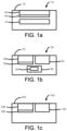
- FIG. 1 a - c each are a simplified schematic of a build module for generating a three-dimensional object according to some examples
- FIG. 2 a is a simplified perspective view on of an additive manufacturing system according to some examples
- FIG. 2 b is a simplified perspective view of a removable build module for an additive manufacturing system according to some examples
- FIG. 2 c is a simplified perspective view of a removable build module for an additive manufacturing system according to some examples
- FIG. 2 d is a simplified perspective view of a build assembly of a build module according to some examples
- FIG. 2 e is a simplified side view of a build assembly of a build module according to some examples
- FIG. 2 f is a simplified perspective view on of additive manufacturing system having received removable build modules according to some examples
- FIG. 2 g is a simplified perspective view on of additive manufacturing system having received a removable build module according to some examples
- FIG. 2 h is a simplified perspective view of a removable build module for an additive manufacturing system according to some examples
- FIG. 3 is a simplified side view of a build assembly of a build module according to some examples
- FIG. 4 is a flow diagram illustrating a method of three-dimensional object according to some examples.
- FIGS. 5 a - d show a series of cross-sectional side views of layers of build material according to some examples.
- a three-dimensional object may be generated through the solidification of portions of one or more successive layers of build material.
- the build material can be powder-based and the properties of generated objects are dependent on the type of build material and the type of solidification mechanism used.
- solidification may be achieved using a liquid binder agent to chemically solidify build material.
- solidification may be achieved by temporary application of energy to the build material. This may, for example, involve use of a coalescing agent, which is a material that, when a suitable amount of energy is applied to a combination of build material and coalescing agent, may cause the build material to coalesce and solidify.
- a coalescing agent which is a material that, when a suitable amount of energy is applied to a combination of build material and coalescing agent, may cause the build material to coalesce and solidify.
- other methods of solidification may be used.
- additive manufacturing systems may, for example, have designs that do not provide sufficient flexibility and speed. For example, printing continuity may be difficult to maintain when build material needs re-filling or the system needs cleaning. Additionally, there may be time delays between printing jobs. Moreover, in some examples these systems may have designs requiring a high degree of user interaction such as handling build material and cleaning.
- the present disclosure provides build modules that are removably insertable into an additive manufacturing system.
- the modular design may, for example, provide versatility by allowing different types of build modules to be inserted such as different sizes and/or multiple build modules at the same time.
- the modular design may also enable high productivity by allowing faster use and fewer interruptions in continued use of the system, for example allowing successive print jobs to be completed with little or no time delays in between.
- the build modules may be provided with housings in which a build chamber, build material chamber, and/or motor may be provided for movement of the chambers. This design may allow faster cleaning of a build module when it is removed.
- the build modules may also be easily insertable and removable to and from an additive manufacturing system.
- FIG. 1 a is a simplified schematic of a build module 10 according to some examples.
- the build module 10 may include a housing 12 and a build material chamber 14 in the housing 12 to hold build material.
- the build module may include a build chamber 16 in the housing 12 .
- the build material chamber 14 may be beneath the build chamber 16 .
- the build chamber 16 may include a moveable support member 18 to receive successive layers of the build material from a build material distributor.
- the build module 10 may be removably insertable into a build receiver of an additive manufacturing system to allow the additive manufacturing system to solidify a portion the successive layers to be received onto the movable support member 18 .
- FIG. 1 b is a simplified schematic of a build module 50 according to some examples.
- the build module 50 may include a housing 52 and a build material chamber 54 in the housing 52 to hold build material.
- the build module 50 may include a build chamber 56 in the housing 52 .
- the build chamber 56 comprising a moveable support member 58 to receive successive layers of the build material from a build material distributor.
- the build module 50 may include a computer-readable medium 60 in the housing 52 .
- the computer-readable medium 60 may include build module data 62 representing a feature of the build module 50 .
- the build module 50 may be removably insertable into a build volume of an additive manufacturing system to allow the additive manufacturing system to solidify a portion of the successive layers to be received onto the movable support member 58 .
- FIG. 1 c is a simplified schematic of a build module 100 according to some examples.
- the build module 100 may include a housing 102 and a build material chamber 104 in the housing 102 to hold build material.
- the build module 100 may each include a build chamber 106 in the housing 102 .
- Each build chamber 106 may include a moveable support member 108 to receive successive layers of the build material from a build material distributor.
- the build module 100 may be removably insertable into a build volume of an additive manufacturing system at a same time as another such build module to allow the additive manufacturing system to solidify a portion of the successive layers to be received onto the movable support member 108 .
- FIG. 2 a is a simplified perspective view of an additive manufacturing system 200 according to some examples.
- the additive manufacturing system 200 may include a housing 202 .
- the housing 202 may house various components, such as an agent distributor and other components, as will be discussed in more detail.
- the housing 202 may include side housing portions 204 , a central housing portion 206 , and a back housing portion 208 . Surfaces of these housing elements may define build receiver comprising a receiving volume.
- FIG. 2 a shows the receiving volume 212 having a cuboid shape, but in other examples the receiving volume 212 may have other shapes depending on the configuration and shapes of the side housing portions 204 , a central housing portion 206 , and a back housing portion 208 .
- the central housing portion 206 and the receiving volume 212 may extend to a sufficient length along the y-axis direction such that the system 200 may be considered a wide-format system.
- the central housing portion 206 and the receiving volume 212 may have shorter or longer lengths along the y-axis direction.
- the system 200 may be a smaller desktop system.
- the additive manufacturing system 200 may include a system controller 256 , which may include a processor 258 for executing instructions such as those described in the methods herein.
- the processor 258 may, for example, be a microprocessor, a microcontroller, a programmable gate array, an application specific integrated circuit (ASIC), a computer processor, or the like.
- the processor 258 may, for example, include multiple cores on a chip, multiple cores across multiple chips, multiple cores across multiple devices, or combinations thereof.
- the processor 258 may include at least one integrated circuit (IC), other control logic, other electronic circuits, or combinations thereof.
- IC integrated circuit
- the controller 256 may support direct user interaction.
- system 200 may include user input devices coupled to the processor 258 , such as one or more of a keyboard, touchpad, buttons, keypad, dials, mouse, track-ball, card reader, or other input devices.
- the system 200 may include output devices coupled to the processor 258 , such as one or more of a liquid crystal display (LCD), printer, video monitor, touch screen display, a light-emitting diode (LED), or other output devices.
- the output devices may be responsive to instructions to display textual information or graphical data.
- the processor 258 may be in communication with a computer-readable storage medium 260 via a communication bus.
- the computer-readable storage medium 260 may include a single medium or multiple media.
- the computer readable storage medium 260 may include one or both of a memory of the ASIC, and a separate memory in the controller 256 .
- the computer readable storage medium 260 may be any electronic, magnetic, optical, or other physical storage device.
- the computer-readable storage medium 260 may be, for example, random access memory (RAM), static memory, read only memory, an electrically erasable programmable read-only memory (EEPROM), a hard drive, an optical drive, a storage drive, a CD, a DVD, and the like.
- the computer-readable storage medium 260 may be non-transitory.
- the computer-readable storage medium 260 may store, encode, or carry computer executable instructions 262 that, when executed by the processor 258 , may cause the processor 258 to perform any one or more of the methods or operations disclosed herein according to various examples
- FIG. 2 b - c are simplified perspective views of a removable build module 214 for an additive manufacturing system 200 according to some examples.
- the build module 214 may include a housing 216 . Wheels 218 may be attached to a bottom surface of the housing 216 such that the build module 214 may be rolled as a trolley. Alternatively, fixed legs may be provided rather than wheels. However, in some examples no wheels 218 or legs may be attached.
- a cover 222 may be removably coupled to the housing 216 to form part of the top surface of the build module 214 . When the cover 222 is removed, as shown in FIG. 2 b , a build assembly 224 , which may be contained in the housing 216 , may be exposed.
- FIG. 2 c shows the cover attached. The housing 216 and cover 222 may prevent build material from unintentionally escaping from the build module 214 .
- the build assembly 224 may be removable as a drawer from the housing 216 by a user using a handle 220 attached to a side surface of the build assembly 224 . Additional handles may be provided on the surface of the build assembly 224 .
- an automatic and/or electronic mechanism may be used to open the drawer automatically when, for example, a user provides input such as pressing a button on the housing 216 , build assembly 224 , or on the system 200 .
- FIG. 2 d - e respectively are a simplified perspective view and a simplified side view of a build assembly 224 of a build module 214 according to some examples. As shown, the build assembly 224 has been fully removed from the housing 216 .
- the build assembly 224 may include a build material chamber 226 and a build chamber 228 .
- a support member 230 may be provided in the build material chamber 226 .
- a piston 232 may be attached to a bottom surface of the support member 230 .
- a motor 234 may drive the piston 232 to cause the support member 230 to be movable along the z-axis.
- a support member 236 may be provided in the build chamber 228 .
- a piston 238 may be attached to a bottom surface of the support member 236 .
- a motor 240 may drive the piston 238 to cause the support member 236 to be movable along the z-axis.
- the support members 230 and 236 may have dimensions in the range of from about 10 cm by 10 cm up to 100 cm by 100 cm. In other examples the support members 230 and 236 may have larger or smaller dimensions.
- FIG. 2 e shows build material 246 in storage on the top surface of the support member 230 in the build material chamber 226 .
- FIG. 2 e also shows a previously deposited layer 248 of build material on the top surface of the support member 236 in the build chamber 228 .
- the previously deposited layer 248 of build material includes a portion 250 that has been processed and solidified into part of a three-dimensional object using the additive manufacturing system 200 .
- the build material may be a powder-based build material.
- powder-based materials is intended to encompass both dry and wet powder-based materials, particulate materials, and granular materials.
- the build material may include a mixture of air and solid polymer particles, for example at a ratio of about 40% air and about 60% solid polymer particles.
- One suitable material may be Nylon 12, which is available, for example, from Sigma-Aldrich Co. LLC.
- Another suitable Nylon 12 material may be PA 2200 which is available from Electro Optical Systems EOS GmbH.
- suitable build materials may include, for example, powdered metal materials, powdered composite materials, powder ceramic materials, powdered glass materials, powdered resin material, powdered polymer materials, and the like.
- the examples described herein are not limited to powder-based materials or to any of the materials listed above.
- the build material may be a paste or a gel.
- a suitable build material may be a powdered semi-crystalline thermoplastic material.
- the build assembly 224 may include a build material distributor 242 , such as, for example, a wiper blade or a roller.
- the build material distributor 242 may be driven by a motor 244 to provide, e.g. deliver and/or deposit, successive layers of build material from the support member 230 in the build material chamber 226 to the support member 236 in the build material chamber 228 .
- the build material distributor 242 may instead be a component of the system 200 and attached to or in the housing 202 .
- a fastener member 252 may be attached to the housing 22 at the bottom surface of the central housing portion 206 .
- fastener members may be attached the side housing portions 204 and/or the back housing portion 208 .
- the fastener member 252 is shown longitudinally extending along the length of the central housing portion 206 , but in other examples the fastener member 252 may have other configurations.
- multiple separate fastener members 252 may be provided at different points along the length of the bottom surface of the central housing portion 206 .
- a fastener member 254 may be attached to the top surface of the housing 216 .
- fastener members may be attached to any other surfaces of the housing 216 , including any of the four side surfaces.
- the fastener member 254 is shown longitudinally extending along the length of the housing 216 , but in other examples the fastener member 254 may have other configurations. In some examples, multiple separate fastener members 254 may be provided at different points along the length of the top surface of the housing 216 .
- the fastening members 252 and 254 may be coupled such that the additive manufacturing system 200 can removably couple to and removably receive the build module 214 in the receiving volume 212 .
- the build module 214 may be received laterally or generally laterally, e.g. horizontally or generally horizontally, into the receiving volume 212 .
- the fasteners 252 and 254 may be magnetic fasteners, mechanical fasteners, and/or other types of fasteners.
- the fasteners 252 and 254 are magnetic fasteners, they may each be magnetic, meaning that they each may be made of a suitable material such that it experiences a force in the presence of a magnetic field, and/or itself generates a magnetic field. Thus, when the fasteners 252 and 254 are in sufficient proximity, they may be attracted to lock the build module 214 in the additive manufacturing system 200 .
- the fasteners 252 and 254 may include permanent magnets such as ferromagnets, or anti-ferromagnets, ferrimagnets, paramagnets, diamagnets, or electromagnets.
- one of the fasteners 252 and 254 may be a latch member and the other a receiving member.
- the latch may be inserted into or attached to the receiving member to lock the build module 214 in the additive manufacturing system 200 .
- the cover 222 is intended to be removed such that components in the system such as agent distributors, energy sources, heaters, and sensors may be able to interact with the build chamber 228 and any build material therein, as will be discussed.
- FIGS. 2 f - g are simplified perspective views of additive manufacturing system having received removable build modules according to some examples.
- build modules may have any length along the x-axis direction or y-axis direction.
- build modules 214 a - d of various sizes may have any length along the x-axis direction.
- a single build module 214 d has a length along the y-axis direction that allows it to fill the entire y-axis length of the receiving volume 212 when inserted in the system 200 .
- FIG. 1 is simplified perspective views of additive manufacturing system having received removable build modules according to some examples.
- build modules may have any length along the x-axis direction or y-axis direction.
- build modules 214 a - d of various sizes may have any length along the x-axis direction.
- a single build module 214 d has a length along the y-axis direction that allows it to fill the entire y-axis length of the receiving volume 212 when inserted in the system
- multiple build modules 214 a - c with smaller lengths along the y-axis direction may be lined up along the y-axis direction to collectively fill the entire receiving volume 212 .
- build chambers and support members of the build modules 214 - a - c may be lined up in series.
- build modules of different lengths are shown, for example build modules 214 a - c have different length relative to each other.
- FIG. 2 h is a simplified perspective view of the removable build module 214 c for an additive manufacturing system according to some examples.
- the build module 214 c is shown removed from the system 200 in FIG. 2 f .
- the build module 214 c may have a build material chamber 226 c that is longer along the y-axis direction than the build material chamber 226 of build module 214 , and may have a build chamber 228 c that is longer along the y-direction than the build material chamber 228 .
- the build module 214 d may have chambers spanning the entire length of the build module 214 d along the y-axis direction.
- the build modules and chambers may also vary in width along the x-axis direction.
- FIG. 3 is a simplified side view of a build assembly 324 of a build module according to some examples.
- the housing 216 of FIGS. 2 b - c may also be able to removably receive the build assembly 324 .
- the cover 222 may be removable from the housing 216 to expose the build assembly 324 and its build chamber 328 .
- the build assembly 324 may be removable as a drawer from the housing 216 by a user using a handle attached to a side surface of the build assembly 324 . Additional handles may be provided on the surface of the build assembly 324 .
- an automatic and/or electronic mechanism may be used to open the drawer automatically when, for example, a user provides input such as pressing a button on the housing 216 , build assembly 324 , or system 200 .
- the build assembly 324 has been fully removed from the housing 216 .
- the build assembly 324 may include a build material chamber 326 and a build chamber 328 .
- the build material chamber 326 may be beneath the build material chamber 326 . This may, for example, allow the build chamber 328 to be wide such that wide layers of build material may be delivered thereto.
- a support member 330 may be provided in the build material chamber 326 .
- Build material 246 is shown in storage on the top surface of the support member 330 in the build material chamber 326 .
- the support member 330 may be angled to allow build material 246 to slide down by the force of gravity.
- a support member 336 may be provided in the build chamber 328 .
- a previously deposited layer 248 of build material is shown on the top surface of the support member 336 in the build chamber 328 .
- the previously deposited build material includes the portion 250 that has been processed and solidified into part of a three-dimensional object using the additive manufacturing system 200 .
- a piston 338 may be attached to a bottom surface of the support member 336 .
- a motor 340 may drive the piston 338 to cause the support member 336 to be movable along the z-axis.
- the support members 330 and 336 may have dimensions in the range of from about 10 cm by 10 cm up to 100 cm by 100 cm. In other examples the support members 330 and 336 may have larger or smaller dimensions.
- One or more build material distributors 332 , 384 , and 342 may be used to provide, e.g. deliver and/or deposit, successive layers of build material from the support member 330 in the build material chamber 326 to the support member 336 in the build material chamber 326 .
- the build material distributor 332 for example a rotatable ball, wheel, or roller, may be attached in the build material chamber 326 .
- a motor 234 may driver the build material distributor 332 to rotate to move the build material 246 as shown by the curved arrow.
- a build material distributor 384 attached to the assembly 324 for example, a conveyor, may be driven by a motor 344 to then move the build material 246 upwards in the z-axis direction, as shown by the arrow.
- the build material distributor 384 may be rotary system having blades which, when rotated, move the build material 246 upwards in the z-axis direction.
- a build material distributor 342 attached to the build assembly 324 may be driven by a motor 344 to move longitudinally in the x-axis direction to roll build material onto the support member 336 in the build material chamber 326 .
- the build material distributor 342 may instead be a component of the system 200 and attached to or in the housing 202 .
- any of the build assemblies described herein may use build material distributors providing pneumatic or hydraulic transport of build material, wherein such build material distributors may be driven by motors.
- the build module 214 may include a controller and computer-readable medium having similar features as the controller 256 and computer-readable medium 260 described earlier.
- the computer-readable medium may store data and/or instructions specifying features of the build module 214 , for example its size, the size of each of its chambers, the type of build material stored provided in its build material chamber, and the like. These data and/or instructions may be stored for access by the controller 256 when the build module 214 is inserted in the system 200 for generating a three-dimensional object.
- an input device having similar features as the input devices of the controller 256 discussed earlier, on the build module may receive input from a user regarding the type of build material stored in the build module 214 .
- a sensor on the build module 214 may automatically detect the type of build material.
- the additive manufacturing system 200 may include a coalescing agent distributor 268 to selectively deliver coalescing agent to successive layers of build material provided on one or more support members 236 in one or more build chambers 228 , which will be discussed.
- a coalescing agent is a material that, when a suitable amount of energy is applied to a combination of build material and coalescing agent, may cause the build material to coalesce and solidify.
- a suitable coalescing agent may be an ink-type formulation comprising carbon black, such as, for example, the ink formulation commercially known as CM997A available from Hewlett-Packard Company.
- such an ink may additionally comprise an infra-red light absorber.
- such an ink may additionally comprise a near infra-red light absorber.
- such an ink may additionally comprise a visible light absorber.
- inks comprising visible light enhancers are dye based colored ink and pigment based colored ink, such as inks commercially known as CM993A and CE042A available from Hewlett-Packard Company.
- the controller 256 may control the selective delivery of coalescing agent to a layer of provided build material in accordance with instructions comprising agent delivery control data 266 stored in the computer-readable medium 260 .
- the agent distributor 268 may be a printhead, such as a thermal printhead or a piezo inkjet printhead.
- the printhead may have arrays of nozzles.
- a printhead such as those commonly used in commercially available inkjet printers may be used.
- the agents may be delivered through spray nozzles rather than through printheads. Other delivery mechanisms may be used as well.
- the agent distributor 268 may be used to selectively deliver, e.g. deposit, coalescing agent when in the form of suitable fluids such as liquids.
- the agent distributor 268 may be selected to deliver drops of agent at a resolution of between 300 to 1200 dots per inch (DPI), for example 600 DPI.
- DPI dots per inch
- the agent distributor 268 may be selected to be able to deliver drops of agent at a higher or lower resolution.
- the agent distributor 268 may have an array of nozzles through which the agent distributor 268 is able to selectively eject drops of fluid.
- each drop may be in the order of about 10 pico liters (pl) per drop, although in other examples an agent distributor 268 that is able to deliver a higher or lower drop size may be used. In some examples an agent distributor 268 that is able to deliver variable size drops may be used.
- the agent distributor 268 may be an integral part of the system 200 .
- the agent distributor 268 may be user replaceable rather than fixed, in which case it may be removably receivable, e.g. insertable, into a suitable agent distributor receiver, e.g. interface module, of the system 200 .
- the agent distributor 268 has a length in the x-axis direction that enables it to span the whole width in the x-axis direction of the support member 236 or 336 of the build module 214 in a so-called page-wide array configuration. In one example this may be achieved through a suitable arrangement of multiple printheads. In other examples a single printhead having an array of nozzles having a length to enable them to span the width of the support member 236 or 336 may be used. In other examples, the agent distributor 268 may have a shorter length that does not enable them to span the whole width of the support member 236 or 336 .
- the agent distributor 268 may be mounted on a moveable carriage to enable it to move bi-directionally across the entire length of the series of one or more support members 236 or 336 along the illustrated y-axis, as shown by arrows 270 . This enables selective delivery of coalescing agent across the whole width and length of the support members 236 or 336 in a single pass.
- width used herein is used to generally denote the shortest dimension in the plane parallel to the x and y axes illustrated in FIGS. 2 a - e
- length used herein is used to generally denote the longest dimension in this plane.
- the term ‘width’ may be interchangeable with the term ‘length’.
- the agent distributor 268 may have a length that enables it to span the whole length of the support member 236 or 336 whilst the moveable carriage may move bi-directionally across the width of the support members 236 or 336 .
- the agent distributor 268 does not have a length that enables it to span the whole width of the support member 236 or 336 but is additionally movable bi-directionally across the width of the support member 236 or 336 in the illustrated x-axis.
- This configuration enables selective delivery of coalescing agent across the whole width and length of the support member 236 or 336 using multiple passes.
- Other configurations, however, such as a page-wide array configuration, may enable three-dimensional objects to be created faster.
- the coalescing agent distributor 268 may include a supply of coalescing agent or may be connectable to a separate supply of coalescing agent.
- coalescing agent distributors there may be additional coalescing agent distributors, such as the agent distributor 274 .
- the distributors of system 200 may be located on the same carriage, either adjacent to each other or separated by a short distance.
- two or more carriages each may contain one or more distributors.
- each distributor may be located in its own separate carriage. Any additional distributors may have similar features as those discussed earlier with reference to the coalescing agent distributor 268 .
- different agent distributors may deliver different coalescing agents, for example.
- the system 200 may additionally include an energy source 272 attached to the housing 202 .
- the energy source 272 may be to apply energy to build material to cause the solidification of portions of the build material according to where coalescing agent has been delivered or has penetrated.
- the energy source 272 is an infra-red (IR) radiation source, near infra-red radiation source, or halogen radiation source.
- the energy source 272 may be a single energy source that is able to uniformly apply energy to build material deposited on the support member 236 or 336 .
- the energy source 272 may comprise an array of energy sources.
- the energy source 272 is configured to apply energy in a substantially uniform manner to the whole surface of a layer of build material.
- the energy source 272 may be said to be an unfocused energy source.
- a whole layer may have energy applied thereto simultaneously, which may help increase the speed at which a three-dimensional object may be generated.
- the energy source 272 is configured to apply energy in a substantially uniform manner to a portion of the whole surface of a layer of build material.
- the energy source 272 may be configured to apply energy to a strip of the whole surface of a layer of build material.
- the energy source may be moved or scanned across the layer of build material such that a substantially equal amount of energy is ultimately applied across the whole surface of a layer of build material.
- the energy source 272 may be mounted on the moveable carriage.
- the energy source 272 may apply a variable amount of energy as it is moved across the layer of build material, for example in accordance with agent delivery control data 266 .
- the controller 210 may control the energy source only to apply energy to portions of build material on which coalescing agent has been applied.
- the energy source 272 may be a focused energy source, such as a laser beam.
- the laser beam may be controlled to scan across the whole or a portion of a layer of build material.
- the laser beam may be controlled to scan across a layer of build material in accordance with agent delivery control data.
- the laser beam may be controlled to apply energy to those portions of a layer of on which coalescing agent is delivered.
- the system 200 may additionally include a heater or pre-heater to emit heat to maintain build material deposited on the support members 236 within a predetermined temperature range.
- the heater may have an array of heating units.
- the heating units may each be any suitable heating unit, for example a heat lamp such as an infra-red lamp.
- the configuration may be optimized to provide a homogeneous heat distribution toward the area spanned by the build material.
- Each heating unit, or groups of heating units may have an adjustable current or voltage supply to variably control the local energy density applied to the build material surface.
- FIG. 4 is a flow diagram illustrating a method 400 of generating a three-dimensional object according to some examples.
- the method may be computer implemented.
- the orderings shown may be varied, such that some steps may occur simultaneously, some steps may be added, and some steps may be omitted.
- FIGS. 5 a - d show a series of cross-sectional side views of layers of build material according to some examples.
- the controller 210 may obtain agent delivery control data 266 .
- the agent delivery control data 266 may define for each slice of the three-dimensional object to be generated the portions or the locations on the build material, if any, at which coalescing agents are to be delivered.
- the agent delivery control data 266 may be derived by a suitable three-dimensional object processing system in or outside of the system 200 .
- the agent delivery control data 266 may be generated based on object design data representing a three-dimensional model of an object to be generated, and/or from object design data representing properties of the object.
- the model may define the solid portions of the object, and may be processed by the three-dimensional object processing system to generate slices of parallel planes of the model. Each slice may define a portion of a respective layer of build material that is to be solidified by the additive manufacturing system.
- the object property data may define properties of the object such as density, surface roughness, strength, and the like.
- a computer-readable medium on the build module 214 may determine and/or store build module data representing build module features such as the type of build material being used, for example based on user input or detection by a sensor. Other features of the build module, such as physical dimensions of the build module, may be pre-stored on the computer-readable medium, as discussed earlier.
- one or more build modules 214 may be received by the system 200 .
- the controller 256 of the system 200 may access the computer-readable media of build modules 214 to discover the build module data.
- a layer 276 of build material may be provided, as shown in FIG. 5 a .
- the controller 210 may control the build distributor 242 to provide the layer 276 on a previously completed layer 248 shown in FIGS. 2 e and 4 a .
- the completed layer 248 may include a solidified portion 250 .
- a completed layer 248 is shown in FIGS. 5 a - d for illustrative purposes, it is understood that the blocks 408 to 412 may initially be applied to generate the first layer 248 .
- the layer 276 may be delivered as follows.
- the support member 230 in the build material chamber 226 may be positioned by the piston 232 in the z-axis direction in such a way that a portion of the stored build material 246 extends beyond the top edge of the build assembly 224 .
- the support member 236 in the build chamber 228 may be positioned by the piston 238 in the z-axis direction in such a way that a predetermined gap is provided above the previously deposited layer 248 of build material.
- the build material distributor 242 may then move longitudinally in the x-axis direction to roll the extended portion of the stored build material 246 into the predetermined gap to create the new layer 276 in the build chamber 228 .
- the delivery may be based on the data and/or instructions regarding features of the build module stored in the computer-readable medium of the build module.
- the layer 276 may be delivered as follows.
- the support member 330 in the build material chamber 326 may be positioned by the piston 338 in the z-axis direction in such a way that a portion of the stored build material 246 extends beyond the top edge of the build assembly 324 .
- the support member 336 in the build chamber 328 may be positioned by the piston 338 in the z-axis direction in such that a predetermined gap is provided above the previously deposited layer 248 of build material.
- the build material distributors 332 , 384 , and 342 may be used to deliver the layer 276 .
- the stored build material 246 may be moved along the arrows in FIG. 3 and rolled into the predetermined gap to create the new layer 276 in the build chamber 228 .
- the delivery may be based on the data and/or instructions regarding features of the build module stored in the computer-readable medium of the build module.
- a coalescing agent 278 may be selectively delivered to one or more portions of the surface of the layer 276 of build material, as shown in FIG. 5 b .
- the selective delivery of the coalescing agent 278 may be performed in patterns on portions of the layer 276 that the agent delivery control data 266 may define to become solid to form part of the three-dimensional object being generated.
- Selective delivery means that coalescing agent may be delivered to selected portions of the surface layer of the build material in various patterns. The patterns may be defined by the agent delivery control data 266 , and based on the data and/or instructions regarding features of the build module stored in the computer-readable medium of the build module.
- FIG. 5 c shows coalescing agent 278 having penetrated substantially completely into the layer 276 of build material, but in other examples, the degree of penetration may be less than 100%.
- a predetermined level of energy may be temporarily applied to the layer 276 of build material.
- the energy applied may be infra-red or near infra-red energy, microwave energy, ultra-violet (UV) light, halogen light, ultra-sonic energy, or the like.
- the temporary application of energy may cause portions of the build material on which coalescing agent 278 has been delivered or has penetrated to heat up above the melting point of the build material and to coalesce. Upon cooling, the portions which have coalesced become solid and form part of the three-dimensional object being generated. As discussed earlier, one such portion 250 may have been generated in a previous iteration.
- the heat absorbed during the application of energy may propagate to the previously solidified portion 250 to cause part of portion 250 to heat up above its melting point. This effect helps create a portion 280 that has strong interlayer bonding between adjacent layers of solidified build material, as shown in FIG. 5 d.
- new layers of build material may be provided on top of the previously processed layer of build material.
- the previously processed layer of build material acts as a support for a subsequent layer of build material.
- the process of blocks 408 to 412 may then be repeated to generate a three-dimensional object layer by layer.
- additional build modules 214 may be received by the system 200 such as at block 406 .
- a parallel instance of the method 400 may proceed, such that the system 200 may be performing multiple print jobs at once by different three dimensional objects on different build modules 214 .
- the second instance of the method 400 may proceed with blocks 408 to 412 such that the second three-dimensional object is generated immediately after the first one is completed, with little or no time delay in between.
- the housing 216 may aid in keeping build material from escaping into undesired locations in the build module 214 .
- the build module 214 may be inserted in a cleaning device which may, for example, automatically clean the parts of the build module 214 while the motors are running such that build material may shake out from the components of the build module 214 .
- manual steps in cleaning may also be performed, for example while running the motors.
Landscapes
- Chemical & Material Sciences (AREA)
- Engineering & Computer Science (AREA)
- Materials Engineering (AREA)
- Manufacturing & Machinery (AREA)
- Physics & Mathematics (AREA)
- Mechanical Engineering (AREA)
- Optics & Photonics (AREA)
Abstract
Description
Claims (15)
Priority Applications (1)
| Application Number | Priority Date | Filing Date | Title |
|---|---|---|---|
| US17/105,378 US11618217B2 (en) | 2014-01-16 | 2020-11-25 | Generating three-dimensional objects |
Applications Claiming Priority (9)
| Application Number | Priority Date | Filing Date | Title |
|---|---|---|---|
| EPPCT/EP2014/050841 | 2014-01-16 | ||
| PCT/EP2014/050841 WO2015106816A1 (en) | 2014-01-16 | 2014-01-16 | Generating a three-dimensional object |
| WOPCT/EP2014/050841 | 2014-01-16 | ||
| PCT/US2014/014025 WO2015108545A1 (en) | 2014-01-16 | 2014-01-31 | Generating three-dimensional objects |
| USPCT/US2014/014025 | 2014-01-31 | ||
| WOPCT/US2014/014025 | 2014-01-31 | ||
| PCT/US2014/032333 WO2015108551A1 (en) | 2014-01-16 | 2014-03-31 | Generating three-dimensional objects |
| US201615112141A | 2016-07-15 | 2016-07-15 | |
| US17/105,378 US11618217B2 (en) | 2014-01-16 | 2020-11-25 | Generating three-dimensional objects |
Related Parent Applications (2)
| Application Number | Title | Priority Date | Filing Date |
|---|---|---|---|
| PCT/US2014/032333 Continuation WO2015108551A1 (en) | 2014-01-16 | 2014-03-31 | Generating three-dimensional objects |
| US15/112,141 Continuation US10889059B2 (en) | 2014-01-16 | 2014-03-31 | Generating three-dimensional objects |
Publications (2)
| Publication Number | Publication Date |
|---|---|
| US20210078250A1 US20210078250A1 (en) | 2021-03-18 |
| US11618217B2 true US11618217B2 (en) | 2023-04-04 |
Family
ID=56743994
Family Applications (2)
| Application Number | Title | Priority Date | Filing Date |
|---|---|---|---|
| US15/112,141 Active 2035-08-31 US10889059B2 (en) | 2014-01-16 | 2014-03-31 | Generating three-dimensional objects |
| US17/105,378 Active 2034-04-30 US11618217B2 (en) | 2014-01-16 | 2020-11-25 | Generating three-dimensional objects |
Family Applications Before (1)
| Application Number | Title | Priority Date | Filing Date |
|---|---|---|---|
| US15/112,141 Active 2035-08-31 US10889059B2 (en) | 2014-01-16 | 2014-03-31 | Generating three-dimensional objects |
Country Status (3)
| Country | Link |
|---|---|
| US (2) | US10889059B2 (en) |
| JP (1) | JP6570542B2 (en) |
| CN (1) | CN105916661B (en) |
Families Citing this family (25)
| Publication number | Priority date | Publication date | Assignee | Title |
|---|---|---|---|---|
| EP3094469B1 (en) | 2014-01-16 | 2019-11-13 | Hewlett-Packard Development Company, L.P. | Generating a three-dimensional object |
| RU2650155C2 (en) | 2014-01-16 | 2018-04-09 | Хьюлетт-Паккард Дивелопмент Компани, Л.П. | Formation of three-dimensional objects |
| US9868257B1 (en) * | 2014-08-13 | 2018-01-16 | Amazon Technologies, Inc. | Object fabrication system |
| US10549487B1 (en) | 2015-08-27 | 2020-02-04 | Amazon Technologies, Inc. | Safety data sheets (SDS) signing for feedstock materials |
| WO2017196347A1 (en) * | 2016-05-12 | 2017-11-16 | Hewlett-Packard Development Company, L.P. | 3d build platform refill opening and cap |
| CN109311233A (en) * | 2016-05-12 | 2019-02-05 | 惠普发展公司,有限责任合伙企业 | Additive Manufacturing Transporter |
| DE102016121769A1 (en) | 2016-11-14 | 2018-05-17 | Cl Schutzrechtsverwaltungs Gmbh | Plant for the additive production of three-dimensional objects |
| US10759111B2 (en) | 2017-04-14 | 2020-09-01 | Desktop Metal, Inc. | Smart cart for three dimensional binder jet printers |
| EP3431260B1 (en) * | 2017-07-21 | 2021-06-02 | CL Schutzrechtsverwaltungs GmbH | Apparatus for additively manufacturing of three-dimensional objects |
| US20190111621A1 (en) * | 2017-10-18 | 2019-04-18 | General Electric Company | Additive manufacturing apparatus |
| EP3533588B1 (en) | 2018-02-28 | 2023-07-12 | Sintratec AG | Additive manufacturing device comprising a replaceable raw material processing unit |
| PL3566869T3 (en) | 2018-05-08 | 2022-02-07 | 9328-8082 Québec Inc. | MODULAR ADDIVE MANUFACTURING SYSTEM AND RELATED WAYS TO CONTINUOUS PRODUCTION OF PARTS |
| FR3082449B1 (en) * | 2018-06-15 | 2020-09-04 | Safran Landing Systems | PROCESS FOR MAKING A PART WITH CAVITY BY ADDITIVE MANUFACTURING |
| DE102018219302A1 (en) * | 2018-11-12 | 2020-05-14 | Eos Gmbh Electro Optical Systems | Selective sintering of polymer-based building materials |
| EP3840938B1 (en) | 2019-03-15 | 2025-12-03 | Peridot Print LLC | Coloured objects in additive manufacturing |
| CN111515339B (en) * | 2020-01-16 | 2021-08-17 | 共享智能铸造产业创新中心有限公司 | 3D printing equipment |
| TWM596697U (en) * | 2020-03-25 | 2020-06-11 | 元力智庫有限公司 | 3D printer and its dual nozzle guiding module |
| WO2021194511A1 (en) * | 2020-03-27 | 2021-09-30 | Hewlett-Packard Development Company, L.P. | Additive manufacturing |
| CN113953534B (en) * | 2020-07-16 | 2023-08-04 | 中国航发商用航空发动机有限责任公司 | Support structure, forming method and device thereof, and storage medium |
| CN116348274A (en) | 2020-10-20 | 2023-06-27 | 通用电气公司 | Print components and how to use them |
| JP7525738B2 (en) | 2020-10-20 | 2024-07-30 | ゼネラル・エレクトリック・カンパニイ | Method for forming an object and additive manufacturing system |
| EP4232267A1 (en) | 2020-10-21 | 2023-08-30 | General Electric Company | Material supply system and method for using the same |
| WO2022093942A1 (en) | 2020-10-29 | 2022-05-05 | General Electric Company | Additive manufacturing apparatuses with removable build boxes and build box management systems |
| EP4237228B1 (en) | 2020-10-29 | 2026-03-25 | General Electric Company | Additive manufacturing apparatuses and methods for using the same |
| WO2022093691A1 (en) | 2020-10-29 | 2022-05-05 | General Electric Company | Print head assembly and methods for using the same |
Citations (253)
| Publication number | Priority date | Publication date | Assignee | Title |
|---|---|---|---|---|
| US4120630A (en) | 1976-03-12 | 1978-10-17 | Phillips Petroleum Company | Automatic control of extrusion rate |
| US4430012A (en) | 1981-04-06 | 1984-02-07 | Zenith Radio Corporation | Paper guide for line printer |
| US4579461A (en) | 1983-02-14 | 1986-04-01 | United States Steel Corporation | Dual sensor radiation pyrometer |
| US4835737A (en) | 1986-07-21 | 1989-05-30 | American Telephone And Telegraph Company, At&T Bell Laboratories | Method and apparatus for controlled removal and insertion of circuit modules |
| EP0338751A2 (en) | 1988-04-18 | 1989-10-25 | 3D Systems, Inc. | Stereolithographic supports |
| US4956538A (en) | 1988-09-09 | 1990-09-11 | Texas Instruments, Incorporated | Method and apparatus for real-time wafer temperature measurement using infrared pyrometry in advanced lamp-heated rapid thermal processors |
| JPH0493228A (en) | 1990-08-08 | 1992-03-26 | Fujitsu Ltd | Method for forming three-dimensional matter |
| US5111236A (en) | 1990-03-27 | 1992-05-05 | Lo Allen K W | Multiple-print 3-D printer and process |
| DE4112695A1 (en) | 1990-12-21 | 1992-07-02 | Eos Electro Optical Syst | METHOD AND DEVICE FOR PRODUCING A THREE-DIMENSIONAL OBJECT |
| CN1065239A (en) | 1991-03-28 | 1992-10-14 | 塔克特公司 | Inlaid sheet materials with selectively applied decorative adhesive matrix |
| US5156461A (en) | 1991-05-17 | 1992-10-20 | Texas Instruments Incorporated | Multi-point pyrometry with real-time surface emissivity compensation |
| US5182056A (en) | 1988-04-18 | 1993-01-26 | 3D Systems, Inc. | Stereolithography method and apparatus employing various penetration depths |
| US5204055A (en) | 1989-12-08 | 1993-04-20 | Massachusetts Institute Of Technology | Three-dimensional printing techniques |
| US5252264A (en) | 1991-11-08 | 1993-10-12 | Dtm Corporation | Apparatus and method for producing parts with multi-directional powder delivery |
| US5427733A (en) | 1993-10-20 | 1995-06-27 | United Technologies Corporation | Method for performing temperature-controlled laser sintering |
| US5460451A (en) | 1992-12-29 | 1995-10-24 | U.S. Philips Corporation | Pyrometer including an emissivity meter |
| WO1995034468A1 (en) | 1994-06-14 | 1995-12-21 | Soligen, Inc. | Powder handling apparatus for additive fabrication equipment |
| WO1996006881A2 (en) | 1994-08-30 | 1996-03-07 | Dtm Corporation | Sinterable semi-crystalline powder and article formed therewith |
| US5508489A (en) | 1993-10-20 | 1996-04-16 | United Technologies Corporation | Apparatus for multiple beam laser sintering |
| US5690430A (en) | 1996-03-15 | 1997-11-25 | Bethlehem Steel Corporation | Apparatus and method for measuring temperature and/or emissivity of steel strip during a coating process |
| US5696690A (en) | 1994-12-13 | 1997-12-09 | Check Technology Corporation | Sheet stacking apparatus |
| US5764521A (en) | 1995-11-13 | 1998-06-09 | Stratasys Inc. | Method and apparatus for solid prototyping |
| US5784956A (en) | 1996-05-30 | 1998-07-28 | Walz; Heinz | Apparatus for printing materials particularly textile materials ceramics paper or the like |
| CN1204277A (en) | 1995-09-27 | 1999-01-06 | 3D系统公司 | Method and apparatus for data manipulation and system control in a local deposition modeling system |
| US5866058A (en) | 1997-05-29 | 1999-02-02 | Stratasys Inc. | Method for rapid prototyping of solid models |
| US6000773A (en) | 1994-08-09 | 1999-12-14 | Encad, Inc. | Ink jet printer having ink use information stored in a memory mounted on a replaceable printer ink cartridge |
| US6162378A (en) | 1999-02-25 | 2000-12-19 | 3D Systems, Inc. | Method and apparatus for variably controlling the temperature in a selective deposition modeling environment |
| US6169605B1 (en) | 1991-01-31 | 2001-01-02 | Texas Instruments Incorporated | Method and apparatus for the computer-controlled manufacture of three-dimensional objects from computer data |
| WO2001038061A1 (en) | 1999-10-26 | 2001-05-31 | University Of Southern California | Process of making a three-dimensional object |
| US6280785B1 (en) | 2000-03-28 | 2001-08-28 | Nanotek Instruments, Inc. | Rapid prototyping and fabrication method for 3-D food objects |
| US6316948B1 (en) | 1998-07-01 | 2001-11-13 | Setra Systems, Inc. | Charge balance network with floating ground capacitive sensing |
| JP2001334581A (en) | 2000-05-24 | 2001-12-04 | Minolta Co Ltd | 3D modeling equipment |
| US20020020945A1 (en) | 2000-08-18 | 2002-02-21 | Uichung Cho | Forming three dimensional objects through bulk heating of layers with differential material properties |
| US6366825B1 (en) | 1990-10-30 | 2002-04-02 | 3D Systems, Inc. | Simultaneous multiple layer curing in stereolithography |
| US6363606B1 (en) | 1998-10-16 | 2002-04-02 | Agere Systems Guardian Corp. | Process for forming integrated structures using three dimensional printing techniques |
| US6376148B1 (en) | 2001-01-17 | 2002-04-23 | Nanotek Instruments, Inc. | Layer manufacturing using electrostatic imaging and lamination |
| US20020079601A1 (en) | 1996-12-20 | 2002-06-27 | Z Corporation | Method and apparatus for prototyping a three-dimensional object |
| US20020086247A1 (en) | 2000-10-09 | 2002-07-04 | Coe Dorsey D. | Method and system for colorizing a stereolithographically generated model |
| US20020090410A1 (en) | 2001-01-11 | 2002-07-11 | Shigeaki Tochimoto | Powder material removing apparatus and three dimensional modeling system |
| US20020105114A1 (en) | 2001-02-07 | 2002-08-08 | Minolta Co., Ltd. | Three-dimensional molding apparatus and three-dimensional molding method |
| US6438639B1 (en) | 1996-08-27 | 2002-08-20 | International Business Machines Corporation | Computer system bus network providing concurrent communication and connection transition of peripheral devices |
| JP2002292748A (en) | 2001-03-29 | 2002-10-09 | Minolta Co Ltd | Colored three-dimensional printing system and method, data processing apparatus and method for colored three-dimensional printing, data processing program for colored three-dimensional printing, and recording medium storing the data processing program |
| US20020145213A1 (en) | 2001-04-10 | 2002-10-10 | Junhai Liu | Layer manufacturing of a multi-material or multi-color 3-D object using electrostatic imaging and lamination |
| US20030044593A1 (en) | 2001-01-02 | 2003-03-06 | Vaidyanathan K. Ranji | Continuous fiber reinforced composites and methods, apparatuses, and compositions for making the same |
| US20030074096A1 (en) | 2001-10-15 | 2003-04-17 | Suman Das | Solid freeform fabrication of structurally engineered multifunctional devices |
| CN1426335A (en) | 2000-04-27 | 2003-06-25 | 阿卡姆股份公司 | Device and arrangement for producing three dimensional object |
| US6600129B2 (en) | 2000-02-19 | 2003-07-29 | Daimlerchrysler Ag | Device and process for sintering a powder with a laser beam |
| US20030151167A1 (en) | 2002-01-03 | 2003-08-14 | Kritchman Eliahu M. | Device, system and method for accurate printing of three dimensional objects |
| JP2003231182A (en) | 2002-02-07 | 2003-08-19 | Minolta Co Ltd | 3D modeling equipment and powder removal equipment |
| US6658314B1 (en) | 1999-10-06 | 2003-12-02 | Objet Geometries Ltd. | System and method for three dimensional model printing |
| US20030222066A1 (en) | 2002-05-29 | 2003-12-04 | Low Steven C. | Thermocouple control system for selective laser sintering part bed temperature control |
| US6663712B2 (en) | 1997-02-21 | 2003-12-16 | Speedline Technologies, Inc. | Dual track stenciling system with solder gathering head |
| US6666540B2 (en) | 2001-06-19 | 2003-12-23 | Seiko Epson Corporation | Detection of a print recording material reservoir |
| WO2004011159A1 (en) | 2002-07-31 | 2004-02-05 | Metso Minerals (Tampere) Oy | Method for controlling a screening machine and a screening machine |
| US20040035542A1 (en) | 2000-09-26 | 2004-02-26 | Ingo Ederer | Device for manufacturing models layer by layer |
| DE10311446A1 (en) | 2002-09-21 | 2004-04-01 | Degussa Ag | Polymer powder for SIV processes |
| JP2004114685A (en) | 2002-09-21 | 2004-04-15 | Degussa Ag | Method for producing three-dimensional object, molded object obtainable by the method, and powdery material and bond suppressing material for the method |
| US20040084814A1 (en) | 2002-10-31 | 2004-05-06 | Boyd Melissa D. | Powder removal system for three-dimensional object fabricator |
| US20040133298A1 (en) | 2002-10-31 | 2004-07-08 | Ehsan Toyserkani | System and method for closed-loop control of laser cladding by powder injection |
| EP1452298A1 (en) | 2003-02-28 | 2004-09-01 | Hewlett-Packard Development Company, L.P. | Methods and systems for producing an object through solid freeform fabrication using immiscible fluids |
| US20040183796A1 (en) | 2002-12-11 | 2004-09-23 | Velde Koen Vande | Method and apparatus for creating 3D-prints and a 3-D printing system |
| US20040187714A1 (en) | 2000-03-13 | 2004-09-30 | Eduardo Napadensky | Compositons and methods for use in three dimensional model printing |
| US6799959B1 (en) | 1999-09-14 | 2004-10-05 | Minolta Co., Ltd. | Apparatus for forming a three-dimensional product |
| US6802581B2 (en) | 2002-07-30 | 2004-10-12 | Hewlett-Packard Development Company, L.P. | Method, program product and system for ink management control |
| EP1466718A2 (en) | 2003-04-09 | 2004-10-13 | 3D Systems, Inc. | Sintering using thermal image feedback |
| US20040251581A1 (en) | 2003-06-16 | 2004-12-16 | Jang Bor Z. | Micro- and nano-fabrication using focused plasma assisted vapor deposition |
| US6838035B1 (en) | 1999-10-08 | 2005-01-04 | Voxeljet Technology Gmbh | Rapid-prototyping method and apparatus |
| JP2005007572A (en) | 2003-04-22 | 2005-01-13 | Fuji Photo Film Co Ltd | Manufacturing method of three-dimensional structure |
| WO2005007390A1 (en) | 2003-07-14 | 2005-01-27 | Therics, Inc. | Three-dimensional printing apparatus and methods of manufacture including sterilization or disinfection, for example, using ultraviolet light |
| US20050025905A1 (en) | 2003-07-30 | 2005-02-03 | Hewlett-Packard Company | Stereolithographic method and apparatus for forming three-dimensional structure |
| JP2005503939A (en) | 2001-09-27 | 2005-02-10 | ゼット コーポレーション | 3D printer |
| WO2005011959A1 (en) | 2003-07-25 | 2005-02-10 | Loughborough University Enterprises Limited | Method and apparatus for combining particulate material |
| US20050049739A1 (en) | 2003-08-25 | 2005-03-03 | Laura Kramer | Method and a system for solid freeform fabrication using non-reactive powder |
| US20050079086A1 (en) | 2003-10-14 | 2005-04-14 | Isaac Farr | System and method for fabricating a three-dimensional metal object using solid free-form fabrication |
| US20050079132A1 (en) | 2003-04-08 | 2005-04-14 | Xingwu Wang | Medical device with low magnetic susceptibility |
| US20050104241A1 (en) | 2000-01-18 | 2005-05-19 | Objet Geometried Ltd. | Apparatus and method for three dimensional model printing |
| JP2005132110A (en) | 2003-10-28 | 2005-05-26 | Hewlett-Packard Development Co Lp | Solid freeform fabrication system and its forming method |
| US6930278B1 (en) | 2004-08-13 | 2005-08-16 | 3D Systems, Inc. | Continuous calibration of a non-contact thermal sensor for laser sintering |
| TWI239888B (en) | 2002-09-30 | 2005-09-21 | Matsushita Electric Works Ltd | Method of making three-dimensional object |
| US20050208168A1 (en) | 2004-03-18 | 2005-09-22 | Hickerson Kevin P | Apparatus for three dimensional printing using image layers |
| US6948901B2 (en) | 2002-11-12 | 2005-09-27 | Metso Paper Ag | Paper roll storage and handling installation and method for storing and handling paper rolls |
| WO2005090055A1 (en) | 2004-03-16 | 2005-09-29 | Degussa Ag | Method and device for producing three-dimensional objects using laser technology and for applying an absorber using an ink jet method |
| US20050225007A1 (en) | 2004-04-08 | 2005-10-13 | Wei-Hsian Lai | Method and apparatus for rapid prototyping using computer-printer aided to object realization |
| JP2005335199A (en) | 2004-05-26 | 2005-12-08 | Matsushita Electric Works Ltd | Method for recycling powder material in the manufacture of three-dimensional shape and powder material recycling device |
| US20050280185A1 (en) | 2004-04-02 | 2005-12-22 | Z Corporation | Methods and apparatus for 3D printing |
| US20060054039A1 (en) | 2002-12-03 | 2006-03-16 | Eliahu Kritchman | Process of and apparratus for three-dimensional printing |
| US20060061618A1 (en) | 2004-09-21 | 2006-03-23 | Z Corporation | Apparatus and methods for servicing 3D printers |
| US20060060100A1 (en) | 2003-04-15 | 2006-03-23 | Inov-Media, A Corporation Of France | Method and system for printing a plurality of base materials |
| US20060085088A1 (en) | 2003-06-03 | 2006-04-20 | Shintaro Nakayama | Process animation automatic generation method and system |
| US7037382B2 (en) | 1996-12-20 | 2006-05-02 | Z Corporation | Three-dimensional printer |
| US20060091199A1 (en) | 2004-10-29 | 2006-05-04 | Loughran Stephen A | Retrieving information on material used in solid freeform fabrication |
| US20060091842A1 (en) | 2004-10-29 | 2006-05-04 | Denso Wave Incorporated | Factory line system for robot-arm work stations |
| US20060111807A1 (en) | 2002-09-12 | 2006-05-25 | Hanan Gothait | Device, system and method for calibration in three-dimensional model printing |
| CN1789928A (en) | 2005-12-07 | 2006-06-21 | 西安交通大学 | Resin level detection method for ultraviolet curing quick forming process |
| JP2006183146A (en) | 2004-12-07 | 2006-07-13 | Three D Syst Inc | Controlled cooling method and apparatus for laser sintering part-cake |
| GB2422344A (en) | 2005-01-24 | 2006-07-26 | Univ Montfort | Rapid prototyping using infrared sintering |
| US20060192315A1 (en) | 2005-02-25 | 2006-08-31 | Isaac Farr | Core-shell solid freeform fabrication |
| EP1704989A2 (en) | 2005-03-23 | 2006-09-27 | 3D Systems, Inc. | Apparatus and method for aligning a removable build chamber within a process chamber |
| EP1707341A1 (en) | 2005-03-31 | 2006-10-04 | 3D Systems, Inc. | Thermal management system for a removable build chamber for use with a laser sintering system |
| US20060249884A1 (en) | 2005-05-03 | 2006-11-09 | 3D Systems, Inc. | Bubble-free cross-sections for use in solid imaging |
| US20060290032A1 (en) | 2003-03-10 | 2006-12-28 | Shojiro Sano | Process for producing three-dimensional shaped article |
| US20070023977A1 (en) | 2003-09-15 | 2007-02-01 | Stefan Braun | Substrate sheet for a 3d-shaping method |
| JP2007021747A (en) | 2005-07-12 | 2007-02-01 | Imageom:Kk | Powder sintering and shaping apparatus and powder sintering and shaping method |
| EP1764208A2 (en) | 2005-09-19 | 2007-03-21 | Hewlett-Packard Development Company, L.P. | System and methods of solid freeform fabrication with interchangeable powder bins |
| CN1939706A (en) | 2005-09-30 | 2007-04-04 | 3D系统公司 | Rapid prototyping and manufacturing system and method |
| WO2007039450A1 (en) | 2005-09-20 | 2007-04-12 | Pts Software Bv | An apparatus for building a three-dimensional article and a method for building a three-dimensional article |
| US20070109340A1 (en) | 2005-04-21 | 2007-05-17 | Nicodem Harry E | Method and Apparatus for a Printer Cartridge Tester |
| CN1976800A (en) | 2005-04-06 | 2007-06-06 | Eos有限公司电镀光纤系统 | Device and method for the production of a three-dimensional object |
| CN1976799A (en) | 2004-04-27 | 2007-06-06 | 德古萨公司 | Method and device for production of three-dimensional objects by means of electromagnetic radiation and application of an absorber by means of an ink-jet method |
| US20070158411A1 (en) | 2005-11-28 | 2007-07-12 | Eye Q Development, Inc. | Method and system for storing, retrieving and updating information from an information card |
| JP2007219628A (en) | 2006-02-14 | 2007-08-30 | Three M Innovative Properties Co | Sample sheet preparation system and method |
| US20070228590A1 (en) | 2006-04-03 | 2007-10-04 | Stratasys, Inc. | Single-motor extrusion head having multiple extrusion lines |
| US20070241482A1 (en) | 2006-04-06 | 2007-10-18 | Z Corporation | Production of three-dimensional objects by use of electromagnetic radiation |
| CN101076550A (en) | 2004-04-27 | 2007-11-21 | 德古萨公司 | Polymer powder comprising polyamide use thereof in a moulding method and moulded body made from said polymer powder |
| WO2007147221A1 (en) | 2006-06-20 | 2007-12-27 | Katholieke Universiteit Leuven | Procedure and apparatus for in-situ monitoring and feedback control of selective laser powder processing |
| EP1872928A1 (en) | 2006-06-30 | 2008-01-02 | Voxeljet Technology GmbH | Method and device for building up three-dimensional parts |
| WO2008055533A1 (en) | 2006-11-10 | 2008-05-15 | Envisiontec Gmbh | Continuous, generative method and apparatus for the production of a three-dimensional object |
| US20080131546A1 (en) | 2006-11-22 | 2008-06-05 | Eos Gmbh Electro Optical Systems | Device for a layerwise manufacturing of a three-dimensional object |
| US7407256B2 (en) | 2006-02-02 | 2008-08-05 | Samsung Electronics Co., Ltd. | Method and apparatus to compensate for defective nozzle of inkjet image forming device |
| US7433627B2 (en) | 2005-06-28 | 2008-10-07 | Xerox Corporation | Addressable irradiation of images |
| WO2008151063A2 (en) | 2007-05-31 | 2008-12-11 | Milton Meisner | High definition versatile stereolithic method and material |
| US20090020920A1 (en) | 2007-07-17 | 2009-01-22 | Seiko Epson Corporation | Three-dimensional object forming apparatus and method for forming three dimensional object |
| WO2009013751A2 (en) | 2007-07-25 | 2009-01-29 | Objet Geometries Ltd. | Solid freeform fabrication using a plurality of modeling materials |
| JP2009040032A (en) | 2007-07-17 | 2009-02-26 | Seiko Epson Corp | 3D modeling apparatus and 3D modeling method |
| US7515986B2 (en) | 2007-04-20 | 2009-04-07 | The Boeing Company | Methods and systems for controlling and adjusting heat distribution over a part bed |
| US20090152771A1 (en) | 2007-11-27 | 2009-06-18 | Eos Gmbh Electro Optical Systems | Method of manufacturing three-dimensional objects by laser sintering |
| US20090229936A1 (en) | 2008-03-13 | 2009-09-17 | Targus Group International, Inc. | Portable computer case |
| US20100043698A1 (en) | 2007-02-23 | 2010-02-25 | The Ex One Company,LLC | Replaceable build box for three dimensional printer |
| US7680555B2 (en) | 2006-04-03 | 2010-03-16 | Stratasys, Inc. | Auto tip calibration in an extrusion apparatus |
| JP2010090350A (en) | 2008-10-10 | 2010-04-22 | Jsr Corp | Resin powder for molding laser sintering laminated layer |
| US20100121476A1 (en) | 2007-04-01 | 2010-05-13 | Kritchman Eliahu M | Method and system for three-dimensional fabrication |
| US20100125356A1 (en) | 2008-11-18 | 2010-05-20 | Global Filtration Systems | System and Method for Manufacturing |
| US7722151B2 (en) | 2007-01-30 | 2010-05-25 | Hewlett-Packard Development Company, L.P. | Printing apparatus |
| US20100155985A1 (en) | 2008-12-18 | 2010-06-24 | 3D Systems, Incorporated | Apparatus and Method for Cooling Part Cake in Laser Sintering |
| US20100167191A1 (en) | 2008-12-29 | 2010-07-01 | David Glenn Black | Electrophotographic Photoreceptor Having a Spectral Marker and Electrophotographic Printer Using the Same |
| US20100256945A1 (en) | 2007-12-06 | 2010-10-07 | The Boeing Company | Method And Apparatus For Determining The Emissivity, Area And Temperature Of An Object |
| US20100283188A1 (en) | 2009-05-11 | 2010-11-11 | Ivoclar Vivadent Ag | Method and device for the generative production of a shaped body having non-planar layers |
| US7833001B2 (en) | 2003-01-16 | 2010-11-16 | Silverbrook Research Pty Ltd | Three-dimensional object printing system |
| US20100323301A1 (en) | 2009-06-23 | 2010-12-23 | Huey-Ru Tang Lee | Method and apparatus for making three-dimensional parts |
| US20100327479A1 (en) | 2009-06-23 | 2010-12-30 | Stratasys, Inc. | Consumable materials having customized characteristics |
| US20110016334A1 (en) | 2009-07-20 | 2011-01-20 | Texas Instruments Incorporated | Auto-Detect Polling for Correct Handshake to USB Client |
| US20110032301A1 (en) | 2004-09-21 | 2011-02-10 | Z Corporation | Apparatus and methods for servicing 3d printers |
| DE102009036153A1 (en) | 2009-08-05 | 2011-02-17 | Modellbau Robert Hofmann Gmbh | Device, preferably laser sintering or laser melting device for producing three-dimensional molded parts from powdered material, comprises space, in which exchangeable container is introduced |
| US20110069301A1 (en) | 2008-05-19 | 2011-03-24 | Ulrich Marzok | Method and device for sintering an object while determining the geometric surface profile of the object |
| JP2011099023A (en) | 2009-11-05 | 2011-05-19 | Techno Polymer Co Ltd | Laser sintering rubber strengthened vinyl resin powder and shaped article thereof |
| WO2011065920A1 (en) | 2009-11-26 | 2011-06-03 | Yu En Tan | Process for building three-dimensional objects |
| DE102009056696A1 (en) | 2009-12-02 | 2011-06-09 | Prometal Rct Gmbh | Construction box for a rapid prototyping system |
| US7962237B2 (en) | 2008-08-06 | 2011-06-14 | Objet Geometries Ltd. | Method and apparatus for optimizing a scanning plan in three-dimensional printing |
| US20110147993A1 (en) | 2008-04-10 | 2011-06-23 | Objet Geometries Ltd. | System and method for three dimensional model printing |
| CN102186653A (en) | 2008-10-20 | 2011-09-14 | 3D系统公司 | Compensation of actinic radiation intensity profiles for three-dimensional modelers |
| US20110254365A1 (en) | 2010-04-19 | 2011-10-20 | Siemens Aktiengesellschaft | Connecting Apparatus for Connection of Field Devices |
| US8047251B2 (en) | 2002-12-20 | 2011-11-01 | University Of Southern California | Reduction of powder waste in selective inhibition of sintering |
| DE202010010771U1 (en) | 2010-07-28 | 2011-11-14 | Cl Schutzrechtsverwaltungs Gmbh | Laser melting apparatus for producing a three-dimensional component |
| US8070473B2 (en) | 2008-01-08 | 2011-12-06 | Stratasys, Inc. | System for building three-dimensional objects containing embedded inserts, and method of use thereof |
| JP2012030389A (en) | 2010-07-28 | 2012-02-16 | Seiko Epson Corp | Shaping method |
| US20120100031A1 (en) | 2009-07-15 | 2012-04-26 | Arcam Ab | Method and apparatus for producing three-dimensional objects |
| WO2012058278A2 (en) | 2010-10-27 | 2012-05-03 | Eugene Giller | Process and apparatus for fabrication of three-dimensional objects |
| US20120105903A1 (en) | 2010-08-18 | 2012-05-03 | Pettis Nathaniel B | Networked three-dimensional printing |
| WO2012061945A1 (en) | 2010-11-10 | 2012-05-18 | Ambercore Software Inc. | System and method for object searching using spatial data |
| JP2012096426A (en) | 2010-11-01 | 2012-05-24 | Keyence Corp | Apparatus, method and program for generating setting data for three dimensional molding apparatus, and computer readable recording medium |
| JP2012101532A (en) | 2010-10-29 | 2012-05-31 | Eos Gmbh Electro Optical Systems | Device for processing powder for apparatus for manufacturing three-dimensional object, and apparatus for manufacturing three-dimensional object |
| US20120139167A1 (en) | 2009-08-18 | 2012-06-07 | Sintermask Gmbh | Method and device for producing a three-dimensional object |
| EP2463081A1 (en) | 2010-12-09 | 2012-06-13 | 3M Innovative Properties Co. | A system comprising a rapid prototyping device and a material cartridge, a cartridge, and a method of using the system |
| US20120156516A1 (en) | 2010-12-21 | 2012-06-21 | Sony Corporation | Three-dimensional modeling device, three-dimensional modeling method, and model formed by the method |
| WO2012085914A1 (en) | 2010-12-21 | 2012-06-28 | Objet Ltd. | Method and system for reuse of materials in additive manufacturing systems |
| WO2012088253A1 (en) | 2010-12-22 | 2012-06-28 | Stratasys, Inc. | Print head assembly for use in fused deposition modeling system |
| JP2012515668A (en) | 2009-01-23 | 2012-07-12 | イーオーエス ゲゼルシャフト ミット ベシュレンクテル ハフツング イレクトロ オプティカル システムズ | Method and system for reusing residual powder from an apparatus for rapid prototyping of a three-dimensional object |
| DE102011009624A1 (en) | 2011-01-28 | 2012-08-02 | Mtu Aero Engines Gmbh | Method and device for process monitoring |
| US20120201960A1 (en) | 2009-10-13 | 2012-08-09 | Blueprinter Aps | Three-dimensional printer |
| DE102011012412A1 (en) | 2011-02-25 | 2012-08-30 | Fraunhofer-Gesellschaft zur Förderung der angewandten Forschung e.V. | Device for producing three-dimensional structures in layers, comprises a print head assembly, a radiation source assembly, and a heat source, where the print head assembly is positioned in a controlled manner relative to a working plane |
| CN102695476A (en) | 2009-12-30 | 2012-09-26 | 斯恩蒂斯有限公司 | Integrated multi-material implant and method of manufacture |
| US20120280415A1 (en) | 2009-10-20 | 2012-11-08 | Surface Generation Ltd. | Control system for tooling |
| WO2013021173A1 (en) | 2011-08-05 | 2013-02-14 | Loughborough University | Methods and apparatus for selectively combining particulate material |
| US20130053995A1 (en) | 2011-08-25 | 2013-02-28 | Konica Minolta Business Technologies, Inc. | Three-dimensional object molding apparatus and control program |
| WO2013030064A1 (en) | 2011-08-26 | 2013-03-07 | Swerea Ivf Ab | Layered manufacturing of free-form multi-material micro-components |
| US20130067016A1 (en) | 2011-09-08 | 2013-03-14 | Christopher Alan Adkins | System and Method for Secured Host-slave Communication |
| US20130075013A1 (en) | 2011-09-23 | 2013-03-28 | Stratasys, Inc. | Layer Transfusion with Rotatable Belt for Additive Manufacturing |
| US20130088554A1 (en) | 2011-02-10 | 2013-04-11 | Hewlett-Packard Industrial Printing Ltd. | Pallet transfer device |
| US20130098068A1 (en) | 2011-10-19 | 2013-04-25 | Kelk Ltd. | Temperature control device |
| CN103136792A (en) | 2011-11-29 | 2013-06-05 | 施乐公司 | Medium system for forming physical three-dimensional objects |
| WO2013086309A1 (en) | 2011-12-08 | 2013-06-13 | Makerbot Industries, Llc | Networked three-dimensional printing |
| WO2013098054A1 (en) | 2011-12-28 | 2013-07-04 | Arcam Ab | Method and apparatus for detecting defects in freeform fabrication |
| US20130186549A1 (en) | 2011-09-23 | 2013-07-25 | Stratasys, Inc. | Layer transfusion for additive manufacturing |
| WO2013113372A1 (en) | 2012-01-31 | 2013-08-08 | Hewlett-Packard Development Company, L.P. | Techniques for three-dimensional printing |
| US20130220572A1 (en) | 2012-02-29 | 2013-08-29 | Ford Motor Company | Molding assembly with heating and cooling system |
| WO2013127655A1 (en) | 2012-02-27 | 2013-09-06 | Compagnie Generale Des Etablissements Michelin | Method and apparatus for producing three-dimensional objects with improved properties |
| WO2013140147A1 (en) | 2012-03-19 | 2013-09-26 | Bae Systems Plc | Additive layer manufacturing |
| CN103338880A (en) | 2011-01-28 | 2013-10-02 | 阿卡姆股份有限公司 | Method for production of a three-dimensional body |
| CN103338881A (en) | 2011-02-01 | 2013-10-02 | 斯奈克玛 | Sintering and laser fusion device, comprising a means for heating powder by induction |
| CN103384591A (en) | 2010-11-28 | 2013-11-06 | 斯特拉塔西斯有限公司 | Systems and methods for additive manufacturing of objects |
| DE102012009071A1 (en) | 2012-05-09 | 2013-11-14 | Cl Schutzrechtsverwaltungs Gmbh | Device for production of three-dimensional objects by sequential solidification of powdered layers, has frames that are movable reciprocally by adjusting device rotation in building and removal positions |
| US20130314465A1 (en) | 2011-02-25 | 2013-11-28 | Hector Jose LEBRON | Printing system and related methods |
| WO2013174526A1 (en) | 2012-05-22 | 2013-11-28 | Mcor Technologies Limited | Colour 3-dimensional printing |
| US20130328228A1 (en) | 2012-06-08 | 2013-12-12 | Makerbot Industries, Llc | Color three dimensional printing |
| CN103492159A (en) | 2011-04-20 | 2014-01-01 | Dws有限公司 | Method for producing three-dimensional objects and stereolithography machine using said method |
| US20140025529A1 (en) | 2012-07-23 | 2014-01-23 | Atlatl Software, Llc | Systems and Methods for Generating Three-Dimensional Product Configuration |
| US20140027952A1 (en) | 2012-07-24 | 2014-01-30 | Integrated Deposition Solutions, Inc. | Methods for Producing Coaxial Structures Using a Microfluidic Jet |
| US20140034214A1 (en) | 2012-07-31 | 2014-02-06 | Makerbot Industries, Llc | Build material switching |
| US20140065194A1 (en) | 2012-09-05 | 2014-03-06 | Aprecia Pharmaceuticals Company | Three-dimensional Printing System and Equipment Assembly |
| WO2014039378A1 (en) | 2012-09-05 | 2014-03-13 | Aprecia Pharmaceuticals Company | Three-dimensional printing system and equipment assembly |
| US20140074274A1 (en) | 2012-09-07 | 2014-03-13 | Makerbot Industries, Llc | Three-dimensional printing of large objects |
| US20140121820A1 (en) | 2012-10-26 | 2014-05-01 | Board Of Regents, The University Of Texas System | Systems And Methods For Manufacturing Optimization |
| WO2014068579A1 (en) | 2012-11-05 | 2014-05-08 | Yehoshua Sheinman | System and method for direct inkjet printing of 3d objects |
| US20140141166A1 (en) | 2012-11-21 | 2014-05-22 | Stratasys, Inc. | Additive manufacturing with polyamide consumable materials |
| US8770714B2 (en) | 2010-05-02 | 2014-07-08 | Xjet Ltd. | Printing system with self-purge, sediment prevention and fumes removal arrangements |
| US8798780B2 (en) | 2002-11-12 | 2014-08-05 | Stratasys Ltd. | Cartridge apparatus for three-dimensional object printing |
| US20140223583A1 (en) | 2013-02-04 | 2014-08-07 | Authentise Inc. | System, method, and program product for digital production management |
| US20140236773A1 (en) | 2014-04-16 | 2014-08-21 | Madison A. Hamilton | 3D Printer Based Product Delivery System and Methods |
| US20140255666A1 (en) | 2013-03-06 | 2014-09-11 | University Of Louisville Research Foundation, Inc. | Powder Bed Fusion Systems, Apparatus, and Processes for Multi-Material Part Production |
| US20140265047A1 (en) | 2013-03-15 | 2014-09-18 | Matterfab Corp. | Laser sintering apparatus and methods |
| US20140291480A1 (en) | 2012-12-19 | 2014-10-02 | Basf Se | Detector for optically detecting at least one object |
| CN104210110A (en) | 2014-09-17 | 2014-12-17 | 北京智谷技术服务有限公司 | 3D printing auxiliary method and device and 3D printing equipment |
| US20150024319A1 (en) | 2013-07-17 | 2015-01-22 | Stratasys, Inc. | ABS Part Material for Electrophotography-Based Additive Manufacturing |
| US20150044383A1 (en) | 2013-08-07 | 2015-02-12 | U.S.A. Represented By The Administrator Of The National Aeronautics And Space Administration | Resistive Heating Assisted Infiltration and Cure (RHAIC) For Polymer/Carbon Nanotube Structural Composites |
| US20150045928A1 (en) | 2013-08-07 | 2015-02-12 | Massachusetts Institute Of Technology | Automatic Process Control of Additive Manufacturing Device |
| WO2015022572A2 (en) | 2013-08-13 | 2015-02-19 | Fabulonia Ou | Optimized virtual 3d printing build tray allocation |
| US20150057784A1 (en) | 2013-08-21 | 2015-02-26 | Microsoft Corporation | Optimizing 3d printing using segmentation or aggregation |
| US20150056319A1 (en) | 2013-08-23 | 2015-02-26 | XYZ Printing, Inc. | Three-dimensional printing apparatus |
| WO2015027938A1 (en) | 2013-08-28 | 2015-03-05 | CEL Technology Limited | Desktop robot |
| US20150061195A1 (en) | 2013-08-29 | 2015-03-05 | Scott DeFelice | Method For Analytically Determining SLS Bed Temperatures |
| US20150091208A1 (en) | 2013-09-29 | 2015-04-02 | Makerbot Industries, Llc | Three-dimensional printing with multi-material support |
| DE102013017792A1 (en) | 2013-10-28 | 2015-04-30 | Cl Schutzrechtsverwaltungs Gmbh | Method for producing a three-dimensional component |
| WO2015071183A1 (en) | 2013-11-15 | 2015-05-21 | Eos Gmbh Electro Optical Systems | Device for producing a three-dimensional object in layers |
| US9066028B1 (en) | 2010-01-08 | 2015-06-23 | The United States Of America As Represented By The Administator Of The National Aeronautics And Space Administration | Methods and systems for measurement and estimation of normalized contrast in infrared thermography |
| US20150174658A1 (en) | 2013-12-19 | 2015-06-25 | Arcam Ab | Method for additive manufacturing |
| WO2015108550A1 (en) | 2014-01-16 | 2015-07-23 | Hewlett-Packard Development Company, L.P. | Generating three-dimensional objects |
| US20150266239A1 (en) | 2014-03-18 | 2015-09-24 | Seiko Epson Corporation | Apparatus for producing three-dimensional structure, method of producing three-dimensional structure, and three-dimensional structure |
| US20150269290A1 (en) | 2014-03-18 | 2015-09-24 | Palo Alto Research Center Incorporated | Automated design and manufacturing feedback for three dimensional (3d) printability |
| TW201536534A (en) | 2014-01-16 | 2015-10-01 | 惠普發展公司有限責任合夥企業 | Generating a three-dimensional objects |
| US20150283610A1 (en) | 2012-12-17 | 2015-10-08 | Arcam Ab | Additive manufacturing method and apparatus |
| US20150290710A1 (en) | 2012-11-06 | 2015-10-15 | Ulf Ackelid | Powder pre-processing for additive manufacturing |
| US20150328838A1 (en) | 2014-05-13 | 2015-11-19 | Massachusetts Institute Of Technology | Systems, devices, and methods for three-dimensional printing |
| US20160034292A1 (en) | 2014-08-04 | 2016-02-04 | International Business Machines Corporation | Monitoring and dynamically reconfiguring virtual machine patterns |
| US20160096326A1 (en) | 2014-10-03 | 2016-04-07 | Tyco Electronics Corporation | Selective zone temperature control build plate |
| US20160096327A1 (en) | 2014-10-03 | 2016-04-07 | Tyco Electronics Corporation | Apparatus and method for producing objects utilizing three-dimensional printing |
| US20160107229A1 (en) | 2014-10-21 | 2016-04-21 | Sodick Co., Ltd. | Three dimensional printer |
| US20160173865A1 (en) | 2014-12-11 | 2016-06-16 | Hyundai Motor Company | Wearable glasses, control method thereof, and vehicle control system |
| US20160185040A1 (en) | 2014-12-31 | 2016-06-30 | Bridgestone Americas Tire Operations, Llc | Methods And Apparatuses For Additively Manufacturing Rubber |
| US20160325496A1 (en) | 2014-01-16 | 2016-11-10 | Hewlett-Packard Development Company, L.P. | Generating three-dimensional objects |
| US20160339642A1 (en) | 2014-01-16 | 2016-11-24 | Hewlett-Packard Development Company, L.P. | Temperature determination based on emissivity |
| US9533526B1 (en) | 2012-06-15 | 2017-01-03 | Joel Nevins | Game object advances for the 3D printing entertainment industry |
| US20170173865A1 (en) | 2014-02-10 | 2017-06-22 | Stratasys Ltd. | Composition and method for additive manufacturing of an object |
| US20170220031A1 (en) | 2014-10-01 | 2017-08-03 | Peter Morovic | Control data for production of a three-dimensional object |
| US20170297095A1 (en) | 2016-04-15 | 2017-10-19 | U.S.A. As Represented By The Administrator Of The National Aeronautics And Space Administration | System and Method for In-Situ Characterization and Inspection of Additive Manufacturing Deposits Using Transient Infrared Thermography |
| US20170304895A1 (en) | 2014-10-01 | 2017-10-26 | Renishaw Plc | Additive manufacturing apparatus and method |
| US20180017679A1 (en) | 2015-01-30 | 2018-01-18 | Trinamix Gmbh | Detector for an optical detection of at least one object |
| US20180111314A1 (en) | 2015-04-20 | 2018-04-26 | Eos Gmbh Electro Optical Systems | Method and Device for Manufacturing a Three-Dimensional Object |
| US20180147786A1 (en) | 2016-11-28 | 2018-05-31 | Mimaki Engineering Co., Ltd. | Apparatus for manufacturing three-dimensional object |
| US20180200791A1 (en) | 2017-01-13 | 2018-07-19 | General Electric Company | Dynamically damped recoater |
| US20180222112A1 (en) | 2015-07-13 | 2018-08-09 | Eos Gmbh Electro Optical Systems | Method And Device for Metering Building Material in a Generative Production Method |
| US10220564B2 (en) | 2014-01-16 | 2019-03-05 | Hewlett-Packard Development Company, L.P. | Generating three-dimensional objects |
| US20190070786A1 (en) | 2016-03-04 | 2019-03-07 | President And Fellows Of Harvard College | Systems and methods for automated nozzle design and 3d printing |
| US10625468B2 (en) | 2014-01-16 | 2020-04-21 | Hewlett-Packard Development Company, L.P. | Generating a three-dimensional object |
-
2014
- 2014-03-31 JP JP2016564941A patent/JP6570542B2/en active Active
- 2014-03-31 CN CN201480073303.4A patent/CN105916661B/en active Active
- 2014-03-31 US US15/112,141 patent/US10889059B2/en active Active
-
2020
- 2020-11-25 US US17/105,378 patent/US11618217B2/en active Active
Patent Citations (320)
| Publication number | Priority date | Publication date | Assignee | Title |
|---|---|---|---|---|
| US4120630A (en) | 1976-03-12 | 1978-10-17 | Phillips Petroleum Company | Automatic control of extrusion rate |
| US4430012A (en) | 1981-04-06 | 1984-02-07 | Zenith Radio Corporation | Paper guide for line printer |
| US4579461A (en) | 1983-02-14 | 1986-04-01 | United States Steel Corporation | Dual sensor radiation pyrometer |
| US4835737A (en) | 1986-07-21 | 1989-05-30 | American Telephone And Telegraph Company, At&T Bell Laboratories | Method and apparatus for controlled removal and insertion of circuit modules |
| EP0338751A2 (en) | 1988-04-18 | 1989-10-25 | 3D Systems, Inc. | Stereolithographic supports |
| US5182056A (en) | 1988-04-18 | 1993-01-26 | 3D Systems, Inc. | Stereolithography method and apparatus employing various penetration depths |
| US4956538A (en) | 1988-09-09 | 1990-09-11 | Texas Instruments, Incorporated | Method and apparatus for real-time wafer temperature measurement using infrared pyrometry in advanced lamp-heated rapid thermal processors |
| US5204055A (en) | 1989-12-08 | 1993-04-20 | Massachusetts Institute Of Technology | Three-dimensional printing techniques |
| US5111236A (en) | 1990-03-27 | 1992-05-05 | Lo Allen K W | Multiple-print 3-D printer and process |
| JPH0493228A (en) | 1990-08-08 | 1992-03-26 | Fujitsu Ltd | Method for forming three-dimensional matter |
| US6366825B1 (en) | 1990-10-30 | 2002-04-02 | 3D Systems, Inc. | Simultaneous multiple layer curing in stereolithography |
| DE4112695A1 (en) | 1990-12-21 | 1992-07-02 | Eos Electro Optical Syst | METHOD AND DEVICE FOR PRODUCING A THREE-DIMENSIONAL OBJECT |
| US6169605B1 (en) | 1991-01-31 | 2001-01-02 | Texas Instruments Incorporated | Method and apparatus for the computer-controlled manufacture of three-dimensional objects from computer data |
| CN1065239A (en) | 1991-03-28 | 1992-10-14 | 塔克特公司 | Inlaid sheet materials with selectively applied decorative adhesive matrix |
| US5156461A (en) | 1991-05-17 | 1992-10-20 | Texas Instruments Incorporated | Multi-point pyrometry with real-time surface emissivity compensation |
| US5252264A (en) | 1991-11-08 | 1993-10-12 | Dtm Corporation | Apparatus and method for producing parts with multi-directional powder delivery |
| US5460451A (en) | 1992-12-29 | 1995-10-24 | U.S. Philips Corporation | Pyrometer including an emissivity meter |
| US5427733A (en) | 1993-10-20 | 1995-06-27 | United Technologies Corporation | Method for performing temperature-controlled laser sintering |
| US5508489A (en) | 1993-10-20 | 1996-04-16 | United Technologies Corporation | Apparatus for multiple beam laser sintering |
| WO1995034468A1 (en) | 1994-06-14 | 1995-12-21 | Soligen, Inc. | Powder handling apparatus for additive fabrication equipment |
| US6000773A (en) | 1994-08-09 | 1999-12-14 | Encad, Inc. | Ink jet printer having ink use information stored in a memory mounted on a replaceable printer ink cartridge |
| WO1996006881A2 (en) | 1994-08-30 | 1996-03-07 | Dtm Corporation | Sinterable semi-crystalline powder and article formed therewith |
| US5696690A (en) | 1994-12-13 | 1997-12-09 | Check Technology Corporation | Sheet stacking apparatus |
| CN1204277A (en) | 1995-09-27 | 1999-01-06 | 3D系统公司 | Method and apparatus for data manipulation and system control in a local deposition modeling system |
| US5764521A (en) | 1995-11-13 | 1998-06-09 | Stratasys Inc. | Method and apparatus for solid prototyping |
| US5690430A (en) | 1996-03-15 | 1997-11-25 | Bethlehem Steel Corporation | Apparatus and method for measuring temperature and/or emissivity of steel strip during a coating process |
| US5784956A (en) | 1996-05-30 | 1998-07-28 | Walz; Heinz | Apparatus for printing materials particularly textile materials ceramics paper or the like |
| US6438639B1 (en) | 1996-08-27 | 2002-08-20 | International Business Machines Corporation | Computer system bus network providing concurrent communication and connection transition of peripheral devices |
| US20020079601A1 (en) | 1996-12-20 | 2002-06-27 | Z Corporation | Method and apparatus for prototyping a three-dimensional object |
| US7037382B2 (en) | 1996-12-20 | 2006-05-02 | Z Corporation | Three-dimensional printer |
| US6663712B2 (en) | 1997-02-21 | 2003-12-16 | Speedline Technologies, Inc. | Dual track stenciling system with solder gathering head |
| US5866058A (en) | 1997-05-29 | 1999-02-02 | Stratasys Inc. | Method for rapid prototyping of solid models |
| US6316948B1 (en) | 1998-07-01 | 2001-11-13 | Setra Systems, Inc. | Charge balance network with floating ground capacitive sensing |
| US6363606B1 (en) | 1998-10-16 | 2002-04-02 | Agere Systems Guardian Corp. | Process for forming integrated structures using three dimensional printing techniques |
| US6162378A (en) | 1999-02-25 | 2000-12-19 | 3D Systems, Inc. | Method and apparatus for variably controlling the temperature in a selective deposition modeling environment |
| US6799959B1 (en) | 1999-09-14 | 2004-10-05 | Minolta Co., Ltd. | Apparatus for forming a three-dimensional product |
| US20050001356A1 (en) | 1999-09-14 | 2005-01-06 | Minolta Co., Ltd. | Apparatus for forming a three-dimensional product |
| US6658314B1 (en) | 1999-10-06 | 2003-12-02 | Objet Geometries Ltd. | System and method for three dimensional model printing |
| US6838035B1 (en) | 1999-10-08 | 2005-01-04 | Voxeljet Technology Gmbh | Rapid-prototyping method and apparatus |
| WO2001038061A1 (en) | 1999-10-26 | 2001-05-31 | University Of Southern California | Process of making a three-dimensional object |
| US6589471B1 (en) | 1999-10-26 | 2003-07-08 | University Of Southern California | Selective inhibition of bonding of power particles for layered fabrication of 3-D objects |
| US20050104241A1 (en) | 2000-01-18 | 2005-05-19 | Objet Geometried Ltd. | Apparatus and method for three dimensional model printing |
| US6600129B2 (en) | 2000-02-19 | 2003-07-29 | Daimlerchrysler Ag | Device and process for sintering a powder with a laser beam |
| US20040187714A1 (en) | 2000-03-13 | 2004-09-30 | Eduardo Napadensky | Compositons and methods for use in three dimensional model printing |
| US6280785B1 (en) | 2000-03-28 | 2001-08-28 | Nanotek Instruments, Inc. | Rapid prototyping and fabrication method for 3-D food objects |
| US20040026807A1 (en) | 2000-04-27 | 2004-02-12 | Lars-Erik Andersson | Device and arrangement for producing a three-dimensional object |
| CN1426335A (en) | 2000-04-27 | 2003-06-25 | 阿卡姆股份公司 | Device and arrangement for producing three dimensional object |
| US7537722B2 (en) | 2000-04-27 | 2009-05-26 | Arcam Ab | Device and arrangement for producing a three-dimensional object |
| JP2001334581A (en) | 2000-05-24 | 2001-12-04 | Minolta Co Ltd | 3D modeling equipment |
| US20020020945A1 (en) | 2000-08-18 | 2002-02-21 | Uichung Cho | Forming three dimensional objects through bulk heating of layers with differential material properties |
| EP1563928A2 (en) | 2000-09-26 | 2005-08-17 | Voxeljet Technology GmbH | Apparatus for a stratified construction of models |
| US20040035542A1 (en) | 2000-09-26 | 2004-02-26 | Ingo Ederer | Device for manufacturing models layer by layer |
| US20020086247A1 (en) | 2000-10-09 | 2002-07-04 | Coe Dorsey D. | Method and system for colorizing a stereolithographically generated model |
| US20030044593A1 (en) | 2001-01-02 | 2003-03-06 | Vaidyanathan K. Ranji | Continuous fiber reinforced composites and methods, apparatuses, and compositions for making the same |
| US20020090410A1 (en) | 2001-01-11 | 2002-07-11 | Shigeaki Tochimoto | Powder material removing apparatus and three dimensional modeling system |
| US6376148B1 (en) | 2001-01-17 | 2002-04-23 | Nanotek Instruments, Inc. | Layer manufacturing using electrostatic imaging and lamination |
| US20020105114A1 (en) | 2001-02-07 | 2002-08-08 | Minolta Co., Ltd. | Three-dimensional molding apparatus and three-dimensional molding method |
| US6896839B2 (en) | 2001-02-07 | 2005-05-24 | Minolta Co., Ltd. | Three-dimensional molding apparatus and three-dimensional molding method |
| JP2002292748A (en) | 2001-03-29 | 2002-10-09 | Minolta Co Ltd | Colored three-dimensional printing system and method, data processing apparatus and method for colored three-dimensional printing, data processing program for colored three-dimensional printing, and recording medium storing the data processing program |
| US6780368B2 (en) | 2001-04-10 | 2004-08-24 | Nanotek Instruments, Inc. | Layer manufacturing of a multi-material or multi-color 3-D object using electrostatic imaging and lamination |
| US20020145213A1 (en) | 2001-04-10 | 2002-10-10 | Junhai Liu | Layer manufacturing of a multi-material or multi-color 3-D object using electrostatic imaging and lamination |
| JP2008302701A (en) | 2001-05-08 | 2008-12-18 | Z Corp | Method and apparatus for manufacturing a model of a three-dimensional object |
| US6666540B2 (en) | 2001-06-19 | 2003-12-23 | Seiko Epson Corporation | Detection of a print recording material reservoir |
| JP2005503939A (en) | 2001-09-27 | 2005-02-10 | ゼット コーポレーション | 3D printer |
| US20030074096A1 (en) | 2001-10-15 | 2003-04-17 | Suman Das | Solid freeform fabrication of structurally engineered multifunctional devices |
| US20030151167A1 (en) | 2002-01-03 | 2003-08-14 | Kritchman Eliahu M. | Device, system and method for accurate printing of three dimensional objects |
| US20080269939A1 (en) | 2002-01-03 | 2008-10-30 | Kritchman Eliahu M | Device, system and method for accurate printing of three dimensional objects |
| JP2003231182A (en) | 2002-02-07 | 2003-08-19 | Minolta Co Ltd | 3D modeling equipment and powder removal equipment |
| US20030222066A1 (en) | 2002-05-29 | 2003-12-04 | Low Steven C. | Thermocouple control system for selective laser sintering part bed temperature control |
| US6802581B2 (en) | 2002-07-30 | 2004-10-12 | Hewlett-Packard Development Company, L.P. | Method, program product and system for ink management control |
| WO2004011159A1 (en) | 2002-07-31 | 2004-02-05 | Metso Minerals (Tampere) Oy | Method for controlling a screening machine and a screening machine |
| US20060111807A1 (en) | 2002-09-12 | 2006-05-25 | Hanan Gothait | Device, system and method for calibration in three-dimensional model printing |
| DE10311446A1 (en) | 2002-09-21 | 2004-04-01 | Degussa Ag | Polymer powder for SIV processes |
| US20060244169A1 (en) | 2002-09-21 | 2006-11-02 | Degussa Ag | Polymer powders for SIB processes |
| US20040137228A1 (en) | 2002-09-21 | 2004-07-15 | Degussa Ag | Polymer powders for SIB processes |
| CN1500608A (en) | 2002-09-21 | 2004-06-02 | 1 | Polymer powders for SIB-methods |
| JP2004114685A (en) | 2002-09-21 | 2004-04-15 | Degussa Ag | Method for producing three-dimensional object, molded object obtainable by the method, and powdery material and bond suppressing material for the method |
| TWI239888B (en) | 2002-09-30 | 2005-09-21 | Matsushita Electric Works Ltd | Method of making three-dimensional object |
| US20040133298A1 (en) | 2002-10-31 | 2004-07-08 | Ehsan Toyserkani | System and method for closed-loop control of laser cladding by powder injection |
| US20040084814A1 (en) | 2002-10-31 | 2004-05-06 | Boyd Melissa D. | Powder removal system for three-dimensional object fabricator |
| US6948901B2 (en) | 2002-11-12 | 2005-09-27 | Metso Paper Ag | Paper roll storage and handling installation and method for storing and handling paper rolls |
| US8798780B2 (en) | 2002-11-12 | 2014-08-05 | Stratasys Ltd. | Cartridge apparatus for three-dimensional object printing |
| US7658976B2 (en) | 2002-12-03 | 2010-02-09 | Objet Geometries Ltd. | Method for printing of three-dimensional objects |
| US7958841B2 (en) | 2002-12-03 | 2011-06-14 | Objet Geometries Ltd. | Apparatus for printing of three-dimensional objects |
| US20110241240A1 (en) | 2002-12-03 | 2011-10-06 | Hanan Gothait | Apparatus for printing of three-dimensional objects |
| EP2199068A2 (en) | 2002-12-03 | 2010-06-23 | Objet Geometries Ltd. | Method for printing of three-dimensional objects |
| US20060054039A1 (en) | 2002-12-03 | 2006-03-16 | Eliahu Kritchman | Process of and apparratus for three-dimensional printing |
| US20040183796A1 (en) | 2002-12-11 | 2004-09-23 | Velde Koen Vande | Method and apparatus for creating 3D-prints and a 3-D printing system |
| US8047251B2 (en) | 2002-12-20 | 2011-11-01 | University Of Southern California | Reduction of powder waste in selective inhibition of sintering |
| US7833001B2 (en) | 2003-01-16 | 2010-11-16 | Silverbrook Research Pty Ltd | Three-dimensional object printing system |
| JP2004262243A (en) | 2003-02-28 | 2004-09-24 | Hewlett-Packard Development Co Lp | Method and system for manufacturing object by solid freeform fabrication using immiscible fluids |
| EP1452298A1 (en) | 2003-02-28 | 2004-09-01 | Hewlett-Packard Development Company, L.P. | Methods and systems for producing an object through solid freeform fabrication using immiscible fluids |
| US20060290032A1 (en) | 2003-03-10 | 2006-12-28 | Shojiro Sano | Process for producing three-dimensional shaped article |
| US20050079132A1 (en) | 2003-04-08 | 2005-04-14 | Xingwu Wang | Medical device with low magnetic susceptibility |
| JP2004306612A (en) | 2003-04-09 | 2004-11-04 | Three D Syst Inc | Sintering using thermal image feedback |
| DE102004017769A1 (en) | 2003-04-09 | 2004-12-09 | 3D Systems, Inc., Valencia | Sintering using thermal image feedback |
| EP1466718A2 (en) | 2003-04-09 | 2004-10-13 | 3D Systems, Inc. | Sintering using thermal image feedback |
| US6815636B2 (en) | 2003-04-09 | 2004-11-09 | 3D Systems, Inc. | Sintering using thermal image feedback |
| US20060060100A1 (en) | 2003-04-15 | 2006-03-23 | Inov-Media, A Corporation Of France | Method and system for printing a plurality of base materials |
| EP1613480B1 (en) | 2003-04-15 | 2007-11-07 | Inov-Media | Method and system for printing a plurality of supports |
| JP2005007572A (en) | 2003-04-22 | 2005-01-13 | Fuji Photo Film Co Ltd | Manufacturing method of three-dimensional structure |
| US20060085088A1 (en) | 2003-06-03 | 2006-04-20 | Shintaro Nakayama | Process animation automatic generation method and system |
| US20040251581A1 (en) | 2003-06-16 | 2004-12-16 | Jang Bor Z. | Micro- and nano-fabrication using focused plasma assisted vapor deposition |
| US20050061241A1 (en) | 2003-07-14 | 2005-03-24 | Therics, Inc. | Three-dimensional printing apparatus and methods of manufacture including sterilization or disinfection, for example, using ultraviolet light |
| WO2005007390A1 (en) | 2003-07-14 | 2005-01-27 | Therics, Inc. | Three-dimensional printing apparatus and methods of manufacture including sterilization or disinfection, for example, using ultraviolet light |
| EP1648686A1 (en) | 2003-07-25 | 2006-04-26 | Loughborough University Enterprises Limited | Method and apparatus for combining particulate material |
| US7879282B2 (en) | 2003-07-25 | 2011-02-01 | Loughborough University Enterprises Limited | Method and apparatus for combining particulate material |
| WO2005011959A1 (en) | 2003-07-25 | 2005-02-10 | Loughborough University Enterprises Limited | Method and apparatus for combining particulate material |
| US20060180957A1 (en) | 2003-07-25 | 2006-08-17 | Neil Hopkinson | Method and apparatus for combining particulate material |
| US20050025905A1 (en) | 2003-07-30 | 2005-02-03 | Hewlett-Packard Company | Stereolithographic method and apparatus for forming three-dimensional structure |
| US20050049739A1 (en) | 2003-08-25 | 2005-03-03 | Laura Kramer | Method and a system for solid freeform fabrication using non-reactive powder |
| US20070023977A1 (en) | 2003-09-15 | 2007-02-01 | Stefan Braun | Substrate sheet for a 3d-shaping method |
| US20050079086A1 (en) | 2003-10-14 | 2005-04-14 | Isaac Farr | System and method for fabricating a three-dimensional metal object using solid free-form fabrication |
| JP2005132110A (en) | 2003-10-28 | 2005-05-26 | Hewlett-Packard Development Co Lp | Solid freeform fabrication system and its forming method |
| WO2005090055A1 (en) | 2004-03-16 | 2005-09-29 | Degussa Ag | Method and device for producing three-dimensional objects using laser technology and for applying an absorber using an ink jet method |
| JP2007529340A (en) | 2004-03-16 | 2007-10-25 | デグサ ゲーエムベーハー | Method and apparatus for producing three-dimensional objects by applying absorbers by laser technology and ink jet methods |
| EP1737646A1 (en) | 2004-03-16 | 2007-01-03 | Degussa GmbH | Method and device for producing three-dimensional objects using laser technology and for applying an absorber using an ink jet method |
| US20100244333A1 (en) | 2004-03-18 | 2010-09-30 | Bryan Bedal | Apparatus for Three Dimensional Printing Using Imaged Layers |
| US20050208168A1 (en) | 2004-03-18 | 2005-09-22 | Hickerson Kevin P | Apparatus for three dimensional printing using image layers |
| US20050280185A1 (en) | 2004-04-02 | 2005-12-22 | Z Corporation | Methods and apparatus for 3D printing |
| US20050225007A1 (en) | 2004-04-08 | 2005-10-13 | Wei-Hsian Lai | Method and apparatus for rapid prototyping using computer-printer aided to object realization |
| CN101076550A (en) | 2004-04-27 | 2007-11-21 | 德古萨公司 | Polymer powder comprising polyamide use thereof in a moulding method and moulded body made from said polymer powder |
| US20070238056A1 (en) | 2004-04-27 | 2007-10-11 | Degussa Ag | Method and Device for Production of Three-Dimensional Objects by Means of Electromagnetic Radiation of Electromagnetic Radiation and Application of an Absorber by Means of an Ink-Jet Method |
| US9643359B2 (en) | 2004-04-27 | 2017-05-09 | Evonik Degussa Gmbh | Method and device for production of three-dimensional objects by means of electromagnetic radiation and application of an absorber by means of an ink-jet method |
| CN1976799A (en) | 2004-04-27 | 2007-06-06 | 德古萨公司 | Method and device for production of three-dimensional objects by means of electromagnetic radiation and application of an absorber by means of an ink-jet method |
| JP2005335199A (en) | 2004-05-26 | 2005-12-08 | Matsushita Electric Works Ltd | Method for recycling powder material in the manufacture of three-dimensional shape and powder material recycling device |
| US6930278B1 (en) | 2004-08-13 | 2005-08-16 | 3D Systems, Inc. | Continuous calibration of a non-contact thermal sensor for laser sintering |
| EP1634694A2 (en) | 2004-08-13 | 2006-03-15 | 3D Systems, Inc. | Continuous calibration of a non-contact thermal sensor for laser sintering |
| US20110032301A1 (en) | 2004-09-21 | 2011-02-10 | Z Corporation | Apparatus and methods for servicing 3d printers |
| US20060061618A1 (en) | 2004-09-21 | 2006-03-23 | Z Corporation | Apparatus and methods for servicing 3D printers |
| US20060091842A1 (en) | 2004-10-29 | 2006-05-04 | Denso Wave Incorporated | Factory line system for robot-arm work stations |
| US20060091199A1 (en) | 2004-10-29 | 2006-05-04 | Loughran Stephen A | Retrieving information on material used in solid freeform fabrication |
| JP2006183146A (en) | 2004-12-07 | 2006-07-13 | Three D Syst Inc | Controlled cooling method and apparatus for laser sintering part-cake |
| GB2422344A (en) | 2005-01-24 | 2006-07-26 | Univ Montfort | Rapid prototyping using infrared sintering |
| US20060192315A1 (en) | 2005-02-25 | 2006-08-31 | Isaac Farr | Core-shell solid freeform fabrication |
| WO2006091842A1 (en) | 2005-02-25 | 2006-08-31 | Hewlett-Packard Development Company, L.P. | Core-shell solid freeform fabrication method and apparatus |
| US7829000B2 (en) | 2005-02-25 | 2010-11-09 | Hewlett-Packard Development Company, L.P. | Core-shell solid freeform fabrication |
| EP1704989A2 (en) | 2005-03-23 | 2006-09-27 | 3D Systems, Inc. | Apparatus and method for aligning a removable build chamber within a process chamber |
| JP2006312310A (en) | 2005-03-31 | 2006-11-16 | Three D Syst Inc | Temperature management system for a removable build chamber for use in laser sintering systems |
| EP1707341A1 (en) | 2005-03-31 | 2006-10-04 | 3D Systems, Inc. | Thermal management system for a removable build chamber for use with a laser sintering system |
| US20060219671A1 (en) | 2005-03-31 | 2006-10-05 | 3D Systems, Inc. | Thermal management system for a removable build chamber for use with a laser sintering system |
| CN1976800A (en) | 2005-04-06 | 2007-06-06 | Eos有限公司电镀光纤系统 | Device and method for the production of a three-dimensional object |
| US8137739B2 (en) | 2005-04-06 | 2012-03-20 | Eos Gmbh Electro Optical Systems | Apparatus and method for the manufacture of a three-dimensional object |
| US20070196561A1 (en) | 2005-04-06 | 2007-08-23 | Jochen Philippi | Apparatus and method for the manufacture of a three- dimensional object |
| JP2009220576A (en) | 2005-04-06 | 2009-10-01 | Eos Gmbh Electro Optical Systems | Device for production of three-dimensional object |
| US20070109340A1 (en) | 2005-04-21 | 2007-05-17 | Nicodem Harry E | Method and Apparatus for a Printer Cartridge Tester |
| US20060249884A1 (en) | 2005-05-03 | 2006-11-09 | 3D Systems, Inc. | Bubble-free cross-sections for use in solid imaging |
| US7433627B2 (en) | 2005-06-28 | 2008-10-07 | Xerox Corporation | Addressable irradiation of images |
| JP2007021747A (en) | 2005-07-12 | 2007-02-01 | Imageom:Kk | Powder sintering and shaping apparatus and powder sintering and shaping method |
| EP1764208A2 (en) | 2005-09-19 | 2007-03-21 | Hewlett-Packard Development Company, L.P. | System and methods of solid freeform fabrication with interchangeable powder bins |
| US20070063372A1 (en) * | 2005-09-19 | 2007-03-22 | Nielsen Jeffrey A | Systems and methods of solid freeform fabrication with interchangeable powder bins |
| CN101326046A (en) | 2005-09-20 | 2008-12-17 | Pts软件公司 | Apparatus for building three-dimensional products and method for building three-dimensional products |
| US20080241404A1 (en) | 2005-09-20 | 2008-10-02 | Sandrine Allaman | Apparatus for Building a Three-Dimensional Article and a Method for Building a Three-Dimensional Article |
| JP2009508723A (en) | 2005-09-20 | 2009-03-05 | ピーティーエス ソフトウェア ビーブイ | Apparatus for constructing three-dimensional article and method for constructing three-dimensional article |
| WO2007039450A1 (en) | 2005-09-20 | 2007-04-12 | Pts Software Bv | An apparatus for building a three-dimensional article and a method for building a three-dimensional article |
| CN1939706A (en) | 2005-09-30 | 2007-04-04 | 3D系统公司 | Rapid prototyping and manufacturing system and method |
| US20070075460A1 (en) | 2005-09-30 | 2007-04-05 | 3D Systems, Inc. | Rapid prototyping and manufacturing system and method |
| JP2007098947A (en) | 2005-09-30 | 2007-04-19 | Three D Syst Inc | Improved high speed prototype manufacturing apparatus and method |
| US20070158411A1 (en) | 2005-11-28 | 2007-07-12 | Eye Q Development, Inc. | Method and system for storing, retrieving and updating information from an information card |
| CN1789928A (en) | 2005-12-07 | 2006-06-21 | 西安交通大学 | Resin level detection method for ultraviolet curing quick forming process |
| US7407256B2 (en) | 2006-02-02 | 2008-08-05 | Samsung Electronics Co., Ltd. | Method and apparatus to compensate for defective nozzle of inkjet image forming device |
| JP2007219628A (en) | 2006-02-14 | 2007-08-30 | Three M Innovative Properties Co | Sample sheet preparation system and method |
| US20070228590A1 (en) | 2006-04-03 | 2007-10-04 | Stratasys, Inc. | Single-motor extrusion head having multiple extrusion lines |
| US7680555B2 (en) | 2006-04-03 | 2010-03-16 | Stratasys, Inc. | Auto tip calibration in an extrusion apparatus |
| US20070241482A1 (en) | 2006-04-06 | 2007-10-18 | Z Corporation | Production of three-dimensional objects by use of electromagnetic radiation |
| WO2007147221A1 (en) | 2006-06-20 | 2007-12-27 | Katholieke Universiteit Leuven | Procedure and apparatus for in-situ monitoring and feedback control of selective laser powder processing |
| US20090206065A1 (en) | 2006-06-20 | 2009-08-20 | Jean-Pierre Kruth | Procedure and apparatus for in-situ monitoring and feedback control of selective laser powder processing |
| EP1872928A1 (en) | 2006-06-30 | 2008-01-02 | Voxeljet Technology GmbH | Method and device for building up three-dimensional parts |
| JP2010509090A (en) | 2006-11-10 | 2010-03-25 | エンヴィジョンテック ゲーエムベーハー | Continuous generation method for 3D object manufacturing |
| WO2008055533A1 (en) | 2006-11-10 | 2008-05-15 | Envisiontec Gmbh | Continuous, generative method and apparatus for the production of a three-dimensional object |
| US20080131546A1 (en) | 2006-11-22 | 2008-06-05 | Eos Gmbh Electro Optical Systems | Device for a layerwise manufacturing of a three-dimensional object |
| US7722151B2 (en) | 2007-01-30 | 2010-05-25 | Hewlett-Packard Development Company, L.P. | Printing apparatus |
| US20100043698A1 (en) | 2007-02-23 | 2010-02-25 | The Ex One Company,LLC | Replaceable build box for three dimensional printer |
| US20100121476A1 (en) | 2007-04-01 | 2010-05-13 | Kritchman Eliahu M | Method and system for three-dimensional fabrication |
| US7515986B2 (en) | 2007-04-20 | 2009-04-07 | The Boeing Company | Methods and systems for controlling and adjusting heat distribution over a part bed |
| WO2008151063A2 (en) | 2007-05-31 | 2008-12-11 | Milton Meisner | High definition versatile stereolithic method and material |
| US20090020920A1 (en) | 2007-07-17 | 2009-01-22 | Seiko Epson Corporation | Three-dimensional object forming apparatus and method for forming three dimensional object |
| JP2009040032A (en) | 2007-07-17 | 2009-02-26 | Seiko Epson Corp | 3D modeling apparatus and 3D modeling method |
| US20100323050A1 (en) | 2007-07-17 | 2010-12-23 | Seiko Epson Corporation | Three-dimensional object forming apparatus and method for forming three dimensional object |
| US8021139B2 (en) | 2007-07-17 | 2011-09-20 | Seiko Epson Corporation | Three-dimensional object forming apparatus and method for forming three dimensional object |
| US20100191360A1 (en) | 2007-07-25 | 2010-07-29 | Object Geometries Ltd. | Solid freeform fabrication using a plurality of modeling materials |
| WO2009013751A2 (en) | 2007-07-25 | 2009-01-29 | Objet Geometries Ltd. | Solid freeform fabrication using a plurality of modeling materials |
| US20130073068A1 (en) | 2007-07-25 | 2013-03-21 | Objet Ltd. | Solid freeform fabrication using a plurality of modeling materials |
| US20150210010A1 (en) | 2007-07-25 | 2015-07-30 | Stratasys Ltd. | Solid freeform fabrication using a plurality of modeling materials |
| US20090152771A1 (en) | 2007-11-27 | 2009-06-18 | Eos Gmbh Electro Optical Systems | Method of manufacturing three-dimensional objects by laser sintering |
| US20100256945A1 (en) | 2007-12-06 | 2010-10-07 | The Boeing Company | Method And Apparatus For Determining The Emissivity, Area And Temperature Of An Object |
| US8070473B2 (en) | 2008-01-08 | 2011-12-06 | Stratasys, Inc. | System for building three-dimensional objects containing embedded inserts, and method of use thereof |
| US20090229936A1 (en) | 2008-03-13 | 2009-09-17 | Targus Group International, Inc. | Portable computer case |
| US20110147993A1 (en) | 2008-04-10 | 2011-06-23 | Objet Geometries Ltd. | System and method for three dimensional model printing |
| US20110069301A1 (en) | 2008-05-19 | 2011-03-24 | Ulrich Marzok | Method and device for sintering an object while determining the geometric surface profile of the object |
| US7962237B2 (en) | 2008-08-06 | 2011-06-14 | Objet Geometries Ltd. | Method and apparatus for optimizing a scanning plan in three-dimensional printing |
| JP2010090350A (en) | 2008-10-10 | 2010-04-22 | Jsr Corp | Resin powder for molding laser sintering laminated layer |
| CN102186653A (en) | 2008-10-20 | 2011-09-14 | 3D系统公司 | Compensation of actinic radiation intensity profiles for three-dimensional modelers |
| US20100125356A1 (en) | 2008-11-18 | 2010-05-20 | Global Filtration Systems | System and Method for Manufacturing |
| US20100155985A1 (en) | 2008-12-18 | 2010-06-24 | 3D Systems, Incorporated | Apparatus and Method for Cooling Part Cake in Laser Sintering |
| US20100167191A1 (en) | 2008-12-29 | 2010-07-01 | David Glenn Black | Electrophotographic Photoreceptor Having a Spectral Marker and Electrophotographic Printer Using the Same |
| JP2012515668A (en) | 2009-01-23 | 2012-07-12 | イーオーエス ゲゼルシャフト ミット ベシュレンクテル ハフツング イレクトロ オプティカル システムズ | Method and system for reusing residual powder from an apparatus for rapid prototyping of a three-dimensional object |
| US20100283188A1 (en) | 2009-05-11 | 2010-11-11 | Ivoclar Vivadent Ag | Method and device for the generative production of a shaped body having non-planar layers |
| US20100327479A1 (en) | 2009-06-23 | 2010-12-30 | Stratasys, Inc. | Consumable materials having customized characteristics |
| US20100323301A1 (en) | 2009-06-23 | 2010-12-23 | Huey-Ru Tang Lee | Method and apparatus for making three-dimensional parts |
| US20120100031A1 (en) | 2009-07-15 | 2012-04-26 | Arcam Ab | Method and apparatus for producing three-dimensional objects |
| CN102470439A (en) | 2009-07-15 | 2012-05-23 | 阿卡姆股份公司 | Method and apparatus for manufacturing three-dimensional objects |
| US20110016334A1 (en) | 2009-07-20 | 2011-01-20 | Texas Instruments Incorporated | Auto-Detect Polling for Correct Handshake to USB Client |
| DE102009036153A1 (en) | 2009-08-05 | 2011-02-17 | Modellbau Robert Hofmann Gmbh | Device, preferably laser sintering or laser melting device for producing three-dimensional molded parts from powdered material, comprises space, in which exchangeable container is introduced |
| US20120139167A1 (en) | 2009-08-18 | 2012-06-07 | Sintermask Gmbh | Method and device for producing a three-dimensional object |
| US20120201960A1 (en) | 2009-10-13 | 2012-08-09 | Blueprinter Aps | Three-dimensional printer |
| US9421715B2 (en) | 2009-10-13 | 2016-08-23 | Blueprinter Aps | Three-dimensional printer |
| US20120280415A1 (en) | 2009-10-20 | 2012-11-08 | Surface Generation Ltd. | Control system for tooling |
| JP2011099023A (en) | 2009-11-05 | 2011-05-19 | Techno Polymer Co Ltd | Laser sintering rubber strengthened vinyl resin powder and shaped article thereof |
| WO2011065920A1 (en) | 2009-11-26 | 2011-06-03 | Yu En Tan | Process for building three-dimensional objects |
| US20120231175A1 (en) | 2009-11-26 | 2012-09-13 | Yu En Tan | Process for building three-dimensional objects |
| DE102009056696A1 (en) | 2009-12-02 | 2011-06-09 | Prometal Rct Gmbh | Construction box for a rapid prototyping system |
| CN102695476A (en) | 2009-12-30 | 2012-09-26 | 斯恩蒂斯有限公司 | Integrated multi-material implant and method of manufacture |
| US9066028B1 (en) | 2010-01-08 | 2015-06-23 | The United States Of America As Represented By The Administator Of The National Aeronautics And Space Administration | Methods and systems for measurement and estimation of normalized contrast in infrared thermography |
| US20110254365A1 (en) | 2010-04-19 | 2011-10-20 | Siemens Aktiengesellschaft | Connecting Apparatus for Connection of Field Devices |
| US8770714B2 (en) | 2010-05-02 | 2014-07-08 | Xjet Ltd. | Printing system with self-purge, sediment prevention and fumes removal arrangements |
| DE202010010771U1 (en) | 2010-07-28 | 2011-11-14 | Cl Schutzrechtsverwaltungs Gmbh | Laser melting apparatus for producing a three-dimensional component |
| JP2012030389A (en) | 2010-07-28 | 2012-02-16 | Seiko Epson Corp | Shaping method |
| US20120105903A1 (en) | 2010-08-18 | 2012-05-03 | Pettis Nathaniel B | Networked three-dimensional printing |
| US20120287470A1 (en) | 2010-08-18 | 2012-11-15 | Pettis Nathaniel B | Web-based design tools for three-dimensional printing |
| WO2012058278A2 (en) | 2010-10-27 | 2012-05-03 | Eugene Giller | Process and apparatus for fabrication of three-dimensional objects |
| JP2012101532A (en) | 2010-10-29 | 2012-05-31 | Eos Gmbh Electro Optical Systems | Device for processing powder for apparatus for manufacturing three-dimensional object, and apparatus for manufacturing three-dimensional object |
| JP2012096426A (en) | 2010-11-01 | 2012-05-24 | Keyence Corp | Apparatus, method and program for generating setting data for three dimensional molding apparatus, and computer readable recording medium |
| WO2012061945A1 (en) | 2010-11-10 | 2012-05-18 | Ambercore Software Inc. | System and method for object searching using spatial data |
| CN103384591A (en) | 2010-11-28 | 2013-11-06 | 斯特拉塔西斯有限公司 | Systems and methods for additive manufacturing of objects |
| EP2463081A1 (en) | 2010-12-09 | 2012-06-13 | 3M Innovative Properties Co. | A system comprising a rapid prototyping device and a material cartridge, a cartridge, and a method of using the system |
| US20130241095A1 (en) | 2010-12-09 | 2013-09-19 | 3Mm Innovative Properties Company | System comprising a rapid prototyping device and a material cartridge, a cartridge, and a method of using the system |
| WO2012078533A1 (en) | 2010-12-09 | 2012-06-14 | 3M Innovative Properties Company | A system comprising a rapid prototyping device and a material cartridge, a cartridge, and a method of using the system |
| CN103429075A (en) | 2010-12-21 | 2013-12-04 | 斯特塔西有限公司 | Method and system for material reuse in additive manufacturing systems |
| US20120156516A1 (en) | 2010-12-21 | 2012-06-21 | Sony Corporation | Three-dimensional modeling device, three-dimensional modeling method, and model formed by the method |
| US20140203479A1 (en) | 2010-12-21 | 2014-07-24 | Avraham Teken | Method and system for reuse of materials in additive manufacturing systems |
| WO2012085914A1 (en) | 2010-12-21 | 2012-06-28 | Objet Ltd. | Method and system for reuse of materials in additive manufacturing systems |
| WO2012088253A1 (en) | 2010-12-22 | 2012-06-28 | Stratasys, Inc. | Print head assembly for use in fused deposition modeling system |
| DE102011009624A1 (en) | 2011-01-28 | 2012-08-02 | Mtu Aero Engines Gmbh | Method and device for process monitoring |
| US20130343947A1 (en) | 2011-01-28 | 2013-12-26 | MTU Aero Engines AG | Method and device for process monitoring |
| CN103338880A (en) | 2011-01-28 | 2013-10-02 | 阿卡姆股份有限公司 | Method for production of a three-dimensional body |
| CN103338881A (en) | 2011-02-01 | 2013-10-02 | 斯奈克玛 | Sintering and laser fusion device, comprising a means for heating powder by induction |
| US20130088554A1 (en) | 2011-02-10 | 2013-04-11 | Hewlett-Packard Industrial Printing Ltd. | Pallet transfer device |
| DE102011012412A1 (en) | 2011-02-25 | 2012-08-30 | Fraunhofer-Gesellschaft zur Förderung der angewandten Forschung e.V. | Device for producing three-dimensional structures in layers, comprises a print head assembly, a radiation source assembly, and a heat source, where the print head assembly is positioned in a controlled manner relative to a working plane |
| US20130314465A1 (en) | 2011-02-25 | 2013-11-28 | Hector Jose LEBRON | Printing system and related methods |
| CN103492159A (en) | 2011-04-20 | 2014-01-01 | Dws有限公司 | Method for producing three-dimensional objects and stereolithography machine using said method |
| WO2013021173A1 (en) | 2011-08-05 | 2013-02-14 | Loughborough University | Methods and apparatus for selectively combining particulate material |
| US20130053995A1 (en) | 2011-08-25 | 2013-02-28 | Konica Minolta Business Technologies, Inc. | Three-dimensional object molding apparatus and control program |
| CN102950770A (en) | 2011-08-25 | 2013-03-06 | 柯尼卡美能达商用科技株式会社 | Three-dimensional object molding apparatus and control program |
| WO2013030064A1 (en) | 2011-08-26 | 2013-03-07 | Swerea Ivf Ab | Layered manufacturing of free-form multi-material micro-components |
| US20130067016A1 (en) | 2011-09-08 | 2013-03-14 | Christopher Alan Adkins | System and Method for Secured Host-slave Communication |
| US20130186549A1 (en) | 2011-09-23 | 2013-07-25 | Stratasys, Inc. | Layer transfusion for additive manufacturing |
| US20130075013A1 (en) | 2011-09-23 | 2013-03-28 | Stratasys, Inc. | Layer Transfusion with Rotatable Belt for Additive Manufacturing |
| US20130098068A1 (en) | 2011-10-19 | 2013-04-25 | Kelk Ltd. | Temperature control device |
| CN103136792A (en) | 2011-11-29 | 2013-06-05 | 施乐公司 | Medium system for forming physical three-dimensional objects |
| WO2013086309A1 (en) | 2011-12-08 | 2013-06-13 | Makerbot Industries, Llc | Networked three-dimensional printing |
| WO2013098054A1 (en) | 2011-12-28 | 2013-07-04 | Arcam Ab | Method and apparatus for detecting defects in freeform fabrication |
| WO2013113372A1 (en) | 2012-01-31 | 2013-08-08 | Hewlett-Packard Development Company, L.P. | Techniques for three-dimensional printing |
| WO2013127655A1 (en) | 2012-02-27 | 2013-09-06 | Compagnie Generale Des Etablissements Michelin | Method and apparatus for producing three-dimensional objects with improved properties |
| US20130220572A1 (en) | 2012-02-29 | 2013-08-29 | Ford Motor Company | Molding assembly with heating and cooling system |
| WO2013140147A1 (en) | 2012-03-19 | 2013-09-26 | Bae Systems Plc | Additive layer manufacturing |
| DE102012009071A1 (en) | 2012-05-09 | 2013-11-14 | Cl Schutzrechtsverwaltungs Gmbh | Device for production of three-dimensional objects by sequential solidification of powdered layers, has frames that are movable reciprocally by adjusting device rotation in building and removal positions |
| WO2013174526A1 (en) | 2012-05-22 | 2013-11-28 | Mcor Technologies Limited | Colour 3-dimensional printing |
| US20130328228A1 (en) | 2012-06-08 | 2013-12-12 | Makerbot Industries, Llc | Color three dimensional printing |
| US9533526B1 (en) | 2012-06-15 | 2017-01-03 | Joel Nevins | Game object advances for the 3D printing entertainment industry |
| US20140025529A1 (en) | 2012-07-23 | 2014-01-23 | Atlatl Software, Llc | Systems and Methods for Generating Three-Dimensional Product Configuration |
| US20140027952A1 (en) | 2012-07-24 | 2014-01-30 | Integrated Deposition Solutions, Inc. | Methods for Producing Coaxial Structures Using a Microfluidic Jet |
| US20140034214A1 (en) | 2012-07-31 | 2014-02-06 | Makerbot Industries, Llc | Build material switching |
| US20140039659A1 (en) | 2012-07-31 | 2014-02-06 | Makerbot Industries, Llc | Fabrication of objects with enhanced structural characteristics |
| WO2014039378A1 (en) | 2012-09-05 | 2014-03-13 | Aprecia Pharmaceuticals Company | Three-dimensional printing system and equipment assembly |
| US20140065194A1 (en) | 2012-09-05 | 2014-03-06 | Aprecia Pharmaceuticals Company | Three-dimensional Printing System and Equipment Assembly |
| US20140074274A1 (en) | 2012-09-07 | 2014-03-13 | Makerbot Industries, Llc | Three-dimensional printing of large objects |
| US20140121820A1 (en) | 2012-10-26 | 2014-05-01 | Board Of Regents, The University Of Texas System | Systems And Methods For Manufacturing Optimization |
| WO2014068579A1 (en) | 2012-11-05 | 2014-05-08 | Yehoshua Sheinman | System and method for direct inkjet printing of 3d objects |
| US20150290710A1 (en) | 2012-11-06 | 2015-10-15 | Ulf Ackelid | Powder pre-processing for additive manufacturing |
| US20140141166A1 (en) | 2012-11-21 | 2014-05-22 | Stratasys, Inc. | Additive manufacturing with polyamide consumable materials |
| US20150283610A1 (en) | 2012-12-17 | 2015-10-08 | Arcam Ab | Additive manufacturing method and apparatus |
| US20140291480A1 (en) | 2012-12-19 | 2014-10-02 | Basf Se | Detector for optically detecting at least one object |
| US20140223583A1 (en) | 2013-02-04 | 2014-08-07 | Authentise Inc. | System, method, and program product for digital production management |
| US20140255666A1 (en) | 2013-03-06 | 2014-09-11 | University Of Louisville Research Foundation, Inc. | Powder Bed Fusion Systems, Apparatus, and Processes for Multi-Material Part Production |
| US20140265047A1 (en) | 2013-03-15 | 2014-09-18 | Matterfab Corp. | Laser sintering apparatus and methods |
| US9023566B2 (en) | 2013-07-17 | 2015-05-05 | Stratasys, Inc. | ABS part material for electrophotography-based additive manufacturing |
| US20150024319A1 (en) | 2013-07-17 | 2015-01-22 | Stratasys, Inc. | ABS Part Material for Electrophotography-Based Additive Manufacturing |
| US20150045928A1 (en) | 2013-08-07 | 2015-02-12 | Massachusetts Institute Of Technology | Automatic Process Control of Additive Manufacturing Device |
| US20150044383A1 (en) | 2013-08-07 | 2015-02-12 | U.S.A. Represented By The Administrator Of The National Aeronautics And Space Administration | Resistive Heating Assisted Infiltration and Cure (RHAIC) For Polymer/Carbon Nanotube Structural Composites |
| WO2015022572A2 (en) | 2013-08-13 | 2015-02-19 | Fabulonia Ou | Optimized virtual 3d printing build tray allocation |
| US20150057784A1 (en) | 2013-08-21 | 2015-02-26 | Microsoft Corporation | Optimizing 3d printing using segmentation or aggregation |
| WO2015026749A1 (en) | 2013-08-21 | 2015-02-26 | Microsoft Corporation | Optimizing 3d printing using segmentation or aggregation |
| EP3036618A1 (en) | 2013-08-21 | 2016-06-29 | Microsoft Technology Licensing, LLC | Optimizing 3d printing using segmentation or aggregation |
| US20150056319A1 (en) | 2013-08-23 | 2015-02-26 | XYZ Printing, Inc. | Three-dimensional printing apparatus |
| WO2015027938A1 (en) | 2013-08-28 | 2015-03-05 | CEL Technology Limited | Desktop robot |
| US20150061195A1 (en) | 2013-08-29 | 2015-03-05 | Scott DeFelice | Method For Analytically Determining SLS Bed Temperatures |
| US20150091208A1 (en) | 2013-09-29 | 2015-04-02 | Makerbot Industries, Llc | Three-dimensional printing with multi-material support |
| US20160271884A1 (en) | 2013-10-28 | 2016-09-22 | Cl Schutzrechtsverwaltungs Gmbh | Method for producing a three-dimensional component |
| DE102013017792A1 (en) | 2013-10-28 | 2015-04-30 | Cl Schutzrechtsverwaltungs Gmbh | Method for producing a three-dimensional component |
| WO2015071183A1 (en) | 2013-11-15 | 2015-05-21 | Eos Gmbh Electro Optical Systems | Device for producing a three-dimensional object in layers |
| US20150174658A1 (en) | 2013-12-19 | 2015-06-25 | Arcam Ab | Method for additive manufacturing |
| TW201536534A (en) | 2014-01-16 | 2015-10-01 | 惠普發展公司有限責任合夥企業 | Generating a three-dimensional objects |
| US20160339642A1 (en) | 2014-01-16 | 2016-11-24 | Hewlett-Packard Development Company, L.P. | Temperature determination based on emissivity |
| US20160332375A1 (en) | 2014-01-16 | 2016-11-17 | Hewlett-Packard Development Company, L.P. | Generating three-dimensional objects |
| US10625468B2 (en) | 2014-01-16 | 2020-04-21 | Hewlett-Packard Development Company, L.P. | Generating a three-dimensional object |
| US10220564B2 (en) | 2014-01-16 | 2019-03-05 | Hewlett-Packard Development Company, L.P. | Generating three-dimensional objects |
| WO2015108550A1 (en) | 2014-01-16 | 2015-07-23 | Hewlett-Packard Development Company, L.P. | Generating three-dimensional objects |
| US20160325496A1 (en) | 2014-01-16 | 2016-11-10 | Hewlett-Packard Development Company, L.P. | Generating three-dimensional objects |
| US20170173865A1 (en) | 2014-02-10 | 2017-06-22 | Stratasys Ltd. | Composition and method for additive manufacturing of an object |
| US20150269290A1 (en) | 2014-03-18 | 2015-09-24 | Palo Alto Research Center Incorporated | Automated design and manufacturing feedback for three dimensional (3d) printability |
| US20150266239A1 (en) | 2014-03-18 | 2015-09-24 | Seiko Epson Corporation | Apparatus for producing three-dimensional structure, method of producing three-dimensional structure, and three-dimensional structure |
| US20140236773A1 (en) | 2014-04-16 | 2014-08-21 | Madison A. Hamilton | 3D Printer Based Product Delivery System and Methods |
| US20150328838A1 (en) | 2014-05-13 | 2015-11-19 | Massachusetts Institute Of Technology | Systems, devices, and methods for three-dimensional printing |
| US20160034292A1 (en) | 2014-08-04 | 2016-02-04 | International Business Machines Corporation | Monitoring and dynamically reconfiguring virtual machine patterns |
| CN104210110A (en) | 2014-09-17 | 2014-12-17 | 北京智谷技术服务有限公司 | 3D printing auxiliary method and device and 3D printing equipment |
| US20170304895A1 (en) | 2014-10-01 | 2017-10-26 | Renishaw Plc | Additive manufacturing apparatus and method |
| US20170220031A1 (en) | 2014-10-01 | 2017-08-03 | Peter Morovic | Control data for production of a three-dimensional object |
| US20160096326A1 (en) | 2014-10-03 | 2016-04-07 | Tyco Electronics Corporation | Selective zone temperature control build plate |
| US20160096327A1 (en) | 2014-10-03 | 2016-04-07 | Tyco Electronics Corporation | Apparatus and method for producing objects utilizing three-dimensional printing |
| US20160107229A1 (en) | 2014-10-21 | 2016-04-21 | Sodick Co., Ltd. | Three dimensional printer |
| US20160173865A1 (en) | 2014-12-11 | 2016-06-16 | Hyundai Motor Company | Wearable glasses, control method thereof, and vehicle control system |
| US20160185040A1 (en) | 2014-12-31 | 2016-06-30 | Bridgestone Americas Tire Operations, Llc | Methods And Apparatuses For Additively Manufacturing Rubber |
| US20180017679A1 (en) | 2015-01-30 | 2018-01-18 | Trinamix Gmbh | Detector for an optical detection of at least one object |
| US20180111314A1 (en) | 2015-04-20 | 2018-04-26 | Eos Gmbh Electro Optical Systems | Method and Device for Manufacturing a Three-Dimensional Object |
| US20180222112A1 (en) | 2015-07-13 | 2018-08-09 | Eos Gmbh Electro Optical Systems | Method And Device for Metering Building Material in a Generative Production Method |
| US20190070786A1 (en) | 2016-03-04 | 2019-03-07 | President And Fellows Of Harvard College | Systems and methods for automated nozzle design and 3d printing |
| US20170297095A1 (en) | 2016-04-15 | 2017-10-19 | U.S.A. As Represented By The Administrator Of The National Aeronautics And Space Administration | System and Method for In-Situ Characterization and Inspection of Additive Manufacturing Deposits Using Transient Infrared Thermography |
| US20180147786A1 (en) | 2016-11-28 | 2018-05-31 | Mimaki Engineering Co., Ltd. | Apparatus for manufacturing three-dimensional object |
| US20180200791A1 (en) | 2017-01-13 | 2018-07-19 | General Electric Company | Dynamically damped recoater |
Non-Patent Citations (31)
| Title |
|---|
| "Additive Manufacturing, An Idea per Day, A blog on 3D Printing, 3D Scanning and other loosely related topics," retrieved at https://exploreideasdaily.wordpress.com/tag/additive-manufacturing/, Sep. 7, 2016, 13 pages. |
| "Manual of HP Designjet L25500 Printer Series," retrieved at http://h10032.www1.hp.com/ctg/Manual/c01955447.pdf, Nov. 30, 2009, 66 pages. |
| 3D Systems Company, Sinterstation Pro SLS System [online], Apr. 8, 2008, Retrieved from the Internet <http://www.3dsystems.com/products/datafiles/sinterstation_pro/DS-Sinterstation_Pro_US_engl.pdf> [retrieved on Feb. 5, 2014] (2 pages). |
| Dressler, M., et at., "Temperature Distribution in Powder Beds During 3D Printing," Rapid Prototyping Journal, 2010, vol. 16, No. 5, pp. 328-336. |
| European Patent Office, International Search Report and Written Opinion for PCT/EP2014/070968 dated Jan. 20, 2015 (15 pages). |
| European Patent Office, International Search Report for PCT/EP2014/050841 dated Sep. 25, 2014 (4 pages). |
| Gibson, I., et al., "Low-Cost Machine Vision Monitoring of the SLS Process," Department Mechanical Engineering, The University of Hong Kong, Solid Freeform Fabrication Symposium, 1997, pp. 59-66. |
| Gong, X., et al., "Review on Powder-based Electron Beam Additive Manufacturing Technology," Proceedings of the ASME 2012 International Symposium on Flexible Automation, Jun. 18-20, 2012, St. Louis, MO, ISFA2012-7256, pp. 1-9. |
| http://www.mobile01.com/topicdetail.php?f=368&t=3593470. |
| International Search Report & Written Opinion received in PCT Application No. PCT/US2014/034315, dated Oct. 15, 2014, 11 pages. |
| International Search Report and Written Opinion dated May 1, 2015, PCT Patent Application No. PCT/US2014/056789 filed Sep. 22, 2014, Korean intellectual Property Office. |
| International Search Report and Written Opinion for International Application No. PCT/US2014/014044 dated Aug. 28, 2015, 11 pages. |
| International Search Report and Written Opinion for International Application No. PCT/US2014/014076 dated Aug. 28, 2015, 10 pages. |
| International Search Report and Written Opinion for International Application No. PCT/US2014/032328 dated Oct. 15, 2014, 10 pages. |
| Kim, J. S., et al., "3D Printing Method of Multi Piezo Head Using a Photopolymer Resin," International Conference on Control, Automation and Systems 2007, Oct. 17-20, 2007, pp. 1-4. |
| Korean Intellectual Property Office, International Search Report and Written Opinion for PCT/US2014/014025 dated Oct. 15, 2014 (11 pages). |
| Korean Intellectual Property Office, International Search Report and Written Opinion for PCT/US2014/032333 dated Oct. 16, 2014 (12 pages). |
| Korean Intellectual Property Office, International Search Report and Written Opinion for PCT/US2014/040212 dated Oct. 16, 2014 (11 pages). |
| Korean Intellectual Property Office, International Search Report and Written Opinion for PCT/US2014/053405 dated Feb. 26, 2015 (12 pages). |
| Korean Intellectual Property Office, International Search Report for PCT/US2014/032341 dated Oct. 13, 2014 (3 pages). |
| McNulty, C. M., et al., "Toward the Printed World: Additive Manufacturing and Implications for National Security", Defense horizon, National defense university, Sep. 2012, pp. 17. |
| Rajon, D. et al., An investigation of the potential of rapid prototyping technology for image-guided surgery, Jrnl. of Applied Clinical Medical Physics vol. 7 No. 4 (2006) 19 pgs. |
| Ribeiro, F., "3D Printing with Metals," Feb. 1998, vol. 9, Issue 1, pp. 312-338. |
| The International Search Report and Written Opinion for International application No. PCT/EP2014/051938 dated Sep. 30, 2014 (12 pages). |
| UK Intellectual Property Office, Examination Report for GB1612116.2 dated Jul. 10, 2017 (8 pages). |
| UK Intellectual Property Office, Examination Report for GB1612116.2 dated Jul. 26, 2018 (10 pages). |
| UK Intellectual Property Office, Examination Report for GB1612116.2 dated Nov. 7, 2017 (8 pages). |
| UK Intellectual Property Office, Examination Report for GB1612116.2 dated Sep. 20, 2018 (9 pages). |
| UK Intellectual Property Office, Examination Report for GB1809984.6 dated Jul. 26, 2018 (16 pages). |
| Wegner, A., et al., "Process Monitoring in Laser Sintering Using Thermal Imaging," Aug. 29, 2011, Institute for Product Engineering, University of Duisburg Essen, Germany, pp. 1-10. |
| Wimpenny, D.I. et al.; "Selective Infrared Sintering of Polymeric Powders using Radiant IR Heating & Ink Jet Printing"; Sep. 14, 2006; 11 pages. |
Also Published As
| Publication number | Publication date |
|---|---|
| US20210078250A1 (en) | 2021-03-18 |
| US10889059B2 (en) | 2021-01-12 |
| CN105916661A (en) | 2016-08-31 |
| JP2017512689A (en) | 2017-05-25 |
| CN105916661B (en) | 2019-09-10 |
| JP6570542B2 (en) | 2019-09-04 |
| US20160339640A1 (en) | 2016-11-24 |
Similar Documents
| Publication | Publication Date | Title |
|---|---|---|
| US11618217B2 (en) | Generating three-dimensional objects | |
| US20160332375A1 (en) | Generating three-dimensional objects | |
| US11059231B2 (en) | Generating three-dimensional objects | |
| US11679560B2 (en) | Generating a three-dimensional object | |
| WO2015108551A1 (en) | Generating three-dimensional objects | |
| US20180264735A1 (en) | Generating three-dimensional objects | |
| US10814608B2 (en) | Generating three-dimensional objects and generating images on substrates | |
| EP3271150B1 (en) | Generating three-dimensional objects with target surface roughness | |
| US10195788B2 (en) | Priming agent distributors while generating three-dimensional objects | |
| EP3094476B1 (en) | Generating three-dimensional objects | |
| EP3094474B1 (en) | Generating three-dimensional objects |
Legal Events
| Date | Code | Title | Description |
|---|---|---|---|
| FEPP | Fee payment procedure |
Free format text: ENTITY STATUS SET TO UNDISCOUNTED (ORIGINAL EVENT CODE: BIG.); ENTITY STATUS OF PATENT OWNER: LARGE ENTITY |
|
| STPP | Information on status: patent application and granting procedure in general |
Free format text: APPLICATION DISPATCHED FROM PREEXAM, NOT YET DOCKETED |
|
| AS | Assignment |
Owner name: HEWLETT-PACKARD DEVELOPMENT COMPANY, L.P., TEXAS Free format text: ASSIGNMENT OF ASSIGNORS INTEREST;ASSIGNOR:HP PRINTING AND COMPUTING SOLUTIONS, S.L.U.;REEL/FRAME:055527/0675 Effective date: 20210305 |
|
| STPP | Information on status: patent application and granting procedure in general |
Free format text: DOCKETED NEW CASE - READY FOR EXAMINATION |
|
| STPP | Information on status: patent application and granting procedure in general |
Free format text: NON FINAL ACTION MAILED |
|
| STPP | Information on status: patent application and granting procedure in general |
Free format text: RESPONSE TO NON-FINAL OFFICE ACTION ENTERED AND FORWARDED TO EXAMINER |
|
| STPP | Information on status: patent application and granting procedure in general |
Free format text: AWAITING TC RESP., ISSUE FEE NOT PAID |
|
| STPP | Information on status: patent application and granting procedure in general |
Free format text: NOTICE OF ALLOWANCE MAILED -- APPLICATION RECEIVED IN OFFICE OF PUBLICATIONS |
|
| STCF | Information on status: patent grant |
Free format text: PATENTED CASE |
|
| AS | Assignment |
Owner name: PERIDOT PRINT LLC, CALIFORNIA Free format text: ASSIGNMENT OF ASSIGNORS INTEREST;ASSIGNOR:HEWLETT-PACKARD DEVELOPMENT COMPANY, L.P.;REEL/FRAME:070187/0001 Effective date: 20240116 |