DE202010010771U1 - Laser melting apparatus for producing a three-dimensional component - Google Patents
Laser melting apparatus for producing a three-dimensional component Download PDFInfo
- Publication number
- DE202010010771U1 DE202010010771U1 DE202010010771U DE202010010771U DE202010010771U1 DE 202010010771 U1 DE202010010771 U1 DE 202010010771U1 DE 202010010771 U DE202010010771 U DE 202010010771U DE 202010010771 U DE202010010771 U DE 202010010771U DE 202010010771 U1 DE202010010771 U1 DE 202010010771U1
- Authority
- DE
- Germany
- Prior art keywords
- component
- sensor values
- values
- sensor
- melting
- Prior art date
- Legal status (The legal status is an assumption and is not a legal conclusion. Google has not performed a legal analysis and makes no representation as to the accuracy of the status listed.)
- Expired - Lifetime
Links
Images


Classifications
-
- B—PERFORMING OPERATIONS; TRANSPORTING
- B23—MACHINE TOOLS; METAL-WORKING NOT OTHERWISE PROVIDED FOR
- B23K—SOLDERING OR UNSOLDERING; WELDING; CLADDING OR PLATING BY SOLDERING OR WELDING; CUTTING BY APPLYING HEAT LOCALLY, e.g. FLAME CUTTING; WORKING BY LASER BEAM
- B23K31/00—Processes relevant to this subclass, specially adapted for particular articles or purposes, but not covered by only one of the preceding main groups
- B23K31/12—Processes relevant to this subclass, specially adapted for particular articles or purposes, but not covered by only one of the preceding main groups relating to investigating the properties, e.g. the weldability, of materials
-
- B—PERFORMING OPERATIONS; TRANSPORTING
- B22—CASTING; POWDER METALLURGY
- B22F—WORKING METALLIC POWDER; MANUFACTURE OF ARTICLES FROM METALLIC POWDER; MAKING METALLIC POWDER; APPARATUS OR DEVICES SPECIALLY ADAPTED FOR METALLIC POWDER
- B22F10/00—Additive manufacturing of workpieces or articles from metallic powder
- B22F10/20—Direct sintering or melting
- B22F10/28—Powder bed fusion, e.g. selective laser melting [SLM] or electron beam melting [EBM]
-
- B—PERFORMING OPERATIONS; TRANSPORTING
- B22—CASTING; POWDER METALLURGY
- B22F—WORKING METALLIC POWDER; MANUFACTURE OF ARTICLES FROM METALLIC POWDER; MAKING METALLIC POWDER; APPARATUS OR DEVICES SPECIALLY ADAPTED FOR METALLIC POWDER
- B22F10/00—Additive manufacturing of workpieces or articles from metallic powder
- B22F10/30—Process control
- B22F10/31—Calibration of process steps or apparatus settings, e.g. before or during manufacturing
-
- B—PERFORMING OPERATIONS; TRANSPORTING
- B22—CASTING; POWDER METALLURGY
- B22F—WORKING METALLIC POWDER; MANUFACTURE OF ARTICLES FROM METALLIC POWDER; MAKING METALLIC POWDER; APPARATUS OR DEVICES SPECIALLY ADAPTED FOR METALLIC POWDER
- B22F12/00—Apparatus or devices specially adapted for additive manufacturing; Auxiliary means for additive manufacturing; Combinations of additive manufacturing apparatus or devices with other processing apparatus or devices
- B22F12/90—Means for process control, e.g. cameras or sensors
-
- B—PERFORMING OPERATIONS; TRANSPORTING
- B23—MACHINE TOOLS; METAL-WORKING NOT OTHERWISE PROVIDED FOR
- B23K—SOLDERING OR UNSOLDERING; WELDING; CLADDING OR PLATING BY SOLDERING OR WELDING; CUTTING BY APPLYING HEAT LOCALLY, e.g. FLAME CUTTING; WORKING BY LASER BEAM
- B23K26/00—Working by laser beam, e.g. welding, cutting or boring
- B23K26/02—Positioning or observing the workpiece, e.g. with respect to the point of impact; Aligning, aiming or focusing the laser beam
- B23K26/06—Shaping the laser beam, e.g. by masks or multi-focusing
- B23K26/062—Shaping the laser beam, e.g. by masks or multi-focusing by direct control of the laser beam
- B23K26/0622—Shaping the laser beam, e.g. by masks or multi-focusing by direct control of the laser beam by shaping pulses
-
- B—PERFORMING OPERATIONS; TRANSPORTING
- B23—MACHINE TOOLS; METAL-WORKING NOT OTHERWISE PROVIDED FOR
- B23K—SOLDERING OR UNSOLDERING; WELDING; CLADDING OR PLATING BY SOLDERING OR WELDING; CUTTING BY APPLYING HEAT LOCALLY, e.g. FLAME CUTTING; WORKING BY LASER BEAM
- B23K26/00—Working by laser beam, e.g. welding, cutting or boring
- B23K26/70—Auxiliary operations or equipment
- B23K26/702—Auxiliary equipment
- B23K26/705—Beam measuring device
-
- B—PERFORMING OPERATIONS; TRANSPORTING
- B23—MACHINE TOOLS; METAL-WORKING NOT OTHERWISE PROVIDED FOR
- B23K—SOLDERING OR UNSOLDERING; WELDING; CLADDING OR PLATING BY SOLDERING OR WELDING; CUTTING BY APPLYING HEAT LOCALLY, e.g. FLAME CUTTING; WORKING BY LASER BEAM
- B23K31/00—Processes relevant to this subclass, specially adapted for particular articles or purposes, but not covered by only one of the preceding main groups
- B23K31/12—Processes relevant to this subclass, specially adapted for particular articles or purposes, but not covered by only one of the preceding main groups relating to investigating the properties, e.g. the weldability, of materials
- B23K31/125—Weld quality monitoring
-
- B—PERFORMING OPERATIONS; TRANSPORTING
- B29—WORKING OF PLASTICS; WORKING OF SUBSTANCES IN A PLASTIC STATE IN GENERAL
- B29C—SHAPING OR JOINING OF PLASTICS; SHAPING OF MATERIAL IN A PLASTIC STATE, NOT OTHERWISE PROVIDED FOR; AFTER-TREATMENT OF THE SHAPED PRODUCTS, e.g. REPAIRING
- B29C64/00—Additive manufacturing, i.e. manufacturing of three-dimensional [3D] objects by additive deposition, additive agglomeration or additive layering, e.g. by 3D printing, stereolithography or selective laser sintering
- B29C64/10—Processes of additive manufacturing
- B29C64/141—Processes of additive manufacturing using only solid materials
- B29C64/153—Processes of additive manufacturing using only solid materials using layers of powder being selectively joined, e.g. by selective laser sintering or melting
-
- B—PERFORMING OPERATIONS; TRANSPORTING
- B29—WORKING OF PLASTICS; WORKING OF SUBSTANCES IN A PLASTIC STATE IN GENERAL
- B29C—SHAPING OR JOINING OF PLASTICS; SHAPING OF MATERIAL IN A PLASTIC STATE, NOT OTHERWISE PROVIDED FOR; AFTER-TREATMENT OF THE SHAPED PRODUCTS, e.g. REPAIRING
- B29C64/00—Additive manufacturing, i.e. manufacturing of three-dimensional [3D] objects by additive deposition, additive agglomeration or additive layering, e.g. by 3D printing, stereolithography or selective laser sintering
- B29C64/30—Auxiliary operations or equipment
- B29C64/386—Data acquisition or data processing for additive manufacturing
- B29C64/393—Data acquisition or data processing for additive manufacturing for controlling or regulating additive manufacturing processes
-
- B—PERFORMING OPERATIONS; TRANSPORTING
- B33—ADDITIVE MANUFACTURING TECHNOLOGY
- B33Y—ADDITIVE MANUFACTURING, i.e. MANUFACTURING OF THREE-DIMENSIONAL [3-D] OBJECTS BY ADDITIVE DEPOSITION, ADDITIVE AGGLOMERATION OR ADDITIVE LAYERING, e.g. BY 3-D PRINTING, STEREOLITHOGRAPHY OR SELECTIVE LASER SINTERING
- B33Y10/00—Processes of additive manufacturing
-
- B—PERFORMING OPERATIONS; TRANSPORTING
- B33—ADDITIVE MANUFACTURING TECHNOLOGY
- B33Y—ADDITIVE MANUFACTURING, i.e. MANUFACTURING OF THREE-DIMENSIONAL [3-D] OBJECTS BY ADDITIVE DEPOSITION, ADDITIVE AGGLOMERATION OR ADDITIVE LAYERING, e.g. BY 3-D PRINTING, STEREOLITHOGRAPHY OR SELECTIVE LASER SINTERING
- B33Y30/00—Apparatus for additive manufacturing; Details thereof or accessories therefor
-
- B—PERFORMING OPERATIONS; TRANSPORTING
- B33—ADDITIVE MANUFACTURING TECHNOLOGY
- B33Y—ADDITIVE MANUFACTURING, i.e. MANUFACTURING OF THREE-DIMENSIONAL [3-D] OBJECTS BY ADDITIVE DEPOSITION, ADDITIVE AGGLOMERATION OR ADDITIVE LAYERING, e.g. BY 3-D PRINTING, STEREOLITHOGRAPHY OR SELECTIVE LASER SINTERING
- B33Y40/00—Auxiliary operations or equipment, e.g. for material handling
-
- B—PERFORMING OPERATIONS; TRANSPORTING
- B22—CASTING; POWDER METALLURGY
- B22F—WORKING METALLIC POWDER; MANUFACTURE OF ARTICLES FROM METALLIC POWDER; MAKING METALLIC POWDER; APPARATUS OR DEVICES SPECIALLY ADAPTED FOR METALLIC POWDER
- B22F10/00—Additive manufacturing of workpieces or articles from metallic powder
- B22F10/10—Formation of a green body
-
- B—PERFORMING OPERATIONS; TRANSPORTING
- B22—CASTING; POWDER METALLURGY
- B22F—WORKING METALLIC POWDER; MANUFACTURE OF ARTICLES FROM METALLIC POWDER; MAKING METALLIC POWDER; APPARATUS OR DEVICES SPECIALLY ADAPTED FOR METALLIC POWDER
- B22F12/00—Apparatus or devices specially adapted for additive manufacturing; Auxiliary means for additive manufacturing; Combinations of additive manufacturing apparatus or devices with other processing apparatus or devices
- B22F12/40—Radiation means
- B22F12/44—Radiation means characterised by the configuration of the radiation means
-
- B—PERFORMING OPERATIONS; TRANSPORTING
- B22—CASTING; POWDER METALLURGY
- B22F—WORKING METALLIC POWDER; MANUFACTURE OF ARTICLES FROM METALLIC POWDER; MAKING METALLIC POWDER; APPARATUS OR DEVICES SPECIALLY ADAPTED FOR METALLIC POWDER
- B22F12/00—Apparatus or devices specially adapted for additive manufacturing; Auxiliary means for additive manufacturing; Combinations of additive manufacturing apparatus or devices with other processing apparatus or devices
- B22F12/40—Radiation means
- B22F12/49—Scanners
-
- Y—GENERAL TAGGING OF NEW TECHNOLOGICAL DEVELOPMENTS; GENERAL TAGGING OF CROSS-SECTIONAL TECHNOLOGIES SPANNING OVER SEVERAL SECTIONS OF THE IPC; TECHNICAL SUBJECTS COVERED BY FORMER USPC CROSS-REFERENCE ART COLLECTIONS [XRACs] AND DIGESTS
- Y02—TECHNOLOGIES OR APPLICATIONS FOR MITIGATION OR ADAPTATION AGAINST CLIMATE CHANGE
- Y02P—CLIMATE CHANGE MITIGATION TECHNOLOGIES IN THE PRODUCTION OR PROCESSING OF GOODS
- Y02P10/00—Technologies related to metal processing
- Y02P10/25—Process efficiency
Abstract
Laserschmelzvorrichtung, in welcher ein Bauteil (1) durch aufeinanderfolgendes Verfestigen einzelner Schichten (2) aus verfestigbarem Baumaterial (4) durch Einwirkung einer Strahlung (3), insbesondere Laserstrahlung durch Aufschmelzen des Baumaterials (4) hergestellt wird, wobei der durch einen punkt- und/oder linienförmigen Energieeintrag erzeugte Schmelzbereich (5) durch eine Sensorvorrichtung (6, 11, 12, 18) hinsichtlich seiner Abmessung, Form und/oder Temperatur erfassbar ist und daraus Sensorwerte zur Evaluierung einer Bauteilqualität herleitbar sind, gekennzeichnet durch – eine Speichereinrichtung, in welcher die zur Evaluierung der Bauteilqualität erfassten Sensorwerte zusammen mit den Sensor-Werten im Bauteil (1) lokalisierenden Koordinatenwerten abspeicherbar sind und – eine Visualisierungseinrichtung (29), die mit dem Speicher verbunden ist und durch welche die abgespeicherten Sensorwerte in einer zwei- oder mehrdimensionalen Darstellung bezogen auf ihren Erfassungsort im Bauteil (1) darstellbar sind.Laser melting device in which a component (1) is produced by successive solidification of individual layers (2) made of solidifiable building material (4) by the action of radiation (3), in particular laser radiation, by melting the building material (4), the point and / or line-shaped energy input generated melting area (5) can be detected by a sensor device (6, 11, 12, 18) with regard to its dimension, shape and / or temperature and sensor values can be derived therefrom for evaluating a component quality, characterized by - a storage device in which the sensor values recorded for evaluating the component quality can be stored together with the coordinate values localizing the sensor values in the component (1) and - a visualization device (29) which is connected to the memory and by means of which the stored sensor values are related in a two-dimensional or multidimensional representation to their location can be represented in the component (1).
Description
Die Erfindung betrifft eine Laserschmelzvorrichtung zum Herstellen eines dreidimensionalen Bauteils durch ein Laserschmelzverfahren, bei welchem das Bauteil durch aufeinanderfolgendes Verfestigen einzelner Schichten aus durch Einwirkung einer Strahlung verfestigbarem Baumaterial durch Aufschmelzen des Baumaterials erfolgt, mit den weiteren Merkmalen des Oberbegriffes des Anspruches 1.The invention relates to a laser melting apparatus for producing a three-dimensional component by a laser melting method, in which the component takes place by successive solidification of individual layers of building material solidifiable by the action of radiation by melting the building material, with the further features of the preamble of
Stand der TechnikState of the art
Aus
Der Detektor der bekannten Vorrichtung ist derart ausgebildet, dass er die elektromagnetische Strahlung erfassen kann, die von einem beweglichen Beobachtungsbereich auf der Pulveroberfläche abgegeben oder reflektiert wird, wobei der bewegliche Beobachtungsbereich größer ist wie der minimale Laserfleck des Laserstrahls. Dadurch kann der Schmelzepool erfasst werden, der im Pulverbett erzeugt wird.The detector of the known device is designed such that it can detect the electromagnetic radiation emitted or reflected by a mobile observation area on the powder surface, wherein the movable observation area is larger than the minimum laser spot of the laser beam. Thereby, the melt pool can be detected, which is generated in the powder bed.
Über den Detektor kann die Größe der Schmelzzone, insbesondere die Länge und Breite und ein Längen zu Breite Verhältnis ermittelt werden. Darüber hinaus können aus dem elektromagnetischen Spektrum der vom Schmelzepool emittierten Strahlung spezifische Teile selektiert werden.About the detector, the size of the melting zone, in particular the length and width and a length to width ratio can be determined. In addition, specific parts can be selected from the electromagnetic spectrum of the radiation emitted by the melt pool.
Der Erfindung liegt die Aufgabe zugrunde, eine Vorrichtung mit den Merkmalen des Oberbegriffes des Anspruches 1 derart weiterzubilden, dass die mit ihr erfassten Werte einfacher ausgewertet werden können. Diese Aufgabe wird durch die Merkmale des Anspruches 1 gelöst.The invention has the object of developing a device with the features of the preamble of
Mit anderen Worten wird die Aufgabe dadurch gelöst, dass die zur Evaluierung der Bauteilqualität erfassten Sensorwerte zusammen mit den die Sensorwerte im Bauteil lokalisierten Koordinatenwerten abgespeichert und mittels einer Visualisierungseinrichtung in zwei- und/oder mehrdimensionalen Darstellungen bezogen auf ihren Erfassungsort im Bauteil dargestellt werden. Die Sensorvorrichtung kann vorzugsweise hinsichtlich der Abmessung, Form und/oder Temperatur der im Schmelzbereich detektierten Auswirkungen des punkt- und/oder linienförmigen Energieeintrags erfassen.In other words, the object is achieved in that the sensor values detected for evaluating the component quality are stored together with the coordinate values located in the component and displayed by means of a visualization device in bi- and / or multidimensional representations relative to their detection location in the component. The sensor device may preferably detect with respect to the dimension, shape and / or temperature of the detected in the melting area effects of point and / or line energy input.
In einer bevorzugten Ausführungsform werden bei einer 2D-Darstellung Sensorwerte einer Bauteilebene dargestellt, die einer Schicht entsprechen, die von einer Neubeschichtung mit Baumaterial durch Strahlungseinwirkung verfestigt wird. Insbesondere ist es vorteilhaft, wenn bei einer 2D-Darstellung Sensorwerte einer frei wählbaren Bauteilschnittebene dargestellt werden, die winkelig (z. B. rechtwinklig oder einem Winkel unter 30°) zu einer durch Strahlungseinwirkung sukzessiv verfestigten Schicht verläuft. Insbesondere kann die Schnittebene sowohl in ihrem Winkel als auch in ihrer Lage innerhalb des fiktiven Bauraums auf dem Bildschirm der Visualisierungseinrichtung frei wählbar sein, ähnlich wie dies auch bei handelsüblichen 2D-/3D-CAD-Computerprogrammen üblich ist.In a preferred embodiment, in a 2D representation, sensor values of a component plane are represented, which correspond to a layer which is solidified by a new coating with building material by the action of radiation. In particular, it is advantageous if, in a 2D representation, sensor values of a freely selectable component section plane are displayed which extends at an angle (eg at right angles or at an angle below 30 °) to a layer successively solidified by exposure to radiation. In particular, the sectional plane can be freely selectable both in its angle and in its position within the notional installation space on the screen of the visualization device, in a manner similar to that customary in commercial 2D / 3D CAD computer programs.
Ferner ist es vorteilhaft, wenn bei einer zwei- und/oder mehrdimensionalen Darstellung ausschließlich Sensorwerte visuell dargestellt und/oder hervorgehoben werden, die Bauteilbereiche repräsentieren, die gegenüber wenigstens einem einen festlegbaren (vordefinierten) Sollverfestigungsgrad oder Solltemperaturwert oder Solldichtewert einen abweichenden, insbesondere reduzierten Verfestigungsgrad oder Temperaturwert oder Dichtewert zeigen. Ebenso ist es möglich, neben dem Verfestigungsgrad, dem Temperaturwert und dem Dichtewert auch einen Sollenergieeintrag und/oder Sollschmelzpoolabmessungen für die Abweichungsdarstellung und/oder Hervorhebung zugrundezulegen.Furthermore, it is advantageous if, in a two-dimensional and / or multi-dimensional representation, only sensor values are visually displayed and / or highlighted that represent component regions which have a deviating, in particular reduced, degree of solidification or at least one definable (predefined) nominal degree of solidification or setpoint temperature value or nominal density value Show temperature value or density value. It is likewise possible, in addition to the degree of solidification, the temperature value and the density value, to also base on a desired energy input and / or desired melt pool dimensions for the deviation representation and / or highlighting.
Die Hervorhebung in diese Bereiche kann beispielsweise durch eine gezielte Wahl unterschiedlicher Farben, Graustufen, Transparenzgrade und/oder hinsichtlich einer Flächenstrukturierung (Schraffurart wie gepunktet, in unterschiedlichen Winkeln jeweils schräg liniert, etc.) erfolgen.The highlighting in these areas, for example, by a targeted choice of different colors, gray levels, degrees of transparency and / or in terms of a surface structuring (hatching as dotted, each obliquely lined at different angles, etc.) take place.
Ferner können die die Sensorwerte im Bauteil lokalisierenden Koordinatenwerte zumindest teilweise die zur Herstellung des Bauteils verwendeten Bauteilkoordinaten sein. Es ist sowohl möglich, die Verortung bzw. die Lokalisierung oder Zuordnung der Sensorwerte zu einem Koordinatenwert sowohl mittels der Verwendung der Baukoordinatenwerte (der Informationen, die dem Bauprozess zugrunde liegen), als auch ausschließlich oder zusätzlich unter Verwendung von während des Bauprozesses mittels weiterer Sensoren detektierter Lokalisierungssensoren vorzunehmen.Furthermore, the coordinate values localizing the sensor values in the component can at least partially be the component coordinates used to produce the component. It is both possible to locate or localize or associate the sensor values with a coordinate value both by using the construction coordinate values (the information underlying the construction process) and exclusively or additionally using other sensors detected during the construction process Make localization sensors.
In einer weiteren vorteilhaften Ausführungsform erfolgt eine Koordinatenzuordnung der Sensorwerte über Belichtungs- oder Scannerdaten. Zusätzlich oder alternativ kann es auch vorteilhaft sein, wenn bei der flächigen Erfassung der gesamten Bauebene oder des den Bauteilquerschnitt umfassenden Ausschnittes die Koordinaten eines Strahlungs-Energieeintrages der Bauteilebene erfasst und den Sensorwerten zuordnet und die Lage der Bauteilebene (Z-Koordinate) gesondert erfasst wird. In a further advantageous embodiment, a coordinate assignment of the sensor values takes place via exposure or scanner data. Additionally or alternatively, it may also be advantageous if, during the areal acquisition of the entire construction plane or the section comprising the component cross-section, the coordinates of a radiation energy input of the component plane are detected and assigned to the sensor values and the position of the component plane (Z coordinate) is detected separately.
Visualisierungseinrichtungen werden heute in Verbindung mit der Röntgen- und Computertomogramm-Technologie verwendet und dienen in der Regel dazu, Sensorwerte darzustellen, die aufgrund der genannten Verfahren in einem vorhandenen, d. h. fertig vorliegenden Körper messtechnisch erfasst werden.Visualization devices are now used in conjunction with x-ray and computed tomography technology and are typically used to represent sensor values that, due to the methods mentioned, are present in an existing, i.e. H. finished body can be detected metrologically.
Die Erfindung setzt erstmalig ein Visualisierungsverfahren und eine zugehörige Visualisierungsvorrichtung (Software) in Verbindung mit einem generativen Herstellungsverfahren ein und wird dazu verwendet, beim Bauvorgang im Schmelzepool erfasste Werte griffiger darzustellen, um unmittelbar nach Fertigstellung und/oder noch während des Bauvorganges einer Bedienungsperson einer derartigen Laserschmelzanlage Aufschluss darüber zu geben, ob die verfestigten Bauteilschichten den an das Bauteil gestellten Anforderungen hinsichtlich Aufschmelzung, Temperaturverlauf Werkstückfestigkeit etc. zu genügen. Sollte ein generativ hergestelltes Bauteil sich nicht als fest genug erweisen und irgendwann später Anlass zur Beanstandung durch einen Benutzer geben, dann können z. B. archivierte bauhistorische Visualisierungsinformationen dazu herangezogen werden, um sehr schnell zu überprüfen, ob z. B. eine Bruchstelle des Werkzeuges entsprechend den Bauvorschriften tatsächlich hergestellt wurde oder ob es Abweichungen nach oben oder unten (z. B. von Toleranzbereichen) gab. Insbesondere dann, wenn innerhalb des Bauteils filigrane Strukturen vorliegen, kann überprüft werden, ob dort der Aufschmelzungsgrad, der Temperaturverlauf nach Wärmesenken, die Bauteildichte und dergleichen so eingestellt waren, dass Bruch vermieden werden sollen. Für zukünftige Bauvorhaben können dann derartige Erkenntnisse dazu herangezogen werden, um Werkstückbruch und/oder Materialversagen zu vermeiden.For the first time, the invention employs a visualization method and an associated visualization device (software) in conjunction with a generative manufacturing method and is used to better represent values recorded during the construction process in the melt pool immediately after completion and / or during the construction process of an operator of such a laser melting system Provide information about whether the solidified component layers to meet the requirements placed on the component with respect to melting, temperature profile workpiece strength, etc. If a generatively manufactured component does not prove to be strong enough and at some point later give cause for complaint by a user, then z. B. archived building history visualization information can be used to check very quickly whether z. B. a break point of the tool was actually made according to the building codes or if there were deviations up or down (eg., From tolerance ranges). In particular, if there are filigree structures within the component, it can be checked whether there the degree of fusion, the temperature profile after heat sinks, the component density and the like were set so that breakage should be avoided. For future construction projects such findings can then be used to avoid workpiece fracture and / or material failure.
Wenn im Anspruch 1 von einer zwei- oder mehrdimensionalen Darstellung gesprochen wird, so bedeutet dies, dass entweder ein zweidimensionales Bild der visualisierten Sensorwerte dargestellt wird, wobei die Sensorwerte in einer Schnittebene, z. B. einer Bauteilebene liegen oder einer Ebene, die winkelig zur Bauebene verläuft oder bei einer 3D-Darstellung das Bauteil gleichsam transparent dargestellt wird und Abgeichungen der Bauteilqualität – basierend auf den ermittelten Sensorwerten und den dazu korrelierten Koordinatenwerten, z. B. Baukoordinatenwerten dargestellt wird.If a two-dimensional or multi-dimensional representation is used in
In Weiterbildung ist es möglich, bei einer 2D- oder 3D-Darstellung ausschließlich Sensorwerte visuell herauszufiltern, die Bauteilbereiche repräsentieren, die gegenüber einem festlegbaren Sollverfestigungsgrad einen abweichenden, insbesondere reduzierten Verfestigungsgrad haben. Gleiches gilt natürlich auch für Darstellungen beispielsweise der Schmelztemperatur, der Dichte und dergleichen.In a further development, it is possible to visually filter out only sensor values in a 2D or 3D display, which represent component areas which have a deviating, in particular reduced, degree of solidification compared with a definable setpoint solidification degree. Of course, the same applies to illustrations of, for example, the melting temperature, the density and the like.
Dabei kann ein optimierter Wert in einer ersten Farbe, Graustufe und/oder Flächenstrukturierung dargestellt werden und bezogen auf diesen optimierten Wert nach unten oder oben abweichende Werte farblich, hinsichtlich des Grauwertes bzw. hinsichtlich der Flächenstruktur (z. B. der Schraffurart) unterschiedlich dargestellt werden. Dies ermöglicht es einem Betrachter eines solchen 2D- oder 3D-Bildes sofort Erkenntnisse darüber zu gewinnen, ob der Bauvorgang optimal abgelaufen ist oder das Bauteil unter Umständen Schwächen aufweist.An optimized value in a first color, gray scale and / or area structuring can be represented and different values in terms of the gray value or the area structure (eg the hatching type) can be displayed differently with respect to this optimized value , This allows a viewer of such a 2D or 3D image immediately to gain insight into whether the construction process has expired optimally or the component may have weaknesses.
Die die Sensorwerte im Bauteil lokalisierenden Koordinatenwerte können die zur Herstellung des Bauteils verwendeten Baukoordinatnwerte sein. Dies sind die Werte, die dazu herangezogen werden, um den Laserstrahl über die Pulveroberfläche zu leiten sowie Werte, die eine Z-Koordinate hinsichtlich der Schichtnummer repräsentieren. Es ist aber auch möglich, die die Sensorwerte im Bauteil lokalisierenden Koordinatenwerte bei der Erfassung der Sensorwerte neu zu gewinnen, d. h. mit einem geeigneten Abtastverfahren die gerade zur Verfestigung anstehende Bauteiloberfläche abzutasten und Werte abzuspeichern, die einen Verfestigungsort (Ort der Energieeintragung in das Pulverbett) in der Schicht entsprechen. Dies kann dadurch geschehen, dass entweder eine flächige Erfassung der gesamten Bauebene erfolgt oder eben nur ein interessierender Ausschnitt der Bauebene erfasst wird, der den Bauteilbereich enthält.The coordinate values locating the sensor values in the component may be the Baukoordinatnwerte used to manufacture the component. These are the values used to direct the laser beam across the powder surface and values representing a Z coordinate in terms of film number. However, it is also possible to recapture the coordinate values that localize the sensor values in the component during the acquisition of the sensor values, that is to say in the case of the sensor values. H. to scan, with a suitable scanning method, the component surface just to be solidified and to store values corresponding to a solidification site (location of the energy input into the powder bed) in the layer. This can be done by either a surface detection of the entire construction level takes place or just a section of interest of the construction level is detected, which contains the component area.
Im Rahmen der Erfindung ist auch vorgesehen, die Sensorwerte nicht unmittelbar im Moment des Energieeintrages zu erfassen, sondern zusätzlich oder alternativ zeitlich versetzt danach. Wird z. B. die Temperatur im Schmelzepool zu einem Zeitpunkt T0 (beim Energieeintrag) und dann zeitlich danach, z. B. 0,5 Sekunden, 1 Sekunde, 1,5 Sekunden oder dergleichen erfasst, dann lassen sich aus derartigen zu visualisierenden Sensorwerten Aufschlüsse über den Wärmefluss im Bauteil beim Bauvorgang gewinnen, um z. B. bei sehr filigranen Bauteilinnenbereichen Überhitzungserscheinungen zu vermeiden. Derartige zeitlich versetzte Erfassungsverfahren werden z. B. in der Mikroskopie als Sampling Mikroscope-Verfahren angesprochen.In the context of the invention, it is also provided that the sensor values are not detected directly at the moment of the energy input, but additionally or alternatively offset in time thereafter. If z. B. the temperature in the melt pool at a time T 0 (the energy input) and then in time thereafter, z. B. 0.5 seconds, 1 second, 1.5 seconds or the like, then can be obtained from such visualized sensor values information about the heat flow in the component during the construction process, for. B. to avoid overheating phenomena in very filigree component interior areas. Such time-shifted detection methods are z. B. addressed in microscopy as a sampling microscopy method.
Die Vorrichtung umfasst neben den üblichen Komponenten einer Laserschmelzanlage mit einer Sensorvorrichtung gemäß
Die Erfindung ist anhand eines Ausführungsbeispiels in den Zeichnungsfiguren näher erläutert. Diese zeigenThe invention is explained in more detail with reference to an embodiment in the drawing figures. These show
In Zeichnungsfigur
In der dargestellten Ausführung des Standes der Technik gemäß
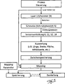
In Zeichnungsfigur
Ausgehend von einem Laser
Der Laser
Schließlich werden die zur Evaluierung der Bauteilqualität erfassten Sensorwerte zusammen mit den die Sensorwerte im Bauteil
In Zeichnungsfigur
BezugszeichenlisteLIST OF REFERENCE NUMBERS
- 11
- Bauteilcomponent
- 22
- Schichtlayer
- 33
- Strahlungradiation
- 44
- Baumaterialbuilding materials
- 55
- Schmelzbereichmelting range
- 66
- Sensorvorrichtungsensor device
- 77
- Laserlaser
- 88th
- halbreflektierender Spiegelsemi-reflective mirror
- 99
- Scannerscanner
- 1010
- Strahlenteilerbeamsplitter
- 1111
- Kameracamera
- 1212
- Fotodiodephotodiode
- 1313
- Trägercarrier
- 1414
- Basisplattebaseplate
- 1515
- BeschichtereinrichtungBeschichtereinrichtung
- 1616
- Spiegelmirror
- 1717
- Spiegelmirror
- 1818
- Sensorvorrichtungsensor device
- 1919
- Prozessorprocessor
- 2020
- SpeicherStorage
- 2121
- StrahlmanipulationseinrichtungBeam manipulation device
- 2222
-
Controller v.
21 Controller v.21 - 2323
- Datenverknüpfungs-/DatenzuordnungseinheitDatenverknüpfungs- / data allocation unit
- 2424
-
Stellmotor v.
13 Actuator v.13 - 2525
-
Stellmotor v.
26 Actuator v.26 - 2626
- Dosierkammermetering
- 2727
- Steuermodulcontrol module
- 2828
- DatenverarbeitungsanlageData processing system
- 2929
- Visualisierungseinrichtungvisualiser
ZITATE ENTHALTEN IN DER BESCHREIBUNG QUOTES INCLUDE IN THE DESCRIPTION
Diese Liste der vom Anmelder aufgeführten Dokumente wurde automatisiert erzeugt und ist ausschließlich zur besseren Information des Lesers aufgenommen. Die Liste ist nicht Bestandteil der deutschen Patent- bzw. Gebrauchsmusteranmeldung. Das DPMA übernimmt keinerlei Haftung für etwaige Fehler oder Auslassungen.This list of the documents listed by the applicant has been generated automatically and is included solely for the better information of the reader. The list is not part of the German patent or utility model application. The DPMA assumes no liability for any errors or omissions.
Zitierte PatentliteraturCited patent literature
- WO 2007/147221 [0002] WO 2007/147221 [0002]
- WO 2007/147221 A1 [0019] WO 2007/147221 A1 [0019]
Claims (13)
Priority Applications (12)
| Application Number | Priority Date | Filing Date | Title |
|---|---|---|---|
| DE202010010771U DE202010010771U1 (en) | 2010-07-28 | 2010-07-28 | Laser melting apparatus for producing a three-dimensional component |
| CN201180036741.XA CN103025507B (en) | 2010-07-28 | 2011-05-19 | For the manufacture of the method for three-dimensional structure |
| RU2013108952/08A RU2559717C2 (en) | 2010-07-28 | 2011-05-19 | Method of producing 3d construction parts |
| EP11779556.7A EP2598313B1 (en) | 2010-07-28 | 2011-05-19 | Method and apparatus for producing a three-dimensional component |
| ES11779556.7T ES2550670T3 (en) | 2010-07-28 | 2011-05-19 | Procedure and device for manufacturing a three-dimensional construction element |
| PCT/DE2011/001088 WO2012019577A2 (en) | 2010-07-28 | 2011-05-19 | Method for producing a three-dimensional component |
| US13/812,446 US10759117B2 (en) | 2010-07-28 | 2011-05-19 | Method for producing a three-dimensional component |
| JP2013520966A JP5946449B2 (en) | 2010-07-28 | 2011-05-19 | Manufacturing method of 3D parts |
| US15/904,272 US10265912B2 (en) | 2010-07-28 | 2018-02-23 | Method for producing a three-dimensional component |
| US16/290,942 US11701740B2 (en) | 2010-07-28 | 2019-03-03 | Method for producing a three-dimensional component |
| US17/003,424 US11292060B2 (en) | 2010-07-28 | 2020-08-26 | Method for producing a three-dimensional component |
| US17/688,130 US11904413B2 (en) | 2010-07-28 | 2022-03-07 | Method for producing a three-dimensional component |
Applications Claiming Priority (1)
| Application Number | Priority Date | Filing Date | Title |
|---|---|---|---|
| DE202010010771U DE202010010771U1 (en) | 2010-07-28 | 2010-07-28 | Laser melting apparatus for producing a three-dimensional component |
Publications (1)
| Publication Number | Publication Date |
|---|---|
| DE202010010771U1 true DE202010010771U1 (en) | 2011-11-14 |
Family
ID=44913133
Family Applications (1)
| Application Number | Title | Priority Date | Filing Date |
|---|---|---|---|
| DE202010010771U Expired - Lifetime DE202010010771U1 (en) | 2010-07-28 | 2010-07-28 | Laser melting apparatus for producing a three-dimensional component |
Country Status (8)
| Country | Link |
|---|---|
| US (5) | US10759117B2 (en) |
| EP (1) | EP2598313B1 (en) |
| JP (1) | JP5946449B2 (en) |
| CN (1) | CN103025507B (en) |
| DE (1) | DE202010010771U1 (en) |
| ES (1) | ES2550670T3 (en) |
| RU (1) | RU2559717C2 (en) |
| WO (1) | WO2012019577A2 (en) |
Cited By (18)
| Publication number | Priority date | Publication date | Assignee | Title |
|---|---|---|---|---|
| DE102012221218A1 (en) | 2011-11-22 | 2013-05-23 | Leibniz-Institut Für Festkörper- Und Werkstoffforschung Dresden E.V. | Device, useful for quality assurance of products manufactured by laser beam processing, includes laser beam processing apparatus, laser beam source, deflecting unit, and unit for determining and recording temperature at processing position |
| EP2666612A1 (en) * | 2012-05-25 | 2013-11-27 | MTU Aero Engines GmbH | Method and device for forming at least one three-dimensional component |
| DE102013201629A1 (en) * | 2013-01-31 | 2014-07-31 | MTU Aero Engines AG | Generative and layer-wise production of component by e.g. laser, comprises layer-by-layer melting of metal powder located in space of component by laser, where energy required for melting is regulated depending on position of component |
| DE102013003937A1 (en) | 2013-03-08 | 2014-09-11 | Cl Schutzrechtsverwaltungs Gmbh | Method for assessing the structural quality of three-dimensional components |
| WO2015032974A1 (en) * | 2013-09-09 | 2015-03-12 | Compagnie Generale Des Etablissements Michelin | Device for depositing a bed of powder on a surface, said device being provided with an electromagnetic-response probe, and corresponding method |
| DE102015000103A1 (en) | 2015-01-14 | 2016-07-14 | Cl Schutzrechtsverwaltungs Gmbh | Method for producing three-dimensional objects |
| DE102015000102A1 (en) | 2015-01-14 | 2016-07-14 | Cl Schutzrechtsverwaltungs Gmbh | Device for the generative production of three-dimensional components |
| DE102015113700A1 (en) * | 2015-04-22 | 2016-10-27 | Cl Schutzrechtsverwaltungs Gmbh | Method for producing a three-dimensional component |
| WO2018019567A1 (en) * | 2016-07-25 | 2018-02-01 | Eos Gmbh Electro Optical Systems | Method and device for determining component quality |
| CN108068314A (en) * | 2016-11-17 | 2018-05-25 | 三纬国际立体列印科技股份有限公司 | Color three dimension object cuts layer Method of printing and color three dimension print system |
| US10043257B2 (en) | 2015-03-17 | 2018-08-07 | MTU Aero Engines AG | Method and device for the quality evaluation of a component produced by means of an additive manufacturing method |
| EP3650142A1 (en) * | 2018-11-09 | 2020-05-13 | General Electric Company | Melt pool monitoring system and method for detecting errors in an additive manufacturing process |
| GB2538410B (en) * | 2014-01-16 | 2020-06-03 | Hewlett Packard Development Co | Generating three-dimensional objects |
| DE102019200795A1 (en) * | 2019-01-23 | 2020-07-23 | Robert Bosch Gmbh | Surface detection method for laser beam melting |
| US11167475B2 (en) | 2014-01-16 | 2021-11-09 | Hewlett-Packard Development Company, L.P. | Generating three-dimensional objects |
| DE102020127575A1 (en) | 2020-10-20 | 2022-04-21 | Trumpf Laser Gmbh | Laser processing machine with at least one protective device against X-ray shadowing |
| US11618217B2 (en) | 2014-01-16 | 2023-04-04 | Hewlett-Packard Development Company, L.P. | Generating three-dimensional objects |
| US11673314B2 (en) | 2014-01-16 | 2023-06-13 | Hewlett-Packard Development Company, L.P. | Generating three-dimensional objects |
Families Citing this family (99)
| Publication number | Priority date | Publication date | Assignee | Title |
|---|---|---|---|---|
| GB0816308D0 (en) | 2008-09-05 | 2008-10-15 | Mtt Technologies Ltd | Optical module |
| DE202010010771U1 (en) | 2010-07-28 | 2011-11-14 | Cl Schutzrechtsverwaltungs Gmbh | Laser melting apparatus for producing a three-dimensional component |
| TWI448732B (en) * | 2012-05-03 | 2014-08-11 | Young Optics Inc | Three-dimensional printing apparatus |
| GB201216636D0 (en) * | 2012-09-18 | 2012-10-31 | Blueprinter Aps | Powder feed mechanism for a three-dimensional printer |
| DE102013003760A1 (en) * | 2013-03-06 | 2014-09-11 | MTU Aero Engines AG | Method and device for quality evaluation of a component produced by means of a generative laser sintering and / or laser melting process |
| JP6581079B2 (en) * | 2013-06-26 | 2019-09-25 | レニショウ パブリック リミテッド カンパニーRenishaw Public Limited Company | Method and apparatus for generating geometric data for use in additive manufacturing |
| US10821508B2 (en) * | 2013-08-15 | 2020-11-03 | General Electric Company | System and methods for enhancing the build parameters of a component |
| DE102013217422A1 (en) | 2013-09-02 | 2015-03-05 | Carl Zeiss Industrielle Messtechnik Gmbh | Coordinate measuring machine and method for measuring and at least partially producing a workpiece |
| GB201316815D0 (en) | 2013-09-23 | 2013-11-06 | Renishaw Plc | Additive manufacturing apparatus and method |
| DE102013017792A1 (en) | 2013-10-28 | 2015-04-30 | Cl Schutzrechtsverwaltungs Gmbh | Method for producing a three-dimensional component |
| DE102013224649A1 (en) * | 2013-11-29 | 2015-06-03 | Sauer Gmbh Lasertec | Machine tool, measuring device, method for creating work data, build-up welding method, workpiece temperature control device |
| RU2595072C2 (en) * | 2014-02-14 | 2016-08-20 | Юрий Александрович Чивель | Method of controlling process of selective laser sintering of 3d articles from powders and device therefor |
| WO2015196149A1 (en) | 2014-06-20 | 2015-12-23 | Velo3D, Inc. | Apparatuses, systems and methods for three-dimensional printing |
| KR102359288B1 (en) | 2014-08-20 | 2022-02-04 | 에체-따르 에세.아. | Method and system for additive manufacturing using a light beam |
| DE102014216567A1 (en) | 2014-08-21 | 2016-02-25 | MTU Aero Engines AG | Method for determining the quality of an additively manufactured component |
| US9757902B2 (en) | 2014-09-02 | 2017-09-12 | Product Innovation and Engineering L.L.C. | Additive layering method using improved build description |
| US9573224B2 (en) | 2014-09-02 | 2017-02-21 | Product Innovation & Engineering, LLC | System and method for determining beam power level along an additive deposition path |
| US20170274599A1 (en) * | 2014-09-19 | 2017-09-28 | Kabushiki Kaisha Toshiba | Additive manufacturing apparatus and additive manufacturing method |
| US10112262B2 (en) * | 2014-10-28 | 2018-10-30 | General Electric Company | System and methods for real-time enhancement of build parameters of a component |
| JP6843756B2 (en) * | 2014-11-24 | 2021-03-17 | アディティブ インダストリーズ ビー.ブイ. | Equipment for manufacturing objects by laminated modeling |
| US10632566B2 (en) | 2014-12-02 | 2020-04-28 | Product Innovation and Engineering L.L.C. | System and method for controlling the input energy from an energy point source during metal processing |
| EP3229996A4 (en) * | 2014-12-12 | 2018-09-05 | Velo3d Inc. | Feedback control systems for three-dimensional printing |
| JP6203704B2 (en) * | 2014-12-18 | 2017-09-27 | 株式会社ソディック | Control system for additive manufacturing equipment |
| DE102015000100A1 (en) * | 2015-01-14 | 2016-07-14 | Cl Schutzrechtsverwaltungs Gmbh | Method for the production of three-dimensional components |
| CN104760297A (en) * | 2015-04-10 | 2015-07-08 | 钱波 | Nylon sintering shaping machine with auxiliary power spreading device |
| EP3095591B1 (en) | 2015-05-19 | 2019-11-13 | MTU Aero Engines GmbH | Method and device for detecting at least sections of a contour of a layer of an object obtainable by additive processing |
| US20180169948A1 (en) * | 2015-06-12 | 2018-06-21 | Materialise N.V. | System and method for ensuring consistency in additive manufacturing using thermal imaging |
| US20170087634A1 (en) | 2015-09-30 | 2017-03-30 | General Electric Company | System and method for additive manufacturing process control |
| US10150184B2 (en) * | 2015-10-21 | 2018-12-11 | Siemens Energy, Inc. | Method of forming a cladding layer having an integral channel |
| KR101726833B1 (en) * | 2015-10-28 | 2017-04-14 | 조선대학교산학협력단 | Rapid manufacturing process of ferrous and non-ferrous parts using plasma electron beam |
| WO2017075258A1 (en) * | 2015-10-30 | 2017-05-04 | Seurat Technologies, Inc. | Additive manufacturing system and method |
| US10500675B2 (en) | 2015-11-02 | 2019-12-10 | General Electric Company | Additive manufacturing systems including an imaging device and methods of operating such systems |
| WO2017079091A1 (en) | 2015-11-06 | 2017-05-11 | Velo3D, Inc. | Adept three-dimensional printing |
| CN108349005B (en) * | 2015-11-16 | 2021-08-31 | 瑞尼斯豪公司 | Machine control for additive manufacturing processes and apparatus |
| KR20180082492A (en) * | 2015-11-16 | 2018-07-18 | 머티어리얼리스 엔브이 | Error detection in stacking process |
| WO2017085470A1 (en) | 2015-11-16 | 2017-05-26 | Renishaw Plc | Module for additive manufacturing apparatus and method |
| DE102015223719A1 (en) * | 2015-11-30 | 2017-06-01 | Eos Gmbh Electro Optical Systems | Method and device for building material requirement determination |
| WO2017094072A1 (en) * | 2015-11-30 | 2017-06-08 | オリンパス株式会社 | Optical element manufacturing apparatus and optical element manufacturing method |
| EP3386662A4 (en) | 2015-12-10 | 2019-11-13 | Velo3d Inc. | Skillful three-dimensional printing |
| DE102016200043A1 (en) * | 2016-01-05 | 2017-07-06 | Eos Gmbh Electro Optical Systems | Method for calibrating a device for producing a three-dimensional object |
| DE102016200324A1 (en) * | 2016-01-14 | 2017-07-20 | MTU Aero Engines AG | Method for determining a concentration of at least one material in a powder for an additive manufacturing process |
| CN108883575A (en) | 2016-02-18 | 2018-11-23 | 维洛3D公司 | Accurate 3 D-printing |
| CN105750544B (en) * | 2016-03-03 | 2017-11-24 | 西安铂力特增材技术股份有限公司 | A kind of laser head auto-focusing positioner and its focusing localization method |
| US11182517B2 (en) * | 2016-03-18 | 2021-11-23 | Hewlett-Packard Development Company, L.P. | Modification data for additive manufacturing |
| JP6730452B2 (en) * | 2016-05-12 | 2020-07-29 | ヒューレット−パッカード デベロップメント カンパニー エル.ピー.Hewlett‐Packard Development Company, L.P. | 3D object part quality prediction |
| EP3243583B1 (en) * | 2016-05-13 | 2019-05-08 | SLM Solutions Group AG | Apparatus and method for associating a position in a construction data set with a position in a building section of the apparatus |
| US11691343B2 (en) | 2016-06-29 | 2023-07-04 | Velo3D, Inc. | Three-dimensional printing and three-dimensional printers |
| US10286452B2 (en) | 2016-06-29 | 2019-05-14 | Velo3D, Inc. | Three-dimensional printing and three-dimensional printers |
| DE102016212063A1 (en) | 2016-07-01 | 2018-01-04 | Eos Gmbh Electro Optical Systems | Apparatus and method for irradiation control in a device for producing a three-dimensional object |
| US20180029306A1 (en) * | 2016-07-26 | 2018-02-01 | General Electric Company | Methods and ghost supports for additive manufacturing |
| DE102016114053A1 (en) * | 2016-07-29 | 2018-02-01 | Cl Schutzrechtsverwaltungs Gmbh | Powder module for a device for the additive production of three-dimensional objects |
| JP7065351B2 (en) * | 2016-09-02 | 2022-05-12 | パナソニックIpマネジメント株式会社 | Manufacturing method of 3D shaped object |
| BE1024495B1 (en) * | 2016-09-27 | 2018-03-13 | Materialise N.V. | ENERGY DENSITY CLASSIFICATION IN ADDITIVE PRODUCTION ENVIRONMENTS |
| US20180126461A1 (en) | 2016-11-07 | 2018-05-10 | Velo3D, Inc. | Gas flow in three-dimensional printing |
| EP3538295B1 (en) * | 2016-11-14 | 2023-05-24 | Renishaw PLC | Localising sensor data collected during additive manufacturing |
| DE102016121803A1 (en) | 2016-11-14 | 2018-05-17 | Cl Schutzrechtsverwaltungs Gmbh | Device for the additive production of three-dimensional objects |
| US20180186081A1 (en) | 2017-01-05 | 2018-07-05 | Velo3D, Inc. | Optics in three-dimensional printing |
| US10357829B2 (en) | 2017-03-02 | 2019-07-23 | Velo3D, Inc. | Three-dimensional printing of three-dimensional objects |
| DE102017104506A1 (en) * | 2017-03-03 | 2018-09-06 | Cl Schutzrechtsverwaltungs Gmbh | Device for the additive production of three-dimensional objects |
| JP6415004B2 (en) * | 2017-03-14 | 2018-10-31 | 株式会社ソディック | Additive manufacturing equipment |
| US20180264590A1 (en) * | 2017-03-15 | 2018-09-20 | Jentek Sensors, Inc. | In situ additive manufacturing process sensing and control including post process ndt |
| US20180281237A1 (en) | 2017-03-28 | 2018-10-04 | Velo3D, Inc. | Material manipulation in three-dimensional printing |
| WO2018190807A1 (en) * | 2017-04-11 | 2018-10-18 | Hewlett-Packard Development Company, L.P. | Fusing build material |
| US20210209484A1 (en) * | 2017-04-21 | 2021-07-08 | Hewlett-Packard Development Company, L.P. | Relating print coverage matrices to object property matrice |
| DE102017108534A1 (en) | 2017-04-21 | 2018-10-25 | Eos Gmbh Electro Optical Systems | Control of an additive manufacturing process |
| EP3431210B1 (en) | 2017-07-21 | 2024-04-17 | Concept Laser GmbH | Powder module |
| EP3446855B1 (en) * | 2017-08-25 | 2021-11-24 | CL Schutzrechtsverwaltungs GmbH | Apparatus for additively manufacturing of three-dimensional objects |
| GB201718597D0 (en) * | 2017-11-10 | 2017-12-27 | Renishaw Plc | Spatial mapping of sensor data collected during additive manufacturing |
| DE202017005861U1 (en) | 2017-11-10 | 2018-02-21 | O.R. Lasertechnologie Gmbh | Device with a milling device for the production and surface treatment of a three-dimensional object |
| DE202017005866U1 (en) | 2017-11-10 | 2018-02-21 | O.R. Lasertechnologie Gmbh | Device for the production and surface treatment of a three-dimensional object |
| DE202017005855U1 (en) | 2017-11-10 | 2018-02-28 | O.R. Lasertechnologie Gmbh | Device having a first and a second carrier device for the production and surface treatment of a three-dimensional object |
| DE102017010474A1 (en) | 2017-11-10 | 2019-05-16 | O.R. Lasertechnologie Gmbh | Device for the production and surface treatment of a three-dimensional object |
| US10272525B1 (en) | 2017-12-27 | 2019-04-30 | Velo3D, Inc. | Three-dimensional printing systems and methods of their use |
| DE102018200566B4 (en) * | 2018-01-15 | 2021-07-15 | Fraunhofer-Gesellschaft zur Förderung der angewandten Forschung e.V. | System and method for monitoring the manufacturing accuracy in the additive manufacturing of three-dimensional components |
| US10144176B1 (en) | 2018-01-15 | 2018-12-04 | Velo3D, Inc. | Three-dimensional printing systems and methods of their use |
| US10914677B2 (en) | 2018-04-24 | 2021-02-09 | General Electric Company | System and method for calibrating a melt pool monitoring system of an additive manufacturing machine |
| US11426818B2 (en) | 2018-08-10 | 2022-08-30 | The Research Foundation for the State University | Additive manufacturing processes and additively manufactured products |
| GB201818385D0 (en) | 2018-11-12 | 2018-12-26 | Renishaw Plc | Additive manufacturing |
| US10962507B2 (en) | 2018-11-28 | 2021-03-30 | General Electric Company | System and method for calibrating an acoustic monitoring system of an additive manufacturing machine |
| US11285671B2 (en) | 2018-12-13 | 2022-03-29 | General Electric Company | Method for melt pool monitoring using Green's theorem |
| US10894364B2 (en) | 2018-12-13 | 2021-01-19 | General Electric Company | Method for melt pool monitoring using geometric length |
| US11020907B2 (en) | 2018-12-13 | 2021-06-01 | General Electric Company | Method for melt pool monitoring using fractal dimensions |
| US10828837B2 (en) | 2018-12-13 | 2020-11-10 | General Electric Company | Method for melt pool monitoring using algebraic connectivity |
| US10828836B2 (en) | 2018-12-13 | 2020-11-10 | General Electric Company | Method for melt pool monitoring |
| EP3702158A1 (en) | 2019-02-28 | 2020-09-02 | Renishaw PLC | Improvements in or relating to on-axis melt pool sensors in an additive manufacturing apparatus |
| WO2021001878A1 (en) | 2019-07-01 | 2021-01-07 | 株式会社ニコン | Molding device |
| US20220212263A1 (en) | 2019-07-02 | 2022-07-07 | Nikon Corporation | Non-coaxial rotating turntables for additive manufacturing |
| KR102262058B1 (en) * | 2019-08-21 | 2021-06-09 | 한국조선해양 주식회사 | Method for setting of process optimazation of three-dimensional printer |
| CN114514082B (en) * | 2019-09-25 | 2023-11-03 | Slm方案集团股份公司 | Device and method for analyzing sensor data, device and storage medium |
| US11878365B2 (en) | 2019-11-20 | 2024-01-23 | Concept Laser Gmbh | Focus adjustment and laser beam caustic estimation via frequency analysis of time traces and 2D raster scan data |
| CN111873421A (en) * | 2020-06-29 | 2020-11-03 | 北京科技大学 | Lower powder feeding type gradient powder layer laying device and powder layer laying method |
| CN111730860B (en) * | 2020-08-18 | 2022-02-18 | 连灿鑫 | Material increasing and decreasing composite machining center for composite section |
| US11839915B2 (en) | 2021-01-20 | 2023-12-12 | Product Innovation and Engineering LLC | System and method for determining beam power level along an additive deposition path |
| US20220272207A1 (en) * | 2021-02-24 | 2022-08-25 | General Electric Company | Automated beam scan calibration, alignment, and adjustment |
| US11915405B2 (en) | 2021-03-16 | 2024-02-27 | Applied Optimization, Inc. | Additive manufacturing process monitoring |
| WO2022215056A1 (en) | 2021-04-09 | 2022-10-13 | Inegi - Instituto De Ciência E Inovação Em Engenharia Mecânica E Engenharia Industrial | Device and method for adaptive control of a fused deposition modeling printer using thermography |
| EP4173741A1 (en) | 2021-10-28 | 2023-05-03 | Fraunhofer-Gesellschaft zur Förderung der angewandten Forschung e.V. | Method and device for monitoring a laser processing process by means of speckle photometry |
| DE102021133930B3 (en) | 2021-12-20 | 2023-06-22 | Universität Stuttgart, Körperschaft Des Öffentlichen Rechts | Method for determining a temperature distribution in and/or directly around a melt pool during laser or electron beam melting |
| TWI811926B (en) * | 2021-12-28 | 2023-08-11 | 國家中山科學研究院 | Additive Manufacturing Dust Surface Monitoring System |
Citations (1)
| Publication number | Priority date | Publication date | Assignee | Title |
|---|---|---|---|---|
| WO2007147221A1 (en) | 2006-06-20 | 2007-12-27 | Katholieke Universiteit Leuven | Procedure and apparatus for in-situ monitoring and feedback control of selective laser powder processing |
Family Cites Families (24)
| Publication number | Priority date | Publication date | Assignee | Title |
|---|---|---|---|---|
| US5382770A (en) | 1993-01-14 | 1995-01-17 | Reliant Laser Corporation | Mirror-based laser-processing system with visual tracking and position control of a moving laser spot |
| US5427733A (en) | 1993-10-20 | 1995-06-27 | United Technologies Corporation | Method for performing temperature-controlled laser sintering |
| US6122564A (en) | 1998-06-30 | 2000-09-19 | Koch; Justin | Apparatus and methods for monitoring and controlling multi-layer laser cladding |
| US6580959B1 (en) | 1999-03-11 | 2003-06-17 | Precision Optical Manufacturing (Pom) | System and method for remote direct material deposition |
| DE10007711C1 (en) * | 2000-02-19 | 2001-08-16 | Daimler Chrysler Ag | Apparatus for sintering a powder used in rapid prototyping process comprises device for producing laser beam, device for determining powder temperature, device for regulating laser beam, and device for compensating position-dependent errors |
| SE521124C2 (en) * | 2000-04-27 | 2003-09-30 | Arcam Ab | Device and method for making a three-dimensional product |
| JP2001352562A (en) * | 2000-06-07 | 2001-12-21 | Minolta Co Ltd | Stereoscopic data processing system |
| DE10120251B4 (en) | 2001-04-25 | 2006-03-23 | Precitec Kg | Method and sensor device for monitoring a laser processing operation to be performed on a workpiece and laser processing head with such a sensor device |
| WO2003042895A1 (en) | 2001-11-17 | 2003-05-22 | Insstek Inc. | Method and system for real-time monitoring and controlling height of deposit by using image photographing and image processing technology in laser cladding and laser-aided direct metal manufacturing process |
| DE10157647C5 (en) * | 2001-11-26 | 2012-03-08 | Cl Schutzrechtsverwaltungs Gmbh | Method for producing three-dimensional workpieces in a laser material processing system or a stereolithography system |
| DE10236697A1 (en) | 2002-08-09 | 2004-02-26 | Eos Gmbh Electro Optical Systems | Method and device for producing a three-dimensional object by means of sintering |
| ATE461777T1 (en) | 2002-08-28 | 2010-04-15 | P O M Group | MULTI-LAYER DMD PROCESS WITH A SYSTEM INDEPENDENT OF THE GEOMETRY OF THE WORKPIECE FOR CONTROLLING, IN REAL TIME AND IN A CLOSED LOOP, THE WELDING POOL TEMPERATURE |
| EP1396556A1 (en) | 2002-09-06 | 2004-03-10 | ALSTOM (Switzerland) Ltd | Method for controlling the microstructure of a laser metal formed hard layer |
| JP2004223789A (en) * | 2003-01-21 | 2004-08-12 | Seiko Instruments Inc | Optical micro-shaping apparatus with observation function |
| DE10310385B4 (en) | 2003-03-07 | 2006-09-21 | Daimlerchrysler Ag | Method for the production of three-dimensional bodies by means of powder-based layer-building methods |
| US6815636B2 (en) | 2003-04-09 | 2004-11-09 | 3D Systems, Inc. | Sintering using thermal image feedback |
| WO2004109871A2 (en) | 2003-06-03 | 2004-12-16 | Applied Thermal Sciences, Inc. | Laser-weld process control system and method |
| JP2005018532A (en) * | 2003-06-27 | 2005-01-20 | Maiku:Kk | Method for producing molding die and food die |
| DE102005025348B4 (en) * | 2005-05-31 | 2007-08-02 | Trumpf Werkzeugmaschinen Gmbh + Co. Kg | Process for producing a shaped body and sensor unit for its implementation |
| DE602006007580D1 (en) * | 2006-08-07 | 2009-08-13 | Lvd Co | Arrangement and method for on-line monitoring of the laser process of a workpiece using a heat chamber detector and a tilted mirror |
| JP4916392B2 (en) | 2007-06-26 | 2012-04-11 | パナソニック株式会社 | Manufacturing method and manufacturing apparatus for three-dimensional shaped object |
| DE102007056984A1 (en) * | 2007-11-27 | 2009-05-28 | Eos Gmbh Electro Optical Systems | Method for producing a three-dimensional object by means of laser sintering |
| US8723078B2 (en) | 2008-11-21 | 2014-05-13 | The Regents Of The University Of Michigan | Monitoring of a welding process |
| DE202010010771U1 (en) | 2010-07-28 | 2011-11-14 | Cl Schutzrechtsverwaltungs Gmbh | Laser melting apparatus for producing a three-dimensional component |
-
2010
- 2010-07-28 DE DE202010010771U patent/DE202010010771U1/en not_active Expired - Lifetime
-
2011
- 2011-05-19 US US13/812,446 patent/US10759117B2/en active Active
- 2011-05-19 WO PCT/DE2011/001088 patent/WO2012019577A2/en active Application Filing
- 2011-05-19 RU RU2013108952/08A patent/RU2559717C2/en active
- 2011-05-19 ES ES11779556.7T patent/ES2550670T3/en active Active
- 2011-05-19 EP EP11779556.7A patent/EP2598313B1/en not_active Revoked
- 2011-05-19 JP JP2013520966A patent/JP5946449B2/en active Active
- 2011-05-19 CN CN201180036741.XA patent/CN103025507B/en active Active
-
2018
- 2018-02-23 US US15/904,272 patent/US10265912B2/en active Active
-
2019
- 2019-03-03 US US16/290,942 patent/US11701740B2/en active Active
-
2020
- 2020-08-26 US US17/003,424 patent/US11292060B2/en active Active
-
2022
- 2022-03-07 US US17/688,130 patent/US11904413B2/en active Active
Patent Citations (1)
| Publication number | Priority date | Publication date | Assignee | Title |
|---|---|---|---|---|
| WO2007147221A1 (en) | 2006-06-20 | 2007-12-27 | Katholieke Universiteit Leuven | Procedure and apparatus for in-situ monitoring and feedback control of selective laser powder processing |
Cited By (35)
| Publication number | Priority date | Publication date | Assignee | Title |
|---|---|---|---|---|
| DE102012221218A1 (en) | 2011-11-22 | 2013-05-23 | Leibniz-Institut Für Festkörper- Und Werkstoffforschung Dresden E.V. | Device, useful for quality assurance of products manufactured by laser beam processing, includes laser beam processing apparatus, laser beam source, deflecting unit, and unit for determining and recording temperature at processing position |
| EP2666612A1 (en) * | 2012-05-25 | 2013-11-27 | MTU Aero Engines GmbH | Method and device for forming at least one three-dimensional component |
| EP2666612B1 (en) | 2012-05-25 | 2018-11-28 | MTU Aero Engines AG | Method and device for imaging at least one three-dimensional component |
| DE102013201629A1 (en) * | 2013-01-31 | 2014-07-31 | MTU Aero Engines AG | Generative and layer-wise production of component by e.g. laser, comprises layer-by-layer melting of metal powder located in space of component by laser, where energy required for melting is regulated depending on position of component |
| WO2014135137A2 (en) | 2013-03-08 | 2014-09-12 | Cl Schutzrechtsverwaltungs Gmbh | Method for assessing the structural quality of three-dimensional components |
| EP3760367A1 (en) * | 2013-03-08 | 2021-01-06 | CL Schutzrechtsverwaltungs GmbH | Method for assessing the structural quality of three-dimensional components |
| EP3492215B1 (en) | 2013-03-08 | 2020-09-23 | CL Schutzrechtsverwaltungs GmbH | Method for assessing the structural quality of three-dimensional components |
| EP3492215A1 (en) | 2013-03-08 | 2019-06-05 | CL Schutzrechtsverwaltungs GmbH | Method for assessing the structural quality of three-dimensional components |
| US10722985B2 (en) | 2013-03-08 | 2020-07-28 | Concept Laser Gmbh | Method for assessing the structural quality of three-dimensional components |
| DE102013003937A1 (en) | 2013-03-08 | 2014-09-11 | Cl Schutzrechtsverwaltungs Gmbh | Method for assessing the structural quality of three-dimensional components |
| WO2014135137A3 (en) * | 2013-03-08 | 2014-10-30 | Cl Schutzrechtsverwaltungs Gmbh | Method for assessing the structural quality of three-dimensional components |
| US10926525B2 (en) | 2013-09-09 | 2021-02-23 | Compagnie Generale Des Etablissements Michelin | Device for depositing a bed of powder on a surface, said device being provided with an electromagnetic-response probe, and corresponding method |
| FR3010334A1 (en) * | 2013-09-09 | 2015-03-13 | Michelin & Cie | POWDER BED DEPOSITION DEVICE ON SURFACE PROVIDED WITH AN ELECTROMAGNETIC RESPONSE PROBE, AND CORRESPONDING METHOD |
| WO2015032974A1 (en) * | 2013-09-09 | 2015-03-12 | Compagnie Generale Des Etablissements Michelin | Device for depositing a bed of powder on a surface, said device being provided with an electromagnetic-response probe, and corresponding method |
| US11618217B2 (en) | 2014-01-16 | 2023-04-04 | Hewlett-Packard Development Company, L.P. | Generating three-dimensional objects |
| US11167475B2 (en) | 2014-01-16 | 2021-11-09 | Hewlett-Packard Development Company, L.P. | Generating three-dimensional objects |
| US11673314B2 (en) | 2014-01-16 | 2023-06-13 | Hewlett-Packard Development Company, L.P. | Generating three-dimensional objects |
| US11679560B2 (en) | 2014-01-16 | 2023-06-20 | Hewlett-Packard Development Company, L.P. | Generating a three-dimensional object |
| GB2538410B (en) * | 2014-01-16 | 2020-06-03 | Hewlett Packard Development Co | Generating three-dimensional objects |
| DE102015000103A1 (en) | 2015-01-14 | 2016-07-14 | Cl Schutzrechtsverwaltungs Gmbh | Method for producing three-dimensional objects |
| DE102015000102A1 (en) | 2015-01-14 | 2016-07-14 | Cl Schutzrechtsverwaltungs Gmbh | Device for the generative production of three-dimensional components |
| US11179806B2 (en) | 2015-01-14 | 2021-11-23 | Concept Laser Gmbh | Device for the additive production of three-dimensional components |
| WO2016113253A1 (en) * | 2015-01-14 | 2016-07-21 | Cl Schutzrechtsverwaltungs Gmbh | Device for the additive production of three-dimensional components |
| US10043257B2 (en) | 2015-03-17 | 2018-08-07 | MTU Aero Engines AG | Method and device for the quality evaluation of a component produced by means of an additive manufacturing method |
| DE102015113700A1 (en) * | 2015-04-22 | 2016-10-27 | Cl Schutzrechtsverwaltungs Gmbh | Method for producing a three-dimensional component |
| US11919243B2 (en) | 2015-04-22 | 2024-03-05 | Concept Laser Gmbh | Method for producing a three-dimensional component |
| US11247400B2 (en) | 2015-04-22 | 2022-02-15 | Concept Laser Gmbh | Method for producing a three-dimensional component |
| US11141923B2 (en) | 2016-07-25 | 2021-10-12 | Eos Gmbh Electro Optical Systems | Method and device of detecting part quality of a three dimensional manufacturing object |
| WO2018019567A1 (en) * | 2016-07-25 | 2018-02-01 | Eos Gmbh Electro Optical Systems | Method and device for determining component quality |
| CN108068314A (en) * | 2016-11-17 | 2018-05-25 | 三纬国际立体列印科技股份有限公司 | Color three dimension object cuts layer Method of printing and color three dimension print system |
| US11559854B2 (en) | 2018-11-09 | 2023-01-24 | General Electric Company | Methods for detecting errors in an additive manufacturing process |
| US11806925B2 (en) | 2018-11-09 | 2023-11-07 | General Electric Company | Additive manufacturing process |
| EP3650142A1 (en) * | 2018-11-09 | 2020-05-13 | General Electric Company | Melt pool monitoring system and method for detecting errors in an additive manufacturing process |
| DE102019200795A1 (en) * | 2019-01-23 | 2020-07-23 | Robert Bosch Gmbh | Surface detection method for laser beam melting |
| DE102020127575A1 (en) | 2020-10-20 | 2022-04-21 | Trumpf Laser Gmbh | Laser processing machine with at least one protective device against X-ray shadowing |
Also Published As
| Publication number | Publication date |
|---|---|
| RU2013108952A (en) | 2014-09-10 |
| US11292060B2 (en) | 2022-04-05 |
| US20180186078A1 (en) | 2018-07-05 |
| EP2598313B1 (en) | 2015-08-12 |
| WO2012019577A3 (en) | 2012-05-31 |
| US10265912B2 (en) | 2019-04-23 |
| JP2013532592A (en) | 2013-08-19 |
| US20200391291A1 (en) | 2020-12-17 |
| WO2012019577A2 (en) | 2012-02-16 |
| US11701740B2 (en) | 2023-07-18 |
| CN103025507A (en) | 2013-04-03 |
| ES2550670T3 (en) | 2015-11-11 |
| US20130168902A1 (en) | 2013-07-04 |
| JP5946449B2 (en) | 2016-07-06 |
| EP2598313A2 (en) | 2013-06-05 |
| US20220184705A1 (en) | 2022-06-16 |
| US10759117B2 (en) | 2020-09-01 |
| US20190202129A1 (en) | 2019-07-04 |
| CN103025507B (en) | 2015-11-25 |
| RU2559717C2 (en) | 2015-08-10 |
| US11904413B2 (en) | 2024-02-20 |
Similar Documents
| Publication | Publication Date | Title |
|---|---|---|
| EP2598313B1 (en) | Method and apparatus for producing a three-dimensional component | |
| EP2942130B1 (en) | Apparatus and method for additive manufacturing of a device component | |
| DE102016011801A1 (en) | Method for calibrating a device for producing a three-dimensional object and device designed to carry out the method | |
| EP3383624B1 (en) | Method for calibrating a device for producing a three-dimensional object | |
| EP3245043B1 (en) | Device for the additive production of three-dimensional components | |
| EP3059076B1 (en) | Method and device for generating a three-dimensional object | |
| WO2018192833A1 (en) | Supervision of an additive manufacturing process | |
| EP3263317B1 (en) | Device and method for irradiation control in a device for producing a three-dimensional object | |
| WO2015010855A1 (en) | Device and method for producing a three-dimensional object layer by layer | |
| DE102010000473A1 (en) | Method for measuring an object | |
| EP2666612A1 (en) | Method and device for forming at least one three-dimensional component | |
| EP3441163A1 (en) | Device for additive manufacturing of at least one three-dimensional object | |
| DE102016014564A1 (en) | Measuring device for monitoring a machining process using measurement information acquired at different measuring positions | |
| DE102016201290A1 (en) | Method of quality assurance and device | |
| EP3362835B1 (en) | Exposure optical system and device for producing a three-dimensional object | |
| WO2017202818A1 (en) | Method and device for process monitoring during the additive manufacturing of components | |
| WO2020099323A1 (en) | Method for capturing a working region of a generative manufacturing device and manufacturing device for generative manufacturing of components made of a powder material | |
| EP3488305B1 (en) | Method and device for determining component quality | |
| DE102018204510A1 (en) | Computer-based method for providing control command data for an additive manufacturing device | |
| EP4054827B1 (en) | Method and apparatus for processing an optically reactive material | |
| DE102020212858A1 (en) | System for monitoring a layer construction process | |
| EP3335856B1 (en) | Exposure device for an apparatus for additive manufacturing of three-dimensional objects | |
| DE102018124208A1 (en) | Method and device for monitoring a machining process of a workpiece by means of a laser beam | |
| DE102020112635A1 (en) | Laser scanner system and method for processing a workpiece | |
| EP4337911A1 (en) | Measuring device, manufacturing device having a measuring device of this type, and method for operating a manufacturing device for the additive manufacturing of a component from a powder material |
Legal Events
| Date | Code | Title | Description |
|---|---|---|---|
| R207 | Utility model specification |
Effective date: 20120105 |
|
| R150 | Utility model maintained after payment of first maintenance fee after three years | ||
| R150 | Utility model maintained after payment of first maintenance fee after three years |
Effective date: 20130812 |
|
| R151 | Utility model maintained after payment of second maintenance fee after six years | ||
| R079 | Amendment of ipc main class |
Free format text: PREVIOUS MAIN CLASS: B29C0067000000 Ipc: B29C0064106000 |
|
| R152 | Utility model maintained after payment of third maintenance fee after eight years | ||
| R071 | Expiry of right |