US11529578B2 - Exhaust gas purification filter - Google Patents
Exhaust gas purification filter Download PDFInfo
- Publication number
- US11529578B2 US11529578B2 US17/647,732 US202217647732A US11529578B2 US 11529578 B2 US11529578 B2 US 11529578B2 US 202217647732 A US202217647732 A US 202217647732A US 11529578 B2 US11529578 B2 US 11529578B2
- Authority
- US
- United States
- Prior art keywords
- exhaust gas
- gas purification
- partition walls
- catalyst
- inflow side
- Prior art date
- Legal status (The legal status is an assumption and is not a legal conclusion. Google has not performed a legal analysis and makes no representation as to the accuracy of the status listed.)
- Active
Links
- 238000000746 purification Methods 0.000 title claims abstract description 84
- 239000003054 catalyst Substances 0.000 claims abstract description 100
- 238000005192 partition Methods 0.000 claims abstract description 64
- 239000011148 porous material Substances 0.000 claims abstract description 45
- 239000013618 particulate matter Substances 0.000 claims abstract description 41
- 239000000463 material Substances 0.000 claims abstract description 34
- 238000011144 upstream manufacturing Methods 0.000 claims abstract description 26
- 239000011248 coating agent Substances 0.000 claims abstract description 9
- 238000000576 coating method Methods 0.000 claims abstract description 9
- 238000002485 combustion reaction Methods 0.000 claims description 10
- 229910021536 Zeolite Inorganic materials 0.000 claims description 7
- HNPSIPDUKPIQMN-UHFFFAOYSA-N dioxosilane;oxo(oxoalumanyloxy)alumane Chemical compound O=[Si]=O.O=[Al]O[Al]=O HNPSIPDUKPIQMN-UHFFFAOYSA-N 0.000 claims description 7
- 239000010457 zeolite Substances 0.000 claims description 7
- 230000037361 pathway Effects 0.000 claims description 5
- 239000007789 gas Substances 0.000 description 81
- 230000000052 comparative effect Effects 0.000 description 14
- 239000004215 Carbon black (E152) Substances 0.000 description 10
- 229930195733 hydrocarbon Natural products 0.000 description 10
- 150000002430 hydrocarbons Chemical class 0.000 description 10
- 239000002002 slurry Substances 0.000 description 10
- CETPSERCERDGAM-UHFFFAOYSA-N ceric oxide Chemical compound O=[Ce]=O CETPSERCERDGAM-UHFFFAOYSA-N 0.000 description 9
- 229910000422 cerium(IV) oxide Inorganic materials 0.000 description 9
- 238000000034 method Methods 0.000 description 9
- MCMNRKCIXSYSNV-UHFFFAOYSA-N Zirconium dioxide Chemical compound O=[Zr]=O MCMNRKCIXSYSNV-UHFFFAOYSA-N 0.000 description 8
- QVGXLLKOCUKJST-UHFFFAOYSA-N atomic oxygen Chemical compound [O] QVGXLLKOCUKJST-UHFFFAOYSA-N 0.000 description 6
- 229910052751 metal Inorganic materials 0.000 description 6
- 239000002184 metal Substances 0.000 description 6
- 229910000510 noble metal Inorganic materials 0.000 description 6
- 229910052760 oxygen Inorganic materials 0.000 description 6
- 239000001301 oxygen Substances 0.000 description 6
- 238000007789 sealing Methods 0.000 description 6
- PNEYBMLMFCGWSK-UHFFFAOYSA-N aluminium oxide Inorganic materials [O-2].[O-2].[O-2].[Al+3].[Al+3] PNEYBMLMFCGWSK-UHFFFAOYSA-N 0.000 description 5
- 238000002347 injection Methods 0.000 description 5
- 239000007924 injection Substances 0.000 description 5
- 238000012360 testing method Methods 0.000 description 5
- GRYLNZFGIOXLOG-UHFFFAOYSA-N Nitric acid Chemical compound O[N+]([O-])=O GRYLNZFGIOXLOG-UHFFFAOYSA-N 0.000 description 4
- VYPSYNLAJGMNEJ-UHFFFAOYSA-N Silicium dioxide Chemical compound O=[Si]=O VYPSYNLAJGMNEJ-UHFFFAOYSA-N 0.000 description 4
- GWEVSGVZZGPLCZ-UHFFFAOYSA-N Titan oxide Chemical compound O=[Ti]=O GWEVSGVZZGPLCZ-UHFFFAOYSA-N 0.000 description 4
- 238000003801 milling Methods 0.000 description 4
- 229910017604 nitric acid Inorganic materials 0.000 description 4
- 229910052763 palladium Inorganic materials 0.000 description 4
- 229910052703 rhodium Inorganic materials 0.000 description 4
- 238000013519 translation Methods 0.000 description 4
- 238000001035 drying Methods 0.000 description 3
- 230000001590 oxidative effect Effects 0.000 description 3
- 239000000126 substance Substances 0.000 description 3
- BYFGZMCJNACEKR-UHFFFAOYSA-N aluminium(i) oxide Chemical compound [Al]O[Al] BYFGZMCJNACEKR-UHFFFAOYSA-N 0.000 description 2
- 229910052799 carbon Inorganic materials 0.000 description 2
- 239000004568 cement Substances 0.000 description 2
- 229910052878 cordierite Inorganic materials 0.000 description 2
- 229910052593 corundum Inorganic materials 0.000 description 2
- JSKIRARMQDRGJZ-UHFFFAOYSA-N dimagnesium dioxido-bis[(1-oxido-3-oxo-2,4,6,8,9-pentaoxa-1,3-disila-5,7-dialuminabicyclo[3.3.1]nonan-7-yl)oxy]silane Chemical compound [Mg++].[Mg++].[O-][Si]([O-])(O[Al]1O[Al]2O[Si](=O)O[Si]([O-])(O1)O2)O[Al]1O[Al]2O[Si](=O)O[Si]([O-])(O1)O2 JSKIRARMQDRGJZ-UHFFFAOYSA-N 0.000 description 2
- 238000006073 displacement reaction Methods 0.000 description 2
- 230000000694 effects Effects 0.000 description 2
- 238000010304 firing Methods 0.000 description 2
- 239000000446 fuel Substances 0.000 description 2
- 238000005259 measurement Methods 0.000 description 2
- 239000003921 oil Substances 0.000 description 2
- 239000002245 particle Substances 0.000 description 2
- 239000011505 plaster Substances 0.000 description 2
- 230000008569 process Effects 0.000 description 2
- 230000009467 reduction Effects 0.000 description 2
- 239000000377 silicon dioxide Substances 0.000 description 2
- 239000004071 soot Substances 0.000 description 2
- 229910001845 yogo sapphire Inorganic materials 0.000 description 2
- OKTJSMMVPCPJKN-UHFFFAOYSA-N Carbon Chemical compound [C] OKTJSMMVPCPJKN-UHFFFAOYSA-N 0.000 description 1
- 230000032683 aging Effects 0.000 description 1
- 239000007864 aqueous solution Substances 0.000 description 1
- 230000008901 benefit Effects 0.000 description 1
- 239000011230 binding agent Substances 0.000 description 1
- 229910002091 carbon monoxide Inorganic materials 0.000 description 1
- 230000003197 catalytic effect Effects 0.000 description 1
- 230000008859 change Effects 0.000 description 1
- 239000003818 cinder Substances 0.000 description 1
- 239000000470 constituent Substances 0.000 description 1
- 238000013461 design Methods 0.000 description 1
- KZHJGOXRZJKJNY-UHFFFAOYSA-N dioxosilane;oxo(oxoalumanyloxy)alumane Chemical compound O=[Si]=O.O=[Si]=O.O=[Al]O[Al]=O.O=[Al]O[Al]=O.O=[Al]O[Al]=O KZHJGOXRZJKJNY-UHFFFAOYSA-N 0.000 description 1
- 238000005516 engineering process Methods 0.000 description 1
- 239000010419 fine particle Substances 0.000 description 1
- 150000002739 metals Chemical class 0.000 description 1
- 238000012986 modification Methods 0.000 description 1
- 230000004048 modification Effects 0.000 description 1
- 229910052863 mullite Inorganic materials 0.000 description 1
- 230000003647 oxidation Effects 0.000 description 1
- 238000007254 oxidation reaction Methods 0.000 description 1
- 238000012856 packing Methods 0.000 description 1
- 238000007781 pre-processing Methods 0.000 description 1
- 230000004044 response Effects 0.000 description 1
- 238000001878 scanning electron micrograph Methods 0.000 description 1
- HBMJWWWQQXIZIP-UHFFFAOYSA-N silicon carbide Chemical compound [Si+]#[C-] HBMJWWWQQXIZIP-UHFFFAOYSA-N 0.000 description 1
- 238000002791 soaking Methods 0.000 description 1
- 230000003068 static effect Effects 0.000 description 1
- 238000010998 test method Methods 0.000 description 1
- XLYOFNOQVPJJNP-UHFFFAOYSA-N water Substances O XLYOFNOQVPJJNP-UHFFFAOYSA-N 0.000 description 1
Images


Classifications
-
- B—PERFORMING OPERATIONS; TRANSPORTING
- B01—PHYSICAL OR CHEMICAL PROCESSES OR APPARATUS IN GENERAL
- B01D—SEPARATION
- B01D46/00—Filters or filtering processes specially modified for separating dispersed particles from gases or vapours
- B01D46/0027—Filters or filtering processes specially modified for separating dispersed particles from gases or vapours with additional separating or treating functions
-
- B—PERFORMING OPERATIONS; TRANSPORTING
- B01—PHYSICAL OR CHEMICAL PROCESSES OR APPARATUS IN GENERAL
- B01J—CHEMICAL OR PHYSICAL PROCESSES, e.g. CATALYSIS OR COLLOID CHEMISTRY; THEIR RELEVANT APPARATUS
- B01J23/00—Catalysts comprising metals or metal oxides or hydroxides, not provided for in group B01J21/00
- B01J23/38—Catalysts comprising metals or metal oxides or hydroxides, not provided for in group B01J21/00 of noble metals
- B01J23/54—Catalysts comprising metals or metal oxides or hydroxides, not provided for in group B01J21/00 of noble metals combined with metals, oxides or hydroxides provided for in groups B01J23/02 - B01J23/36
- B01J23/56—Platinum group metals
- B01J23/63—Platinum group metals with rare earths or actinides
-
- B—PERFORMING OPERATIONS; TRANSPORTING
- B01—PHYSICAL OR CHEMICAL PROCESSES OR APPARATUS IN GENERAL
- B01D—SEPARATION
- B01D46/00—Filters or filtering processes specially modified for separating dispersed particles from gases or vapours
- B01D46/24—Particle separators, e.g. dust precipitators, using rigid hollow filter bodies
- B01D46/2403—Particle separators, e.g. dust precipitators, using rigid hollow filter bodies characterised by the physical shape or structure of the filtering element
- B01D46/2418—Honeycomb filters
- B01D46/2425—Honeycomb filters characterized by parameters related to the physical properties of the honeycomb structure material
- B01D46/2429—Honeycomb filters characterized by parameters related to the physical properties of the honeycomb structure material of the honeycomb walls or cells
-
- B—PERFORMING OPERATIONS; TRANSPORTING
- B01—PHYSICAL OR CHEMICAL PROCESSES OR APPARATUS IN GENERAL
- B01D—SEPARATION
- B01D46/00—Filters or filtering processes specially modified for separating dispersed particles from gases or vapours
- B01D46/24—Particle separators, e.g. dust precipitators, using rigid hollow filter bodies
- B01D46/2403—Particle separators, e.g. dust precipitators, using rigid hollow filter bodies characterised by the physical shape or structure of the filtering element
- B01D46/2418—Honeycomb filters
- B01D46/2425—Honeycomb filters characterized by parameters related to the physical properties of the honeycomb structure material
- B01D46/24492—Pore diameter
-
- B—PERFORMING OPERATIONS; TRANSPORTING
- B01—PHYSICAL OR CHEMICAL PROCESSES OR APPARATUS IN GENERAL
- B01D—SEPARATION
- B01D46/00—Filters or filtering processes specially modified for separating dispersed particles from gases or vapours
- B01D46/24—Particle separators, e.g. dust precipitators, using rigid hollow filter bodies
- B01D46/2403—Particle separators, e.g. dust precipitators, using rigid hollow filter bodies characterised by the physical shape or structure of the filtering element
- B01D46/2418—Honeycomb filters
- B01D46/2451—Honeycomb filters characterized by the geometrical structure, shape, pattern or configuration or parameters related to the geometry of the structure
- B01D46/247—Honeycomb filters characterized by the geometrical structure, shape, pattern or configuration or parameters related to the geometry of the structure of the cells
-
- B—PERFORMING OPERATIONS; TRANSPORTING
- B01—PHYSICAL OR CHEMICAL PROCESSES OR APPARATUS IN GENERAL
- B01D—SEPARATION
- B01D53/00—Separation of gases or vapours; Recovering vapours of volatile solvents from gases; Chemical or biological purification of waste gases, e.g. engine exhaust gases, smoke, fumes, flue gases, aerosols
- B01D53/34—Chemical or biological purification of waste gases
- B01D53/92—Chemical or biological purification of waste gases of engine exhaust gases
- B01D53/94—Chemical or biological purification of waste gases of engine exhaust gases by catalytic processes
- B01D53/9445—Simultaneously removing carbon monoxide, hydrocarbons or nitrogen oxides making use of three-way catalysts [TWC] or four-way-catalysts [FWC]
- B01D53/945—Simultaneously removing carbon monoxide, hydrocarbons or nitrogen oxides making use of three-way catalysts [TWC] or four-way-catalysts [FWC] characterised by a specific catalyst
-
- B—PERFORMING OPERATIONS; TRANSPORTING
- B01—PHYSICAL OR CHEMICAL PROCESSES OR APPARATUS IN GENERAL
- B01D—SEPARATION
- B01D53/00—Separation of gases or vapours; Recovering vapours of volatile solvents from gases; Chemical or biological purification of waste gases, e.g. engine exhaust gases, smoke, fumes, flue gases, aerosols
- B01D53/34—Chemical or biological purification of waste gases
- B01D53/92—Chemical or biological purification of waste gases of engine exhaust gases
- B01D53/94—Chemical or biological purification of waste gases of engine exhaust gases by catalytic processes
- B01D53/9445—Simultaneously removing carbon monoxide, hydrocarbons or nitrogen oxides making use of three-way catalysts [TWC] or four-way-catalysts [FWC]
- B01D53/9454—Simultaneously removing carbon monoxide, hydrocarbons or nitrogen oxides making use of three-way catalysts [TWC] or four-way-catalysts [FWC] characterised by a specific device
-
- B—PERFORMING OPERATIONS; TRANSPORTING
- B01—PHYSICAL OR CHEMICAL PROCESSES OR APPARATUS IN GENERAL
- B01J—CHEMICAL OR PHYSICAL PROCESSES, e.g. CATALYSIS OR COLLOID CHEMISTRY; THEIR RELEVANT APPARATUS
- B01J29/00—Catalysts comprising molecular sieves
- B01J29/04—Catalysts comprising molecular sieves having base-exchange properties, e.g. crystalline zeolites
- B01J29/06—Crystalline aluminosilicate zeolites; Isomorphous compounds thereof
-
- B01J35/04—
-
- B—PERFORMING OPERATIONS; TRANSPORTING
- B01—PHYSICAL OR CHEMICAL PROCESSES OR APPARATUS IN GENERAL
- B01J—CHEMICAL OR PHYSICAL PROCESSES, e.g. CATALYSIS OR COLLOID CHEMISTRY; THEIR RELEVANT APPARATUS
- B01J37/00—Processes, in general, for preparing catalysts; Processes, in general, for activation of catalysts
- B01J37/02—Impregnation, coating or precipitation
- B01J37/024—Multiple impregnation or coating
- B01J37/0248—Coatings comprising impregnated particles
-
- F—MECHANICAL ENGINEERING; LIGHTING; HEATING; WEAPONS; BLASTING
- F01—MACHINES OR ENGINES IN GENERAL; ENGINE PLANTS IN GENERAL; STEAM ENGINES
- F01N—GAS-FLOW SILENCERS OR EXHAUST APPARATUS FOR MACHINES OR ENGINES IN GENERAL; GAS-FLOW SILENCERS OR EXHAUST APPARATUS FOR INTERNAL COMBUSTION ENGINES
- F01N13/00—Exhaust or silencing apparatus characterised by constructional features ; Exhaust or silencing apparatus, or parts thereof, having pertinent characteristics not provided for in, or of interest apart from, groups F01N1/00 - F01N5/00, F01N9/00, F01N11/00
- F01N13/009—Exhaust or silencing apparatus characterised by constructional features ; Exhaust or silencing apparatus, or parts thereof, having pertinent characteristics not provided for in, or of interest apart from, groups F01N1/00 - F01N5/00, F01N9/00, F01N11/00 having two or more separate purifying devices arranged in series
-
- F—MECHANICAL ENGINEERING; LIGHTING; HEATING; WEAPONS; BLASTING
- F01—MACHINES OR ENGINES IN GENERAL; ENGINE PLANTS IN GENERAL; STEAM ENGINES
- F01N—GAS-FLOW SILENCERS OR EXHAUST APPARATUS FOR MACHINES OR ENGINES IN GENERAL; GAS-FLOW SILENCERS OR EXHAUST APPARATUS FOR INTERNAL COMBUSTION ENGINES
- F01N3/00—Exhaust or silencing apparatus having means for purifying, rendering innocuous, or otherwise treating exhaust
- F01N3/02—Exhaust or silencing apparatus having means for purifying, rendering innocuous, or otherwise treating exhaust for cooling, or for removing solid constituents of, exhaust
- F01N3/021—Exhaust or silencing apparatus having means for purifying, rendering innocuous, or otherwise treating exhaust for cooling, or for removing solid constituents of, exhaust by means of filters
- F01N3/022—Exhaust or silencing apparatus having means for purifying, rendering innocuous, or otherwise treating exhaust for cooling, or for removing solid constituents of, exhaust by means of filters characterised by specially adapted filtering structure, e.g. honeycomb, mesh or fibrous
- F01N3/0222—Exhaust or silencing apparatus having means for purifying, rendering innocuous, or otherwise treating exhaust for cooling, or for removing solid constituents of, exhaust by means of filters characterised by specially adapted filtering structure, e.g. honeycomb, mesh or fibrous the structure being monolithic, e.g. honeycombs
-
- F—MECHANICAL ENGINEERING; LIGHTING; HEATING; WEAPONS; BLASTING
- F01—MACHINES OR ENGINES IN GENERAL; ENGINE PLANTS IN GENERAL; STEAM ENGINES
- F01N—GAS-FLOW SILENCERS OR EXHAUST APPARATUS FOR MACHINES OR ENGINES IN GENERAL; GAS-FLOW SILENCERS OR EXHAUST APPARATUS FOR INTERNAL COMBUSTION ENGINES
- F01N3/00—Exhaust or silencing apparatus having means for purifying, rendering innocuous, or otherwise treating exhaust
- F01N3/02—Exhaust or silencing apparatus having means for purifying, rendering innocuous, or otherwise treating exhaust for cooling, or for removing solid constituents of, exhaust
- F01N3/021—Exhaust or silencing apparatus having means for purifying, rendering innocuous, or otherwise treating exhaust for cooling, or for removing solid constituents of, exhaust by means of filters
- F01N3/033—Exhaust or silencing apparatus having means for purifying, rendering innocuous, or otherwise treating exhaust for cooling, or for removing solid constituents of, exhaust by means of filters in combination with other devices
- F01N3/035—Exhaust or silencing apparatus having means for purifying, rendering innocuous, or otherwise treating exhaust for cooling, or for removing solid constituents of, exhaust by means of filters in combination with other devices with catalytic reactors, e.g. catalysed diesel particulate filters
-
- F—MECHANICAL ENGINEERING; LIGHTING; HEATING; WEAPONS; BLASTING
- F01—MACHINES OR ENGINES IN GENERAL; ENGINE PLANTS IN GENERAL; STEAM ENGINES
- F01N—GAS-FLOW SILENCERS OR EXHAUST APPARATUS FOR MACHINES OR ENGINES IN GENERAL; GAS-FLOW SILENCERS OR EXHAUST APPARATUS FOR INTERNAL COMBUSTION ENGINES
- F01N3/00—Exhaust or silencing apparatus having means for purifying, rendering innocuous, or otherwise treating exhaust
- F01N3/08—Exhaust or silencing apparatus having means for purifying, rendering innocuous, or otherwise treating exhaust for rendering innocuous
- F01N3/10—Exhaust or silencing apparatus having means for purifying, rendering innocuous, or otherwise treating exhaust for rendering innocuous by thermal or catalytic conversion of noxious components of exhaust
- F01N3/101—Three-way catalysts
-
- F—MECHANICAL ENGINEERING; LIGHTING; HEATING; WEAPONS; BLASTING
- F01—MACHINES OR ENGINES IN GENERAL; ENGINE PLANTS IN GENERAL; STEAM ENGINES
- F01N—GAS-FLOW SILENCERS OR EXHAUST APPARATUS FOR MACHINES OR ENGINES IN GENERAL; GAS-FLOW SILENCERS OR EXHAUST APPARATUS FOR INTERNAL COMBUSTION ENGINES
- F01N3/00—Exhaust or silencing apparatus having means for purifying, rendering innocuous, or otherwise treating exhaust
- F01N3/08—Exhaust or silencing apparatus having means for purifying, rendering innocuous, or otherwise treating exhaust for rendering innocuous
- F01N3/10—Exhaust or silencing apparatus having means for purifying, rendering innocuous, or otherwise treating exhaust for rendering innocuous by thermal or catalytic conversion of noxious components of exhaust
- F01N3/24—Exhaust or silencing apparatus having means for purifying, rendering innocuous, or otherwise treating exhaust for rendering innocuous by thermal or catalytic conversion of noxious components of exhaust characterised by constructional aspects of converting apparatus
- F01N3/28—Construction of catalytic reactors
- F01N3/2803—Construction of catalytic reactors characterised by structure, by material or by manufacturing of catalyst support
- F01N3/2825—Ceramics
- F01N3/2828—Ceramic multi-channel monoliths, e.g. honeycombs
-
- B—PERFORMING OPERATIONS; TRANSPORTING
- B01—PHYSICAL OR CHEMICAL PROCESSES OR APPARATUS IN GENERAL
- B01D—SEPARATION
- B01D2255/00—Catalysts
- B01D2255/10—Noble metals or compounds thereof
- B01D2255/102—Platinum group metals
- B01D2255/1023—Palladium
-
- B—PERFORMING OPERATIONS; TRANSPORTING
- B01—PHYSICAL OR CHEMICAL PROCESSES OR APPARATUS IN GENERAL
- B01D—SEPARATION
- B01D2255/00—Catalysts
- B01D2255/10—Noble metals or compounds thereof
- B01D2255/102—Platinum group metals
- B01D2255/1025—Rhodium
-
- B—PERFORMING OPERATIONS; TRANSPORTING
- B01—PHYSICAL OR CHEMICAL PROCESSES OR APPARATUS IN GENERAL
- B01D—SEPARATION
- B01D2255/00—Catalysts
- B01D2255/20—Metals or compounds thereof
- B01D2255/206—Rare earth metals
- B01D2255/2065—Cerium
-
- B—PERFORMING OPERATIONS; TRANSPORTING
- B01—PHYSICAL OR CHEMICAL PROCESSES OR APPARATUS IN GENERAL
- B01D—SEPARATION
- B01D2255/00—Catalysts
- B01D2255/90—Physical characteristics of catalysts
- B01D2255/915—Catalyst supported on particulate filters
- B01D2255/9155—Wall flow filters
-
- B—PERFORMING OPERATIONS; TRANSPORTING
- B01—PHYSICAL OR CHEMICAL PROCESSES OR APPARATUS IN GENERAL
- B01D—SEPARATION
- B01D2258/00—Sources of waste gases
- B01D2258/01—Engine exhaust gases
- B01D2258/014—Stoichiometric gasoline engines
-
- B—PERFORMING OPERATIONS; TRANSPORTING
- B01—PHYSICAL OR CHEMICAL PROCESSES OR APPARATUS IN GENERAL
- B01D—SEPARATION
- B01D2279/00—Filters adapted for separating dispersed particles from gases or vapours specially modified for specific uses
- B01D2279/30—Filters adapted for separating dispersed particles from gases or vapours specially modified for specific uses for treatment of exhaust gases from IC Engines
-
- B—PERFORMING OPERATIONS; TRANSPORTING
- B01—PHYSICAL OR CHEMICAL PROCESSES OR APPARATUS IN GENERAL
- B01J—CHEMICAL OR PHYSICAL PROCESSES, e.g. CATALYSIS OR COLLOID CHEMISTRY; THEIR RELEVANT APPARATUS
- B01J35/00—Catalysts, in general, characterised by their form or physical properties
- B01J35/50—Catalysts, in general, characterised by their form or physical properties characterised by their shape or configuration
- B01J35/56—Foraminous structures having flow-through passages or channels, e.g. grids or three-dimensional monoliths
-
- F—MECHANICAL ENGINEERING; LIGHTING; HEATING; WEAPONS; BLASTING
- F01—MACHINES OR ENGINES IN GENERAL; ENGINE PLANTS IN GENERAL; STEAM ENGINES
- F01N—GAS-FLOW SILENCERS OR EXHAUST APPARATUS FOR MACHINES OR ENGINES IN GENERAL; GAS-FLOW SILENCERS OR EXHAUST APPARATUS FOR INTERNAL COMBUSTION ENGINES
- F01N2330/00—Structure of catalyst support or particle filter
- F01N2330/06—Ceramic, e.g. monoliths
-
- F—MECHANICAL ENGINEERING; LIGHTING; HEATING; WEAPONS; BLASTING
- F01—MACHINES OR ENGINES IN GENERAL; ENGINE PLANTS IN GENERAL; STEAM ENGINES
- F01N—GAS-FLOW SILENCERS OR EXHAUST APPARATUS FOR MACHINES OR ENGINES IN GENERAL; GAS-FLOW SILENCERS OR EXHAUST APPARATUS FOR INTERNAL COMBUSTION ENGINES
- F01N2330/00—Structure of catalyst support or particle filter
- F01N2330/30—Honeycomb supports characterised by their structural details
- F01N2330/48—Honeycomb supports characterised by their structural details characterised by the number of flow passages, e.g. cell density
-
- F—MECHANICAL ENGINEERING; LIGHTING; HEATING; WEAPONS; BLASTING
- F01—MACHINES OR ENGINES IN GENERAL; ENGINE PLANTS IN GENERAL; STEAM ENGINES
- F01N—GAS-FLOW SILENCERS OR EXHAUST APPARATUS FOR MACHINES OR ENGINES IN GENERAL; GAS-FLOW SILENCERS OR EXHAUST APPARATUS FOR INTERNAL COMBUSTION ENGINES
- F01N2330/00—Structure of catalyst support or particle filter
- F01N2330/60—Discontinuous, uneven properties of filter material, e.g. different material thickness along the longitudinal direction; Higher filter capacity upstream than downstream in same housing
-
- F—MECHANICAL ENGINEERING; LIGHTING; HEATING; WEAPONS; BLASTING
- F01—MACHINES OR ENGINES IN GENERAL; ENGINE PLANTS IN GENERAL; STEAM ENGINES
- F01N—GAS-FLOW SILENCERS OR EXHAUST APPARATUS FOR MACHINES OR ENGINES IN GENERAL; GAS-FLOW SILENCERS OR EXHAUST APPARATUS FOR INTERNAL COMBUSTION ENGINES
- F01N2370/00—Selection of materials for exhaust purification
- F01N2370/02—Selection of materials for exhaust purification used in catalytic reactors
- F01N2370/04—Zeolitic material
-
- F—MECHANICAL ENGINEERING; LIGHTING; HEATING; WEAPONS; BLASTING
- F01—MACHINES OR ENGINES IN GENERAL; ENGINE PLANTS IN GENERAL; STEAM ENGINES
- F01N—GAS-FLOW SILENCERS OR EXHAUST APPARATUS FOR MACHINES OR ENGINES IN GENERAL; GAS-FLOW SILENCERS OR EXHAUST APPARATUS FOR INTERNAL COMBUSTION ENGINES
- F01N2510/00—Surface coverings
- F01N2510/06—Surface coverings for exhaust purification, e.g. catalytic reaction
- F01N2510/063—Surface coverings for exhaust purification, e.g. catalytic reaction zeolites
Definitions
- the present invention relates to an exhaust gas purification filter including an exhaust gas purification catalyst.
- direct injection gasoline engines have been actively employed as gasoline engines mounted on vehicles such as cars, from a viewpoint of improving combustion efficiency.
- direct injection gasoline engines discharge particulate matter (PM) and other substances greater in amount, compared with port injection (PI) engines. Therefore, along with stricter emission regulations in recent years (PM emission regulations and PN (number of fine particles to be discharged) regulations), such technologies have been studied that provide an exhaust gas purification filter (such as a gasoline particulate filter, which will be hereinafter referred to as “GPF”) configured to collect particulate matter in a pathway for exhaust gas from a gasoline engine.
- an exhaust gas purification filter such as a gasoline particulate filter, which will be hereinafter referred to as “GPF”
- a GPF is a filter base material in which a plurality of cells each extending from an end face on an inflow side for exhaust gas to an end face on an outflow side are partitioned and formed by partition walls made of a porous material, and the cells on the inflow side, where openings at the end faces on the outflow side are sealed, and the cells on the outflow side, where openings at the end faces on the inflow side are sealed, are alternately disposed.
- TWC three way catalyst
- the TWC and the GPF are disposed in series on an exhaust route.
- the layer thickness increases in the exhaust directions. Specifically, the layer thickness continuously changes in the exhaust directions of the cells on the inflow side and the cells on the outflow side, and a maximum layer thickness is observed on an end side where the cells on the inflow side are opened and an end side where the cells on the outflow side are opened (to have an on-wall, wedge-shaped coating profile). As a result, the layer thickness of the exhaust gas purification catalyst is thinner at a middle part in the exhaust directions. Furthermore, in Japanese Unexamined Patent Application (Translation of PCT Application), Publication No. 2018-537265, it has not been studied how the exhaust gas purification catalyst supported by the partition walls affects the capability of collecting particulate matter.
- an object of the present invention is to provide an exhaust gas purification filter having a high capability of collecting particulate matter.
- An exhaust gas purification filter provided in an exhaust pathway of an internal combustion engine, the exhaust gas purification filter being configured to collect and purify particulate matter in exhaust gas from the internal combustion engine
- the exhaust gas purification filter including: a filter base material in which a plurality of cells each extending from an end face on an inflow side for the exhaust gas to an end face on an outflow side are partitioned and formed by partition walls made of a porous material, and at least one cell on the inflow side, where an opening at the end face on the outflow side is sealed, and at least one cell on the outflow side, where an opening at the end face on the inflow side is sealed, are alternately disposed in adjacent positions; and an exhaust gas purification catalyst supported by the partition walls, wherein a wash coating amount of the exhaust gas purification catalyst ranges from 60 g/L to 110 g/L inclusive, the exhaust gas purification catalyst is supported inside the partition walls and by surfaces of the partition walls, when the exhaust gas purification filter is divided into an upstream part, a middle part, and a
- a wash coating amount ranges from 60 g/L or 110 g/L inclusive, how much the exhaust gas purification catalyst is supported in exhaust directions of the cells on the inflow side and the cells on the outflow side is more uniform, and there is less change in the exhaust directions.
- a maximum value, among the median pore sizes (D50) among sizes of the pores in the filter base material on a volumetric basis, is smaller, i.e., 14.6 ⁇ m or less, expanding a specific surface area, increasing the probability of coming into contact with exhaust gas, and improving the purification capability.
- an exhaust gas purification filter having a superior capability of collecting particulate matter.
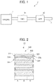
- FIG. 1 is a view illustrating a configuration of an exhaust gas purifier for an internal combustion engine, according to an embodiment of the present invention
- FIG. 2 is a schematic cross-sectional view of a gasoline particulate filter (GPF) according to the embodiment described above;
- GPF gasoline particulate filter
- FIG. 3 is an enlarged view of a pair of a cell on an inflow side and a cell on an outflow side in FIG. 2 ;
- FIG. 4 is a graph of a catalyst area ratio on the inflow side (an on-wall ratio) in the cell on the inflow side, in an example
- FIG. 5 is a graph of a catalyst area ratio on the outflow side (an on-wall ratio) in the cell on the outflow side, in the example;
- FIG. 6 is a graph of a measured median pore size (D50), among sizes of pores in partition walls after the exhaust gas purification catalyst is supported, in the example;
- FIG. 7 is a graph illustrating a relationship between a thickness of each of the partition walls and a ratio of collecting particulate matter, in the example
- FIG. 8 is a graph illustrating a relationship between the thickness of each of the partition walls and a pressure loss, in the example.
- FIG. 9 is a graph illustrating a relationship between a median pore size (D50), among sizes of pores in the partition walls and a pressure loss before the exhaust gas purification catalyst is supported, in the example;
- FIG. 10 is a graph illustrating a relationship between a size of an opening of one of the cells and a pressure loss, in the example.
- FIG. 11 is a view illustrating the efficiency of reducing HC when zeolite is disposed on the exhaust gas purification catalyst.
- FIG. 1 is a view illustrating a configuration of an exhaust gas purifier 2 for an internal combustion engine (hereinafter referred to as “engine”) 1 , according to the present embodiment.
- the engine 1 is a direct injection gasoline engine.
- the exhaust gas purifier 2 includes a three way catalyst (TWC) 31 and a gasoline particulate filter (GPF) 32 serving as an exhaust gas purification filter, which are provided in order from an upstream side of an exhaust pipe 3 through which exhaust gas passes.
- TWC three way catalyst
- GPF gasoline particulate filter
- the TWC 31 is configured to purify exhaust gas by oxidizing or reducing HC, CO, and NOx in the exhaust gas respectively into H 2 O and CO 2 , CO 2 , and N 2 .
- a carrier made of an oxide of alumina, silica, zirconia, titania, ceria, or zeolite is caused to support a noble metal such as Pd or Rh serving as a catalyst metal.
- the TWC 31 is typically supported by a honeycomb supporting body.
- the TWC 31 contains an oxygen storage capacity (OSC) material having an OSC.
- OSC oxygen storage capacity
- CeO 2 or a complex oxide of CeO 2 and ZrO 2 (hereinafter referred to as “CeZr complex oxide”) is used, for example.
- CeZr complex oxide is preferably used because it has high durability. Note that such a catalyst metal as described above may be supported by such an OSC material as described above.
- a method of preparing the TWC 31 is not particularly limited.
- the TWC 31 is prepared through a conventionally known slurry process, for example. For example, it is prepared, after slurry containing an oxide, a noble metal, and an OSC material, as described above, is prepared, by causing a honeycomb supporting body made of cordierite to be coated with the prepared slurry and to be fired.
- the GPF 32 is configured to collect and purify particulate matter in exhaust gas. Specifically, as exhaust gas passes through fine pores in partition walls described later, particulate matter is accumulated on the surfaces of the partition walls. The particulate matter is thus collected.
- particulate matter described in the present specification refers to particulate matter (PM) such as soot (carbon soot), oil cinders (soluble organic fraction or SOF), and oil ash (ash), for example.
- PM particulate matter
- emission regulations for such particulate matter have become stricter. That is, such regulations are aimed to regulate not only a total weight of such particulate matter to be discharged (g/km, g/kW) (PM regulations), but also the number of fine particulate matter to be discharged, which have a particle size of 2.5 ⁇ m or less, such as PM2.5, (PN regulations), for example.
- the GPF 32 according to the present embodiment is able to satisfy such PM regulations and PN regulations.
- FIG. 2 is a schematic cross-sectional view of the GPF 32 according to the present embodiment.
- FIG. 3 is an enlarged cross-sectional view of a pair of a cell on an inflow side and a cell on an outflow side in FIG. 2 .
- the GPF 32 includes a filter base material 320 and an exhaust gas purification catalyst supported by partition walls 323 of the filter base material 320 (a TWC 33 in the present embodiment).
- the filter base material 320 has a columnar shape extending longer in an axial direction, for example.
- the filter base material 320 is made from a porous body of cordierite, mullite, or silicon carbide (SiC), for example.
- the filter base material 320 is provided with a plurality of cells each extending from an inflow side end face 32 a to an outflow side end face 32 b .
- the cells are partitioned and formed by the partition walls 323 .
- the filter base material 320 includes inflow side seal parts 324 each sealing an opening at the inflow side end face 32 a . Some of the cells, where the openings at the inflow side end faces 32 a are sealed by the inflow side seal parts 324 , form outflow side cells 322 , where inflow side ends are closed, while outflow side ends are opened, causing exhaust gas passed through the partition walls 323 to flow toward downstream.
- the inflow side seal parts 324 are formed by sealing the inflow side end faces 32 a of the filter base material 320 with sealing cement.
- the filter base material 320 includes outflow side seal parts 325 each sealing an opening at the outflow side end face 32 b . Some of the cells, where the openings at the outflow side end faces 32 b are sealed by the outflow side seal parts 325 , form inflow side cells 321 , where inflow side ends are opened, while outflow side ends are closed, causing exhaust gas to enter from the exhaust pipe 3 .
- the outflow side seal parts 325 are formed by sealing the outflow side end faces 32 b of the filter base material 320 with sealing cement.
- the inflow side cells 321 where the openings at the outflow side end faces 32 b are sealed, and the outflow side cells 322 , where the openings at the inflow side end faces 32 a are sealed, are alternately disposed.
- exhaust gas which has entered the inflow side cells 321 , enters the partition walls 323 , passes through the partition walls 323 , and enters the outflow side cells 322 .
- a side to which exhaust gas enters the partition walls 323 refers to an inlet side (inlet).
- a side from which the exhaust gas exits the partition walls 323 refers to an outlet side (outlet).
- a three way catalyst i.e., the TWC 33
- the TWC 33 is supported by inner surfaces of the partition walls 323 forming the inflow side cells 321 and the outflow side cells 322 . It is possible to use, as a three way catalyst, a catalyst such as the TWC 31 described above.
- the TWC 33 is configured to purify, similar to the TWC 31 described above, exhaust gas by oxidizing or reducing HC, CO, and NOx in the exhaust gas respectively into H 2 O and CO 2 , CO 2 , and N 2 .
- the TWC 33 for example, one is used, in which a carrier made of an oxide of alumina, silica, zirconia, titania, ceria, or zeolite is caused to support a noble metal such as Pd or Rh serving as a catalyst metal. Among many noble metals, Pd and Rh are preferable as catalyst metals to be supported.
- the TWC 33 brings an effect of further collecting particulate matter.
- the TWC 33 may contain an oxygen storage capacity (OSC) material (an oxygen absorbing and desorbing material).
- OSC oxygen storage capacity
- CeO 2 or a complex oxide of CeO 2 and ZrO 2 (hereinafter referred to as “CeZr complex oxide”) is used, for example.
- CeZr complex oxide is preferably used because it has high durability.
- a catalyst metal as described above may be supported by such an OSC material as described above.
- it is preferable that a ratio between fuel and air (an air-fuel ratio) is kept closer to a stoichiometric ratio for complete combustion reactions.
- an OSC material having an oxygen absorbing and desorbing capability with which oxygen is absorbed under an oxidizing atmosphere, while oxygen is desorbed under a reducing atmosphere, it is possible to acquire a catalyst having a higher purification capability.
- a method of preparing the TWC 33 is not particularly limited.
- the TWC 33 is prepared through a conventionally known slurry process, for example. For example, it is prepared, after a slurry containing an oxide, a noble metal, and an OSC material, as described above, is prepared through milling, by causing the filter base material 320 to be coated with the prepared slurry and to be fired.
- a wash coating amount of the TWC 33 ranges from 60 g/L or 110 g/L inclusive. It is therefore possible to reduce an increase in pressure loss, and to acquire an effect of collecting particulate matter.
- the wash coating amount described in the present invention means an amount (g) of an exhaust gas purification catalyst supported by the partition walls 323 per a partition wall volume of 1 L. Note that the exhaust gas purification catalyst, i.e., the TWC 33 , is supported by not only the surfaces of the partition walls 323 (in an on-wall manner), but also inside the partition walls 323 (in an in-wall manner).
- the inflow side cells 321 and the outflow side cells 322 of the exhaust gas purification filter 320 are divided into three parts from the inflow side to the outflow side, such as an upstream part A, a middle part B, and a downstream part C, for purposes of convenience.
- a TWC 33 A, a TWC 33 B, and a TWC 33 C are respectively supported by inner wall surfaces of partition walls 323 A, 323 B, 323 C respectively forming the upstream part A, the middle part B, and the downstream part C.
- the upstream part, the middle part, and the downstream part described in the present invention respectively mean substantially three-divided parts in a longer direction of the cells from the inflow side to the outflow side.
- the GPF 32 is manufactured through a piston pushing-up method, for example.
- a piston pushing-up method a slurry containing constituent materials of an exhaust gas purification catalyst respectively at predetermined amounts is produced through milling.
- the produced slurry is caused to flow into slurry inflow inlets at the end faces on the inflow side of the filter base material 320 under predetermined conditions through the piston pushing-up method at a predetermined wash coating (WC) amount.
- WC wash coating
- the filter base material 320 is thus caused to support the exhaust gas purification catalyst. After drying and firing are performed, the GPF 32 is acquired.
- one cell on the inflow side and one cell on the outflow side, which lie adjacent to each other are regarded as a pair, and a catalyst area ratio is measured. That is, an average value (an upstream part average value) for one cell on the inflow side and one cell on the outflow side, which lie adjacent to each other, on the upstream part, an average value (a middle part average value) for one cell on the inflow side and one cell on the outflow side, which lie adjacent to each other, on the middle part, and an average value (a middle part average value) for one cell on the inflow side and one cell on the outflow side, which lie adjacent to each other, on the downstream part are respectively acquired.
- a minimum value, among the three average values is regarded as a “minimum value among average values” in the present invention.
- an inflow side catalyst area ratio Ain is acquired by measuring with a scanning electron microscope (SEM) an area ratio of the exhaust gas purification catalyst supported by the surfaces of the partition walls.
- SEM scanning electron microscope
- an inflow side catalyst area ratio Aout is acquired by measuring with the SEM an area ratio of the exhaust gas purification catalyst supported by the surfaces of the partition walls. An average value of the both is regarded as an upstream part average value Aave.
- an inflow side catalyst area ratio Bin and an inflow side catalyst area ratio Bout are acquired.
- An average value of the both is regarded as a middle part average value Bave.
- an inflow side catalyst area ratio Cin and an inflow side catalyst area ratio Cout are acquired.
- An average value of the both is regarded as a downstream part average value Cave.
- the upstream part average value Aave, the middle part average value Bave, and the downstream part average value Cave are compared with each other.
- a minimum value among the values, is regarded as a minimum value in the present invention.
- the downstream part average value Cave is regarded as a minimum value in the present invention.
- the minimum value is 28% or greater. Therefore, in all the upstream part A, the middle part B, and the downstream part C, area ratios of the exhaust gas purification catalyst supported by the surfaces of the partition walls are higher. It is thus possible to improve not only the capability of purifying NOx and other substances, but also the capability of collecting particulate matter.
- a minimum value of 30% or greater is preferable, of 40% or greater is more preferable, of 50%- or greater is particularly preferable, of 60% or greater is more particularly preferable, and of 64% or greater is most preferable.
- the upper limit is not particularly limited, but is 100%.
- a possible reason of why it is possible to improve the capability of collecting particulate matter by allowing an area ratio of the catalyst supported by the surfaces of the partition walls to fall within such a range as described above is that no larger holes allowing particulate matter to pass through are exposed on the surfaces of the base material.
- the upstream part average value Aave, the middle part average value Bave, and the downstream part average value Cave are all 43% or greater. Furthermore, for at least two or more of the values, 50% or greater is preferable, 60% or greater is more preferable, 70% or greater is particularly preferable, and 80% or greater is most preferable.
- predetermined locations for measuring area ratios for the cells on the inflow side and the cells on the outflow side represent locations each at an identical distance from respective opening parts of the upstream part A, the middle part B, and the downstream part C. (In the middle part B, there is no actual opening parts. However, it means virtual opening parts at cut sections.)
- an “inflow side catalyst area ratio” and an “outflow side catalyst area ratio” refer to area ratios that, when the surface of an exhaust gas purification catalyst is viewed, are measured by binarizing a scanning electron microscopy (SEM) image. Specifically, an ordinary scanning electron microscope (SEM, an electron microscope) is used. Images of two cells on the inflow side and two cells on the outflow side are acquired. Binarization is performed based on contrast differences between the base material and the catalyst in the acquired images. An area of the catalyst actually applied in an area supposed to be applied with catalyst on the plane of the base material, excluding the cut wall surface, is thus determined as an area ratio.
- SEM scanning electron microscopy
- the median pore sizes (D50), among sizes of the pores in A, B, and C, respectively, are measured at locations in the upstream part A, the middle part B, and the downstream part C, as described above.
- the median pore size (D50), among sizes of the pores, are (the partition walls 323 A+the TWC 33 A)>(the partition walls 323 B+the TWC 33 B)>(the partition walls 323 C+the TWC 33 C)
- the median pore size (D50), among the sizes of the pores in (the partition walls 323 A+the TWC 33 A), which indicates the maximum value is 14.6 ⁇ m or less.
- it is 14.0 ⁇ m or less. More preferably, it is 13.0 ⁇ m or less. Particularly preferably, it is 12.4 ⁇ m or less. It is preferable that a lower limit value is 7.5 ⁇ m or greater.
- a median pore size is measured with an Hg porosimeter.
- the median pore size represents a pore size when a volume ratio is 50% (D50).
- FIG. 4 is a graph of inflow side catalyst area ratios (on-wall ratios) measured in the cells on the inflow side, in Example 1 and a comparative example.
- FIG. 5 is a graph of outflow side catalyst area ratios (on-wall ratios) measured in the cells on the outflow side, in Example 1 and the comparative example (the illustration of Example 2 is omitted).
- a (top) represents the upstream part A.
- B (mid) represents the middle part B.
- C (bot) represents the downstream part C.
- FIG. 6 is a graph of a measured median pore size (D50), among sizes of pores in the partition walls after the exhaust gas purification catalyst is supported, in Example 1.
- D50 median pore size
- MPS on the vertical axis stands for a median pore size (D50).
- the exhaust gas purification catalysts according to the example and the comparative example are produced with the procedure described below.
- the minimum value among catalyst area ratios (on-wall ratios) described above and the maximum value among median pore sizes (D50) described later are as follows.
- nitric acid Pd and nitric acid Rh and an Al 2 O 3 carrier were loaded into an evaporator to allow Pd and Rh to be impregnated into and supported by the Al 2 O 3 carrier at a mass ratio of 6/1.
- firing was performed at a temperature of 600° C.
- a Pd—Rh/Al 2 O 3 catalyst was acquired.
- nitric acid Pd, nitric acid Rh, and CeO 2 were prepared.
- a Pd—Rh/CeO 2 catalyst was acquired.
- Pd was 1.51% by mass, while Rh was 0.25% by mass.
- the Pd—Rh/Al 2 O, catalyst and the Pd—Rh/CeO 2 catalyst were mixed at equal amounts, respectively. Water and a binder were further added and mixed. Milling was performed with a ball mill. A slurry was thus prepared. At a wash coating (WC) amount of 80 g/L, the filter base material was caused to support the TWC described above. After that, while air is allowed to flow, drying was performed at a temperature of 150° C. Firing was then performed at a temperature of 600° C. In the example and the comparative example, respectively, adjustments were performed to allow a catalyst area ratio (an on-wall ratio) and a median pore size to attain those values as described above. The exhaust gas purification filters according to the example and the comparative example were thus acquired.
- WC wash coating
- the GPFs to be tested were respectively installed in vehicles, each at a location behind a 0.6-L three way catalyst located immediately behind a gasoline direct injection engine having a displacement of 1.5 L.
- the vehicles were driven under the conditions of a room temperature of 25° C. and a humidity of 50%.
- the numbers of PMs (PNs) were measured at locations in front of and behind the GPFs at that time. Efficiency of collecting the numbers of PMs (PNs) (reduction ratios) was calculated.
- the vehicles were driven for one cycle conforming to the worldwide harmonized light vehicles text procedure (WLTP) as preprocessing. Particulate matter remaining in the GPFs was removed. Soaking was performed for 24 hours at a room temperature of 25° C. Measurements were performed from a cold state to acquire data.
- WLTP worldwide harmonized light vehicles text procedure
- FIG. 7 is a graph illustrating a relationship between a thickness of each of the partition walls and a ratio of collecting particulate matter, in Example 1.
- FIG. 8 is a graph illustrating a relationship between the thickness of each of the partition walls and a pressure loss, in Example 1. The value of a pressure loss is acquired through the test method as described below. An amount of accumulated ash was 96 g. A measured flow rate was 25 m 3 /min.
- each of the partition walls ranges from 9 mil to 11 mil inclusive (0.2286 mm to 0.2794 mm inclusive). It is thus possible to understand that there are improvements in both the ratio of collecting particulate matter and pressure loss.
- FIG. 9 is a graph illustrating a measured relationship between a median pore size (D50), among sizes of pores in the partition walls, and a pressure loss before the exhaust gas purification catalyst is supported, in Example 1.
- An amount of accumulated ash was 150 g.
- a measured flow rate was 12 m 3 /min.
- the median pore size ranges from 12 ⁇ m to 18 ⁇ m inclusive. It is thus possible to understand that there are improvements in pressure loss.
- FIG. 10 is a graph illustrating a relationship between the size of the opening of one of the cells and a pressure loss in Example 1.
- HAC D 1 >D 2 in FIG. 3
- FIG. 11 is a view illustrating the efficiency of reducing HC when zeolite is disposed on the exhaust gas purification catalyst according to Example 1. As illustrated in FIG. 11 , when zeolite is disposed on the exhaust gas purification catalyst, a ratio of absorbing HC exceeds a ratio of desorbing HC. It is thus possible to understand that there are improvements in the efficiency of reducing HC by a difference of 3.0%.
- the exhaust gas purification filter according to the present invention has been applied to the GPF.
- the exhaust gas purification filter according to the present invention may be applied to a diesel particulate filter (DPF).
- DPF diesel particulate filter
- an exhaust gas purification catalyst is not limited to a TWC.
- Another exhaust gas purification catalyst may be used.
- an oxidation catalyst such as a PM combustion catalyst.
Landscapes
- Chemical & Material Sciences (AREA)
- Engineering & Computer Science (AREA)
- Chemical Kinetics & Catalysis (AREA)
- Combustion & Propulsion (AREA)
- General Engineering & Computer Science (AREA)
- Mechanical Engineering (AREA)
- Health & Medical Sciences (AREA)
- Physics & Mathematics (AREA)
- Geometry (AREA)
- Materials Engineering (AREA)
- Organic Chemistry (AREA)
- General Chemical & Material Sciences (AREA)
- Oil, Petroleum & Natural Gas (AREA)
- Biomedical Technology (AREA)
- Analytical Chemistry (AREA)
- Environmental & Geological Engineering (AREA)
- Ceramic Engineering (AREA)
- Toxicology (AREA)
- Crystallography & Structural Chemistry (AREA)
- Catalysts (AREA)
- Exhaust Gas Treatment By Means Of Catalyst (AREA)
- Processes For Solid Components From Exhaust (AREA)
Applications Claiming Priority (3)
| Application Number | Priority Date | Filing Date | Title |
|---|---|---|---|
| JP2021-006008 | 2021-01-18 | ||
| JP2021006008A JP7178432B2 (ja) | 2021-01-18 | 2021-01-18 | 排気浄化フィルタ |
| JPJP2021-006008 | 2021-01-18 |
Publications (2)
| Publication Number | Publication Date |
|---|---|
| US20220226760A1 US20220226760A1 (en) | 2022-07-21 |
| US11529578B2 true US11529578B2 (en) | 2022-12-20 |
Family
ID=82405951
Family Applications (1)
| Application Number | Title | Priority Date | Filing Date |
|---|---|---|---|
| US17/647,732 Active US11529578B2 (en) | 2021-01-18 | 2022-01-11 | Exhaust gas purification filter |
Country Status (3)
| Country | Link |
|---|---|
| US (1) | US11529578B2 (ja) |
| JP (1) | JP7178432B2 (ja) |
| CN (1) | CN114810283B (ja) |
Citations (12)
| Publication number | Priority date | Publication date | Assignee | Title |
|---|---|---|---|---|
| US20020178707A1 (en) * | 2001-04-23 | 2002-12-05 | Vance Fredrick W. | Method of making wall-flow monolith filter |
| US20030176280A1 (en) * | 2002-02-28 | 2003-09-18 | Philippe Caze | Structured catalysts incorporating thick washcoats and method |
| US20070119135A1 (en) * | 2005-11-30 | 2007-05-31 | Weiguo Miao | Controlled pore size distribution porous ceramic honeycomb filter, honeycomb green body, batch mixture and manufacturing method therefor |
| US20090274867A1 (en) * | 2006-12-27 | 2009-11-05 | Ngk Insulators, Ltd. | Honeycomb structure and method for manufacturing the same |
| US20100234206A1 (en) * | 2006-11-30 | 2010-09-16 | Weiguo Miao | Controlled Pore Size Distribution Porous Ceramic Honeycomb Filter, Honeycomb Green Body, Batch Mixture And Manufacturing Method Therefor |
| US7981375B2 (en) * | 2007-08-03 | 2011-07-19 | Errcive, Inc. | Porous bodies and methods |
| US20110212007A1 (en) * | 2010-02-26 | 2011-09-01 | Yanxia Ann Lu | Low pressure drop extruded catalyst filter |
| US20140061981A1 (en) * | 2012-09-04 | 2014-03-06 | Kubota Corporation | Ceramic filter and methods for manufacturing and using same |
| US20140134063A1 (en) * | 2011-07-13 | 2014-05-15 | Haldor Topsøe A/S | Method for coating a catalysed particulate filter and a particulate filter |
| WO2017056067A1 (en) | 2015-09-30 | 2017-04-06 | Johnson Matthey Public Limited Company | Gasoline particulate filter |
| US20170274366A1 (en) * | 2016-03-28 | 2017-09-28 | Ngk Insulators, Ltd. | Honeycomb structure |
| US20190203621A1 (en) * | 2017-12-28 | 2019-07-04 | Honda Motor Co.,Ltd. | Exhaust purifying filter |
Family Cites Families (6)
| Publication number | Priority date | Publication date | Assignee | Title |
|---|---|---|---|---|
| JP5649945B2 (ja) | 2009-12-25 | 2015-01-07 | 日本碍子株式会社 | 表面捕集層付き担体及び触媒担持表面捕集層付き担体 |
| JP6564637B2 (ja) * | 2014-10-09 | 2019-08-21 | 株式会社キャタラー | 排ガス浄化装置 |
| JP6538246B2 (ja) | 2018-07-02 | 2019-07-03 | 本田技研工業株式会社 | 内燃機関の排気浄化システム |
| WO2020039650A1 (ja) * | 2018-08-22 | 2020-02-27 | 三井金属鉱業株式会社 | 排ガス浄化用触媒 |
| JP7013361B2 (ja) | 2018-11-15 | 2022-02-15 | 株式会社キャタラー | パティキュレートフィルタ |
| JP6570785B1 (ja) | 2019-06-04 | 2019-09-04 | 本田技研工業株式会社 | 内燃機関の排気浄化システム |
-
2021
- 2021-01-18 JP JP2021006008A patent/JP7178432B2/ja active Active
-
2022
- 2022-01-11 US US17/647,732 patent/US11529578B2/en active Active
- 2022-01-18 CN CN202210053850.2A patent/CN114810283B/zh active Active
Patent Citations (13)
| Publication number | Priority date | Publication date | Assignee | Title |
|---|---|---|---|---|
| US20020178707A1 (en) * | 2001-04-23 | 2002-12-05 | Vance Fredrick W. | Method of making wall-flow monolith filter |
| US20030176280A1 (en) * | 2002-02-28 | 2003-09-18 | Philippe Caze | Structured catalysts incorporating thick washcoats and method |
| US20070119135A1 (en) * | 2005-11-30 | 2007-05-31 | Weiguo Miao | Controlled pore size distribution porous ceramic honeycomb filter, honeycomb green body, batch mixture and manufacturing method therefor |
| US20100234206A1 (en) * | 2006-11-30 | 2010-09-16 | Weiguo Miao | Controlled Pore Size Distribution Porous Ceramic Honeycomb Filter, Honeycomb Green Body, Batch Mixture And Manufacturing Method Therefor |
| US20090274867A1 (en) * | 2006-12-27 | 2009-11-05 | Ngk Insulators, Ltd. | Honeycomb structure and method for manufacturing the same |
| US7981375B2 (en) * | 2007-08-03 | 2011-07-19 | Errcive, Inc. | Porous bodies and methods |
| US20110212007A1 (en) * | 2010-02-26 | 2011-09-01 | Yanxia Ann Lu | Low pressure drop extruded catalyst filter |
| US20140134063A1 (en) * | 2011-07-13 | 2014-05-15 | Haldor Topsøe A/S | Method for coating a catalysed particulate filter and a particulate filter |
| US20140061981A1 (en) * | 2012-09-04 | 2014-03-06 | Kubota Corporation | Ceramic filter and methods for manufacturing and using same |
| WO2017056067A1 (en) | 2015-09-30 | 2017-04-06 | Johnson Matthey Public Limited Company | Gasoline particulate filter |
| JP2018537265A (ja) | 2015-09-30 | 2018-12-20 | ジョンソン、マッセイ、パブリック、リミテッド、カンパニーJohnson Matthey Public Limited Company | ガソリン・パティキュレート・フィルタ |
| US20170274366A1 (en) * | 2016-03-28 | 2017-09-28 | Ngk Insulators, Ltd. | Honeycomb structure |
| US20190203621A1 (en) * | 2017-12-28 | 2019-07-04 | Honda Motor Co.,Ltd. | Exhaust purifying filter |
Also Published As
| Publication number | Publication date |
|---|---|
| JP7178432B2 (ja) | 2022-11-25 |
| CN114810283B (zh) | 2024-04-02 |
| JP2022110535A (ja) | 2022-07-29 |
| US20220226760A1 (en) | 2022-07-21 |
| CN114810283A (zh) | 2022-07-29 |
Similar Documents
| Publication | Publication Date | Title |
|---|---|---|
| CN107249738B (zh) | 排气净化用催化剂 | |
| JP6564637B2 (ja) | 排ガス浄化装置 | |
| CN109973176B (zh) | 排气净化过滤器 | |
| US11208931B2 (en) | Exhaust gas purification catalyst | |
| US11097260B2 (en) | Exhaust gas purification device | |
| KR20150140727A (ko) | 삼원 촉매를 포함하는 필터 기재 | |
| US11266982B2 (en) | Exhaust gas purification catalyst | |
| WO2016056573A1 (ja) | 排ガス浄化装置 | |
| WO2020203198A1 (ja) | 排気浄化フィルタ | |
| US11529578B2 (en) | Exhaust gas purification filter | |
| US20220054978A1 (en) | Exhaust gas purification filter | |
| US11473472B2 (en) | Exhaust gas control apparatus and manufacturing method thereof | |
| US20240100478A1 (en) | Catalytically active particle filter with a high degree of filtering efficiency | |
| CN112218718B (zh) | 废气净化催化剂 | |
| JP2020193568A (ja) | 排ガス浄化装置 | |
| JPWO2018180593A1 (ja) | 排ガス浄化用触媒 | |
| US20220226763A1 (en) | Exhaust emission control filter | |
| WO2022163720A1 (ja) | ガソリンエンジン用排ガス浄化触媒フィルター | |
| CN112203764B (zh) | 废气净化催化剂的制造方法 | |
| JP2022156448A (ja) | ガソリンエンジン用排ガス浄化用触媒、及びこれを用いた排ガス浄化システム | |
| JP2022066003A (ja) | 触媒化ガソリン微粒子フィルターおよびこれを利用した微粒子成分を含む排ガスを浄化する方法 |
Legal Events
| Date | Code | Title | Description |
|---|---|---|---|
| FEPP | Fee payment procedure |
Free format text: ENTITY STATUS SET TO UNDISCOUNTED (ORIGINAL EVENT CODE: BIG.); ENTITY STATUS OF PATENT OWNER: LARGE ENTITY |
|
| AS | Assignment |
Owner name: HONDA MOTOR CO., LTD., JAPAN Free format text: ASSIGNMENT OF ASSIGNORS INTEREST;ASSIGNORS:MORI, TAKESHI;TSUYAMA, TOMOKO;WATANABE, TAKAYUKI;REEL/FRAME:058638/0096 Effective date: 20220112 |
|
| STPP | Information on status: patent application and granting procedure in general |
Free format text: DOCKETED NEW CASE - READY FOR EXAMINATION |
|
| STPP | Information on status: patent application and granting procedure in general |
Free format text: NOTICE OF ALLOWANCE MAILED -- APPLICATION RECEIVED IN OFFICE OF PUBLICATIONS |
|
| STPP | Information on status: patent application and granting procedure in general |
Free format text: PUBLICATIONS -- ISSUE FEE PAYMENT VERIFIED |
|
| STCF | Information on status: patent grant |
Free format text: PATENTED CASE |