US11525567B2 - Ventilation housing - Google Patents
Ventilation housing Download PDFInfo
- Publication number
- US11525567B2 US11525567B2 US17/283,894 US201917283894A US11525567B2 US 11525567 B2 US11525567 B2 US 11525567B2 US 201917283894 A US201917283894 A US 201917283894A US 11525567 B2 US11525567 B2 US 11525567B2
- Authority
- US
- United States
- Prior art keywords
- internal member
- ventilation
- ventilation assembly
- projection
- external member
- Prior art date
- Legal status (The legal status is an assumption and is not a legal conclusion. Google has not performed a legal analysis and makes no representation as to the accuracy of the status listed.)
- Active
Links
- 238000009423 ventilation Methods 0.000 title claims abstract description 305
- 230000002093 peripheral effect Effects 0.000 claims abstract description 107
- 239000012528 membrane Substances 0.000 claims abstract description 85
- 238000005304 joining Methods 0.000 claims description 8
- 230000007246 mechanism Effects 0.000 claims description 6
- 230000000052 comparative effect Effects 0.000 description 39
- 229920005989 resin Polymers 0.000 description 20
- 239000011347 resin Substances 0.000 description 20
- 238000003780 insertion Methods 0.000 description 19
- 230000037431 insertion Effects 0.000 description 19
- 230000000712 assembly Effects 0.000 description 16
- 238000000429 assembly Methods 0.000 description 16
- 239000000463 material Substances 0.000 description 15
- -1 polybutylene terephthalate Polymers 0.000 description 13
- 238000000034 method Methods 0.000 description 12
- XLYOFNOQVPJJNP-UHFFFAOYSA-N water Substances O XLYOFNOQVPJJNP-UHFFFAOYSA-N 0.000 description 12
- 239000004743 Polypropylene Substances 0.000 description 10
- 229920001155 polypropylene Polymers 0.000 description 10
- 238000007586 pull-out test Methods 0.000 description 9
- 239000005871 repellent Substances 0.000 description 9
- 238000009864 tensile test Methods 0.000 description 8
- 210000000078 claw Anatomy 0.000 description 7
- 229920001971 elastomer Polymers 0.000 description 7
- 238000001746 injection moulding Methods 0.000 description 7
- 238000003466 welding Methods 0.000 description 6
- 239000011248 coating agent Substances 0.000 description 5
- 238000000576 coating method Methods 0.000 description 5
- 239000000428 dust Substances 0.000 description 5
- 229920001343 polytetrafluoroethylene Polymers 0.000 description 5
- 239000004810 polytetrafluoroethylene Substances 0.000 description 5
- 239000000126 substance Substances 0.000 description 5
- 229920005992 thermoplastic resin Polymers 0.000 description 5
- 239000003795 chemical substances by application Substances 0.000 description 4
- 239000000806 elastomer Substances 0.000 description 4
- 230000003014 reinforcing effect Effects 0.000 description 4
- 229920002725 thermoplastic elastomer Polymers 0.000 description 4
- YCKRFDGAMUMZLT-UHFFFAOYSA-N Fluorine atom Chemical compound [F] YCKRFDGAMUMZLT-UHFFFAOYSA-N 0.000 description 3
- 239000004952 Polyamide Substances 0.000 description 3
- 150000001336 alkenes Chemical class 0.000 description 3
- 230000000694 effects Effects 0.000 description 3
- 229910052731 fluorine Inorganic materials 0.000 description 3
- 239000011737 fluorine Substances 0.000 description 3
- 238000005259 measurement Methods 0.000 description 3
- 229910052751 metal Inorganic materials 0.000 description 3
- 239000002184 metal Substances 0.000 description 3
- 238000000465 moulding Methods 0.000 description 3
- 239000004745 nonwoven fabric Substances 0.000 description 3
- 239000003921 oil Substances 0.000 description 3
- JRZJOMJEPLMPRA-UHFFFAOYSA-N olefin Natural products CCCCCCCC=C JRZJOMJEPLMPRA-UHFFFAOYSA-N 0.000 description 3
- 230000035699 permeability Effects 0.000 description 3
- 229920002647 polyamide Polymers 0.000 description 3
- 229920001707 polybutylene terephthalate Polymers 0.000 description 3
- 229920000139 polyethylene terephthalate Polymers 0.000 description 3
- 239000005020 polyethylene terephthalate Substances 0.000 description 3
- 229920000098 polyolefin Polymers 0.000 description 3
- VXNZUUAINFGPBY-UHFFFAOYSA-N 1-Butene Chemical compound CCC=C VXNZUUAINFGPBY-UHFFFAOYSA-N 0.000 description 2
- 229920000459 Nitrile rubber Polymers 0.000 description 2
- 239000004677 Nylon Substances 0.000 description 2
- 239000004734 Polyphenylene sulfide Substances 0.000 description 2
- XECAHXYUAAWDEL-UHFFFAOYSA-N acrylonitrile butadiene styrene Chemical compound C=CC=C.C=CC#N.C=CC1=CC=CC=C1 XECAHXYUAAWDEL-UHFFFAOYSA-N 0.000 description 2
- 229920000122 acrylonitrile butadiene styrene Polymers 0.000 description 2
- 239000004676 acrylonitrile butadiene styrene Substances 0.000 description 2
- 239000000853 adhesive Substances 0.000 description 2
- 230000001070 adhesive effect Effects 0.000 description 2
- 230000004323 axial length Effects 0.000 description 2
- 239000002131 composite material Substances 0.000 description 2
- 230000006835 compression Effects 0.000 description 2
- 238000007906 compression Methods 0.000 description 2
- 229920001577 copolymer Polymers 0.000 description 2
- 230000003247 decreasing effect Effects 0.000 description 2
- 238000006073 displacement reaction Methods 0.000 description 2
- 239000000178 monomer Substances 0.000 description 2
- 229920001778 nylon Polymers 0.000 description 2
- 239000012466 permeate Substances 0.000 description 2
- 239000004417 polycarbonate Substances 0.000 description 2
- 229920000515 polycarbonate Polymers 0.000 description 2
- 229920001955 polyphenylene ether Polymers 0.000 description 2
- 229920000069 polyphenylene sulfide Polymers 0.000 description 2
- 230000009467 reduction Effects 0.000 description 2
- 150000003839 salts Chemical class 0.000 description 2
- 239000002759 woven fabric Substances 0.000 description 2
- NPHULPIAPWNOOH-UHFFFAOYSA-N 2-[4-[2-(2,3-dihydro-1H-inden-2-ylamino)pyrimidin-5-yl]-3-(2,3-dihydroindol-1-ylmethyl)pyrazol-1-yl]-1-(2,4,6,7-tetrahydrotriazolo[4,5-c]pyridin-5-yl)ethanone Chemical compound C1C(CC2=CC=CC=C12)NC1=NC=C(C=N1)C=1C(=NN(C=1)CC(=O)N1CC2=C(CC1)NN=N2)CN1CCC2=CC=CC=C12 NPHULPIAPWNOOH-UHFFFAOYSA-N 0.000 description 1
- IKOKHHBZFDFMJW-UHFFFAOYSA-N 2-[4-[2-(2,3-dihydro-1H-inden-2-ylamino)pyrimidin-5-yl]-3-(2-morpholin-4-ylethoxy)pyrazol-1-yl]-1-(2,4,6,7-tetrahydrotriazolo[4,5-c]pyridin-5-yl)ethanone Chemical compound C1C(CC2=CC=CC=C12)NC1=NC=C(C=N1)C=1C(=NN(C=1)CC(=O)N1CC2=C(CC1)NN=N2)OCCN1CCOCC1 IKOKHHBZFDFMJW-UHFFFAOYSA-N 0.000 description 1
- 238000003855 Adhesive Lamination Methods 0.000 description 1
- 229920002943 EPDM rubber Polymers 0.000 description 1
- 229920000181 Ethylene propylene rubber Polymers 0.000 description 1
- 239000004698 Polyethylene Substances 0.000 description 1
- 239000004820 Pressure-sensitive adhesive Substances 0.000 description 1
- GWEVSGVZZGPLCZ-UHFFFAOYSA-N Titan oxide Chemical compound O=[Ti]=O GWEVSGVZZGPLCZ-UHFFFAOYSA-N 0.000 description 1
- FHKPLLOSJHHKNU-INIZCTEOSA-N [(3S)-3-[8-(1-ethyl-5-methylpyrazol-4-yl)-9-methylpurin-6-yl]oxypyrrolidin-1-yl]-(oxan-4-yl)methanone Chemical compound C(C)N1N=CC(=C1C)C=1N(C2=NC=NC(=C2N=1)O[C@@H]1CN(CC1)C(=O)C1CCOCC1)C FHKPLLOSJHHKNU-INIZCTEOSA-N 0.000 description 1
- JAWMENYCRQKKJY-UHFFFAOYSA-N [3-(2,4,6,7-tetrahydrotriazolo[4,5-c]pyridin-5-ylmethyl)-1-oxa-2,8-diazaspiro[4.5]dec-2-en-8-yl]-[2-[[3-(trifluoromethoxy)phenyl]methylamino]pyrimidin-5-yl]methanone Chemical compound N1N=NC=2CN(CCC=21)CC1=NOC2(C1)CCN(CC2)C(=O)C=1C=NC(=NC=1)NCC1=CC(=CC=C1)OC(F)(F)F JAWMENYCRQKKJY-UHFFFAOYSA-N 0.000 description 1
- 229920000800 acrylic rubber Polymers 0.000 description 1
- 239000000654 additive Substances 0.000 description 1
- 230000000996 additive effect Effects 0.000 description 1
- 239000006229 carbon black Substances 0.000 description 1
- 229920006026 co-polymeric resin Polymers 0.000 description 1
- 238000000748 compression moulding Methods 0.000 description 1
- 238000003618 dip coating Methods 0.000 description 1
- 238000001035 drying Methods 0.000 description 1
- 238000004070 electrodeposition Methods 0.000 description 1
- 238000007590 electrostatic spraying Methods 0.000 description 1
- 229920000840 ethylene tetrafluoroethylene copolymer Polymers 0.000 description 1
- 230000001747 exhibiting effect Effects 0.000 description 1
- 238000000605 extraction Methods 0.000 description 1
- 239000000835 fiber Substances 0.000 description 1
- 239000006260 foam Substances 0.000 description 1
- 239000011521 glass Substances 0.000 description 1
- 239000003365 glass fiber Substances 0.000 description 1
- 238000010438 heat treatment Methods 0.000 description 1
- 229920001519 homopolymer Polymers 0.000 description 1
- 238000005470 impregnation Methods 0.000 description 1
- 239000007788 liquid Substances 0.000 description 1
- 238000004519 manufacturing process Methods 0.000 description 1
- 239000002121 nanofiber Substances 0.000 description 1
- 239000002245 particle Substances 0.000 description 1
- 125000005010 perfluoroalkyl group Chemical group 0.000 description 1
- 239000000049 pigment Substances 0.000 description 1
- 229920000747 poly(lactic acid) Polymers 0.000 description 1
- 229920000058 polyacrylate Polymers 0.000 description 1
- 229920002239 polyacrylonitrile Polymers 0.000 description 1
- 239000004626 polylactic acid Substances 0.000 description 1
- 229920000642 polymer Polymers 0.000 description 1
- 238000006116 polymerization reaction Methods 0.000 description 1
- 239000011148 porous material Substances 0.000 description 1
- 239000000843 powder Substances 0.000 description 1
- 238000002360 preparation method Methods 0.000 description 1
- 238000003825 pressing Methods 0.000 description 1
- 239000012763 reinforcing filler Substances 0.000 description 1
- 238000007789 sealing Methods 0.000 description 1
- 229920002379 silicone rubber Polymers 0.000 description 1
- 239000004945 silicone rubber Substances 0.000 description 1
- 239000000243 solution Substances 0.000 description 1
- 238000004528 spin coating Methods 0.000 description 1
- 238000005507 spraying Methods 0.000 description 1
- 238000003892 spreading Methods 0.000 description 1
- 230000007480 spreading Effects 0.000 description 1
- 238000009823 thermal lamination Methods 0.000 description 1
- 229920001187 thermosetting polymer Polymers 0.000 description 1
- 235000010215 titanium dioxide Nutrition 0.000 description 1
Images


Classifications
-
- H—ELECTRICITY
- H05—ELECTRIC TECHNIQUES NOT OTHERWISE PROVIDED FOR
- H05K—PRINTED CIRCUITS; CASINGS OR CONSTRUCTIONAL DETAILS OF ELECTRIC APPARATUS; MANUFACTURE OF ASSEMBLAGES OF ELECTRICAL COMPONENTS
- H05K5/00—Casings, cabinets or drawers for electric apparatus
- H05K5/02—Details
- H05K5/0213—Venting apertures; Constructional details thereof
- H05K5/0216—Venting plugs comprising semi-permeable membranes
-
- B—PERFORMING OPERATIONS; TRANSPORTING
- B29—WORKING OF PLASTICS; WORKING OF SUBSTANCES IN A PLASTIC STATE IN GENERAL
- B29C—SHAPING OR JOINING OF PLASTICS; SHAPING OF MATERIAL IN A PLASTIC STATE, NOT OTHERWISE PROVIDED FOR; AFTER-TREATMENT OF THE SHAPED PRODUCTS, e.g. REPAIRING
- B29C33/00—Moulds or cores; Details thereof or accessories therefor
- B29C33/0033—Moulds or cores; Details thereof or accessories therefor constructed for making articles provided with holes
-
- F—MECHANICAL ENGINEERING; LIGHTING; HEATING; WEAPONS; BLASTING
- F21—LIGHTING
- F21S—NON-PORTABLE LIGHTING DEVICES; SYSTEMS THEREOF; VEHICLE LIGHTING DEVICES SPECIALLY ADAPTED FOR VEHICLE EXTERIORS
- F21S45/00—Arrangements within vehicle lighting devices specially adapted for vehicle exteriors, for purposes other than emission or distribution of light
- F21S45/30—Ventilation or drainage of lighting devices
-
- F—MECHANICAL ENGINEERING; LIGHTING; HEATING; WEAPONS; BLASTING
- F21—LIGHTING
- F21V—FUNCTIONAL FEATURES OR DETAILS OF LIGHTING DEVICES OR SYSTEMS THEREOF; STRUCTURAL COMBINATIONS OF LIGHTING DEVICES WITH OTHER ARTICLES, NOT OTHERWISE PROVIDED FOR
- F21V31/00—Gas-tight or water-tight arrangements
- F21V31/03—Gas-tight or water-tight arrangements with provision for venting
-
- H—ELECTRICITY
- H05—ELECTRIC TECHNIQUES NOT OTHERWISE PROVIDED FOR
- H05K—PRINTED CIRCUITS; CASINGS OR CONSTRUCTIONAL DETAILS OF ELECTRIC APPARATUS; MANUFACTURE OF ASSEMBLAGES OF ELECTRICAL COMPONENTS
- H05K5/00—Casings, cabinets or drawers for electric apparatus
- H05K5/02—Details
- H05K5/0213—Venting apertures; Constructional details thereof
- H05K5/0215—Venting apertures; Constructional details thereof with semi-permeable membranes attached to casings
-
- H—ELECTRICITY
- H05—ELECTRIC TECHNIQUES NOT OTHERWISE PROVIDED FOR
- H05K—PRINTED CIRCUITS; CASINGS OR CONSTRUCTIONAL DETAILS OF ELECTRIC APPARATUS; MANUFACTURE OF ASSEMBLAGES OF ELECTRICAL COMPONENTS
- H05K5/00—Casings, cabinets or drawers for electric apparatus
- H05K5/06—Hermetically-sealed casings
- H05K5/068—Hermetically-sealed casings having a pressure compensation device, e.g. membrane
Definitions
- the present invention relates to a ventilation housing including a ventilation assembly fixed.
- Ventilation assemblies for ensuring ventilation between the inside and the outside of a housing, reducing pressure variation inside the housing, and so on are sometimes fixed to housings of in-vehicle electrical components such as lamps, inverters, converters, electronic control units (ECUs), battery packs, radars, and cameras and various electronic devices for home use, medical use, office use, etc. Ventilation assemblies are required to have, in addition to ventilation properties, various properties such as dust proofness for preventing entry of dust into housings, water proofness for preventing entry of water into housings, oil proofness for preventing entry of oil into housings, and CCT resistance for preventing entry of salt into housings depending on the specific electrical components, etc. to which the ventilation assemblies are fixed.
- Patent Literature 1 discloses a ventilation assembly that can satisfy the ventilation properties and the various required properties.
- FIG. 28 shows the ventilation assembly disclosed in Patent Literature 1.
- a ventilation assembly 101 shown in FIG. 28 includes an internal member 102 which is a tubular body having openings at both end portions 108 and 109 , a gas-permeable membrane 103 covering the opening at the one end portion 108 of the internal member 102 , and an external member 104 which is a tubular body having a bottom.
- the external member 104 is joined to the internal member 102 with the internal member 102 inserted in the interior of the external member 104 from the end portion 108 side.
- the external member 104 includes a projecting portion 106 projecting from an inner side 105 of a bottom portion in the direction along the central axis of the ventilation assembly 101 .
- the projecting portion 106 abuts the gas-permeable membrane 103 disposed at the end portion 108 of the internal member 102 . Since the projecting portion 106 abuts the gas-permeable membrane 103 , the external member 104 and the gas-permeable membrane 103 are kept spaced apart from each other. Between the inner side 105 of the bottom portion of the external member 104 and the gas-permeable membrane 103 and between the outer peripheral surface of the internal member 102 and the inner peripheral surface of the external member 104 , the ventilation assembly 101 has a space 107 serving as a ventilation path 115 connecting the exterior of the ventilation assembly 101 and the gas-permeable membrane 103 .
- the ventilation assembly 101 is fixed to a tubular projection 112 extending to project from the outer surface of a housing 111 and internally having a space 110 communicating the inside and the outside of the housing 111 .
- the projection 112 is inserted in the internal member 102 through the opening at the other end portion 109 of the internal member 102 to fix the ventilation assembly 101 to the projection 112 . This allows ventilation between the inside and the outside of the housing 111 through the projection 112 and the ventilation assembly 101 with the ventilation assembly 101 fixed.
- Patent Literature 1 JP 2003-336874 A
- the present invention aims to provide a ventilation housing including a housing and a ventilation assembly, exhibiting excellent performance in terms of moisture permeation between the inside and the outside of the housing, and being capable of reducing dropping of the ventilation assembly from the projection of the housing.
- the present invention provides a ventilation housing including:
- the housing includes a tubular projection extending to project from an outer surface of the housing and internally having a first space communicating the inside and the outside of the housing,
- the ventilation assembly includes:
- the ventilation assembly is fixed to the projection with the projection inserted in the opening at the second end portion of the internal member to make an inner peripheral surface of the internal member and an outer peripheral surface of the projection abut each other,
- the ventilation assembly has a second space serving as a ventilation path connecting the gas-permeable membrane and the outside of the ventilation assembly in at least one selected from the inside of the internal member, the inside of the external member, and an interspace between the internal member and the external member joined together,
- a height H 1 of the internal member is 6.0 mm or more and 10 mm or less
- a ratio H 1 /H 2 of the height H 1 of the internal member to a height H 2 of the projection is 1.00 or more and 1.70 or less.
- the ventilation housing in which the height of the internal member and the ratio of the height of the internal member to the height of the projection are controlled as described above exhibits excellent moisture permeation performance.
- a conventional ventilation assembly easily drops from a projection of a housing; on the other hand, the ventilation housing controlled as described above can reduce dropping from the projection of the housing.
- FIG. 1 A is a cross-sectional view schematically showing a ventilation assembly of a first embodiment.
- FIG. 1 B is a cross-sectional view schematically showing the ventilation assembly of the first embodiment.
- FIG. 2 is an exploded perspective view schematically showing the ventilation assembly of the first embodiment.
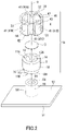
- FIG. 3 A is a cross-sectional view schematically showing a ventilation assembly of a second embodiment.
- FIG. 3 B is a cross-sectional view schematically showing the ventilation assembly of the second embodiment.
- FIG. 4 is an exploded perspective view schematically showing the ventilation assembly of the second embodiment.
- FIG. 5 A is a cross-sectional view schematically showing a ventilation assembly of a third embodiment.
- FIG. 5 B is a cross-sectional view schematically showing the ventilation assembly of the third embodiment.
- FIG. 6 is an exploded perspective view schematically showing the ventilation assembly of the third embodiment.
- FIG. 7 A is a cross-sectional view schematically showing a ventilation assembly of a fourth embodiment.
- FIG. 7 B is a cross-sectional view schematically showing the ventilation assembly of the fourth embodiment.
- FIG. 8 is an exploded perspective view schematically showing the ventilation assembly of the fourth embodiment.
- FIG. 9 A is a cross-sectional view schematically showing a ventilation assembly of a fifth embodiment.
- FIG. 9 B is a cross-sectional view schematically showing the ventilation assembly of the fifth embodiment.
- FIG. 10 is an exploded perspective view schematically showing the ventilation assembly of the fifth embodiment.
- FIG. 11 A is a perspective view of a ventilation assembly produced in EXAMPLES.
- FIG. 11 B is a perspective view schematically showing an external member included in the ventilation assembly of FIG. 11 A .
- FIG. 12 A is a plan view schematically showing a housing lid used to evaluate the moisture permeation performance (moisture permeation rate) of a ventilation housing.
- FIG. 12 B is a schematic view showing a cross-section of the housing lid of FIG. 12 A .
- FIG. 13 A is a perspective view of a ventilation assembly produced in EXAMPLES.
- FIG. 13 B is a perspective view schematically showing an external member included in the ventilation assembly of FIG. 13 A .
- FIG. 14 is a graph on which a relation between moisture permeation rates and ventilation distances is plotted for Examples 1 to 4 and Comparative Examples 1 to 9.
- FIG. 15 A is a perspective view of a ventilation assembly produced in EXAMPLES.
- FIG. 15 B is a perspective view schematically showing an external member included in the ventilation assembly of FIG. 15 A .
- FIG. 16 A is a perspective view of a ventilation assembly produced in EXAMPLES.
- FIG. 16 B is a perspective view schematically showing an external member included in the ventilation assembly of FIG. 16 A .
- FIG. 17 A is a perspective view of a ventilation assembly produced in EXAMPLES.
- FIG. 17 B is a perspective view schematically showing an external member included in the ventilation assembly of FIG. 17 A .
- FIG. 18 shows images used to measure areas S 2 min of ventilation assemblies produced in EXAMPLES.
- FIG. 19 shows images used to measure areas S 2 out of ventilation assemblies produced in EXAMPLES.
- FIG. 20 shows post-binarization images used to measure areas S 2 out of ventilation assemblies produced in EXAMPLES.
- FIG. 21 is a graph on which a relation between ratios S 2 out /S 1 and moisture permeation rates is plotted for Examples 5 to 9.
- FIG. 22 is a schematic view for illustrating a pullout test for an internal member.
- FIG. 23 is a graph showing an SS curve obtained in a pullout test for an internal member.
- FIG. 24 is a graph on which a relation between ratios H 1 /H 2 and pullout forces is plotted for Examples and Reference Examples in which internal members were pulled apart without being broken in a pullout test for the internal members.
- FIG. 25 is a graph showing SS curves obtained in a pullout test for external members.
- FIG. 26 is a graph on which a relation between insertion depths of external members and pullout forces is plotted for Reference Examples.
- FIG. 27 is a graph on which a relation between insertion depths of external members and moisture permeation rates is plotted for Comparative Examples 1 to 3.
- FIG. 28 is a cross-sectional view schematically showing an example of a conventional ventilation assembly.
- a ventilation housing of a first aspect of the present disclosure is a ventilation housing including:
- the housing includes a tubular projection extending to project from an outer surface of the housing and internally having a first space communicating the inside and the outside of the housing,
- the ventilation assembly includes:
- the ventilation assembly is fixed to the projection with the projection inserted in the opening at the second end portion of the internal member to make an inner peripheral surface of the internal member and an outer peripheral surface of the projection abut each other,
- the ventilation assembly has a second space serving as a ventilation path connecting the gas-permeable membrane and the outside of the ventilation assembly in at least one selected from the inside of the internal member, the inside of the external member, and an interspace between the internal member and the external member joined together,
- a height H 1 of the internal member is 6.0 mm or more and 10 mm or less
- a ratio H 1 /H 2 of the height H 1 of the internal member to a height H 2 of the projection is 1.00 or more and 1.70 or less.
- a ratio S 2 min /S 1 between an area S 1 of a cross-section of the first space taken along a plane perpendicular to a central axis of the projection and a smallest total area S 2 min determined by comparison of values of different total areas determined at different distances from the gas-permeable membrane is 1.0 or more, the total areas each being determined for a cross-section(s) of the second space taken along a plane perpendicular to a ventilation direction in the ventilation path, the cross-section(s) being located at a certain distance from the gas-permeable membrane.
- a ratio S 2 out /S 1 between an area S 1 of a cross-section of the first space taken along a plane perpendicular to a central axis of the projection and a total area S 2 out of a plane consisting of a cross-section(s) of the second space taken at a position(s) where the second space is the narrowest when the second space is observed from the second end portion side along a central axis of the ventilation assembly is 1.0 or more.
- a length of a portion of the internal member in a direction along the central axis is 6.0 mm or more and 8.0 mm or less, the portion being covered by the external member.
- the external member and/or the internal member has a locking mechanism detachably joining the external member and the internal member together.
- FIGS. 1 A and 1 B show a ventilation assembly 1 A of a first embodiment.
- FIG. 1 B shows a cross-section B-B of the ventilation assembly 1 A shown in FIG. 1 A .
- FIG. 1 A shows a cross-section A-O-A of the ventilation assembly 1 A shown in FIG. 1 B .
- “O” in FIG. 1 B indicates the central axis of the ventilation assembly 1 A.
- FIGS. 1 A and 1 B show a state where the ventilation assembly 1 A is fixed to a projection 52 of a housing 51 , in other words, the vicinity of the projection 52 of the housing 51 in a ventilation housing including the ventilation assembly 1 A fixed to the projection 52 .
- FIG. 2 shows an exploded perspective view of the ventilation assembly 1 A shown in FIGS. 1 A and 1 B .
- the ventilation assembly 1 A is fixed to the tubular projection 52 extending to project from an outer surface 53 of the housing 51 and internally having a first space 59 communicating the inside and the outside of the housing 51 .
- the ventilation assembly 1 A includes an internal member 2 , a gas-permeable membrane 3 , and an external member 4 .
- the internal member 2 is a tubular body having an opening 12 A at an end portion 11 A and an opening 12 B at an end portion 11 B that is opposite to the end portion 11 A.
- the internal member 2 has an open tubular structure in which both end portions have openings.
- the gas-permeable membrane 3 is disposed at the one end portion 11 A of the internal member 2 so as to cover the opening 12 A at the end portion 11 A.
- the external member 4 is a tubular body having a bottom.
- the external member 4 has a closed tubular structure in which one end portion 42 has an opening and the other end portion has a closed opening closed by a bottom portion 32 .
- the external member 4 is joined to the internal member 2 with the internal member 2 inserted in the interior of the external member 4 from the end portion 11 A side where the gas-permeable membrane 3 is disposed.
- the interior of the external member 4 refers to a space surrounded by the opening of the external member 4 and an inner peripheral surface 31 .
- the external member 4 covers the gas-permeable membrane 3 so as to function as a cover that protects the gas-permeable membrane 3 from foreign matters such as dust and water coming from the outside.
- the ventilation assembly 1 A has a second space 5 serving as a ventilation path connecting the gas-permeable membrane 3 and the outside of the ventilation assembly 1 A.
- the ventilation assembly 1 A has a space 5 a , which is a part of the second space 5 , between an outer peripheral surface 40 of the external member 4 joined to the internal member 2 and an inner peripheral surface 13 of the internal member 2 .
- the ventilation assembly 1 A also has the space 5 a between the internal member 2 and the external member 4 joined together, more specifically, between the inner peripheral surface 31 of the external member 4 and an outer peripheral surface 19 of the internal member 2 .
- an inner side 33 of the bottom portion 32 of the external member 4 and the gas-permeable membrane 3 are spaced apart from each other.
- the ventilation assembly 1 A has a space 5 b , which is a part of the second space 5 , between the inner side 33 and the gas-permeable membrane 3 spaced apart from each other.
- the term “ventilation path” refers to a route through which gas can move between the gas-permeable membrane and the outside of the ventilation assembly.
- the term “ventilation path” refers to, for example, a gas flow route allowing air having permeated through the gas-permeable membrane 3 and reached the space 5 b to pass through the space 5 b and then the space 5 a and eventually reach the outside of the ventilation assembly 1 A.
- such a space as the space 5 a can be a “ventilation path” not only when located between the internal member 2 and the external member 4 joined together but also when located inside the internal member 2 or the external member 4 . It should be noted that the ventilation path is determined for the ventilation assembly obtained when the internal member 2 is inserted as deep in the external member 4 as possible.
- the ventilation assembly 1 A is fixed to the projection 52 of the housing 51 with the projection 52 inserted in the internal member 2 through the opening 12 B at the other end portion 11 B of the internal member 2 to make the inner peripheral surface 13 of the internal member 2 and an outer peripheral surface 58 of the projection 52 abut each other.
- the projection 52 is inserted in a through hole 14 of the internal member 2 to fix the ventilation assembly 1 A.
- the through hole 14 is a space connecting the end portions 11 A and 11 B and surrounded by the inner peripheral surface 13 of the internal member 2 .
- a ventilation housing including the ventilation assembly 1 A fixed to the projection 52 , ventilation between the inside and the outside of the housing 51 can be ensured through the first space 59 in the interior of the projection 52 , the through hole 14 of the internal member 2 , the gas-permeable membrane 3 , and the second space 5 .
- a thickness T 1 of the internal member 2 may be 1.0 mm or more and 3.0 mm or less, the thickness T 1 being the distance between the inner peripheral surface 13 and the outer peripheral surface 19 .
- the lower limit of the thickness T 1 may be 1.1 mm or more, 1.2 mm or more, or even 1.3 mm or more.
- the upper limit of the thickness T 1 may be 2.9 mm or less, 2.8 mm or less, or even 2.7 mm or less.
- the internal member 2 having a thickness T 1 within these ranges ensures sufficient strength of the internal member 2 while allowing a reduction in the height of the ventilation assembly 1 A. For example, breaking, tearing, and the like of the internal member 2 can be prevented at the time of joining the external member 4 to the internal member 2 . It should be noted that the thickness T 1 is determined for the internal member 2 in which the projection 52 has not been inserted.
- the internal member 2 of the first embodiment has a thin portion 15 having a decreased thickness T 1 and extending from the end portion 11 B from which the projection 52 is inserted at the time of fixation of the ventilation assembly 1 A to a given height in the direction along the central axis O. Moreover, the internal member 2 has a step 16 at the boundary between the thin portion 15 and the rest of the internal member 2 .
- the step 16 is located farther from the outer surface 53 of the housing 51 than the end portion 42 of the external member 4 on the opening side is (the step 16 is located on the upper side of the ventilation assembly 1 A with respect to the end portion 42 ).
- the position of the step 16 is not limited to this example.
- the internal member 2 When the internal member 2 has the thin portion 15 , it is easier to insert the projection 52 of the housing 51 in the ventilation assembly 1 A. This effect is particularly advantageous when the internal member 2 has a small inner diameter, for example, due to a reduction in height, in other words, when it is difficult for the end portion 11 B of the internal member 2 to stretch at the time of insertion of the projection 52 .
- the internal member 2 does not have the thin portion 15 on the end portion 11 A side where the gas-permeable membrane 3 is disposed, and that can prevent an inclination of the external member 4 and the internal member 2 to each other at the time of joining the members 2 and 4 together and an inclination of the internal member 2 at the time of inserting the projection 52 of the housing 51 .
- the peripheral surface of the thin portion 15 and the outer peripheral surface 19 are connected at the step 16 by a plane perpendicular to the central axis O.
- the plane connecting the peripheral surface of the thin portion 15 and the outer peripheral surface 19 at the step 16 may be inclined to the direction perpendicular to the central axis O.
- a height H 1 of the internal member 2 is 6.0 mm or more and 10 mm or less, the height H 1 being the distance between the end portions 11 A and 11 B of the internal member 2 in the direction along the central axis O.
- the upper limit of the height H 1 may be 9.5 mm or less, 9.0 mm or less, or even 8.5 mm or less.
- the lower limit of the height H 1 may be 6.5 mm or more, 7.0 mm or more, or even 7.5 mm or more. Because the height H 1 is in these ranges, the housing 51 exhibits excellent moisture permeation performance, compared to conventional ones.
- the central axis O of the ventilation assembly 1 A is, more specifically, the central axis of the internal member 2 .
- the central axis of the projection 52 commonly coincides with the central axis O of the ventilation assembly 1 A.
- the internal member 2 and the projection 52 of the first embodiment are each in the shape of a cylinder. Because the material of the internal member 2 is commonly an elastic body, the inner peripheral surface 13 of the internal member 2 commonly has a diameter equal to or smaller than the diameter of the outer peripheral surface 58 of the projection 52 . It should be noted that the elastic modulus of the elastic body forming the internal member 2 and/or the diameter of the inner peripheral surface 13 of the internal member 2 can be controlled, for example, in consideration of ease of insertion of the projection 52 into the internal member 2 , sealing properties between the housing 51 and the ventilation assembly 1 A, and the like.
- the shape of the internal member 2 which is a tubular body and the shape of the tubular projection 52 are not limited to a cylinder.
- the inner diameter of the cylindrical internal member 2 is, for example, 6.0 to 8.0 mm. Half the value obtained by subtracting the inner diameter of the cylindrical internal member 2 from the outer diameter thereof corresponds to the thickness T 1 .
- the external member 4 is in the shape of a cylinder having a bottom.
- a portion of a peripheral wall 37 of the external member 4 projects toward the interior of the external member 4 , more specifically, toward the central axis O.
- the external member 4 includes, on the outer peripheral surface 40 , a plurality of grooves 41 ( 41 A, 41 B, 41 C, and 41 D) extending along the central axis O.
- a plurality of grooves 41 41 A, 41 B, 41 C, and 41 D
- the grooves 41 are provided at regular intervals in the peripheral direction of the external member 4 when observed along the central axis O, and the grooves 41 extend from the end portion 42 of the external member 4 on the opening side to the bottom portion 32 .
- the thickness of the peripheral wall 37 at each of groove 41 portions and that at each of portions other than the groove 41 portions are substantially uniform.
- the positions which are on the outer peripheral surface 40 and where the grooves 41 are provided, the intervals between the adjacent grooves 41 , the directions in which the grooves 41 extend, and zones where the grooves 41 extend and which are present between the end portion 42 and the bottom portion 32 of the external member 4 are not limited to those in the above example.
- the thickness of the peripheral wall 37 at each groove 41 portion and that at each portion other than the groove 41 portions may be different.
- the inner peripheral surface 31 of the external member 4 coincides with the peripheral surface of a virtual column A having the central axis O as its central axis.
- the internal member 2 and the external member 4 are joined to each other by making the outer peripheral surface 19 and the inner peripheral surface 31 at the groove 41 portions abut each other.
- the virtual column A commonly has a diameter equal to or smaller than the diameter of the outer peripheral surface 19 .
- Gaps 6 A between the inner peripheral surface 31 of the external member 4 at the portions other than the groove 41 portions and the outer peripheral surface 19 of the internal member 2 are each a part of the space 5 a . In the example shown in FIGS.
- the outer peripheral surface 19 of the internal member 2 does not have a protruding portion projecting from the surface 19 .
- the outer peripheral surface 19 forms the entire peripheral surface of the column in the peripheral direction of the surface 19 .
- the number of the gaps 6 A is four. In the first embodiment, the number of the gaps 6 A is required to be one or two or more and may be two to eight or even three to six.
- a length D 8 of a portion of the internal member 2 in the direction along the central axis O, the portion being covered by the external member 4 may be, for example, 3.5 mm or more and 9.5 mm or less or may be 6.0 mm or more and 8.0 mm or less.
- the lower limit of the length D 8 may be 4.0 mm or more, 4.5 mm or more, or even 5.0 mm or more.
- the upper limit of the length D 8 may be 9.0 mm or less, 8.5 mm or less, or even 8.0 mm or less.
- the length D 8 is in these ranges, the internal member 2 and the external member 4 are more reliably joined together and the external member 4 is unlikely to drop from the internal member 2 , for example, at the time of fixation of the ventilation assembly 1 A to the projection 52 of the housing 51 . Moreover, sufficient moisture permeation performance can be ensured. Furthermore, entry of foreign matters such as dust and water from the outside of the ventilation assembly 1 A into the second space 5 can be reduced. It should be noted that the length D 8 is determined when the internal member 2 is inserted as deep in the external member 4 as possible.
- a length (inside-outside contact length) D 4 in the direction along the central axis O is, for example, 4.0 to 8.0 mm, the length D 4 of a portion where the internal member 2 and the external member 4 abut each other, more specifically, the length D 4 of a portion where the outer peripheral surface 19 of the internal member 2 and the inner peripheral surface 31 of the external member 4 at the groove 41 portion abut each other.
- the length D 4 is in these ranges, the internal member 2 and the external member 4 are more reliably joined together and the external member 4 is unlikely to drop from the internal member 2 , for example, at the time of fixation of the ventilation assembly 1 A to the projection 52 of the housing 51 .
- a portion of the internal member 2 extends in the direction along the central axis O from the end portion 11 A where the gas-permeable membrane 3 is disposed to the step 16 , in other words, to the lower end of the portion other than the thin portion 15 .
- the portion of the internal member 2 , the portion abutting the inner peripheral surface 31 spans the entire outer peripheral surface 19 in the peripheral direction.
- a distance D 6 in the direction along the central axis O and between the end portion (lower end) 42 on the opening side of the external member 4 and the end portion 11 B of the internal member 2 is, for example, 0 to 3.0 mm, and may be 0.2 to 2.0 mm or even 0.4 to 1.0 mm. When the distance D 6 is in these ranges, the internal member 2 and the external member 4 are more firmly joined together. It should be noted that the distance D 6 is determined when the internal member 2 is inserted as deep in the external member 4 as possible.
- the external member 4 includes two or more second projecting portions 34 projecting from the inner side 33 of the bottom portion 32 in the direction along the central axis O.
- Each of the second projecting portions 34 also projects from the inner peripheral surface 31 of the external member 4 toward the central axis O when observed along the central axis O.
- the inner side 33 of the bottom portion 32 of the external member 4 and the gas-permeable membrane 3 are kept spaced apart from each other by making the second projecting portions 34 and the end portion 11 A of the internal member 2 abut each other.
- the second projecting portions 34 may be provided in such a manner that in a state where the external member 4 and the internal member 2 are joined together, the second projecting portions 34 abut the gas-permeable membrane 3 or abut both the internal member 2 and the gas-permeable membrane 3 .
- a height H 3 of the ventilation assembly 1 A is, for example, 6.0 mm or more and 12 mm or less, the height H 3 being the distance between a virtual plane being perpendicular to the central axis O and passing through the lowermost point in the ventilation assembly 1 A and a virtual plane being perpendicular to the central axis O and passing through the uppermost point in the ventilation assembly 1 A.
- the upper limit of the height H 3 may be 11 mm or less, 10.5 mm or less, or even 10 mm or less.
- the lower limit of the height H 3 may be 6.5 mm or more, 7.0 mm or more, or even 7.5 mm or more. It should be noted that the height H 3 is determined when the internal member 2 is inserted as deep in the external member 4 as possible. In the example shown in FIGS. 1 A, 1 B, and 2 , the lowermost point is located at the end portion 11 B of the internal member 2 , and the uppermost point is located at an outer side 35 of the bottom portion 32 of the external member 4 .
- An area S 1 of a cross-section of the first space 59 taken along a plane perpendicular to the central axis of the projection 52 may be 5 mm 2 or more and 60 mm 2 or less.
- the lower limit of the area S 1 may be 10 mm 2 or more, 12 mm 2 or more, 14 mm 2 or more, or even 16 mm 2 or more.
- the upper limit of the area S 1 may be 50 mm 2 or less, 40 mm 2 or less, 30 mm 2 or less, or even 20 mm 2 or less.
- the central axis of the projection 52 commonly coincides with the central axis O of the ventilation assembly 1 A.
- a ratio S 2 min /S 1 of an area S 2 min of a cross-section(s) of the second space 5 to the area S 1 of the cross-section of the first space 59 is, for example, 0.8 or more.
- the lower limit of the ratio S 2 min /S 1 may be 1.0 or more, 1.1 or more, 1.2 or more, 1.3 or more, or even 1.4 or more.
- the upper limit of the ratio S 2 min /S 1 is, for example, 3.0 or less and may be 2.5 or less or even 2.0 or less.
- the ventilation assembly and the ventilation housing having a ratio S 2 min /S 1 in the above range are excellent in ventilation properties and/or moisture permeation performance.
- the area S 1 is the area of the cross-section of the first space 59 taken along a plane perpendicular to the central axis of the projection 52 .
- the area S 2 min is a smallest total area determined by comparison of values of different total areas determined at different distances from the gas-permeable membrane is 1.0 or more, the total areas each being determined for a cross-section(s) of the second space 5 taken along a plane perpendicular to a ventilation direction in the ventilation path, the cross-section(s) being located at a certain distance from the gas-permeable membrane.
- ventilation path refers to a path through which gas can move between the gas-permeable membrane and the outside of the ventilation assembly.
- ventilation direction refers to the direction in which gas should go at a particular position in the second space regarded as the ventilation path.
- the ventilation direction varies depending on the position in the second space.
- total area determined for cross-sections located at a certain distance from the gas-permeable membrane is based on the viewpoint that the sum of areas of cross-sections of the second space 5 taken at a group of positions to which the distance (in the case of a point-symmetric gas-permeable membrane, the distance from the center of the gas-permeable membrane) from the gas-permeable membrane is the same is regarded as a total area.
- a total area of a cross-section(s) taken at a position(s) where the total area value is the smallest is the area S 2 min .
- the area S 2 min is determined when the internal member 2 is inserted as deep in the external member 4 as possible. In the example shown in FIGS.
- the cross-sections whose areas compose the area S 2 min are each surrounded by the second projecting portion 34 , a peripherally end portion 46 of a portion which is included in the groove 41 and where the internal member 2 and the external member 4 abut each other, the inner side 33 of the bottom portion 32 of the external member 4 , and the end portion 11 A of the internal member 2 (refer to a cross-section 47 in FIG. 2 ).
- FIG. 2 shows a part of the cross-sections whose areas compose the area S 2 min (only the cross-section 47 located between one second projecting portion 34 and one end portion 46 ).
- the area S 2 min can be evaluated, for example, by a method described in EXAMPLES.
- a ratio S 2 out /S 1 of an area S 2 out of a cross-section(s) of the second space 5 to the area S 1 of the cross-section of the first space 59 is, for example, 0.8 or more, and may be 1.0 or more, 1.2 or more, 1.3 or more, 1.5 or more, 1.8 or more, 2.0 or more, or even 2.2 or more.
- the upper limit of the ratio S 2 out /S 1 is, for example, 4.0 or less and may be 3.0 or less.
- the ventilation assembly and the ventilation housing having a ratio S 2 out /S 1 in the above range are excellent in ventilation properties and/or moisture permeation performance.
- the area S 2 out is a total area of a plane consisting of a cross-section(s) of the second space 5 taken at a position(s) where the second space 5 within the observable range is the narrowest when the second space 5 is observed from the other end portion 11 B side along the central axis of the ventilation assembly 1 A.
- the area S 2 out is determined when the internal member 2 is inserted as deep in the external member 4 as possible.
- the cross-sections whose areas compose the area S 2 out are each surrounded by the inner peripheral surface 31 of the external member 4 and the outer peripheral surface 19 of the internal member 2 (refer to a cross-section 48 in FIG. 1 B ).
- the area S 2 out can be evaluated, for example, by a method described in EXAMPLES.
- Resins such as polyamide, polycarbonate, and polybutylene terephthalate, having a relatively high hygroscopicity are sometimes included in housings of electrical components and electronic devices.
- a housing including any of such resins absorbs surrounding water vapor.
- the absorbed water vapor is emitted by heat from a heat source inside the housing or heat from the outside, such as sunlight, and a portion of the emitted water vapor remains inside the housing. It is desirable that the water vapor remaining inside the housing be immediately discharged to the outside of the housing through the projection 52 and the ventilation assembly 1 A in order to prevent fogging inside the housing.
- the ventilation assembly and/or ventilation housing having excellent moisture permeation performance for example, can reduce fogging inside the housing and promote removal of fogging inside the housing.
- a height H 2 of the projection 52 being the distance in the direction along the central axis O from the outer surface 53 of the housing 51 to the front end 54 of the projection 52 is, for example, 5.0 to 12 mm and may be 4.0 mm or more and 8.0 mm or less.
- a ratio H 1 /H 2 of the height H 1 of the internal member 2 to the height H 2 of the projection 52 is 1.00 or more and 1.70 or less.
- the lower limit of the ratio H 1 /H 2 may be more than 1.00, 1.02 or more, 1.04 or more, 1.06 or more, 1.08 or more, or even 1.10 or more.
- the upper limit of the ratio H 1 /H 2 may be 1.60 or less, 1.50 or less, 1.40 or less, 1.30 or less, 1.25 or less, 1.22 or less, 1.20 or less, 1.18 or less, 1.16 or less, or even 1.14 or less.
- the ventilation assembly and the ventilation housing having a ratio H 1 /H 2 in the above range can effectively reduce dropping of the ventilation assembly from the projection of the housing.
- the projection 52 is inserted in the ventilation assembly 1 A through the opening 12 B at the other end portion 11 B of the internal member 2 .
- the ratio H 1 /H 2 is determined for the ventilation assembly 1 A obtained when the projection 52 is inserted as deep in the internal member 2 as possible.
- a distance D 9 between the outer surface 53 of the housing 51 and the end portion 42 of the external member 4 on the opening side is, for example, 0.5 mm or more and 4.0 mm or less. In the case where the distance D 9 is in this range, an appropriate gas permeation amount can be ensured while dropping of the ventilation assembly 1 A from the projection 52 of the housing 51 is prevented. It should be noted that the distance D 9 is determined when the internal member 2 is inserted as deep in the external member 4 as possible.
- the gas-permeable membrane 3 is a membrane that allows gas (typically air) to permeate therethrough in its thickness direction and that prevents foreign matters from permeating therethrough. Therefore, the ventilation assembly 1 A ensures ventilation between the inside and the outside of the housing 51 and can prevent entry of foreign matters such as dust, water, oil, and salt into the inside of the housing 51 .
- the shape of the gas-permeable membrane 3 is a circle.
- the shape of the gas-permeable membrane 3 is not limited to a circle and can be selected according to the shape of a portion which is included in the internal member 2 and where the gas-permeable membrane 3 is disposed.
- the shape of the gas-permeable membrane 3 may be, for example, a polygon.
- the gas-permeable membrane 3 is disposed on the end face of the end portion 11 A of the internal member 2 .
- the position where the gas-permeable membrane 3 is disposed is not limited to the end face of the end portion 11 A as long as the gas-permeable membrane 3 covers the opening 12 A at the end portion 11 A.
- a woven fabric, non-woven fabric, mesh, or net formed of a resin or metal or a porous resin membrane can be used as the gas-permeable membrane 3 .
- the gas-permeable membrane 3 is not limited as long as the gas-permeable membrane 3 allows gas to permeate therethrough and can prevent foreign matters such as liquid from permeating therethrough.
- the gas-permeable membrane 3 used is a laminate of a porous resin membrane and a gas-permeable reinforcing layer. The reinforcing layer can improve the strength of the gas-permeable membrane 3 .
- the porous resin membrane is, for example, a porous body which is formed of a fluorine resin or polyolefin and which can be manufactured by a commonly-known stretching or extraction technique.
- fluorine resin include polytetrafluoroethylene (PTFE), polychlorotrifluoroethylene, tetrafluoroethylene-hexafluoropropylene copolymer, tetrafluoroethylene-perfluoroalkyl vinyl ether copolymer, and tetrafluoroethylene-ethylene copolymer.
- Examples of the monomer forming the polyolefin include ethylene, propylene, 4-methylpentene-1,1-butene, and a polyolefin that is a homopolymer or copolymer of any of these monomers can be used as the gas-permeable membrane 3 .
- a porous nanofiber film including polyacrylonitrile, nylon, or polylactic acid may be used as the gas-permeable membrane 3 .
- a porous PTFE body capable of ensuring gas permeability with a small area and having a high ability to prevent entry of foreign matters into the inside of the housing 51 is particularly preferably used as the gas-permeable membrane 3 .
- the average pore diameter of the porous PTFE body is preferably 0.01 ⁇ m or more and 10 ⁇ m or less.
- the reinforcing layer is formed of, for example, a woven fabric, non-woven fabric, mesh, net, sponge, foam, or porous body formed of a resin or metal.
- the porous resin membrane and the reinforcing layer can be laminated by a method such as adhesive lamination, thermal lamination, heat welding, ultrasonic welding, and bonding using an adhesive.
- the gas-permeable membrane 3 may have been subjected to a liquid-repellent treatment.
- the liquid-repellent treatment of the gas-permeable membrane 3 can be performed by applying a liquid-repellent agent containing a substance having a small surface tension to the gas-permeable membrane and drying the coating film formed by the application.
- the liquid-repellent agent contains, for example, a polymer having a perfluoroalkyl group.
- the liquid-repellent agent can be applied by a method such as air spraying, electrostatic spraying, dip coating, spin coating, roll coating, curtain flow coating, or impregnation.
- the thickness of the gas-permeable membrane 3 can be adjusted, for example, in the range of 1 ⁇ m or more and 5 mm or less in consideration of the strength and ease of fixation to the internal member 2 .
- the gas permeation rate of the gas-permeable membrane 3 is, for example, 0.1 to 300 sec/100 mL as expressed by the air permeation rate (Gurley permeability) measured according to Method B (Gurley method) of air permeability measurement specified in Japanese Industrial Standards (JIS) L 1096.
- the gas-permeable membrane 3 may be joined to the internal member 2 .
- the gas-permeable membrane 3 can be joined to the internal member 2 , for example, by any of various welding methods such as thermal welding, ultrasonic welding, and laser welding.
- the gas-permeable membrane 3 may be joined to the internal member 2 using an adhesive or pressure-sensitive adhesive.
- the gas-permeable membrane 3 may be disposed at the end portion 11 A of the internal member 2 by insert molding of the gas-permeable membrane 3 in conjunction with the internal member 2 .
- the material of the internal member 2 is commonly an elastic body.
- the material of the external member 4 is typically a resin.
- These members can be formed by a commonly-known molding method such as injection molding, compression molding, or powder molding.
- the internal member 2 and the external member 4 are preferably molded by injection molding because in that case, efficiency of mass production of the ventilation assembly 1 A can be improved.
- the elastic body that can form the internal member 2 include an elastomer (elastic resin).
- the elastomer may be a rubber.
- the elastomer include nitrile rubber (NBR), ethylene-propylene rubber (EPDM), silicone rubber, fluorine rubber, acrylic rubber, hydrogenated rubber, and various thermoplastic elastomers.
- thermoplastic resins examples include thermoplastic resins and the above elastomers.
- thermoplastic resin examples include polyamide (PA) such as nylon, polybutylene terephthalate (PBT), polyethylene terephthalate (PET), polyphenylene sulfide (PPS), polycarbonate (PC), polypropylene (PP), and polyphenylene ether (PPE).
- PA polyamide
- PBT polybutylene terephthalate
- PET polyethylene terephthalate
- PPS polyphenylene sulfide
- PC polycarbonate
- PP polypropylene
- PPE polyphenylene ether
- the internal member 2 and the external member 4 may be formed of the same material.
- the elastic body forming the internal member 2 and/or the resin forming the external member 4 may include an additive, for example, a pigment such as carbon black or titanium white, a reinforcing filler such as glass particles or glass fibers, or a water-repellent agent.
- a surface of the internal member 2 and/or that of the external member 4 may have at least partially been subjected to the liquid-repellent treatment.
- the liquid-repellent treatment can be performed, for example, by forming a coating by any of the methods described above as the liquid-repellent treatment method for the gas-permeable membrane 3 , electrodeposition coating, or plasma polymerization.
- the internal member 2 and/or the external member 4 may include a locking mechanism detachably joining the internal member 2 and the external member 4 together.
- the locking mechanism is formed of, for example, a claw portion, a screw portion, or a fitting portion.
- the housing 51 is formed of, for example, a resin, a metal, or a composite material thereof.
- the resin forming the projection 52 is commonly not an elastic body.
- Examples of the resin forming the projection 52 include a thermoplastic resin (excluding elastic bodies) and thermosetting resin.
- Examples of the thermoplastic resin include the various thermoplastic resins mentioned as examples of the resin that can form the external member 4 and acrylonitrile-butadiene-styrene copolymer resin (ABS).
- ABS acrylonitrile-butadiene-styrene copolymer resin
- the structure of the housing 51 is not limited as long as the projection 52 is included.
- FIGS. 3 A and 3 B show a ventilation assembly 1 B of a second embodiment.
- FIG. 3 B shows a cross-section B-B of the ventilation assembly 1 B shown in FIG. 3 A .
- FIG. 3 A shows a cross-section A-O-A of the ventilation assembly 1 B shown in FIG. 3 B .
- FIGS. 3 A and 3 B show a state where the ventilation assembly 1 B is fixed to the projection 52 of the housing 51 , in other words, the vicinity of the projection 52 of the housing 51 in a ventilation housing including the ventilation assembly 1 B fixed to the projection 52 .
- FIG. 4 shows an exploded perspective view of the ventilation assembly 1 B shown in FIGS. 3 A and 3 B .
- the ventilation assembly 1 B is fixed to the tubular projection 52 extending to project from the outer surface 53 of the housing 51 and internally having the first space 59 communicating the inside and the outside of the housing 51 .
- the ventilation assembly 1 B of the second embodiment is the same as the ventilation assembly 1 A of the first embodiment, except that the shape of the external member 4 is different.
- the description common to the first embodiment is omitted.
- the external member 4 of the ventilation assembly 1 B is in the shape of a cylinder having a bottom.
- the external member 4 of the ventilation assembly 1 B has two or more third projecting portions 43 projecting from the inner peripheral surface 31 toward the interior of the external member 4 when observed along the central axis O. More specifically, the third projecting portions 43 project toward the central axis O from the inner peripheral surface 31 .
- the third projecting portions 43 extend from the end portion 42 of the external member 4 on the opening side to the bottom portion 32 .
- the direction in which the third projecting portions 43 extend is the direction along the central axis O.
- the third projecting portions 43 connect to the second projecting portions 34 at the bottom portion 32 .
- the direction in which the third projecting portions 43 extend and a zone in which the third projecting portions 43 extend and which is between the end portion 42 and the bottom portion 32 are not limited to those in the above example.
- the third projecting portions 43 and the second projecting portions 34 may not be connected to each other, and the external member 4 may have the second projecting portions 34 and the third projecting portions 43 independent of each other.
- the internal member 2 and the external member 4 in the second embodiment are joined to each other by making the outer peripheral surface 19 of the internal member 2 and front end faces 44 of the third projecting portions 43 of the external member 4 abut each other.
- the front end faces 44 of the third projecting portions 43 coincide with the peripheral surface of a virtual column C having the central axis O as its central axis. Because the material of the internal member 2 is commonly the elastic body, the virtual column C commonly has a diameter equal to or smaller than the diameter of the outer peripheral surface 19 .
- the front end faces 44 of the third projecting portions 43 may not coincide with the peripheral surface of the virtual column C as long as the internal member 2 and the external member 4 can be joined together by making the outer peripheral surface 19 and the front end faces 44 abut each other.
- Gaps 6 B between the inner peripheral surface 31 of the external member 4 and the outer peripheral surface 19 of the internal member 2 are each a part of the space 5 a .
- the gaps 6 B are each surrounded by the inner peripheral surface 31 , the outer peripheral surface 19 , and the third projecting portions 43 .
- the external member 4 shown in FIGS. 3 A, 3 B, and 4 includes twelve third projecting portions 43 .
- the number of third projecting portions 43 in the second embodiment is, for example, six to sixteen.
- the cross-sections whose areas compose the area S 2 min are each surrounded by front ends 49 of the adjacent second projecting portions 34 and on the central axis O side, the inner side 33 of the bottom portion 32 of the external member 4 , and the end portion 11 A of the internal member 2 (refer to the cross-section 47 in FIG. 4 ).
- FIG. 4 shows a part (only the cross-section 47 located between a pair of the adjacent second projecting portions 34 ) of the cross-sections whose areas compose the area S 2 min . Because the cross-sections whose areas compose the area S 2 min are present between twelve second projecting portions 34 , twelve times the area of the cross-section 47 corresponds to the area S 2 min .
- FIGS. 3 A, 3 B, and 4 the cross-sections whose areas compose the area S 2 out are each surrounded by the inner peripheral surface 31 of the external member 4 , the outer peripheral surface 19 of the internal member 2 , and the third projecting portions 43 (refer to the cross-section 48 in FIG. 3 B ).
- FIG. 3 B shows a part (only the cross-section 48 located between a pair of the adjacent third projecting portions 43 ) of the cross-sections whose areas compose the area S 2 out . Because the cross-sections whose areas compose the area S 2 out are present between the twelve second projecting portions 34 , twelve times the area of the cross-section 48 corresponds to the area S 2 out .
- FIGS. 5 A and 5 B show a ventilation assembly 1 C of a third embodiment.
- FIG. 5 B shows a cross-section B-B of the ventilation assembly 1 C shown in FIG. 5 A .
- FIG. 5 A shows a cross-section A-O-A of the ventilation assembly 1 C shown in FIG. 5 B .
- FIGS. 5 A and 5 B show a state where the ventilation assembly 1 C is fixed to the projection 52 of the housing 51 , in other words, the vicinity of the projection 52 of the housing 51 in a ventilation housing including the ventilation assembly 1 C fixed to the projection 52 .
- FIG. 6 shows an exploded perspective view of the ventilation assembly 1 C shown in FIGS. 5 A and 5 B .
- the ventilation assembly 1 C is fixed to the tubular projection 52 extending to project from the outer surface 53 of the housing 51 and internally having the first space 59 communicating the inside and the outside of the housing 51 .
- the ventilation assembly 1 C of the third embodiment is the same as the ventilation assembly 1 B of the second embodiment, except that the shape of the internal member 2 is different.
- the description common to the second embodiment is omitted.
- the thickness T 1 of the internal member 2 of the ventilation assembly 1 C increases from the upper end portion (the end portion 11 A) of the internal member 2 toward the lower end portion (the end portion 11 B) thereof, more specifically, from the end portion 11 A to the step 16 adjacent to the thin portion 15 .
- the internal member 2 has a slope downwardly spreading out as the outer peripheral surface 19 (refer to FIG. 6 ).
- the thickness T 1 continuously increases from the upper end portion of the internal member 2 toward the lower end portion thereof, more specifically, from the end portion 11 A to the step 16 .
- the way the thickness T 1 increases is not limited to the above example, and the thickness T 1 , for example, may intermittently increase or may partly decrease.
- the outer peripheral surface 19 of the internal member 2 forms the peripheral surface of a circular truncated cone whose diameter increases from the upper end portion toward the lower end portion.
- each of the third projecting portions 43 of the external member 4 compresses a portion of the outer peripheral surface 19 of the internal member 2 formed of the elastic body, the portion being held against the third projecting portion 43 , to bite into the outer peripheral surface 19 .
- the front end face 44 of the third projecting portion 43 sinks deeper into the internal member 2 with respect to the position of the outer peripheral surface 19 in a state where the external member 4 is not joined.
- the degree to which the third projecting portion 43 bites into the outer peripheral surface 19 increases from the bottom portion 32 of the external member 4 toward the end portion 42 and from the upper end portion (the end portion 11 A) of the internal member 2 toward the lower end portion (the end portion 11 B) thereof.
- a combination of the internal member 2 and external member 4 having the above shapes can increase the rate of downward compression between the internal member 2 and the external member 4 at the portion where the two members abut each other, and that makes it possible to more reliably join the external member 4 to the internal member 2 .
- the combination of the internal member 2 and external member 4 having the above shapes can more reliably prevent dropping of the ventilation assembly 1 C from the projection 52 because the direction of the force acting on the internal member 2 by joining the external member 4 thereto is the direction perpendicular to the plane of the slope, more specifically, the direction of pressing the internal member 2 toward the outer surface 53 side of the housing 51 .
- the thickness T 1 (T 1 a ) of the internal member 2 at the end portion 11 A may be within the above T 1 range. In that case, sufficient strength of the internal member 2 can be ensured and, for example, tearing, etc. of the internal member 2 can be reduced at the time of joining the external member 4 to the internal member 2 .
- FIGS. 7 A and 7 B show a ventilation assembly 1 D of a fourth embodiment.
- FIG. 7 B shows a cross-section B-B of the ventilation assembly 1 D shown in FIG. 7 A .
- FIGS. 7 A and 7 B show a state where the ventilation assembly 1 D is fixed to the projection 52 of the housing 51 , in other words, the vicinity of the projection 52 of the housing 51 in a ventilation housing including the ventilation assembly 1 D fixed to the projection 52 .
- FIG. 8 shows an exploded perspective view of the ventilation assembly 1 D shown in FIGS. 7 A and 7 B .
- the ventilation assembly 1 D is fixed to the tubular projection 52 extending to project from the outer surface 53 of the housing 51 and internally having the first space 59 communicating the inside and the outside of the housing 51 .
- the ventilation assembly 1 D of the fourth embodiment is the same as the ventilation assembly 1 A of the first embodiment, except that the shapes of the internal member 2 and the external member 4 are different. The description common to the first embodiment is omitted.
- the internal member 2 of the ventilation assembly 1 D has a rib 18 extending in the peripheral direction on the outer peripheral surface 19 .
- the internal member 2 and the external member 4 are joined together by making the outer peripheral surface 19 of the internal member 2 and the inner peripheral surface 31 of the external member 4 abut each other.
- the inner peripheral surface 31 of the external member 4 commonly has a diameter equal to or smaller than the diameter of the outer peripheral surface 19 of the internal member 2 .
- a gap 6 C is provided in the inside of the peripheral wall 37 of the external member 4 .
- the gap 6 C is a part of the space 5 a.
- a portion of the peripheral wall 37 of the external member 4 and on the central axis O side with respect to the gap 6 C is divided into a plurality of beam portions 39 by a plurality of slits 38 extending in the direction along the central axis O.
- Each of the second projecting portions 34 of the external member 4 is connected to the upper end portion of each of the beam portions 39 .
- the cross-sections whose areas compose the area S 2 min are each surrounded by front ends 49 of the adjacent second projecting portions 34 and on the central axis O side, the inner side 33 of the bottom portion 32 of the external member 4 , and the end portion 11 A of the internal member 2 (refer to the cross-section 47 in FIG. 8 ).
- FIG. 8 shows a part (only the cross-section 47 located between a pair of the adjacent second projecting portions 34 ) of the cross-sections whose areas compose the area S 2 min . Because the cross-sections whose areas compose the area S 2 min are present between eight second projecting portions 34 , eight times the area of the cross-section 47 corresponds to the area S 2 min .
- the cross-section whose area composes the area S 2 out corresponds to a cross-section of the gap 6 C taken along a plane perpendicular to the central axis (refer to the cross-section 48 in FIG. 7 B ).
- FIGS. 9 A and 9 B show a ventilation assembly 1 E of a fifth embodiment.
- FIG. 9 B shows a cross-section B-B of the ventilation assembly 1 E shown in FIG. 9 A .
- FIGS. 9 A and 9 B show a state where the ventilation assembly 1 E is fixed to the projection 52 of the housing 51 , in other words, the vicinity of the projection 52 of the housing 51 in a ventilation housing including the ventilation assembly 1 E fixed to the projection 52 .
- FIG. 10 shows an exploded perspective view of the ventilation assembly 1 E shown in FIGS. 9 A and 9 B .
- the ventilation assembly 1 E is fixed to the tubular projection 52 extending to project from the outer surface 53 of the housing 51 and internally having the first space 59 communicating the inside and the outside of the housing 51 .
- the ventilation assembly 1 E of the fifth embodiment is the same as the ventilation assembly 1 A of the first embodiment, except that the shapes of the internal member 2 and the external member 4 are different. The description common to the first embodiment is omitted.
- the internal member 2 of the ventilation assembly 1 E has two or more protruding portions 21 projecting from the outer peripheral surface 19 toward the exterior of the internal member 2 when observed along the central axis O of the ventilation assembly 1 E.
- the protruding portions 21 are provided at regular intervals in the peripheral direction of the outer peripheral surface 19 .
- Each of the protruding portions 21 extends in the direction along the central axis O from the one end portion 11 A of the internal member 2 to the step 16 .
- a zone in which the protruding portions 21 extend in the direction along the central axis O and which is between the one end portion 11 A to the other end portion 11 B of the internal member 2 is not limited to the above example.
- each of the protruding portions 21 has, on the other end portion 11 B side, a portion 23 where the amount of projection from the outer peripheral surface 19 is small.
- the internal member 2 and the external member 4 in the fifth embodiment are joined to each other by making peripheral surfaces 22 of the protruding portions 21 of the internal member 2 and the inner peripheral surface 31 of the external member 4 abut each other.
- the peripheral surfaces 22 coincide with the peripheral surface of a virtual column D having the central axis O as its central axis. Because the material of the internal member 2 is commonly the elastic body, the virtual column D commonly has a diameter equal to or larger than the diameter of the inner peripheral surface 31 .
- peripheral surfaces 22 of the protruding portions 21 may not coincide with the peripheral surface of the virtual column D as long as the internal member 2 and the external member 4 can be joined together by making the peripheral surfaces 22 and the inner peripheral surface 31 abut each other.
- Gaps 6 D between the inner peripheral surface 31 of the external member 4 and the outer peripheral surface 19 of the internal member 2 are each a part of the space 5 a .
- the gaps 6 D are each surrounded by the inner peripheral surface 31 , the outer peripheral surface 19 , and the protruding portions 21 .
- the internal member 2 shown in FIGS. 9 A, 9 B, and 10 has six protruding portions 21 .
- the number of the protruding portions 21 in the fifth embodiment is, for example, three to eight.
- the cross-sections whose areas compose the area S 2 min are each surrounded by the inner peripheral surface 31 of the external member 4 , the outer peripheral surface 19 of the internal member 2 , and the protruding portions 21 (refer to the cross-section 47 in FIG. 10 ).
- FIG. 10 shows a part (only the cross-section 47 located between a pair of the adjacent protruding portions 21 ) of the cross-sections whose areas compose the area S 2 min . Because the cross-sections whose areas compose the area S 2 min are present between six protruding portions 21 , six times the area of the cross-section 47 corresponds to the area S 2 min .
- the cross-sections whose areas compose the area S 2 out are each surrounded by the inner peripheral surface 31 of the external member 4 at the end portion 42 of the external member 4 on the opening side, the outer peripheral surface 19 of the internal member 2 , and the protruding portions 21 (refer to the cross-section 48 in FIG. 10 ).
- FIG. 10 shows a part (only the cross-section 48 located between a pair of the adjacent protruding portions 21 ) of the cross-sections whose areas compose the area S 2 out . Because the cross-sections whose areas compose the area S 2 out are present between the six protruding portions 21 , six times the area of the cross-section 48 corresponds to the area S 2 out .
- the external member 4 has claws 45 projecting toward the interior of the external member 4 , more specifically, toward the central axis O, at the ends on the end portion 42 side on the opening side.
- the claw 45 is locked to the portion 23 of the internal member 2 and functions as a locking mechanism detachably joining the internal member 2 and the external member 4 together.
- the internal member 2 and the external member 4 can be more reliably joined together by the locking mechanism, more specifically, by locking the claw 45 to the portion 23 .
- dropping of the external member 4 from the internal member 2 can be prevented at the time of fixation of the ventilation assembly 1 E to the projection 52 of the housing 51 .
- An internal member 2 having the shape shown in FIG. 11 A was produced by injection molding using an olefin-based thermoplastic elastomer (MILASTOMER (registered trademark) manufactured by Mitsui Chemicals, Inc.; hardness: 71; density: 880 kg/m 3 ) as a material.
- the obtained internal member 2 had a maximum thickness of 2.4 mm, a minimum thickness of 1.1 mm, an outer diameter of 12 mm at a portion having the maximum thickness, an outer diameter of 10 mm at a portion having the minimum thickness, an inner diameter of 7.5 mm, and a height H 1 of 8.0 mm.
- the internal member 2 of FIG. 11 A had the same shape as that of the internal member 2 of FIGS. 3 A, 3 B, and 4 , except for having a projecting portion (a bridge) 62 projecting into the internal space of the internal member 2 at the end portion 11 A.
- An external member 4 having the shape shown in FIGS. 11 A and 11 B was produced by injection molding using polypropylene (manufactured by Japan Polypropylene Corporation) as a material.
- the obtained external member 4 had a maximum thickness of 2.5 mm, a minimum thickness of 0.6 mm, an outer diameter of 16 mm, an inner diameter of 11.1 mm at a portion having the maximum thickness, an inner diameter of 13.3 mm at a portion having the minimum thickness, and a height of 9.0 mm.
- the external member 4 of FIGS. 11 A and 11 B had the same shape as that of the external member 4 of FIGS.
- FIGS. 11 A and 11 B the internal member 2 and the external member 4 are viewed from the bottom (the opening side of the external member 4 ).
- a laminate (TEMISH “NTF1026-L01” manufactured by Nitto Denko Corporation; gas permeation amount: 50 cm 3 /min) of a stretched porous PTFE membrane and a non-woven fabric made of PE/PET composite fibers was used as a material and was punched to give a 12-mm-diameter circular piece.
- a gas-permeable membrane 3 was thus produced.
- the gas-permeable membrane 3 was disposed so as to completely cover the through hole 14 of the internal member 2 .
- the gas-permeable membrane 3 was welded to the internal member 2 by compression bonding and heating at a temperature of 200° C. and a pressure of 20 N for 2 seconds.
- the internal member 2 to which the gas-permeable membrane 3 was welded was press-fitted (inserted) into the external member 4 to obtain a ventilation assembly.
- FIGS. 12 A and 12 B A housing lid 61 shown in FIGS. 12 A and 12 B and including the tubular projection 52 internally having the first space 59 was produced using a hard resin “Vero Black Plus (RGD875)” as a material and a 3D printer (Objet30 Prime).
- FIG. 12 B shows a cross-section B-B shown in FIG. 12 A .
- the projection 52 had an outer diameter of 8.5 mm, an inner diameter of 5.0 mm, and a height H 2 of 6.0 mm.
- the projection 52 of the housing lid 61 was inserted (inserted until the end portion of the internal member 2 on the lower side came into contact with the housing 61 ) in the opening (the opening at the end portion on the lower side) of the internal member 2 of the ventilation assembly to prepare a ventilation assembly-attached housing lid including the ventilation assembly fixed to the projection 52 .
- Table 1 shows the result of measuring the moisture permeation rate.
- insertion depth of external member in Table 1 refers to the central axial length of a portion of the internal member, the portion being covered by the external member when observed in the direction perpendicular to the central axis of the ventilation assembly.
- inside-outside contact length refers to the central axial length of a portion where the external member and the internal member are in contact with each other when observed in the direction perpendicular to the central axis of the ventilation assembly.
- ventilation distance refers to the distance determined by adding the insertion depth of the external member and a greater height selected from the height H 1 of the internal member and the height H 2 of the projection. The “ventilation distance” substantially corresponds to the distance from the inside of the housing to an exit of the ventilation assembly.
- the moisture permeation test was performed in the same manner as in Example 1, except that the height H 1 of the internal member 2 , the height H 2 of the projection 52 , the gas permeation amount of the gas-permeable membrane 3 , the height of the external member 4 , the insertion depth of the external member 4 , and the inside-outside contact length were changed to the values shown in Table 1.
- Table 1 shows the results of measuring the moisture permeation rate.
- the moisture permeation test was performed in the same manner as in Example 1, except that the shapes of the internal member 2 and the external member 4 were changed to those shown in FIGS. 13 A and 13 B .
- Table 1 shows the result of measuring the moisture permeation rate.
- the height H 1 of the internal member 2 , the height H 2 of the projection 52 , the gas permeation amount of the gas-permeable membrane 3 , the height of the external member 4 , the insertion depth of the external member 4 , and the inside-outside contact length are as shown in Table 1.
- the internal member 2 of FIG. 13 A had the same shape as that of the internal member 2 of FIGS. 9 A, 9 B , and 10 , except that the number of the protruding portions 21 is four.
- the external member 4 of FIGS. 13 A and 13 B had the same shape as that of the external member 4 of FIGS. 9 A, 9 B, and 10 , except that the external member 4 of FIGS. 13 A and 13 B had no claw 45 , that the end portion 42 on the opening side was located lower than the step 16 when viewed in the direction perpendicular to the central axis of the ventilation assembly, and that the external member 4 of FIGS. 13 A and 13 B had three second projecting portions 34 projecting to extend from the inner peripheral surface 31 toward the central axis on the inner side 33 of the bottom portion 32 .
- the internal member 2 and the external member 4 are viewed from the bottom.
- FIG. 14 shows a graph on which a relation between the moisture permeation rates and the ventilation distances is plotted.
- Examples 1 and 2 and Comparative Examples 1 to 5 in which the height H 1 of the internal member was 8.0 mm and the gas permeation amount of the gas-permeable membrane was 50 cm 3 /min are plotted as black circles ( ⁇ ).
- Examples 3 and 4 and Comparative Example 6 in which the height H 1 of the internal member was 8.0 mm and the gas permeation amount of the gas-permeable membrane was 13000 cm 3 /min is plotted as a black triangle ( ⁇ ).
- ⁇ the approximately 260-fold difference between the gas permeation amounts of the gas-permeable membranes of each of Examples 1 and 2 and Comparative Examples 1 to 5 and each of Examples 3 and 4 and Comparative Example 6 does not cause a great difference in the moisture permeation rate, compared to the difference between the ventilation distances thereof. This clearly indicates a great dependence of the moisture permeation rate on the ventilation distance.
- a ventilation assembly B was obtained in the same manner as in Example 1, except that the shapes of the internal member 2 and the external member 4 were changed to those shown in FIGS. 13 A and 13 B .
- a ventilation assembly C was obtained in the same manner as in Example 1, except that the shapes of the internal member 2 and the external member 4 were changed to those shown in FIGS. 15 A and 15 B .
- the internal member 2 of FIG. 15 A had the same shape as that of the internal member 2 of FIGS. 7 A, 7 B, and 8 , except for having no rib 18 .
- the external member 4 of FIGS. 15 A and 15 B had the same shape as that of the external member 4 of FIGS. 7 A, 7 B, and 8 , except that the positions and shapes of the second projecting portions 34 were different.
- the gap 6 C which is a part of the space 5 a was provided in the inside of the peripheral wall of the external member 4 .
- FIGS. 15 A and 15 B the internal member 2 and the external member 4 are viewed from the bottom.
- a ventilation assembly D was obtained in the same manner as in Example 1, except that the shapes of the internal member 2 and the external member 4 were changed to those shown in FIGS. 16 A and 16 B .
- the internal member 2 of FIG. 16 A had the same shape as that of the internal member 2 of FIGS. 7 A, 7 B, and 8 .
- the external member 4 of FIGS. 16 A and 16 B had the same shape as that of the external member 4 of FIGS. 7 A, 7 B, and 8 .
- FIGS. 16 A and 16 B the internal member 2 and the external member 4 are viewed from the bottom.
- a ventilation assembly E was obtained in the same manner as in Example 1, except that the shapes of the internal member 2 and the external member 4 were changed to those shown in FIGS. 17 A and 17 B .
- the internal member 2 of FIG. 17 A had the same shape as that of the internal member 2 of FIGS. 9 A, 9 B, and 10 , except that the number of the protruding portions 21 was three.
- the external member 4 of FIGS. 17 A and 17 B had the same shape as that of the external member 4 of FIGS. 9 A, 9 B, and 10 , except that the external member 4 of FIGS.
- FIGS. 17 A and 17 B had no claw 45 , that the end portion 42 on the opening side was located lower than the step 16 when viewed in the direction perpendicular to the central axis of the ventilation assembly, and that the external member 4 of FIGS. 17 A and 17 B had three second projecting portions 34 projecting to extend from the inner peripheral surface 31 toward the central axis on the inner side 33 of the bottom portion 32 .
- the internal member 2 and the external member 4 are viewed from the bottom.
- the height H 1 of the internal member, the height of the external member, and the insertion depth of the external member were the same as those in the ventilation assembly A.
- the ventilation assemblies were each measured for the area S 2 min of cross-sections having the smallest areas, the cross-sections of the second space each taken along a plane perpendicular to the ventilation direction in the ventilation path.
- the cross-section 47 shown in some figures can be referred to.
- the figures show a part of the cross-sections having the smallest areas, which is the smallest unit of the cross-sections having the smallest areas, as the cross-section 47 .
- the area S 2 min of the cross-sections having the smallest areas was twelve times (ventilation assembly A), three times (ventilation assembly B), six times (ventilation assembly C), and eight times (ventilation assembly D) the area of the cross-section 47 .
- the measurement operation was specifically as follows. It should be noted that the area S 2 min of the ventilation assembly E was the area S 2 out to be described. The total area of cross-sections each taken at a position where the total area is the second smallest to the area S 2 out is three times the area of the cross-section 47 .
- FIG. 18 shows images used to measure S 2 min of the ventilation assemblies A and B.
- FIG. 18 (a) shows the ventilation assembly A and (b) shows the ventilation assembly B.
- a white line 71 in each image corresponds to one of the cross-sections having the smallest areas.
- the ventilation assemblies were each measured for the total area S 2 out of a plane(s) being a cross-section(s) each taken at a position where the second space is the narrowest when the second space is observed from the other end portion side (the lower side) along the central axis of the ventilation assembly.
- the measurement operation was specifically as follows.
- a picture of the bottom face of each of the ventilation assemblies was taken. Then, the obtained image was imported in image analysis software ImageJ. The image resolution was set to 8 bits, the contrast was adjusted so that the end portion of the ventilation assembly on the bottom side could be clearly shown, and the scale was set for the image data so as to match the dimensions (actual measured values) of the ventilation assembly. Next, a threshold for binarization was set so that only a plane(s) being a cross-section(s) each taken at a position where the ventilation path is the narrowest would be extracted, and an image in which only the end portion was shown in black was created. A portion which was not the end portion but turned black was deleted to complete the image. As examples, FIG.
- FIG. 19 shows images used to measure S 2 out of the ventilation assemblies A and B and post-binarization images of the ventilation assemblies A and B.
- FIG. 19 (a) shows the ventilation assembly A and (b) shows the ventilation assembly B.
- FIG. 20 shows post-binarization images of the ventilation assemblies. Subsequently, the area of the black portion in the image was measured using the image analysis software, and the area S 2 out was calculated. Table 2 shows the results of calculating S 2 out .
- a ventilation assembly-attached housing lid was prepared with each of the ventilation assemblies and subjected to the moisture permeation test.
- Table 2 shows the results of measuring the moisture permeation rate.
- the projection 52 had an outer diameter of 8.5 mm, an inner diameter of 5.0 mm, and a height of 6.0 mm.
- the cross-sectional area S 1 of the first space taken along a plane perpendicular to the central axis of the projection 52 was 19.6 mm 2 .
- FIG. 21 shows a graph on which a relation between the ratios S 2 out /S 1 and the moisture permeation rates is plotted. It has been confirmed that in Examples 5, 6, 8, and 9 in which the ratio S 2 min /S 1 is 1.0 or more, the moisture permeation rate is improved with increasing ratio S 2 out /S 1 .
- An internal member 2 having the shape shown in FIG. 13 A was produced by injection molding using an olefin-based thermoplastic elastomer (MILASTOMER (registered trademark) manufactured by Mitsui Chemicals, Inc.; hardness: 71; density: 880 kg/m 3 ) as a material.
- MILASTOMER olefin-based thermoplastic elastomer
- the obtained internal member 2 had a thickness of 4.2 mm at a portion having the protruding portion 21 , a thickness of 2.3 mm at a portion not having the protruding portion 21 (a non-protruding portion), an outer diameter of 16 mm at a portion having the protruding portion 21 , an outer diameter of 12 mm at a non-protruding portion, an inner diameter of 7.5 mm, and a height H 1 of 6.0 mm.
- a projection 52 made of polypropylene (PP) was prepared as the tubular projection 52 that can be included in a housing (refer to FIG. 22 ).
- the projection 52 had an outer diameter of 8.5 mm, an inner diameter of 5.0 mm, and a height H 2 of 6.0 mm.
- a hole was made with a 0.5-mm-diameter pin at an upper portion (on the side opposite to the side from which the projection was to be inserted) of the internal member 2 , and a clip was passed through the hole. Then, the projection (height: 6.0 mm) was inserted to the end of the internal member (height: 6.0 mm).
- FIG. 23 shows an SS curve obtained from the tensile test.
- the maximum load value on the SS curve was defined as the pullout force (horizontal pullout force) of the internal member 2 .
- Table 3 shows the result of measuring the pullout force.
- a tensile test (pullout test for internal member) was performed in the same manner as in Example 10, except that the height H 1 of the internal member 2 and the height H 2 of the projection 52 were changed to the values shown in Table 3.
- Table 3 shows the results of measuring the pullout force.
- FIG. 24 shows a graph on which a relation between the ratios H 1 /H 2 and the pullout forces is plotted.
- the values in the legend of the graph represent the heights H 1 of the internal members 2 . It is clearly shown in FIG. 24 that when the ratio H 1 /H 2 of the height H 1 of the internal member to the height H 2 of the projection is more than 1.70, the pullout force tends to decrease significantly.
- the ventilation housings in which the height H 1 of the internal member is 6 mm or more and 10 mm or less and the ratio H 1 /H 2 of the height H 1 of the internal member to the height H 2 of the projection is 1.00 or more and 1.70 or less are such excellent ventilation housings that both the moisture permeation performance and the pullout resistance are achieved.
- An internal member 2 having the shape shown in FIG. 13 A was produced by injection molding using an olefin-based thermoplastic elastomer (MILASTOMER (registered trademark) manufactured by Mitsui Chemicals, Inc.; hardness: 71; density: 880 kg/m 3 ) as a material.
- MILASTOMER olefin-based thermoplastic elastomer
- the obtained internal member 2 had a thickness of 4.2 mm at a portion having the protruding portion 21 , a thickness of 2.3 mm at a portion not having the protruding portion 21 (a non-protruding portion), an outer diameter of 16 mm at a portion having the protruding portion 21 , an outer diameter of 12 mm at a non-protruding portion, an inner diameter of 7.5 mm, and a height H 1 of 6.0 mm.
- An external member 4 having the shape shown in FIGS. 13 A and 13 B was produced by injection molding using polypropylene (manufactured by Japan Polypropylene Corporation) as a material.
- the obtained external member 4 had a thickness of 1.0 mm, an outer diameter of 17.5 mm, an inner diameter of 15.6 mm, and a height of 12 mm.
- a projection 52 made of polypropylene (PP) was prepared as the tubular projection 52 that can be included in a housing (refer to FIG. 22 ).
- the projection had an outer diameter of 8.1 mm, an inner diameter of 5.0 mm, and a height H 2 of 10 mm.
- a hole was made at the bottom portion 32 (on the side opposite to the side from which the internal member 2 was to be inserted) of the external member 4 , and a screw was passed through the hole. Then, the internal member 2 was press-fitted (inserted) into the external member 4 (insertion depth of external member 4 : 10 mm) to obtain a ventilation assembly. The projection was inserted in the internal member 2 in such a manner that the projection (height: 10 mm) was pushed all the way in the ventilation assembly.
- FIG. 25 shows examples of SS curves obtained from the tensile test.
- the maximum load values on the SS curves were defined as the pullout forces of the external members 4 .
- Table 4 shows the results of measuring the pullout force.
- FIG. 25 shows the SS curves of Reference Examples Nos. 2, 3, 4, 5, and 6 in order of decreasing maximum load values.
- a tensile test (pullout test for external member) was performed in the same manner as in Reference Example 1, except that the outer diameter of the projection, the height of the external member, and the insertion depth of the external member were changed to the values shown in Table 4.
- Table 4 shows the results of measuring the pullout force.
- the terms “insertion depth of external member” and “inside-outside contact length” in Table 4 are as described in ⁇ Moisture permeation test 1 of ventilation housing>.
- FIG. 26 shows a graph on which a relation between the insertion depths of the external members and the pullout forces is plotted.
- the values in the legend in FIG. 26 represent the outer diameters of the projections. It has been confirmed that as shown in FIG. 26 , the insertion depth of the external member greatly affects the pullout force (the pullout force required to pull apart the external member from the internal member).
- FIG. 27 shows a graph on which a relation between the insertion depths of the external members and the moisture permeation rates is plotted.
- the value in the legend in FIG. 27 represents the outer diameters of the projections.
- the ventilation housing of the present invention can be used in the same applications as conventional ventilation housings.
Applications Claiming Priority (4)
| Application Number | Priority Date | Filing Date | Title |
|---|---|---|---|
| JP2018192353 | 2018-10-11 | ||
| JP2018-192353 | 2018-10-11 | ||
| JPJP2018-192353 | 2018-10-11 | ||
| PCT/JP2019/040317 WO2020075858A1 (ja) | 2018-10-11 | 2019-10-11 | 通気筐体 |
Publications (2)
| Publication Number | Publication Date |
|---|---|
| US20210356113A1 US20210356113A1 (en) | 2021-11-18 |
| US11525567B2 true US11525567B2 (en) | 2022-12-13 |
Family
ID=70164109
Family Applications (1)
| Application Number | Title | Priority Date | Filing Date |
|---|---|---|---|
| US17/283,894 Active US11525567B2 (en) | 2018-10-11 | 2019-10-11 | Ventilation housing |
Country Status (8)
| Country | Link |
|---|---|
| US (1) | US11525567B2 (ja) |
| JP (2) | JPWO2020075858A1 (ja) |
| KR (1) | KR20210070356A (ja) |
| CN (1) | CN111316764B (ja) |
| BR (1) | BR112021005609A2 (ja) |
| DE (1) | DE112019005073T5 (ja) |
| MX (1) | MX2021004087A (ja) |
| WO (1) | WO2020075858A1 (ja) |
Cited By (3)
| Publication number | Priority date | Publication date | Assignee | Title |
|---|---|---|---|---|
| US20210345503A1 (en) * | 2018-10-11 | 2021-11-04 | Nitto Denko Corporation | Ventilation housing |
| US20210392761A1 (en) * | 2018-10-11 | 2021-12-16 | Nitto Denko Corporation | Ventilation assembly and ventilation housing |
| US20220201878A1 (en) * | 2018-10-11 | 2022-06-23 | Nitto Denko Corporation | Ventilation assembly and ventilation housing |
Families Citing this family (1)
| Publication number | Priority date | Publication date | Assignee | Title |
|---|---|---|---|---|
| WO2020245879A1 (ja) * | 2019-06-03 | 2020-12-10 | 東芝三菱電機産業システム株式会社 | 防爆構造 |
Citations (6)
| Publication number | Priority date | Publication date | Assignee | Title |
|---|---|---|---|---|
| JP2001143524A (ja) | 1999-11-18 | 2001-05-25 | Nitto Denko Corp | 通気キャップおよびそれを用いた屋外用ランプ,自動車用ランプならびに自動車用電装部品 |
| US20030216119A1 (en) | 2002-05-15 | 2003-11-20 | Nitto Denko Corporation | Ventilation member and vented housing using the same |
| JP2005349362A (ja) | 2004-06-14 | 2005-12-22 | Nitto Denko Corp | 通気部材の製造方法およびそれによって得られる通気部材ならびにそれを用いた筐体。 |
| JP2006032006A (ja) | 2004-07-13 | 2006-02-02 | Nakajima Kogyo:Kk | 自動車用ヘッドライト内圧調整用フィルタ |
| JP2007087929A (ja) | 2005-08-24 | 2007-04-05 | Nitto Denko Corp | 通気部材 |
| CN101072973A (zh) | 2004-12-07 | 2007-11-14 | 日东电工株式会社 | 通气部件及使用它的通气壳体和电子元件 |
Family Cites Families (3)
| Publication number | Priority date | Publication date | Assignee | Title |
|---|---|---|---|---|
| CN101629712B (zh) * | 2005-08-24 | 2011-12-28 | 日东电工株式会社 | 透气构件 |
| JP6721978B2 (ja) * | 2015-12-15 | 2020-07-15 | 日東電工株式会社 | 通気部材、ランプ |
| KR101701469B1 (ko) * | 2016-09-09 | 2017-02-03 | (주)상아프론테크 | 자동차용 통기 캡 |
-
2019
- 2019-10-11 BR BR112021005609-2A patent/BR112021005609A2/pt not_active Application Discontinuation
- 2019-10-11 DE DE112019005073.7T patent/DE112019005073T5/de active Pending
- 2019-10-11 MX MX2021004087A patent/MX2021004087A/es unknown
- 2019-10-11 US US17/283,894 patent/US11525567B2/en active Active
- 2019-10-11 CN CN201980003085.XA patent/CN111316764B/zh active Active
- 2019-10-11 WO PCT/JP2019/040317 patent/WO2020075858A1/ja active Application Filing
- 2019-10-11 KR KR1020217013651A patent/KR20210070356A/ko not_active Application Discontinuation
- 2019-10-11 JP JP2020551253A patent/JPWO2020075858A1/ja active Pending
-
2024
- 2024-01-29 JP JP2024010820A patent/JP2024042044A/ja active Pending
Patent Citations (10)
| Publication number | Priority date | Publication date | Assignee | Title |
|---|---|---|---|---|
| JP2001143524A (ja) | 1999-11-18 | 2001-05-25 | Nitto Denko Corp | 通気キャップおよびそれを用いた屋外用ランプ,自動車用ランプならびに自動車用電装部品 |
| US6364924B1 (en) | 1999-11-18 | 2002-04-02 | Nitto Denko Corporation | Air permeable cap and outdoor lamp, automobile lamp and electrical component comprising same |
| US20030216119A1 (en) | 2002-05-15 | 2003-11-20 | Nitto Denko Corporation | Ventilation member and vented housing using the same |
| JP2003336874A (ja) | 2002-05-15 | 2003-11-28 | Nitto Denko Corp | 通気部材およびこれを用いた通気筐体 |
| JP2005349362A (ja) | 2004-06-14 | 2005-12-22 | Nitto Denko Corp | 通気部材の製造方法およびそれによって得られる通気部材ならびにそれを用いた筐体。 |
| JP2006032006A (ja) | 2004-07-13 | 2006-02-02 | Nakajima Kogyo:Kk | 自動車用ヘッドライト内圧調整用フィルタ |
| CN101072973A (zh) | 2004-12-07 | 2007-11-14 | 日东电工株式会社 | 通气部件及使用它的通气壳体和电子元件 |
| US20080092741A1 (en) | 2004-12-07 | 2008-04-24 | Nitto Denko Corporation | Permeable Member, And Permeable Casing And Electrical Component Using The Same |
| JP2007087929A (ja) | 2005-08-24 | 2007-04-05 | Nitto Denko Corp | 通気部材 |
| US20090084078A1 (en) | 2005-08-24 | 2009-04-02 | Nitto Denko Corporation | Ventilation member |
Non-Patent Citations (2)
| Title |
|---|
| International Search Report and Written Opinion issued for International Patent Application No. PCT/JP2019/040317, dated Dec. 17, 2019, 10 pages including English translation of Search Report. |
| Office Action issued for Indian Patent Application No. 202117013282, dated Oct. 17, 2022, 5 pages. |
Cited By (4)
| Publication number | Priority date | Publication date | Assignee | Title |
|---|---|---|---|---|
| US20210345503A1 (en) * | 2018-10-11 | 2021-11-04 | Nitto Denko Corporation | Ventilation housing |
| US20210392761A1 (en) * | 2018-10-11 | 2021-12-16 | Nitto Denko Corporation | Ventilation assembly and ventilation housing |
| US20220201878A1 (en) * | 2018-10-11 | 2022-06-23 | Nitto Denko Corporation | Ventilation assembly and ventilation housing |
| US11963317B2 (en) * | 2018-10-11 | 2024-04-16 | Nitto Denko Corporation | Ventilation assembly and ventilation housing |
Also Published As
| Publication number | Publication date |
|---|---|
| DE112019005073T5 (de) | 2021-07-22 |
| JPWO2020075858A1 (ja) | 2021-09-02 |
| US20210356113A1 (en) | 2021-11-18 |
| WO2020075858A1 (ja) | 2020-04-16 |
| JP2024042044A (ja) | 2024-03-27 |
| KR20210070356A (ko) | 2021-06-14 |
| BR112021005609A2 (pt) | 2021-06-22 |
| CN111316764A (zh) | 2020-06-19 |
| CN111316764B (zh) | 2022-12-02 |
| MX2021004087A (es) | 2021-06-08 |
Similar Documents
| Publication | Publication Date | Title |
|---|---|---|
| US11525567B2 (en) | Ventilation housing | |
| US11963317B2 (en) | Ventilation assembly and ventilation housing | |
| US20210392761A1 (en) | Ventilation assembly and ventilation housing | |
| KR100685555B1 (ko) | 통기 부재와, 이 통기 부재를 포함하는 통기 하우징 | |
| US20210345503A1 (en) | Ventilation housing | |
| CN110574503B (zh) | 通气部件 | |
| WO2020075848A1 (ja) | 通気筐体 | |
| JP2006190656A (ja) | 通気部材とこれを用いた通気筐体および電装部品 | |
| US20230043612A1 (en) | Ventilation component | |
| JP2015188013A (ja) | 通気部材及び通気ユニット |
Legal Events
| Date | Code | Title | Description |
|---|---|---|---|
| FEPP | Fee payment procedure |
Free format text: ENTITY STATUS SET TO UNDISCOUNTED (ORIGINAL EVENT CODE: BIG.); ENTITY STATUS OF PATENT OWNER: LARGE ENTITY |
|
| AS | Assignment |
Owner name: NITTO DENKO CORPORATION, JAPAN Free format text: ASSIGNMENT OF ASSIGNORS INTEREST;ASSIGNORS:KITAGAWA, DAISUKE;NISHIYAMA, SATOSHI;YANO, YOUZOU;AND OTHERS;SIGNING DATES FROM 20210322 TO 20210330;REEL/FRAME:055873/0931 |
|
| STPP | Information on status: patent application and granting procedure in general |
Free format text: DOCKETED NEW CASE - READY FOR EXAMINATION |
|
| STPP | Information on status: patent application and granting procedure in general |
Free format text: NON FINAL ACTION MAILED |
|
| STPP | Information on status: patent application and granting procedure in general |
Free format text: RESPONSE TO NON-FINAL OFFICE ACTION ENTERED AND FORWARDED TO EXAMINER |
|
| STPP | Information on status: patent application and granting procedure in general |
Free format text: NOTICE OF ALLOWANCE MAILED -- APPLICATION RECEIVED IN OFFICE OF PUBLICATIONS |
|
| STPP | Information on status: patent application and granting procedure in general |
Free format text: PUBLICATIONS -- ISSUE FEE PAYMENT VERIFIED |
|
| STPP | Information on status: patent application and granting procedure in general |
Free format text: WITHDRAW FROM ISSUE AWAITING ACTION |
|
| STPP | Information on status: patent application and granting procedure in general |
Free format text: AWAITING TC RESP., ISSUE FEE NOT PAID |
|
| STPP | Information on status: patent application and granting procedure in general |
Free format text: PUBLICATIONS -- ISSUE FEE PAYMENT VERIFIED |
|
| STCF | Information on status: patent grant |
Free format text: PATENTED CASE |