US11524596B2 - Monitoring system, base station and control method of a drone - Google Patents
Monitoring system, base station and control method of a drone Download PDFInfo
- Publication number
- US11524596B2 US11524596B2 US16/402,225 US201916402225A US11524596B2 US 11524596 B2 US11524596 B2 US 11524596B2 US 201916402225 A US201916402225 A US 201916402225A US 11524596 B2 US11524596 B2 US 11524596B2
- Authority
- US
- United States
- Prior art keywords
- drone
- power supply
- charging
- base station
- battery
- Prior art date
- Legal status (The legal status is an assumption and is not a legal conclusion. Google has not performed a legal analysis and makes no representation as to the accuracy of the status listed.)
- Active, expires
Links
- 238000012544 monitoring process Methods 0.000 title claims abstract description 93
- 238000000034 method Methods 0.000 title claims abstract description 43
- 230000001681 protective effect Effects 0.000 claims description 36
- 238000010438 heat treatment Methods 0.000 claims description 27
- 230000007613 environmental effect Effects 0.000 claims description 25
- 238000004891 communication Methods 0.000 claims description 21
- 230000002159 abnormal effect Effects 0.000 claims description 12
- 230000005856 abnormality Effects 0.000 abstract description 3
- 238000010586 diagram Methods 0.000 description 11
- 230000005611 electricity Effects 0.000 description 10
- 230000006870 function Effects 0.000 description 10
- 230000008569 process Effects 0.000 description 10
- 230000008901 benefit Effects 0.000 description 5
- 238000005516 engineering process Methods 0.000 description 5
- 238000001556 precipitation Methods 0.000 description 4
- 230000004048 modification Effects 0.000 description 3
- 238000012986 modification Methods 0.000 description 3
- 230000008859 change Effects 0.000 description 2
- 230000001010 compromised effect Effects 0.000 description 2
- 230000008878 coupling Effects 0.000 description 2
- 238000010168 coupling process Methods 0.000 description 2
- 238000005859 coupling reaction Methods 0.000 description 2
- 230000007246 mechanism Effects 0.000 description 2
- 229910052751 metal Inorganic materials 0.000 description 2
- 239000002184 metal Substances 0.000 description 2
- WHXSMMKQMYFTQS-UHFFFAOYSA-N Lithium Chemical compound [Li] WHXSMMKQMYFTQS-UHFFFAOYSA-N 0.000 description 1
- 241001465754 Metazoa Species 0.000 description 1
- PXHVJJICTQNCMI-UHFFFAOYSA-N Nickel Chemical compound [Ni] PXHVJJICTQNCMI-UHFFFAOYSA-N 0.000 description 1
- OJIJEKBXJYRIBZ-UHFFFAOYSA-N cadmium nickel Chemical compound [Ni].[Cd] OJIJEKBXJYRIBZ-UHFFFAOYSA-N 0.000 description 1
- 235000019994 cava Nutrition 0.000 description 1
- 238000001514 detection method Methods 0.000 description 1
- 230000000694 effects Effects 0.000 description 1
- 239000000446 fuel Substances 0.000 description 1
- 239000007789 gas Substances 0.000 description 1
- 230000017525 heat dissipation Effects 0.000 description 1
- 239000004973 liquid crystal related substance Substances 0.000 description 1
- 229910052744 lithium Inorganic materials 0.000 description 1
- 238000010295 mobile communication Methods 0.000 description 1
- 238000012806 monitoring device Methods 0.000 description 1
- 229910000652 nickel hydride Inorganic materials 0.000 description 1
- 239000002245 particle Substances 0.000 description 1
- 238000012545 processing Methods 0.000 description 1
- 230000005855 radiation Effects 0.000 description 1
- 238000011160 research Methods 0.000 description 1
- 230000004044 response Effects 0.000 description 1
- 230000000007 visual effect Effects 0.000 description 1
Images


Classifications
-
- G—PHYSICS
- G05—CONTROLLING; REGULATING
- G05D—SYSTEMS FOR CONTROLLING OR REGULATING NON-ELECTRIC VARIABLES
- G05D1/00—Control of position, course, altitude or attitude of land, water, air or space vehicles, e.g. using automatic pilots
- G05D1/10—Simultaneous control of position or course in three dimensions
- G05D1/101—Simultaneous control of position or course in three dimensions specially adapted for aircraft
-
- B—PERFORMING OPERATIONS; TRANSPORTING
- B60—VEHICLES IN GENERAL
- B60L—PROPULSION OF ELECTRICALLY-PROPELLED VEHICLES; SUPPLYING ELECTRIC POWER FOR AUXILIARY EQUIPMENT OF ELECTRICALLY-PROPELLED VEHICLES; ELECTRODYNAMIC BRAKE SYSTEMS FOR VEHICLES IN GENERAL; MAGNETIC SUSPENSION OR LEVITATION FOR VEHICLES; MONITORING OPERATING VARIABLES OF ELECTRICALLY-PROPELLED VEHICLES; ELECTRIC SAFETY DEVICES FOR ELECTRICALLY-PROPELLED VEHICLES
- B60L53/00—Methods of charging batteries, specially adapted for electric vehicles; Charging stations or on-board charging equipment therefor; Exchange of energy storage elements in electric vehicles
- B60L53/30—Constructional details of charging stations
- B60L53/35—Means for automatic or assisted adjustment of the relative position of charging devices and vehicles
- B60L53/36—Means for automatic or assisted adjustment of the relative position of charging devices and vehicles by positioning the vehicle
-
- B—PERFORMING OPERATIONS; TRANSPORTING
- B60—VEHICLES IN GENERAL
- B60L—PROPULSION OF ELECTRICALLY-PROPELLED VEHICLES; SUPPLYING ELECTRIC POWER FOR AUXILIARY EQUIPMENT OF ELECTRICALLY-PROPELLED VEHICLES; ELECTRODYNAMIC BRAKE SYSTEMS FOR VEHICLES IN GENERAL; MAGNETIC SUSPENSION OR LEVITATION FOR VEHICLES; MONITORING OPERATING VARIABLES OF ELECTRICALLY-PROPELLED VEHICLES; ELECTRIC SAFETY DEVICES FOR ELECTRICALLY-PROPELLED VEHICLES
- B60L53/00—Methods of charging batteries, specially adapted for electric vehicles; Charging stations or on-board charging equipment therefor; Exchange of energy storage elements in electric vehicles
- B60L53/10—Methods of charging batteries, specially adapted for electric vehicles; Charging stations or on-board charging equipment therefor; Exchange of energy storage elements in electric vehicles characterised by the energy transfer between the charging station and the vehicle
- B60L53/14—Conductive energy transfer
- B60L53/16—Connectors, e.g. plugs or sockets, specially adapted for charging electric vehicles
-
- B—PERFORMING OPERATIONS; TRANSPORTING
- B60—VEHICLES IN GENERAL
- B60L—PROPULSION OF ELECTRICALLY-PROPELLED VEHICLES; SUPPLYING ELECTRIC POWER FOR AUXILIARY EQUIPMENT OF ELECTRICALLY-PROPELLED VEHICLES; ELECTRODYNAMIC BRAKE SYSTEMS FOR VEHICLES IN GENERAL; MAGNETIC SUSPENSION OR LEVITATION FOR VEHICLES; MONITORING OPERATING VARIABLES OF ELECTRICALLY-PROPELLED VEHICLES; ELECTRIC SAFETY DEVICES FOR ELECTRICALLY-PROPELLED VEHICLES
- B60L53/00—Methods of charging batteries, specially adapted for electric vehicles; Charging stations or on-board charging equipment therefor; Exchange of energy storage elements in electric vehicles
- B60L53/30—Constructional details of charging stations
- B60L53/302—Cooling of charging equipment
-
- B—PERFORMING OPERATIONS; TRANSPORTING
- B60—VEHICLES IN GENERAL
- B60L—PROPULSION OF ELECTRICALLY-PROPELLED VEHICLES; SUPPLYING ELECTRIC POWER FOR AUXILIARY EQUIPMENT OF ELECTRICALLY-PROPELLED VEHICLES; ELECTRODYNAMIC BRAKE SYSTEMS FOR VEHICLES IN GENERAL; MAGNETIC SUSPENSION OR LEVITATION FOR VEHICLES; MONITORING OPERATING VARIABLES OF ELECTRICALLY-PROPELLED VEHICLES; ELECTRIC SAFETY DEVICES FOR ELECTRICALLY-PROPELLED VEHICLES
- B60L53/00—Methods of charging batteries, specially adapted for electric vehicles; Charging stations or on-board charging equipment therefor; Exchange of energy storage elements in electric vehicles
- B60L53/30—Constructional details of charging stations
- B60L53/35—Means for automatic or assisted adjustment of the relative position of charging devices and vehicles
- B60L53/37—Means for automatic or assisted adjustment of the relative position of charging devices and vehicles using optical position determination, e.g. using cameras
-
- B—PERFORMING OPERATIONS; TRANSPORTING
- B60—VEHICLES IN GENERAL
- B60L—PROPULSION OF ELECTRICALLY-PROPELLED VEHICLES; SUPPLYING ELECTRIC POWER FOR AUXILIARY EQUIPMENT OF ELECTRICALLY-PROPELLED VEHICLES; ELECTRODYNAMIC BRAKE SYSTEMS FOR VEHICLES IN GENERAL; MAGNETIC SUSPENSION OR LEVITATION FOR VEHICLES; MONITORING OPERATING VARIABLES OF ELECTRICALLY-PROPELLED VEHICLES; ELECTRIC SAFETY DEVICES FOR ELECTRICALLY-PROPELLED VEHICLES
- B60L53/00—Methods of charging batteries, specially adapted for electric vehicles; Charging stations or on-board charging equipment therefor; Exchange of energy storage elements in electric vehicles
- B60L53/50—Charging stations characterised by energy-storage or power-generation means
- B60L53/51—Photovoltaic means
-
- B—PERFORMING OPERATIONS; TRANSPORTING
- B60—VEHICLES IN GENERAL
- B60L—PROPULSION OF ELECTRICALLY-PROPELLED VEHICLES; SUPPLYING ELECTRIC POWER FOR AUXILIARY EQUIPMENT OF ELECTRICALLY-PROPELLED VEHICLES; ELECTRODYNAMIC BRAKE SYSTEMS FOR VEHICLES IN GENERAL; MAGNETIC SUSPENSION OR LEVITATION FOR VEHICLES; MONITORING OPERATING VARIABLES OF ELECTRICALLY-PROPELLED VEHICLES; ELECTRIC SAFETY DEVICES FOR ELECTRICALLY-PROPELLED VEHICLES
- B60L53/00—Methods of charging batteries, specially adapted for electric vehicles; Charging stations or on-board charging equipment therefor; Exchange of energy storage elements in electric vehicles
- B60L53/60—Monitoring or controlling charging stations
- B60L53/65—Monitoring or controlling charging stations involving identification of vehicles or their battery types
-
- B—PERFORMING OPERATIONS; TRANSPORTING
- B64—AIRCRAFT; AVIATION; COSMONAUTICS
- B64C—AEROPLANES; HELICOPTERS
- B64C39/00—Aircraft not otherwise provided for
- B64C39/02—Aircraft not otherwise provided for characterised by special use
- B64C39/024—Aircraft not otherwise provided for characterised by special use of the remote controlled vehicle type, i.e. RPV
-
- B—PERFORMING OPERATIONS; TRANSPORTING
- B64—AIRCRAFT; AVIATION; COSMONAUTICS
- B64C—AEROPLANES; HELICOPTERS
- B64C39/00—Aircraft not otherwise provided for
- B64C39/04—Aircraft not otherwise provided for having multiple fuselages or tail booms
-
- B—PERFORMING OPERATIONS; TRANSPORTING
- B64—AIRCRAFT; AVIATION; COSMONAUTICS
- B64U—UNMANNED AERIAL VEHICLES [UAV]; EQUIPMENT THEREFOR
- B64U50/00—Propulsion; Power supply
- B64U50/10—Propulsion
- B64U50/19—Propulsion using electrically powered motors
-
- B—PERFORMING OPERATIONS; TRANSPORTING
- B64—AIRCRAFT; AVIATION; COSMONAUTICS
- B64U—UNMANNED AERIAL VEHICLES [UAV]; EQUIPMENT THEREFOR
- B64U70/00—Launching, take-off or landing arrangements
- B64U70/90—Launching from or landing on platforms
- B64U70/97—Means for guiding the UAV to a specific location on the platform, e.g. platform structures preventing landing off-centre
-
- B—PERFORMING OPERATIONS; TRANSPORTING
- B64—AIRCRAFT; AVIATION; COSMONAUTICS
- B64U—UNMANNED AERIAL VEHICLES [UAV]; EQUIPMENT THEREFOR
- B64U80/00—Transport or storage specially adapted for UAVs
- B64U80/20—Transport or storage specially adapted for UAVs with arrangements for servicing the UAV
- B64U80/25—Transport or storage specially adapted for UAVs with arrangements for servicing the UAV for recharging batteries; for refuelling
-
- B—PERFORMING OPERATIONS; TRANSPORTING
- B64—AIRCRAFT; AVIATION; COSMONAUTICS
- B64U—UNMANNED AERIAL VEHICLES [UAV]; EQUIPMENT THEREFOR
- B64U80/00—Transport or storage specially adapted for UAVs
- B64U80/70—Transport or storage specially adapted for UAVs in containers
-
- G—PHYSICS
- G05—CONTROLLING; REGULATING
- G05D—SYSTEMS FOR CONTROLLING OR REGULATING NON-ELECTRIC VARIABLES
- G05D1/00—Control of position, course, altitude or attitude of land, water, air or space vehicles, e.g. using automatic pilots
- G05D1/04—Control of altitude or depth
- G05D1/06—Rate of change of altitude or depth
- G05D1/0607—Rate of change of altitude or depth specially adapted for aircraft
- G05D1/0653—Rate of change of altitude or depth specially adapted for aircraft during a phase of take-off or landing
- G05D1/0676—Rate of change of altitude or depth specially adapted for aircraft during a phase of take-off or landing specially adapted for landing
-
- G08G5/0091—
-
- G08G5/025—
-
- G—PHYSICS
- G08—SIGNALLING
- G08G—TRAFFIC CONTROL SYSTEMS
- G08G5/00—Traffic control systems for aircraft
- G08G5/20—Arrangements for acquiring, generating, sharing or displaying traffic information
- G08G5/22—Arrangements for acquiring, generating, sharing or displaying traffic information located on the ground
-
- G—PHYSICS
- G08—SIGNALLING
- G08G—TRAFFIC CONTROL SYSTEMS
- G08G5/00—Traffic control systems for aircraft
- G08G5/20—Arrangements for acquiring, generating, sharing or displaying traffic information
- G08G5/26—Transmission of traffic-related information between aircraft and ground stations
-
- G—PHYSICS
- G08—SIGNALLING
- G08G—TRAFFIC CONTROL SYSTEMS
- G08G5/00—Traffic control systems for aircraft
- G08G5/30—Flight plan management
- G08G5/34—Flight plan management for flight plan modification
-
- G—PHYSICS
- G08—SIGNALLING
- G08G—TRAFFIC CONTROL SYSTEMS
- G08G5/00—Traffic control systems for aircraft
- G08G5/50—Navigation or guidance aids
- G08G5/54—Navigation or guidance aids for approach or landing
-
- G—PHYSICS
- G08—SIGNALLING
- G08G—TRAFFIC CONTROL SYSTEMS
- G08G5/00—Traffic control systems for aircraft
- G08G5/50—Navigation or guidance aids
- G08G5/55—Navigation or guidance aids for a single aircraft
-
- G—PHYSICS
- G08—SIGNALLING
- G08G—TRAFFIC CONTROL SYSTEMS
- G08G5/00—Traffic control systems for aircraft
- G08G5/70—Arrangements for monitoring traffic-related situations or conditions
- G08G5/76—Arrangements for monitoring traffic-related situations or conditions for monitoring atmospheric conditions
-
- B—PERFORMING OPERATIONS; TRANSPORTING
- B60—VEHICLES IN GENERAL
- B60L—PROPULSION OF ELECTRICALLY-PROPELLED VEHICLES; SUPPLYING ELECTRIC POWER FOR AUXILIARY EQUIPMENT OF ELECTRICALLY-PROPELLED VEHICLES; ELECTRODYNAMIC BRAKE SYSTEMS FOR VEHICLES IN GENERAL; MAGNETIC SUSPENSION OR LEVITATION FOR VEHICLES; MONITORING OPERATING VARIABLES OF ELECTRICALLY-PROPELLED VEHICLES; ELECTRIC SAFETY DEVICES FOR ELECTRICALLY-PROPELLED VEHICLES
- B60L2200/00—Type of vehicles
- B60L2200/10—Air crafts
-
- B—PERFORMING OPERATIONS; TRANSPORTING
- B60—VEHICLES IN GENERAL
- B60L—PROPULSION OF ELECTRICALLY-PROPELLED VEHICLES; SUPPLYING ELECTRIC POWER FOR AUXILIARY EQUIPMENT OF ELECTRICALLY-PROPELLED VEHICLES; ELECTRODYNAMIC BRAKE SYSTEMS FOR VEHICLES IN GENERAL; MAGNETIC SUSPENSION OR LEVITATION FOR VEHICLES; MONITORING OPERATING VARIABLES OF ELECTRICALLY-PROPELLED VEHICLES; ELECTRIC SAFETY DEVICES FOR ELECTRICALLY-PROPELLED VEHICLES
- B60L2240/00—Control parameters of input or output; Target parameters
- B60L2240/60—Navigation input
- B60L2240/62—Vehicle position
- B60L2240/622—Vehicle position by satellite navigation
-
- B—PERFORMING OPERATIONS; TRANSPORTING
- B60—VEHICLES IN GENERAL
- B60L—PROPULSION OF ELECTRICALLY-PROPELLED VEHICLES; SUPPLYING ELECTRIC POWER FOR AUXILIARY EQUIPMENT OF ELECTRICALLY-PROPELLED VEHICLES; ELECTRODYNAMIC BRAKE SYSTEMS FOR VEHICLES IN GENERAL; MAGNETIC SUSPENSION OR LEVITATION FOR VEHICLES; MONITORING OPERATING VARIABLES OF ELECTRICALLY-PROPELLED VEHICLES; ELECTRIC SAFETY DEVICES FOR ELECTRICALLY-PROPELLED VEHICLES
- B60L2260/00—Operating Modes
- B60L2260/20—Drive modes; Transition between modes
- B60L2260/32—Auto pilot mode
-
- B64C2201/042—
-
- B64C2201/18—
-
- B—PERFORMING OPERATIONS; TRANSPORTING
- B64—AIRCRAFT; AVIATION; COSMONAUTICS
- B64U—UNMANNED AERIAL VEHICLES [UAV]; EQUIPMENT THEREFOR
- B64U10/00—Type of UAV
- B64U10/10—Rotorcrafts
- B64U10/13—Flying platforms
- B64U10/16—Flying platforms with five or more distinct rotor axes, e.g. octocopters
-
- B—PERFORMING OPERATIONS; TRANSPORTING
- B64—AIRCRAFT; AVIATION; COSMONAUTICS
- B64U—UNMANNED AERIAL VEHICLES [UAV]; EQUIPMENT THEREFOR
- B64U2101/00—UAVs specially adapted for particular uses or applications
- B64U2101/30—UAVs specially adapted for particular uses or applications for imaging, photography or videography
- B64U2101/31—UAVs specially adapted for particular uses or applications for imaging, photography or videography for surveillance
-
- B—PERFORMING OPERATIONS; TRANSPORTING
- B64—AIRCRAFT; AVIATION; COSMONAUTICS
- B64U—UNMANNED AERIAL VEHICLES [UAV]; EQUIPMENT THEREFOR
- B64U2201/00—UAVs characterised by their flight controls
- B64U2201/20—Remote controls
-
- B—PERFORMING OPERATIONS; TRANSPORTING
- B64—AIRCRAFT; AVIATION; COSMONAUTICS
- B64U—UNMANNED AERIAL VEHICLES [UAV]; EQUIPMENT THEREFOR
- B64U30/00—Means for producing lift; Empennages; Arrangements thereof
- B64U30/20—Rotors; Rotor supports
- B64U30/24—Coaxial rotors
-
- B—PERFORMING OPERATIONS; TRANSPORTING
- B64—AIRCRAFT; AVIATION; COSMONAUTICS
- B64U—UNMANNED AERIAL VEHICLES [UAV]; EQUIPMENT THEREFOR
- B64U50/00—Propulsion; Power supply
- B64U50/30—Supply or distribution of electrical power
- B64U50/37—Charging when not in flight
- B64U50/38—Charging when not in flight by wireless transmission
-
- B—PERFORMING OPERATIONS; TRANSPORTING
- B64—AIRCRAFT; AVIATION; COSMONAUTICS
- B64U—UNMANNED AERIAL VEHICLES [UAV]; EQUIPMENT THEREFOR
- B64U50/00—Propulsion; Power supply
- B64U50/30—Supply or distribution of electrical power
- B64U50/39—Battery swapping
-
- G—PHYSICS
- G08—SIGNALLING
- G08G—TRAFFIC CONTROL SYSTEMS
- G08G5/00—Traffic control systems for aircraft
- G08G5/50—Navigation or guidance aids
- G08G5/57—Navigation or guidance aids for unmanned aircraft
-
- Y—GENERAL TAGGING OF NEW TECHNOLOGICAL DEVELOPMENTS; GENERAL TAGGING OF CROSS-SECTIONAL TECHNOLOGIES SPANNING OVER SEVERAL SECTIONS OF THE IPC; TECHNICAL SUBJECTS COVERED BY FORMER USPC CROSS-REFERENCE ART COLLECTIONS [XRACs] AND DIGESTS
- Y02—TECHNOLOGIES OR APPLICATIONS FOR MITIGATION OR ADAPTATION AGAINST CLIMATE CHANGE
- Y02T—CLIMATE CHANGE MITIGATION TECHNOLOGIES RELATED TO TRANSPORTATION
- Y02T10/00—Road transport of goods or passengers
- Y02T10/60—Other road transportation technologies with climate change mitigation effect
- Y02T10/70—Energy storage systems for electromobility, e.g. batteries
-
- Y—GENERAL TAGGING OF NEW TECHNOLOGICAL DEVELOPMENTS; GENERAL TAGGING OF CROSS-SECTIONAL TECHNOLOGIES SPANNING OVER SEVERAL SECTIONS OF THE IPC; TECHNICAL SUBJECTS COVERED BY FORMER USPC CROSS-REFERENCE ART COLLECTIONS [XRACs] AND DIGESTS
- Y02—TECHNOLOGIES OR APPLICATIONS FOR MITIGATION OR ADAPTATION AGAINST CLIMATE CHANGE
- Y02T—CLIMATE CHANGE MITIGATION TECHNOLOGIES RELATED TO TRANSPORTATION
- Y02T10/00—Road transport of goods or passengers
- Y02T10/60—Other road transportation technologies with climate change mitigation effect
- Y02T10/7072—Electromobility specific charging systems or methods for batteries, ultracapacitors, supercapacitors or double-layer capacitors
-
- Y—GENERAL TAGGING OF NEW TECHNOLOGICAL DEVELOPMENTS; GENERAL TAGGING OF CROSS-SECTIONAL TECHNOLOGIES SPANNING OVER SEVERAL SECTIONS OF THE IPC; TECHNICAL SUBJECTS COVERED BY FORMER USPC CROSS-REFERENCE ART COLLECTIONS [XRACs] AND DIGESTS
- Y02—TECHNOLOGIES OR APPLICATIONS FOR MITIGATION OR ADAPTATION AGAINST CLIMATE CHANGE
- Y02T—CLIMATE CHANGE MITIGATION TECHNOLOGIES RELATED TO TRANSPORTATION
- Y02T10/00—Road transport of goods or passengers
- Y02T10/60—Other road transportation technologies with climate change mitigation effect
- Y02T10/72—Electric energy management in electromobility
-
- Y—GENERAL TAGGING OF NEW TECHNOLOGICAL DEVELOPMENTS; GENERAL TAGGING OF CROSS-SECTIONAL TECHNOLOGIES SPANNING OVER SEVERAL SECTIONS OF THE IPC; TECHNICAL SUBJECTS COVERED BY FORMER USPC CROSS-REFERENCE ART COLLECTIONS [XRACs] AND DIGESTS
- Y02—TECHNOLOGIES OR APPLICATIONS FOR MITIGATION OR ADAPTATION AGAINST CLIMATE CHANGE
- Y02T—CLIMATE CHANGE MITIGATION TECHNOLOGIES RELATED TO TRANSPORTATION
- Y02T90/00—Enabling technologies or technologies with a potential or indirect contribution to GHG emissions mitigation
- Y02T90/10—Technologies relating to charging of electric vehicles
- Y02T90/12—Electric charging stations
-
- Y—GENERAL TAGGING OF NEW TECHNOLOGICAL DEVELOPMENTS; GENERAL TAGGING OF CROSS-SECTIONAL TECHNOLOGIES SPANNING OVER SEVERAL SECTIONS OF THE IPC; TECHNICAL SUBJECTS COVERED BY FORMER USPC CROSS-REFERENCE ART COLLECTIONS [XRACs] AND DIGESTS
- Y02—TECHNOLOGIES OR APPLICATIONS FOR MITIGATION OR ADAPTATION AGAINST CLIMATE CHANGE
- Y02T—CLIMATE CHANGE MITIGATION TECHNOLOGIES RELATED TO TRANSPORTATION
- Y02T90/00—Enabling technologies or technologies with a potential or indirect contribution to GHG emissions mitigation
- Y02T90/10—Technologies relating to charging of electric vehicles
- Y02T90/14—Plug-in electric vehicles
-
- Y—GENERAL TAGGING OF NEW TECHNOLOGICAL DEVELOPMENTS; GENERAL TAGGING OF CROSS-SECTIONAL TECHNOLOGIES SPANNING OVER SEVERAL SECTIONS OF THE IPC; TECHNICAL SUBJECTS COVERED BY FORMER USPC CROSS-REFERENCE ART COLLECTIONS [XRACs] AND DIGESTS
- Y02—TECHNOLOGIES OR APPLICATIONS FOR MITIGATION OR ADAPTATION AGAINST CLIMATE CHANGE
- Y02T—CLIMATE CHANGE MITIGATION TECHNOLOGIES RELATED TO TRANSPORTATION
- Y02T90/00—Enabling technologies or technologies with a potential or indirect contribution to GHG emissions mitigation
- Y02T90/10—Technologies relating to charging of electric vehicles
- Y02T90/16—Information or communication technologies improving the operation of electric vehicles
- Y02T90/167—Systems integrating technologies related to power network operation and communication or information technologies for supporting the interoperability of electric or hybrid vehicles, i.e. smartgrids as interface for battery charging of electric vehicles [EV] or hybrid vehicles [HEV]
-
- Y—GENERAL TAGGING OF NEW TECHNOLOGICAL DEVELOPMENTS; GENERAL TAGGING OF CROSS-SECTIONAL TECHNOLOGIES SPANNING OVER SEVERAL SECTIONS OF THE IPC; TECHNICAL SUBJECTS COVERED BY FORMER USPC CROSS-REFERENCE ART COLLECTIONS [XRACs] AND DIGESTS
- Y04—INFORMATION OR COMMUNICATION TECHNOLOGIES HAVING AN IMPACT ON OTHER TECHNOLOGY AREAS
- Y04S—SYSTEMS INTEGRATING TECHNOLOGIES RELATED TO POWER NETWORK OPERATION, COMMUNICATION OR INFORMATION TECHNOLOGIES FOR IMPROVING THE ELECTRICAL POWER GENERATION, TRANSMISSION, DISTRIBUTION, MANAGEMENT OR USAGE, i.e. SMART GRIDS
- Y04S30/00—Systems supporting specific end-user applications in the sector of transportation
- Y04S30/10—Systems supporting the interoperability of electric or hybrid vehicles
- Y04S30/14—Details associated with the interoperability, e.g. vehicle recognition, authentication, identification or billing
Definitions
- This disclosure is related to monitoring technology, and especially related to a monitoring system, a base station, and a control method of a drone.
- Monitoring technologies used in various industries may monitor equipments, buildings, or other assets. Research departments may monitor animals or ecologies, and governmental administrations may monitor roads, parks, entrances or exits. There are many methods to monitor. For example, referring to FIG. 1 A , for a monitoring method by human, the security personnel are hired to patrol the monitoring points at regular times for area monitoring. Alternatively, referring to FIG. 1 B , some fixed cameras are disposed at the monitoring area, to send real-time images to the monitoring center, so that a remote monitoring is achieved. With respect to the area monitoring where the security personnel are needed, the monitoring convenience and the response mechanism in case of an abnormality may be restricted.
- the visual field is limited since the visibility ranges of the monitoring personnel are limited, and the monitoring effect when the area to be monitored is large is thus limited.
- the terrain which may be monitored may be restricted since the monitoring personnel may only walk over roads, and areas such as upper air, deep caves, broken bridges, and rivers where are difficult to be reached may not be effectively monitored.
- the environments where harmful factors (such as high temperature, harmful gases, large amounts of suspended particles, high-decibel noise and other harmful factors) may exist are not suitable to be monitored by a monitoring personnel.
- the personnel cost may be more remarkable when the monitoring area is larger since more monitoring personnel are needed. Since the monitoring personnel may only move on roads, the real time efficiency may thus be compromised since the monitoring personnel may not be able to arrive at the site where an abnormal situation occurs timely and quickly.
- Automated monitoring equipment may be installed at a specific place for environmental monitoring. Automated monitoring equipment may include drones and charging devices. However, the current automated monitoring equipment still has the following problems. For example, the stability of a drone during landing may be compromised since an external crosswind may affect the process of landing onto a charging device.
- the charging functions may not be various and the charging function may be limited to be performed in only one charging mode. There may also be a risk of short circuit during charging.
- Automated monitoring equipment may not operate well in extremely cold areas or high temperature areas, thus causing in a poor ability to resist a harsh environment. Automated monitoring equipment may not be adjusted according to various and changeable environments, thus causing in a poor ability to be operated in a changing environment.
- the working duration of the automated monitoring equipment may be limited by the capacity thereof since the electricity stored in the automated monitoring equipment may be exhausted.
- This disclosure is directed to a monitoring system, a base station and a control method for a drone, and provides a solution to various problems existing in the current automated monitoring device.
- the monitoring system includes a drone and a base station.
- the drone includes a battery, which supplies electric power for the drone and connects with a charging connector.
- the base station includes a charging device, and the charging device includes a power supply connector, a power supply, and a power controller.
- the power supply connector is used for connecting to the charging connector.
- the power supply provides electric power.
- the power controller is coupled to the power supply and the power supply connector. The power controller is used to determine the battery specification of the battery and charge the battery from the power supply according to the battery specification.
- the base station includes a charging device, and the charging device includes a power supply connector, a power supply, and a power controller.
- the power supply connector is used for connecting to a charging connector of a drone.
- the power supply provides electric power.
- the power controller is coupled to the power supply and the power supply connector.
- the power controller is used to determine the battery specification of the battery of the drone and charge the battery from the power supply according to the battery specification.
- a control method is adapted for a base station.
- the control method includes the following steps.
- the battery specification of a battery of a drone is determined.
- the battery of the drone is charged according to the battery specification.
- the drone is assisted to land by using a positioning device. Based on the battery specification of the drone, a charging polarity and a power characteristic are adjusted, and a charging protection is provided.
- the temperature may be adjusted by adjusting a fan and/or a heating device based on the inner environment of the base station.
- the patrol parameters of a drone may be automatically adjusted based on the external environment. The electric power is more adequately provided. Therefore, the reliability during the automated monitoring may be improved.
- FIGS. 1 A and 1 B are schematic views of a monitoring method by a human.
- FIG. 2 A is a schematic diagram of a monitoring system in accordance with an embodiment of the present disclosure.
- FIG. 2 B is a schematic diagram of an automated monitoring system according to an embodiment of the present disclosure.
- FIG. 3 is a block diagram of components of a drone according to an embodiment of the present disclosure.
- FIG. 4 is a block diagram of components of a base station in accordance with an embodiment of the present disclosure.
- FIGS. 5 A- 5 E is schematic diagrams of base stations in accordance with embodiments of the present disclosure.
- FIG. 6 is a flow chart of a monitoring method of the monitoring system according to an embodiment of the present disclosure.
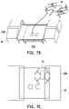
- FIGS. 7 A- 7 F is schematic diagrams showing the positioning process of the drone according to an embodiment of the present disclosure.
- FIG. 8 A is a schematic diagram of a power supply connector of the base station according to an embodiment of the present disclosure.
- FIG. 8 B is a schematic diagram of a charging connector of the drone according to an embodiment of the present disclosure.
- FIGS. 9 A and 9 B are schematic views of a temperature control system in accordance with an embodiment of the present disclosure.
- the description of “A” component facing “B” component herein may contain the situations that “A” component facing “B” component directly or one or more additional components is between “A” component and “B” component.
- the description of “A” component “adjacent to” “B” component herein may contain the situations that “A” component is directly “adjacent to” “B” component or one or more additional components is between “A” component and “B” component. Accordingly, the drawings and descriptions will be regarded as illustrative in nature and not as restrictive.
- FIG. 2 A is a schematic diagram of a monitoring system 1 in accordance with an embodiment of the present disclosure.
- the monitoring system 1 includes, at least but not limited to, a drone 10 , a monitor server 30 , and a base station 50 .
- FIG. 2 B is a schematic diagram of an automated monitoring method in accordance with an embodiment of the present disclosure.
- the monitoring system could be installed at a specific place for environmental monitoring.
- the monitoring system 1 may include the drone 10 and the base station 50 having a charging device. When the drone 10 performs automated monitoring of the area, the drone 10 repeats the two operational processes of patrol detecting and recharging after returning. As shown in FIG.
- the drone 10 is located at the base station 50 (step S 110 ). After the battery of the drone 10 is fully charged, protective covers of the base station 50 are automatically opened, so that the drone 10 can fly out for patrol detection (step S 120 ). The drone 10 returns and the protective covers of the base station 50 is notified to open (step S 130 ). After the drone 10 has been landed at the base station 50 , the protective covers of the base station 50 are closed and the drone 10 is charged (step S 140 ).
- the drone 10 includes at least but not limited to a battery 11 , a charging connector 12 , a sensor 13 , a communication transceiver 15 , a satellite locator 17 , an infrared emitter 18 , and a processor 19 .
- the battery 11 may be a lithium battery, a fuel battery, a nickel cadmium battery, a nickel hydride battery, or other rechargeable batteries, and the battery 11 is not limited thereto.
- the charging connector 12 may be a metal terminal, a jack, a pin header, a plug, or other various types of connector.
- the metal terminal is used for charging in a contact manner.
- the sensor 13 may be various sensors for detecting, for example, temperature, image, air pressure, humidity, and the like.
- the communication transceiver 15 could be a transceiver that supports wireless communication technology such as Wi-Fi, fourth generation (4G) or further generations of mobile communication.
- wireless communication technology such as Wi-Fi, fourth generation (4G) or further generations of mobile communication.
- the satellite locator 17 may be a receiver supporting a satellite positioning system such as a Beidou satellite navigation system, a Global Positioning System (GPS), or a Galileo positioning system.
- a satellite positioning system such as a Beidou satellite navigation system, a Global Positioning System (GPS), or a Galileo positioning system.
- the infrared emitter 18 is used to emit infrared lights.
- the processor 19 is coupled to the battery 11 , the sensor 13 , the communication transceiver 15 , the satellite locator 17 , and the infrared emitter 18 .
- the processor 19 may be a central processing unit (CPU), a microcontroller, chip programmable controller, Application-Specific Integrated Circuit (ASIC), Field Programmable Gate Array (FPGA) or other similar components, or combinations of the above components.
- the monitoring server 30 could be a desktop computer, a notebook computer, a workstation, or various types of servers.
- the monitoring server 30 has a communication transceiver the same as or compliant with the communication transceiver 15 of the drone 10 , for receiving electrical signals from the drone 10 .
- the monitoring server 30 further includes an input device (e.g., a keyboard, a mouse, a touch screen, etc.) and a display (e.g., a Liquid-Crystal Display (LCD), a light-emitting diode (LED), an organic light-emitting diode (OLED), etc.), with which a monitoring personnel may control the drone 10 and monitor the image recorded by the drone 10 .
- LCD Liquid-Crystal Display
- LED light-emitting diode
- OLED organic light-emitting diode
- the base station 50 includes, at least but not limited to, a charging device 51 , a positioning device 53 , a temperature control system 55 , an environmental monitoring system 57 , a control device 58 , and a communication transceiver 59 .
- the base station 50 has a platform 532 disposed at the main body of the base station 50 .
- Protective covers 534 are disposed on the main body of the base station 50 and may be laterally moved relative to the platform 532 (a lateral direction is defined as left or right directions in FIG. 5 B ). When the two protective covers 534 are closed (as shown in FIG.
- an inner space is formed inside by the surrounding main body of the base station 50 , the platform 532 and the protective covers 534 , so that the drone 10 located in the inner space would not be affected from outside.
- the two protective covers 534 are opened (as shown in FIG. 5 B ), the platform 532 is exposed, so that the drone 10 may leave from the platform 532 .
- the charging device 51 includes, at least but not limited to, a power supply 511 , a power supply connector 512 , a backup power supply 513 , and a power controller 515 .
- the power supply 511 could be grid power, an electric generator, or a battery the same as like the battery 11 of the drone 10 .
- the power supply connector 512 could be a terminal, a jack, a pin, a plug, a charging pad, or other connectors, and could be exposed on the platform 532 for connecting to the charging connector 12 of the drone 10 and electrically connecting to the power supply 511 .
- the backup power supply 513 may be an uninterruptible power system (UPS), an electric generator, a solar panel, or a combination of the two or more of the above.
- the power controller 515 can be a processor, a chip, or a circuit.
- the power controller 515 is connected to the power supply 511 , the power supply connector 512 , and the backup power supply 513 , so that the power supply 511 supplies electric power to the connected drone 10 through the power supply connector 512 , or the power controller 515 controls the backup power supply 513 to supply electric power to the drone 10 .
- the positioning device 53 includes, at least but not limited to, an image sensor 531 , a positioning structure 533 , and a positioning processor 535 .
- the image sensor 531 can be a camera, a video camera, or an infrared receiver. In this embodiment, the image sensor 531 receives or detects infrared lights emitted by the infrared emitter 18 , and is used to determine the distance relative to the infrared emitter 18 accordingly.
- the positioning structure 533 can be a fixed or moveable member (e.g., a rod, bracket, etc.).
- the positioning processor 535 can be a processor, a chip, or a circuit.
- the positioning processor 535 is coupled to the image sensor 531 and the positioning structure 533 to obtain the sensing data of the image sensor 531 and control the operation of the positioning structure 533 , such that the position of the drone 10 is fixed and the charging connector 12 of the drone 10 is aligned with the power supply connector 512 on the platform 532 , so as to supply electric power to the drone 10 .
- the temperature control system 55 includes, at least but not limited to, fans 551 , a temperature detector 553 , a heating device 555 , and a temperature control processor 557 .
- the fans 551 may include a axial-flow fan, a centrifugal fan, an interleaving fan, or other types of fan to allow air to flow.
- the temperature detector 553 can be disposed in the inner space formed by the protective covers 534 as shown in FIG. 5 A to detect the temperature of the inner space.
- the heating device 555 may be a type of heater using infrared radiation, electromagnetic, electrical resistance or the like, a heating sheet, a heating rod, a heating plate, or a combination thereof, and the heating device 555 may be disposed under the platform 532 or disposed around the protective covers 534 .
- the temperature control processor 557 may be a processor, a chip or a circuit. The temperature control processor 557 is connected to the fans 551 , the temperature detector 553 , and the heating device 555 , so that the temperature control processor 557 may obtain the temperature detected by the temperature detector 553 , so as to control the fans 551 and the heating device 555 to be powered on or powered off.
- the environmental monitoring system 57 includes, at least but not limited to, an external sensor 571 and an environmental control processor 573 disposed outside the base station 50 .
- the external sensor 571 can be various sensors of temperature, wind speed, precipitation, image, atmospheric pressure, humidity, and the like.
- the environmental control processor 573 can be a processor, a chip, or a circuit.
- the environmental control processor 573 is connected to the external sensor 571 to receive the sensing data generated by the external sensor 571 (e.g., temperature, wind speed, precipitation, etc.).
- the control device 58 is disposed in the base station 50 and in a space below the platform 532 .
- the control device 58 may be a microcomputer, a workstation, and the control device 58 includes, at least but not limited to, a storage device 581 and a processor 583 .
- the storage device 581 could be any type of fixed or removable random access memory (RAM), read-only memory (ROM), flash memory (flash memory) or the like or a combination thereof.
- the storage device 581 is used to store temporary or permanent data, sensed data, control commands, etc., and the details thereof are to be described in detail in subsequent embodiments.
- the implementation of the processor 583 may be referred to the processor 19 , and details thereof are omitted.
- the processor 583 is connected to the storage device 581 to access data stored in the storage device 581 .
- the implementation of the communication transceiver 59 may be referred to the communication transceiver 15 , and details thereof are omitted.
- the processor 583 is coupled to the communication transceiver 59 for communication with the drone 10 via the communication transceiver 59 .
- the processor 583 also controls communication among the various devices and systems 51 - 57 .
- some or all of the power controller 515 , the positioning processor 535 , the temperature control processor 557 , the environmentally controlled processor 573 , and the processor 583 of the base station 50 may be integrated, to control the operation of the corresponding devices or system 51 - 57 .
- appearances, numbers, and positions of the devices shown in FIGS. 5 A- 5 E may be changed according to requirements, and any modification is not limited in the embodiments of the present disclosure.
- the operation procedure of the monitoring system 1 in the embodiment of the present disclosure will be described in detail below.
- the method described in the embodiments of the present disclosure will be described in conjunction with various devices in the monitoring system 1 , the drone 10 , and various components and modules of the base station 50 .
- the various processes of the method may be adjusted according to the implementation situation, and are not limited thereto.
- FIG. 6 is a flow chart of a monitoring method of the monitoring system 1 according to an embodiment of the present disclosure.
- the power controller 515 is used to determine the battery specification of the battery 11 of the drone 10 based on the contact connection of the power supply connector 512 of the base station 50 and the charging connector 12 (Step S 610 ).
- the platform 532 of the base station 50 is provided with two charging boards 512 A and 512 B (forming the power supply connector 512 ), and the drone 10 is provided with charging terminals 12 A and 12 B extending downward (forming the charging connector 12 ).
- the drone 10 When the drone 10 is landed on the platform 532 , the drone 10 is moved to a fixed position by using the positioning structure 533 such that the charging connector 12 is connected to the power supply connector 512 (as shown in FIG. 7 F ).
- the power controller 515 can be used to determine whether the charging connector 12 and the power supply connector 512 are conducted by using a specific chip, an integrated circuit, a circuit, or additional electric power sensors.
- the power controller 515 After the charging connector 12 and the power supply connector 512 are confirmed to be in conduction (i.e., electrical connection), the power controller 515 starts an automated charging program and detects the electrical characteristics (e.g., voltage, current, impedance, polarity, etc.) of the current through the power supply connecter 512 , so as to determine the battery specification (for example, cell property, capacity, support voltage or current, charging mode, fast charge function, remaining electricity, etc.) of the battery 11 of the drone 10 .
- a sensing resistor is disposed with the power controller 515 for measuring the charging current.
- the power controller 515 can calculate the electricity information of the battery 11 (the amount of the electricity) according to the voltage difference between two ends of the sensing resistor.
- the power controller 515 can conduct to charge the battery 11 from the according to the battery specification (step S 630 ).
- the power controller 515 is used to determine the electricity of the battery 11 and adjust the power supply 511 to charge the battery 11 according to the remaining electricity and different battery specifications (step S 650 ).
- the power controller 515 adjusts the voltage and/or current supplied from the power supply 511 according to the battery specification, as the remaining electricity of the battery 11 changes. For example, if the remaining electricity of the battery 11 reaches 80%, the charging voltage and current are lowered. When the remaining electricity of the battery 11 reaches 100%, the charging voltage and current are turned down to zero (i.e., charging is stopped).
- the power controller 515 is used to determine the polarity of the charging connector 12 and switches the charging polarity of the power supply connector 512 according to the polarity of the charging connector 12 , such that the charging polarity of the power supply connector 512 matches the polarity of the charging connector 12 .
- the power supply connector 512 and the charging connector 12 are provided with positive and negative terminals. The orientation of the drone 10 may change after landing on the platform 532 , so the positive and negative poles of the power supply connector 512 may not be connected to the positive and negative poles of the charging connector 12 properly.
- the power controller 515 is used to determine whether the polarity of the positive and negative terminals of the charging connector 12 matches the charging polarity of positive and negative terminals of the connected power supply connector 512 , respectively. If the polarity are different from the charging polarity (not matched), the power controller 515 can change the charging polarity of the power supply connector 512 via a switching circuit or a chip configuration. For example, the positive terminal is switched to be a negative pole, and the negative terminal is switched to be a positive pole.
- the power supply connector 512 activates the power supply 511 to charge the battery 11 . Thereby, a charging failure or a short circuit caused by a polarity error of the charging connector 12 could be prevented.
- the power controller 515 of the charging device 51 is used to determine whether the power supply 511 is in an abnormal situation for charging the battery 11 , and the electric power may be stopped from being supplied from the power supply 511 according to the abnormal situation. Specifically, during the charging process, abnormal situations, such as a high temperature, an excessive current, and a short circuit, may occur. When the power controller 515 detects these abnormal situations, which can be evaluated according to the electric property and the battery specification, the power controller 515 can stop supplying electric power (for example, the voltage or the current may be reduced to zero). When the power controller 515 does not detect any abnormal situation, the electric power can be supplied again.
- the base station 50 may utilize a wireless charging technology to provide electric power for the battery 11 of the drone 10 , and the drone 10 and the base station 50 need to be installed with wireless charging devices corresponding to each other.
- the battery 11 of the drone 10 is separable, and the base station 50 is provided with a robotic arm to remove the battery 11 of the drone 10 and replace the battery 11 with another fully charged battery stored at the base station 50 .
- the monitoring system 1 may perform other functions described below.
- the sensor 13 of the drone 10 obtains sensing data, or the satellite locator 17 can obtain the location information of the drone 10 .
- the sensing data may be information such as images, temperatures, air pressures, electricity, etc.
- the processor 19 of the drone 10 can transmit the obtained sensing data and the location information of the drone 10 by using the communication transceiver 15 .
- the monitoring server 30 and/or the base station 50 can receive the sensing data and location information provided by the drone 10 , and the monitor server 30 and/or the base station 50 can transmit a control command.
- the control command may be obtained by an input device of the monitoring server 30 in accordance with operations of the monitoring personnel, or the control command may be a pre-defined rule of the monitoring server 30 and the base station 50 .
- the control command is, for example, a command of moving to a specific location, taking a photo at a specific time, a patrolling path, etc., depending on the needs of the application.
- the communication transceiver 15 of the drone 10 receives the control command, so that the drone 10 operate in accordance with the control command.
- the drone 10 may report a message and notify the monitoring server 30 .
- the monitoring personnel can switch the monitoring server 30 to a manual mode, to operate the drone 10 to perform a corresponding disposal procedure.
- the monitoring server 30 and/or the base station 50 can further back up, analyze or integrate the sensing data from the drone 10 , and the monitoring server 30 can also present the analysis results to the monitoring personnel using a display.
- the monitoring server 30 can also remotely and real-timely control the operations of the devices and systems 51 - 59 in the base station 50 and obtain operation status information.
- the process that the drone 10 returns to the base station 50 and lands on the landing platform 532 may include three sub-processes according to the embodiment of the present disclosure.
- the first sub-process is satellite positioning.
- the satellite locator 17 obtains the location information of the drone 10
- the processor 19 controls the drone 10 to move and fly above the base station 50 according to the location information of the drone 10 and the base station 50 .
- the drone 10 flies to a position away from the top side of the protective cover 534 of the base station 50 by a height greater than a certain distance, such as 15, 20 or 30 meters.
- the second sub-process is infrared positioning.
- the processor 19 switches the positioning mode to the infrared positioning.
- the image sensor 531 of the base station 50 detects the infrared light emitted by the infrared emitter 18 , and the positioning processor 535 obtains the relative position of the drone 10 according to the received infrared light.
- the positioning processor 535 transmits a control command related to movement of the drone 10 via the communication transceiver 59 , to control the drone 10 to move toward the platform 532 and finally land on the platform 532 of the base station 50 .
- the third sub-process is structure positioning.
- the left and right directions of the drawing are defined as a lateral direction (i.e., the Y axis), and the up and down directions of the drawing are defined as a longitudinal direction (i.e., the X axis).
- the positioning structure 533 includes longitudinal moving members 533 A longitudinally movably disposed on the platform 532 , and lateral moving members 533 B laterally movably disposed on the platform 532 .
- the structure positioning includes two steps, where the first step is Y-axis positioning, and the second step is X-axis positioning. Referring to FIGS. 7 D, 7 E and 7 F , the longitudinal moving members 533 A are fixed with the protective covers 534 and may be moved together with the protective cover 534 .
- the lateral moving members 533 B are fixed with the protective cover 534 and may be moved together with the protective covers 534 .
- the protective cover 534 drives the longitudinal moving members 533 A to move in the opposite directions D 1 (perpendicular to the opposite directions D 2 ), and the drone 10 is pushed into the center of the platform 532 in the Y-axis direction.
- the lateral moving members 533 B are fixed with the protective cover 534 .
- the positioning processor 535 controls the protective covers 534 to be closed the lateral moving members 533 B push the drone 10 toward the center of the platform 532 in the X-axis direction.
- the power supply connector 512 contacts and connects with the charging connector 12 .
- the positioning structure 533 on the base station 50 can be designed as different structures.
- the left and right directions of the drawing are defined as the lateral direction (i.e., the Y axis), and the up and low directions of the figure are defined as longitudinal direction (i.e., X-axis).
- the positioning structure 533 includes longitudinal moving members 533 A longitudinally movably disposed on the platform 532 , and laterally moving members 533 B laterally movably disposed on the platform 532 .
- the longitudinal moving members 533 A and the lateral moving members 533 B are driven by two motors, respectively.
- the longitudinal moving members 533 A move toward the opposite directions D 1 (perpendicular to the opposite directions D 2 ) to push the drone 10 toward the center of the platform 532 in the Y-axis direction
- the lateral moving members 533 B push the drone 10 toward the center of the platform 532 in the X-axis direction.
- the positioning processor 535 turns on the infrared emitter 18 on the drone 10 , so that the positioning processor 535 knows the relative position of the drone 10 , and the drone 10 is exactly placed at the charging position.
- the processor 19 activates break switch for the battery 11 on the drone 10 .
- the drone 10 also notifies the base station 50 to activate a charging switch for charging.
- the fans 551 includes an intake fan 551 A disposed at one side of the base station 50 , an exhaust fan 551 B disposed at another side of the base station 50 , and a lateral flow fan 551 C disposed above the platform 532 .
- the heating device 555 includes a heater 555 A disposed above the platform 532 , and heating pads 555 B disposed on the platform 532 .
- the temperature detector 553 obtains the inner temperature of the inner space (which is the space formed inside the base station 50 as shown in FIG. 9 A ) of the base station 50 .
- the temperature control processor 557 is used to control the powers and the amount of the air flow of the fans 551 A, 551 B and/or 551 C, to control the heating device 555 to be powered on or off, and to control the heating time of the heating device 555 according to the inner temperature, so that the heater 555 A and/or the heating pad 555 B of the heating device 555 may generate thermal energy.
- the temperature control processor 557 has different corresponding control modes.
- a high temperature environment when the temperature detector 553 detects that the inner temperature is higher than a high temperature threshold (the preset threshold), the temperature control processor 557 turns on the intake fan 551 A and the exhaust fan 551 B to form a heat dissipation airflow CF. Therefore, the heat in inner space of the base station 50 is dissipated.
- a low temperature environment when the temperature detector 553 detects that the inner temperature is lower than a low temperature threshold, the temperature control processor 557 turns off (or does not start) the intake fan 551 A and the exhaust fan 551 B, and turns on the heating pad 555 B.
- the heating pad 555 B generates thermal energy to heat the inner space of the base station 50 .
- the temperature control processor 557 may open the lateral flow fan 551 C and the heater 555 A, or simultaneously turn on the heating pad 555 B.
- the hot air generated by the heater 555 A flows into the inner space of the base station 50 through the lateral flow fan 551 C and returns to the lateral flow fan 551 C, so that the hot air flow HF is thermally circulated in the inner space of the base station 50 .
- the inner structure of the base station 50 can be prevented from being frozen, and problems that the protective covers 534 cannot be opened can be avoided. If the outside of the base station 50 begins to snow, hot air is conducted to the protective covers 534 , which also prevents snow from accumulating on the protective covers 534 and a damage on the protective cover 534 may be avoided.
- the external sensor 571 acquires environmental sensing data (for example, precipitation, wind speed, humidity, temperature, etc.) outside the base station 50 .
- the environmentally controlled processor 573 controls the operation of the drone 50 or other devices or systems 51 - 55 , 59 based on environmental sensing data. For example, when the external sensor 571 detects that a wind speed is higher than a wind speed threshold, the environmental control processor 573 sends a control command via the communication transceiver 59 to control the drone 10 to continue to stay on the platform 532 without performing a patrol task.
- the positioning processor 535 may continuously close the protective covers 534 , so that the drone 10 may be fixed on the positioning structure 533 .
- the environmental control processor 573 sends a control command via the communication transceiver 59 of the control device 58 , so that the drone 10 can return to the base station 50 or land at other base stations 50 .
- the environmental control processor 573 sends a control command via the communication transceiver 59 of the control device 58 , so that the drone 10 can return to the base station 50 or land at other base stations 50 .
- the base station 50 is installed with a UPS, an electric generator, a solar panel, or a combination thereof depending on the situations in use.
- the UPS is first enabled, such that the cruise monitoring system of the base station 50 does not crash due to a momentary power outage.
- the electric generator is started, to continue to provide electric power, and the system operation can be maintained.
- the base station 50 can also use solar panels as a continuous source of electric power.
- the base station of the embodiment of the present disclosure can be used to determine the battery specification of the drone and adjust the charging characteristics according to the battery specification, thereby providing a high-efficiency charging.
- the charging polarity of the base station is automatically adjusted according to the polarity of the charging connector of the drone, thereby the charging protection may be enhanced and the short circuit problem caused by error charging of incorrect polarity when the drone is landing may be avoided.
- the embodiments of the present disclosure improve the accuracy of the landing of the drone through three positioning modes of satellite, infrared, and mechanical mechanism.
- the base station is equipped with fans and heating devices, to be adapted to different temperatures.
- the drone can also automatically cruise and automatically charge.
- the base station Since the base station is set in an outdoor environment, external weather situations may affect the stability of the drone during cruise. With the environmental monitoring system, the base station may be able to evaluate climatic situations of the external environment and automatically adjust the most suitable cruise parameters for the drone. Furthermore, instead of the monitoring personnel, the embodiments of the present disclosure may perform the uninterrupted automated area monitoring. In order to avoid the situation that the base station of drone stops working in case that the electric power is lost, the base station is installed with a back-up power supply, such that the operation of the monitoring system may be continued.
- the term “the invention”, “the present invention” or the like does not necessarily limit the claim scope to a specific embodiment, and the reference to particularly preferred exemplary embodiments of the invention does not imply a limitation on the invention, and no such limitation is to be inferred.
- the invention is limited only by the spirit and scope of the appended claims. Moreover, these claims may refer to use “first”, “second”, etc. following with noun or element. Such terms should be understood as a nomenclature and should not be construed as giving the limitation on the number of the elements modified by such nomenclature unless specific number has been given.
- the abstract of the disclosure is provided to comply with the rules requiring an abstract, which will allow a searcher to quickly ascertain the subject matter of the technical disclosure of any patent issued from this disclosure.
Landscapes
- Engineering & Computer Science (AREA)
- Aviation & Aerospace Engineering (AREA)
- Transportation (AREA)
- Remote Sensing (AREA)
- Physics & Mathematics (AREA)
- Mechanical Engineering (AREA)
- Power Engineering (AREA)
- General Physics & Mathematics (AREA)
- Chemical & Material Sciences (AREA)
- Combustion & Propulsion (AREA)
- Radar, Positioning & Navigation (AREA)
- Automation & Control Theory (AREA)
- Charge And Discharge Circuits For Batteries Or The Like (AREA)
- Life Sciences & Earth Sciences (AREA)
- Atmospheric Sciences (AREA)
Abstract
Description
Claims (27)
Applications Claiming Priority (2)
| Application Number | Priority Date | Filing Date | Title |
|---|---|---|---|
| CN201810705841.0A CN110673625B (en) | 2018-07-02 | 2018-07-02 | Unmanned aerial vehicle monitoring system, base station and control method |
| CN201810705841.0 | 2018-07-02 |
Publications (2)
| Publication Number | Publication Date |
|---|---|
| US20200001735A1 US20200001735A1 (en) | 2020-01-02 |
| US11524596B2 true US11524596B2 (en) | 2022-12-13 |
Family
ID=69007908
Family Applications (1)
| Application Number | Title | Priority Date | Filing Date |
|---|---|---|---|
| US16/402,225 Active 2041-04-23 US11524596B2 (en) | 2018-07-02 | 2019-05-02 | Monitoring system, base station and control method of a drone |
Country Status (2)
| Country | Link |
|---|---|
| US (1) | US11524596B2 (en) |
| CN (1) | CN110673625B (en) |
Cited By (2)
| Publication number | Priority date | Publication date | Assignee | Title |
|---|---|---|---|---|
| US20210399555A1 (en) * | 2020-06-18 | 2021-12-23 | Globe (jiangsu) Co., Ltd. | Charge control circuit, charging device and charging system |
| US20220024578A1 (en) * | 2020-07-25 | 2022-01-27 | Jianfei Ye | Integrated engineering system that combines multiple drones and an Electro-Mechanical drone transportation system to achieve a new method of aviation transportation |
Families Citing this family (36)
| Publication number | Priority date | Publication date | Assignee | Title |
|---|---|---|---|---|
| WO2016072116A1 (en) * | 2014-11-07 | 2016-05-12 | ソニー株式会社 | Control system, control method, and storage medium |
| US10304342B2 (en) * | 2016-11-08 | 2019-05-28 | Ge Aviation Systems Llc | Ground-based data acquisition system |
| US11365113B2 (en) | 2017-03-07 | 2022-06-21 | Franklin Fueling Systems, Llc | Method and apparatus for limiting acidic corrosion and contamination in fuel delivery systems |
| US11111033B1 (en) * | 2017-05-12 | 2021-09-07 | Phirst Technologies, Llc | Unmanned aerial vehicle recharging system |
| AU2019213466A1 (en) * | 2018-02-05 | 2020-09-17 | H3 Dynamics Holdings Pte. Ltd. | Landing platform with improved charging for unmanned vehicles |
| GB2591733B (en) * | 2019-12-23 | 2022-06-29 | Sita Information Networking Computing Uk Ltd | Weather drone |
| JP7562973B2 (en) * | 2020-03-30 | 2024-10-08 | 株式会社Gsユアサ | Charging device and charging system for unmanned aerial vehicles |
| DE102020205087A1 (en) * | 2020-04-22 | 2021-10-28 | Volkswagen Aktiengesellschaft | Method for operating a flying object and a flying object |
| CN111786470B (en) * | 2020-06-29 | 2023-01-31 | 哈尔滨工业大学 | A UAV swarm wireless charging circuit topology and power flow control method |
| US20220080478A1 (en) * | 2020-09-14 | 2022-03-17 | Shang-Jung Wu | Management station of multi-point time-sharing water quality monitoring system |
| CN116348379A (en) * | 2020-09-16 | 2023-06-27 | 德潘徳恩特无人机独立系统有限责任公司 | A backoffice station for unmanned aerial vehicle |
| CN112406607B (en) * | 2020-10-15 | 2022-12-06 | 大强信息技术(深圳)有限公司 | Unmanned aerial vehicle platform that independently charges |
| CA3191062A1 (en) * | 2021-02-01 | 2022-08-04 | Chirag Shah | Method and system to ascertain location of drone box for stabilized landing and charging of drone |
| CN112895932B (en) * | 2021-05-06 | 2021-07-09 | 南京姆森自动化技术有限公司 | Plant protection unmanned aerial vehicle intelligent charging device |
| CN215476898U (en) * | 2021-06-07 | 2022-01-11 | 上海峰飞航空科技有限公司 | Unmanned aerial vehicle transport case |
| CN113353261B (en) * | 2021-07-22 | 2023-04-07 | 王淑娟 | Unmanned aerial vehicle special for environment monitoring |
| US11390178B1 (en) | 2021-08-20 | 2022-07-19 | Beta Air, Llc | Connector and method for use for authorizing battery charging for an electric vehicle |
| CN113628341B (en) * | 2021-08-31 | 2023-12-19 | 珠海尚方清洁能源科技有限公司 | Automatic monomer modeling method based on oblique photographic data and LIDAR point cloud fusion |
| CN113949162B (en) * | 2021-10-21 | 2024-06-04 | 广西科学院 | Island monitoring system and island monitoring method based on Beidou satellite |
| US20230312138A1 (en) * | 2021-10-31 | 2023-10-05 | Beta Air, Llc | System and method for recharging an electric vehicle |
| US11708000B2 (en) * | 2021-10-31 | 2023-07-25 | Beta Air, Llc | System and method for recharging an electric vehicle |
| US20230133477A1 (en) * | 2021-10-31 | 2023-05-04 | Beta Air, Llc | System and method for recharging an electric vehicle |
| CN114035425B (en) * | 2021-11-05 | 2022-07-26 | 广东工业大学 | A virtual-real state synchronization method and system for a UAV digital twin system |
| TWI800102B (en) * | 2021-11-16 | 2023-04-21 | 財團法人工業技術研究院 | Method and system for vehicle head compensation |
| CN114296367B (en) * | 2021-11-17 | 2023-07-21 | 山东省国土空间生态修复中心 | Remote telemetering acquisition device for land treatment |
| KR20230081895A (en) * | 2021-11-30 | 2023-06-08 | 현대모비스 주식회사 | Wireless charging method for urban air mobility and device and system therefor |
| KR20230081896A (en) * | 2021-11-30 | 2023-06-08 | 현대모비스 주식회사 | Wireless charging method for urban air mobility and device and system therefor |
| CN114390731A (en) * | 2021-12-16 | 2022-04-22 | 北京卓翼智能科技有限公司 | A heating control system for mooring unmanned aerial vehicle |
| CN114155694A (en) * | 2021-12-27 | 2022-03-08 | 北京卓翼智能科技有限公司 | An automatic cruise UAV with high temperature warning function |
| US11515714B1 (en) | 2021-12-28 | 2022-11-29 | Beta Air, Llc | Methods and systems for mitigating charging failure for an electric aircraft |
| CN114572019A (en) * | 2022-03-16 | 2022-06-03 | 深圳市大疆创新科技有限公司 | Method for charging movable platform, base station and movable platform system |
| FI131562B1 (en) * | 2022-04-22 | 2025-06-30 | Liikennevirta Oy / Virta Ltd | A scalable method to handle faults in a network of electric vehicle charging stations |
| US11685274B1 (en) * | 2022-08-16 | 2023-06-27 | Beta Air, Llc | Connector for charging an electric aircraft and a method for its use |
| CN116119064A (en) * | 2023-02-03 | 2023-05-16 | 深圳市道通智能航空技术股份有限公司 | UAV base station and UAV system |
| CN115924159B (en) * | 2023-03-10 | 2023-05-16 | 四川省天域航通科技有限公司 | Intelligent command control platform of large unmanned aerial vehicle and control method thereof |
| CN116395165B (en) * | 2023-06-08 | 2023-10-13 | 成都航空职业技术学院 | Relay planting unmanned aerial vehicle system and charging method thereof |
Citations (32)
| Publication number | Priority date | Publication date | Assignee | Title |
|---|---|---|---|---|
| CN104102248A (en) | 2014-07-02 | 2014-10-15 | 北京航空航天大学 | Unmanned aerial vehicle equipment cabin temperature control system capable of utilizing heat of engine |
| TW201532006A (en) | 2013-10-09 | 2015-08-16 | Sz Dji Technology Co Ltd | Remote control method and system |
| CN105539824A (en) | 2015-12-31 | 2016-05-04 | 东莞市吉飞机器人有限公司 | Intelligent drone system that can work continuously in a large area |
| CN105951614A (en) | 2016-05-03 | 2016-09-21 | 湖北工业大学 | Relay transduction service station for rotor unmanned aerial vehicle |
| CN106005463A (en) | 2016-06-28 | 2016-10-12 | 安庆市佰斯特电子科技有限公司 | Adjustable charging base special for unmanned aerial vehicle charging equipment |
| CN106209206A (en) | 2016-07-12 | 2016-12-07 | 上海与德通讯技术有限公司 | A kind of unmanned plane charging base station and system |
| CN206023324U (en) | 2016-09-21 | 2017-03-15 | 深圳市大疆创新科技有限公司 | Charge control system, charging device and unmanned plane |
| CN106542109A (en) | 2016-11-04 | 2017-03-29 | 上海云犀智能系统有限公司 | A kind of unmanned plane recharging platform |
| US20170111228A1 (en) | 2015-10-15 | 2017-04-20 | T-Mobile Usa, Inc. | Dynamic wireless communications network with a plurality of aerial drones |
| CN107078528A (en) | 2016-09-21 | 2017-08-18 | 深圳市大疆创新科技有限公司 | Charging method for power supply, charging control system, charging device and unmanned aerial vehicle |
| US20170320570A1 (en) | 2016-05-06 | 2017-11-09 | SKyX Limited | Unmanned aerial vehicle (uav) having vertical takeoff and landing (vtol) capability |
| CN107355983A (en) | 2017-07-21 | 2017-11-17 | 深圳市康宝耐电子科技有限公司 | Anemopyretic Heat preservation base |
| CN107640079A (en) | 2017-05-19 | 2018-01-30 | 成都天麒科技有限公司 | A kind of unmanned plane continuation of the journey support method |
| US20180029723A1 (en) | 2015-02-05 | 2018-02-01 | Airobotics Ltd. | Landing and charging system for drones |
| CN107672463A (en) | 2017-07-20 | 2018-02-09 | 国网浙江海宁市供电公司 | Aerial unmanned plane charging station arrangement and its charging method |
| US20180072170A1 (en) | 2016-09-09 | 2018-03-15 | Michael Steward Evans | Drone charging stations |
| US20180101173A1 (en) * | 2016-10-10 | 2018-04-12 | Qualcomm Incorporated | Systems and methods for landing a drone on a moving base |
| CN207242062U (en) | 2017-09-20 | 2018-04-17 | 成都天麒科技有限公司 | A kind of unmanned plane landing pedestal |
| EP3333064A1 (en) | 2016-12-07 | 2018-06-13 | AIRBUS HELICOPTERS DEUTSCHLAND GmbH | An aircraft with an airframe and at least one electrically powered thrust producing unit |
| WO2018107562A1 (en) | 2016-12-15 | 2018-06-21 | 深圳市元征科技股份有限公司 | Unmanned aerial vehicle, and unmanned aerial vehicle charging control method and system |
| CN108657455A (en) | 2018-04-27 | 2018-10-16 | 内蒙古工业大学 | A kind of unmanned plane automatic retraction device of HV Transmission Line Routing Inspection |
| CN108674291A (en) | 2018-05-21 | 2018-10-19 | 滨州学院 | A kind of draw off gear of vehicle-mounted unmanned aerial vehicle |
| US10124912B2 (en) * | 2014-01-02 | 2018-11-13 | Blacknight Holdings, Llc | Landing pad for unmanned aerial vehicle delivery |
| US20180327091A1 (en) * | 2017-05-12 | 2018-11-15 | Gencore Candeo, Ltd. | Systems and methods for response to emergency situations using unmanned airborne vehicles with improved functionalities |
| US20180366955A1 (en) * | 2017-06-14 | 2018-12-20 | Hadal, Inc. | Systems and methods for configurable battery charging |
| US20190172348A1 (en) * | 2016-09-02 | 2019-06-06 | FLIR Belgium BVBA | Unmanned aerial system assisted navigational systems and methods |
| US10488512B1 (en) * | 2016-04-08 | 2019-11-26 | Olaeris, Inc. | Landing guidance for remotely operated aerial vehicles using crossed radar beams |
| US20200207230A1 (en) * | 2018-12-26 | 2020-07-02 | Michael Steward Evans | Vehicle Traffic and Charge Management System Using Autonomous Cluster Networks of Vehicle Charging Stations |
| US20200239160A1 (en) * | 2019-01-28 | 2020-07-30 | Coretronic Intelligent Robotics Corporation | Monitoring system, base station and control method thereof |
| US20200239135A1 (en) * | 2019-01-28 | 2020-07-30 | Coretronic Intelligent Robotics Corporation | Monitoring system and control method thereof |
| US20200310465A1 (en) * | 2017-11-29 | 2020-10-01 | Ford Global Technologies, Llc | Uav landing systems and methods |
| US20210031947A1 (en) * | 2018-02-05 | 2021-02-04 | H3 Dynamics Holdings Pte. Ltd. | Landing platform with improved charging for unmanned vehicles |
Family Cites Families (1)
| Publication number | Priority date | Publication date | Assignee | Title |
|---|---|---|---|---|
| US8511606B1 (en) * | 2009-12-09 | 2013-08-20 | The Boeing Company | Unmanned aerial vehicle base station |
-
2018
- 2018-07-02 CN CN201810705841.0A patent/CN110673625B/en active Active
-
2019
- 2019-05-02 US US16/402,225 patent/US11524596B2/en active Active
Patent Citations (32)
| Publication number | Priority date | Publication date | Assignee | Title |
|---|---|---|---|---|
| TW201532006A (en) | 2013-10-09 | 2015-08-16 | Sz Dji Technology Co Ltd | Remote control method and system |
| US10124912B2 (en) * | 2014-01-02 | 2018-11-13 | Blacknight Holdings, Llc | Landing pad for unmanned aerial vehicle delivery |
| CN104102248A (en) | 2014-07-02 | 2014-10-15 | 北京航空航天大学 | Unmanned aerial vehicle equipment cabin temperature control system capable of utilizing heat of engine |
| US20180029723A1 (en) | 2015-02-05 | 2018-02-01 | Airobotics Ltd. | Landing and charging system for drones |
| US20170111228A1 (en) | 2015-10-15 | 2017-04-20 | T-Mobile Usa, Inc. | Dynamic wireless communications network with a plurality of aerial drones |
| CN105539824A (en) | 2015-12-31 | 2016-05-04 | 东莞市吉飞机器人有限公司 | Intelligent drone system that can work continuously in a large area |
| US10488512B1 (en) * | 2016-04-08 | 2019-11-26 | Olaeris, Inc. | Landing guidance for remotely operated aerial vehicles using crossed radar beams |
| CN105951614A (en) | 2016-05-03 | 2016-09-21 | 湖北工业大学 | Relay transduction service station for rotor unmanned aerial vehicle |
| US20170320570A1 (en) | 2016-05-06 | 2017-11-09 | SKyX Limited | Unmanned aerial vehicle (uav) having vertical takeoff and landing (vtol) capability |
| CN106005463A (en) | 2016-06-28 | 2016-10-12 | 安庆市佰斯特电子科技有限公司 | Adjustable charging base special for unmanned aerial vehicle charging equipment |
| CN106209206A (en) | 2016-07-12 | 2016-12-07 | 上海与德通讯技术有限公司 | A kind of unmanned plane charging base station and system |
| US20190172348A1 (en) * | 2016-09-02 | 2019-06-06 | FLIR Belgium BVBA | Unmanned aerial system assisted navigational systems and methods |
| US20180072170A1 (en) | 2016-09-09 | 2018-03-15 | Michael Steward Evans | Drone charging stations |
| CN206023324U (en) | 2016-09-21 | 2017-03-15 | 深圳市大疆创新科技有限公司 | Charge control system, charging device and unmanned plane |
| CN107078528A (en) | 2016-09-21 | 2017-08-18 | 深圳市大疆创新科技有限公司 | Charging method for power supply, charging control system, charging device and unmanned aerial vehicle |
| US20180101173A1 (en) * | 2016-10-10 | 2018-04-12 | Qualcomm Incorporated | Systems and methods for landing a drone on a moving base |
| CN106542109A (en) | 2016-11-04 | 2017-03-29 | 上海云犀智能系统有限公司 | A kind of unmanned plane recharging platform |
| EP3333064A1 (en) | 2016-12-07 | 2018-06-13 | AIRBUS HELICOPTERS DEUTSCHLAND GmbH | An aircraft with an airframe and at least one electrically powered thrust producing unit |
| WO2018107562A1 (en) | 2016-12-15 | 2018-06-21 | 深圳市元征科技股份有限公司 | Unmanned aerial vehicle, and unmanned aerial vehicle charging control method and system |
| US20180327091A1 (en) * | 2017-05-12 | 2018-11-15 | Gencore Candeo, Ltd. | Systems and methods for response to emergency situations using unmanned airborne vehicles with improved functionalities |
| CN107640079A (en) | 2017-05-19 | 2018-01-30 | 成都天麒科技有限公司 | A kind of unmanned plane continuation of the journey support method |
| US20180366955A1 (en) * | 2017-06-14 | 2018-12-20 | Hadal, Inc. | Systems and methods for configurable battery charging |
| CN107672463A (en) | 2017-07-20 | 2018-02-09 | 国网浙江海宁市供电公司 | Aerial unmanned plane charging station arrangement and its charging method |
| CN107355983A (en) | 2017-07-21 | 2017-11-17 | 深圳市康宝耐电子科技有限公司 | Anemopyretic Heat preservation base |
| CN207242062U (en) | 2017-09-20 | 2018-04-17 | 成都天麒科技有限公司 | A kind of unmanned plane landing pedestal |
| US20200310465A1 (en) * | 2017-11-29 | 2020-10-01 | Ford Global Technologies, Llc | Uav landing systems and methods |
| US20210031947A1 (en) * | 2018-02-05 | 2021-02-04 | H3 Dynamics Holdings Pte. Ltd. | Landing platform with improved charging for unmanned vehicles |
| CN108657455A (en) | 2018-04-27 | 2018-10-16 | 内蒙古工业大学 | A kind of unmanned plane automatic retraction device of HV Transmission Line Routing Inspection |
| CN108674291A (en) | 2018-05-21 | 2018-10-19 | 滨州学院 | A kind of draw off gear of vehicle-mounted unmanned aerial vehicle |
| US20200207230A1 (en) * | 2018-12-26 | 2020-07-02 | Michael Steward Evans | Vehicle Traffic and Charge Management System Using Autonomous Cluster Networks of Vehicle Charging Stations |
| US20200239160A1 (en) * | 2019-01-28 | 2020-07-30 | Coretronic Intelligent Robotics Corporation | Monitoring system, base station and control method thereof |
| US20200239135A1 (en) * | 2019-01-28 | 2020-07-30 | Coretronic Intelligent Robotics Corporation | Monitoring system and control method thereof |
Non-Patent Citations (1)
| Title |
|---|
| "Office Action of China Counterpart Application", dated Apr. 26, 2022, p. 1-p. 16. |
Cited By (4)
| Publication number | Priority date | Publication date | Assignee | Title |
|---|---|---|---|---|
| US20210399555A1 (en) * | 2020-06-18 | 2021-12-23 | Globe (jiangsu) Co., Ltd. | Charge control circuit, charging device and charging system |
| US12224604B2 (en) * | 2020-06-18 | 2025-02-11 | Globe (jiangsu) Co., Ltd. | Charge control circuit, charging device and charging system |
| US20220024578A1 (en) * | 2020-07-25 | 2022-01-27 | Jianfei Ye | Integrated engineering system that combines multiple drones and an Electro-Mechanical drone transportation system to achieve a new method of aviation transportation |
| US11958602B2 (en) * | 2020-07-25 | 2024-04-16 | Jianfei Ye | Integrated engineering system that combines multiple drones and an electro-mechanical drone transportation system to achieve a new method of aviation transportation |
Also Published As
| Publication number | Publication date |
|---|---|
| US20200001735A1 (en) | 2020-01-02 |
| CN110673625A (en) | 2020-01-10 |
| CN110673625B (en) | 2023-05-23 |
Similar Documents
| Publication | Publication Date | Title |
|---|---|---|
| US11524596B2 (en) | Monitoring system, base station and control method of a drone | |
| JP7157116B2 (en) | Battery and drone with battery | |
| JP7266902B2 (en) | Landing platform with improved charging for drones | |
| CN207028881U (en) | A kind of unmanned plane shuts down storehouse | |
| CN106873623B (en) | A rapid autonomous endurance system for unmanned aerial vehicles and method thereof | |
| KR102065097B1 (en) | Manless Flying Drone for Usage of Charing Electrical Vehicle and Charging System using the Same | |
| CN110850890A (en) | Photovoltaic power station UAV inspection system and its control method | |
| WO2019061533A1 (en) | Apron platform, unmanned aerial vehicle base station, and unmanned aerial vehicle landing method and system | |
| CN107176047A (en) | A kind of unmanned plane shuts down storehouse | |
| CN105951614A (en) | Relay transduction service station for rotor unmanned aerial vehicle | |
| CN106226620B (en) | A kind of power supply unit observation system | |
| US11413978B2 (en) | Battery charging system for drones | |
| CN108155595B (en) | Intelligent inspection system for cable trench of transformer substation | |
| CN207010361U (en) | An electric power automatic dispatching control device | |
| CN107820050A (en) | Conductive rail movable monitoring robot and its monitoring system and method | |
| CN108574332A (en) | A kind of unmanned aerial vehicle power supply system and its maintenance method, unmanned aerial vehicle charging method | |
| CN105786017A (en) | Photovoltaic power station survey, operation and maintenance system based on unmanned aerial vehicle | |
| CN107140194A (en) | A kind of many rotor railway automatic tour inspection systems of tracking for supporting automatic charging | |
| CN110647170A (en) | Navigation mark inspection device and method based on unmanned aerial vehicle | |
| CN109218683B (en) | Drone monitoring system and power site monitoring system | |
| CN119037764B (en) | A drone hangar and a drone control method | |
| Nieuwoudt et al. | Automated charging and docking station for security uavs | |
| CN208890455U (en) | A kind of unmanned plane power supply system | |
| CN212951176U (en) | Intelligent searching and transporting unmanned aerial vehicle base station | |
| CN105978619A (en) | Unattended land-based ADS-B receiving station and monitoring system |
Legal Events
| Date | Code | Title | Description |
|---|---|---|---|
| FEPP | Fee payment procedure |
Free format text: ENTITY STATUS SET TO UNDISCOUNTED (ORIGINAL EVENT CODE: BIG.); ENTITY STATUS OF PATENT OWNER: LARGE ENTITY |
|
| AS | Assignment |
Owner name: CORETRONIC INTELLIGENT ROBOTICS CORPORATION, TAIWAN Free format text: ASSIGNMENT OF ASSIGNORS INTEREST;ASSIGNORS:CHENG, HSU-CHIH;CHEN, YING-CHIEH;HSIEH, CHI-TONG;AND OTHERS;REEL/FRAME:049068/0883 Effective date: 20190502 Owner name: CORETRONIC INTELLIGENT ROBOTICS CORPORATION, TAIWAN Free format text: ASSIGNMENT OF ASSIGNORS INTEREST;ASSIGNORS:CHENG, HSU-CHIH;CHEN, YING-CHIEH;HSIEH, CHI-TONG;AND OTHERS;REEL/FRAME:049068/0880 Effective date: 20190502 Owner name: CORETRONIC INTELLIGENT ROBOTICS CORPORATION, TAIWA Free format text: ASSIGNMENT OF ASSIGNORS INTEREST;ASSIGNORS:CHENG, HSU-CHIH;CHEN, YING-CHIEH;HSIEH, CHI-TONG;AND OTHERS;REEL/FRAME:049068/0880 Effective date: 20190502 Owner name: CORETRONIC INTELLIGENT ROBOTICS CORPORATION, TAIWA Free format text: ASSIGNMENT OF ASSIGNORS INTEREST;ASSIGNORS:CHENG, HSU-CHIH;CHEN, YING-CHIEH;HSIEH, CHI-TONG;AND OTHERS;REEL/FRAME:049068/0883 Effective date: 20190502 |
|
| STPP | Information on status: patent application and granting procedure in general |
Free format text: DOCKETED NEW CASE - READY FOR EXAMINATION |
|
| STPP | Information on status: patent application and granting procedure in general |
Free format text: NON FINAL ACTION MAILED |
|
| STPP | Information on status: patent application and granting procedure in general |
Free format text: RESPONSE TO NON-FINAL OFFICE ACTION ENTERED AND FORWARDED TO EXAMINER |
|
| STPP | Information on status: patent application and granting procedure in general |
Free format text: NOTICE OF ALLOWANCE MAILED -- APPLICATION RECEIVED IN OFFICE OF PUBLICATIONS |
|
| STPP | Information on status: patent application and granting procedure in general |
Free format text: AWAITING TC RESP., ISSUE FEE NOT PAID |
|
| STPP | Information on status: patent application and granting procedure in general |
Free format text: NOTICE OF ALLOWANCE MAILED -- APPLICATION RECEIVED IN OFFICE OF PUBLICATIONS |
|
| STPP | Information on status: patent application and granting procedure in general |
Free format text: PUBLICATIONS -- ISSUE FEE PAYMENT VERIFIED |
|
| STCF | Information on status: patent grant |
Free format text: PATENTED CASE |