US11523972B2 - Apparatus, system and method for fluid delivery - Google Patents
Apparatus, system and method for fluid delivery Download PDFInfo
- Publication number
- US11523972B2 US11523972B2 US16/393,191 US201916393191A US11523972B2 US 11523972 B2 US11523972 B2 US 11523972B2 US 201916393191 A US201916393191 A US 201916393191A US 11523972 B2 US11523972 B2 US 11523972B2
- Authority
- US
- United States
- Prior art keywords
- assembly
- housing assembly
- disposable housing
- reservoir
- cover
- Prior art date
- Legal status (The legal status is an assumption and is not a legal conclusion. Google has not performed a legal analysis and makes no representation as to the accuracy of the status listed.)
- Active, expires
Links
Images


Classifications
-
- A—HUMAN NECESSITIES
- A61—MEDICAL OR VETERINARY SCIENCE; HYGIENE
- A61J—CONTAINERS SPECIALLY ADAPTED FOR MEDICAL OR PHARMACEUTICAL PURPOSES; DEVICES OR METHODS SPECIALLY ADAPTED FOR BRINGING PHARMACEUTICAL PRODUCTS INTO PARTICULAR PHYSICAL OR ADMINISTERING FORMS; DEVICES FOR ADMINISTERING FOOD OR MEDICINES ORALLY; BABY COMFORTERS; DEVICES FOR RECEIVING SPITTLE
- A61J1/00—Containers specially adapted for medical or pharmaceutical purposes
- A61J1/14—Details; Accessories therefor
- A61J1/20—Arrangements for transferring or mixing fluids, e.g. from vial to syringe
- A61J1/2003—Accessories used in combination with means for transfer or mixing of fluids, e.g. for activating fluid flow, separating fluids, filtering fluid or venting
- A61J1/2048—Connecting means
- A61J1/2065—Connecting means having aligning and guiding means
-
- A—HUMAN NECESSITIES
- A61—MEDICAL OR VETERINARY SCIENCE; HYGIENE
- A61M—DEVICES FOR INTRODUCING MEDIA INTO, OR ONTO, THE BODY; DEVICES FOR TRANSDUCING BODY MEDIA OR FOR TAKING MEDIA FROM THE BODY; DEVICES FOR PRODUCING OR ENDING SLEEP OR STUPOR
- A61M5/00—Devices for bringing media into the body in a subcutaneous, intra-vascular or intramuscular way; Accessories therefor, e.g. filling or cleaning devices, arm-rests
- A61M5/14—Infusion devices, e.g. infusing by gravity; Blood infusion; Accessories therefor
- A61M5/142—Pressure infusion, e.g. using pumps
-
- A—HUMAN NECESSITIES
- A61—MEDICAL OR VETERINARY SCIENCE; HYGIENE
- A61J—CONTAINERS SPECIALLY ADAPTED FOR MEDICAL OR PHARMACEUTICAL PURPOSES; DEVICES OR METHODS SPECIALLY ADAPTED FOR BRINGING PHARMACEUTICAL PRODUCTS INTO PARTICULAR PHYSICAL OR ADMINISTERING FORMS; DEVICES FOR ADMINISTERING FOOD OR MEDICINES ORALLY; BABY COMFORTERS; DEVICES FOR RECEIVING SPITTLE
- A61J1/00—Containers specially adapted for medical or pharmaceutical purposes
- A61J1/14—Details; Accessories therefor
- A61J1/1406—Septums, pierceable membranes
-
- A—HUMAN NECESSITIES
- A61—MEDICAL OR VETERINARY SCIENCE; HYGIENE
- A61J—CONTAINERS SPECIALLY ADAPTED FOR MEDICAL OR PHARMACEUTICAL PURPOSES; DEVICES OR METHODS SPECIALLY ADAPTED FOR BRINGING PHARMACEUTICAL PRODUCTS INTO PARTICULAR PHYSICAL OR ADMINISTERING FORMS; DEVICES FOR ADMINISTERING FOOD OR MEDICINES ORALLY; BABY COMFORTERS; DEVICES FOR RECEIVING SPITTLE
- A61J1/00—Containers specially adapted for medical or pharmaceutical purposes
- A61J1/14—Details; Accessories therefor
- A61J1/20—Arrangements for transferring or mixing fluids, e.g. from vial to syringe
- A61J1/2003—Accessories used in combination with means for transfer or mixing of fluids, e.g. for activating fluid flow, separating fluids, filtering fluid or venting
- A61J1/2006—Piercing means
- A61J1/201—Piercing means having one piercing end
-
- A—HUMAN NECESSITIES
- A61—MEDICAL OR VETERINARY SCIENCE; HYGIENE
- A61J—CONTAINERS SPECIALLY ADAPTED FOR MEDICAL OR PHARMACEUTICAL PURPOSES; DEVICES OR METHODS SPECIALLY ADAPTED FOR BRINGING PHARMACEUTICAL PRODUCTS INTO PARTICULAR PHYSICAL OR ADMINISTERING FORMS; DEVICES FOR ADMINISTERING FOOD OR MEDICINES ORALLY; BABY COMFORTERS; DEVICES FOR RECEIVING SPITTLE
- A61J1/00—Containers specially adapted for medical or pharmaceutical purposes
- A61J1/14—Details; Accessories therefor
- A61J1/20—Arrangements for transferring or mixing fluids, e.g. from vial to syringe
- A61J1/2003—Accessories used in combination with means for transfer or mixing of fluids, e.g. for activating fluid flow, separating fluids, filtering fluid or venting
- A61J1/202—Separating means
- A61J1/2037—Separating means having valve means
-
- A—HUMAN NECESSITIES
- A61—MEDICAL OR VETERINARY SCIENCE; HYGIENE
- A61M—DEVICES FOR INTRODUCING MEDIA INTO, OR ONTO, THE BODY; DEVICES FOR TRANSDUCING BODY MEDIA OR FOR TAKING MEDIA FROM THE BODY; DEVICES FOR PRODUCING OR ENDING SLEEP OR STUPOR
- A61M5/00—Devices for bringing media into the body in a subcutaneous, intra-vascular or intramuscular way; Accessories therefor, e.g. filling or cleaning devices, arm-rests
- A61M5/14—Infusion devices, e.g. infusing by gravity; Blood infusion; Accessories therefor
- A61M5/1413—Modular systems comprising interconnecting elements
-
- A—HUMAN NECESSITIES
- A61—MEDICAL OR VETERINARY SCIENCE; HYGIENE
- A61M—DEVICES FOR INTRODUCING MEDIA INTO, OR ONTO, THE BODY; DEVICES FOR TRANSDUCING BODY MEDIA OR FOR TAKING MEDIA FROM THE BODY; DEVICES FOR PRODUCING OR ENDING SLEEP OR STUPOR
- A61M5/00—Devices for bringing media into the body in a subcutaneous, intra-vascular or intramuscular way; Accessories therefor, e.g. filling or cleaning devices, arm-rests
- A61M5/14—Infusion devices, e.g. infusing by gravity; Blood infusion; Accessories therefor
- A61M5/142—Pressure infusion, e.g. using pumps
- A61M5/14244—Pressure infusion, e.g. using pumps adapted to be carried by the patient, e.g. portable on the body
- A61M5/14248—Pressure infusion, e.g. using pumps adapted to be carried by the patient, e.g. portable on the body of the skin patch type
-
- A—HUMAN NECESSITIES
- A61—MEDICAL OR VETERINARY SCIENCE; HYGIENE
- A61M—DEVICES FOR INTRODUCING MEDIA INTO, OR ONTO, THE BODY; DEVICES FOR TRANSDUCING BODY MEDIA OR FOR TAKING MEDIA FROM THE BODY; DEVICES FOR PRODUCING OR ENDING SLEEP OR STUPOR
- A61M5/00—Devices for bringing media into the body in a subcutaneous, intra-vascular or intramuscular way; Accessories therefor, e.g. filling or cleaning devices, arm-rests
- A61M5/14—Infusion devices, e.g. infusing by gravity; Blood infusion; Accessories therefor
- A61M5/142—Pressure infusion, e.g. using pumps
- A61M5/145—Pressure infusion, e.g. using pumps using pressurised reservoirs, e.g. pressurised by means of pistons
- A61M5/1452—Pressure infusion, e.g. using pumps using pressurised reservoirs, e.g. pressurised by means of pistons pressurised by means of pistons
-
- A—HUMAN NECESSITIES
- A61—MEDICAL OR VETERINARY SCIENCE; HYGIENE
- A61M—DEVICES FOR INTRODUCING MEDIA INTO, OR ONTO, THE BODY; DEVICES FOR TRANSDUCING BODY MEDIA OR FOR TAKING MEDIA FROM THE BODY; DEVICES FOR PRODUCING OR ENDING SLEEP OR STUPOR
- A61M5/00—Devices for bringing media into the body in a subcutaneous, intra-vascular or intramuscular way; Accessories therefor, e.g. filling or cleaning devices, arm-rests
- A61M5/14—Infusion devices, e.g. infusing by gravity; Blood infusion; Accessories therefor
- A61M5/168—Means for controlling media flow to the body or for metering media to the body, e.g. drip meters, counters ; Monitoring media flow to the body
- A61M5/16831—Monitoring, detecting, signalling or eliminating infusion flow anomalies
-
- A—HUMAN NECESSITIES
- A61—MEDICAL OR VETERINARY SCIENCE; HYGIENE
- A61M—DEVICES FOR INTRODUCING MEDIA INTO, OR ONTO, THE BODY; DEVICES FOR TRANSDUCING BODY MEDIA OR FOR TAKING MEDIA FROM THE BODY; DEVICES FOR PRODUCING OR ENDING SLEEP OR STUPOR
- A61M5/00—Devices for bringing media into the body in a subcutaneous, intra-vascular or intramuscular way; Accessories therefor, e.g. filling or cleaning devices, arm-rests
- A61M5/14—Infusion devices, e.g. infusing by gravity; Blood infusion; Accessories therefor
- A61M5/168—Means for controlling media flow to the body or for metering media to the body, e.g. drip meters, counters ; Monitoring media flow to the body
- A61M5/172—Means for controlling media flow to the body or for metering media to the body, e.g. drip meters, counters ; Monitoring media flow to the body electrical or electronic
- A61M5/1723—Means for controlling media flow to the body or for metering media to the body, e.g. drip meters, counters ; Monitoring media flow to the body electrical or electronic using feedback of body parameters, e.g. blood-sugar, pressure
-
- A—HUMAN NECESSITIES
- A61—MEDICAL OR VETERINARY SCIENCE; HYGIENE
- A61M—DEVICES FOR INTRODUCING MEDIA INTO, OR ONTO, THE BODY; DEVICES FOR TRANSDUCING BODY MEDIA OR FOR TAKING MEDIA FROM THE BODY; DEVICES FOR PRODUCING OR ENDING SLEEP OR STUPOR
- A61M5/00—Devices for bringing media into the body in a subcutaneous, intra-vascular or intramuscular way; Accessories therefor, e.g. filling or cleaning devices, arm-rests
- A61M5/14—Infusion devices, e.g. infusing by gravity; Blood infusion; Accessories therefor
- A61M2005/1401—Functional features
- A61M2005/1402—Priming
-
- A—HUMAN NECESSITIES
- A61—MEDICAL OR VETERINARY SCIENCE; HYGIENE
- A61M—DEVICES FOR INTRODUCING MEDIA INTO, OR ONTO, THE BODY; DEVICES FOR TRANSDUCING BODY MEDIA OR FOR TAKING MEDIA FROM THE BODY; DEVICES FOR PRODUCING OR ENDING SLEEP OR STUPOR
- A61M5/00—Devices for bringing media into the body in a subcutaneous, intra-vascular or intramuscular way; Accessories therefor, e.g. filling or cleaning devices, arm-rests
- A61M5/14—Infusion devices, e.g. infusing by gravity; Blood infusion; Accessories therefor
- A61M5/168—Means for controlling media flow to the body or for metering media to the body, e.g. drip meters, counters ; Monitoring media flow to the body
- A61M5/16831—Monitoring, detecting, signalling or eliminating infusion flow anomalies
- A61M2005/16863—Occlusion detection
-
- A—HUMAN NECESSITIES
- A61—MEDICAL OR VETERINARY SCIENCE; HYGIENE
- A61M—DEVICES FOR INTRODUCING MEDIA INTO, OR ONTO, THE BODY; DEVICES FOR TRANSDUCING BODY MEDIA OR FOR TAKING MEDIA FROM THE BODY; DEVICES FOR PRODUCING OR ENDING SLEEP OR STUPOR
- A61M5/00—Devices for bringing media into the body in a subcutaneous, intra-vascular or intramuscular way; Accessories therefor, e.g. filling or cleaning devices, arm-rests
- A61M5/178—Syringes
- A61M5/31—Details
- A61M2005/3114—Filling or refilling
-
- A—HUMAN NECESSITIES
- A61—MEDICAL OR VETERINARY SCIENCE; HYGIENE
- A61M—DEVICES FOR INTRODUCING MEDIA INTO, OR ONTO, THE BODY; DEVICES FOR TRANSDUCING BODY MEDIA OR FOR TAKING MEDIA FROM THE BODY; DEVICES FOR PRODUCING OR ENDING SLEEP OR STUPOR
- A61M39/00—Tubes, tube connectors, tube couplings, valves, access sites or the like, specially adapted for medical use
- A61M2039/0036—Tubes, tube connectors, tube couplings, valves, access sites or the like, specially adapted for medical use characterised by a septum having particular features, e.g. having venting channels or being made from antimicrobial or self-lubricating elastomer
- A61M2039/009—Means for limiting access to the septum, e.g. shields, grids
-
- A—HUMAN NECESSITIES
- A61—MEDICAL OR VETERINARY SCIENCE; HYGIENE
- A61M—DEVICES FOR INTRODUCING MEDIA INTO, OR ONTO, THE BODY; DEVICES FOR TRANSDUCING BODY MEDIA OR FOR TAKING MEDIA FROM THE BODY; DEVICES FOR PRODUCING OR ENDING SLEEP OR STUPOR
- A61M2205/00—General characteristics of the apparatus
- A61M2205/02—General characteristics of the apparatus characterised by a particular materials
- A61M2205/0266—Shape memory materials
-
- A—HUMAN NECESSITIES
- A61—MEDICAL OR VETERINARY SCIENCE; HYGIENE
- A61M—DEVICES FOR INTRODUCING MEDIA INTO, OR ONTO, THE BODY; DEVICES FOR TRANSDUCING BODY MEDIA OR FOR TAKING MEDIA FROM THE BODY; DEVICES FOR PRODUCING OR ENDING SLEEP OR STUPOR
- A61M2205/00—General characteristics of the apparatus
- A61M2205/15—Detection of leaks
-
- A—HUMAN NECESSITIES
- A61—MEDICAL OR VETERINARY SCIENCE; HYGIENE
- A61M—DEVICES FOR INTRODUCING MEDIA INTO, OR ONTO, THE BODY; DEVICES FOR TRANSDUCING BODY MEDIA OR FOR TAKING MEDIA FROM THE BODY; DEVICES FOR PRODUCING OR ENDING SLEEP OR STUPOR
- A61M2205/00—General characteristics of the apparatus
- A61M2205/27—General characteristics of the apparatus preventing use
- A61M2205/273—General characteristics of the apparatus preventing use preventing reuse, e.g. of disposables
-
- A—HUMAN NECESSITIES
- A61—MEDICAL OR VETERINARY SCIENCE; HYGIENE
- A61M—DEVICES FOR INTRODUCING MEDIA INTO, OR ONTO, THE BODY; DEVICES FOR TRANSDUCING BODY MEDIA OR FOR TAKING MEDIA FROM THE BODY; DEVICES FOR PRODUCING OR ENDING SLEEP OR STUPOR
- A61M2205/00—General characteristics of the apparatus
- A61M2205/33—Controlling, regulating or measuring
- A61M2205/3317—Electromagnetic, inductive or dielectric measuring means
-
- A—HUMAN NECESSITIES
- A61—MEDICAL OR VETERINARY SCIENCE; HYGIENE
- A61M—DEVICES FOR INTRODUCING MEDIA INTO, OR ONTO, THE BODY; DEVICES FOR TRANSDUCING BODY MEDIA OR FOR TAKING MEDIA FROM THE BODY; DEVICES FOR PRODUCING OR ENDING SLEEP OR STUPOR
- A61M2205/00—General characteristics of the apparatus
- A61M2205/33—Controlling, regulating or measuring
- A61M2205/3379—Masses, volumes, levels of fluids in reservoirs, flow rates
- A61M2205/3389—Continuous level detection
-
- A—HUMAN NECESSITIES
- A61—MEDICAL OR VETERINARY SCIENCE; HYGIENE
- A61M—DEVICES FOR INTRODUCING MEDIA INTO, OR ONTO, THE BODY; DEVICES FOR TRANSDUCING BODY MEDIA OR FOR TAKING MEDIA FROM THE BODY; DEVICES FOR PRODUCING OR ENDING SLEEP OR STUPOR
- A61M2205/00—General characteristics of the apparatus
- A61M2205/35—Communication
- A61M2205/3546—Range
- A61M2205/3553—Range remote, e.g. between patient's home and doctor's office
-
- A—HUMAN NECESSITIES
- A61—MEDICAL OR VETERINARY SCIENCE; HYGIENE
- A61M—DEVICES FOR INTRODUCING MEDIA INTO, OR ONTO, THE BODY; DEVICES FOR TRANSDUCING BODY MEDIA OR FOR TAKING MEDIA FROM THE BODY; DEVICES FOR PRODUCING OR ENDING SLEEP OR STUPOR
- A61M2205/00—General characteristics of the apparatus
- A61M2205/35—Communication
- A61M2205/3576—Communication with non implanted data transmission devices, e.g. using external transmitter or receiver
- A61M2205/3592—Communication with non implanted data transmission devices, e.g. using external transmitter or receiver using telemetric means, e.g. radio or optical transmission
-
- A—HUMAN NECESSITIES
- A61—MEDICAL OR VETERINARY SCIENCE; HYGIENE
- A61M—DEVICES FOR INTRODUCING MEDIA INTO, OR ONTO, THE BODY; DEVICES FOR TRANSDUCING BODY MEDIA OR FOR TAKING MEDIA FROM THE BODY; DEVICES FOR PRODUCING OR ENDING SLEEP OR STUPOR
- A61M2205/00—General characteristics of the apparatus
- A61M2205/50—General characteristics of the apparatus with microprocessors or computers
-
- A—HUMAN NECESSITIES
- A61—MEDICAL OR VETERINARY SCIENCE; HYGIENE
- A61M—DEVICES FOR INTRODUCING MEDIA INTO, OR ONTO, THE BODY; DEVICES FOR TRANSDUCING BODY MEDIA OR FOR TAKING MEDIA FROM THE BODY; DEVICES FOR PRODUCING OR ENDING SLEEP OR STUPOR
- A61M2205/00—General characteristics of the apparatus
- A61M2205/58—Means for facilitating use, e.g. by people with impaired vision
- A61M2205/587—Lighting arrangements
-
- A—HUMAN NECESSITIES
- A61—MEDICAL OR VETERINARY SCIENCE; HYGIENE
- A61M—DEVICES FOR INTRODUCING MEDIA INTO, OR ONTO, THE BODY; DEVICES FOR TRANSDUCING BODY MEDIA OR FOR TAKING MEDIA FROM THE BODY; DEVICES FOR PRODUCING OR ENDING SLEEP OR STUPOR
- A61M2205/00—General characteristics of the apparatus
- A61M2205/82—Internal energy supply devices
- A61M2205/8206—Internal energy supply devices battery-operated
-
- A—HUMAN NECESSITIES
- A61—MEDICAL OR VETERINARY SCIENCE; HYGIENE
- A61M—DEVICES FOR INTRODUCING MEDIA INTO, OR ONTO, THE BODY; DEVICES FOR TRANSDUCING BODY MEDIA OR FOR TAKING MEDIA FROM THE BODY; DEVICES FOR PRODUCING OR ENDING SLEEP OR STUPOR
- A61M2230/00—Measuring parameters of the user
- A61M2230/04—Heartbeat characteristics, e.g. ECG, blood pressure modulation
-
- G—PHYSICS
- G16—INFORMATION AND COMMUNICATION TECHNOLOGY [ICT] SPECIALLY ADAPTED FOR SPECIFIC APPLICATION FIELDS
- G16H—HEALTHCARE INFORMATICS, i.e. INFORMATION AND COMMUNICATION TECHNOLOGY [ICT] SPECIALLY ADAPTED FOR THE HANDLING OR PROCESSING OF MEDICAL OR HEALTHCARE DATA
- G16H20/00—ICT specially adapted for therapies or health-improving plans, e.g. for handling prescriptions, for steering therapy or for monitoring patient compliance
- G16H20/10—ICT specially adapted for therapies or health-improving plans, e.g. for handling prescriptions, for steering therapy or for monitoring patient compliance relating to drugs or medications, e.g. for ensuring correct administration to patients
- G16H20/17—ICT specially adapted for therapies or health-improving plans, e.g. for handling prescriptions, for steering therapy or for monitoring patient compliance relating to drugs or medications, e.g. for ensuring correct administration to patients delivered via infusion or injection
-
- H—ELECTRICITY
- H02—GENERATION; CONVERSION OR DISTRIBUTION OF ELECTRIC POWER
- H02J—CIRCUIT ARRANGEMENTS OR SYSTEMS FOR SUPPLYING OR DISTRIBUTING ELECTRIC POWER; SYSTEMS FOR STORING ELECTRIC ENERGY
- H02J7/00—Circuit arrangements for charging or depolarising batteries or for supplying loads from batteries
- H02J7/0042—Circuit arrangements for charging or depolarising batteries or for supplying loads from batteries characterised by the mechanical construction
Definitions
- This application relates generally to fluid delivery systems, and more particularly to apparatus, system and method for fluid delivery.
- Effective parenteral routes of drug delivery, as well as other fluids and compounds, such as subcutaneous injection, intramuscular injection, and intravenous (IV) administration include puncture of the skin with a needle or stylet.
- Insulin is an example of a therapeutic fluid that is self-injected by millions of diabetic patients. Users of parenterally delivered drugs may benefit from a wearable device that would automatically deliver needed drugs/compounds over a period of time.
- a filling aid device for filling a reservoir comprising.
- the device includes a cover portion comprising a septum window; a slider beam comprising a septum cover; and a first filling aid tab attached to the slider beam, the first filling aid tab in slidable relation to the cover from a first position to a second position, wherein when the filling aid device is in an unlocked position, the septum cover is located below the septum window, wherein when the first filling aid tab is moved from the first position to the second position, the septum cover is moved from below the septum window, and the filling aid device is in the locked position.
- Some embodiments of this aspect of the invention include one or more of the following.
- the device further comprising a second filling aid tab attached to the cover.
- the device further comprising a bottom portion wherein the cover portion slides downward over the bottom portion and wherein when the cover portion slides downward over the bottom portion, the device is in an unlocked configuration.
- the cover portion slides downward over the bottom portion and wherein when the cover portion slides downward over the bottom portion, the device is in an unlocked configuration.
- the device further comprising a first valve beam cover and a first check valve beam, wherein when the cover portion and the bottom portion are in the unlocked position, the first valve beam cover is rotated over the first check valve beam.
- the device further comprising a first check valve beam, wherein when the cover portion and the bottom portion are in the unlocked position, the first valve beam is actuated.
- the device further comprising a pump chamber plunger beam and a pump chamber plunger, wherein when the cover portion and the bottom portion are in the unlocked position, the pump chamber plunger beam is rotated over the pump chamber plunger.
- the device further comprising a pump chamber plunger, wherein when the cover portion and the bottom portion are in the unlocked position, the pump chamber plunger is actuated.
- the device further comprising a second valve beam cover and a second valve beam, wherein when the cover portion and the bottom portion are in the unlocked position, the second valve beam cover is rotated over the second valve beam.
- the device further comprising a second valve beam, wherein when the cover portion and the bottom portion are in the unlocked position, the second valve beam is actuated.
- the device primes a disposable housing assembly.
- a first valve and a second valve are in their opened positions.
- the first valve beam is unactuated.
- the second valve beam is unactuated.
- a system for filling a reservoir includes a disposable housing assembly comprising the reservoir and a septum; and a filling aid comprising a cover portion comprising a septum window; a slider beam comprising a septum cover; and a first filling aid tab attached to the slider beam, the first filling aid tab in slidable relation to the cover from a first position to a second position, wherein when the filling aid device is in an unlocked position, the septum cover is located below the septum window, wherein when the first filling aid tab is moved from the first position to the second position, the septum cover is moved from below the septum window, and the filling aid device is in the locked position.
- the filling aid further comprising a needle guide accessible through the septum window.
- the filling aid further comprising a second filling aid tab attached to the cover.
- the filling aid comprising a bottom portion wherein the cover portion slides downward over the bottom portion and wherein when the cover portion slides downward over the bottom portion, the device is in an unlocked configuration.
- the cover portion slides downward over the bottom portion and wherein when the cover portion slides downward over the bottom portion, the device is in an unlocked configuration.
- the device further comprising a first valve beam cover and a first check valve beam, wherein when the cover portion and the bottom portion are in the unlocked position, the first valve beam cover is rotated over the first check valve beam.
- the device further comprising a first check valve beam, wherein when the cover portion and the bottom portion are in the unlocked position, the first valve beam is actuated.
- the device further comprising a pump chamber plunger beam and a pump chamber plunger, wherein when the cover portion and the bottom portion are in the unlocked position, the pump chamber plunger beam is rotated over the pump chamber plunger.
- the device further comprising a pump chamber plunger, wherein when the cover portion and the bottom portion are in the unlocked position, the pump chamber plunger is actuated.
- the device further comprising a second valve beam cover and a second valve beam, wherein when the cover portion and the bottom portion are in the unlocked position, the second valve beam cover is rotated over the second valve beam.
- the device further comprising a second valve beam, wherein when the cover portion and the bottom portion are in the unlocked position, the second valve beam is actuated.
- the device primes a disposable housing assembly.
- a first valve and a second valve are in their opened positions.
- the first valve beam is unactuated.
- the second valve beam is unactuated.
- FIG. 1 is a side view of an infusion pump assembly
- FIG. 2 is a perspective view of the infusion pump assembly of FIG. 1 ;
- FIG. 3 is an exploded view of various components of the infusion pump assembly of FIG. 1 ;
- FIG. 4 is a cross-sectional view of the disposable housing assembly of the infusion pump assembly of FIG. 1 ;
- FIGS. 5 A- 5 C are cross-sectional views of an embodiment of a septum access assembly
- FIGS. 6 A- 6 B are cross-sectional views of another embodiment of a septum access assembly
- FIGS. 7 A- 7 B are partial top views of another embodiment of a septum access assembly
- FIGS. 8 A- 8 B are cross-sectional views of another embodiment of a septum access assembly
- FIG. 9 is a perspective view of the infusion pump assembly of FIG. 1 showing an external infusion set
- FIGS. 10 A- 10 E depict a plurality of hook-and-loop fastener configurations
- FIG. 11 A is an isometric view of a remote control assembly and an alternative embodiment of the infusion pump assembly of FIG. 1 ;
- FIGS. 11 B- 11 R depicts various views of high level schematics and flow charts of the infusion pump assembly of FIG. 1 ;
- FIGS. 12 A- 12 F is a plurality of display screens rendered by the remote control assembly of FIG. 11 A ;
- FIG. 13 is an isometric view of an alternative embodiment of the infusion pump assembly of FIG. 1 ;
- FIG. 14 is an isometric view of the infusion pump assembly of FIG. 13 ;
- FIG. 15 is an isometric view of the infusion pump assembly of FIG. 13 ;
- FIG. 16 is an isometric view of an alternative embodiment of the infusion pump assembly of FIG. 1 ;
- FIG. 17 is a plan view of the infusion pump assembly of FIG. 16 ;
- FIG. 18 is a plan view of the infusion pump assembly of FIG. 16 ;
- FIG. 19 A is an exploded view of various components of the infusion pump assembly of FIG. 16 ;
- FIG. 19 B is an isometric view of a portion of the infusion pump assembly of FIG. 16 ;
- FIG. 20 is a cross-sectional view of the disposable housing assembly of the infusion pump assembly of FIG. 16 ;
- FIG. 21 is a diagrammatic view of a fluid path within the infusion pump assembly of FIG. 16 ;
- FIGS. 22 A- 22 C are diagrammatic views of a fluid path within the infusion pump assembly of FIG. 16 ;
- FIG. 23 is an exploded view of various components of the infusion pump assembly of FIG. 16 ;
- FIG. 24 is a cutaway isometric view of a pump assembly of the infusion pump assembly of FIG. 16 ;
- FIGS. 25 A- 25 D are other isometric views of the pump assembly of FIG. 24 ;
- FIG. 26 A- 26 B are isometric views of a measurement valve assembly of the infusion pump assembly of FIG. 16 ;
- FIG. 27 A- 27 B are side views of the measurement valve assembly of FIGS. 26 A- 26 B ;
- FIGS. 28 A- 28 D are views of a measurement valve assembly of the infusion pump assembly of FIG. 16 ;
- FIG. 29 is an isometric view of an alternative embodiment of the infusion pump assembly of FIG. 1 ;
- FIG. 30 is an isometric view of an alternative embodiment of the infusion pump assembly of FIG. 1 ;
- FIG. 31 is another view of the alternative embodiment infusion pump assembly of FIG. 9 ;
- FIG. 32 is an exploded view of another embodiment of an infusion pump assembly
- FIG. 33 is another exploded view of the infusion pump assembly of FIG. 32 ;
- FIGS. 34 A- 34 B depict another embodiment of an infusion pump assembly
- FIGS. 35 A- 35 C are a top view, side view, and bottom view of a reusable housing assembly of the infusion pump assembly of FIG. 32 ;
- FIG. 36 is an exploded view of the reusable housing assembly of FIGS. 35 A- 35 C ;
- FIG. 37 is an exploded view of the reusable housing assembly of FIGS. 35 A- 35 C ;
- FIG. 38 A is an exploded view of the reusable housing assembly of FIGS. 35 A- 35 C ;
- FIG. 38 B- 38 D are top, side and bottom views of one embodiment of a dust cover
- FIGS. 39 A- 39 C are a top view, side view, and bottom view of an electrical control assembly of the reusable housing assembly of FIGS. 35 A- 35 C ;
- FIGS. 40 A- 40 C are a top view, side view, and bottom view of a base plate of the reusable housing assembly of FIGS. 35 A- 35 C ;
- FIGS. 41 A- 41 B are a perspective top view and a perspective bottom view of the base plate of FIGS. 40 A- 40 C ;
- FIGS. 42 A- 42 C are a top view, side view, and bottom view of a base plate of the reusable housing assembly of FIGS. 35 A- 35 C ;
- FIGS. 43 A- 43 B depict a mechanical control assembly of the reusable housing assembly of FIGS. 35 A- 35 C ;
- FIGS. 44 A- 44 C depict the mechanical control assembly of the reusable housing assembly of FIGS. 35 A- 35 C ;
- FIGS. 45 A- 45 B depict the pump plunger and reservoir valve of the mechanical control assembly of the reusable housing assembly of FIGS. 35 A- 35 C ;
- FIGS. 46 A- 46 E depict various views of the plunger pump and reservoir valve of the mechanical control assembly of the reusable housing assembly of FIGS. 35 A- 35 C ;
- FIGS. 47 A- 47 B depict the measurement valve of the mechanical control assembly of the reusable housing assembly of FIGS. 35 A- 35 C ;
- FIG. 48 is an exploded view of the disposable housing assembly of the infusion pump assembly of FIG. 32 ;
- FIG. 49 A is a plan view of the disposable housing assembly of FIG. 48 ;
- FIG. 49 B is a sectional view of the disposable housing assembly of FIG. 49 A taken along line B-B;
- FIG. 49 C is a sectional view of the disposable housing assembly of FIG. 49 A taken along line C-C;
- FIGS. 50 A- 50 C depict the base portion of the disposable housing assembly of FIG. 48 ;
- FIGS. 51 A- 51 C depict the fluid pathway cover of the disposable housing assembly of FIG. 48 ;
- FIGS. 52 A- 52 C depict the membrane assembly of the disposable housing assembly of FIG. 48 ;
- FIGS. 53 A- 53 C depict the top portion of the disposable housing assembly of FIG. 48 ;
- FIGS. 54 A- 54 C depict the valve membrane insert of the disposable housing assembly of FIG. 48 ;
- FIGS. 55 A- 55 B depict the locking ring assembly of the infusion pump assembly of FIG. 32 ;
- FIG. 56 A- 56 C depict the locking ring assembly of the infusion pump assembly of FIG. 32 ;
- FIGS. 57 - 58 is an isometric view of an infusion pump assembly and a fill adapter
- FIGS. 59 - 64 are various views of the fill adapter of FIG. 57 ;
- FIG. 65 is an isometric view of another embodiment of a fill adapter
- FIGS. 66 - 67 depict an infusion pump assembly and another embodiment of a fill adapter
- FIGS. 68 - 74 are various views of the fill adapter of FIG. 66 ;
- FIGS. 75 - 80 depict various views of an embodiment of a battery charger
- FIGS. 81 - 89 B depict various embodiments of battery chargers/docking stations
- FIGS. 90 A- 90 C are various views of a volume sensor assembly included within the infusion pump assembly of FIG. 1 ;
- FIGS. 91 A- 91 I are various views of a volume sensor assembly included within the infusion pump assembly of FIG. 1 ;
- FIGS. 92 A- 92 I are various views of a volume sensor assembly included within the infusion pump assembly of FIG. 1 ;
- FIGS. 93 A- 93 I are various views of a volume sensor assembly included within the infusion pump assembly of FIG. 1 ;
- FIGS. 94 A- 94 F are various views of a volume sensor assembly included within the infusion pump assembly of FIG. 1 ;
- FIG. 95 is an exploded view of a volume sensor assembly included within the infusion pump assembly of FIG. 1 ;
- FIG. 96 is a diagrammatic view of a volume sensor assembly included within the infusion pump assembly of FIG. 1 ;
- FIG. 97 is a two-dimensional graph of a performance characteristic of the volume sensor assembly of FIG. 96 ;
- FIG. 98 is a two-dimensional graph of a performance characteristic of the volume sensor assembly of FIG. 96 ;
- FIG. 99 is a two-dimensional graph of a performance characteristic of the volume sensor assembly of FIG. 96 ;
- FIG. 100 is a diagrammatic view of a volume sensor assembly included within the infusion pump assembly of FIG. 1 ;
- FIG. 101 is a two-dimensional graph of a performance characteristic of the volume sensor assembly of FIG. 100 ;
- FIG. 102 is a two-dimensional graph of a performance characteristic of the volume sensor assembly of FIG. 100 ;
- FIG. 103 is a diagrammatic view of a volume sensor assembly included within the infusion pump assembly of FIG. 1 ;
- FIG. 104 is a two-dimensional graph of a performance characteristic of a volume sensor assembly included within the infusion pump assembly of FIG. 1 ;
- FIG. 105 is a two-dimensional graph of a performance characteristic of a volume sensor assembly included within the infusion pump assembly of FIG. 1 ;
- FIG. 106 is a two-dimensional graph of a performance characteristic of a volume sensor assembly included within the infusion pump assembly of FIG. 1 ;
- FIG. 107 is a two-dimensional graph of a performance characteristic of a volume sensor assembly included within the infusion pump assembly of FIG. 1 ;
- FIG. 108 is a two-dimensional graph of a performance characteristic of a volume sensor assembly included within the infusion pump assembly of FIG. 1 ;
- FIG. 109 is a diagrammatic view of a control model for a volume sensor assembly included within the infusion pump assembly of FIG. 1 ;
- FIG. 110 is a diagrammatic view of an electrical control assembly for the volume sensor assembly included within the infusion pump assembly of FIG. 1 ;
- FIG. 111 is a diagrammatic view of a volume controller for the volume sensor assembly included within the infusion pump assembly of FIG. 1 ;
- FIG. 112 is a diagrammatic view of a feed forward controller of the volume controller of FIG. 111 ;
- FIGS. 113 - 114 diagrammatically depicts an implementation of an SMA controller of the volume controller of FIG. 111 ;
- FIG. 114 A- 114 B is an alternate implementation of an SMA controller
- FIG. 115 diagrammatically depicts a multi-processor control configuration that may be included within the infusion pump assembly of FIG. 1 ;
- FIG. 120 A graphically depicts various software layers
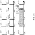
- FIG. 121 diagrammatically depicts a volume sensor assembly included within the infusion pump assembly of FIG. 1 ;
- FIG. 122 diagrammatically depicts an inter-connection of the various systems of the infusion pump assembly of FIG. 1 ;
- FIG. 126 A- 126 M depicts a hierarchal state machine
- FIG. 127 is an exemplary diagram of a split ring resonator antenna
- FIG. 133 A is a graph of the return loss of a non-split ring resonator antenna during contact with human skin;
- FIGS. 134 - 145 depict an embodiment of a charger, including various perspective views, exploded views, and partially exploded views;
- FIGS. 174 - 193 depict various views and aspects of an embodiment of a fill adapter
- FIGS. 194 - 198 depict various views and aspects of another embodiment of a fill adapter
- FIG. 202 A- 202 B are isometric views of the vial adapter according to one embodiment
- FIG. 206 B an isometric top view of one embodiment of the disposable housing assembly
- FIG. 207 A an isometric bottom view of one embodiment of the fill adapter
- FIG. 209 A is a top view of one embodiment of the fill adapter
- FIG. 210 A 1 is a top view of one embodiment of the fill adapter and disposable housing assembly in an attached and unlocked position
- FIG. 210 A is a cross sectional view of FIG. 210 A 1 taken at section “A”;
- FIG. 210 B is a cross sectional view of FIG. 210 B 1 taken at section “B”;
- FIG. 210 C 1 is a top view of one embodiment of the fill adapter and disposable housing assembly in an attached and unlocked position
- FIG. 210 C is a cross sectional view of FIG. 210 C 1 taken at section “C”;
- FIG. 211 A is an isometric exploded view of one embodiment of the fill adapter base and filling aid
- FIG. 211 B is an isometric top view of one embodiment of the of the fill adapter base and filling aid
- FIG. 211 C is an isometric top view of one embodiment of the fill adapter base and filling aid, rotated from the view shown in FIG. 211 B ;
- FIG. 212 A is an isometric top view of one embodiment of the fill adapter
- FIG. 212 B is an isometric top view of the embodiment of the fill adapter shown in FIG. 212 A in a partially folded position;
- FIG. 212 C is an isometric top view of the embodiment of the fill adapter shown in FIG. 212 A in a folded position;
- FIG. 213 A is an isometric top view of one embodiment of a disposable housing assembly without the top portion or membrane;
- FIG. 213 B is a magnified partial sectional view of FIG. 213 A taken at section “B”;
- FIG. 214 is a view of a fill adapter according to one embodiment
- FIG. 215 is a bottom view of a fill adapter according to one embodiment
- FIG. 216 is a view of a fill adapter with a filling syringe and a disposable housing assembly according to one embodiment
- FIG. 217 is an exploded view of one embodiment of a fill adapter
- FIG. 218 is a view of one embodiment of a fill adapter with a view of one embodiment of a filling needle cradle;
- FIG. 219 is a view of a filling syringe attached to a fill adapter according to one embodiment and a disposable housing assembly according to one embodiment;
- FIGS. 220 A- 220 F are cross sections views of one embodiment of a filling syringe and a fill adapter during the fill process according to one embodiment;
- FIG. 221 is a view of one embodiment of a fill adapter together with a one embodiment of a vial, a pusher and one embodiment of a disposable housing assembly;
- FIG. 222 A- 222 G are cross sections views of one embodiment of a vial, a pusher, a fill adapter and a disposable housing assembly during the fill process according to one embodiment;
- FIG. 223 is a view of one embodiment of the fill adapter together with one embodiment of the pusher, vial and disposable housing assembly;
- FIG. 224 is a view of one embodiment of the fill adapter together with one embodiment of the filling syringe and disposable housing assembly;
- FIG. 225 shows an embodiment of a fill adapter together connected to a disposable housing assembly, with a filling aid and filling syringe;
- FIG. 226 A is an underside exploded view of one embodiment of a fill adapter
- FIG. 226 B is a top view exploded view of one embodiment of a fill adapter
- FIG. 227 is a cross sectional view of one embodiment of a fill adapter
- FIG. 228 is a top view of one embodiment of a disposable housing assembly
- FIG. 229 is an isometric underside view of one embodiment of a fill adapter and one embodiment of a disposable housing assembly
- FIG. 230 is an isometric underside view of one embodiment of a fill adapter attached to one embodiment of a disposable housing assembly
- FIG. 231 A is an exploded view of one embodiment of a filling aid
- FIG. 231 B is an isometric view of one embodiment of a filling aid
- FIG. 231 C is a cross sectional view of one embodiment of a filling aid
- FIG. 232 A is an isometric view of one embodiment of a needle housing
- FIG. 232 B is a cross sectional view of one embodiment of a needle housing
- FIG. 233 A is an isometric view of one embodiment of a filling needle cradle
- FIG. 233 B is a cross sectional view of one embodiment of a filling needle cradle
- FIG. 233 C is a top view of one embodiment of a filling needle cradle
- FIG. 234 is an isometric view of a filling syringe attached to a filling aid, and a vial, according to one embodiment
- FIG. 235 A is a side view of a filling syringe attached to a filling aid and a vial, according to one embodiment
- FIG. 235 B is a cross sectional view of the view shown in FIG. 235 A ;
- FIG. 236 is an isometric view of a fill adapter attached to a disposable housing assembly, and a filling syringe attached to a filling aid, according to one embodiment
- FIGS. 237 - 240 B show cross sectional views and isometric views of one embodiment of a filling syringe, a filling aid and a fill adapter during the fill process of filling one embodiments of a disposable housing assembly, according to one embodiment;
- FIG. 241 A is one embodiment of a fill adapter together with an embodiment of a filling syringe and a filling aid;
- FIG. 241 B is an underside view of the embodiment shown in FIG. 241 A ;
- FIG. 242 A- 242 E are various views of a fill adapter, together with a filling syringe and a filling aid, according to one embodiment
- FIG. 243 A is a top exploded view of one embodiment of a fill adapter
- FIG. 243 B is a bottom exploded view of one embodiment of a fill adapter
- FIG. 244 A is an exploded view of one embodiment of a filling aid
- FIGS. 244 B- 244 C are isometric views of one embodiment of a filling aid
- FIG. 244 D are various views of one embodiment of a filling aid
- FIG. 244 E are various views of one embodiment of a needle housing
- FIG. 244 F are various views of one embodiment of a filling needle cradle
- FIG. 245 A is an isometric view of a filling syringe attached to a filling aid, also, a vial, according to one embodiment
- FIG. 245 B is an isometric view of a filling syringe attached to both a filling aid and the filling aid attached to a vial, according to one embodiment
- FIG. 246 is an isometric view of a fill adapter attached to a disposable housing assembly, and a filling syringe attached to a filling aid, according to one embodiment
- FIG. 247 is an isometric view of a fill adapter attached to a disposable housing assembly and to a filling aid, which is also attached to a filling syringe, according to one embodiment;
- FIG. 248 is an isometric view of one embodiment of a filling syringe, a filling aid and a fill adapter during the fill process of filling one embodiment of a disposable housing assembly, according to one embodiment;
- FIGS. 249 A- 249 B are isometric views of a filling aid according to one embodiment
- FIG. 249 C is an isometric view of a filling syringe holder according to one embodiment
- FIG. 249 D is an isometric view of a locking portion according to one embodiment
- FIG. 249 E is bottom view of a filling aid according to one embodiment
- FIG. 249 F is a cross sectional view of one embodiment of a filling aid taken at section “E” shown in FIG. 249 E ;
- FIG. 250 A is an isometric view of a filling syringe holder according to one embodiment
- FIG. 250 B is a bottom view of filling syringe holder according to one embodiment
- FIG. 251 B is a cross sectional view of one embodiment of a locking portion
- FIG. 253 A is an exploded view of a fill adapter and a disposable housing assembly according to one embodiment
- FIG. 254 B is an isometric view of a fill adapter attached to a disposable housing assembly and to a filling aid, in the locked and starting position, which is also attached to a filling syringe, according to one embodiment;
- FIG. 254 C is an isometric view of one embodiment of a filling syringe, a filling aid in the unlocked and filling position and a fill adapter during the fill process of filling one embodiment of a disposable housing assembly, according to one embodiment;
- FIGS. 258 - 272 show various views of one embodiment of a filling aid attached to one embodiment of a disposable housing assembly
- FIG. 273 is an enlarged partial view of a disposable housing assembly showing an over molded AVS assembly
- an infusion pump assembly 100 may include a reusable housing assembly 102 .
- Reusable housing assembly 102 may be constructed from any suitable material, such as a hard or rigid plastic, that will resist compression.
- suitable material such as a hard or rigid plastic
- use of durable materials and parts may improve quality and reduce costs by providing a reusable portion that lasts longer and is more durable, providing greater protection to components disposed therein.
- Reusable housing assembly 102 may include mechanical control assembly 104 having a pump assembly 106 and at least one valve assembly 108 .
- Reusable housing assembly 102 may also include electrical control assembly 110 configured to provide one or more control signals to mechanical control assembly 104 and effectuate the basal and/or bolus delivery of an infusible fluid to a user.
- Disposable housing assembly 114 may include valve assembly 108 which may be configured to control the flow of the infusible fluid through a fluid path.
- Reusable housing assembly 102 may also include pump assembly 106 which may be configured to pump the infusible fluid from the fluid path to the user.
- Mechanical control assembly 104 may include at least one shape-memory actuator 112 .
- Pump assembly 106 and/or valve assembly 108 of mechanical control assembly 104 may be actuated by at least one shape-memory actuator, e.g., shape-memory actuator 112 , which may be a shape-memory wire in wire or spring configuration.
- Shape memory actuator 112 may be operably connected to and activated by electrical control assembly 110 , which may control the timing and the amount of heat and/or electrical energy used to actuate mechanical control assembly 104 .
- Shape memory actuator 112 may be, for example, a conductive shape-memory alloy wire that changes shape with temperature. The temperature of shape-memory actuator 112 may be changed with a heater, or more conveniently, by application of electrical energy.
- Shape memory actuator 112 may be a shape memory wire constructed of nickel/titanium alloy, such as NITINOLTM or FLEXINOL®.
- Infusion pump assembly 100 may be configured so that the volume measurements produced by volume sensor assembly 148 may be used to control, through a feedback loop, the amount of infusible fluid that is infused into the user.
- Cavity 116 may be at least partially formed by and integral to disposable housing assembly 114 .
- Cavity 116 may include a membrane assembly 124 for at least partially defining reservoir 118 .
- Reservoir 118 may be further defined by disposable housing assembly 114 , e.g., by a recess 126 formed in base portion 128 of disposable housing assembly 114 .
- membrane assembly 124 may be disposed over recess 126 and attached to base portion 128 , thereby forming reservoir 118 .
- Membrane assembly 124 may be attached to base portion 128 by conventional means, such as gluing, heat sealing, and/or compression fitting, such that a seal 130 is formed between membrane assembly 124 and base portion 128 .
- Membrane assembly 124 may be flexible and the space formed between membrane assembly 124 and recess 126 in base portion 128 may define reservoir 118 .
- Reservoir 118 may be non-pressurized and in fluid communication with a fluid path (not shown).
- Membrane assembly 124 may be at least partially collapsible and cavity 116 may include a vent assembly, thereby advantageously preventing the buildup of a vacuum in reservoir 118 as the infusible fluid is delivered from reservoir 118 to the fluid path.
- membrane assembly 124 is fully collapsible, thus allowing for the complete delivery of the infusible fluid.
- Cavity 116 may be configured to provide sufficient space to ensure there is always some air space even when reservoir 118 is filled with infusible fluid.
- membranes and reservoirs described herein may be made from materials including but not limited to silicone, NITRILE, and any other material having desired resilience and properties for functioning as described herein. Additionally, other structures could serve the same purpose.
- a partially collapsible non pressurized reservoir may advantageously prevent the buildup of air in the reservoir as the fluid in the reservoir is depleted. Air buildup in a vented reservoir could prevent fluid egress from the reservoir, especially if the system is tilted so that an air pocket intervenes between the fluid contained in the reservoir and the septum of the reservoir. Tilting of the system is expected during normal operation as a wearable device.
- Reservoir 118 may be conveniently sized to hold an insulin supply sufficient for delivery over one or more days.
- reservoir 118 may hold about 1.00 to 3.00 ml of insulin.
- a 3.00 ml insulin reservoir may correspond to approximately a three day supply for about 90% of potential users.
- reservoir 118 may be any size or shape and may be adapted to hold any amount of insulin or other infusible fluid.
- the size and shape of cavity 116 and reservoir 118 is related to the type of infusible fluid that cavity 116 and reservoir 118 are adapted to hold.
- Disposable housing assembly 114 may include a support member 132 ( FIG. 3 ) configured to prevent accidental compression of reservoir 118 . Compression of reservoir 118 may result in an unintentional dosage of infusible fluid being forced through the fluid path to the user.
- reusable housing assembly 102 and disposable housing assembly 114 may be constructed of a rigid material that is not easily compressible.
- support member 132 may be included within disposable housing assembly 114 to prevent compression of infusion pump assembly 100 and cavity 116 therein.
- Support member 132 may be a rigid projection from base portion 128 .
- support member 132 may be disposed within cavity 116 and may prevent compression of reservoir 118 .
- cavity 116 may be configured to provide sufficient space to ensure there is always some air space even when reservoir 118 is filled with infusible fluid. Accordingly, in the event that infusion pump assembly 100 is accidentally compressed, the infusible fluid may not be forced through cannula assembly 136 (e.g., shown in FIG. 9 ).
- Cavity 116 may include a septum assembly 146 ( FIG. 3 ) configured to allow reservoir 118 to be filled with the infusible fluid.
- Septum assembly 146 may be a conventional septum made from rubber or plastic and have a one-way fluid valve configured to allow a user to fill reservoir 118 from a syringe or other filling device.
- septum 146 may be located on the top of membrane assembly 124 .
- cavity 116 may include a support structure (e.g., support member 132 in FIG. 3 ) for supporting the area about the back side of the septum so as to maintain the integrity of the septum seal when a needle is introducing infusible fluid into cavity 116 .
- the support structure may be configured to support the septum while still allowing the introduction of the needle for introducing infusible fluid into cavity 116 .
- Infusion pump assembly 100 may include an overfill prevention assembly (not shown) that may e.g., protrude into cavity 116 and may e.g., prevent the overfilling of reservoir 118 .
- an overfill prevention assembly (not shown) that may e.g., protrude into cavity 116 and may e.g., prevent the overfilling of reservoir 118 .
- reservoir 118 may be configured to be filled a plurality of times.
- reservoir 118 may be refillable through septum assembly 146 .
- electronic control assembly 110 may monitor the fluid level of the infusible fluid in reservoir 118 . When the fluid level reaches a low point, electronic control assembly 110 may provide a signal, such as a light or a vibration, to the user that reservoir 118 needs to be refilled.
- a syringe, or other filling device may be used to fill reservoir 118 through septum 146 .
- Reservoir 118 may be configured to be filled a single time.
- a refill prevention assembly (not shown) may be utilized to prevent the refilling of reservoir 118 , such that disposable housing assembly 114 may only be used once.
- the refill prevention assembly (not shown) may be a mechanical device or an electro-mechanical device.
- insertion of a syringe into septum assembly 146 for filling reservoir 118 may trigger a shutter to close over septum 146 after a single filling, thus preventing future access to septum 146 .
- a sensor may indicate to electronic control assembly 110 that reservoir 118 has been filled once and may trigger a shutter to close over septum 146 after a single filling, thus preventing future access to septum 146 .
- Other means of preventing refilling may be utilized and are considered to be within the scope of this disclosure.
- disposable housing assembly 114 may include septum assembly 146 that may be configured to allow reservoir 118 to be filled with the infusible fluid.
- Septum assembly 146 may be a conventional septum made from rubber or any other material that may function as a septum, or, in other embodiments, septum assembly 146 may be, but is not limited to, a plastic, or other material, one-way fluid valve.
- septum assembly 146 is configured to allow a user to fill reservoir 118 from a syringe or other filling device.
- Disposable housing assembly 114 may include a septum access assembly that may be configured to limit the number of times that the user may refill reservoir 118 .
- septum access assembly 152 may include shutter assembly 154 that may be held in an “open” position by a tab assembly 156 that is configured to fit within a slot assembly 158 .
- shutter assembly 154 may be displaced downward, resulting in tab assembly 156 disengaging from slot assembly 158 .
- spring assembly 162 may displace shutter assembly 154 in the direction of arrow 164 , resulting in septum 146 no longer being accessible to the user.
- septum access assembly 166 is shown in the “open” position.
- septum access assembly 166 includes shutter assembly 168 and spring assembly 170 .
- septum access assembly 172 may include shutter assembly 174 and spring assembly 176 .
- shutter assembly 172 may move to the “closed” position (e.g., which may prevent further access of septum 146 by the user)
- tab 178 may at least partially engage slot 180 a .
- Engagement between tab 178 and slot 180 a may lock shutter assembly 172 in the “closed” position to inhibit tampering and reopening of shutter assembly 172 .
- Spring tab 182 of shutter assembly 172 may bias tab 178 into engagement with slot 180 a.
- septum access assemblies may not be actuated linearly.
- septum access assembly 184 that includes shutter assembly 186 that is configured to pivot about axis 188 .
- septum 146 When positioned in the open position (as shown in FIG. 7 A ), septum 146 may be accessible due to passage 190 (in shutter assembly 186 ) being aligned with passage 192 in e.g., a surface of disposable housing assembly 114 .
- passage 190 in shutter assembly 186
- passage 192 in e.g., a surface of disposable housing assembly 114 .
- septum access assemblies 166 , 172 upon penetrating septum 146 with filling syringe 160 (See FIG.
- shutter assembly 186 may be displaced in a clockwise fashion, resulting in passage 190 (in shutter assembly 186 ) no longer being aligned with passage 192 in e.g., a surface of disposable housing assembly 114 , thus preventing access to septum 146 .
- septum access assembly 194 includes shutter assembly 196 and spring assembly 198 that is configured to bias shutter assembly 196 in the direction of arrow 200 .
- Filling assembly 202 may be used to fill reservoir 118 .
- Filling assembly 202 may include shutter displacement assembly 204 that may be configured to displace shutter assembly 196 in the direction of arrow 206 , which in turn aligns passage 208 in shutter assembly 196 with septum 146 and passage 210 in septum access assembly 194 , thus allowing filling syringe assembly 212 to penetrate septum 146 and fill reservoir 118 .
- Infusion pump assembly 100 may include a sealing assembly 150 ( FIG. 3 ) configured to provide a seal between reusable housing assembly 102 and disposable housing assembly 114 .
- a sealing assembly 150 FIG. 3
- sealing assembly 150 may include an o-ring assembly (not shown).
- sealing assembly 150 may include an over molded seal assembly (not shown).
- sealing assembly 150 may be a watertight seal assembly and, thus, enable a user to wear infusion pump assembly 100 while swimming, bathing or exercising.
- infusion pump assembly 100 may include an external infusion set 134 configured to deliver the infusible fluid to a user.
- External infusion set 134 may be in fluid communication with cavity 118 , e.g. by way of the fluid path.
- External infusion set 134 may be disposed adjacent to infusion pump assembly 100 .
- external infusion set 134 may be configured for application remote from infusion pump assembly 100 , as discussed in greater detail below.
- External infusion set 134 may include a cannula assembly 136 , which may include a needle or a disposable cannula 138 , and tubing assembly 140 .
- Tubing assembly 140 may be in fluid communication with reservoir 118 , for example, by way of the fluid path, and with cannula assembly 138 for example, either directly or by way of a cannula interface 142 .
- External infusion set 134 may be a tethered infusion set, as discussed above regarding application remote from infusion pump assembly 100 .
- external infusion set 134 may be in fluid communication with infusion pump assembly 100 through tubing assembly 140 , which may be of any length desired by the user (e.g., 3-18 inches).
- tubing assembly 140 may be of any length desired by the user (e.g., 3-18 inches).
- infusion pump assembly 100 may be worn on the skin of a user with the use of adhesive patch 144
- the length of tubing assembly 140 may enable the user to alternatively wear infusion pump assembly 100 in a pocket. This may be beneficial to users whose skin is easily irritated by application of adhesive patch 144 .
- wearing and/or securing infusion pump assembly 100 in a pocket may be preferable for users engaged in physical activity.
- a hook and loop fastener system (e.g. such as hook and loop fastener systems offered by Velcro USA Inc. of Manchester, N.H.) may be utilized to allow for easy attachment/removal of an infusion pump assembly (e.g., infusion pump assembly 100 ) from the user.
- adhesive patch 144 may be attached to the skin of the user and may include an outward facing hook or loop surface.
- the lower surface of disposable housing assembly 114 may include a complementary hook or loop surface.
- the strength of the hook and loop connection may be stronger than the strength of the adhesive to skin connection. Accordingly, various hook and loop surface patterns may be utilized to regulate the strength of the hook and loop connection.
- FIGS. 10 A- 10 E five examples of such hook and loop surface patterns are shown. Assume for illustrative purposes that the entire lower surface of disposable housing assembly 114 is covered in a “loop” material. Accordingly, the strength of the hook and loop connection may be regulated by varying the pattern (i.e., amount) of the “hook” material present on the surface of adhesive patch 144 . Examples of such patterns may include but are not limited to: a singular outer circle 220 of “hook” material (as shown in FIG. 10 A ); a plurality of concentric circles 222 , 224 of “hook” material (as shown in FIG. 10 B ); a plurality of radial spokes 226 of “hook” material (as shown in FIG.
- infusion pump assembly 100 ′ may be configured via a remote control assembly 300 .
- infusion pump assembly 100 ′ may include telemetry circuitry (not shown) that allows for communication (e.g., wired or wireless) between infusion pump assembly 100 ′ and e.g., remote control assembly 300 , thus allowing remote control assembly 300 to remotely control infusion pump assembly 100 ′.
- Remote control assembly 300 (which may also include telemetry circuitry (not shown) and may be capable of communicating with infusion pump assembly 100 ′) may include display assembly 302 and input assembly 304 .
- Input assembly 304 may include slider assembly 306 and switch assemblies 308 , 310 .
- the input assembly may include a jog wheel, a plurality of switch assemblies, or the like.
- remote control assembly 300 may provide instructions to infusion pump assembly 100 ′ via wireless communication channel 312 established between remote control assembly 300 and infusion pump assembly 100 ′. Accordingly, the user may use remote control assembly 300 to program/configure infusion pump assembly 100 ′. Some or all of the communication between remote control assembly 300 and infusion pump assembly 100 ′ may be encrypted to provide an enhanced level of security.
- infusion pump assembly 100 , 100 ′ may include electrical control assembly 110 that may include one or more electrical components.
- electrical control assembly 110 may include a plurality of data processors (e.g. a supervisor processor and a command processor) and a radio processor for allowing infusion pump assembly 100 , 100 ′ to communicate with remote control assembly 300 .
- Each of these electrical components may be manufactured from a different component provider and, therefore, may utilize native (i.e. unique) communication commands. Accordingly, through the use of a standardized communication protocol, efficient communication between such disparate components may be accomplished.
- PCGP may also limit the number of messages in-flight from a given node, and may be coupled with a flow-control mechanism at the driver level to provide a deterministic approach to message delivery and may let individual nodes have different quantities of buffers without dropping packets. As a node runs out of buffers, drivers may provide back pressure to other nodes and prevent sending of new messages.
- PCGP may use a shared buffer pool strategy to minimize data copies, and may avoid mutual exclusions, which may have a small affect on the API used to send/receive messages to the application, and a larger affect on the drivers.
- PCGP may use a “Bridge” base class that provides routing and buffer ownership. The main PCGP class may be sub-classed from the bridge base class. Drivers may either be derived from a bridge class, or talk to or own a derived bridge class.
- PCGP may:
- Each software object may ask the buffer manager for the next buffer to use, and may then give that buffer to another object.
- Buffers may pass from one exclusive owner to another autonomicly, and queues may occur automatically by ordering buffers by sequence number.
- the buffer may be recycled (e.g., object attempts to give the buffer to itself, or frees it for the buffer manager to re-allocate later). Accordingly, data generally doesn't need to be copied, and routing simply writes over the buffer ownership byte.
- PCGP may provide various benefits, examples of which may include but are not limited to:
- the PCGP may build the packet quickly and may insert it into the buffer management system.
- a call to “packetProcessor” may apply protocol rules and may give the messages to the drivers/application.
- PCGP may:
- PCGP may work by doing all of the main work on one thread to avoid mutual exclusions, and to avoid doing considerable work on the send/reply or driver calls.
- the “packetProcessor” call may have to apply protocol rules to replies, new sent messages, and received messages. Reply messages may simply get routed, but new messages and received messages may have rules for routing the messages. In each case, the software may loop while a message of the right type is available to apply protocol rules until it cannot process the packets.
- Sending a new message may conform to the following rules:
- Receiving a message may conform to the following rules:
- PCGP may be configured such that:
- the communication system may have a limited number of buffers.
- drivers may stop receiving new packets and the application may be told that the application cannot send new packets.
- the application may try to perform one or more procedures, examples of which may include but are not limited to:
- the RX driver may be asked to receive a message from the other side of the interface.
- the RX driver may ask the buffer manager if there is an available buffer for storing a new message. The driver may then ask for a buffer pointer and may start filling the buffer with received data.
- the RX driver may call a function to route the packet. The route function may examine the destination byte in the packet header and may change the owner to either the other driver, or the application, or may detect that the packet is bad and may drop the packet by freeing the buffer.
- PCGP RX overhead may consist of asking for the next available buffer and calling the route function.
- code that performs such a function is as follows:
- a driver may perform a TX by asking the buffer manager for the pointer to the next buffer to send.
- the TX driver may then ask the other side of the interface if it can accept a packet. If the other side denies the packet, the TX driver may do nothing to the buffer, as its status has not changed. Otherwise, the driver may send the packet and may recycle/free the buffer.
- An example of code that performs such a function is as follows:
- asking for the nextBuffer may call the BufferManager::first(uint8 owner) function that may scan for buffers to free. Accordingly, full TX buffers with no hope of making a timeout may be freed on the thread that owns the buffer. A bridge that is doing TX (i.e., while looking for the next TX buffer) may free all of the TX buffers that are expired before receiving the next TX buffer for processing.
- buffers marked free may be transferred to the drivers to receive new packets, or to PCGP to receive new payloads for TX. Allocation from “free” may be done by the “packetProcessor” function. The number of sends and receives between “packetProcessor” calls may dictate how many LT_Driver_RX, GT_Driver_RX and PCGP_Free buffers need to be allocated.
- LT_Driver may represent drivers that handle addresses that are less than the node address.
- GT_Driver may represent drivers that handle addresses that are greater than the node address.
- the driver may put the data into an RX buffer that gets handed to the router.
- the router may then reassign the buffer to PCGP_Receive or to the other driver's TX (not shown). If the buffer contains obviously invalid data, the buffer may transition to free.
- the driver may discover the buffer is TX and may send the message. After sending the message, the buffer may immediately become an RX buffer if the driver was low in RX buffers, or the buffer may be freed for re-allocation.
- PCGP may process all buffers that the router marked as PCGP_Receive. At this point, data may be acted upon, so the CRC and other data items may be checked. If the data is corrupted, a statistic may be incremented and the buffer may be freed. Otherwise, the buffer may be marked as owned by the application. Buffers marked as owned by the application may be either recycled for the use of PCGP or freed for reallocation by the buffer manager.
- the application When the application wants to send a new message, it may be done in a re-entrant friendly/mutual exclusion manner. If the buffer may be allocated, PCGP may mark the buffer as busy. Once marked busy, no other thread calling the send or reply functions may grab this buffer, as it is owned by this function call's invocation. The remainder of the process of error checking and building the message may be done outside the isolated race condition mutual exclusion guarded code.
- the buffer may either transition to free or may become a valid filled CRC-checked buffer and passed to the router. These buffers may not be routed immediately and may be queued so that messages can be sent later (assuming that protocol rules allow).
- Reply messages may be marked differently than new send messages because reply messages may be routed with a higher priority than regular send messages and reply messages may have no rules limiting how many/when they can be sent.
- PCGP was designed to work with flow control, and flow control may negotiate the transfer of messages from one node to another node so that a buffer is never dropped because the other side of an interface lacks a buffer (which may cause back pressure on the sending node).
- Flow control may be apart of the shared buffer format.
- the first two bytes may be reserved for the driver so that the driver never needs to shift the packet bytes.
- Two bytes may be used so that one byte is the DMA length ⁇ 1, and the second byte is to control the flow of messages.
- These same two bytes may be synchronizing bytes if a PCGP message is transmitted over RS232.
- the packet When a packet is “in-flight”, the packet may be in the process of being sent by a driver on the way to its destination, being processed by the destination, or being sent back as a response.
- Typical delays are as follows:
- messages tend to complete the round trip either: quickly (e.g., ⁇ 50 ms); slowly (e.g., one or more seconds); or not at all.
- PCGP may use two different times (set at initialization) for all timeouts, one for when the RF link is in fast heartbeat mode, and another for when the RF link is in slow mode. If a message is in-flight and the link status changes from fast to slow, the timeout may be adjusted and the difference between fast and slow may be added to the time-to-live counter for the packet. No additional transitions back and forth may affect the time-to-live time for the message.
- the PCGP messaging system may pass messages that contain header information and payload.
- the header may be a set of data items in a call signature.
- Drivers may insert bytes either into the PCGP packet or before the PCGP packet such:
- PCGP may not be an event driven software design, but may be used in event driven architectures by how the sub-classes are written. Data may be exchanged between the classes conceptually (as shown in FIG. 11 M- 11 N ).
- Some event model in the driver may wake the driver, may receive a message and may pass the message through the bridge into the buffer manager that routes the message to new owner of the new message (through a bridge to either a driver or PCGP).
- the following illustrative example shows how the PCGP event model may work with Nucleus to wakeup the PCGP task after every message send, reply, or decTimeout that generated a NACK:
- class PcgpOS public Pcgp ⁇ virtual void schedulePacketProcessor(void) ⁇ OS_EventGrp_Set(g_RCVEvGrps[EVG_RF_TASK].pEvgHandle, RfRadioTxEvent, OS_EV_OR_NO_CLEAR); ⁇ ⁇
- PCGP PCGP
- PCGP may be designed to run in multiple processing environments. Most parameters may be run time configured because it facilitates testing, and any run time fine tuning for performance. Other parameters may be compile time e.g., anything that alters memory allocation must be done statically at compile time.
- the CRC may be used to ensure data integrity. If a CRC is invalid, it may not be delivered to the application and the CRC error may be tracked. The message may eventually timeout and may be retried by the originator.
- the Stop Bolus Command is an example of such a command. This may be mitigated by the Request/Action sequence of messages which may be required by the application to change therapy.
- the Controller may receive a matching command from the Pump application to consider the message delivered.
- DEKA may provide a reference way of interfacing PCGP into the Nucleus OS system on the ARM 9 (as shown in FIG. 110 ).
- the pcgpOS.cpp file may instantiate a PCGP node instance (Pcgp, a Bridge, etc.) and may provide through pcgpOS.h a ‘C’ linkable set of function calls that provide a ‘C’ language interface to the C++ code. This may simplify the ‘C’ code as the objects acted upon are implicit.
- SPI flow control may prevent data from being sent if the receiving side does not currently have an empty buffer to place the packet. This may be accomplished by asking for permission to send and waiting for a response indicating that you have been cleared to do so. There may also be a way to tell the other side that there are currently no free buffers and the transfer should be attempted at a later time.
- All transmission may begin with a length byte that indicates the number of bytes to be sent, not including the length byte itself. Following the length may be a single byte indicating the command being sent.
- the actual transmission of a packet may be the length of packet plus one for the command byte, followed by the command byte for a message appended and finally the packet itself.
- FlowControl line may be added to the traditional four SPI signals.
- the purpose of this line is to allow the protocol to run as quickly as possible without a need for preset delays. It also allows the slave processor to tell the master processor that it has a packet waiting to be sent, thus eliminating the need for the master processor to poll the slave processor for status.
- Commands to be sent by the master processor : Command Value Description M_RTS 0xC1 Master is requesting to send a packet M_MSG_APPENDED 0xC2 Master is sending a packet M_CTS 0xC3 Master is tell slave it is Cleared to Send M_ERROR 0xC4 An Error condition has been encountered
- Commands to be sent by the slave processor : Command Value Description S_PREPARING_FOR_RX 0xA1 Slave is prepare the dma to receive a packet S_RX_BUFF_FULL 0xA2 Slave is currently out of RX buffers, retry later S_MSG_APPENDED 0xA3 Slave is sending a packet S_ERROR 0xA4 An Error condition has been encountered
- the slave processor may notify the master processor (by asserting the FlowControl line) that it has a pending packet that is waiting to be sent. Doing so may result in an IRQ on the master processor at which time the master processor may decide when to go retrieve the message from the slave processor. Retrieving the packet may be delayed at the discretion of the master processor, and the master processor may even decide to attempt to send a packet to the slave processor before retrieving from the slave processor.
- the master processor may begin the retrieval by sending the slave processor M_CTS commands; this shall be repeated until the slave processor responds by sending the S_MSG_APPENDED command along with the packet itself.
- the FlowControl line may be cleared after the packet has been sent. If a M_CTS command is received by the slave processor when one is not expected, the M_CTS command may be ignored.
- the master processor may initiate the transfer by sending a M_RTS command.
- M_RTS command if the slave processor currently has a send packet pending, the slave processor will lower the FlowControl line so that it may be re-used as a Cleared To Send signal.
- the slave processor may then tell the master processor that it is in the process of preparing the SPI DMA to receive the packet, during which time the master processor may stop clocking bytes onto the bus and may allow the slave processor to finish preparing for the receive.
- the slave processor may then indicate it is ready to receive the full packet by raising the FlowControl line (which is now used as the CTS signal). Upon receiving the CTS signal, the master processor may proceed to send the M_MSG_APPENDED command along with the packet itself.
- the slave processor may lower the FlowControl line. If a packet was pending at the start of the transfer, or a send occurred on the slave processor when the packet was being received, the slave processor may reassert the FlowControl line now indicating that it has a pending packet.
- infusion pump assembly 100 , 100 ′ may include switch assembly 318 coupled to electrical control assembly 110 ( FIG. 3 ) that may allow a user (not shown) to perform at least one, and in some embodiments, a plurality of tasks.
- a user not shown
- One illustrative example of such a task is the administration of a bolus dose of the infusible fluid (e.g., insulin) without the use of a display assembly.
- Remote control assembly 300 may allow the user to enable/disable/configure infusion pump assembly 100 , 100 ′ to administer the bolus dose of insulin.
- slider assembly 306 may be configured, at least in part, to enable the user to manipulate the menu-based information rendered on display assembly 302 .
- An example of slider assembly 306 may include a capacitive slider assembly, which may be implemented using a CY8C21434-24LFXI PSOC offered by Cypress Semiconductor of San Jose, Calif., the design an operation of which are described within the “CSD User Module” published by Cypress Semiconductor.
- the user may slide their finger in the direction of arrow 314 , resulting in the highlighted portion of the information included within main menu 350 (shown in FIG. 12 A ) rendered on display assembly 302 scrolling upward.
- the user may slide their finger in the direction of arrow 316 , resulting in the highlighted portion of the information included within main menu 350 rendered on display assembly 302 scrolling downward.
- Slider assembly 306 may be configured so that the rate at which e.g. the highlighted portion of main menu 350 scrolls “upward” or “downward” varies depending upon the displacement of the finger of the user with respect to point of origin 320 . Therefore, if the user wishes to quickly scroll “upward”, the user may position their finger near the top of slider assembly 306 . Likewise, if the user wishes to quickly scroll “downward”, the user may position their finger near the bottom of slider assembly 306 . Additionally, if the user wishes to slowly scroll “upward”, the user may position their finger slightly “upward” with respect to point of origin 320 Further, if the user wishes to slowly scroll “downward”, the user may position their finger slightly “downward” with respect to point of origin 320 . Once the appropriate menu item is highlighted, the user may select the highlighted menu item via one or more switch assemblies 308 , 310 .
- infusion pump assembly 100 , 100 ′ is an insulin pump and the user wishes to configure infusion pump assembly 100 , 100 ′ so that when switch assembly 318 is depressed by the user, a 0.20 unit bolus dose of insulin is administered.
- the user may use slider assembly 306 to highlight “Bolus” within main menu 350 rendered on display assembly 302 .
- the user may then use switch assembly 308 to select “Bolus”.
- processing logic (not shown) within remote control assembly 300 may then render submenu 352 on display assembly 302 (as shown in FIG. 12 B ).
- the user may then use slider assembly 306 to highlight “Manual Bolus” within submenu 352 , which may be selected using switch assembly 308 .
- Processing logic (not shown) within remote control assembly 300 may then render submenu 354 on display assembly 302 (as shown in FIG. 12 C ).
- the user may then use slider assembly 306 to highlight “Bolus: 0.0 Units” within submenu 354 , which may be selected using switch assembly 308 .
- Processing logic (not shown) within remote control assembly 300 may then render submenu 356 on display assembly 302 (as shown in FIG. 12 D ).
- the user may then use slider assembly 306 to adjust the “Bolus” insulin amount to “0.20 units”, which may be selected using switch assembly 308 .
- Processing logic (not shown) within remote control assembly 300 may then render submenu 358 on display assembly 302 (as shown in FIG. 12 E ).
- the user 14 may then use slider assembly 306 to highlight “Confirm”, which may be selected using switch assembly 308 .
- Processing logic (not shown) within remote control assembly 300 may then generate the appropriate signals that may be sent to the above-described telemetry circuitry (not shown) included within remote control assembly 300 .
- the telemetry circuitry (not shown) included within the remote control assembly may then transmit, via wireless communication channel 312 established between remote control assembly 300 and infusion pump assembly 100 ′, the appropriate configuration commands to configure infusion pump assembly 100 ′ so that whenever switch assembly 318 is depressed by the user, a 0.20 unit bolus dose of insulin is administered.
- processing logic within remote control assembly 300 may once again render submenu 350 on display assembly 302 (as shown in FIG. 12 F ).
- the user may depress switch assembly 318 of infusion pump assembly 100 ′ to administer the above-described 0.20 unit bolus dose of insulin.
- the user may define a quantity of insulin to be administered each time that the user depresses switch assembly 318 . While this particular example specifies that a single depression of switch assembly 318 is equivalent to 0.20 units of insulin, this is for illustrative purposes only and is not intended to be a limitation of this disclosure, as other values (e.g. 1.00 units of insulin per depression) are equally applicable.
- the user wishes to administer a 2.00 unit bolus dose of insulin.
- the user may be required to press and hold switch assembly 318 for a defined period of time (e.g. five seconds), at which point infusion pump assembly 100 , 100 ′ may generate an audible signal indicating to the user that infusion pump assembly 100 , 100 ′ is ready to administer a bolus does of insulin via switch assembly 318 .
- the user may depress switch assembly 318 ten times (i.e., 2.00 units is ten 0.20 unit doses).
- infusion pump assembly 100 , 100 ′ may provide on audible response to the user via an internal speaker/sound generation device (not shown). Accordingly, the user may depress switch assembly 318 the first time and infusion pump assembly 100 , 100 ′ may generate a confirmation beep in response, thus indicating to the user that infusion pump assembly 100 , 100 ′ received the command for (in this particular example) 0.20 units of insulin. As the desired bolus dose is 2.00 units of insulin, the user may repeat this procedure nine more times in order to effectuate a bolus dose of 2.00 units, wherein infusion pump assembly 100 , 100 ′ generates a confirmation beep after each depression of switch assembly 318 .
- infusion pump assemblies 100 , 100 ′ are described as providing one beep after each time the user depresses switch assembly 318 , this is for illustrative purposes only and is not intended to be a limitation of this disclosure.
- infusion pump assembly 100 , 100 ′ may be configured to provide a single beep for each defined quantity of insulin.
- a single depression of switch assembly 318 may be equivalent to 0.20 units of insulin.
- infusion pump assembly 100 , 100 ′ may be configured to provide a single beep for each 0.10 units of insulin.
- infusion pump assembly 100 , 100 ′ may provide the user with two beeps (i.e. one for each 0.10 units of insulin).
- infusion pump assembly 100 , 100 ′ may simply wait for infusion pump assembly 100 , 100 ′ to acknowledge receipt of the instructions to administer a 2.00 unit bolus dose of insulin (as opposed to the confirmation beep received at each depression of switch assembly 318 ). Once a defined period of time (e.g., two seconds) passes, infusion pump assembly 100 , 100 ′ may provide an audible confirmation to the user concerning the quantity of units to be administered via the bolus insulin dose that the user just requested.
- a defined period of time e.g., two seconds
- infusion pump assembly 100 , 100 ′ was programmed by the user so that a single depression of switch assembly 318 is equivalent to 0.20 units of insulin, infusion pump assembly 100 , 100 ′ may beep ten times (i.e., 2.00 units is ten 0.20 unit doses).
- infusion pump assembly 100 , 100 ′ may provide a multifrequency audible confirmation. For example and continuing with the above-stated example in which ten beeps are to be provided to the user, infusion pump assembly 100 , 100 ′ may group the beeps into groups of five (to facilitate easier counting by the user) and the beeps within each group of five may be rendered by infusion pump assembly 100 , 100 ′ so that each subsequent beep has a higher frequency than the preceding beep (in a manner similar to a musical scale).
- infusion pump assembly 100 , 100 ′ may render a 1,000 Hz beep, followed by an 1,100 Hz beep, followed by a 1,200 Hz beep, followed by a 1,300 Hz beep, followed by a 1,400 Hz beep (thus completing a group of five beeps), followed by a short pause, and then a 1,000 Hz beep, followed by an 1,100 Hz beep, followed by a 1,200 Hz beep, followed by a 1,300 Hz beep, followed by a 1,400 Hz beep (thus completing the second group of five beeps).
- the multifrequency audible confirmation may utilize various numbers of tones incrementing in frequency.
- an embodiment may utilize twenty different tones incrementing in frequency.
- the number of tones should not be construed as a limitation of the present disclosure as number of tones may vary according to design criteria and user need.
- infusion pump assembly 100 , 100 ′ completes the rendering of the multifrequency audible confirmation (i.e. the ten beeps described above), the user may, within a defined period of time (e.g. two seconds), depress switch assembly 318 to provide a confirmation signal to infusion pump assembly 100 , 100 ′, indicating that the multifrequency audible confirmation was accurate and indicative of the size of the bolus dose of insulin to be administered (i.e. 2.00 units).
- infusion pump assembly 100 , 100 ′ may render a “confirmation received” audible tone and effectuate the delivery of (in this particular example) the 2.00 unit bolus dose of insulin.
- infusion pump assembly 100 ′ and remote control assembly 300 may sound a “separation” alarm.
- the assembly that is unable to establish communication may sound a “separation” alarm.
- remote control assembly 300 is left in the car of the user, while infusion pump assembly 100 ′ is in the pocket of the user. Accordingly and after a defined period of time, infusion pump assembly 100 ′ may begin sounding the “separation” alarm, indicating that communication with remote control assembly 300 cannot be established.
- switch assembly 318 the user may acknowledge/silence this “separation” alarm.
- infusion pump assembly 100 ′ may store information concerning the administered bolus insulin dose within a log file (not shown) stored within infusion pump assembly 100 ′. This log file (not shown) may be stored within nonvolatile memory (not shown) included within infusion pump assembly 100 ′.
- infusion pump assembly 100 ′ may provide the information concerning the administered bolus insulin dose stored within the log file (not shown) of infusion pump assembly 100 ′ to remote control assembly 300 .
- infusion pump assembly 100 ′ and remote control assembly 300 may configure infusion pump assembly 100 ′ and remote control assembly 300 to be in “airplane” mode, in which each of infusion pump assembly 100 ′ and remote control assembly 300 suspend any and all data transmissions. While in “airplane” mode, infusion pump assembly 100 ′ and remote control assembly 300 may or may not continue to receive data.
- Switch assembly 318 may be used to perform additional functions, such as: checking the battery life of reusable housing assembly 102 ; pairing reusable housing assembly 102 with remote control assembly 300 ; and aborting the administration of a bolus does of infusible fluid.
- Reusable housing assembly 102 may include a rechargeable battery assembly that may be capable of powering infusion pump assembly 100 , 100 ′ for approximately three days (when fully charged). Such a rechargeable battery assembly may have a usable life of a predetermined number of usable hours, for example, or years, or other predetermined length of usage. However, the predetermined life may depend on many factors, including but not limited to, one or more of the following: climate, daily usage, and number of recharges. Whenever reusable housing assembly 102 is disconnected from disposable housing assembly 114 , infusion pump assembly 100 , 100 ′ may perform a battery check on the above-described rechargeable battery assembly whenever switch assembly 318 is depressed for a defined period of time (e.g. in excess of two seconds).
- a defined period of time e.g. in excess of two seconds.
- infusion pump assembly 100 ′ may be used to communicate with remote control assembly 300 .
- a paring process may be performed.
- one or more infusion pump assemblies e.g. infusion pump assembly 100 ′
- remote control assembly 300 may be configured to communicate with one or more infusion pump assemblies (e.g. infusion pump assembly 100 ′).
- the serial numbers of the infusion pump assemblies e.g.
- infusion pump assembly 100 ′ may be recorded within a pairing file (not shown) included within remote control assembly 300 and the serial number of remote control assembly 300 may be recorded within a pairing file (not shown) included within the infusion pump assemblies (e.g. infusion pump assembly 100 ′).
- the user may simultaneously hold down one or more switch assemblies on both remote control assembly 300 and infusion pump assembly 100 ′.
- the user may simultaneously hold down switch assembly 310 included within remote control assembly 300 and switch assembly 318 included within infusion pump assembly 100 ′ for a defined period exceeding e.g. five seconds. Once this defined period is reached, one or more of remote control assembly 300 and infusion pump assembly 100 ′ may generate an audible signal indicating that the above-described pairing procedure has been effectuated.
- the user may uncouple reusable housing assembly 102 from disposable housing assembly 114 .
- the user may uncouple reusable housing assembly 102 from disposable housing assembly 114 .
- the user may enter pairing mode via input assembly 304 of remote control assembly 300 .
- the user may enter pairing mode on remote control assembly 300 via the above-described menuing system in combination with e.g., switch assembly 310 .
- the user may be prompted on display assembly 302 of remote control assembly 300 to depress and hold switch assembly 318 on infusion pump assembly 100 ′.
- remote control assembly 304 may switch to a low power mode to e.g., avoid trying to pair with distant infusion pump assemblies.
- the user may then depress and hold switch assembly 318 on infusion pump assembly 100 ′ so that infusion pump assembly 100 ′ enters a receive mode and waits for a pairing command from remote control assembly 300 .
- Remote control assembly 300 may then transmit a pairing request to infusion pump assembly 100 ′, which may be acknowledged by infusion pump assembly 100 ′.
- Infusion pump assembly 100 ′ may perform a security check on the pairing request received from remote control assembly 300 and (if the security check passes) infusion pump assembly 100 ′ may activate a pump pairing signal (i.e., enter active pairing mode).
- Remote control assembly 300 may perform a security check on the acknowledgment received from infusion pump assembly 100 ′.
- the acknowledgment received from infusion pump assembly 100 ′ may define the serial number of infusion pump assembly 100 ′ and remote control assembly 300 may display that serial number on display assembly 302 of remote control assembly 300 .
- the user may be asked if they wish to pair with the pump found. If the user declines, the pairing process may be aborted. If the user agrees to the pairing process, remote control assembly 300 may prompt the user (via display assembly 302 ) to depress and hold switch assembly 318 on infusion pump assembly 100 ′.
- the user may then depress and hold switch assembly 318 on infusion pump assembly 100 ′ and depress and hold e.g. switch assembly 310 on remote control assembly 300 .
- Remote control assembly 300 may confirm that remote switch assembly 310 was held (which may be reported to infusion pump assembly 100 ′). Infusion pump assembly 100 ′ may perform a security check on the confirmation received from remote control assembly 300 to confirm the integrity of same. If the integrity of the confirmation received is not verified, the pairing process is aborted. If the integrity of the confirmation received is verified, any existing remote pair configuration file is overwritten to reflect newly-paired remote control assembly 300 , the pump pairing completed signal is activated, and the pairing process is completed.
- infusion pump assembly 100 ′ may confirm that switch assembly 318 was held (which may be reported to remote control assembly 300 ).
- Remote control assembly 300 may perform a security check on the confirmation received from infusion pump assembly 100 ′ to confirm the integrity of same. If the integrity of the confirmation received is not verified, the pairing process is aborted. If the integrity of the confirmation received is verified, a pair list file within remote control assembly 300 may be modified to add infusion pump assembly 100 ′.
- remote control assembly 300 may be capable of pairing with multiple infusion pump assemblies, while infusion pump assembly 100 ′ may be capable of only pairing with a single remote control assembly. The pairing completed signal may be activated and the pairing process may be completed.
- one or more of remote control assembly 300 and infusion pump assembly 100 ′ may generate an audible signal indicating that the above-described pairing procedure has been successfully effectuated.
- infusion pump assembly 100 ′ may depress switch assembly 318 (e.g., shown in FIGS. 1 & 2 ) for a defined period exceeding e.g. five seconds. Once this defined period is reached, infusion pump assembly 100 ′ may render an audible signal indicating that the above-described cancellation procedure has been effectuated.
- switch assembly 318 is shown as being positioned on the top of infusion pump assembly 100 , 100 ′, this is for illustrative purposes only and is not intended to be a limitation of this disclosure, as other configurations are possible.
- switch assembly 318 may be positioned about the periphery of infusion pump assembly 100 , 100 ′.
- infusion pump assembly 400 may include reusable housing assembly 402 and disposable housing assembly 404 .
- reusable housing assembly 402 may include a mechanical control assembly (that includes at least one pump assembly and at least one valve assembly).
- Reusable housing assembly 402 may also include an electrical control assembly that is configured to provide control signals to the mechanical control assembly and effectuate the delivery of an infusible fluid to a user.
- the valve assembly may be configured to control the flow of the infusible fluid through a fluid path and the pump assembly may be configured to pump the infusible fluid from the fluid path to the user
- disposable housing assembly 404 may be configured for a single use or for use for a specified period of time, e.g., e.g., three days or any other amount of time. Disposable housing assembly 404 may be configured such that any components in infusion pump assembly 400 that come in contact with the infusible fluid are disposed on and/or within disposable housing assembly 404 .
- infusion pump assembly 400 may include switch assembly 406 positioned about the periphery of infusion pump assembly 400 .
- switch assembly 406 may be positioned along a radial edge of infusion pump assembly 400 , which may allow for easier use by a user.
- Switch assembly 406 may be covered with a waterproof membrane configured to prevent the infiltration of water into infusion pump assembly 400 .
- Reusable housing assembly 402 may include main body portion 408 (housing the above-described mechanical and electrical control assemblies) and locking ring assembly 410 that may be configured to rotate about main body portion 408 (in the direction of arrow 412 ).
- reusable housing assembly 402 may be configured to releasably engage disposable housing assembly 404 .
- Such releasable engagement may be accomplished by a screw-on, a twist-lock or a compression fit configuration, for example.
- the user of infusion pump assembly 400 may first properly position reusable housing assembly 402 with respect to disposable housing assembly 404 and may then rotate locking ring assembly 410 (in the direction of arrow 412 ) to releasably engage reusable housing assembly 402 with disposable housing assembly 404 .
- Locking ring assembly 410 may include a latching mechanism (not shown) that may prevent the rotation of locking ring assembly 410 until reusable housing assembly 402 and disposable housing assembly 404 are properly positioned with respect to each other.
- infusion pump assembly 500 may include reusable housing assembly 502 and disposable housing assembly 504 .
- reusable housing assembly 502 may include a mechanical control assembly (that includes at least one pump assembly and at least one valve assembly).
- Reusable housing assembly 502 may also include an electrical control assembly that is configured to provide control signals to the mechanical control assembly and effectuate the delivery of an infusible fluid to a user.
- the valve assembly may be configured to control the flow of the infusible fluid through a fluid path and the pump assembly may be configured to pump the infusible fluid from the fluid path to the user.
- disposable housing assembly 504 may be configured for a single use or for use for a specified period of time, e.g., e.g., three days or any other amount of time. Disposable housing assembly 504 may be configured such that any components in infusion pump assembly 500 that come in contact with the infusible fluid are disposed on and/or within disposable housing assembly 504 .
- infusion pump assembly 500 may include switch assembly 506 positioned about the periphery of infusion pump assembly 500 .
- switch assembly 506 may be positioned along a radial edge of infusion pump assembly 500 , which may allow for easier use by a user.
- Switch assembly 506 may be covered with a waterproof membrane and/or an o-ring or other sealing mechanism may be included on the stem 507 of the switch assembly 506 configured to prevent the infiltration of water into infusion pump assembly 500 .
- switch assembly 506 may include an overmolded rubber button, thus providing functionality as a waterproof seal without the use of a waterproof membrane or an o-ring.
- the overmolded rubber button may additionally be covered by a waterproof membrane and/or include an o-ring.
- Reusable housing assembly 502 may include main body portion 508 (housing the above-described mechanical and electrical control assemblies) and locking ring assembly 510 that may be configured to rotate about main body portion 508 (in the direction of arrow 512 ).
- reusable housing assembly 502 may be configured to releasably engage disposable housing assembly 504 .
- Such releasable engagement may be accomplished by a screw-on, a twist-lock or a compression fit configuration, for example.
- the user of infusion pump assembly 500 may first properly position reusable housing assembly 502 with respect to disposable housing assembly 504 and may then rotate locking ring assembly 510 (in the direction of arrow 512 ) to releasably engage reusable housing assembly 502 with disposable housing assembly 404 .
- locking ring assembly 510 included within infusion pump assembly 500 may be taller (i.e., as indicated by arrow 514 ) than locking ring assembly 410 , locking ring assembly 510 may include a passage 516 through which button 506 may pass. Accordingly, when assembling reusable housing assembly 502 , locking ring assembly 510 may be installed onto main body portion 508 (in the direction of arrow 518 ). Once locking ring assembly 510 is installed onto main body portion 508 , one or more locking tabs (not shown) may prevent locking ring assembly 510 from being removed from main body portion 508 . The portion of switch assembly 506 that protrudes through passage 516 may then be pressed into main body portion 508 (in the direction of arrow 520 ), thus completing the installation of switch assembly 506 .
- button 506 is shown in various locations on infusion pump assembly 500 , button 506 , in other embodiments, may be located anywhere desirable on infusion pump assembly 500 .
- vibration motor assembly 602 may utilize a pair of spring-biased terminals (one positive terminal and one negative terminal) that are configured to press against corresponding conductive pads on printed circuit board 600 when vibration motor assembly 602 is positioned on printed circuit board 600 .
- vibration motor assembly 602 is soldered directly to the printed circuit board.
- Vibration motor assembly 602 may be configured to provide a vibration-based signal to the user of infusion pump assembly 500 .
- vibration motor assembly 602 may vibrate infusion pump assembly 500 to provide a vibration-based signal to the user of infusion pump assembly 500 .
- Shape memory actuator anchor 604 may provide a mounting point for the above-described shape memory actuator (e.g. shape memory actuator 112 ).
- shape memory actuator 112 may be, for example, a conductive shape-memory alloy wire that changes shape with temperature. The temperature of shape-memory actuator 112 may be changed with a heater, or more conveniently, by application of electrical energy.
- shape memory actuator 112 may be rigidly affixed (i.e., anchored) to shape memory actuator anchor 604 and the other end of shape memory actuator 112 may be applied to e.g. a valve assembly and/or a pump actuator. Therefore, by applying electrical energy to shape memory actuator 112 , the length of shape memory actuator 112 may be controlled and, therefore, the valve assembly and/or the pump actuator to which it is attached may be manipulated.
- the infusible fluid may be stored within reservoir 118 .
- the processing logic included within infusion pump assembly 500 may energize shape memory actuator 112 , which may be anchored on one end using shape memory actuator anchor 604 .
- shape memory actuator 112 may result in the activation of pump assembly 106 and reservoir valve assembly 614 .
- Reservoir valve assembly 614 may include reservoir valve actuator 614 A and reservoir valve 614 B, and the activation of reservoir valve assembly 614 may result in the downward displacement of reservoir valve actuator 614 A and the closing of reservoir valve 614 B, resulting in the effective isolation of reservoir 118 .
- pump assembly 106 may include pump plunger 106 A and pump chamber 106 B and the activation of pump assembly 106 may result in pump plunger 106 A being displaced in a downward fashion into pump chamber 106 B and the displacement of the infusible fluid (in the direction of arrow 616 ).
- Volume sensor valve assembly 612 may include volume sensor valve actuator 612 A and volume sensor valve 612 B. Referring also to FIG. 22 B , volume sensor valve actuator 612 A may be closed via a spring assembly that provides mechanical force to seal volume sensor valve 612 B. However, when pump assembly 106 is activated, if the displaced infusible fluid is of sufficient pressure to overcome the mechanical sealing force of volume sensor valve assembly 612 , the displacement of the infusible fluid occurs in the direction of arrow 618 . This may result in the filling of volume sensor chamber 620 included within volume sensor assembly 148 .
- volume sensor assembly 148 may determine the volume of infusible fluid included within volume sensor chamber 620 .
- Shape memory actuator 632 may be anchored (on a first end) to shape memory actuator anchor 636 . Additionally, the other end of shape memory actuator 632 may be used to provide mechanical energy to valve assembly 638 , which may activate measurement valve assembly 610 . Volume sensor assembly spring retainer 642 may properly position volume sensor assembly 148 with respect to the various other components of infusion pump assembly 500 . Valve assembly 638 may be used in conjunction with shape memory actuator 112 to activate pump plunger 106 A. Measurement valve 610 B, volume sensor valve 612 B and/or reservoir valve 614 B may be self-contained valves that are configured to allow for installation during assembly of infusion pump assembly 500 by pressing the valves upward into the lower surface of main body portion 508 .
- Pump actuator assembly 644 may include pump actuator support structure 646 , bias spring 648 , and lever assembly 650 .
- shape memory actuator 652 may be connected to a valve latch 656 .
- shape memory actuator 652 may pull valve latch 656 forward and release valve assembly 638 .
- measurement valve assembly 610 may be activated via shape memory actuator 632 .
- valve latch 656 may automatically latch valve assembly 638 in the activated position.
- Actuating shape memory actuator 652 may pull valve latch 656 forward and release valve assembly 638 .
- measurement valve assembly 610 may move to a de-activated state once valve latch 656 has released valve assembly 638 . Accordingly, through the use of measurement valve assembly 610 , shape memory actuator 632 does not need to be activated during the entire time that it takes to infuse the quantity of infusible fluid stored within volume sensor chamber 620 .
- peripheral tubing storage assembly 752 may include one or more divider portions 754 , 756 that form a plurality of narrower troughs that may be sized to generate an interference fit between the walls of the narrower trough and the exterior surface of the portion of tubing 140 .
- peripheral tubing storage assembly 752 includes plurality of divider portions 754 , 756 , the resulting narrower trough may be wound in a spiral fashion about the periphery of infusion pump assembly 750 (again, in a manner similar to the thread of a screw).
- Infusion pump assembly 750 may include tubing retainer assembly 758 .
- Tubing retainer assembly 758 may be configured to releasably secure tubing assembly 140 so as to prevent tubing assembly 140 from unraveling from around infusion pump assembly 750 .
- tubing retainer assembly 758 may include downward facing pin assembly 760 positioned above upward facing pin assembly 762 .
- the combination of pin assemblies 760 , 762 may define a “pinch point” through which tubing assembly 140 may be pushed. Accordingly, the user may wrap tubing assembly 140 around the periphery of infusion pump assembly 750 , wherein each loop of tubing assembly 140 is secured within peripheral tubing storage assembly 752 via tubing retainer assembly 758 .
- tubing retainer assembly 758 In the event that the user wishes to lengthen the unsecured portion of tubing assembly 140 , the user may release one loop of tubing assembly 140 from tubing retainer assembly 758 . Conversely, in the event that the user wishes to shorten the unsecured portion of tubing assembly 140 , the user may secure one additional loop of tubing assembly 140 within tubing retainer assembly 758 .
- infusion pump assembly 800 may include reusable housing assembly 802 and disposable housing assembly 804 .
- reusable housing assembly 802 may be configured to releasably engage disposable housing assembly 804 . Such releasable engagement may be effectuated by a screw-on, twist-lock, or compression fit configuration, for example.
- Infusion pump assembly 800 may include locking ring assembly 806 .
- reusable housing assembly 802 may be properly positioned relative to disposable housing assembly, and locking ring assembly 806 may be rotated to releasable engage reusable housing assembly 802 and disposable housing assembly 804 .
- Locking ring assembly 806 may include nub 808 that may facilitate rotation of locking ring assembly 806 . Additionally, the position of nub 808 , e.g., relative to tab 810 of disposable housing assembly 804 , may provide verification that reusable housing assembly 802 is fully engaged with disposable housing assembly 804 . For example, as shown in FIG. 34 A , when reusable housing assembly 802 is properly aligned with disposable housing assembly 804 , nub 808 may be aligned in a first position relative to tab 810 . Upon achieving a fully engaged condition, by rotation locking ring assembly 806 , nub 808 may be aligned in a second position relative to tab 810 , as shown in FIG. 34 B .
- reusable housing assembly 802 may include mechanical control assembly 812 (e.g., which may include valve assembly 814 , shown in FIG. 36 , including one or more valves and one or more pumps for pumping and controlling the flow of the infusible fluid).
- Reusable housing assembly 802 may also include an electrical control assembly 816 that may be configured to provide control signals to the mechanical control assembly 812 to effectuate the delivery of an infusible fluid to the user.
- Valve assembly 814 may be configured to control the flow of the infusible fluid through a fluid path and the pump assembly may be configured to pump the infusible fluid from the fluid path to the user.
- Mechanical control assembly 812 and electrical control assembly 816 may be contained within a housing defined by base plate 818 , body 820 .
- one or more of base plate 818 and body 820 may provide electromagnetic shielding.
- the electromagnetic shielding may prevent and/or reduce electromagnetic interference received by electrical control assembly 816 and/or created by electrical control assembly 816 .
- EMI shield 822 may be included, as shown in FIG. 36 and FIG. 37 . EMI shield 822 may provide shielding against generated and/or received electromagnetic interference.
- Reusable housing assembly 802 may include a switch assembly that may be configured to receive user commands (e.g., for bolus delivery, pairing with a remote control assembly, or the like).
- the switch assembly may include button 824 that may be disposed in opening 826 of body 820 .
- locking ring assembly 806 may include radial slot 828 that may be configured to allow locking ring assembly 806 to be rotated relative to body 820 while still providing facile access to button 824 .
- electrical control assembly 816 may include printed circuit board 830 as well as battery 832 .
- Printed circuit board 830 may include the various control electronics for monitoring and controlling the amount of infusible fluid that has been and/or is being pumped.
- electrical control assembly 816 may measure the amount of infusible fluid that has just been dispensed, and determine, based upon the dosage required by the user, whether enough infusible fluid has been dispensed. If not enough infusible fluid has been dispensed, electrical control assembly 816 may determine that more infusible fluid should be pumped.
- Electrical control assembly 816 may provide the appropriate signal to mechanical control assembly 812 so that any additional necessary dosage may be pumped or electrical control assembly 816 may provide the appropriate signal to mechanical control assembly 812 so that the additional dosage may be dispensed with the next dosage. Alternatively, if too much infusible fluid has been dispensed, electrical control assembly 816 may provide the appropriate signal to mechanical control assembly 812 so that less infusible fluid may be dispensed in the next dosage. Electrical control assembly 816 may include one or more microprocessors. In an exemplary embodiment, electrical control assembly 816 may include three microprocessors.
- One processor may be dedicated to radio communication, e.g., for communicating with a remote control assembly.
- Two additional microprocessors (example of which may include, but is not limited to an MSP430 microcontroller, available from Texas Instruments Inc. of Dallas, Tex.) may be dedicated to issuing and carrying out commands (e.g., to dispense a dosage of infusible fluid, process feedback signals from a volume measurement device, and the like).
- base plate 818 may provide access to electrical contacts 834 , e.g., which may be electrically coupled to electrical control assembly 816 for recharging battery 832 .
- Base plate 818 may include one or more features (e.g., openings 836 , 838 ) which may be configured to facilitate proper alignment with disposable housing assembly 804 by way of cooperating features (e.g., tabs) of disposable housing assembly 804 .
- base plate 818 may include various features for mounting valve assembly 814 and electrical control assembly 816 , as well as providing access to disposable housing assembly 804 by valve assembly 814 .
- Locking ring assembly 806 may include grip inserts 840 , 842 , e.g., which may include an elastomeric or textured material that may facilitate gripping and twisting locking ring assembly 806 , e.g., for engaging/disengaging reusable housing assembly 802 and disposable housing assembly 804 .
- locking ring assembly 806 may include a sensing component (e.g., magnet 844 ) that may interact with a component of reusable housing assembly 802 (e.g., a Hall Effect sensor), e.g., to provide an indication of the nature of a mating component (e.g., which in some embodiments may include, but is not limited to, one or more of disposable housing assembly 804 , a charging station, or a filling station) and/or of whether reusable housing assembly 802 is properly engaged with the mating component.
- a Hall Effect sensor (not shown) may be located on the pump printed circuit board. The Hall Effect sensor may detect when the locking ring has been rotated to a closed position. Thus, the Hall Effect sensor together with magnet 844 may provide a system for determining whether the locking ring has been rotated to a closed position.
- the sensing component (magnet) 844 together with the reusable housing assembly components may work to provide for a determination of whether the reusable housing assembly is properly attached to the intended component or device.
- Locking ring assembly 806 may not turn without being attached to a component, i.e., disposable housing assembly 804 , a dust cover or a charger.
- the sensing component together with the reusable housing assembly component may function to provide many advantageous safety features to the infusion pump system. These features may include, but are not limited to, one or more of the following.
- the system may notify, alert or alarm the user as the reusable portion, e.g., the valves and pumping components, may be vulnerable to contamination or destruction which may compromise the integrity of the reusable assembly.
- the system may provide for an integrity alarm to alert the user of potential reusable integrity threats.
- the system may power off or reduce power to conserve power. This may provide for more efficient use of power where the reusable assembly is not connecting to a component in which it needs to interact.
- Reusable housing assembly 802 may attach to a number of different components, including but not limited to, a disposable housing assembly, a dust cover or a battery charger/battery charging station.
- the Hall Effect sensor may detect that the locking ring is in the closed position, and therefore, that reusable housing assembly 802 is releasably engaged to a disposable housing assembly, a dust cover, or a battery charger/battery charging station (or, another component).
- the infusion pump system may determine the component to which it is attached by using the AVS system described in more detail below or by an electronic contact. Referring now also to FIGS. 38 B- 38 D , one embodiment of a dust cover (e.g., dust cover 839 ) is shown.
- dust cover 839 may include features 841 , 843 , 845 , 847 such that the locking ring of reusable housing assembly 802 may releasably engage dust cover 839 .
- dust cover 839 may further include recess region 849 for accommodating the valving and pumping features of reusable housing assembly 804 .
- the AVS system may determine that a dust cover, and not a disposable housing assembly, is connected to the reusable housing assembly. The AVS system may distinguish using a look-up table or other comparative data and comparing the measurement data with characteristic dust cover or empty disposable housing assembly data.
- the battery charger in the exemplary embodiments, may include electric contacts. When the reusable housing assembly is attached to the battery charger, the infusion pump assembly electronic system may sense that the contacts have been made, and will thus indicate that the reusable housing assembly is attached to a battery charger.
- valve assembly 814 which may include one or more valves and one or more pumps, is shown.
- valve assembly 814 may generally include reservoir valve 850 , plunger pump 852 , volume sensor valve 854 , and measurement valve 856 .
- reservoir valve 850 and plunger pump 852 may be actuated by shape memory actuator 858 , which may be anchored (on a first end) to shape memory actuator anchor 860 .
- measurement valve 856 may be actuated, via valve actuator 862 , by shape memory actuator 864 , which may be anchored (on a first end) to shape memory actuator anchor 866 .
- measurement valve may be maintained in an open position via measurement valve latch assembly 868 .
- Measurement valve 856 may be released via actuation of shape memory actuator 870 , which may be anchored (on a first end) by shape memory actuator anchor 872 .
- shape memory actuator anchor 860 may be potted onto the reusable housing assembly. Using this process during manufacture ensures shape memory length actuator 858 is installed and maintains the desired length and tension/strain.
- shape memory actuator 858 may actuate plunger pump 852 via actuator assembly 874 .
- Actuator assembly 874 may include bias spring 876 and lever assembly 878 .
- Actuator assembly 874 may actuate both plunger pump 852 and measurement valve 850 .
- measurement valve 856 may be actuated by shape memory actuator 864 , via valve actuator 862 and lever assembly 878 . Once actuated, measurement valve latch assembly 868 may maintain measurement valve 856 in an open position. Measurement valve latch assembly 868 actuated by shape memory actuator 870 to release measurement valve 856 , allowing it to return to a closed position.
- Disposable housing assembly 804 may be configured for a single use or for use for a specified period of time, e.g., e.g., three days or any other amount of time. Disposable housing assembly 804 may be configured such that any of the component of infusion pump assembly 800 that come in contact with the infusible fluid may be disposed on and/or within disposable housing assembly 804 . As such, the risk of contaminating the infusible fluid may be reduced.
- disposable housing assembly 804 may include base portion 900 , membrane assembly 902 , and top portion 904 .
- Base portion 900 may include recess 906 that together with membrane assembly 902 defines reservoir 908 for receiving an infusible fluid (not shown), e.g., insulin.
- recess 906 may be at least partially formed by and integral with base portion 900 .
- Membrane assembly 902 may be sealingly engaged with base portion 900 , e.g., by being compressively pinched between base portion 900 and top portion 904 .
- Top portion 904 may be attached to base portion 900 by conventional means, such as gluing, heat sealing, ultrasonic welding, and compression fitting. Additionally/alternatively, membrane assembly 902 may be attached to base portion 900 , e.g., via gluing, ultrasonic welding, heat sealing, and the like, to provide a seal between membrane assembly 902 and base portion 900 .
- recess 906 in the exemplary embodiment, includes raised portion 901 which includes area 903 about fluid openings 905 leading to the fluid line.
- Raised portion 901 in the exemplary embodiment, extends about the perimeter of recess 906 .
- raised portion 901 may not extend the entire perimeter, but may be partially about the perimeter.
- Area 903 about fluid openings 905 may be shaped as shown in the exemplary embodiment, including an angled portion, which in some embodiments, includes 45 degree angles, however in other embodiments, the angle may be greater or lesser.
- the pump may not generate a sufficient enough vacuum to collapse the reservoir so as to eliminate the entire volume of fluid that may be stored in the reservoir. Raised portion 901 may act to minimize wasted fluid.
- Fluid openings 905 which, in the exemplary embodiment, may include three openings, however, in other embodiments may include more openings or fewer openings, may be surrounded by area 903 of the raised portion.
- fluid openings 905 may be narrow in the center, thus creating a surface tension that may prevent the air from being drawn into the opening.
- this area may be designed to encourage any air that is present in the reservoir to be drawn above one of fluid openings 905 rather than be pulled through fluid openings 905 and into the fluid line. Additionally, because there may be more than one fluid opening 905 , where an air bubble is caught above one, the air may not prevent fluid from flowing through the other two openings.
- disposable housing assembly 804 may also include fluid pathway cover 910 .
- Fluid pathway cover 910 may be received in cavity 912 formed on/within base portion 900 .
- Fluid pathway cover 910 may, in some embodiments, include at least a portion of one or more channels (e.g., channel 914 ).
- the channels included in fluid pathway cover 910 may fluidly couple one or more volcano valve features (e.g. volcano valves 916 ) included on base portion 900 .
- Volcano valves 916 may include a protrusion having an opening extending through it.
- fluid pathway cover 910 and base portion 900 may each define a portion of recess (e.g., recess portions 918 , 920 included in base portion 900 and fluid pathway cover 910 respectively) for fluidly coupling to an infusion set (e.g., including cannula 922 ).
- Cannula 922 may be coupled to disposable housing assembly 804 by conventional means (e.g., gluing, heat sealing, compression fit, or the like).
- the fluid pathways defined by fluid pathway cover 910 and the volcano valves (e.g., volcano valves 916 ) of base portion 900 may define a fluid pathway between reservoir 908 and cannula 922 for the delivery of the infusible fluid to the user via the infusion set.
- fluid path cover 910 may include at least a portion of the fluid path, and in some embodiments, fluid path cover 910 may not include at least a portion of the fluid path.
- fluid pathway cover 910 may be laser welded to base portion 900 .
- fluid pathway cover 910 may also be connected to base portion 900 by conventional means (e.g., gluing, heat sealing, ultrasonic welding, compression fit, or the like) to achieve a generally fluid tight seal between fluid pathway cover 910 and base portion 900 .
- disposable housing assembly 804 may further include valve membrane cover 924 .
- Valve membrane cover 924 may be at least partially disposed over the volcano valves (e.g., volcano valve 916 ) and pumping recess 926 included on/within base portion 900 .
- Valve membrane cover 924 may include a flexible material, e.g., which may be selectively engaged against the volcano valves by reservoir valve 850 , volume sensor valve 854 , and measurement valve 856 of reusable housing assembly 802 , e.g., for controlling the flow of the infusible fluid.
- valve membrane cover 924 may be resiliently deformed into pumping recess 926 by plunger pump 852 to effectuate pumping of the infusible fluid.
- Valve membrane cover 924 may be engaged between base portion 900 and top portion 904 of disposable housing assembly 804 to form seal 928 between valve membrane cover 924 and base portion 900 .
- valve membrane cover 924 may be overmolded onto base portion 900 .
- valve membrane cover 924 may be compressively pinched between base portion 900 and top portion 904 to form seal 928 .
- valve membrane insert may be connected to one or more of base portion 900 and top portion 904 , e.g., by gluing, heat sealing, or the like.
- top portion 904 may include alignment tabs 930 , 932 that may be configured to be at least partially received in openings 836 , 838 of base plate 818 of reusable housing assembly 802 to ensure proper alignment between reusable housing assembly 802 and disposable housing assembly 804 . Additionally, top portion 904 may include one or more radial tabs 934 , 936 , 938 , 940 configured to be engaged by cooperating tabs 942 , 944 , 946 , 948 of locking ring assembly 806 .
- the one or more radial tabs may include stops (e.g., alignment tab stop 950 , which may be used for welding, it's the tab that fits in the recess to locate and ultrasonically weld), e.g., which may prevent further rotation of locking ring assembly 806 once reusable housing assembly 802 and disposable housing assembly 804 are fully engaged.
- stops e.g., alignment tab stop 950 , which may be used for welding, it's the tab that fits in the recess to locate and ultrasonically weld), e.g., which may prevent further rotation of locking ring assembly 806 once reusable housing assembly 802 and disposable housing assembly 804 are fully engaged.
- valve membrane insert 924 may allow for pumping and flow of the infusible fluid by reservoir valve 850 , plunger pump 852 , volume sensor valve 854 , and measurement valve 856 .
- top portion 904 may include one or more openings (e.g., openings 952 , 954 , 956 ) that may expose at least a portion of valve membrane insert 924 for actuation by reservoir valve 850 , plunger pump 852 , volume sensor valve 854 , and measurement valve 856 .
- top portion 904 may include one or more openings 958 , 960 , 962 which may be configured to allow the fill volume to be controlled during filling of reservoir 908 , as will be discussed in greater detail below.
- Reservoir assembly 902 may include ribs 964 , 966 , 968 (e.g., as shown in FIG. 52 A ), which may be at least partially received in respective openings 958 , 960 , 962 . As will be described in greater detail below, a force may be applied to one or more of ribs 964 , 966 , 968 to, at least temporarily, reduce the volume of reservoir 908 .
- disposable housing assembly 804 may include sealing assembly 970 .
- Sealing assembly 970 may include, for example, an elastomeric member that may provide a compressible rubber or plastic layer between reusable housing assembly 802 and disposable housing assembly 804 when engaged, thus preventing inadvertent disengagement and penetration by outside fluids.
- sealing assembly 970 may be a watertight seal assembly and, thus, enable a user to wear infusion pump assembly 800 while swimming, bathing or exercising.
- disposable housing assembly 802 may, in some embodiments, be configured to have reservoir 908 filled a plurality of times. However, in some embodiments, disposable housing assembly 114 may be configured such that reservoir 908 may not be refilled.
- fill adapter 1000 may be configured to be coupled to disposable housing assembly 804 for refilling reservoir 908 using a syringe (not shown).
- Fill adapter 1000 may include locking tabs 1002 , 1004 , 1006 , 1008 that may be configured to engage radial tabs 934 , 936 , 938 , 940 of disposable housing assembly 804 in a manner generally similar to tabs 942 , 944 , 946 , 948 of locking ring assembly 806 . Accordingly, fill adapter 1000 may be releasably engaged with disposable housing assembly 804 by aligning fill adapter 1000 with disposable housing assembly 804 and rotating fill adapter 1000 and disposable housing assembly 804 relative to one another to releasably engage locking tabs 1002 , 1004 , 1006 , 1008 with radial tabs 934 , 936 , 938 , 940 .
- Fill adapter 1000 may further include filling aid 1010 , which may include guide passage 1012 , e.g., which may be configured to guide a needle of a syringe (not shown) to a septum of disposable housing assembly 804 to allow reservoir 908 of disposable housing assembly 804 to be filled by the syringe.
- guide passage 1012 may be an angled bevel or other gradual angled bevel to further guide a syringe to a septum.
- Fill adapter 1000 may facilitate filling reservoir 908 by providing a relatively large insertion area, e.g., at the distal opening of guide passage 1012 .
- Guide passage 1012 may generally taper to a smaller proximal opening that may be properly aligned with the septum of disposable housing assembly 804 , when fill adapter 1000 is engaged with disposable housing assembly 804 . Accordingly, fill adapter 1000 may reduce the dexterity and aim necessary to properly insert a needle through the septum of disposable housing assembly 804 for the purpose of filling reservoir 908 .
- disposable housing assembly 804 may be configured to facilitate controlling the quantity of infusible fluid delivered to reservoir 908 during filling.
- membrane assembly 902 of disposable housing assembly 804 may include ribs 964 , 966 , 968 that may be depressed and at least partially displaced into reservoir 908 , thereby reducing the volume of reservoir 908 . Accordingly, when infusible fluid is delivered to reservoir 908 , the volume of fluid that may be accommodated by reservoir 908 may be correspondingly reduced. Ribs 964 , 966 , 968 may be accessible via openings 958 , 960 , 962 in top portion 904 of disposable housing assembly 804 .
- Fill adapter 1000 may include one or more button assemblies (e.g., button assemblies 1014 , 1016 , 1018 ) corresponding to ribs 964 , 966 , 968 . That is, when fill adapter 1000 is releasably engaged with disposable housing assembly 804 , buttons 1014 , 1016 , 1018 may be aligned with ribs 964 , 966 , 968 .
- Button assemblies 1014 , 1016 , 1018 may be, for example, cantilever members capable of being depressed.
- button assemblies 1014 , 1016 , 1018 When fill adapter 1000 is releasably engaged with disposable housing assembly 804 , one or more of button assemblies 1014 , 1016 , 1018 may be depressed, and may correspondingly displace a respective one of ribs 964 , 966 , 698 into reservoir 908 , causing an attendant reduction in the volume of reservoir 908 .
- reservoir 908 has a maximum capacity of 3.00 mL.
- button assembly 1014 is configured to displace rib 964 into disposable housing assembly 804 , resulting in a 0.5 mL reduction in the 3.00 mL capacity of disposable housing assembly 804 .
- button assembly 1016 is configured to displace rib 966 into disposable housing assembly 804 , also resulting in a 0.5 mL reduction in the 3.00 mL capacity of disposable housing assembly 804 .
- button assembly 1018 is configured to displace slot assembly 968 into disposable housing assembly 804 , also resulting in a 0.5 mL reduction in the 3.00 mL capacity of disposable housing assembly 804 .
- the user may first fill the reservoir to the 3.00 mL capacity and then depresses button assemblies 1016 and 1014 (resulting in the displacement of rib 966 into disposable housing assembly 804 ), effectively reducing the 3.00 mL capacity of reservoir 908 within disposable housing assembly 804 to 2.00 mL.
- the user may first depress a respective number of button assemblies, effectively reducing the capacity of reservoir 908 , and then fill reservoir 908 .
- the number of button assemblies may vary from a minimum of 1 to as many as is desired.
- each button assembly may displace 0.5 mL
- the volume of displacement per button may vary.
- the reservoir may be, in various embodiments, include a larger or smaller volume than described in the exemplary embodiment.
- the button assemblies may be employed, at least in part, to control the fill volume of reservoir 908 .
- the greatest fill volume of reservoir 908 may be achieved.
- Depressing one button assembly e.g., button assembly 1014
- Depressing two button assemblies e.g., button assemblies 1014 , 1016
- Depressing all three button assemblies e.g., button assemblies 1014 , 1016 , 1018
- button assemblies 1014 , 1016 , 1018 may be utilized, at least in part, to facilitate filling of reservoir 908 .
- a filling needle e.g., which may be fluidly coupled to a vial of infusible fluid
- button assemblies 1014 , 1016 , 1018 may be depressed to pump at least a portion of any air that may be contained within reservoir into the vial of infusible fluid.
- Button assemblies 1014 , 1016 , 1018 may subsequently be released to allow infusible fluid to flow from the vial into reservoir 908 .
- one or more button assemblies may be depressed, thereby squeezing at least a portion of the infusible fluid from reservoir 908 (e.g., via a needle used to fill reservoir 908 and back into the vial of infusible fluid).
- the volume of infusible fluid contained within reservoir 908 may be controlled, e.g., depending upon how many button assemblies are depressed (e.g., which may control how much infusible fluid is squeezed back into the vial of infusible fluid).
- filling aid 1010 may be pivotally coupled to fill adapter base plate 1020 .
- filling aid 1010 may include pivot members 1022 , 1024 that may be configured to be received in pivot supports 1026 , 1028 , thereby allowing filling aid to pivot between an open position (e.g., as shown in FIGS. 57 - 61 ) and a closed position (e.g., as shown in FIGS. 63 - 64 ).
- the closed position may be suitable, e.g., for packaging fill adapter 1000 , storage of fill adapter 1000 , or the like.
- fill adapter 1000 may include support member 1030 .
- a user may pivot filling aid 1010 to a fully open position, wherein filling aid 1010 may contact support member 1030 .
- fill adapter 1050 may be configured to releasably engage disposable housing assembly 804 via a plurality of locking tabs (e.g., locking tabs 1052 , 1054 ). Additionally, fill adapter 1050 may include a plurality of button assemblies (e.g., button assemblies 1056 , 1058 , 1060 ) that may interact with ribs 964 , 966 , 968 of disposable housing assembly 804 to adjust a fill volume of reservoir 908 .
- button assemblies e.g., button assemblies 1056 , 1058 , 1060
- Fill adapter 1050 may further include filling aid 1062 , having guide passage 1064 configured to align a needle of a syringe with the septum of disposable housing 804 , e.g., for accessing reservoir 908 for the purpose of filling reservoir 908 with an infusible fluid.
- Filling aid 1062 may be connected to base plate 1066 , e.g., as an integral component therewith, by gluing, heat sealing, compression fit, or the like.
- vial fill adapter 1100 may be configured to facilitate filling reservoir 908 of disposable housing assembly 804 directly from a vial. Similar to fill adapter 1000 , vial fill adapter 1100 may include locking tabs 1102 , 1104 , 1106 , 1108 that may be configured to engage radial tabs 934 , 936 , 938 , 940 of disposable housing assembly in a manner generally similar to tabs 942 , 944 , 946 , 948 of locking ring assembly 806 .
- vial fill adapter 1100 may be releasably engaged with disposable housing assembly 804 by aligning vial fill adapter 1100 with disposable housing assembly 804 and rotating vial fill adapter 1100 and disposable housing assembly 804 relative to one another to releasably engage locking tabs 1102 , 1104 , 1106 , 1108 with radial tabs 934 , 936 , 938 , 940 .
- disposable housing assembly 804 may be configured to facilitate controlling the quantity of infusible fluid delivered to reservoir 908 during filling.
- membrane assembly 902 of disposable housing assembly 804 may include ribs 964 , 966 , 968 that may be depressed and at least partially displaced into reservoir 908 , thereby reducing the volume of reservoir 908 . Accordingly, when infusible fluid is delivered to reservoir 908 , the volume of fluid that may be accommodated by reservoir 908 may be correspondingly reduced. Ribs 964 , 966 , 968 may be accessible via openings 958 , 960 , 962 in top portion 904 of disposable housing assembly 804 .
- Vial fill adapter 1100 may include one or more button assemblies (e.g., button assemblies 1110 , 1112 , 1114 ) corresponding to ribs 964 , 966 , 968 (e.g., shown in FIG. 52 A ). That is, when vial fill adapter 1100 is releasably engaged with disposable housing assembly 804 , buttons 1110 , 1112 , 1114 may be aligned with ribs 964 , 966 , 968 . Button assemblies 1110 , 1112 , 1114 may be, for example, cantilever members capable of being depressed.
- buttons assemblies 1110 , 1112 , 1114 may be depressed, and may correspondingly displace a respective one of ribs 964 , 966 , 698 into reservoir 908 , thereby reducing the volume of reservoir 908 .
- reservoir 908 has a maximum capacity of 3.00 mL.
- button assembly 1110 is configured to displace rib 964 into disposable housing assembly 804 , resulting in a 0.5 mL reduction in the 3.00 mL capacity of disposable housing assembly 804 .
- button assembly 1112 is configured to displace rib 966 into disposable housing assembly 804 , also resulting in a 0.5 mL reduction in the 3.00 mL capacity of disposable housing assembly 804 .
- button assembly 1114 is configured to displace rib 968 into disposable housing assembly 804 , also resulting in a 0.50 mL reduction in the 3.00 mL capacity of disposable housing assembly 804 .
- the user may depress button assemblies 1112 and 1114 (resulting in the displacement of ribs 966 and 968 into disposable housing assembly 804 ), effectively reducing the 3.00 mL capacity of reservoir 908 within disposable housing assembly 804 to 2.0 mL.
- Vial fill adapter 1100 may further include vial filling aid assembly 1116 that may be configured to fluidly couple a vial of infusible fluid to reservoir 908 of disposable housing assembly 804 via a septum.
- vial filling aid assembly may include double ended needle assembly 1118 .
- Double ended needle assembly 1118 may include first needle end 1120 configured to penetrate the septum of a vial (not shown) and second needle end 1122 configured to penetrate the septum of disposable housing assembly 804 .
- the vial and reservoir 908 may be fluidly coupled allowing infusible fluid to be transferred from the vial to reservoir 908 .
- Double ended needle assembly 1118 may include vial engagement portion 1124 adjacent first end 1120 .
- Vial engagement arms 1124 , 1126 may be configured to releasably engage, e.g., a vial cap, to assist in maintaining the fluid connection between double ended needle assembly 1118 and the vial.
- double ended needle assembly 1118 may include body 1128 that may be slidably received in opening 1130 of vial filling aid body 1132 .
- Vial filling aid body 1132 may include stabilizer arms 1134 , 1136 , e.g., which may be configured to stabilize the vial during filling of disposable housing assembly 804 .
- the vial may be engaged with double ended needle assembly 1118 e.g., such that first end 1120 may penetrate the septum of the vial and the cap of the vial may be engaged by engagement arms 1124 , 1126 .
- Body 1128 may be slidably inserted into opening 1130 such that second end 1122 of double ended needle assembly 1118 may penetrate the septum of disposable body assembly 804 .
- vial filling aid assembly 1116 may be configured to be pivotally coupled to vial fill adapter base plate 1138 .
- vial filling aid 1116 may include pivot members 1140 , 1142 that may be configured to be received in pivot supports 1144 , 1146 (e.g., shown in FIG. 71 ), thereby allowing vial filling aid 1116 to pivot between an open position (e.g., as shown in FIGS. 66 - 70 ) and a closed position (e.g., as shown in FIGS. 72 - 74 ).
- the closed position may be suitable, e.g., for packaging vial fill adapter 1100 , storage of vial fill adapter 1100 , or the like.
- vial fill adapter 1100 may include support member 1148 .
- a user may pivot vial filling aid 1116 to a fully open position, wherein vial filling aid 1116 may contact support member 1148 .
- vial fill adapter base plate 1138 may include one or more locking features (e.g., locking tabs 1150 , 1152 ) that may engage vial filing aid 1116 , and may maintain vial filling aid 1116 in the closed position.
- Vial fill adapter base plate 1138 may also include features (e.g., tabs 1154 , 1156 ) that may be configured to assist in retaining double ended needle assembly 1118 , e.g., by preventing slidable separation of double ended needle assembly 1118 from vial filling aid body 1132 .
- filling aid assembly 1116 is in a closed position.
- support member 1148 may additionally function as a needle guard.
- support member 1148 may function to safely allow a user to squeeze the ends and rotate filling aid assembly 1116 for removal.
- support member 1148 in the open position, support member 1148 may function as a stop to maintain proper orientation.
- the exemplary embodiments of the fill adapter include a grip feature (e.g., 1166 in FIG. 72 ).
- Grip feature 1166 may provide a grip interface for removal of the fill adapter from disposable housing assembly 804 .
- the configuration may vary.
- a grip feature may not be included.
- fill adapter base plate 1020 and vial fill adapter base plate 1138 may be interchangeable components. Accordingly, a single base plate (e.g., either fill adapter base plate 1020 or vial fill adapter base plate 1138 may be used with either filling aid 1010 or vial filling aid 1116 . Accordingly, the number of distinct components that are required for both filling adapters may be reduced, and a user may have the ability to select the filling adapter that may be the most suitable for a given filling scenario.
- the various embodiments of the fill adapters may provide many safety benefits, including but not limited to: providing a system for filling the reservoir without handling a needle; protecting the reservoir from unintentional contact with the needle, i.e., destruction of the integrity of the reservoir through unintentional puncture; designed to be ambidextrous; in some embodiments, may provide a system for maintaining air in the reservoir.
- the fill adapter may be configured to meter the fluid dispensed into the reservoir or the disposable housing assembly. Additionally/alternatively, the fill adapter may be configured to positively dispense (e.g., pump) the fluid into the reservoir of the disposable housing assembly.
- fill adapter 2700 may include a metering system for controlling the amount of fluid dispensed into the reservoir of the disposable housing assembly (e.g., reservoir 908 of disposable housing assembly 804 and a pumping mechanism for positively dispensing the fluid to reservoir 908 .
- fill adapter 2700 may include a turn dial (e.g., turn dial 2702 ) that may adjust the volume of fluid to be dispensed into reservoir 908 .
- turn dial 2702 may actuate push plate 2704 ( FIG. 181 ).
- Push plate 2704 may include one or more button features (e.g., button features 2706 , 2708 , 2710 shown in FIG. 187 , 188 ).
- Button features 2706 , 2708 , 2710 may displace one or more of ribs 964 , 966 , 968 associated with reservoir 908 , thereby reducing the available fill volume of reservoir 908 .
- the degree to which ribs 964 , 966 , 968 are displaced may determine the available fill volume of reservoir 908 (as discussed previously), and therefore also the volume of fluid that may be dispensed into reservoir 908 .
- Turn dial 2702 and push plate 2704 may include cooperating features that may enable turn dial 2702 to adjust the displacement of ribs 964 , 966 , 968 by push plate 2704 .
- turn dial 2702 and push plate 2704 may include cooperating ramp features, e.g., threads 2712 of push plate 2704 shown in FIG. 187 .
- Turn dial 2702 may include cooperating threads, such that when turn dial 2702 is turned in a first direction (e.g., clockwise) push plate 2704 may be linearly moved in a first direction to displace ribs 964 , 966 , 968 into reservoir 908 to decrease the available fill volume of reservoir 908 .
- push plate 2704 may be linearly moved in a second direction allowing ribs 964 , 966 , 968 to move to increase the available fill volume of reservoir 908 .
- ribs 964 , 966 , 968 may be utilized, including, but not limited to, cam features, rack and pinion features, etc.
- fill adapter 2700 may include one or more return features (such as springs, or other bias members; not shown) that may ensure that push plate 2704 is biased to increase the available fill volume of reservoir 908 in response to turn dial 2702 being adjusted from a smaller available fill volume to a larger available fill volume (e.g., as turn dial 2702 is turned in a counterclockwise direction in foregoing example).
- return features such as springs, or other bias members; not shown
- turn dial 2702 may be calibrated and turn dial 2702 and/or housing 2714 may include indicia that may indicate the available fill volume of reservoir 908 at a given rotational position of turn dial 2702 .
- turn dial 2702 may include a pointer and housing 2714 may include numerical indicia indicating available fill volume of reservoir 908 .
- the available fill volume of reservoir 908 may be the numerical value indicated by the cooperation of the pointer of turn dial 2702 and the numerical indicia of housing 2714 .
- fill adapter 2700 may be configured to positively dispense fluid into reservoir 908 .
- fill adapter 2700 may include a pump mechanism configured to pump air into a vial (e.g., vial 2716 shown in FIG. 181 ).
- a pump mechanism configured to pump air into a vial (e.g., vial 2716 shown in FIG. 181 ).
- pumping air into vial 2716 may pressurize vial 2716 to a pressure greater than a pressure within reservoir 908 .
- vial 2716 when vial 2716 is fluidly coupled with reservoir 908 , the greater pressure within vial 2716 may force fluid contained within vial 2716 into reservoir 908 .
- the volume of fluid transferred from vial 2716 into reservoir 908 may be controlled by turn dial 2702 and push plate 2704 (e.g., based upon, at least in part, the interaction between button features 2706 , 2708 , 2710 and fingers 964 , 966 , 968 ).
- the fill adapter may include a pump mechanism.
- fill adapter 2700 may include pump bulb 2718 , which may include a flexible convex member that may be biased toward a first volume, and compressible to a second volume that is less than the first volume.
- pump bulb 2718 may be compressed from the first volume to the second volume when pump bulb 2718 is pressed by a user's thumb or finger.
- a pumping volume e.g., the difference between the first volume and the second volume of pump bulb 2718
- turn dial 2702 may be controlled at least in part, by turn dial 2702 .
- the pumping volume may be controlled by turn dial 2702 to correspond to the available fill volume of reservoir 908 (e.g., the pumping volume may be a pumping volume of air that may result a transfer of a volume of fluid generally equal to the available fill volume of reservoir 908 ).
- pump bulb 2718 may include an inlet having an associated one-way valve that may allow air to enter pump bulb 2718 via the inlet when pump bulb 2718 expands from the second volume to the first volume, and may prevent air from exiting inlet when pump bulb 2718 is compressed from the first volume to the second volume.
- pump bulb 2718 may include an outlet having an associated one-way valve that may allow air to exit pump bulb 2718 via the outlet when pump bulb 2718 is compressed from the first volume to the second volume, and may prevent air from entering pump bulb 2718 via the outlet when pump bulb 2718 expands from the second volume to the first volume.
- Various valve mechanisms may be employed for the one-way inlet valve and the one-way outlet valve, including, but not limited to, ball valves, flap valves, diaphragm valves, and the like.
- the pump mechanism may include, but is not limited to, a piston pump, a diaphragm pump, or the like.
- pump bulb 2718 has been described as being compressed by a user's thumb or finger, various additional/alternative embodiments of a pump mechanism may be actuated by a turn crank, a lever, a pair of squeeze handles, a foot pump, and/or various other means of actuation.
- the outlet of pump bulb 2718 may be fluidly coupled to pressure needle 2720 ( FIG. 181 ).
- Pressure needle 2720 may be configured to penetrate a septum of vial 2716 .
- air may be transferred from pump bulb 2718 into vial 2716 .
- the transfer of air from pump bulb 2718 into vial 2716 may increase the internal pressure within vial 2716 .
- the one way valve associated with the outlet of pump bulb 2718 may prevent the retrograde flow of fluid from vial 2716 into pump bulb 2718 via pressure needle 2720 . Additionally, as schematically shown in FIG.
- hydrophobic filter 2722 may be associated with pressure needle 2720 .
- Hydrophobic filter 2722 may include any variety of gas-permeable hydrophobic materials, such as a POREXTM material, a GORETM material, or the like (POREX is a trademark of Porex Corporation in the United States and/or other countries, GORE is a trade mark of W. L. Gore & Associates, Inc. in the Unites States and/or other countries).
- Hydrophobic filter 2722 may allow the transmission of gaseous fluids (such as air), but may resist/prevent the passage of liquids (such as insulin or various other infusion fluids). Additionally, hydrophobic filter 2722 may have a restricted flow rate of gaseous fluids, and may, therefore, control the rate at which air can be pumped out of pump bulb 2718 and into vial 2716 .
- Fill adapter 2700 may further include a transfer needle (e.g., transfer needle 2724 shown in FIG. 181 ). Transfer needle 2724 may allow fluid to be transferred from vial 2716 to reservoir 908 of disposable housing assembly 804 . Referring also to FIG. 183 , in a “fill configuration” of fill adapter 2700 , transfer needle 2724 may extend into recess 2726 of fill adapter 2700 . Recess 2726 of fill adapter 2700 may be configured to at least partially receive disposable housing assembly 804 .
- a transfer needle e.g., transfer needle 2724 shown in FIG. 181 . Transfer needle 2724 may allow fluid to be transferred from vial 2716 to reservoir 908 of disposable housing assembly 804 . Referring also to FIG. 183 , in a “fill configuration” of fill adapter 2700 , transfer needle 2724 may extend into recess 2726 of fill adapter 2700 . Recess 2726 of fill adapter 2700 may be configured to at least partially receive disposable housing assembly 804 .
- fill adapter 2700 may be configured to align (e.g., via openings 2728 , 2730 configured to cooperate with alignment tabs 930 , 932 of disposable housing assembly 804 ) disposable housing assembly 804 relative to fill adapter 2700 , such that transfer needle 2724 may be aligned to penetrate a septum of disposable housing assembly 804 to transfer fluid from vial 2716 into reservoir 908 of disposable housing assembly 804 .
- pressure needle 2720 may be configured to extend farther into vial 2716 than transfer needle 2724 .
- the foregoing configuration may reduce the likelihood that air introduced into vial 2716 by pump bulb 2718 may be transferred via transfer needle 2724 . That is, in operation pressure needle 2720 may be at a higher relative position within vial 2716 as compared to transfer needle 2724 . As such, air bubble rising within vial 2716 (which may contain a liquid to be transferred to reservoir 908 ) may not pass by, and be drawn into, transfer needle 2724 , as transfer needle 2724 may be at a lower relative position within vial 2617 as compared to pressure needle.
- vial adapter 2732 may include vial receptacle 2734 that may be configured to at least partially receive vial 2716 and align pressure needle 2720 and transfer needle 2724 with the septum of vial 2716 . As such, insertion of vial 2716 into vial receptacle 2734 may align pressure needle 2720 and transfer needle 2724 with the septum of vial 2716 without the need for further alignment by the user. Further, vial adapter 2732 may retain pressure needle 2720 and transfer needle 2724 in a desired relative alignment, such that pressure needle 2720 may extend farther into vial 2716 than transfer needle 2724 , as described above.
- vial adapter 2732 may be configured to be received in receptacle 2736 of main plate 2738 of fill adapter 2700 (also see FIG. 181 ).
- Vial adapter 2732 may include needle carriage 2732 a as well as one or more tabs (e.g., tabs 2732 b , 2732 c ).
- vial 2716 may be removed from vial adapter 2732 by pulling up on vial 2716 . Pulling up on vial 2716 may also cause needle carriage 2732 a to move upwards until being engaged by the tabs 2732 b , 2732 c . Fingers 2733 a , 2733 b may be depressed by the user.
- depressing fingers 2733 a , 2733 b may push vial 2716 further upward, and may disconnect vial 2716 from needles 2720 , 2724 . As such, the safety of removing vial 2716 from vial adapter 2732 may be improved.
- vial adapter 2732 may additionally include seal 2735 a and hydrophobic filter 2735 b .
- the vial adapter 2732 may include a check valve.
- pressure needle 2720 may terminate within vial adapter 2732 , and may be fluidly coupled to opening 2740 of vial adapter 2732 .
- opening 2740 may be fluidly coupled with the outlet of pump bulb 2718 such that air pumped out of pump bulb 2718 may be received through opening 2740 and transferred to vial 2716 via pressure needle 2720 .
- a user couples the vial adapter 2732 to the main plate 2738 .
- the vial 2716 is then coupled to the vial adapter 2732 .
- the transfer needle 2724 penetrates the septum of the disposable housing assembly 804 (see 199 D) and also, the septum of the vial 2716 (see FIG. 199 E ).
- the transfer needle 2724 does not penetrate the septum of the vial 2716 until the transfer needle 2724 also penetrates the septum of the disposable housing assembly 804 . This ensures that if the vial 2716 is pressurized, the contents of the vial 2716 will not begin to flow until the transfer needle 2724 has penetrated the septum of the disposable housing assembly 804 , thereby limiting the amount of wasted vial contents.
- the user may couple disposable housing assembly 804 in recess 2726 of main plate 2738 (e.g., including aligning disposable housing assembly 804 relative to fill adapter 2700 via openings 2728 , 2730 configured to at least partially receive alignment tabs 930 , 932 of disposable housing assembly 804 ).
- Disposable housing assembly 804 may be retained relative to fill adapter 2700 using bottom door 2742 , which may pivotally close to at least partially cover recess 2726 to retain disposable housing assembly 804 at least partially within recess 2726 .
- a user may then couple the vial adapter 2732 to the main plate 2738 and then, couple a vial 2716 to the vial adapter 2732 .
- pump bulb 2718 may be configured such that a single complete actuation of pump bulb 2718 may be sufficient to effect a complete transfer (e.g., the volume of air transferred from pump bulb 2718 to vial 2716 during a single actuation of pump bulb 2718 may be sufficient to produce the transfer of the maximum fill volume of reservoir 908 ).
- fill adapter 2700 may be configured to overfill reservoir 908 (e.g., to transfer a volume of fluid from vial 2716 that is at least partially greater than the available fill volume of reservoir 908 , as determined by the settings of turn dial 2702 ). Overfilling reservoir 908 may allow the fluid passages associated with disposable housing assembly 804 to be primed with fluid, thereby obviating the need to later prime the fluid lines of disposable housing assembly 804 .
- the fill adapter 2700 includes vial fingers 2744 a , 2744 b .
- the vial 2716 overcomes the spring force of the vial fingers 2744 a , 2744 b .
- the vial fingers 2744 a , 2744 b return force and act to maintain the position of the vial 2716 .
- the vial adapter 2762 includes a needle carriage 2754 which includes vial needles 2756 a , 2756 b and transfer needle 2756 c .
- the needles 2756 a , 2756 b , 2756 c are 24 gauge stainless steel.
- the gauge of the needles may vary.
- the gauge of needle is a balance between flexibility and efficiency.
- the needle carriage 2754 is slidably engaged to the interior of the vial adapter housing 2752 .
- the vial adapter 2762 includes a check valve 2758 and a filter 2766 .
- the filter 2766 may be a 0.2 micron filter, or any other filter that prevents dust and other unwanted particulate matter, from entering the air line and the vial (not shown).
- the filter 2766 is a hydrophobic filter which may include any variety of gas-permeable hydrophobic materials, such as a POREXTM material, a GORETM material, or the like (POREX is a trademark of Porex Corporation in the United States and/or other countries, GORE is a trade mark of W. L. Gore & Associates, Inc.
- the check valve 2758 is a duck bill valve.
- the duck bill valve serves as a check valve and a seal.
- the check valve may be any type of check valve.
- the check valve is not included and only a hydrophobic filter is used.
- the hydrophobic filter my be as described above, and in these embodiments, a separate seal may also be used.
- the keys 2764 b fit into locking features 2764 a located inside the vial adapter housing 2752 . Once the keys 2764 b and locking features 2764 a are fit together, a clockwise turn of the vial adapter 2762 locks the vial adapter 2762 to the receptacle 2770 .
- the locking features 2764 a located inside the vial adapter housing 2752 may be designed such that a counterclockwise turn of the vial adapter 2762 locks the vial adapter 2762 to the receptacle 2770 .
- a user couples the vial adapter 2762 to the receptacle 2770 .
- the vial adapter 2762 is then rotated clockwise, locking the vial adapter 2762 to the receptacle 2770 (see FIG. 203 C ).
- the vial 2716 is then coupled to the vial adapter 2762 .
- the transfer needle 2756 c penetrates the septum of the disposable housing assembly 804 (see 203 E) and also, the septum of the vial 2716 (see FIG. 203 F ).
- the upward force first pulls the vial 2716 upwards such that the needles 2756 a , 2756 b are no longer in contact with the contents of the vial 2716 , rather, the needles 2756 a , 2756 b are inside the septum of the vial 2716 . This ensures that if the vial 2716 is pressurized, the contents of the vial 2716 will not continue to flow while the vial 2716 is being removed from the vial adapter 2756 thereby limiting the amount of wasted vial contents.
- the vial adapter 2762 additionally includes a disc 2774 (see also FIG. 200 ).
- the disc 2774 remains at the bottom of the vial adapter 2762 (which may also be referred to as the receptacle end of the vial adapter 2762 ) until the needle carriage 2754 reaches the bottom of the vial adapter 2762 .
- the needle carriage 2754 having reached the bottom of the vial adapter 2762 , the needle carriage 2754 is now connected to the disc 2774 .
- the disc 2774 includes features which mate with the needle carriage 2754 such that, when the needle carriage 2754 moves upward, or towards the top or vial end of the vial adapter 2762 , as seen in FIG. 203 H , the disc 2774 accompanies the needle carriage 2754 .
- FIGS. 204 A- 204 C a sequence showing the progression of the needle carriage 2754 and the relationship of the needle carriage 2754 with the disc 2774 is shown without a vial.
- the disc 2774 is locked in place by the wall features of the vial adapter 2762 .
- the vial adapter 2762 may be rotated counter clockwise ( FIG. 203 J ), unlocking the vial adapter 2762 from the receptacle 2770 , and the vial adapter 2762 may then be lifted off the fill adapter base 2768 ( FIG. 203 K ). Additionally, as is shown in FIG. 203 K , the needles 2756 a , 2756 b , 2756 c are contained within the vial adapter 2762 thus protecting the user and others from interaction with the needles 2756 a , 2756 b , 2756 c.
- Fill adapter 2800 may be generally similar to fill adapter 2700 , including a turn dial (e.g., turn dial 2802 ) that may actuate a push plate (e.g., push plate 2804 ) for setting an available fill volume of reservoir 908 of disposable housing assembly 804 ( FIGS. 197 - 198 ).
- Fill adapter 2800 may also include vial adapter 2806 configured to releasably couple a vial to fill adapter 2800 for transferring fluid from the vial to reservoir 908 of disposable housing assembly 804 .
- Fill adapter 2806 may include a pressure needle and/or a transfer needle respectively configured to introduce air into the vial and allow fluid to be transferred from the vial to reservoir 908 of disposable housing assembly 804 . While fill adapter 2800 is shown including recess 2808 and pivoting door 2810 for retaining disposable housing assembly to fill adapter 2800 , in other embodiments, the fill adapter may utilize locking features, e.g., which may releasably engage tabs 934 , 936 , 938 , 940 disposable housing assembly 804 .
- the vial adapter may be a one-use, i.e., disposable portion, and the fill adapter base may be a multi-use, i.e., reusable, portion.
- the needle carriage upon removal of the vial from the vial adapter, the needle carriage becomes locked in the end position. This may be desirable to prevent reuse and reuse may contaminate vials and disposable housing assemblies, for the transfer needle may become contaminated while stored between uses.
- Fill adapter 2800 may include actuation button 2812 , which may be disposed in turn dial 2802 .
- Actuation button 2812 may be configured as a plunger pump, e.g., which may pump air into the vial to effectuate fluid transfer from the vial into reservoir 908 , in a manner as described above.
- actuation button 2812 may operate a bias member (e.g., spring 2814 ) that may limit the amount of force that is transferred to reservoir 908 .
- spring 2814 may be disposed between actuation button 2812 and the pumping member that may actually pump air into the vial. As such, the force that may be transferred to reservoir 908 may be limited to the spring force of spring 2814 .
- the fill adapter 3000 may be configured to be coupled to an embodiment of the disposable housing assembly, including but not limited to, the disposable housing assembly 804 , shown and described above, or the disposable housing assembly 3002 , shown in FIG. 206 B .
- the embodiments of the disposable housing assembly 3002 shown in FIG. 206 B is similar to disposable housing assembly 804 .
- disposable housing assembly 3002 will be referred to with respect to fill aid adapter 3000 , however, in various other embodiments, the filling aid adapter 3000 may be coupled to any embodiment of the disposable housing assembly.
- the reservoir 908 may be filled using a syringe (not shown).
- a syringe any syringe known in the art may be used, however, in the exemplary embodiments, any syringe having a size and shape to be accommodated by the filling aid 3004 may be used, including, but not limited to, a 3 cc/mL TERUMO SYRINGE without needle, made by TERUMO Europe, Belgium, together with a Becton Dickinson 26G1/2 PRECISIONGLIDE Needle, made by Becton Dickinson & Co., Franklin Lakes, N.J., U.S.A., however, in various embodiments, the syringe may be a syringe and/or a syringe and filling needle and/or a filling needle made by another manufacture and/or at a larger or smaller size.
- Fill adapter 1000 may include locking tabs 3006 , 3008 , 3010 , 3012 that may be configured to engage radial tabs 3014 , 3016 , 3018 (and another, not shown) of disposable housing assembly 3002 in a manner generally similar to tabs 942 , 944 , 946 , 948 of locking ring assembly 806 . Accordingly, fill adapter 3000 may be releasably engaged with disposable housing assembly 3002 by aligning fill adapter 3000 with disposable housing assembly 3002 and rotating fill adapter 3000 and disposable housing assembly 3002 relative to one another to releasably engage locking tabs 3006 , 3008 , 3010 , 3012 with radial tabs 3014 , 3016 , 3018 (and another, not shown).
- the embodiment of the disposable housing assembly 3002 shown in FIG. 206 B includes an additional radial tab that is hidden in the view shown.
- the number of locking tabs and radial tabs may vary, for example, in various embodiments, the number of locking tabs or radial tabs may be greater than or less than the number shown in the exemplary embodiments.
- FIGS. 208 - 208 B the process for engaging the fill adapter 3000 with the disposable housing assembly 3002 is shown.
- FIG. 208 A shows the fill adapter 3000 attached to the disposable housing assembly 3002 and in the non-locked position.
- an indication of “lock” 3020 and “unlock” 3022 may be included on the disposable housing assembly, for example, as shown in the embodiment of the disposable housing assembly 3002 , for example, to indicate the direction of rotation 3024 to either “lock” 3020 or “unlock” 3022 the fill adapter 3000 , for example, and/or the locking ring assembly 806 , with respect to the disposable housing assembly 3002 .
- the indications 3020 , 3022 , 3024 may vary.
- the fill adapter 3000 having rotated with respect to the disposable housing assembly 3002 in the direction shown in FIG. 208 A , the direction of rotation 3024 also indicated on the disposable housing assembly 3002 , which is clockwise in the exemplary embodiment, the fill adapter 3000 is in the locked position with respect to the disposable housing assembly 3002 .
- the locked position (see FIG. 208 B ) is a position in which the fill adapter 3000 is coupled and/or engaged with the disposable housing assembly 3002 such that the fill adapter 3000 may not easily rotate with respect to the disposable housing assembly 3002 .
- the fill adapter 3000 may rotate counterclockwise from the locked position to the unlocked position following the exertion of force onto the locking tab actuator 3026 which releases the locking tab 3030 from the disposable housing assembly 3002 .
- filling aid base 3046 (which, in some embodiments is cylindrical and includes an opening to the cavity portion of the filling aid) is located opposite the locking tab actuator 3026 such that a user may release the locking tab 3030 using an ergonomically efficient configuration, e.g., placing the thumb on the filling aid base 3026 and the forefinger on the locking tab actuator 3025 to efficiently relay force on the locking tab actuator 3026 and release the locking tab 3030 .
- the fill adapter 3000 includes a rotation direction indication 3028 to indicate the direction of rotation to unlock the fill adapter 3000 from the disposable housing assembly 3002 .
- the fill adapter 3000 may be attached to the disposable housing assembly 3002 in the locked position. A user may fill the reservoir (which may be the embodiment as shown in FIG. 49 B, 908 ) of the disposable housing assembly 3002 using the fill adapter 3000 .
- the user may unlock the fill adapter 3000 by exerting force onto the locking tab actuator 3026 , which releases the locking tab 3030 , and rotating the fill adapter 3000 counterclockwise as indicated by the rotation direction indication 3028 on the fill adapter 3000 until the fill adapter 3000 is in the unlocked position, as shown in FIG. 208 A .
- the locking tab 3030 in the locked position, prevents counterclockwise rotation of the fill adapter 3000 with respect to the disposable housing assembly 3002 .
- the locking tab 3030 In the locked position, the locking tab 3030 is located between two radial tabs, 3018 and one not shown, of the disposable housing assembly 3002 .
- fill adapter 1000 locking tabs 3006 , 3008 , 3010 , 3012 and radial tabs 3014 , 3016 , 3018 (and another, not shown) of disposable housing assembly 3002 together limit the rotation of the fill adapter 3000 with respect to the disposable housing assembly 3002 .
- the locking tabs 3006 , 3008 , 3010 , 3012 and radial tabs 3014 , 3016 , 3018 limit the rotation of the fill adapter 3000 with respect to the disposable housing assembly 3002 such that in the locked position, the fill adapter 3000 is aligned and releasably engaged in the desired coupling configuration with the disposable housing assembly 3002 such that the reservoir 908 may be filled.
- the locking tab 3030 prevents counterclockwise rotation, or unlocking, of the coupling between the fill adapter 3000 and the disposable housing assembly 3002 , which may assist the user and ensure proper alignment during reservoir 908 fill.
- Fill adapter 3000 may further include filling aid 3004 , which may include guide passage 3038 , e.g., which may be configured to guide a needle of a syringe (not shown) to a septum of disposable housing assembly 3002 (which, in some embodiments, may be one as described above, for example, with respect to FIG. 3 ) to allow the reservoir 908 of the disposable housing assembly 3002 to be filled by the syringe.
- guide passage 3038 may be an angled bevel or other gradual angled bevel to further guide a syringe to a septum.
- Fill adapter 3004 may facilitate filling the reservoir 908 by providing an insertion area, e.g., at the distal opening of the guide passage 3038 , that is relatively large as compared with the proximal end of the guide passage 3038 .
- guide passage 3038 may generally taper to a smaller proximal opening that may be properly aligned with the septum of disposable housing assembly 3002 , when fill adapter 3000 is in the locked position relative to the disposable housing assembly 3002 , and therefore engaged and in the orientation for fill. Accordingly, fill adapter 3000 may reduce the dexterity and aim necessary to properly insert a needle through the septum of disposable housing assembly 3002 for the purpose of filling the reservoir 908 .
- the ribs 3040 , 3042 , 3044 may be sized and shaped to prevent depression of the reservoir membrane 902 by anything other than the button assemblies 3032 , 3034 , 3036 discussed in more detail below. This may provide addition safety to the infusion system as the disposable housing assembly 3002 does not include access to unintentional pumping of fluid by depression of the reservoir membrane 902 when the fill adapter 3000 is not attached to the disposable housing assembly 3002 . Further, the ribs may additionally prevent unintentional fluid loss after fill is complete. Thus, once the fill adapter 3000 is removed from the disposable housing assembly 3002 , unintentional pressure to the disposable housing assembly 3002 may not result in forcing fluid through the disposable housing assembly 3002 fluid path to the exit.
- the reusable housing assembly 802 may be attached to the disposable housing assembly 3002 for fluid to be forced out of the reservoir 908 . Therefore, the ribs 3040 , 3042 , 3044 in the disposable housing assembly 3002 provide for a mechanism for safely and intentionally priming the disposable housing assembly 3002 but also, prevent the unintentional forcing of fluid from the reservoir 908 .
- the size, shape and/or overall dimensions of the ribs 3040 , 3042 , 3044 may be chosen to accommodate the one or more button assemblies 3032 , 3034 , 3036 (described in further detail below) so as to limit the travel of the button assemblies 3032 , 3034 , 3036 and thereby limiting the amount of displacement of the reservoir membrane 902 by the button assemblies button assemblies 3032 , 3034 , 3036 .
- Fill adapter 1000 may include one or more button assemblies (e.g., button assemblies 3032 , 3034 , 3036 ) corresponding to ribs 3040 , 3042 , 3044 (which are as described in other embodiments of the disposable housing assembly having and ribs 964 , 966 , 968 ) in the disposable housing assembly 3002 .
- button assemblies 3032 , 3034 , 3036 may be aligned with ribs 3040 , 3042 , 3044 .
- Button assemblies 3032 , 3034 , 3036 may be, for example, cantilever members capable of being depressed.
- the fill adapter 3000 may include one or more button assemblies and the disposable housing assembly may include one or more corresponding ribs.
- the button assemblies and the ribs may be similarly sized as shown in the accompanying figures.
- the number, size, distribution and shape of the one or more button assemblies and the one or more ribs may be different than as shown herein.
- the button assemblies may be wider, may be round, may be square or may be thicker.
- the corresponding rib may accommodate the various embodiments of the button assemblies.
- the button assemblies 3032 , 3034 , 3036 are actuated by at least one button assembly actuator 3046 which is hingably actuated.
- each of the at least one button assemblies may be separately actuated by a dedicated button assembly actuator.
- the button assembly actuator 3046 may be any size desired, but in some embodiments, may be as shown in FIGS. 206 A and 207 A- 211 C .
- the button assembly actuator 3046 may include visible indicators, for example, “press”, to indicate the method of actuation.
- the syringe (not shown) may be removed from the filling aid 3004 .
- the fill adapter 3000 remains in the locked position with respect to the disposable housing assembly 3002 (see FIG. 208 B ).
- it may be desirable to “prime” the fluid lines in the disposable housing assembly 3002 i.e., to force fluid from the reservoir through the fluid path and through the exit such that air is purged from the fluid path and replaced with fluid.
- the button assemblies 3032 , 3034 , 3036 when actuated by the button assembly actuator 3046 , apply pressure onto the reservoir membrane and force fluid out of the reservoir and into the fluid path.
- a pump chamber plunger actuator 3048 is hingedly connected to, and actuated by, the button assembly actuator 3046 .
- the pump chamber plunger actuator 3048 actuates the pump chamber plunger 3050 .
- the hinge 3054 attachment to the button assembly actuator 3046 allows for the pump chamber plunger actuator 3048 to actuate the pump chamber plunger 3050 before the button assembly actuator 3046 reaches a point in travel where it actuates the button assemblies 3032 , 3034 , 3036 .
- the hinge is a living hinge. Referring now also to FIGS.
- the fill adapter 3000 is shown with a cross-section taken at “B” in 209 A (see 209 B) and a cross-section taken at “C” in 209 A (see 209 C).
- the button assembly actuator 3046 is shown in the non-actuated position. In practice, the button assembly actuator 3046 would likely be in this position prior to the initiation of the actuation path.
- the hinge 3054 connects the pump chamber plunger actuator 3048 to the button assembly actuator 3046 .
- the pump chamber plunger 3050 is also shown in a non-actuated position and the button assembly 3036 is shown. Referring now also to FIG. 209 C , the cross-sectional view shows the pump chamber plunger 3050 , the button assembly 3034 and the button assembly actuator 3046 .
- the fill adapter 3000 is shown in a coupled and/or engaged and locked position with respect to the disposable housing assembly 3002 .
- the cross-sectional views are taken at cross section “A” and the interaction between the pump chamber plunger actuator 3048 , the button assembly actuator 3026 and button assembly 3034 , and the pump chamber plunger 3050 with the pumping recess/pump chamber 926 (hereinafter “pump chamber”), the membrane 924 , the rib 3042 , the membrane assembly 902 and the reservoir 908 is shown.
- pump chamber pumping recess/pump chamber
- the button assembly actuator 3026 and the pump chamber plunger actuator 3048 upon force being applied to the button assembly actuator 3026 , for example, upon the finger and/or thumb accommodation 3052 , the button assembly actuator 3026 and the pump chamber plunger actuator 3048 begin travel in the direction of the disposable housing assembly 3002 .
- the pump chamber plunger 3050 reaches the membrane 924 and forces the membrane 924 into the pump chamber 926 .
- the air in the pump chamber 926 is evacuated/forced out of the pump chamber 926 by the pump chamber plunger 3050 and the fluid flows through the pump chamber 926 rather than swirling in the pump chamber 926 during prime. This may be beneficial for many reasons including, but not limited to, reducing the occurrence of air being trapped in the pump chamber 926 .
- the membrane assembly 902 is displaced by the button assembly 3034 .
- This displacement of the membrane assembly 902 forces fluid out of the reservoir 908 and into the fluid path.
- the pump chamber plunger 3050 has displaced or depressed the membrane 924 .
- the pump chamber plunger 3050 displaces/depresses the membrane 924 the pump chamber 926 volume is reduced and the fluid, being forced from the reservoir 908 by the at least one button assembly 3034 , fills the remaining volume of the pump chamber 926 .
- the pump chamber plunger actuator 3048 is hingably attached to the button assembly actuator 3026 through a living hinge 3054 .
- the pump chamber plunger actuator 3048 may be attached by way of a pivot hinge or any other type of hinge.
- the hinge 3054 provides for less force being exerted onto the pump chamber plunger actuator 3048 as compared with the button assembly actuator 3026 .
- the pump chamber plunger 3050 does not receive sufficient force to close the pump chamber 926 completely.
- fluid is allowed to pass through the pump chamber 926 while the button assembly actuator 3026 is fully actuated, and air will be forced out of the pump chamber 926 .
- the pump chamber plunger actuator 3048 being separately hinged through hinge 3054 , as compared with the hinge for the button assembly actuator 3026 , allows the pump plunger actuator 3048 to rise up due to fluid pressure such that fluid may pass through the pump chamber 926 and through the fluid path.
- the fluid displaces the air.
- air in the pump chamber 926 is evacuated prior to fluid being forced from the reservoir 908 and through the pump chamber 926 .
- the button assembly actuator 3026 may be actuated multiple times. In some embodiments, the button assembly actuator 3026 is actuated until fluid exits the fluid path and the system is primed.
- the pump chamber 926 may include a groove 3070 along the chamber wall. This groove 3070 allows for fluid to flow through the pump chamber 926 even while the membrane 924 is fully depressed/displaced and reaches the pump chamber 926 wall.
- the pump chamber plunger 3050 may depress/displace the membrane 924 such that it reaches the pump chamber 926 wall, fluid may still flow through the pump chamber 926 and through the fluid path to exit the system.
- the number of button assemblies, the distribution with respect to the reservoir membrane and the size of the button assemblies and the shape of the button assemblies may vary. In some embodiments, these variations may be made to accommodate the volume of fluid anticipated to be pumped from the reservoir 908 . For example, in some embodiments, these accommodate a very low volume fill of the reservoir; the button assembly may be such that a prime may be completed.
- the pump chamber actuator 3050 may actuate the membrane 924 to depress/displace the membrane 924 towards the pump chamber 926 wall. Following, the membrane 924 may springs to the starting position. This spring back of the membrane 924 may work to pump the fluid from the reservoir 908 as discussed in more detail herein with respect to pumping.
- the pump chamber plunger 3050 may work to aid in the prime by not only evacuating the air from the pump chamber 926 prior to the fluid being forced from the reservoir, but the return of the membrane 924 to the starting position may contribute to priming the system with a small volume of fluid in the reservoir 908 .
- this may increase the flexibility of the system where the system may not require a minimum fill to prime the system and/or any minimum volume fill requirements may be lower as compared with systems that do not include a pump chamber plunger 3050 and/or a pump chamber plunger actuator 3048 .
- the pump chamber plunger 3050 may be separately actuated from the button assembly actuator 3026 , and in some embodiment, a method for priming may include depressing a pump chamber plunger such that air in the pump chamber is evacuated, followed by forcing fluid from the reservoir, which may be accomplished by pressing on the membrane of the reservoir, until fluid is forced through the pump chamber and fluid path and exits the system, such that the system is primed.
- a method for prime may include actuating the pump chamber plunger 3050 before each actuation of the button assemblies 3034 /button assembly actuator 3026 such that the pump chamber membrane 924 may provide the additional benefits discussed above.
- FIGS. 211 A- 211 C another embodiment of the fill adapter 3056 is shown.
- the embodiment shown in FIGS. 211 A- 211 C may include many of the features as discussed above with respect to the embodiment of the fill adapter 3000 .
- some embodiments of the fill adapter 3056 may include a removable filling aid 3058 . This may be beneficial for many reasons, including but not limited to, limiting the size of the fill adapter 3056 prior to fill which may be beneficial for many reasons, including, but not limited to, storage, transport and packaging.
- the fill adapter 3058 is removable from the fill adapter base 3060 .
- the filling aid 3058 may include an attachment feature to removably attach to the fill adapter base 3060 .
- the attachment feature includes two tabs 3062 , 3064 which include two sides around an opening that allows for a snap fit to the fill adapter base 3060 .
- Other attachments features may include, but are not limited to, clips and latches.
- FIGS. 212 A- 212 C another embodiment of the filling adapter 3056 is shown.
- the filling aid 3058 may be hingably attached to the fill adapter base 3060 via a pivot hinge 3066 .
- the hinge 3066 may be a living hinge.
- the filling aid 3058 folds under the fill adapter base 3060
- the filling aid 3058 may fold over the top of the fill adapter base 3060 , including living hinge and pivot hinge.
- the length of the filling aid 3058 may be extended and the width of the opening wide enough such that the barrel of the syringe, rather than the needle, may guide. This may be desirable and/or beneficial for many reasons, including, but not limited to, the filling aid 3058 may be reusable due to lack of contamination, i.e., the needle may not be contaminated during the fill (as compared with where the needle guides).
- the filling adapter may be made from any materials, including, but not limited to, one or more of the following: polypropylene, high density polypropylene, and any other materials desired.
- the fill adapter base and the filling aid may be made from the same materials and in some embodiments, they may be made form different materials one from another.
- FIGS. 206 A- 213 may be used to provide a method for priming the disposable housing assembly with a low volume reservoir fill, for example, but not limited to, a 0.75 cc reservoir fill. In some embodiments, it may be desirable to provide a method for priming a reservoir filled with a lower than, for example. 1.5 cc of fluid. In some embodiments, upon filling the reservoir with, for example, 0.75 cc of fluid then repeatably pressing the button assembly actuator 3026 , the disposable housing assembly may be fully primed.
- this may be desirable, including, for those users/patient requiring a lower volume of fluid for therapy, for example, those using low daily volumes of insulin for therapy, and/or for uses of the pump assembly that may require only small volumes of fluid, the additional, and perhaps non needed, fluid may be wasted.
- a method for priming the disposable housing assembly with a smaller volume of fluid may be desirable.
- FIGS. 206 A- 213 one or more of the various features described within may be used in embodiments described throughout the specification. Thus, the features described with respect to FIGS. 206 A- 213 are not meant to be limited to the embodiments described with respect to those figures. Additionally, one or more of those features and embodiments described elsewhere in this specification may be incorporated into one or more embodiments described and shown in FIGS. 206 A- 213 .
- the pump chamber plunger 3050 may be included in any of the various fill adapters described within the specification. This example is for illustration purposes only and is not meant to be a limiting example.
- the filling aid may attach to the fill adapter at an angle that is beneficial for the disposable housing assembly reservoir.
- the filling aid may attach to the fill adapter at a 45 degree angle relative to the fill adapter.
- the filling aid may attach to the fill adapter at other angles that may be beneficial for the reservoir fill.
- the hinge may be designed such that the filling aid will rotate to the appropriate “filling” position for the syringe.
- reusable housing assembly 802 may include battery 832 , e.g., which may include a rechargeable battery.
- battery charger 1200 may be configured to recharge battery 832 .
- Battery charger 1200 may include housing 1202 having top plate 1204 .
- Top plate 1204 may include one or more electrical contacts 1206 , generally, configured to be electrically coupled to electrical contacts 834 of reusable housing assembly 802 .
- Electrical contacts 1206 may include, but are not limited to, electrical contact pads, spring biased electrical contact members, or the like.
- top plate 1204 may include alignment tabs 1208 , 1210 , which may be configured to mate with openings 836 , 838 in base plate 818 of reusable housing assembly 802 (e.g., as shown in FIG. 35 C ). The cooperation of alignment tabs 1208 , 1210 and openings 836 , 838 may ensure that reusable housing assembly 802 is aligned with battery charger 1200 such that electrical contacts 1206 of battery charger 1200 may electrically couple with electrical contacts 834 of reusable housing assembly 802 .
- battery charger 1200 may be configured to releasably engage reusable housing assembly 802 .
- battery charger 1200 may include one or more locking tabs (e.g., locking tabs 1212 , 1214 shown in FIG. 76 ).
- the locking tabs e.g., locking tabs 1212 , 1214
- the locking tabs may be engaged by tabs 942 , 944 , 946 , 948 of locking ring assembly 806 .
- reusable housing assembly 802 may be aligned with battery charger 1200 (via alignment tabs 1208 , 1210 ) with locking ring 806 in a first, unlocked position, as shown in FIG.
- Locking ring 806 may be rotated relative to battery charger 1200 in the direction of arrow 1216 to releasably engage tabs 942 , 944 , 946 , 948 of locking ring 806 with the locking tabs (e.g., locking tabs 1212 , 1214 ) of battery charger 1200 , as shown in FIG. 78 .
- battery charger 1200 may include recessed region 1218 , e.g., which may, in the exemplary embodiments, provide clearance to accommodate reusable housing assembly 802 pumping and valving components. Referring also to FIGS. 79 & 80 , battery charger 1200 may provide electrical current to electrical contacts 1206 (and thereby to reusable housing assembly 802 via electrical contacts 834 ) for recharging battery 832 of reusable housing assembly 802 . In some embodiments, when a signal indicative of a fully engaged reusable housing is not provided, current may not be provided to electrical contacts 1206 .
- the risk associated with an electrical short circuit e.g., resulting from foreign objects contacting electrical contacts 1206
- damage to reusable housing assembly 802 e.g., resulting from improper initial alignment between electrical contacts 1206 and electrical contacts 834
- battery charger 1200 may not unnecessarily draw current when battery charger is not charging reusable housing assembly 802 .
- battery charger 1200 may include a lower housing portion 1224 and top plate 1204 .
- Printed circuit board 1222 e.g., which may include electrical contacts 1206 ) may be disposed within a cavity included between top plate 1204 and lower housing portion 1224 .
- FIGS. 81 - 89 various embodiments of battery charger/docking stations are shown.
- FIGS. 81 and 82 depicts desktop charger 1250 including recess 1252 configured to mate with and recharge a reusable housing assembly (e.g., reusable housing assembly 802 ).
- the reusable housing assembly may rest in recess 1252 and or may be releasably engaged in recess 1252 , in a similar manner as discussed above.
- desktop charger 1250 may include recess 1254 configured to mate with a remote control assembly (e.g., remote control assembly 300 ).
- a remote control assembly e.g., remote control assembly 300
- Recess 1254 may include a USB plug 1256 , e.g., which may be configured to couple with the remote control assembly when the remote control assembly is disposed within recess 1254 .
- USB plug 1256 may allow for data transfer to/from the remote control assembly, as well as charging of remote control assembly.
- Desktop charger 1250 may also include USB port 1258 (e.g., which may include a mini-USB port), allowing desktop charger to receive power (e.g., for charging the reusable housing assembly and/or the remote control assembly). Additionally/alternatively USB port 1258 may be configured for data transfer to/from remote control assembly and/or reusable housing assembly, e.g., by connection to a computer (not shown).
- desktop charger 1260 may include recess 1262 for mating with a reusable housing assembly (e.g., reusable housing assembly 1264 ).
- Desktop charger may also include recess 1266 configured to receive a remote control assembly (e.g., remote control assembly 1268 ).
- a remote control assembly e.g., remote control assembly 1268
- One or more of recess 1262 , 1266 may include electrical and/or data connections configure to charge and/or transfer data to/from reusable housing assembly 1262 and/or remote control assembly 1268 , respectively.
- desktop charger 1270 may include recesses (not shown) for respectively mating with reusable housing assembly 1272 and remote control assembly 1274 . As shown, desktop charger 1270 may hold reusable housing assembly 1272 and remote control assembly 1274 in a side-by-side configuration. Desktop charger 1270 may include various electrical and data connection configured to charge and/or transfer data to/from reusable housing assembly 1272 and/or remote control assembly 1274 , as described in various embodiments above.
- collapsible charger 1280 may include recess 1282 for receiving reusable housing assembly 1284 and remote control assembly 1286 .
- Collapsible charger 1280 may include various electrical and data connection configured to charge and/or transfer data to/from reusable housing assembly 1284 and/or remote control assembly 1286 , as described in various embodiments above.
- collapsible charger 1280 may include pivotable cover 1288 . Pivotable cover 1288 may be configured to pivot between an open position (e.g., as shown in FIG.
- reusable housing assembly 1284 and remote control assembly 1286 may be docked in collapsible charger 1280 , and a closed position (e.g., as shown in FIG. 85 D ), in which recess 1282 may be covered by pivotable cover 1288 .
- a closed position e.g., as shown in FIG. 85 D
- recess 1282 may be covered by pivotable cover 1288 .
- recess 1282 in the closed position, recess 1282 , as well as any electrical and/or data connections disposed therein, may be protected from damage.
- wall charger 1290 may include recess 1292 configured to receive reusable housing assembly 1294 . Additionally, wall charger 1290 may include recess 1296 configured to receive remote control assembly 1298 . Reusable housing assembly 1294 and remote control assembly 1298 may be positioned in a stacked configuration, e.g., thereby providing a relatively slim profile. A rear portion of wall charger 1290 may include an electrical plug, configured to allow wall charger to be plugged into an electrical receptacle. As such, wall charger 1290 , while plugged into the electrical receptacle, may achieve a wall mounted configuration. Additionally, while plugged into the electrical receptacle, wall charger 1290 may be provided with power for charging reusable housing assembly 1294 and/or remote control assembly 1298 .
- wall charger 1300 may include recess 1302 configured to receive remote control assembly 1304 . Additionally, wall charger may include a recess (not shown) configured to receive reusable housing assembly 1306 . Wall charger 1300 may be configured to position remote control assembly 1304 and reusable housing assembly 1306 in a back-to-back configuration, which may provide a relatively thin profile. Additionally, wall charger 1300 may include an electrical plug 1308 configured to be plugged into an electrical receptacle. Electrical plug 1308 may include a stowable configuration, in which electrical plug 1308 may be pivotable between a deployed position (e.g., as shown), and a stowed position.
- electrical plug 1308 In the deployed position, electrical plug 1308 may be oriented to be plugged into an electrical receptacle. In the stowed position electrical plug 1308 may be disposed within recess 1310 , which may protect electrical plug 1308 from damage and/or from damaging other items.
- charger 1320 may include recess 1322 configured to receive reusable housing assembly 1324 .
- Charger 1320 may additionally include a recess (not shown) configured to receive remote control assembly 1326 .
- Charger 1320 may additionally include cover 1328 .
- Cover 1328 may be configured to pivot between an open position (as shown) and a closed position. When cover 1328 is in the open position, reusable housing assembly 1324 and remote control assembly 1326 may be accessible (e.g., allowing a user to remove/install reusable housing assembly 1324 and/or remote control assembly 1326 from/into charger 1320 .
- cover 1328 and charger body 1330 may substantially enclose reusable housing assembly 1324 and/or remote control assembly 1326 and/or recess 1322 and the recess configured to receive remote control assembly 1326 , thereby providing damage and/or tamper protection for reusable housing assembly 1324 , remote control assembly 1326 and/or any electrical and/or data connection associated with charger 1320 .
- wall charger 1350 may include recess 1352 configured to receive remote control assembly 1354 .
- Wall charger 1350 may also include recess 1356 configured to receive reusable housing assembly 1358 .
- Wall charger 1350 may be configured to position remote control assembly 1354 and reusable housing assembly 1358 in a generally side-by-side configuration, thereby providing a relatively slim profile.
- Charger 1350 may additionally include electrical plug 1360 , e.g., which may be configured to be plugged into an electrical receptacle.
- Electrical plug 1360 may include a stowable configuration, in which electrical plug 1360 may be pivotable between a deployed position (e.g., as shown), and a stowed position.
- electrical plug 1360 In the deployed position, electrical plug 1360 may be oriented to be plugged into an electrical receptacle. In the stowed position electrical plug 1360 may be disposed within recess 1362 , which may protect electrical plug 1308 from damage and/or from damaging other items.
- charger 2600 may be used to recharge battery 832 of reusable housing assembly 802 .
- charger 2600 may be configured to charge both a reusable housing assembly (e.g., reusable housing assembly 802 ), as well as a companion remote control assembly (e.g., remote control assembly 2602 ).
- charger 2600 may include reusable housing assembly charging portion 2604 configured to cooperate with reusable housing assembly 802 , for the charging thereof.
- reusable housing assembly charging portion 2604 may include a recess in top cover 2606 of charger 2600 that may at least partially receive reusable housing assembly 802 .
- reusable housing assembly charging portion 2604 may include one or more alignment tabs (e.g., alignment tabs 2608 , 2610 ) that may be configured to mate with openings 836 , 838 in base plate 818 of reusable housing assembly 802 (shown in FIG. 35 C ). The alignment of tabs 2608 , 2610 and openings 836 , 838 may ensure that reusable housing assembly 802 is aligned with reusable housing assembly charging portion 2604 such that electrical contacts of charger 2600 (e.g., contacts 2612 ) may electrically couple with electrical contacts 834 of reusable housing assembly 802 .
- electrical contacts of charger 2600 e.g., contacts 2612
- reusable housing assembly charging portion 2604 may be configured to releasably engage reusable housing assembly 802 .
- reusable housing assembly charging portion 2604 may include one or more locking tabs (e.g., locking tabs 2614 , 2616 , 2618 visible in FIG. 134 ).
- the locking tabs e.g., locking tabs 2614 , 2616 , 2618
- the locking tabs may be engaged by tabs 942 , 944 , 946 , 948 of locking ring assembly 806 .
- reusable housing assembly 802 may be aligned with charger 2600 (via alignment tabs 2608 , 2610 ) with locking ring 806 in a first, unlocked position, and locking ring 806 may be rotated relative to charger 2600 in a first direction (e.g., clockwise in an exemplary embodiment) to releasably engage tabs 942 , 944 , 946 , 948 of locking ring 806 with the locking tabs (e.g., locking tabs 2614 , 2616 , 2618 ) of charger 2600 .
- first direction e.g., clockwise in an exemplary embodiment
- reusable housing assembly charging portion 2604 may include recess 2620 configured to receive locking ring nub 808 , e.g., which may further ensure proper alignment of reusable housing assembly 802 with charger 2600 .
- top cover 2606 may include a recess (e.g., recess 2622 ) adjacent to reusable housing assembly charging portion 2604 that may facilitate removal of reusable housing assembly 802 from charger 2600 (e.g., by allowing a user to at least partially grip reusable housing assembly 802 with a thumb or finger).
- recess 2622 may facilitates opening of lid 2626 .
- charger 2600 may include remote control assembly charging portion 2624 , e.g., that may allow companion remote control assembly 2602 to be charged along with reusable housing assembly 802 .
- remote control assembly charging portion 2624 is configured to receive a remote control.
- the remote control may include a glucose strip reader on portion of the remote control intended to be placed into remote control assembly charging portion 2624 .
- remote control assembly charging portion 2624 may accepts the remote control during charging such that the strip reader may be blocked by remote control assembly charging portion 2624 . This may be desirable to prevent a user from using the glucose strip reader while the remote control is on the charger.
- Remote control assembly charging portion 2624 may include a recess configured to receive at least a portion of remote control assembly 2602 .
- Charger 2600 may include lid 2626 , e.g., which may be adjacent to, and/or at least partially define, remote control assembly charging portion.
- lid 2626 may, in an open position, extend generally upwardly relative to top cover 2606 .
- lid 2626 may include surface 2628 that may be at least generally aligned with remote control assembly charging portion 2624 .
- lid 2626 may facilitate insertion of remote control assembly 2602 into remote control assembly charging portion 2624 (e.g., by allowing remote control assembly to generally slide downwardly along surface 2628 and into remote control assembly charging portion 2624 ).
- lid 2626 may support remote control assembly 2602 while coupled in remote control assembly charging portion 2624 (e.g., to reduce stress imparted on remote control assembly 2602 from being bumped, etc., from being transferred to electrical connection or the like associated with remote control assembly charging portion 2624 ).
- charger 2600 may include lock cover 2630 , e.g., which may at least partially conceal and/or protect reusable housing assembly charging portion 2604 when not in use (e.g., when a reusable housing assembly is not being charged or stored on charger 2600 ).
- lock cover 2630 may include one or more locking tabs that may interact with the locking tabs of charger 2600 (e.g., locking tabs 2614 , 2616 , 2618 ) to allow releasable engagement of lock cover 2630 with reusable housing assembly charging portion 2604 . As shown in FIG.
- lock cover 2630 may provide protection for/concealment of reusable housing assembly charging portion 2604 , e.g., without impeding access to and/or the use of remote control assembly charging portion 2624 .
- reusable housing assembly charging portion 2604 may be protected/concealed while still allowing remote control assembly 2602 to be charged by/reside in charger 2600 .
- lid 2626 may be pivoted to a closed position, e.g., disposed over both reusable housing assembly charging portion 2604 and remote control assembly charging portion 2624 . As such, in the closed position lid 2626 may provide protection for charger 2600 when charger 2600 is not in use.
- lid 2626 may include integrated shaft portions 2632 , 2634 that may be at least partially received in cooperating recesses in the rear of top cover 2606 ( FIG. 140 ).
- Printed circuit board 2636 including the various electronics associated with charger 2600 , may be mounted to the rear or top cover 2606 , e.g., using screws, heat-staked posts, or other suitable fastening means ( FIG. 141 ).
- Lid closure features 2638 , 2640 may be received in top cover 2606 at least partially engaging shaft portions 2632 , 2634 .
- Bias members 2642 , 2644 may bias lid closure features 2638 , 2640 into engagement with shaft portions 2632 , 2634 ( FIG. 142 ).
- Bias members 2642 , 2644 may include a resilient material, such as silicone, rubber, or the like, and/or may include springs or other biasing structures.
- shaft portions 2632 , 2634 may include features (e.g., flatted regions, etc.) that may interact with lid closure features 2638 , 2640 when lid 2626 is in, or close to, a fully open and/or a fully closed position. The interaction between lid closure features 2638 , 2640 and shaft portions 2632 , 2634 may bias lid 2626 to the fully open and/or the fully closed position.
- Intermediate tray 2646 may be secured to top cover 2606 via plate 2648 , which may itself be secured to top cover 2606 using screws, heat-stake posts, adhesive, or other suitable fastening means ( FIG. 143 ). Intermediate tray 2646 may include a recess at least partially defining the remote control assembly charging portion 2624 of charger 2600 . Additionally, intermediate tray 2646 may include opening 2650 configured to at least partially receive electrical connector 2652 coupled to printed circuit board 2636 (e.g., capable of establishing an electrical connection between charger 2600 and remote control assembly 2602 ). Plate 2648 may include, for example, a stamped metal plate.
- plate 2648 may increase the weight of charger 2600 , which may allow charger 2600 to resist tipping and/or facilitate one handed installation/removal of reusable housing assembly 802 on charger 2600 .
- the weight added by plate 2648 may allow charger to be tilted rearwardly between about 15-30 degrees without tipping over.
- the degree of rearward tilt achievable before charger 2600 tips over may vary depending upon, for example, the weight of plate 2648 , weight distribution, center of gravity, and the like, and may be varied according to design criteria.
- Bottom cover 2654 may be coupled to top cover 2606 and/or intermediate tray 2646 via suitable fastening means, including, but not limited to, screws that may be secured to one or more of plate 2648 , top cover 2606 , and/or intermediate tray 2646 .
- foot pads 2656 , 2658 may be disposed over the screws and/or screw recesses of bottom cover 2654 ( FIGS. 144 - 145 ).
- foot pads 2656 , 2658 may include a relatively high friction material (e.g., urethane foam or elastomer, rubber, or the like) that may increase the slip resistance of charger 2600 relative to a surface upon which charger 2600 is disposed.
- bottom cover 2654 may include opening 2660 that may allow access to reset button 2662 , e.g., which may be disposed on printed circuit board 2636 .
- charger 2600 may utilize a mini-USB connection, e.g., which may provide power to charger 2600 as well as allowing data communication, e.g., between charger 2600 and an external computer (such as a personal computer, or the like).
- charger 2600 may utilize a modified mini-USB connection, e.g., which may have the square table of the mini-USB-A plug removed to facilitate extraction of the plug from charger 2600 .
- charger 2600 may allow for the charging of batteries associated with reusable housing assembly 802 and/or remote control assembly 2602 , as well as communication between remote control assembly 2602 , reusable housing assembly 802 , and an external computer.
- Such communication may allow for, for example, downloading of logs from reusable housing assembly 802 (e.g., which may be transmitted via the internet, or other communication network, to a customer support service), reprogramming (e.g., upgrading software, conducting diagnostics, changing program attributes, etc.) of reusable housing assembly 802 and/or remote control assembly 2602 .
- reusable housing assembly 802 e.g., which may be transmitted via the internet, or other communication network, to a customer support service
- reprogramming e.g., upgrading software, conducting diagnostics, changing program attributes, etc.
- Charger 2600 may include one or more status indicators (such as LEDs) that may indicate a charging status (e.g., charging in process, charging complete), as well as one or more fault conditions.
- a red and a green LED may be utilized in connection with one or both of reusable housing assembly 802 and remote control assembly 2602 .
- the red and green LED may be visually perceptible through top cover 2606 of charger, via a thinned region of top cover 2606 , one or more openings in top cover 2606 , or the like.
- a continuously glowing red LED may indicate that the reusable housing assembly is currently being charged.
- a continuously glowing green LED may indicate that the reusable housing assembly is completely charged.
- a blinking red LED may indicate a fault condition that may require user intervention.
- charger 2600 may include one LED as a status indicator for reusable housing assembly 802 and remote control assembly 2602 may itself indicate status via a screen of/associated with remote control assembly 2602 or other status indicators on remote control assembly 2602 .
- Such other status indicators may include, but are note limited to, alarms (e.g., audio and/or vibration) and/or one or more LEDs.
- charger 2600 may include one or more overvoltage protection circuitry.
- charger 2600 may include input overvoltage protection circuitry, which may actuate (e.g., via opening the circuit, etc.) in the event that the voltage provided by the USB connection is greater than a predetermined threshold.
- charger 2600 may include output overvoltage protection circuitry, which may actuate (e.g., via opening the circuit, etc.) in the event that the voltage provide to the reusable housing assembly and/or the remote control assembly is greater than a predetermined threshold.
- the battery of the reusable housing assembly and/or of the remote control assembly may include an overvoltage protection, e.g., which may prevent battery damage resulting from an overvoltage event at the battery, which may not be prevented by either the input overvoltage protection circuitry or the output overvoltage protection circuitry.
- the overvoltage protection circuitry may be hardware based, i.e., may not rely upon software. As such, the overvoltage protection circuitry may provide a higher level of safety, as it may not be subject to software faults.
- the occurrence of an overvoltage event may trigger a fault condition indicator (e.g., a blinking LED, or the like).
- charger 2600 may utilize a six contact electrical connector (e.g., electrical contacts 2612 ).
- the six contact electrical connector may allow for power transfer between charger 2600 and reusable housing assembly 802 .
- the six contact electrical connector may allow connection between a battery thermister and charging circuitry (e.g., which may allow charging to be discontinued and/or provide a fault condition indication in the event that the battery temperature is out of range).
- the six contact electrical connector may provide for two-way communication between reusable housing assembly 802 and charger 2600 (as well as between reusable housing assembly 802 and an external computer via charger 2600 ).
- the two-way communication may allow for, for example, reprogramming of reusable housing assembly 802 (e.g., to upgrade software), obtaining data from reusable housing assembly 802 (e.g., such as log information to be sent to customer service center), or the like.
- the six contact electrical connector may also allow reusable housing assembly 802 (e.g., circuitry within the reusable housing assembly) to be reset, either as a result of a reset signal originating from an external computer, or as a result of reset button 2662 being actuated.
- Resetting reusable housing assembly 802 may be utilized for certain functions, such as programming reusable housing assembly, diagnostic purposes, resetting a malfunctioning reusable housing assembly, or the like.
- the six contact electrical connector may allow charger 2600 to recognize that a reusable housing assembly has been coupled to charger 2600 .
- the six contact electrical connector may allow reusable housing assembly 802 to recognize that it has been coupled to charger 2600 .
- the ability of reusable housing assembly 802 to recognize that it has been coupled to charger 2600 may allow, for example, reusable housing assembly 802 to enter a low power state while charger, initiate download of logs, or the like. While the various features of the electrical connection between charger 2600 and reusable housing assembly 802 have been described, it will be appreciated that similar electrical connections may be utilized between charger 2600 and remote control assembly 2602 . Additionally, while the use of a six contact electrical connector has been discussed, this is for exemplary purposes only, as the number and nature of electrical contacts and associated features may vary depending upon user need and design criteria.
- the electronics of charger 2600 may include a commercially available charging circuit, such as a model L6924D Battery Charger System with Integrated Power Switch for Li-Ion/Li-Polymer, available from STMicroelectronics of Geneva, Switzerland.
- a commercially available charging circuit such as a model L6924D Battery Charger System with Integrated Power Switch for Li-Ion/Li-Polymer, available from STMicroelectronics of Geneva, Switzerland.
- the battery charging circuit may, for example, monitor battery voltage and temperature (e.g., via information provided by the battery thermister via the six contact electrical connector). Additionally, the battery charging circuit may adjust the battery charging parameters based upon, for example, the battery voltage, battery temperature, predetermined charging requirements (e.g., desired charge time, etc.) or the like.
- the electronics of charger 2600 may additionally include one or more processors (example of which may include, but is not limited to an MSP430 microcontroller, available from Texas Instruments Inc. of Dallas, Tex.) that may control charger 2600 , as well as provide for communication between an external computer and reusable housing assembly 802 and/or remote control assembly 2602 .
- the one or more microprocessors may control the overall operation of charger 2600 .
- the microprocessor may allow communication between reusable housing assembly 802 and an external computer.
- the microprocessor may control the operation of the status indicators (e.g., the LEDs).
- Various additional/alternative operations and features of charger 2600 may be controlled by the microprocessor.
- exemplary charger circuitry that may be utilized in connection with charger 2600 is schematically illustrated.
- the illustrated charger circuitry is intended of illustrative purposes only, as the exact configuration may vary depending upon included features (status indicators, overvoltage protection, and the like), as well the charging circuit and microcontroller utilized.
- FIGS. 149 - 173 various features and embodiments of chargers that may be utilized in connection with the reusable housing assembly and/or remote control assembly are depicted. Any of the depicted chargers may incorporate one or more of the above-described features.
- Infusion pump therapy may include volume and time specifications.
- the amount of fluid dispensed together with the dispense timing may be two critical factors of infusion pump therapy.
- the infusion pump apparatus and systems described herein may provide for a method of dispensing fluid together with a device, system and method for measuring the amount of fluid dispensed.
- the calibration and precision of the measurement device calibration is critical, there may be advantages to determining any compromise in the precision of the measurement device as soon as possible.
- infusion pump assembly 100 may include volume sensor assembly 148 configured to monitor the amount of fluid infused by infusion pump assembly 100 . Further and as discussed above, infusion pump assembly 100 may be configured so that the volume measurements produced by volume sensor assembly 148 may be used to control, through a feedback loop, the amount of infusible fluid that is infused into the user.
- volume sensor assembly 148 there is shown one diagrammatic view and two cross-sectional views of volume sensor assembly 148 .
- FIGS. 91 A- 91 I there is shown various isometric and diagrammatic views of volume sensor assembly 148 (which is shown to include upper housing 1400 ).
- FIGS. 92 A- 92 I there is shown various isometric and diagrammatic views of volume sensor assembly 148 (with upper housing 1400 removed), exposing speaker assembly 622 , reference microphone 626 , and printed circuit board assembly 830 .
- FIGS. 90 A- 90 C there is shown one diagrammatic view and two cross-sectional views of volume sensor assembly 148 .
- FIGS. 91 A- 91 I there is shown various isometric and diagrammatic views of volume sensor assembly 148 (which is shown to include upper housing 1400 ).
- FIGS. 92 A- 92 I there is shown various isometric and diagrammatic views of volume sensor assembly 148 (with upper housing 1400 removed), exposing speaker assembly 622 , reference microphone 626 , and printed
- volume sensor assembly 148 there is shown various isometric and diagrammatic views of volume sensor assembly 148 (with printed circuit board assembly 830 removed), exposing port assembly 624 .
- FIGS. 94 A- 94 F there is shown various isometric and diagrammatic cross-sectional views of volume sensor assembly 148 (with printed circuit board assembly 830 removed), exposing port assembly 624 .
- FIG. 95 there are shown an exploded view of volume sensor assembly 148 , exposing upper housing 1400 , speaker assembly 622 , reference microphone 626 , seal assembly 1404 , lower housing 1402 , port assembly 624 , spring diaphragm 628 , and retaining ring assembly 1406 .
- volume sensor assembly 148 (which is shown in a simplified form in FIG. 96 ).
- volume sensor assembly 148 (which is shown in a simplified form in FIG. 96 ).
- PV ⁇ K [EQ #1]
- K is a constant defined by the initial conditions of the system.
- the conversion from dB to Pa is as follows:
- Acoustic impedance for a volume may be defined as follows:
- the acoustic port may be modeled assuming that all of the fluid in the port essentially moves as a rigid cylinder reciprocating in the axial direction. All of the fluid in the channel is assumed to travel at the same velocity, the channel is assumed to be of constant cross section, and the “end effects” resulting from the fluid entering and leaving the channel are neglected.
- the acoustic impedance of the channel may then be written as follows:
- v . k V 0 ⁇ ⁇ ⁇ a 2 ⁇ p . 0 .
- the relationship between the speaker volume and the variable volume may be referred to as the Cross System transfer function.
- This transfer function may be derived from the above equations and is as follows:
- p 2 p 0 V 0 V 1 ⁇ ⁇ n 2 s 2 + 2 ⁇ ⁇ n ⁇ s + ⁇ n 2 [ EQ ⁇ #23 ]
- ⁇ n 2 a 2 ⁇ A L ⁇ 1 V 2
- ⁇ fA 2 ⁇ L ⁇ ⁇ ⁇ n ⁇ ⁇
- ⁇ ⁇ ⁇ ( 1 + V 2 V 1 ) [ EQ ⁇ #24 ]
- the relationship between the two volumes on each side of the acoustic port may be referred to as the Cross Port transfer function. This relationship is as follows:
- p 2 p 1 ⁇ n 2 s 2 + 2 ⁇ ⁇ n ⁇ s + ⁇ n 2 [ EQ ⁇ #25 ]
- the pressures may also be measured on each side of the speaker. This is referred to as the cross speaker transfer function:
- This transfer function has a set of complex zeros in addition to the set of complex poles.
- the quality of the resonance is the ratio of the energy stored to the power loss multiplied by the resonant frequency.
- the quality factor may be expressed as a function of the damping ratio:
- the ratio of the peak response to the low-frequency response may also be written as a function of the damping ratio:
- variable volume i.e., within volume sensor chamber 620
- variable volume may also be estimated using the cross-port phase.
- the transfer function for the pressure ratio across the resonant port may be as follows:
- ⁇ n 2 1 V 2 ⁇ a 2 ⁇ A L
- the resonant frequency may be found on the physical system using a number of methods.
- a phase-lock loop may be employed to find the 90° phase point—this frequency may correspond to the natural frequency of the system.
- the resonant frequency may be calculated using the phase at any two frequencies:
- phase, ⁇ at any given frequency will satisfy the following relation:
- V 2 a 2 ⁇ A L ⁇ 2 - f ⁇ ⁇ ⁇ cot ⁇ [ EQ ⁇ #32 ]
- the ratio of the phases at two different frequencies ⁇ 1 and ⁇ 2 can be used to compute the natural frequency of the system:
- ⁇ n 2 ⁇ 1 ⁇ ⁇ 2 ⁇ ( ⁇ 1 ⁇ tan ⁇ ⁇ ⁇ 1 tan ⁇ ⁇ ⁇ 2 - ⁇ 2 ) ( ⁇ 2 ⁇ tan ⁇ ⁇ ⁇ 1 tan ⁇ ⁇ ⁇ 2 - ⁇ 1 ) [ EQ ⁇ #33 ]
- V 2 1 a 2 ⁇ L A ⁇ ⁇ 1 ⁇ ⁇ 2 ⁇ ( ⁇ 1 ⁇ tan ⁇ ⁇ ⁇ 1 tan ⁇ ⁇ ⁇ 2 - ⁇ 2 ) ( ⁇ 2 ⁇ tan ⁇ ⁇ ⁇ 1 tan ⁇ ⁇ ⁇ 2 - ⁇ 1 ) [ EQ ⁇ #34 ]
- the resonant frequency of the system may be estimated using swept-sine system identification.
- the response of the system to a sinusoidal pressure variation may be found at a number of different frequencies.
- This frequency response data may then used to estimate the system transfer function using linear regression.
- the transfer function for the system may be expressed as a rational function of s.
- the general case is expressed below for a transfer function with an n th order numerator and an m th order denominator.
- N and D are the coefficients for the numerator and denominator respectively.
- the equation has been normalized such that the leading coefficient in the denominator is 1.
- the transpose may be neglected.
- Re ⁇ ⁇ ( y ) [ - Re ⁇ ⁇ ( G i ) ⁇ ⁇ 1 2 ⁇ - Re ⁇ ⁇ ( G k ) ⁇ ⁇ k 2 ]
- Im ⁇ ⁇ ( y ) [ - Im ⁇ ⁇ ( G i ) ⁇ ⁇ 1 2 ⁇ - Im ⁇ ⁇ ( G k ) ⁇ ⁇ k 2 ] [ EQ ⁇ #58 ]
- the next step is to invert the D matrix.
- the matrix is symmetric and positive-definite so the number of computations needed to find the inverse will be reduced from the general 3 ⁇ 3 case.
- the general expression for a matrix inverse is:
- the adjugate matrix may be written as follows:
- the model fit error may also be used to detect sensor failures.
- [ G 1 ⁇ G k ] [ s 1 n - m ... s 1 - m - G 1 ⁇ s 1 - 1 ... - G 1 ⁇ s 1 - m ⁇ ⁇ ⁇ ⁇ s k n - m ... s k - m - G k ⁇ s k - 1 ... - G k ⁇ s k - m ] ⁇ [ N n ⁇ N 0 D m - 1 ⁇ D 0 ] [ EQ ⁇ #74 ]
- split X may be split into its real and imaginary parts:
- Re ⁇ ( X ) [ - ⁇ 1 - 2 - ⁇ 1 - 1 ⁇ Im ⁇ ( G 1 ) ⁇ 1 - 2 ⁇ Re ⁇ ( G 1 ) ⁇ ⁇ ⁇ - ⁇ k - 2 - ⁇ k - 1 ⁇ Im ⁇ ( G k ) ⁇ k - 2 ⁇ Re ⁇ ( G k ) ] [ EQ ⁇ #81 ]
- Im ⁇ ( X ) [ 0 - ⁇ 1 - 1 ⁇ Re ⁇ ( G 1 ) ⁇ 1 - 2 ⁇ Im ⁇ ( G 1 ) ⁇ ⁇ ⁇ 0 - ⁇ k - 1 ⁇ Re ⁇ ( G k ) ⁇ k - 2 ⁇ Im ⁇ ( G k ) ] [ EQ ⁇ #82 ]
- volume sensor assembly 148 should determine the relative response of reference microphone 626 and invariable volume microphone 630 to the acoustic wave set up by speaker assembly 622 . This may be accomplished by driving speaker assembly 622 with a sinusoidal output at a known frequency; the complex response of microphones 626 , 630 may then be found at that driving frequency. Finally, the relative response of microphones 626 , 630 may be found and corrected for alternating sampling by e.g., an analog-to-digital convertor (i.e., ADC).
- ADC analog-to-digital convertor
- the total signal variance may be computed and compared to the variance of pure tone extracted using the discrete Fourier transform (i.e., DFT). This may result in a measure of how much of the signal power comes from noise sources or distortion. This value may then be used to reject and repeat bad measurements.
- DFT discrete Fourier transform
- the signal from the microphone may be sampled synchronously with the output to speaker assembly 622 such that a fixed number of points, N, are taken per wavelength.
- the measured signal at each point in the wavelength may be summed over an integer number of wavelengths, M, and stored in an array x by the ISR for processing after all the data for that frequency has been collected.
- a DFT may be performed on the data at the integer value corresponding to the driven frequency of the speaker.
- the general expression for the first harmonic of a DFT is as follows:
- the product MN may be the total number of points and the factor of two may be added such that the resulting real and imaginary portions of the answer match the amplitude of the sine wave:
- x n re ⁇ ( x k ) ⁇ cos ⁇ ( 2 ⁇ ⁇ N ⁇ kn ) + im ⁇ ( x k ) ⁇ sin ⁇ ( 2 ⁇ ⁇ N ⁇ kn ) [ EQ ⁇ #89 ]
- the maximum possible value of the real and imaginary portions of x may be 2 11 ; which corresponds to half the AD range.
- the maximum value of the tone variance may be 2 21 ; half the square of the AD range.
- the pseudo-variance of the signal may be calculated using the following relation:
- the result may be in the units of AD counts squared. It may only be the “pseudo-variance” because the signal has been averaged over M periods before the variance is calculated over the N samples in the “averaged” period. This may be a useful metric, however, for finding if the “averaged” signal looks like a sinusoid at the expected frequency. This may be done by comparing the total signal variance to that of the sinusoid found in the discrete Fourier transform.
- the summation may be on the order of
- the relative response (G) of microphones 626 , 630 may be computed from the complex response of the individual microphones:
- the signals from microphones 626 , 630 may not be sampled simultaneously; the A/D ISR alternates between microphones 626 , 630 , taking a total of N samples per wavelength for each of microphones 626 , 630 .
- the result may be a phase offset between two microphones 626 , 630 of
- G rotated G ⁇ ( cos ⁇ ( ⁇ N ) + i ⁇ ⁇ sin ⁇ ( ⁇ N ) ) [ EQ ⁇ #100 ]
- Leakage through the seals (e.g., seal assembly 1404 ) of volume sensor chamber 620 may be modeled as a second resonant port (e.g., port 1504 , FIG. 100 ) connected to an external volume (e.g., external volume 1506 , FIG. 100 ).
- a second resonant port e.g., port 1504 , FIG. 100
- an external volume e.g., external volume 1506 , FIG. 100
- [ p . 1 p . 2 p . 3 v ⁇ 12 v ⁇ 23 ] [ 0 0 0 ⁇ ⁇ ⁇ a 2 V 1 0 0 0 0 - ⁇ ⁇ ⁇ a 2 V 2 ⁇ ⁇ ⁇ a 2 V 2 0 0 0 0 - ⁇ ⁇ ⁇ a 2 V 3 - A 12 ⁇ ⁇ ⁇ L 12 A 12 ⁇ ⁇ ⁇ L 12 0 - b 12 0 0 - A 23 ⁇ ⁇ ⁇ L 23 A 23 ⁇ ⁇ ⁇ L 23 0 - b 23 ] ⁇ [ p 1 p 2 p 3 v 12 v 23 ] + [ - ⁇ ⁇ ⁇ a 2 V 1 0 0 0 0 ] ⁇ [ v . k ] [ EQ ⁇ #106 ]
- p 2 p 1 ⁇ 12 2 ⁇ ( s 2 + b 23 ⁇ s + ⁇ 23 2 ) ( s 2 + b 12 ⁇ s + ⁇ 12 2 ) ⁇ ( s 2 + b 23 ⁇ s + ⁇ 23 2 ) + V 3 V 2 ⁇ ⁇ 23 2 ⁇ ( s + b 12 ) ⁇ s [ EQ ⁇ #107 ]
- p 2 p 1 ⁇ 12 2 ⁇ ( s 2 + b 23 ⁇ s + ⁇ 23 2 ) s 4 + ( b 12 + b 23 ) ⁇ s 3 + ( b 12 ⁇ b 23 + ⁇ 12 2 + ⁇ 23 2 ⁇ ( 1 + V 3 V 2 ) ) ⁇ s 2 + ( b 23 ⁇ ⁇ 12 2 + b 12 ⁇ ⁇ 23 2 ⁇ ( 1 + V 3 V 2 ) ) ⁇ s + ( b 23 ⁇ ⁇ 12 2 + b 12 ⁇ ⁇ 23 2 ⁇ ( 1 + V 3 V 2 ) ) ⁇ s + ⁇ 12 2 ⁇ ⁇ 23 2 [ EQ ⁇ #108 ]
- EQ #106 may be written in terms of the volume flow rate:
- volume of the air bubble is V3. If the bubble volume is substantially smaller than the acoustic volume V3 ⁇ V2 than the transfer function may be simplified to:
- the volume sensor assembly 148 equations derived above assume that the pressure is the same everywhere in the acoustic volume. This is only an approximation, as there are time delays associated with the propagation of the sound waves through the volume. This situation may look like a time delay or a time advance based on the relative position of the microphone and speakers.
- Volume sensor assembly 148 may also be configured using a third reference volume (e.g., reference volume 1508 ; FIG. 103 ) connected with a separate resonant port (e.g., port 1510 ; FIG. 103 ). This configuration may allow for temperature-independent volume estimation.
- a third reference volume e.g., reference volume 1508 ; FIG. 103
- a separate resonant port e.g., port 1510 ; FIG. 103
- p 2 p 1 ⁇ n ⁇ ⁇ 12 2 s 2 + 2 ⁇ ⁇ 12 ⁇ ⁇ n ⁇ ⁇ 12 ⁇ s + ⁇ n ⁇ ⁇ 12 2 [ EQ ⁇ #119 ]
- p 3 p 1 ⁇ n ⁇ ⁇ 13 2 s 2 + 2 ⁇ ⁇ 13 ⁇ ⁇ n ⁇ ⁇ 13 ⁇ s + ⁇ n ⁇ ⁇ 13 2 [ EQ ⁇ #121 ]
- the volume of volume sensor chamber 620 may be estimated using the ratio of the natural frequency of the two resonant ports as follows:
- EQ #120 illustrates that the volume of volume sensor chamber 620 may be proportional to reference volume 1508 .
- the ratio of these two volumes may only depend on the geometry of the resonant port (e.g., port 1510 ; FIG. 103 ) and has no dependence upon temperature.
- V . out V avs ⁇ [ EQ ⁇ #124 ]
- volume of volume sensor chamber 620 is based upon the following differential equation:
- V avs V . in ⁇ ⁇ ⁇ ( 1 - e - t ⁇ ) [ EQ ⁇ #126 ]
- V . out V . in ⁇ ⁇ ( 1 - e - t ⁇ ) [ EQ ⁇ #127 ]
- the volume delivered during the pump phase may be written:
- V out V . in ⁇ [ t - ⁇ ⁇ ⁇ ( 1 - e - t ⁇ ) ] [ EQ ⁇ #128 ]
- the model fit allows the resonant frequency of the port to be extracted from the sine sweep data.
- the next step is to relate this value to the delivered volume.
- the ideal relationship between the resonant frequency and the delivered volume to be expressed as follows:
- ⁇ n 2 a 2 ⁇ A L ⁇ 1 V 2 [ EQ ⁇ #129 ]
- the speed of sound will vary with temperature, so it may be useful to split out the temperature effects.
- ⁇ n 2 ⁇ ⁇ ⁇ RA L ⁇ T V 2 [ EQ ⁇ #130 ]
- the volume may then be expressed as a function of the measured resonant frequency and the temperature:
- V 2 C ⁇ T ⁇ n 2 [ EQ ⁇ #131 ]
- the air resonating in the port may extend out into the acoustic volumes at the end of each oscillation.
- the distance the air extends may be estimated based on the fundamental volume sensor assembly equations. For any given acoustic volume, the distance the air extends into the volume may be expressed as a function of the pressure and port cross-sectional area:
- the air will extend roughly 1.9 mm in to the acoustic chamber.
- V1 i.e., the Fixed Volume
- V2 i.e., the Variable Volume
- V 1 (e.g., fixed volume 1500 ) may require trading off acoustic volume with the relative position of the poles and zeros in the transfer function.
- the transfer function for both V 1 and V 2 (e.g., variable volume 1502 ) are shown below relative to the volume displacement of speaker assembly 622 .
- p 2 v k - ⁇ ⁇ ⁇ a 2 V 1 ⁇ ⁇ n 2 s 2 + 2 ⁇ ⁇ ⁇ ⁇ ⁇ n ⁇ s + ⁇ n 2 [ EQ ⁇ #138 ]
- p 1 v k - ⁇ ⁇ ⁇ a 2 V 1 ⁇ s 2 + 2 ⁇ ⁇ ⁇ ⁇ ⁇ ⁇ n ⁇ s + ⁇ n 2 s 2 + 2 ⁇ ⁇ ⁇ ⁇ ⁇ n 2 [ EQ ⁇ #139 ]
- ⁇ n 2 a 2 ⁇ A L ⁇ 1 V 2
- ⁇ fA 2 ⁇ ⁇ L ⁇ ⁇ ⁇ n ⁇
- ⁇ ⁇ ⁇ ( 1 + V 2 V 1 ) [ EQ ⁇ #140 ]
- V 1 As V 1 is increased the gain may decrease and the speaker may be driven at a higher amplitude to get the same sound pressure level. However, increasing V 1 may also have the benefit of moving the complex zeros in the p 1 transfer function toward the complex poles. In the limiting case where V 1 ⁇ , ⁇ 1 and you have pole-zero cancellation and a flat response. Increasing V 1 , therefore, may have the benefit of reducing both the resonance and the notch in the p 1 transfer function, and moving the p 2 poles toward ⁇ n ; resulting in a lower sensitivity to measurement error when calculating the p 2 /p 1 transfer function.
- FIG. 104 is a graphical representation of:
- FIG. 105 is a graphical representation of
- f s is the sampling frequency
- f n is the frequency of the noise source
- n is a positive integer
- f is the aliased frequency of the noise source
- the demodulation routine may effectively filter out noise except at the specific frequency of the demodulation. If the sample frequency is set dynamically to be a fixed multiple of the demodulation frequency, then the frequency of the noise that can alias down to the demodulation frequency may be a fixed set of harmonics of that fundamental frequency.
- the noise frequencies that can alias down to that frequency are as follows:
- the sensitivity to temperature may be split into a gain change and a noise change. If the temperature is off by a factor of dT, the resulting gain error may be:
- V 2 c ⁇ ( T 2 ⁇ 2 2 - T 1 ⁇ 1 2 ) [ EQ ⁇ #147 ]
- any error in the temperature measurement may look like a gain change to the system.
- the resulting volume error may be 0.3% at 298° K.
- This error may include both the error in the temperature sensor and the difference between the sensor temperature and the temperature of the air within volume sensor assembly 148 .
- the measurement may be more susceptible to noise in the temperature measurement.
- a temperature change during the differential sine sweeps may result in an error that looks more like an offset rather than a gain change:
- the difference may be 0.012 uL. Therefore, it may be better to use a consistent temperature estimate for each delivery rather than taking a separate temperature measurement for each sine sweep (as shown in FIG. 107 ).
- the LM73 temperature sensor has a published accuracy of +/ ⁇ 1° C. and a resolution of 0.03 C. Further, the LM73 temperature sensor seems to consistently have a startup transient of about 0.3° C. that takes about five sine sweeps to level out (as shown in FIG. 108 ). Since the above-described infusion pump assemblies (e.g., infusion pump assembly 100 , 100 ′, 400 , 500 ) provides discrete deliveries of infusible fluid, the above-described infusion pump assemblies may be modeled entirely in the discrete domain (in the manner shown in FIG. 109 ), which may be reduced to the following:
- a discrete-time PI regulator may perform according to the following:
- G c ⁇ ( z ) K p ⁇ ( 1 + T s T 1 ⁇ z z - 1 ) [ EQ ⁇ #151 ]
- variable volume 1502 works by comparing the acoustic response in fixed volume 1500 and variable volume 1502 to a speaker driven input and extracting the volume of the variable volume 1502 .
- the response of variable volume microphone 630 may also be used in a more gross manner to detect the presence or absence of disposable housing assembly 114 . Specifically, if disposable housing assembly 114 is not attached to (i.e., positioned proximate) variable volume 1502 , essentially no acoustic response to the speaker driven input should be sensed. The response of fixed volume 1500 , however, should remain tied to the speaker input.
- the microphone data may be used to determine whether disposable housing assembly 114 by simply ensuring that both microphones exhibit an acoustic response.
- microphone 626 i.e., the microphone positioned proximate fixed volume 1500
- microphone 630 i.e., the microphone positioned proximate variable volume 1502
- variable volume microphone 630 may also appear to be indicative of disposable housing assembly 114 not being attached, as the failure of variable volume microphone 630 may result in a mid-range reading that is nearly indistinguishable from the microphone response expected when disposable housing assembly 114 is not attached.
- the minimum and maximum readings of both fixed volume microphone 626 and variable volume microphone 630 may be calculated.
- the sum of these maximum and minimum values may be calculated over the entire sine-sweep (as discussed above) for both microphone 626 and microphone 630 as follows.
- ⁇ max ⁇ f ⁇ F ⁇ ⁇ ⁇ max ⁇ ( f ) [ EQ ⁇ #152 ]
- ⁇ min ⁇ f ⁇ F ⁇ ⁇ ⁇ min ⁇ ( f ) [ EQ ⁇ #153 ]
- the basic disposable detection algorithm may be defined as follows:
- ⁇ i ⁇ 1 0 ⁇ if ⁇ ⁇ ⁇ var > N * T if ⁇ ⁇ ⁇ var ⁇ N * ⁇ T & ⁇ ⁇ ⁇ ref > N ⁇ * ⁇ T [ EQ ⁇ #155 ]
- the additional condition that the maximum/minimum difference be greater than the threshold is a check performed to ensure that a failed speaker is not the cause of the acoustic response received.
- This algorithm may be repeated for any sine-sweep, thus allowing a detachment of disposable housing assembly 114 to be sensed within e.g., at most two consecutive sweeps (i.e., in the worst case scenario in which disposable housing assembly 114 is removed during the second half of an in-progress sine sweep).
- volume sensor assembly 148 is described above as being utilized within an infusion pump assembly (e.g., infusion pump assembly 100 ), this is for illustrative purposes only and is not intended to be a limitation of this disclosure, as other configurations are possible and are considered to be within the scope of this disclosure.
- volume sensor assembly 148 may be used within a process control environment for e.g., controlling the quantity of chemicals mixed together.
- volume sensor assembly 148 may be used within a beverage dispensing system to control e.g., the quantity of ingredients mixed together.
- volume sensor assembly 148 is described above as utilizing a port (e.g., port assembly 624 ) as a resonator, this is for illustrative purposes only, as other configurations are possible and are considered to be within the scope of this disclosure.
- a solid mass (not shown) may be suspended within port assembly 624 and may function as a resonator for volume sensor assembly 148 .
- the mass (not shown) for the resonator may be suspended on a diaphragm (not shown) spanning port assembly 624 .
- the diaphragm itself may act as the mass for the resonator.
- the natural frequency of volume sensor assembly 148 may be a function of the volume of variable volume 1502 . Accordingly, if the natural frequency of volume sensor assembly 148 can be measured, the volume of variable volume 1502 may be calculated.
- the natural frequency of volume sensor assembly 148 may be measured in a number of different ways. For example, a time-varying force may be applied to the diaphragm (not shown) and the relationship between that force and the motion of the diaphragm (not shown) may be used to estimate the natural frequency of volume sensor assembly 148 . Alternately the mass (not shown) may be perturbed and then allowed to oscillate. The unforced motion of the mass (not shown) may then be used to calculate the natural frequency of volume sensor assembly 148 .
- the force applied to the resonant mass may be accomplished in various ways, examples of which may include but are not limited to:
- the force applied to the resonant mass may be measured in various ways, examples of which may include but are not limited to:
- the displacement of the resonant mass may be estimated by measuring the pressure in the variable volume, or measured directly in various ways, examples of which may include but are not limited to:
- the resonant mass may be integral to either the force or displacement type sensor (i.e. the resonant mass (not shown) may be made of piezoelectric material).
- the application of force and measurement of displacement may be accomplished by a single device.
- a piezoelectric material may be used for the resonant mass (not shown) and a time-varying voltage/current may be applied to the piezoelectric material to create a time-varying force.
- the resulting voltage/current applied to the piezoelectric material may be measured and the transfer function between the two used to estimate the natural frequency of volume sensor assembly 148 .
- the resonant frequency of volume sensor assembly 148 may be estimated using swept-sine system identification. Specifically, the above-described model fit may allow the resonant frequency of the port assembly to be extracted from the sine sweep data, which may then be used to determine the delivered volume.
- the ideal relationship between the resonant frequency and the delivered volume may be expressed as follows:
- ⁇ n 2 a 2 L ⁇ ⁇ T V 2 [ EQ ⁇ #126 ]
- the speed of sound will vary with temperature, so it may be useful to split out the temperature effects.
- ⁇ n 2 ⁇ ⁇ ⁇ RA L ⁇ T V 2 [ EQ ⁇ #126 ]
- the volume may then be expressed as a function of the measured resonant frequency and the temperature:
- V 2 C ⁇ ⁇ T ⁇ n 2 [ EQ ⁇ #127 ]
- Infusion pump assembly 100 may then compare this calculated volume V 2 (i.e., representative of the actual volume of infusible fluid delivered to the user) to the target volume (i.e., representative of the quantity of fluid that was supposed to be delivered to the user). For example, assume that infusion pump assembly 100 was to deliver a 0.100 unit basal dose of infusible fluid to the user every thirty minutes. Further, assume that upon effectuating such a delivery, volume sensor assembly 148 indicates a calculated volume V 2 (i.e., representative of the actual volume of infusible fluid delivered to the user) of 0.095 units of infusible fluid.
- infusion pump assembly 100 may first determine the volume of fluid within volume sensor chamber 620 prior to the administration of the dose of infusible fluid and may subsequently determine the volume of fluid within volume sensor chamber 620 after the administration of the dose of infusible fluid, wherein the difference of those two measurements is indicative of V 2 (i.e., the actual volume of infusible fluid delivered to the user). Accordingly, V 2 is a differential measurement.
- V2 may be the total air space over the diaphragm in the variable volume chamber.
- the actual fluid delivery to the patient may be the difference in V2 from when the chamber was full to after the measurement valve was opened and the chamber was emptied.
- V2 may not directly be the delivered volume.
- the air volume may be measured and a series of differential measurements may be taken.
- occlusion an empty measurement may be taken, the chamber may be filed, a full measurement may be taken, and then a final measurement may be taken after the exit valve is open.
- the difference between the first and second measurement may be the amount pumped and the difference between the second and third is the amount delivered to the patient.
- electrical control assembly 110 may determine that the infusible fluid delivered is 0.005 units under what was called for. In response to this determination, electrical control assembly 110 may provide the appropriate signal to mechanical control assembly 104 so that any additional necessary dosage may be pumped. Alternatively, electrical control assembly 110 may provide the appropriate signal to mechanical control assembly 104 so that the additional dosage may be dispensed with the next dosage. Accordingly, during administration of the next 0.100 unit dose of the infusible fluid, the output command for the pump may be modified based on the difference between the target and amount delivered.
- FIG. 110 there is shown one particular implementation of a control system for controlling the quantity of infusible fluid currently being infused based, at least in part, on the quantity of infusible fluid previously administered.
- electrical control assembly 110 calls for the delivery of a 0.100 unit dose of the infusible fluid to the user.
- electrical control assembly 110 may provide a target differential volume signal 1600 (which identifies a partial basal dose of 0.010 units of infusible fluid per cycle of shape memory actuator 112 ) to volume controller 1602 .
- Volume controller 1602 in turn may provide “on-time” signal 1606 to SMA (i.e., shape memory actuator) controller 1608 .
- SMA controller 1608 Also provided to SMA controller 1608 is battery voltage signal 1610 .
- shape-memory actuator 112 may be controlled by varying the amount of thermal energy (e.g., joules) applied to shape-memory actuator 112 . Accordingly, if the voltage level of battery 606 is reduced, the quantity of joules applied to shape-memory actuator 112 may also be reduced for a defined period of time. Conversely, if the voltage level of battery 606 is increased, the quantity of joules applied to shape memory actuator 112 may also be increased for a defined period of time. Therefore, by monitoring the voltage level of battery 606 (via battery voltage signal 1610 ), the type of signal applied to shape-memory actuator 112 may be varied to ensure that the appropriate quantity of thermal energy is applied to shape-memory actuator 112 regardless of the battery voltage level.
- thermal energy e.g., joules
- SMA controller 1608 may process “on-time” signal 1606 and battery voltage signal 1610 to determine the appropriate SMA drive signal 1612 to apply to shape-memory actuator 112 .
- SMA drive signal 1612 may be a series of binary pulses in which the amplitude of SMA drive signal 1612 essentially controls the stroke length of shape-memory actuator 112 (and therefore pump assembly 106 ) and the duty cycle of SMA drive signal 1612 essentially controls the stroke rate of shape-memory actuator 112 (and therefore pump assembly 106 ).
- SMA drive signal 1612 is indicative of a differential volume (i.e., the volume infused during each cycle of shape memory actuator 112 )
- SMA drive signal 1612 may be integrated by discrete time integrator 1614 to generate volume signal 1616 which may be indicative of the total quantity of infusible fluid infused during a plurality of cycles of shape memory actuator 112 .
- volume signal 1616 may be indicative of the total quantity of infusible fluid infused during a plurality of cycles of shape memory actuator 112 .
- discrete time integrator 1614 may integrate SMA drive signal 1612 over these ten cycles to determine the total quantity infused of infusible fluid (as represented by volume signal 1616 ).
- SMA drive signal 1612 may actuate pump assembly 106 for e.g. one cycle, resulting in the filling of volume sensor chamber 620 included within volume sensor assembly 148 .
- Infusion pump assembly 100 may then make a first measurement of the quantity of fluid included within volume sensor chamber 620 (as discussed above). Further and as discussed above, measurement valve assembly 610 may be subsequently energized, resulting in all or a portion of the fluid within volume sensor chamber 620 being delivered to the user.
- Infusion pump assembly 100 may then make a measurement of the quantity of fluid included within volume sensor chamber 620 (as described above) and use those two measurements to determine V 2 (i.e., the actual volume of infusible fluid delivered to the user during the current cycle of shape memory actuator 112 ). Once determined, V 2 (i.e., as represented by signal 1618 ) may be provided (i.e., fed back) to volume controller 1602 for comparison to the earlier-received target differential volume.
- V 2 i.e., as represented by signal 16
- infusion pump assembly 100 may increase the next differential target volume to 0.011 units to offset the earlier 0.001 unit shortage. Accordingly and as discussed above, the amplitude and/or duty cycle of SMA drive signal 1612 may be increased when delivering the next basal dose of the infusible fluid to the user.
- This process may be repeated for the remaining nine cycles of shape memory actuator 112 (as discussed above) and discrete time integrator 1614 may continue to integrate SMA drive signal 1612 (to generate volume signal 1616 ) which may define the total quantity of infusible fluid delivered to the user.
- volume controller 1602 may include PI (proportional-integrator) controller 1650 .
- Volume controller 1602 may include feed forward controller 1652 for setting an initial “guess” concerning “on-time” signal 1606 .
- feed forward controller 1652 may define an initial “on-time” of e.g., one millisecond.
- Feed forward controller 1652 may include e.g., a lookup table that define an initial “on-time” that is based, at least in part, upon target differential volume signal 1600 .
- Volume controller 1602 may further include discrete time integrator 1654 for integrating target differential volume signal 1600 and discrete time integrator 1656 for integrating V 2 (i.e., as represented by signal 1618 ).
- feed forward controller 1652 may define a constant value signal 1658 and may include amplifier 1660 (e.g., a unity gain amplifier), the output of which may be summed with constant value signal 1658 at summing node 1662 .
- the resulting summed signal (i.e., signal 1664 ) may be provided to as an input signal to e.g., lookup table 1666 , which may be processed to generate the output signal of feed forward controller 1652 .
- pump assembly 106 may be controlled by shape memory actuator 112 .
- SMA controller 1608 may process “on-time” signal 1606 and battery voltage signal 1610 to determine the appropriate SMA drive signal 1612 to apply to shape-memory actuator 112 .
- SMA controller 1608 may be responsive to “on-time” signal 1606 and battery voltage signal 1610 and may provide SMA drive signal 1612 to shape-memory actuator 112 .
- SMA controller 1608 may include a feedback loop (including unit delay 1700 ), the output of which may be multiplied with battery voltage signal 1610 at multiplier 1702 .
- the output of multiplier 1702 may be amplified with e.g., unity gain amplifier 1704 .
- the output of amplifier 1704 may be applied to the negative input of summing node 1706 (to which “on-time” signal 1606 is applied).
- SMA controller may also include feed forward controller 1710 to provide an initial value for SMA drive signal 1612 (in a fashion similar to feed forward controller 1652 of volume controller 1602 ; See FIG. 112 ).
- the output of feed forward controller 1710 may be summed at summing node 1712 with the output of amplifier 1708 and an integrated representation (i.e., signal 1714 ) of the output of amplifier 1708 to form SMA drive signal 1612 .
- SMA drive signal 1612 may be provided to control circuitry that effectuates the application of power to shape-memory actuator 112 .
- SMA drive signal 1612 may be applied to switching assembly 1716 that may selectively apply current signal 1718 (supplied from battery 606 ) and/or fixed signal 1720 to shape-memory actuator.
- SMA drive signal 1612 may effectuate the application of energy (supplied from battery 606 via current signal 1718 ) via switching assembly 1716 in a manner that achieves the duty cycle defined by SMA drive signal 1612 .
- Unit delay 1722 may generate a delayed version of the signal applied to shape-memory actuator 112 to form battery voltage signal 1610 (which may be applied to SMA controller 1608 ).
- voltage may be applied for a fixed amount of time and: a) at a fixed duty cycle with an unregulated voltage; b) at a fixed duty cycle with a regulated voltage; c) at a variable duty cycle based upon a measured current value; d) at a variable duty cycle based upon a measured voltage value; and e) at a variable duty cycle based upon the square of a measured voltage value.
- voltage may be applied to shape-memory actuator 112 for a variable amount of time based upon a measured impedance.
- inner loop feedback may not be used and shape memory actuator may be driven at a fixed duty cycle and with an on-time determined by the outer volume loop.
- inner loop feedback may not be used and shape memory actuator 112 may be driven at a fixed duty cycle and with an on-time determined by the outer volume loop.
- the actual current applied to shape-memory actuator 112 may be measured and the duty cycle may be adjusted during the actuation of shape-memory actuator 112 to maintain the correct mean current.
- the actual voltage applied to shape-memory actuator 112 may be measured and the duty cycle may be adjusted during the actuation of shape-memory actuator 112 to maintain the correct mean voltage.
- the actual voltage applied to shape-memory actuator 112 may be measured and the duty cycle may be adjusted during the actuation of shape-memory actuator 112 to maintain the square of the voltage at a level required to provide the desired level of power to shape-memory actuator 112 (based upon the impedance of shape-memory actuator 112 ).
- FIG. 114 A is an electrical schematic that includes a microprocessor and various control loops that may be configured to provide a PWM signal that may open and close the switch assembly.
- the switch assembly may control the current that is allowed to flow through the shape memory actuator.
- the battery may provide the current to the shape memory actuator.
- 114 B discloses a volume controller and an inner shape memory actuator controller.
- the shape memory actuator controller may provide a PWM signal to the pump, which may be modified based on the battery voltage. This may occur for a fixed ontime, the result being a volume that may be measured by volume sensor assembly 148 and fed back into the volume controller.
- the shape memory actuator may be controlled at fixed duty cycle with unregulated voltage. As voltage varies, the repeatability of heating the shape memory actuator is reduced.
- a fixed duty cycle regulated voltage may be utilized which compensate for changes in battery voltage. However, regulate the voltage down is less efficient due to energy of energy.
- the duty cycle may be varied based on changes in current (which may required more complicated measurement circuitry.
- the duty cycle may be varied based on measured voltage.
- the duty cycle may be varied based upon the square of the current. or the square of the voltage divided by resistance.
- the voltage may be applied for a variable amount of time based on the measured impedance (e.g., may measure impedance using Wheatstone gauge (not shown)).
- the impedance of the shape memory actuator may be correlated to strain (i.e., may correlate how much the SMA moves based on its impedance).
- electrical control assembly 110 may include two separate and distinct microprocessors, namely supervisor processor 1800 and command processor 1802 .
- command processor 1802 may perform the functions discussed above (e.g., generating SMA drive signal 1612 ) and may control relay/switch assemblies 1804 , 1806 that control the functionality of (in this example) shape memory actuators 112 , 632 (respectively).
- Command processor 1802 may receive feedback from signal conditioner 1808 concerning the condition (e.g., voltage level) of the voltage signal applied to shape memory actuators 112 , 632 .
- Command processor 1800 may control relay/switch assembly 1810 independently of relay/switch assemblies 1804 , 1806 .
- supervisor processor 1800 and command processor 1802 when an infusion event is desired, both of supervisor processor 1800 and command processor 1802 must agree that the infusion event is proper and must both actuate their respective relays/switches. In the event that either of supervisor processor 1800 and command processor 1802 fails to actuate their respective relays/switches, the infusion event will not occur. Accordingly through the use of supervisor processor 1800 and command processor 1802 and the cooperation and concurrence that must occur, the safety of infusion pump assembly 100 is enhanced.
- the supervisor processor may prevent the command processor from delivering when it is not supposed and also may alarm if the command processor does not deliver when it should be delivering.
- the supervisor processor may deactivate the relay/switch assembly if the command processor actuates the wrong switch, or if the command processor it tries to apply power for too long.
- the supervisor processor may redundantly doing calculations for how much insulin should be delivered (i.e., double checking the calculations of the command processor).
- Command processor may decide the delivery schedule, and the supervisor processor may redundantly check those calculations.
- Supervisor also redundantly holds the profiles (delivery profiles) in RAM, so the command processor may be doing the correct calculations, but if is has bad RAM, would cause the command to come up with the wrong result.
- the Supervisor uses its local copy of the basal profile, etc., to double check.
- Supervisor can double check AVS measurements, looks at the AVS calculations and applies safety checks. Every time AVS measurement is taken, it double checks.
- one or more of supervisor processor 1800 and command processor 1802 may perform diagnostics on various portions of infusion pump assembly 100 .
- voltage dividers 1812 , 1814 may be configured to monitor the voltages (V1 & V2 respectively) sensed at distal ends of e.g., shape memory actuator 112 .
- the value of voltages V1 & V2 in combination with the knowledge of the signals applied to relay/switch assemblies 1804 , 1810 may allow for diagnostics to be performed on various components of the circuit shown in FIG. 116 (in a manner similar to that shown in illustrative diagnostic table 1816 ).
- electrical control assembly 110 may include a plurality of microprocessors (e.g., supervisor processor 1800 and command processor 1802 ), each of which may be required to interact and concur in order to effectuate the delivery of a dose of the infusible fluid.
- microprocessors e.g., supervisor processor 1800 and command processor 1802
- the delivery of the dose of infusible fluid may fail and one or more alarms may be triggered, thus enhancing the safety and reliability of infusion pump assembly 100 .
- a master alarm may be utilized that tracks the volume error over time. Accordingly, if the sum of the errors becomes too large, the master alarm may be initiated, indicating that something may be wrong with the system. Accordingly, the master alarm may be indicative of a total volume comparison being performed and a discrepancy being noticed. A typical value of the discrepancy required to initiate the master alarm may be 1.00 milliliters.
- the master alarm may monitor the sum in a leaky fashion (i.e., Inaccuracies have a time horizon).
- command processor 1802 may first determine 1900 the initial volume of infusible fluid within volume sensor chamber 620 .
- Command processor 1802 may then provide 1902 a “pump power request” message to supervisor processor 1800 .
- supervisor processor 1800 may e.g., energize 1906 relay/switch 1810 (thus energizing shape memory actuator 112 ) and may send 1908 a “pump power on” message to command processor 1802 .
- command processor 1802 may actuate 1912 e.g., pump assembly 106 (by energizing relay/switch 1804 ), during which time supervisor processor 1800 may monitor 1914 the actuation of e.g., pump assembly 106 .
- command processor 1802 may provide 1914 a “pump power off” message to supervisor processor 1800 .
- supervisor processor 1800 may deenergize 1918 relay/switch 1810 and provide 1920 a “pump power off” message to command processor 1802 .
- command processor 1802 may measure 1924 the quantity of infusible fluid pumped by pump assembly 106 . This may be accomplished by measuring the current quantity of fluid within volume sensor chamber 620 and comparing it with the quantity determined above (in step 1900 ). Once determined 1924 , command processor 1802 may provide 1926 a “valve open power request” message to supervisor processor 1800 .
- supervisor processor 1800 may energize 1930 relay/switch 1810 (thus energizing shape memory actuator 632 ) and may send 1932 a “valve open power on” message to command processor 1802 .
- command processor 1802 may actuate 1936 e.g., measurement valve assembly 610 (by energizing relay/switch 1806 ), during which time supervisor processor 1800 may monitor 1938 the actuation of e.g., measurement valve assembly 610 .
- command processor 1802 may provide 1940 a “valve power off” message to supervisor processor 1800 .
- supervisor processor 1800 may deenergize 1944 relay/switch 1810 and provide 1946 a “valve power off” message to command processor 1802 .
- command processor 1802 may provide 1950 a “valve close power request” message to supervisor processor 1800 .
- supervisor processor 1800 may energize 1954 relay/switch 1810 (thus energizing shape memory actuator 652 ) and may send 1956 a “power on” message to command processor 1802 .
- command processor 1802 may actuate 1960 an energizing relay/switch (not shown) that is configured to energize shape memory actuator 652 , during which time supervisor processor 1800 may monitor 1962 the actuation of e.g., shape memory actuator 652 .
- shape memory actuator 652 may be anchored on a first end using electrical contact 654 .
- the other end of shape memory actuator 652 may be connected to bracket assembly 656 .
- shape memory actuator 652 may pull bracket assembly 656 forward and release valve assembly 634 .
- measurement valve assembly 610 may be activated via shape memory actuator 632 .
- bracket assembly 656 may automatically latch valve assembly 610 in the activated position. Actuating shape memory actuator 652 may pull bracket assembly 656 forward and release valve assembly 634 .
- measurement valve assembly 610 may move to a de-activated state once bracket assembly 656 has released valve assembly 634 . Accordingly, by actuating shape memory actuator 652 , measurement valve assembly 610 may be deactivated.
- command processor 1802 may provide 1964 a “power off” message to supervisor processor 1800 .
- supervisor processor 1800 may deenergize 1968 relay/switch 1810 and may provide 1970 a “power off” message to command processor 1802 .
- command processor 1802 may determine the quantity of infusible fluid within volume sensor chamber 620 , thus allowing command processor 1802 to compare this measured quantity to the quantity determined above (in step 1924 ) to determine 1974 the quantity of infusible fluid delivered to the user.
- Command processor 1802 may monitor 2000 , 2002 for the receipt of a basal scheduling message or a bolus request message (respectively). Upon receipt 2000 , 2002 of either of these messages, command processor 1802 may set 2004 the desired delivery volume and may provide 2006 a “delivery request” message to supervisor processor 1800 . Upon receiving 2008 the “delivery request” message, supervisor processor 1800 may verify 2010 the volume defined 2004 by command processor 1802 . Once verified 2010 , supervisor processor 1800 may provide 2012 a “delivery accepted” message to command processor 1802 .
- command processor 1802 may update 2016 the controller (e.g., the controller discussed above and illustrated in FIG. 110 ) and execute 2018 delivery of the basal/bolus dose of infusible fluid.
- Command processor 1808 may monitor and update 2022 the total quantity of infusible fluid delivered to the user (as discussed above and illustrated in FIGS. 117 A- 117 B ).
- command processor 1802 may provide 2024 a “delivery done” message to supervisor processor 1800 .
- supervisor processor 1800 may update 2028 the total quantity of infusible fluid delivered to the user. In the event that the total quantity of infusible fluid delivered 2018 to the user is less than the quantity defined above (in step 2004 ), the infusion process discussed above may be repeated (via loop 2030 ).
- FIG. 119 there is shown an example of the manner in which supervisor processor 1800 and command processor 1802 may interact while effectuating a volume measurements via volume sensor assembly 148 (as described above).
- command processor 1802 may initialize 2050 volume sensor assembly 148 and begin collecting 2052 data from volume sensor assembly 148 , the process of which may be repeated for each frequency utilized in the above-described sine sweep. Each time that data is collected for a particular sweep frequency, a data point message may be provided 2054 from command processor 1802 , which may be received 2056 by supervisor processor 1800 .
- command processor 1802 may estimate 2058 the volume of infusible fluid delivered by infusion pump assembly 100 .
- Command processor 1802 may provide 2060 a volume estimate message to supervisor processor 1800 .
- supervisor processor 1800 may check (i.e., confirm) 2064 the volume estimate message. Once checked (i.e., confirmed), supervisor processor 1800 may provide 2066 a verification message to command processor 1802 .
- command processor 1802 may set the measurement status for the dose of infusible fluid delivered by volume sensor assembly 148 .
- the various embodiments of the infusion pump assembly may be configured via a remote control assembly 300 .
- the infusion pump assembly may include telemetry circuitry (not shown) that allows for communication (e.g., wired or wireless) between the infusion pump assembly and e.g., remote control assembly 300 , thus allowing remote control assembly 300 to remotely control the infusion pump assembly.
- Remote control assembly 300 (which may also include telemetry circuitry (not shown) and may be capable of communicating with the infusion pump assembly) may include display assembly 302 and input assembly 304 .
- Input assembly 304 may include slider assembly 306 and switch assemblies 308 , 310 .
- the input assembly may include a jog wheel, a plurality of switch assemblies, or the like.
- Remote control assembly 300 may allow the user to program basal and bolus delivery events.
- Remote control assembly 300 may include two processors, one processor (e.g., which may include, but is not limited to a CC2510 microcontroller/RF transceiver, available from Chipcon AS, of Oslo, Norway) may be dedicated to radio communication, e.g., for communicating with infusion pump assembly 100 , 100 ′, 400 , 500 .
- the second processor included within remote control assembly (which may include but are not limited to an ARM920T and an ARM922T manufactured by ARM Holdings PLC of the United Kingdom) may be a command processor and may perform data processing tasks associated with e.g., configuring infusion pump assembly 100 , 100 ′, 400 , 500 .
- one embodiment of electrical control assembly 816 may include three microprocessors.
- One processor e.g., which may include, but is not limited to a CC2510 microcontroller/RF transceiver, available from Chipcon AS, of Oslo, Norway
- Two additional microprocessors e.g., supervisor processor 1800 and command processor 1802
- supervisor processor 1800 and command processor 1802 may effectuate the delivery of the infusible fluid (as discussed above).
- supervisor processor 1800 and command processor 1802 may include, but is not limited to an MSP430 microcontroller, available from Texas Instruments Inc. of Dallas, Tex.
- the OS may be a non-preemptive scheduling system, in that all tasks may run to completion before the next task is allowed to run regardless of priority. Additionally, context switches may not be performed. When a task completes executing, the highest priority task that is currently scheduled to run may then be executed. If no tasks are scheduled to execute, the OS may place the processor (e.g., supervisor processor 1800 and/or command processor 1802 ) into a low power sleep mode and may wake when the next task is scheduled. The OS may only be used to manage main loop code and may leave interrupt-based functionality unaffected.
- processor e.g., supervisor processor 1800 and/or command processor 1802
- the OS may be written to take advantage of the C++ language. Inheritance as well as virtual functions may be key elements of the design, allowing for easy creation, scheduling and managing of tasks.
- LPM Low Power Mode
- the SysClocks class may contain the functionality to place the processor (e.g., supervisor processor 1800 and/or command processor 1802 ) into LPM to reduce energy consumption. While in LPM, the slow real time clock may continue to run while the fast system clock that runs the CPU core and most peripherals may be disabled.
- processor e.g., supervisor processor 1800 and/or command processor 1802
- SysClocks This function may contain all required power down and power up sequences resulting in consistency whenever entering or exiting LPM. Waking from LPM may be initiated by any interrupts based on the slow clock.
- the OS may keep track of three aspects of time: seconds, milliseconds and the time of day.
- SysClocks may count seconds starting when the processor comes out of reset.
- the second counter may be based on the slow system clocks and, therefore, may increment regardless of whether the processor is in LPM or at full power. As a result, it is the boundary at which the processor may wake from sleep to execute previously scheduled tasks. If a task is scheduled to run immediately from an interrupt service routine (ISR), the ISR may wake the processor from LPM on exit and the task may be executed immediately.
- ISR interrupt service routine
- SysClocks may also count milliseconds while the processor is in full power mode.
- the millisecond counter may not increment. Accordingly, whenever a task is scheduled to execute based on milliseconds, the processor may not enter LPM. Concerning time of day, the time of day may be represented within SysClocks as seconds since a particular point time (e.g., seconds since 1 Jan. 2004).
- SysClocks class may provide useful functionality to be used throughout the Command and Supervisor project code base.
- the code delays may be necessary to allow hardware to settle or actions to be completed.
- SysClocks may provide two forms of delays, a delay based on seconds or a delay based on milliseconds. When a delay is used, the processor may simply wait until the desired time has passed before continue with its current code path. Only ISRs may be executed during this time. SysClocks may provide all of the required functionality to set or retrieve the current time of day.
- the word “task” may be associated with more complex scheduling systems; therefore within the OS, task may be represented by and referred to as Managed Functions.
- the ManagedFunc class may be an abstract base class that provides all the necessary control members and functionality to manage and schedule the desired functionality.
- the ManagedFunc base class may have five control members, two scheduling manipulation member functions, and one pure virtual execute function that may contain the managed functionality. All of the ManagedFunc control members may be hidden from the derived class and may only be directly set by the derived class during creation, thus simplifying the use and enhancing the safety of infusion pump assembly 100 , 100 ′, 400 , 500 .
- the Function ID may be set at the time of creation and may never be changed. All Function IDs may be defined within a single .h file, and the base ManagedFunc constructor may strongly enforce that the same ID may not be used for more than one managed function.
- the ID may also define the priority of a function (with respect to other functions) based upon the function ID assigned, wherein higher priority functions are assigned lower function IDs. The highest priority task that is currently scheduled to execute may execute before lower priority tasks.
- All other control members may be used to represent the function's current scheduled state, when it should be executed, and if (upon execution) the function should be rescheduled to execute in a previously set amount of time. Manipulation of these controls and states may be allowed but only through the public member functions (thus enforcing safety controls on all settings).
- the set start and set repeat functions may be used.
- Each of these member functions may be a simple interface allowing the ability to configure or disable repeat settings as well as control whether a managed function is inactive, scheduled by seconds, milliseconds, or time of day.
- creating a Managed Function may be done by creating a derived class and defining the pure virtual ‘execute’ function containing the code that needs to be under scheduling control.
- the ManagedFunc base class constructor may be based upon the unique ID of a function, but may also be used to set default control values to be used at start up.
- the desired code is placed into the virtual execute function and the function ID, scheduled by second state, thirty second start time, and repeat setting of fifteen seconds is provided to the constructor.
- a “heartbeat” function is created that is scheduled to execute for the first time one second after startup of infusion pump assembly 100 , 100 ′, 400 , 500 and execute every ten seconds thereafter:
- SendGoodFunc is a “heartbeat” status message class
- SendGoodFunc public ManagedFunc ⁇ public: // Initialize the managed func to run 2 seconds after start up // and repeat every second.
- the actual execution of the Managed Functions may be controlled and performed by the SleepManager class.
- the SleepManager may contain the actual prioritized list of managed functions. This prioritized list of functions may automatically be populated by the managed function creation process and may ensure that each function is created properly and has a unique ID.
- the main role of the SleepManager class may be to have its ‘manage’ function called repeatedly from the processors main loop and/or from a endless while loop.
- the SleepManager may execute all functions that are scheduled to run until the SleepManager has exhausted all scheduled functions; at which time the SleepManager may place the processor in LPM.
- the manage function may be reentered until the processor is again ready to enter LPM (this process may be repeated until stopped, e.g., by a user or by the system).
- the SleepManager may also provide an interface to manipulate the scheduling and repeat settings of any managed function through the use of the unique ID of the function, which may allow any section of code to perform any required scheduling without having direct access to or unnecessary knowledge of the desired ManagedFunc object.
- Radio circuitry included within each of infusion pump assembly 100 , 100 ′, 400 , 500 and remote control assembly 300 may effectuate wireless communication between remote control assembly 300 and infusion pump assembly 100 , 100 ′, 400 , 500 .
- a 2.4 GHz radio communications chip e.g., a Texas Instruments CC2510 radio transceiver
- an internal 8051 microcontroller may be used for radio communications.
- the radio link may balance the following three objectives: link availability; latency; and energy.
- remote control assembly 300 may provide the primary means for controlling the infusion pump assembly 100 , 100 ′, 400 , 500 and may provide detailed feedback to the user via the graphical user interface (GUI) of remote control assembly 300 .
- GUI graphical user interface
- the communications system may be designed to provide for low latency to deliver data from remote control assembly 300 to the infusion pump assembly 100 , 100 ′, 400 , 500 (and vice versa).
- both remote control assembly 300 and infusion pump assembly 100 , 100 ′, 400 , 500 may have a maximum energy expenditure for radio communications.
- the radio link may support half-duplex communications.
- Remote control assembly 300 may be the master of the radio link, initiating all communications.
- Infusion pump assembly 100 , 100 ′, 400 , 500 may only respond to communications and may never initiate communications.
- the use of such a radio communication system may provide various benefits, such as: increased security: a simplified design (e.g., for airplane use); and coordinated control of the radio link.
- FIG. 120 A there is shown one illustrative example of the various software layers of the radio communication system discussed above.
- radio processors included within remote control assembly 300 and infusion pump assembly 100 , 100 ′, 400 , 500 may transfer messaging packets between an SPI port and a 2.4 GHz radio link (and vice versa).
- the radio may always be the SPI slave.
- radio processor (PRP) 1818 (See FIGS. 115 - 116 ) may service two additional nodes over the SPI port that are upstream (namely command processor 1800 and supervisor processor 1802 .
- the radio processor may service at least one additional node over the SPI port that may be either upstream or down stream, for example, in some embodiments, the above-described remote control processor (UI) and the Continuous Glucose Engine (CGE).
- UI remote control processor
- CGE Continuous Glucose Engine
- a messaging system may allow for communication of messages between various nodes in the network.
- the UI processor of remote control assembly 300 and e.g., supervisor processor 1800 may use the messaging system to configure and initiate some of the mode switching on the two system radios. It may be also used by the radios to convey radio and link status information to other nodes in the network.
- the radio communication system may be written in C++ to be compatible with the messaging software.
- a four byte radio serial number may be used to address each radio node.
- a hash table may be used to provide a one-to-one translation between the device “readable” serial number string and the radio serial number.
- the hash table may provide a more randomized 8-bit logical address so that pumps (e.g., infusion pump assembly 100 , 100 ′, 400 , 500 ) or controllers with similar readable serial numbers are more likely to have unique logical addresses.
- Radio serial numbers may not have to be unique between pumps (e.g., infusion pump assembly 100 , 100 ′, 400 , 500 ) and controllers due to the unique roles each has in the radio protocol.
- the radio serial number of remote control assembly 300 and the radio serial number of infusion pump assembly 100 , 100 ′, 400 , 500 may be included in all radio packets except for the RF Pairing Request message that may only include the radio serial number of remote control assembly 300 , thus ensuring that only occur with the remote control assembly/infusion pump assembly to which it is paired.
- the CC2510 may support a one byte logical node address and it may be advantageous to use one byte of the radio serial number as the logical node address to provide a level of filtering for incoming packets.
Landscapes
- Health & Medical Sciences (AREA)
- Veterinary Medicine (AREA)
- Animal Behavior & Ethology (AREA)
- Public Health (AREA)
- Life Sciences & Earth Sciences (AREA)
- General Health & Medical Sciences (AREA)
- Vascular Medicine (AREA)
- Engineering & Computer Science (AREA)
- Anesthesiology (AREA)
- Biomedical Technology (AREA)
- Heart & Thoracic Surgery (AREA)
- Hematology (AREA)
- Pharmacology & Pharmacy (AREA)
- Fluid Mechanics (AREA)
- Physics & Mathematics (AREA)
- Dermatology (AREA)
- Diabetes (AREA)
- Infusion, Injection, And Reservoir Apparatuses (AREA)
Priority Applications (2)
| Application Number | Priority Date | Filing Date | Title |
|---|---|---|---|
| US16/393,191 US11523972B2 (en) | 2018-04-24 | 2019-04-24 | Apparatus, system and method for fluid delivery |
| US18/079,487 US20230104329A1 (en) | 2018-04-24 | 2022-12-12 | Apparatus, system and method for fluid delivery |
Applications Claiming Priority (2)
| Application Number | Priority Date | Filing Date | Title |
|---|---|---|---|
| US201862662018P | 2018-04-24 | 2018-04-24 | |
| US16/393,191 US11523972B2 (en) | 2018-04-24 | 2019-04-24 | Apparatus, system and method for fluid delivery |
Related Child Applications (1)
| Application Number | Title | Priority Date | Filing Date |
|---|---|---|---|
| US18/079,487 Continuation US20230104329A1 (en) | 2018-04-24 | 2022-12-12 | Apparatus, system and method for fluid delivery |
Publications (2)
| Publication Number | Publication Date |
|---|---|
| US20190321260A1 US20190321260A1 (en) | 2019-10-24 |
| US11523972B2 true US11523972B2 (en) | 2022-12-13 |
Family
ID=66821315
Family Applications (2)
| Application Number | Title | Priority Date | Filing Date |
|---|---|---|---|
| US16/393,191 Active 2041-08-11 US11523972B2 (en) | 2018-04-24 | 2019-04-24 | Apparatus, system and method for fluid delivery |
| US18/079,487 Pending US20230104329A1 (en) | 2018-04-24 | 2022-12-12 | Apparatus, system and method for fluid delivery |
Family Applications After (1)
| Application Number | Title | Priority Date | Filing Date |
|---|---|---|---|
| US18/079,487 Pending US20230104329A1 (en) | 2018-04-24 | 2022-12-12 | Apparatus, system and method for fluid delivery |
Country Status (4)
| Country | Link |
|---|---|
| US (2) | US11523972B2 (de) |
| EP (1) | EP3784312A1 (de) |
| CA (1) | CA3098372A1 (de) |
| WO (1) | WO2019209963A1 (de) |
Cited By (1)
| Publication number | Priority date | Publication date | Assignee | Title |
|---|---|---|---|---|
| US20230382572A1 (en) * | 2013-07-03 | 2023-11-30 | Deka Products Limited Partnership | Apparatus, system and method for fluid delivery |
Families Citing this family (8)
| Publication number | Priority date | Publication date | Assignee | Title |
|---|---|---|---|---|
| DE602005023458D1 (de) | 2005-09-12 | 2010-10-21 | Unomedical As | Einfürungssystem für ein Infusionsset mit einem ersten und zweiten Federeinheit |
| US8881774B2 (en) * | 2007-12-31 | 2014-11-11 | Deka Research & Development Corp. | Apparatus, system and method for fluid delivery |
| US10911515B2 (en) | 2012-05-24 | 2021-02-02 | Deka Products Limited Partnership | System, method, and apparatus for electronic patient care |
| WO2012123274A1 (en) | 2011-03-14 | 2012-09-20 | Unomedical A/S | Inserter system with transport protection |
| US11077965B2 (en) * | 2013-07-03 | 2021-08-03 | Deka Products Limited Partnership | Apparatus, system and method for fluid delivery |
| JP7478169B2 (ja) | 2019-05-20 | 2024-05-02 | ウノメディカル アクティーゼルスカブ | 回転可能な注入装置 |
| CN117836866A (zh) * | 2021-04-26 | 2024-04-05 | 比格福特生物医学有限公司 | 胰岛素递送和数据收集系统、胰岛素治疗管理系统以及相关方法 |
| WO2023241809A1 (en) * | 2022-06-17 | 2023-12-21 | Pharmasens Ag | Filling aid assembly |
Citations (601)
| Publication number | Priority date | Publication date | Assignee | Title |
|---|---|---|---|---|
| US2122722A (en) | 1936-07-17 | 1938-07-05 | John A O'neill | Insulin bottle holder |
| US2308974A (en) | 1939-11-01 | 1943-01-19 | Lyndus E Harper | Positive displacement pump |
| US2677372A (en) | 1952-06-13 | 1954-05-04 | Jr Andrew William Barnish | Bottle holder |
| US3261330A (en) | 1962-11-07 | 1966-07-19 | Clayton Manufacturing Co | Interlocked water and fuel system for steam cleaners and the like |
| US3631847A (en) | 1966-03-04 | 1972-01-04 | James C Hobbs | Method and apparatus for injecting fluid into the vascular system |
| US3722557A (en) | 1971-03-03 | 1973-03-27 | Baxter Laboratories Inc | Apparatus for adding medicaments to a sealed expandable parenteral fluid container |
| US3752510A (en) | 1971-10-07 | 1973-08-14 | Sherwood Medical Ind Inc | Structure for connecting a flexible tube to a syringe |
| US3762673A (en) | 1971-11-23 | 1973-10-02 | H Koslovsky | Medicant withdrawal unit |
| US3811122A (en) | 1972-06-23 | 1974-05-14 | Baker Ind Inc | Supervised battery power supply |
| US3811121A (en) | 1972-06-23 | 1974-05-14 | Baker Ind Inc | Supervised battery power supply |
| US3833030A (en) | 1973-03-05 | 1974-09-03 | E Flippo | Device for withdrawing or adding fluids to hypodermic syringes |
| US3837339A (en) | 1972-02-03 | 1974-09-24 | Whittaker Corp | Blood glucose level monitoring-alarm system and method therefor |
| US3887393A (en) | 1972-12-15 | 1975-06-03 | Bell & Howell Co | Battery holder assembly |
| US3951147A (en) | 1975-04-07 | 1976-04-20 | Metal Bellows Company | Implantable infusate pump |
| US3965946A (en) | 1975-03-06 | 1976-06-29 | Abbott Laboratories | Vacuum device for an expandable container |
| USD248873S (en) | 1976-07-01 | 1978-08-08 | Concord Laboratories | Blood gas syringe stopper |
| US4123631A (en) | 1977-02-16 | 1978-10-31 | Owens-Illinois, Inc. | Touch switch |
| USD254446S (en) | 1978-04-14 | 1980-03-11 | Concord Laboratories | Blood gas syringe stopper |
| US4206274A (en) | 1977-12-22 | 1980-06-03 | U.S. Philips Corporation | Battery holder |
| US4215701A (en) | 1978-08-21 | 1980-08-05 | Concord Laboratories, Inc. | Elastomeric plunger tip for a syringe |
| US4265241A (en) | 1979-02-28 | 1981-05-05 | Andros Incorporated | Implantable infusion device |
| US4269908A (en) | 1978-10-26 | 1981-05-26 | Braun Ag | Battery mounting chamber for a pocket calculator |
| US4270532A (en) | 1977-12-28 | 1981-06-02 | Siemens Aktiengesellschaft | Device for the pre-programmable infusion of liquids |
| US4273121A (en) | 1978-02-17 | 1981-06-16 | Andros Incorporated | Medical infusion system |
| US4278225A (en) | 1979-09-04 | 1981-07-14 | Phelps Dennis B | Inclined vial holder |
| US4282872A (en) | 1977-12-28 | 1981-08-11 | Siemens Aktiengesellschaft | Device for the pre-programmable infusion of liquids |
| US4296949A (en) | 1979-08-06 | 1981-10-27 | Abbott Laboratories | Rotatable connecting device for I.V. administration set |
| US4303376A (en) | 1979-07-09 | 1981-12-01 | Baxter Travenol Laboratories, Inc. | Flow metering cassette and controller |
| US4331262A (en) | 1978-04-07 | 1982-05-25 | New Brunswick Scientific Co., Inc. | Calibratable automatic fluid dispenser |
| US4371594A (en) | 1980-10-03 | 1983-02-01 | Canon Kabushiki Kaisha | Battery accommodating device |
| US4373527A (en) | 1979-04-27 | 1983-02-15 | The Johns Hopkins University | Implantable, programmable medication infusion system |
| US4391883A (en) | 1981-09-28 | 1983-07-05 | Motorola, Inc. | Housing arrangement with breakaway battery access door |
| US4392849A (en) | 1981-07-27 | 1983-07-12 | The Cleveland Clinic Foundation | Infusion pump controller |
| US4395259A (en) | 1980-09-22 | 1983-07-26 | Siemens Aktiengesellschaft | Device for the infusion of fluids into the human or animal body |
| US4437859A (en) | 1981-08-03 | 1984-03-20 | Drs Infusion Systems, Inc. | Hydraulic syringe drive |
| US4443218A (en) | 1982-09-09 | 1984-04-17 | Infusaid Corporation | Programmable implantable infusate pump |
| US4452532A (en) | 1980-06-18 | 1984-06-05 | Philip Morris Incorporated | Beam alignment tool and method |
| US4464170A (en) | 1982-09-29 | 1984-08-07 | Miles Laboratories, Inc. | Blood glucose control apparatus and method |
| US4469481A (en) | 1981-06-23 | 1984-09-04 | Terumo Corporation | Apparatus for infusing medication |
| US4474061A (en) | 1981-11-27 | 1984-10-02 | Motorola, Inc. | Sonic pressure volume measuring device |
| US4475901A (en) | 1980-07-23 | 1984-10-09 | The Garvan Research Development Ltd. | Apparatus for improving blood sugar control in diabetics |
| US4486190A (en) | 1982-12-27 | 1984-12-04 | Consolidated Controls Corporation | Precision medication dispensing system and method |
| US4494950A (en) | 1982-01-19 | 1985-01-22 | The Johns Hopkins University | Plural module medication delivery system |
| US4498843A (en) | 1982-08-02 | 1985-02-12 | Schneider Philip H | Insulin infusion pump |
| US4525165A (en) | 1979-04-27 | 1985-06-25 | The Johns Hopkins University | Fluid handling system for medication infusion system |
| US4533346A (en) | 1979-06-26 | 1985-08-06 | Pharmacontrol Corporation | System for automatic feedback-controlled administration of drugs |
| US4542532A (en) | 1984-03-09 | 1985-09-17 | Medtronic, Inc. | Dual-antenna transceiver |
| US4543093A (en) | 1982-12-20 | 1985-09-24 | Becton, Dickinson And Company | Variable sealing pressure plunger rod assembly |
| US4550731A (en) | 1984-03-07 | 1985-11-05 | Cordis Corporation | Acquisition circuit for cardiac pacer |
| US4559037A (en) | 1977-12-28 | 1985-12-17 | Siemens Aktiengesellschaft | Device for the pre-programmable infusion of liquids |
| US4559038A (en) | 1984-10-19 | 1985-12-17 | Deltec Systems, Inc. | Drug delivery system |
| US4562751A (en) | 1984-01-06 | 1986-01-07 | Nason Clyde K | Solenoid drive apparatus for an external infusion pump |
| US4596575A (en) | 1983-08-04 | 1986-06-24 | Omikron Scientific Ltd. | Liquid delivery system particularly useful as an implantable micropump for delivering insulin or other drugs |
| US4604090A (en) | 1983-11-22 | 1986-08-05 | Consolidated Controls Corporation | Compact implantable medication infusion device |
| US4633878A (en) | 1983-04-18 | 1987-01-06 | Guiseppe Bombardieri | Device for the automatic insulin or glucose infusion in diabetic subjects, based on the continuous monitoring of the patient's glucose, obtained without blood withdrawal |
| US4645489A (en) | 1982-11-30 | 1987-02-24 | Beta Phase, Inc. | Fluid delivery apparatus with shape-memory flow control element |
| US4673396A (en) | 1982-11-22 | 1987-06-16 | Ray Urbaniak | Syringe cartridge |
| US4678408A (en) | 1984-01-06 | 1987-07-07 | Pacesetter Infusion, Ltd. | Solenoid drive apparatus for an external infusion pump |
| US4685903A (en) | 1984-01-06 | 1987-08-11 | Pacesetter Infusion, Ltd. | External infusion pump apparatus |
| US4690878A (en) | 1985-08-23 | 1987-09-01 | Minolta Camera Kabukishi Kaisha | Battery power detector for sensing presence of batteries |
| US4696671A (en) | 1984-02-08 | 1987-09-29 | Omni-Flow, Inc. | Infusion system having plural fluid input ports and at least one patient output port |
| US4699615A (en) | 1984-06-21 | 1987-10-13 | Fischell David R | Finger actuated medication infusion system |
| US4731051A (en) | 1979-04-27 | 1988-03-15 | The Johns Hopkins University | Programmable control means for providing safe and controlled medication infusion |
| US4731726A (en) | 1986-05-19 | 1988-03-15 | Healthware Corporation | Patient-operated glucose monitor and diabetes management system |
| US4735441A (en) | 1985-06-03 | 1988-04-05 | Hewlett-Packard Company | Non-loosening luer nut |
| US4741731A (en) | 1986-02-19 | 1988-05-03 | Fibra-Sonics, Inc. | Vented ultrasonic transducer for surgical handpiece |
| US4743895A (en) | 1984-04-05 | 1988-05-10 | Phosphor Products Co. Ltd. | Capacitive switches |
| US4747828A (en) | 1986-12-09 | 1988-05-31 | Fisher Scientific Group | IV fluid line occlusion detector |
| US4790028A (en) | 1986-09-12 | 1988-12-06 | Westinghouse Electric Corp. | Method and apparatus for generating variably scaled displays |
| US4803625A (en) | 1986-06-30 | 1989-02-07 | Buddy Systems, Inc. | Personal health monitor |
| US4804368A (en) | 1986-12-05 | 1989-02-14 | C. R. Bard, Inc. | Battery operated miniature syringe infusion pump and improved halfnut therefor |
| US4809697A (en) | 1987-10-14 | 1989-03-07 | Siemens-Pacesetter, Inc. | Interactive programming and diagnostic system for use with implantable pacemaker |
| US4811595A (en) | 1987-04-06 | 1989-03-14 | Applied Acoustic Research, Inc. | System for monitoring fluent material within a container |
| US4826810A (en) | 1983-12-16 | 1989-05-02 | Aoki Thomas T | System and method for treating animal body tissues to improve the dietary fuel processing capabilities thereof |
| US4849852A (en) | 1988-09-30 | 1989-07-18 | Alps Electric (U.S.A.), Inc. | Variable capacitance push-button switch |
| US4856340A (en) | 1987-12-01 | 1989-08-15 | Minimed Technologies | Pressure diaphragm for a medication infusion system |
| US4871351A (en) | 1984-09-28 | 1989-10-03 | Vladimir Feingold | Implantable medication infusion system |
| EP0338671A1 (de) | 1988-03-16 | 1989-10-25 | Daikyo Gomu Seiko Ltd. | Gleitender Spritzenkolben |
| US4881063A (en) | 1989-01-30 | 1989-11-14 | Ei Company, Ltd. | Battery removal indicator |
| US4880712A (en) | 1989-03-08 | 1989-11-14 | Motorola, Inc. | Battery housing |
| GB2218831A (en) | 1988-05-17 | 1989-11-22 | Mark John Newland | Personal medical apparatus |
| US4898578A (en) | 1988-01-26 | 1990-02-06 | Baxter International Inc. | Drug infusion system with calculator |
| US4919650A (en) | 1987-03-30 | 1990-04-24 | Bionica Pty. Limited | Infusion pump |
| US4930494A (en) | 1988-03-09 | 1990-06-05 | Olympus Optical Co., Ltd. | Apparatus for bending an insertion section of an endoscope using a shape memory alloy |
| US4959640A (en) | 1989-03-09 | 1990-09-25 | Pioneer Manufacturing, Inc. | Apparatus for detect missing battery in smoke detector |
| US4972508A (en) | 1989-08-28 | 1990-11-20 | Motorola, Inc. | Housing for a battery powered device |
| US4976162A (en) | 1987-09-03 | 1990-12-11 | Kamen Dean L | Enhanced pressure measurement flow control system |
| US4988337A (en) | 1988-08-10 | 1991-01-29 | Terumo Kabushiki Kaisha | Syringe pump apparatus |
| US4997423A (en) | 1986-10-15 | 1991-03-05 | Daikyo Gomu Seiko Ltd. | Laminated sliding stopper for a syringe |
| EP0420620A2 (de) | 1989-09-26 | 1991-04-03 | Infusaid Inc. | Druckregler für eine implantierbare Pumpe |
| US5019974A (en) | 1987-05-01 | 1991-05-28 | Diva Medical Systems Bv | Diabetes management system and apparatus |
| US5034004A (en) | 1987-06-19 | 1991-07-23 | The University Of Melbourne | Infusion pump and drive systems therefor |
| US5049141A (en) | 1990-04-25 | 1991-09-17 | Infusaid, Inc. | Programmable valve pump |
| US5050612A (en) | 1989-09-12 | 1991-09-24 | Matsumura Kenneth N | Device for computer-assisted monitoring of the body |
| US5055830A (en) | 1989-06-12 | 1991-10-08 | Pittway Corporation | Battery sensing mechanism |
| US5056744A (en) | 1990-11-29 | 1991-10-15 | Ludwig John G | Syringe bottle support apparatus |
| US5063291A (en) | 1989-06-23 | 1991-11-05 | Rank Taylor Hobson Limited | Optical grating with interpolator having multiplying means to produce quadrature signals |
| US5067532A (en) | 1988-09-22 | 1991-11-26 | John Lang | Apparatus for filling self-sealing tubes |
| US5075653A (en) | 1989-05-03 | 1991-12-24 | Ngk Spark Plug Co., Ltd. | Method of adjusting a frequency response in a three-conductor type filter device |
| US5078683A (en) | 1990-05-04 | 1992-01-07 | Block Medical, Inc. | Programmable infusion system |
| US5080653A (en) | 1990-04-16 | 1992-01-14 | Pacesetter Infusion, Ltd. | Infusion pump with dual position syringe locator |
| US5103216A (en) | 1989-06-12 | 1992-04-07 | Pittway Corporation | Improperly inserted battery detector |
| US5101814A (en) | 1989-08-11 | 1992-04-07 | Palti Yoram Prof | System for monitoring and controlling blood glucose |
| US5102388A (en) | 1991-07-15 | 1992-04-07 | Richmond John E | Sequential delivery syringe |
| US5104374A (en) | 1990-01-16 | 1992-04-14 | Bishko Jay R | Electronic fluid flow rate controller for controlling the infusion of intravenous drugs into a patient |
| WO1992008957A1 (en) | 1990-11-19 | 1992-05-29 | Deka Products Limited Partnership | Pump controller using acoustic spectral analysis |
| US5150314A (en) | 1989-06-23 | 1992-09-22 | Rank Taylor Hobson Limited | Metrological apparatus and calibration method therefor |
| US5153827A (en) | 1989-01-30 | 1992-10-06 | Omni-Flow, Inc. | An infusion management and pumping system having an alarm handling system |
| US5165407A (en) | 1990-04-19 | 1992-11-24 | The University Of Kansas | Implantable glucose sensor |
| US5174716A (en) | 1990-07-23 | 1992-12-29 | General Electric Company | Pitch change mechanism |
| US5176662A (en) | 1990-08-23 | 1993-01-05 | Minimed Technologies, Ltd. | Subcutaneous injection set with improved cannula mounting arrangement |
| US5176502A (en) | 1990-04-25 | 1993-01-05 | Becton, Dickinson And Company | Syringe pump and the like for delivering medication |
| US5176644A (en) | 1990-11-29 | 1993-01-05 | Minimed Technologies, Ltd. | Medication infusion pump with improved liquid-vapor pressure reservoir |
| US5187746A (en) | 1990-11-27 | 1993-02-16 | Rion Kabushiki Kaisha | Structure of battery receiving chamber |
| US5191855A (en) | 1990-02-26 | 1993-03-09 | Pittway Corporation | Battery missing indicator |
| US5197322A (en) | 1990-11-29 | 1993-03-30 | Minimed Technologies, Ltd. | Pressure reservoir filling process for an implantable medication infusion pump |
| US5197895A (en) | 1991-05-10 | 1993-03-30 | Bicore Monitoring Systems | Disposable electro-fluidic connector with data storage |
| US5211201A (en) | 1986-03-04 | 1993-05-18 | Deka Products Limited Partnership | Intravenous fluid delivery system with air elimination |
| US5216597A (en) | 1987-05-01 | 1993-06-01 | Diva Medical Systems Bv | Diabetes therapy management system, apparatus and method |
| US5217442A (en) | 1990-09-28 | 1993-06-08 | Minimed Technologies | Aspiration and refill kit for a medication infusion pump |
| US5222946A (en) | 1986-03-04 | 1993-06-29 | Deka Products Limited Partnership | Compact intravenous fluid delivery system |
| EP0554995A1 (de) | 1992-02-04 | 1993-08-11 | Becton, Dickinson and Company | Wiederverwendbarer Injektionsstift |
| US5248569A (en) | 1992-07-30 | 1993-09-28 | Motorola, Inc. | Battery door having integrated locking mechanism |
| US5254093A (en) | 1990-02-12 | 1993-10-19 | Medical Appliances, Inc. | Non-reusable hypodermic syringe |
| US5254096A (en) | 1992-09-23 | 1993-10-19 | Becton, Dickinson And Company | Syringe pump with graphical display or error conditions |
| US5257980A (en) | 1993-04-05 | 1993-11-02 | Minimed Technologies, Ltd. | Subcutaneous injection set with crimp-free soft cannula |
| US5257971A (en) | 1993-03-16 | 1993-11-02 | Minimed Technologies, Ltd. | Recondition process for a medication infusion pump |
| US5266013A (en) | 1990-03-23 | 1993-11-30 | Asulab S.A. | Portable pump for the administration of a therapeutic |
| US5270702A (en) | 1990-06-04 | 1993-12-14 | Motorola, Inc. | Battery door for a selective call receiver |
| US5290639A (en) | 1992-01-28 | 1994-03-01 | Disys Corporation | Battery socket for smoke detector |
| US5307263A (en) | 1992-11-17 | 1994-04-26 | Raya Systems, Inc. | Modular microprocessor-based health monitoring system |
| WO1994008647A1 (en) | 1992-10-15 | 1994-04-28 | The General Hospital Corporation | An infusion pump with an electronically loadable drug library |
| US5314416A (en) | 1992-06-22 | 1994-05-24 | Sherwood Medical Company | Low friction syring assembly |
| US5337215A (en) | 1992-07-10 | 1994-08-09 | Sherwood Medical Company | Pivoting battery compartment and door |
| US5338157A (en) | 1992-09-09 | 1994-08-16 | Pharmacia Deltec, Inc. | Systems and methods for communicating with ambulatory medical devices such as drug delivery devices |
| US5341291A (en) | 1987-12-09 | 1994-08-23 | Arch Development Corporation | Portable medical interactive test selector having plug-in replaceable memory |
| US5339821A (en) | 1992-02-13 | 1994-08-23 | Seta Co., Ltd. | Home medical system and medical apparatus for use therewith |
| US5349852A (en) | 1986-03-04 | 1994-09-27 | Deka Products Limited Partnership | Pump controller using acoustic spectral analysis |
| US5350411A (en) | 1993-06-28 | 1994-09-27 | Medtronic, Inc. | Pacemaker telemetry system |
| US5357427A (en) | 1993-03-15 | 1994-10-18 | Digital Equipment Corporation | Remote monitoring of high-risk patients using artificial intelligence |
| US5364346A (en) | 1985-12-20 | 1994-11-15 | Schrezenmeir Juergen | Process for the continuous and discontinuous administration of insulin to the human body |
| US5368562A (en) | 1993-07-30 | 1994-11-29 | Pharmacia Deltec, Inc. | Systems and methods for operating ambulatory medical devices such as drug delivery devices |
| US5370622A (en) | 1994-04-28 | 1994-12-06 | Minimed Inc. | Proctective case for a medication infusion pump |
| US5372133A (en) | 1992-02-05 | 1994-12-13 | N.V. Nederlandsche Apparatenfabriek Nedap | Implantable biomedical sensor device, suitable in particular for measuring the concentration of glucose |
| US5376070A (en) | 1992-09-29 | 1994-12-27 | Minimed Inc. | Data transfer system for an infusion pump |
| US5380173A (en) | 1993-09-20 | 1995-01-10 | Cole-Parmer Instrument Company | Peristaltic pump |
| US5383865A (en) | 1993-03-15 | 1995-01-24 | Eli Lilly And Company | Medication dispensing device |
| US5390671A (en) | 1994-03-15 | 1995-02-21 | Minimed Inc. | Transcutaneous sensor insertion set |
| US5391157A (en) | 1992-10-20 | 1995-02-21 | Eli Lilly And Company | End of dose indicator |
| DE4329229A1 (de) | 1993-08-25 | 1995-03-09 | Meditech Medizintechnik Gmbh | Adaptive kontrollierte Pumpensteuerung, insbesondere zur Adaptiven Patientenkontrollierten Analgesie (APCA) |
| US5399166A (en) | 1992-11-23 | 1995-03-21 | Laing; David H. | Portable infusion device |
| US5399823A (en) | 1993-11-10 | 1995-03-21 | Minimed Inc. | Membrane dome switch with tactile feel regulator shim |
| US5403648A (en) | 1992-04-30 | 1995-04-04 | Varintelligent (Bvi) Limited | Contact sensitive substrate |
| US5426602A (en) | 1993-03-31 | 1995-06-20 | Mentor Graphics Corporation | Detection of multiple hits within a device having multiple sense outputs |
| US5433710A (en) | 1993-03-16 | 1995-07-18 | Minimed, Inc. | Medication infusion pump with fluoropolymer valve seat |
| WO1995024229A2 (en) | 1994-03-09 | 1995-09-14 | Baxter International Inc. | Ambulatory infusion pump |
| US5456940A (en) | 1994-03-28 | 1995-10-10 | Minimed Inc. | System for lubricating a syringe barrel |
| US5460618A (en) | 1994-06-20 | 1995-10-24 | Minimed Inc. | Side slit catheter |
| US5462525A (en) | 1994-06-14 | 1995-10-31 | Minimed, Inc., A Delaware Corporation | Flow sensor for an infusion pump |
| US5464392A (en) | 1984-02-08 | 1995-11-07 | Abbott Laboratories | Infusion system having plural fluid input ports and at least one patient output port |
| US5466218A (en) | 1994-04-01 | 1995-11-14 | Minimed, Inc. | Method of cleaning an implanted medication infusion pump with discharge side port |
| WO1995031233A1 (en) | 1994-05-13 | 1995-11-23 | Abbott Laboratories | Disposable fluid infusion pumping chamber cassette having a push button flow stop thereon |
| US5472317A (en) | 1994-06-03 | 1995-12-05 | Minimed Inc. | Mounting clip for a medication infusion pump |
| US5476460A (en) | 1994-04-29 | 1995-12-19 | Minimed Inc. | Implantable infusion port with reduced internal volume |
| US5478211A (en) | 1994-03-09 | 1995-12-26 | Baxter International Inc. | Ambulatory infusion pump |
| US5482446A (en) | 1994-03-09 | 1996-01-09 | Baxter International Inc. | Ambulatory infusion pump |
| US5487738A (en) | 1995-03-31 | 1996-01-30 | Sciulli; Eugene B. | Apparatus for drawing fluids into a hypodermic syringe |
| US5497772A (en) | 1993-11-19 | 1996-03-12 | Alfred E. Mann Foundation For Scientific Research | Glucose monitoring system |
| WO1996008281A1 (en) | 1994-09-15 | 1996-03-21 | Minimed Inc. | Mated infusion pump and syringe |
| US5514103A (en) | 1994-06-14 | 1996-05-07 | Minimed Inc. | Medication infusion pump with improved pressure reservoir |
| WO1996014100A1 (en) | 1994-11-03 | 1996-05-17 | Astra Pharmaceuticals Pty. Ltd. | Plastic syringe with overcap |
| US5528359A (en) | 1993-07-30 | 1996-06-18 | Sony Corporation | Image scanning apparatus and method |
| US5533381A (en) | 1994-06-10 | 1996-07-09 | Seale; Joseph B. | Conversion of liquid volume, density, and viscosity to frequency signals |
| WO1996020745A1 (en) | 1995-01-06 | 1996-07-11 | Abbott Laboratories | Medicinal fluid pump having multiple stored protocols |
| US5543588A (en) | 1992-06-08 | 1996-08-06 | Synaptics, Incorporated | Touch pad driven handheld computing device |
| US5545152A (en) | 1994-10-28 | 1996-08-13 | Minimed Inc. | Quick-connect coupling for a medication infusion system |
| US5545140A (en) | 1991-05-23 | 1996-08-13 | Ivac Corporation | Syringe plunger driver |
| US5558640A (en) | 1994-03-17 | 1996-09-24 | Siemens Aktiengesellschaft | System for infusion of medicine into the body of a patient |
| US5569187A (en) | 1994-08-16 | 1996-10-29 | Texas Instruments Incorporated | Method and apparatus for wireless chemical supplying |
| US5569186A (en) | 1994-04-25 | 1996-10-29 | Minimed Inc. | Closed loop infusion pump system with removable glucose sensor |
| US5573506A (en) | 1994-11-25 | 1996-11-12 | Block Medical, Inc. | Remotely programmable infusion system |
| US5575310A (en) | 1986-03-04 | 1996-11-19 | Deka Products Limited Partnership | Flow control system with volume-measuring system using a resonatable mass |
| US5575631A (en) | 1996-03-12 | 1996-11-19 | Ahmad-Maher Moubayed | Curvilinear peristaltic pump |
| WO1996036389A1 (en) | 1995-05-15 | 1996-11-21 | Ivac Medical Systems, Inc. | Automated infusion system with dose rate calculator |
| US5582893A (en) | 1992-08-31 | 1996-12-10 | Boettger; Wolfgang | Spacing fabric |
| US5584813A (en) | 1995-06-07 | 1996-12-17 | Minimed Inc. | Subcutaneous injection set |
| WO1996040330A1 (en) | 1995-06-07 | 1996-12-19 | Deka Products Limited Partnership | Intravenous-line air-elimination system |
| WO1996041156A1 (en) | 1995-06-07 | 1996-12-19 | Deka Products Limited Partnership | Intravenous-line air-detection system |
| US5593390A (en) | 1994-03-09 | 1997-01-14 | Visionary Medical Products, Inc. | Medication delivery device with a microprocessor and characteristic monitor |
| US5594638A (en) | 1993-12-29 | 1997-01-14 | First Opinion Corporation | Computerized medical diagnostic system including re-enter function and sensitivity factors |
| US5607418A (en) | 1995-08-22 | 1997-03-04 | Illinois Institute Of Technology | Implantable drug delivery apparatus |
| US5609575A (en) | 1994-04-11 | 1997-03-11 | Graseby Medical Limited | Infusion pump and method with dose-rate calculation |
| US5609060A (en) | 1995-04-28 | 1997-03-11 | Dentsleeve Pty Limited | Multiple channel perfused manometry apparatus and a method of operation of such a device |
| EP0763368A2 (de) | 1996-08-26 | 1997-03-19 | Fluidsense Corporation | Dynamischer Fluid-Durchflussregler mit veränderbaren Impulsen. |
| WO1997009923A1 (en) | 1995-09-13 | 1997-03-20 | Medison Co., Ltd. | Real-time biological signal monitoring system using radio communication network |
| US5620312A (en) | 1995-03-06 | 1997-04-15 | Sabratek Corporation | Infusion pump with dual-latching mechanism |
| US5626144A (en) | 1994-05-23 | 1997-05-06 | Enact Health Management Systems | System for monitoring and reporting medical measurements |
| US5630710A (en) | 1994-03-09 | 1997-05-20 | Baxter International Inc. | Ambulatory infusion pump |
| US5637420A (en) | 1995-09-01 | 1997-06-10 | Globe-Union Inc. | Self-latching handle for storage batteries |
| US5637095A (en) | 1995-01-13 | 1997-06-10 | Minimed Inc. | Medication infusion pump with flexible drive plunger |
| WO1997021456A1 (en) | 1995-12-12 | 1997-06-19 | The University Of Melbourne | Field programmable intravenous infusion system |
| US5647853A (en) | 1995-03-03 | 1997-07-15 | Minimed Inc. | Rapid response occlusion detector for a medication infusion pump |
| US5651775A (en) | 1995-07-12 | 1997-07-29 | Walker; Richard Bradley | Medication delivery and monitoring system and methods |
| US5658133A (en) | 1994-03-09 | 1997-08-19 | Baxter International Inc. | Pump chamber back pressure dissipation apparatus and method |
| US5660176A (en) | 1993-12-29 | 1997-08-26 | First Opinion Corporation | Computerized medical diagnostic and treatment advice system |
| US5660529A (en) | 1994-12-06 | 1997-08-26 | Mcgaw, Inc. | Linear peristaltic pump with reshaping fingers interdigitated with pumping elements |
| US5665065A (en) | 1995-05-26 | 1997-09-09 | Minimed Inc. | Medication infusion device with blood glucose data input |
| US5669887A (en) | 1996-04-22 | 1997-09-23 | Cooper; William L. | Retractable non-reusable needle |
| US5678568A (en) | 1993-07-27 | 1997-10-21 | Olympus Optical Co., Ltd. | System control apparatus, medical system control apparatus and image-plane display method of medical system control apparatus |
| WO1997040482A1 (en) | 1996-04-24 | 1997-10-30 | Logitech, Inc. | Touch and pressure sensing method and apparatus |
| EP0806738A1 (de) | 1996-05-07 | 1997-11-12 | Société D'Etudes Techniques - S E T | Vorrichtung mit neuralen Netzwerken zum Bestimmen der Menge einer Substanz, die einem Patienten verabreicht werden muss |
| US5687734A (en) | 1994-10-20 | 1997-11-18 | Hewlett-Packard Company | Flexible patient monitoring system featuring a multiport transmitter |
| DE19627619A1 (de) | 1996-07-09 | 1998-01-15 | Orlita Prozesstechnik Orlita G | Antrieb für eine Membran- oder Kolbenpumpe für die Dosierung von Medien |
| US5713857A (en) | 1996-06-28 | 1998-02-03 | Becton Dickinson France, S.A. | Sequential stopper |
| US5716725A (en) | 1996-06-06 | 1998-02-10 | Motorola, Inc. | Method apparatus for indicating improper coupling of a power source to an electronic device |
| US5727241A (en) | 1996-01-24 | 1998-03-10 | Nikon Corporation | Photographic lens, camera body, and camera system |
| US5733673A (en) | 1995-06-07 | 1998-03-31 | Norand Corporation | Method and apparatus to detect imminent battery removal in a portable electronic device |
| WO1998014234A1 (en) | 1996-10-04 | 1998-04-09 | Imed Corporation | Safety monitoring apparatus for a patient care system |
| WO1998020439A1 (en) | 1996-11-08 | 1998-05-14 | Roman Linda L | System for providing comprehensive health care and support |
| US5752940A (en) | 1994-01-25 | 1998-05-19 | Becton Dickinson And Company | Syringe and method for lyophilizing and reconstituting injectable medication |
| RU2111018C1 (ru) | 1995-05-06 | 1998-05-20 | Центральный научно-исследовательский институт точного машиностроения | Аппарат перистальтического действия с системой плавной подачи лекарств |
| US5755744A (en) | 1995-11-24 | 1998-05-26 | Mecta Corporation | Electro-convulsive therapy (ECT) system with enhanced safety features |
| US5755683A (en) | 1995-06-07 | 1998-05-26 | Deka Products Limited Partnership | Stopcock valve |
| US5764159A (en) | 1994-02-16 | 1998-06-09 | Debiotech S.A. | Apparatus for remotely monitoring controllable devices |
| WO1998024358A2 (en) | 1996-12-04 | 1998-06-11 | Enact Health Management Systems | System for downloading and reporting medical information |
| US5772637A (en) | 1995-06-07 | 1998-06-30 | Deka Products Limited Partnership | Intravenous-line flow-control system |
| US5779665A (en) | 1997-05-08 | 1998-07-14 | Minimed Inc. | Transdermal introducer assembly |
| US5785681A (en) | 1997-02-25 | 1998-07-28 | Minimed Inc. | Flow rate controller for a medication infusion pump |
| US5788673A (en) | 1995-06-05 | 1998-08-04 | Atrion Medical Products, Inc. | Drug infusion system |
| US5788678A (en) | 1994-04-01 | 1998-08-04 | Minimed Inc. | Indwelling catheter with stable enzyme coating |
| US5795337A (en) | 1994-02-14 | 1998-08-18 | Becton Dickinson And Company | Syringe assembly and syringe stopper |
| US5800420A (en) | 1994-11-04 | 1998-09-01 | Elan Medical Technologies Limited | Analyte-controlled liquid delivery device and analyte monitor |
| US5807336A (en) | 1996-08-02 | 1998-09-15 | Sabratek Corporation | Apparatus for monitoring and/or controlling a medical device |
| US5814015A (en) | 1995-02-24 | 1998-09-29 | Harvard Clinical Technology, Inc. | Infusion pump for at least one syringe |
| WO1998042407A1 (en) | 1997-03-27 | 1998-10-01 | Medtronic, Inc. | Concepts to implement medconnect |
| US5822715A (en) | 1997-01-10 | 1998-10-13 | Health Hero Network | Diabetes management system and method for controlling blood glucose |
| US5827262A (en) | 1993-09-07 | 1998-10-27 | Debiotech S.A. | Syringe device for mixing two compounds |
| US5832448A (en) | 1996-10-16 | 1998-11-03 | Health Hero Network | Multiple patient monitoring system for proactive health management |
| WO1998049659A2 (en) | 1997-04-25 | 1998-11-05 | Sekura Ronald D | Prescription compliance device and method of using device |
| US5840026A (en) | 1994-09-21 | 1998-11-24 | Medrad, Inc. | Patient specific dosing contrast delivery systems and methods |
| US5840020A (en) | 1996-02-12 | 1998-11-24 | Nokia Mobile Phones, Ltd. | Monitoring method and a monitoring equipment |
| US5851197A (en) | 1997-02-05 | 1998-12-22 | Minimed Inc. | Injector for a subcutaneous infusion set |
| US5851692A (en) | 1997-05-01 | 1998-12-22 | Motorola, Inc. | Electronic device having a concealed battery latch door |
| WO1998059487A1 (en) | 1997-06-23 | 1998-12-30 | Enact Health Management Systems | Improved system for downloading and reporting medical information |
| US5861018A (en) | 1996-05-28 | 1999-01-19 | Telecom Medical Inc. | Ultrasound transdermal communication system and method |
| US5871478A (en) | 1993-08-11 | 1999-02-16 | Berrigan; Thomas John | Implantable drug delivery means |
| WO1999008183A1 (en) | 1997-08-11 | 1999-02-18 | Electronic Monitoring Systems, Inc. | Remote monitoring system |
| WO1999010801A1 (en) | 1997-08-22 | 1999-03-04 | Apex Inc. | Remote computer control system |
| US5879163A (en) | 1996-06-24 | 1999-03-09 | Health Hero Network, Inc. | On-line health education and feedback system using motivational driver profile coding and automated content fulfillment |
| US5882256A (en) | 1997-06-09 | 1999-03-16 | Shropshire; Maurice C. | Fragrance dispenser |
| US5885245A (en) | 1996-08-02 | 1999-03-23 | Sabratek Corporation | Medical apparatus with remote virtual input device |
| WO1999018532A1 (en) | 1997-10-07 | 1999-04-15 | Health Hero Network, Inc. | Networked system for interactive communication and remote monitoring of individuals |
| US5897493A (en) | 1997-03-28 | 1999-04-27 | Health Hero Network, Inc. | Monitoring system for remotely querying individuals |
| US5899855A (en) | 1992-11-17 | 1999-05-04 | Health Hero Network, Inc. | Modular microprocessor-based health monitoring system |
| WO1999022236A1 (en) | 1997-10-27 | 1999-05-06 | Nokia Mobile Phones Limited | Calibration of measured physical parameters |
| US5913310A (en) | 1994-05-23 | 1999-06-22 | Health Hero Network, Inc. | Method for diagnosis and treatment of psychological and emotional disorders using a microprocessor-based video game |
| US5918603A (en) | 1994-05-23 | 1999-07-06 | Health Hero Network, Inc. | Method for treating medical conditions using a microprocessor-based video game |
| US5927351A (en) | 1997-05-30 | 1999-07-27 | Syncor International Corp. | Drawing station system for radioactive material |
| US5928202A (en) | 1997-10-23 | 1999-07-27 | Bristol-Myers Sauibb Company | Preloadable syringe for automated dispensing device |
| US5933136A (en) | 1996-12-23 | 1999-08-03 | Health Hero Network, Inc. | Network media access control system for encouraging patient compliance with a treatment plan |
| US5931791A (en) | 1997-11-05 | 1999-08-03 | Instromedix, Inc. | Medical patient vital signs-monitoring apparatus |
| US5940801A (en) | 1994-04-26 | 1999-08-17 | Health Hero Network, Inc. | Modular microprocessor-based diagnostic measurement apparatus and method for psychological conditions |
| US5951521A (en) | 1998-09-25 | 1999-09-14 | Minimed Inc. | Subcutaneous implantable sensor set having the capability to remove deliver fluids to an insertion site |
| US5954697A (en) | 1998-03-02 | 1999-09-21 | Srisathapat; Chad | Threaded nut syringe plunger for use with a medication infusion pump |
| US5954700A (en) | 1998-01-13 | 1999-09-21 | Minimed Inc. | Medication cartridge for an electronic pen-type injector, or the like, and method of making the same |
| US5957890A (en) | 1997-06-09 | 1999-09-28 | Minimed Inc. | Constant flow medication infusion pump |
| US5960403A (en) | 1992-11-17 | 1999-09-28 | Health Hero Network | Health management process control system |
| EP0944648A1 (de) | 1996-08-30 | 1999-09-29 | Novo Nordisk A/S | Glp-1 derivate |
| WO1999048546A1 (en) | 1998-03-23 | 1999-09-30 | Elan Corporation, Plc | Drug delivery device |
| US5973623A (en) | 1997-10-21 | 1999-10-26 | Stmicroelectronics, Inc. | Solid state capacitive switch |
| WO1999059663A1 (en) | 1998-05-16 | 1999-11-25 | Microheart, Inc. | Drug delivery module |
| US6009339A (en) | 1997-02-27 | 1999-12-28 | Terumo Cardiovascular Systems Corporation | Blood parameter measurement device |
| US6007941A (en) | 1998-06-19 | 1999-12-28 | Abbott Laboratories | Watertight battery compartment cover with latch actuated o-ring seal |
| EP0970655A1 (de) | 1997-01-20 | 2000-01-12 | Carpe Diem Comercial Sanitaria | Gerät und anordnung zur fernüberwachung von physiologischen messgrössen von patienten |
| US6032119A (en) | 1997-01-16 | 2000-02-29 | Health Hero Network, Inc. | Personalized display of health information |
| WO2000010628A2 (en) | 1998-08-18 | 2000-03-02 | Minimed Inc. | External infusion device with remote programming, bolus estimator and/or vibration alarm capabilities |
| US6056718A (en) | 1998-03-04 | 2000-05-02 | Minimed Inc. | Medication infusion set |
| WO2000028217A1 (en) | 1998-11-09 | 2000-05-18 | Curlin Technology, L.L.C. | Curvilinear peristaltic pump |
| WO2000030529A1 (en) | 1998-11-24 | 2000-06-02 | Medtronic, Inc. | World wide patient location and data telemetry system for implantable medical devices |
| US6073036A (en) | 1997-04-28 | 2000-06-06 | Nokia Mobile Phones Limited | Mobile station with touch input having automatic symbol magnification function |
| US6090081A (en) | 1997-05-22 | 2000-07-18 | Daikyo Seiko, Ltd. | Sealing stopper for a syringe and a prefilled syringe |
| US6093172A (en) | 1997-02-05 | 2000-07-25 | Minimed Inc. | Injector for a subcutaneous insertion set |
| US6101478A (en) | 1997-04-30 | 2000-08-08 | Health Hero Network | Multi-user remote health monitoring system |
| US6110152A (en) | 1998-01-13 | 2000-08-29 | Minimed Inc. | Medication cartridge for an electronic pen-type injector, infusion pump, electronic delivery device, or the like, and method of making the same |
| US6119684A (en) | 1994-06-29 | 2000-09-19 | Boehringer Ingelheim Kg | Aerosol inhaler |
| US6149627A (en) | 1993-10-28 | 2000-11-21 | Medrad, Inc. | Multi-patient fluid dispensing |
| US6165154A (en) | 1995-06-07 | 2000-12-26 | Deka Products Limited Partnership | Cassette for intravenous-line flow-control system |
| WO2001000261A1 (en) | 1999-06-30 | 2001-01-04 | Baxter International Inc. | Syringe for transfer of medication from a prefilled medication container |
| US6171287B1 (en) | 1998-05-29 | 2001-01-09 | Lawrence A. Lynn | Luer receiver and method for fluid transfer |
| US6206856B1 (en) | 1998-11-04 | 2001-03-27 | Sakharam D. Mahurkar | Safety syringe |
| US6211856B1 (en) | 1998-04-17 | 2001-04-03 | Sung M. Choi | Graphical user interface touch screen with an auto zoom feature |
| EP1095668A1 (de) | 1999-11-01 | 2001-05-02 | Becton Dickinson and Company | Elektronische Injektionsstift mit Multifunktionstellvorrichtung |
| US6241704B1 (en) | 1901-11-22 | 2001-06-05 | Sims Deltec, Inc. | Drug pump systems and methods |
| US6248093B1 (en) | 1998-10-29 | 2001-06-19 | Minimed Inc. | Compact pump drive system |
| US6254586B1 (en) | 1998-09-25 | 2001-07-03 | Minimed Inc. | Method and kit for supplying a fluid to a subcutaneous placement site |
| US6253804B1 (en) | 1999-11-05 | 2001-07-03 | Minimed Inc. | Needle safe transfer guard |
| US6259587B1 (en) | 1999-06-17 | 2001-07-10 | Minimed Inc. | Direct current motor safety circuits for fluid delivery systems |
| EP1115435A2 (de) | 1998-09-30 | 2001-07-18 | Minimed Inc. | Kommunikationsstation und - software zur schnittstellenbildung mit einem infusionspumpe, analytenüberwachungsanlage, analytenmessgerät , oder ähnliche geräte |
| WO2001052990A1 (en) | 2000-01-21 | 2001-07-26 | Science Incorporated | Fluid delivery apparatus with reservoir fill assembly |
| US6270455B1 (en) | 1997-03-28 | 2001-08-07 | Health Hero Network, Inc. | Networked system for interactive communications and remote monitoring of drug delivery |
| WO2001061616A2 (en) | 2000-02-14 | 2001-08-23 | First Opinion Corporation | Automated diagnostic system and method |
| US6280416B1 (en) | 1999-02-19 | 2001-08-28 | Minimed Inc. | Constant flow medication infusion pump |
| US6283943B1 (en) | 1999-02-19 | 2001-09-04 | Minimed Inc. | Negative pressure pump |
| US6293925B1 (en) | 1997-12-31 | 2001-09-25 | Minimed Inc. | Insertion device for an insertion set and method of using the same |
| EP1135056A1 (de) | 1998-11-30 | 2001-09-26 | Novo Nordisk A/S | Medizinische vorrichtung und verfahren der kontrolle der vorrichtung welche von einem patienten zur selbstbehandlung verwendet wird |
| WO2001070304A1 (en) | 2000-03-22 | 2001-09-27 | Docusys, Inc. | A drug delivery and monitoring system |
| WO2001076684A1 (en) | 2000-04-04 | 2001-10-18 | Insulet Corporation | Disposable infusion device |
| US20010034502A1 (en) | 2000-03-29 | 2001-10-25 | Moberg Sheldon B. | Methods, apparatuses, and uses for infusion pump fluid pressure and force detection |
| US6311868B1 (en) | 1998-04-06 | 2001-11-06 | New Sensations, L.L.C. | Dispenser which incrementally heats fluids with substantial non-volatile constituent parts |
| US20010041869A1 (en) | 2000-03-23 | 2001-11-15 | Causey James D. | Control tabs for infusion devices and methods of using the same |
| US6321158B1 (en) | 1994-06-24 | 2001-11-20 | Delorme Publishing Company | Integrated routing/mapping information |
| US20020002326A1 (en) | 1998-08-18 | 2002-01-03 | Causey James D. | Handheld personal data assistant (PDA) with a medical device and method of using the same |
| WO2002004047A2 (en) | 2000-07-07 | 2002-01-17 | Fluidsense Corporation | Pump cassette with controlled pump force |
| US20020013613A1 (en) | 1999-07-07 | 2002-01-31 | Markus Haller | System and method for remote programming of an implantable medical device |
| US20020022807A1 (en) | 2000-07-20 | 2002-02-21 | Douglas Duchon | Syringe plunger locking mechanism |
| WO2002020073A2 (en) | 2000-09-08 | 2002-03-14 | Insulet Corporation | Devices, systems and methods for patient infusion |
| US6362591B1 (en) | 1998-10-29 | 2002-03-26 | Minimed Inc. | Method and apparatus for detection of occlusions |
| US20020038392A1 (en) | 1999-10-22 | 2002-03-28 | Carlos De La Huerga | Method and apparatus for controlling an infusion pump or the like |
| US6364859B1 (en) | 1998-06-16 | 2002-04-02 | Robbins Scientific Corporation | Locking cap for replaceable needle assembly |
| US20020040208A1 (en) | 2000-10-04 | 2002-04-04 | Flaherty J. Christopher | Data collection assembly for patient infusion system |
| US20020045856A1 (en) | 2000-05-10 | 2002-04-18 | Ali Jaafar | Apparatus and method for out-of-hospital thrombolytic therapy |
| US6375638B2 (en) | 1999-02-12 | 2002-04-23 | Medtronic Minimed, Inc. | Incremental motion pump mechanisms powered by shape memory alloy wire or the like |
| US20020052539A1 (en) | 1999-07-07 | 2002-05-02 | Markus Haller | System and method for emergency communication between an implantable medical device and a remote computer system or health care provider |
| WO2002034331A2 (en) | 2000-10-26 | 2002-05-02 | Medtronic, Inc. | Externally worn transceiver for use with an implantable medical device |
| US20020052574A1 (en) | 1998-04-10 | 2002-05-02 | Mark Hochman | Pressure/force computer controlled drug delivery system with automated charging |
| US20020056114A1 (en) | 2000-06-16 | 2002-05-09 | Fillebrown Lisa A. | Transmitter for a personal wireless network |
| WO2002040083A2 (en) | 2000-11-09 | 2002-05-23 | Insulet Corporation | Transcutaneous delivery means |
| US20020082665A1 (en) | 1999-07-07 | 2002-06-27 | Medtronic, Inc. | System and method of communicating between an implantable medical device and a remote computer system or health care provider |
| WO2002049509A2 (en) | 2000-12-21 | 2002-06-27 | Insulet Corporation | Medical apparatus remote control and method |
| US6416293B1 (en) | 1999-07-20 | 2002-07-09 | Deka Products Limited Partnership | Pumping cartridge including a bypass valve and method for directing flow in a pumping cartridge |
| US20020091454A1 (en) | 1994-11-25 | 2002-07-11 | Vasko Robert S. | Remotely programmable infusion system |
| US6423035B1 (en) | 1999-06-18 | 2002-07-23 | Animas Corporation | Infusion pump with a sealed drive mechanism and improved method of occlusion detection |
| WO2002056945A2 (en) | 2001-01-18 | 2002-07-25 | Medrad, Inc. | Syringe interfaces and syringe adapters for use with medical injectors |
| US6427088B1 (en) | 2000-01-21 | 2002-07-30 | Medtronic Minimed, Inc. | Ambulatory medical apparatus and method using telemetry system with predefined reception listening periods |
| US6428509B1 (en) | 1999-07-29 | 2002-08-06 | Alaris Medical Systems, Inc. | Syringe plunger driver system and method |
| US20020107481A1 (en) | 2001-02-08 | 2002-08-08 | Reilly David M. | Syringe loading devices for use with syringes and medical injectors |
| US20020116080A1 (en) | 2001-02-16 | 2002-08-22 | Birnbach Jeffrey M. | Apparatus, method, and system for remote monitoring of need for assistance based on change in velocity |
| WO2002067122A1 (en) | 2001-02-15 | 2002-08-29 | I-Medik, Inc. | Wireless internet bio-telemetry monitoring system and interface |
| WO2002068015A2 (en) | 2001-02-22 | 2002-09-06 | Insulet Corporation | Modular infusion device and method |
| US6447481B1 (en) | 1995-04-20 | 2002-09-10 | Acist Medical Systems, Inc. | System for detecting air |
| US6453956B2 (en) | 1999-11-05 | 2002-09-24 | Medtronic Minimed, Inc. | Needle safe transfer guard |
| WO2002074406A1 (en) | 2001-03-14 | 2002-09-26 | Penjet Corporation | System and method for removing dissolved gas from a solution |
| US6458424B1 (en) | 1998-12-18 | 2002-10-01 | Abb K.K. | Automatic painting method and device therefor |
| US6458102B1 (en) | 1999-05-28 | 2002-10-01 | Medtronic Minimed, Inc. | External gas powered programmable infusion device |
| US6459424B1 (en) | 1999-08-10 | 2002-10-01 | Hewlett-Packard Company | Touch-sensitive input screen having regional sensitivity and resolution properties |
| US20020143290A1 (en) | 1996-08-02 | 2002-10-03 | Tuan Bui | Medical apparatus with remote control |
| US6461331B1 (en) | 1999-05-21 | 2002-10-08 | Minimed Inc. | Device and method for infusion of small molecule insulin mimetic materials |
| US6461329B1 (en) | 2000-03-13 | 2002-10-08 | Medtronic Minimed, Inc. | Infusion site leak detection system and method of using the same |
| US20020158838A1 (en) | 2001-04-30 | 2002-10-31 | International Business Machines Corporation | Edge touchpad input device |
| US6475196B1 (en) | 2000-08-18 | 2002-11-05 | Minimed Inc. | Subcutaneous infusion cannula |
| US6475183B1 (en) | 1998-06-03 | 2002-11-05 | Baxter International Inc. | Direct dual filling device for sealing agents |
| US20020173748A1 (en) | 1998-10-29 | 2002-11-21 | Mcconnell Susan | Reservoir connector |
| US20020193679A1 (en) | 1998-04-29 | 2002-12-19 | Medtronic Minimed, Inc. | Communication station and software for interfacing with an infusion pump, analyte monitor, analyte meter, or the like |
| US20020193846A1 (en) | 1999-12-21 | 2002-12-19 | Pool Nancy Perry | Instrumentation and software for remote monitoring and programming of implantable medical devices (IMDs) |
| US20030028346A1 (en) | 2001-03-30 | 2003-02-06 | Sinclair Michael J. | Capacitance touch slider |
| US6537268B1 (en) | 1998-06-18 | 2003-03-25 | Medtronic Minimed, Inc. | Medical infusion device with a source of controlled compliance |
| WO2003024504A2 (en) | 2001-09-19 | 2003-03-27 | Insulet Corporation | Plunger for patient infusion device |
| US6549423B1 (en) | 2001-11-15 | 2003-04-15 | Ge Medical Systems Information Technologies, Inc. | Medical device having a side loading battery compartment |
| US6551277B1 (en) | 1999-07-03 | 2003-04-22 | Smiths Group Plc | Syringe pumps |
| US20030076306A1 (en) | 2001-10-22 | 2003-04-24 | Zadesky Stephen Paul | Touch pad handheld device |
| WO2003033051A1 (en) | 2001-10-12 | 2003-04-24 | Insulet Corporation | Laminated patient infusion device |
| US6554800B1 (en) | 2000-08-09 | 2003-04-29 | Medtronic Minimed, Inc. | Compact pump motor system and dispensing process |
| US6558351B1 (en) | 1999-06-03 | 2003-05-06 | Medtronic Minimed, Inc. | Closed loop system for controlling insulin infusion |
| US20030088238A1 (en) | 2001-09-26 | 2003-05-08 | Poulsen Jens Ulrik | Modular drug delivery system |
| EP1309366A1 (de) | 2000-08-10 | 2003-05-14 | Novo Nordisk A/S | Ein halter für eine kassette zur überführung von elektronischen informationen zu einem elektronischen kreislauf und verwendung von einem zusammengesetztem material in einem halter |
| US6572542B1 (en) | 2000-03-03 | 2003-06-03 | Medtronic, Inc. | System and method for monitoring and controlling the glycemic state of a patient |
| US20030114836A1 (en) | 2001-12-19 | 2003-06-19 | Estes Mark C. | Medication delivery system and monitor |
| US6581648B1 (en) | 1998-10-30 | 2003-06-24 | Immunex Corporation | Method and apparatus for operating a syringe and vial for injections |
| US6592551B1 (en) | 1999-05-12 | 2003-07-15 | Smith Group Plc | Syringe pumps |
| US20030132922A1 (en) | 2002-01-17 | 2003-07-17 | Harald Philipp | Touch screen detection apparatus |
| US6595756B2 (en) | 2001-09-07 | 2003-07-22 | Medtronic Minimed, Inc. | Electronic control system and process for electromagnetic pump |
| WO2003059372A2 (en) | 2001-12-29 | 2003-07-24 | Novo Nordisk A/S | Combined use of a glp-1 compound and a modulator of diabetic late complications |
| US20030141981A1 (en) | 2002-01-29 | 2003-07-31 | Tuan Bui | System and method for operating medical devices |
| US6607509B2 (en) | 1997-12-31 | 2003-08-19 | Medtronic Minimed, Inc. | Insertion device for an insertion set and method of using the same |
| EP1338295A1 (de) | 2002-02-26 | 2003-08-27 | Lifescan, Inc. | System zur Fernsteuerung einer Medikamenteninfusion und Analytenüberwaschung |
| US20030163090A1 (en) | 2002-02-28 | 2003-08-28 | Blomquist Michael L. | Syringe pump control systems and methods |
| US20030163089A1 (en) | 2002-02-28 | 2003-08-28 | Bynum Gail Beth | Child safety cap for syringe pump |
| US20030161744A1 (en) | 2002-02-28 | 2003-08-28 | Vilks Clinton S. | Cartridge and pump with axial loading |
| WO2003074121A1 (en) | 2002-03-01 | 2003-09-12 | Insulet Corporation | Flow condition sensor for infusion device |
| USD480477S1 (en) | 2002-07-19 | 2003-10-07 | Becton Dickinson And Co. | Stopper for a syringe plunger rod |
| US20030198558A1 (en) | 2002-04-22 | 2003-10-23 | Nason Clyde K. | Shape memory alloy wire driven positive displacement micropump with pulsatile output |
| US6642936B1 (en) | 2000-08-08 | 2003-11-04 | Tektronix, Inc. | Touch zoom in/out for a graphics display |
| WO2003090509A2 (en) | 2002-04-23 | 2003-11-06 | Insulet Corporation | Transcutaneous fluid delivery system |
| WO2003090838A1 (en) | 2002-04-23 | 2003-11-06 | Insulet Corporation | Dispenser for patient infusion device |
| WO2003090819A2 (en) | 2002-04-23 | 2003-11-06 | Insulet Corporation | Dispenser for patient infusion device |
| WO2003094075A1 (en) | 2002-04-30 | 2003-11-13 | Baxter International Inc. | Centralized medical device configuration system |
| US6652510B2 (en) | 2001-09-07 | 2003-11-25 | Medtronic Minimed, Inc. | Implantable infusion device and reservoir for same |
| WO2003099351A2 (en) | 2002-05-22 | 2003-12-04 | Medical Research Products-A, Inc. | Implantable medication delivery device |
| US20030229311A1 (en) | 2002-06-05 | 2003-12-11 | Matthew G. Morris | Syringe plunger driver system |
| US20030233069A1 (en) | 2002-06-14 | 2003-12-18 | John Gillespie | Infusion pump |
| WO2003103758A1 (en) | 2002-06-06 | 2003-12-18 | Insulet Corporation | Plunger assembly for patient infusion device |
| WO2003103763A1 (en) | 2002-06-06 | 2003-12-18 | Insulet Corporation | Plunger assembly for patient infusion device |
| US6665909B2 (en) | 2001-12-14 | 2003-12-23 | Medtronic Minimed, Inc. | Low-profile mounting clip for personal device |
| WO2004006981A2 (en) | 2002-07-16 | 2004-01-22 | Insulet Corporation | Flow restriction system and method for patient infusion device |
| WO2004007133A1 (en) | 2002-07-16 | 2004-01-22 | Speedline Technologies, Inc. | Dispensing system and method |
| WO2004006982A2 (en) | 2002-07-15 | 2004-01-22 | Insulet Corporation | Self-contained, automatic transcutaneous physiologic sensing system |
| US6684058B1 (en) | 1997-08-04 | 2004-01-27 | Wireless Facilities, Inc. | Universal repeater for communication systems |
| WO2004009160A1 (en) | 2002-07-24 | 2004-01-29 | M 2 Medical A/S | An infusion pump system, an infusion pump unit and an infusion pump |
| WO2004008956A2 (en) | 2002-07-24 | 2004-01-29 | Medtronic Minimed, Inc. | System for providing blood glucose measurements to an infusion device |
| US6691043B2 (en) | 2001-08-28 | 2004-02-10 | Maxi-Med, Llc | Bolus calculator |
| US6704034B1 (en) | 2000-09-28 | 2004-03-09 | International Business Machines Corporation | Method and apparatus for providing accessibility through a context sensitive magnifying glass |
| WO2004022136A2 (en) | 2002-09-09 | 2004-03-18 | Novo Nordisk A/S | Flow restrictor |
| US20040059315A1 (en) | 2002-09-20 | 2004-03-25 | John Erickson | Programmable dose control module |
| US20040059316A1 (en) | 2002-07-31 | 2004-03-25 | Smedegaard Jorgen K. | Medical delivery device |
| US20040064096A1 (en) | 2002-09-30 | 2004-04-01 | Flaherty J. Christopher | Components and methods for patient infusion device |
| US20040064088A1 (en) | 2002-09-30 | 2004-04-01 | William Gorman | Dispenser components and methods for patient infusion device |
| US6716195B2 (en) | 1999-07-30 | 2004-04-06 | Medrad, Inc. | Syringe adapters for use with an injector |
| WO2004028596A1 (en) | 2002-09-30 | 2004-04-08 | Novo Nordisk A/S | Indicating device with estimating feature |
| US20040073161A1 (en) | 2001-02-22 | 2004-04-15 | Yasuharu Tachibana | Syringe pump, and liquid feeding method |
| WO2004030726A1 (en) | 2002-10-07 | 2004-04-15 | Novo Nordisk A/S | Needle device comprising a plurality of needles |
| WO2004032994A2 (en) | 2002-10-09 | 2004-04-22 | Therasense, Inc. | Fluid delivery device, system and method |
| WO2004035116A1 (en) | 2002-10-16 | 2004-04-29 | Abbott Laboratories | Medical cassette pump with single force sensor to determine the operating status |
| US20040092873A1 (en) | 1998-10-29 | 2004-05-13 | Medtronic Minimed Inc. | External infusion device with a vented housing |
| WO2004041330A2 (en) | 2002-11-05 | 2004-05-21 | M 2 Medical A/S | A disposable wearable insulin dispensing device, a combination of such a device and a programming controller and a method of controlling the operation of such a device |
| US6740072B2 (en) | 2001-09-07 | 2004-05-25 | Medtronic Minimed, Inc. | System and method for providing closed loop infusion formulation delivery |
| US6744350B2 (en) | 2002-02-28 | 2004-06-01 | Smiths Medical Md, Inc. | Insulin pump having missed meal bolus alarm |
| EP1423079A1 (de) | 2001-08-27 | 2004-06-02 | Novo Nordisk A/S | Eine patrone und ein medizinisches anlieferungssystem das solch eine patrone unterbringt |
| US20040116905A1 (en) | 2002-09-09 | 2004-06-17 | Pedersen Per Elgard | Flow restrictor with safety feature |
| US6752787B1 (en) | 1999-06-08 | 2004-06-22 | Medtronic Minimed, Inc., | Cost-sensitive application infusion device |
| US6752299B2 (en) | 2001-12-07 | 2004-06-22 | Medtronic Minimed, Inc. | Rotational holster for an electronic device |
| US20040121767A1 (en) | 2002-01-29 | 2004-06-24 | Simpson Thomas L. C. | Wireless medical data communication system and method |
| US20040127958A1 (en) | 2002-12-27 | 2004-07-01 | Mazar Scott Thomas | Advanced patient management system including interrogator/transceiver unit |
| US20040133166A1 (en) | 2002-11-22 | 2004-07-08 | Minimed Inc. | Methods, apparatuses, and uses for infusion pump fluid pressure and force detection |
| WO2004058327A2 (en) | 2002-12-23 | 2004-07-15 | Farhad Kazemzadeh | Drug delivery apparatus |
| WO2004060436A2 (en) | 2002-12-17 | 2004-07-22 | Insulet Corporation | Skin attachment apparatus and method for patient infusion device |
| US20040140304A1 (en) | 2003-01-22 | 2004-07-22 | Leyendecker Kurt Philip | Baby bottle chiller/warmer and method of use |
| US6770067B2 (en) | 2001-09-07 | 2004-08-03 | Medtronic Minimed, Inc. | Infusion device and driving mechanism for same |
| US20040152961A1 (en) | 2001-05-07 | 2004-08-05 | Sven-Erik Carlson | Device for monitoring a patient |
| US6772650B2 (en) | 2001-09-06 | 2004-08-10 | Sysmex Corporation | Automatic sample analyzer and its components |
| US20040158193A1 (en) | 1999-02-10 | 2004-08-12 | Baxter International Inc. | Medical apparatus using selective graphical interface |
| WO2004070994A2 (en) | 2003-02-01 | 2004-08-19 | Baxter International Inc. | Wireless medical data communication system and method |
| WO2004070548A2 (en) | 2003-02-01 | 2004-08-19 | Baxter International Inc. | System and method for verifying medical device operational parameters |
| WO2004069095A2 (en) | 2003-02-01 | 2004-08-19 | Baxter International Inc. | Remote multi-purpose user interface for a healthcare system |
| US20040162528A1 (en) | 2003-02-14 | 2004-08-19 | Xcel Pharmaceuticals, Inc. | Drug delivery system for administering an adjustable preset dose |
| WO2004070557A2 (en) | 2003-02-01 | 2004-08-19 | Baxter International Inc. | Method and system for medical device connectivity |
| WO2004070995A2 (en) | 2003-02-01 | 2004-08-19 | Baxter International Inc. | System and method for medical device authentication |
| US20040176725A1 (en) | 2003-03-05 | 2004-09-09 | Medtronic Minimed Inc. | Lead screw driven reservoir with integral plunger nut and method of using the same |
| US6801420B2 (en) | 2001-04-19 | 2004-10-05 | Medtronic Minimed, Inc. | Selective potting for controlled failure and electronic devices employing the same |
| EP1464351A2 (de) | 1998-02-20 | 2004-10-06 | Becton, Dickinson and Company | Selbsttätige Injektionsvorrichtung mit niederem Profil und mit einem selbstentleerenden Behälter |
| US6805693B2 (en) | 2001-09-07 | 2004-10-19 | Medtronic Minimed, Inc. | Infusion device and driving mechanism for same |
| US20040207404A1 (en) | 2003-04-16 | 2004-10-21 | Song Zhang | Power supply, and apparatus and method for operating a power supply |
| WO2004093648A2 (en) | 2003-04-18 | 2004-11-04 | Insulet Corporation | User interface for infusion pump remote controller and method of using the same |
| US6817990B2 (en) | 1998-10-29 | 2004-11-16 | Medtronic Minimed, Inc. | Fluid reservoir piston |
| WO2004098390A2 (en) | 2003-04-30 | 2004-11-18 | Insulet Corporation | Rf medical device |
| WO2004098683A1 (en) | 2003-05-08 | 2004-11-18 | Novo Nordisk A/S | Internal needle inserter |
| WO2004098454A2 (en) | 2003-04-30 | 2004-11-18 | Insulet Corporation | Low profile components for patient infusion device |
| WO2004098684A2 (en) | 2003-05-08 | 2004-11-18 | Novo Nordisk A/S | Skin mountable injection device with a detachable needle insertion actuation |
| US6827702B2 (en) | 2001-09-07 | 2004-12-07 | Medtronic Minimed, Inc. | Safety limits for closed-loop infusion pump control |
| US6830558B2 (en) | 2002-03-01 | 2004-12-14 | Insulet Corporation | Flow condition sensor assembly for patient infusion device |
| US20040260233A1 (en) | 2000-09-08 | 2004-12-23 | Garibotto John T. | Data collection assembly for patient infusion system |
| WO2005000382A2 (en) | 2003-06-04 | 2005-01-06 | Georgia Tech Research Corporation | Drilling microneedle device |
| WO2005000378A2 (en) | 2003-06-09 | 2005-01-06 | Nipro Diabetes Systems, Inc. | Coupling system for an infusion pump |
| US6845465B2 (en) | 2001-09-17 | 2005-01-18 | Sun Microsystems, Inc. | Method and system for leveraging spares in a data storage system including a plurality of disk drives |
| WO2005009514A2 (en) | 2003-07-31 | 2005-02-03 | Medtronic, Inc. | A communications system for an implantable medical device and a delivery device |
| WO2005010796A2 (en) | 2003-07-18 | 2005-02-03 | Baxter International Inc. | Wireless medical communication system and method |
| US6852104B2 (en) | 2002-02-28 | 2005-02-08 | Smiths Medical Md, Inc. | Programmable insulin pump |
| US6854620B2 (en) | 2001-04-13 | 2005-02-15 | Nipro Diabetes, Systems, Inc. | Drive system for an infusion pump |
| WO2005016411A2 (en) | 2003-08-14 | 2005-02-24 | Hodson Steve J | Syringe pump |
| WO2005019766A2 (en) | 2003-08-21 | 2005-03-03 | Harald Philipp | Capacitive position sensor |
| US20050048900A1 (en) | 2003-03-04 | 2005-03-03 | Scholten Jean H. | Optical sash sensing system for fume hoods |
| WO2005019987A2 (en) | 2003-08-18 | 2005-03-03 | Apple Comuter, Inc. | Movable touch pad with added functionality |
| US20050055244A1 (en) | 2003-07-18 | 2005-03-10 | Janet Mullan | Wireless medical communication system and method |
| US20050063857A1 (en) | 2003-09-23 | 2005-03-24 | Alheidt Thomas A. | Flush syringe having anti-reflux stopper |
| US20050065464A1 (en) | 2002-07-24 | 2005-03-24 | Medtronic Minimed, Inc. | System for providing blood glucose measurements to an infusion device |
| US20050065817A1 (en) | 2002-04-30 | 2005-03-24 | Mihai Dan M. | Separation of validated information and functions in a healthcare system |
| US20050069425A1 (en) | 1999-07-20 | 2005-03-31 | Deka Products Limited Partnership | Tube occluder for occluding collapsible tubes |
| US20050085760A1 (en) | 2003-10-15 | 2005-04-21 | Ware Lee C. | Medical fluid therapy flow balancing and synchronization system |
| US6902207B2 (en) | 2002-05-01 | 2005-06-07 | Medtronic Minimed, Inc. | Self sealing disconnect device |
| US20050137530A1 (en) | 2000-02-16 | 2005-06-23 | Minimed Inc. | Infusion device menu structure and method of using the same |
| US20050137573A1 (en) | 2003-12-19 | 2005-06-23 | Animas Corporation | System, method, and communication hub for controlling external infusion device |
| EP1546556A1 (de) | 2002-09-27 | 2005-06-29 | Novo Nordisk A/S | Membranpumpe mit dehnbarer pumpenmembran |
| US20050177111A1 (en) | 2004-02-06 | 2005-08-11 | Shaul Ozeri | Miniature infusion pump |
| US6930602B2 (en) | 2003-04-25 | 2005-08-16 | Medtronic, Inc. | Coaxial cable antenna for communication with implanted medical devices |
| US20050182366A1 (en) | 2003-04-18 | 2005-08-18 | Insulet Corporation | Method For Visual Output Verification |
| US20050182389A1 (en) | 2001-04-30 | 2005-08-18 | Medtronic, Inc | Implantable medical device and patch system and method of use |
| US6932584B2 (en) | 2002-12-26 | 2005-08-23 | Medtronic Minimed, Inc. | Infusion device and driving mechanism and process for same with actuator for multiple infusion uses |
| US20050187515A1 (en) | 2004-02-19 | 2005-08-25 | Advanced Neuromodulation Systems, Inc. | Reduced size programmable drug pump |
| US20050187593A1 (en) | 2004-02-23 | 2005-08-25 | Medtronic, Inc. | Implantable medical device system with communication link to home appliances |
| US20050192494A1 (en) | 2004-03-01 | 2005-09-01 | Barry H. Ginsberg | System for determining insulin dose using carbohydrate to insulin ratio and insulin sensitivity factor |
| US20050197654A1 (en) | 2003-12-12 | 2005-09-08 | Edman Carl F. | Multiple section parenteral drug delivery apparatus |
| WO2005094920A1 (en) | 2004-03-30 | 2005-10-13 | Novo Nordisk A/S | Actuator system comprising lever mechanism |
| US20050224705A1 (en) | 2004-04-09 | 2005-10-13 | Tobiason Joseph D | Precision measuring gauges with optical fiber output channels |
| WO2005097235A2 (en) | 2004-03-26 | 2005-10-20 | Hospira, Inc. | Medical infusion pump with closed loop stroke feedback system and method |
| US20050238503A1 (en) | 2002-10-09 | 2005-10-27 | Rush Benjamin M | Variable volume, shape memory actuated insulin dispensing pump |
| US20050238507A1 (en) | 2002-04-23 | 2005-10-27 | Insulet Corporation | Fluid delivery device |
| WO2005101279A2 (en) | 2004-04-12 | 2005-10-27 | Baxter International Inc. | System and method for medical data tracking, analysis and reporting for a healthcare system |
| US6960195B2 (en) | 2000-07-28 | 2005-11-01 | Jochen Heinz | Metering receptacle |
| WO2005102416A1 (en) | 2004-04-27 | 2005-11-03 | Rodney Brian Savage | Medical fluid injector |
| US20050250368A1 (en) | 2003-12-05 | 2005-11-10 | Karl Singer | Battery lock |
| US6964643B2 (en) | 1998-11-18 | 2005-11-15 | Nugyn, Inc. | Devices and methods for treatment of incontinence |
| US20050261660A1 (en) | 2004-05-24 | 2005-11-24 | Choi Soo B | Method for controlling insulin pump using Bluetooth protocol |
| WO2005112899A2 (en) | 2004-05-20 | 2005-12-01 | Animas Corporation | Methods and systems for providing an interface between an ambulatory medical device and a display device |
| US20050267550A1 (en) | 2004-05-28 | 2005-12-01 | Medtronic Minimed, Inc. | System and method for medical communication device and communication protocol for same |
| US20050273081A1 (en) | 2004-06-07 | 2005-12-08 | Olsen James M | Regulator |
| US20050273082A1 (en) | 2004-06-07 | 2005-12-08 | Olsen James M | Drug delivery system |
| US20050273059A1 (en) | 2002-12-23 | 2005-12-08 | M 2 Medical A/S | Disposable, wearable insulin dispensing device, a combination of such a device and a programming controller and a method of controlling the operation of such a device |
| WO2005121938A2 (en) | 2004-06-09 | 2005-12-22 | Koninklijke Philips Electronics N.V. | Input system |
| US20050285880A1 (en) | 2004-06-23 | 2005-12-29 | Inventec Appliances Corporation | Method of magnifying a portion of display |
| US20060016800A1 (en) | 2004-07-20 | 2006-01-26 | Massachusetts Institute Of Technology | Continuous capacitive slider controller for a smooth surfaced cooktop |
| US20060026535A1 (en) | 2004-07-30 | 2006-02-02 | Apple Computer Inc. | Mode-based graphical user interfaces for touch sensitive input devices |
| US20060025663A1 (en) | 2004-07-27 | 2006-02-02 | Medtronic Minimed, Inc. | Sensing system with auxiliary display |
| US6999854B2 (en) | 2004-05-28 | 2006-02-14 | International Business Machines Corporation | Medical infusion pump capable of learning bolus time patterns and providing bolus alerts |
| US6997910B2 (en) | 2004-05-03 | 2006-02-14 | Infusive Technologies, Llc | Multi-chamber, sequential dose dispensing syringe |
| US6997905B2 (en) | 2002-06-14 | 2006-02-14 | Baxter International Inc. | Dual orientation display for a medical device |
| WO2006015922A1 (en) | 2004-08-10 | 2006-02-16 | Novo Nordisk A/S | A method of forming a sterilised sensor package and a sterilised sensor package |
| US20060038791A1 (en) | 2004-08-19 | 2006-02-23 | Mackey Bob L | Capacitive sensing apparatus having varying depth sensing elements |
| WO2006018425A2 (en) | 2004-08-16 | 2006-02-23 | Novo Nordisk A/S | Multiphase biocompatible semi-permeable membrane for biosensors |
| WO2006018447A2 (en) | 2004-08-20 | 2006-02-23 | Novo Nordisk A/S | Manufacturing process for producing narrow sensors |
| WO2006024672A1 (en) | 2004-09-03 | 2006-03-09 | Novo Nordisk A/S | System and method for estimating the glucose concentration in blood |
| WO2006024671A1 (en) | 2004-09-03 | 2006-03-09 | Novo Nordisk A/S | A method of calibrating a system for measuring the concentration of substances in body and an apparatus for exercising the method |
| US7011608B2 (en) | 2001-10-19 | 2006-03-14 | Spencer Bruce L | Pneumatic pogo stick |
| US20060066581A1 (en) | 2004-09-24 | 2006-03-30 | Apple Computer, Inc. | Low EMI capacitive trackpad |
| WO2006032652A1 (en) | 2004-09-23 | 2006-03-30 | Novo Nordisk A/S | Remote commander to be used with a drug delivery device |
| US7021560B2 (en) | 2003-09-25 | 2006-04-04 | Deka Products Limited Partnership | System and method for aerosol delivery |
| EP1646412A1 (de) | 2003-07-08 | 2006-04-19 | Novo Nordisk A/S | Tragbares medikamentenabgabegerät mit einer eingekapselten nadel |
| US7033339B1 (en) | 1998-05-29 | 2006-04-25 | Becton Dickinson And Company (Part Interest) | Self sealing luer receiving stopcock |
| WO2006042811A2 (en) | 2004-10-18 | 2006-04-27 | Novo Nordisk A/S | A sensor film for transcutaneous insertion and a method for making the sensor film |
| US20060097991A1 (en) | 2004-05-06 | 2006-05-11 | Apple Computer, Inc. | Multipoint touchscreen |
| US20060100591A1 (en) | 2002-10-11 | 2006-05-11 | Alheidt Thomas A | Flush syringe having compressible plunger |
| US7045361B2 (en) | 2001-09-12 | 2006-05-16 | Medtronic Minimed, Inc. | Analyte sensing via acridine-based boronate biosensors |
| US20060106346A1 (en) | 2004-09-10 | 2006-05-18 | Becton, Dickinson And Company | Reconstituting infusion device |
| US20060106345A1 (en) | 2004-08-31 | 2006-05-18 | Flaker Richard W | Drug delivery cassette and a medical effector system |
| US20060122577A1 (en) | 2001-09-26 | 2006-06-08 | Poulsen Jens U | Modular drug delivery system |
| WO2006061354A1 (en) | 2004-12-06 | 2006-06-15 | Novo Nordisk A/S | Ventilated skin mountable device |
| US7063684B2 (en) | 1999-10-28 | 2006-06-20 | Medtronic Minimed, Inc. | Drive system seal |
| US7075512B1 (en) | 2002-02-07 | 2006-07-11 | Palmsource, Inc. | Method and system for navigating a display screen for locating a desired item of information |
| WO2006072416A2 (en) | 2005-01-06 | 2006-07-13 | Novo Nordisk A/S | A system for analysing data and for assisting a person in navigating the data |
| US20060161871A1 (en) | 2004-07-30 | 2006-07-20 | Apple Computer, Inc. | Proximity detector in handheld device |
| WO2006075016A1 (en) | 2005-01-17 | 2006-07-20 | Novo Nordisk A/S | Fluide delivery device with integrated monitoring of physiological characteristics |
| WO2006077263A1 (en) | 2005-01-24 | 2006-07-27 | Novo Nordisk A/S | Transcutaneous device assembly |
| US20060173406A1 (en) | 2005-02-01 | 2006-08-03 | Medtronic Minimed, Inc | Algorithm sensor augmented bolus estimator for semi-closed loop infusion system |
| EP1688085A1 (de) | 2005-02-02 | 2006-08-09 | Disetronic Licensing AG | Ambulantes medizinisches Gerät und Verfahren zur Kommunikation zwischen medizinischen Geräten |
| US20060178836A1 (en) | 2004-08-31 | 2006-08-10 | Er-Wei Bai | System and method for adaptive bolus chasing computed tomography (CT) angiography |
| US20060178633A1 (en) | 2005-02-03 | 2006-08-10 | Insulet Corporation | Chassis for fluid delivery device |
| WO2006084464A1 (en) | 2005-02-08 | 2006-08-17 | Novo Nordisk A/S | A medical apparatus with a code reader and a method for operating such apparatus |
| US20060184154A1 (en) | 1998-10-29 | 2006-08-17 | Medtronic Minimed, Inc. | Methods and apparatuses for detecting occlusions in an ambulatory infusion pump |
| WO2006086980A1 (en) | 2005-02-21 | 2006-08-24 | Novo Nordisk A/S | A method for ensuring constant speed of a motor in an injection device |
| US7098803B2 (en) | 1998-10-08 | 2006-08-29 | Medtronic Minimed, Inc. | Telemetered characteristic monitor system and method of using the same |
| WO2006089965A1 (en) | 2005-02-28 | 2006-08-31 | Novo Nordisk A/S | Device for providing a change in a drug delivery rate |
| WO2006089547A1 (en) | 2005-02-23 | 2006-08-31 | Novo Nordisk A/S | Method and apparatus for reversing a piston rod in an injection device |
| WO2006089548A1 (en) | 2005-02-23 | 2006-08-31 | Novo Nordisk A/S | Method for testing an electronic circuit for driving a dc-motor |
| US20060200257A1 (en) | 2005-03-03 | 2006-09-07 | Hans-Herbert Kirste | Microprocessor system for a machine controller in safety-certifiable applications |
| WO2006096746A1 (en) | 2005-03-11 | 2006-09-14 | Becton, Dickinson And Company | Entrapped binding protein as biosensors |
| WO2006097453A1 (en) | 2005-03-17 | 2006-09-21 | Novo Nordisk A/S | Securing pairing of electronic devices |
| US20060227117A1 (en) | 2005-04-07 | 2006-10-12 | Microsoft Corporation | Circular touch sensor |
| US20060229557A1 (en) | 2005-04-11 | 2006-10-12 | Fathallah Marwan A | User interface improvements for medical devices |
| US20060236263A1 (en) | 2005-04-15 | 2006-10-19 | Microsoft Corporation | Tactile device for scrolling |
| WO2006108809A1 (en) | 2005-04-13 | 2006-10-19 | Novo Nordisk A/S | Medical skin mountable device and system |
| US20060232554A1 (en) | 2005-04-14 | 2006-10-19 | Creative Technology Ltd. | Scrolling interface for media player |
| US20060236262A1 (en) | 2005-04-15 | 2006-10-19 | Microsoft Corporation | Tactile scroll bar with illuminated document position indicator |
| WO2006108775A2 (en) | 2005-04-08 | 2006-10-19 | Novo Nordisk A/S | Pump assembly with active and passive valve |
| WO2006116997A1 (en) | 2005-04-29 | 2006-11-09 | Novo Nordisk A/S | Handheld injection device with integrated force sensor |
| US20060253085A1 (en) | 2005-05-06 | 2006-11-09 | Medtronic Minimed, Inc. | Dual insertion set |
| WO2006120253A2 (en) | 2005-05-13 | 2006-11-16 | Novo Nordisk A/S | Medical device adapted to detect disengagement of a transcutaneous device |
| US20060264894A1 (en) | 2005-05-06 | 2006-11-23 | Medtronic Minimed, Inc. | Infusion device and method with disposable portion |
| WO2006125692A1 (en) | 2005-05-26 | 2006-11-30 | Novo Nordisk A/S | A dosing operation in a medical device |
| WO2006127123A2 (en) | 2005-05-20 | 2006-11-30 | Medtronic, Inc. | Locking catheter connector and method |
| WO2007000425A2 (en) | 2005-06-27 | 2007-01-04 | Novo Nordisk A/S | User interface for delivery system providing graphical programming of profile |
| WO2007000427A1 (en) | 2005-06-27 | 2007-01-04 | Novo Nordisk A/S | User interface for delivery system providing dual setting of parameters |
| WO2007000426A2 (en) | 2005-06-27 | 2007-01-04 | Novo Nordisk A/S | User interface for delivery system providing shortcut navigation |
| US20070049870A1 (en) | 2001-05-18 | 2007-03-01 | Deka Products Limited Partnership | Infusion Set for a Fluid Pump |
| WO2007052277A1 (en) | 2005-11-07 | 2007-05-10 | Medingo Ltd. | Modular portable infusion pump |
| US7238164B2 (en) | 2002-07-19 | 2007-07-03 | Baxter International Inc. | Systems, methods and apparatuses for pumping cassette-based therapies |
| US20070167912A1 (en) | 2005-09-26 | 2007-07-19 | M2 Medical A/S | Operating an Infusion Pump System |
| US20070179549A1 (en) | 2004-08-10 | 2007-08-02 | Cardiac Pacemakers, Inc. | Systems and methods for managing the longevity of an implantable medical device battery |
| WO2007092618A2 (en) | 2006-02-09 | 2007-08-16 | Deka Products Limited Partnership | Fluid delivery systems and methods |
| WO2007104756A1 (en) | 2006-03-13 | 2007-09-20 | Novo Nordisk A/S | Medical system comprising dual purpose communication means |
| US20070265533A1 (en) | 2006-05-12 | 2007-11-15 | Bao Tran | Cuffless blood pressure monitoring appliance |
| US7297132B2 (en) | 2004-05-03 | 2007-11-20 | C.R.F. Societa Consortile Per Azioni | Shape memory shutter device |
| US7342660B2 (en) | 2003-09-25 | 2008-03-11 | Deka Products Limited Partnership | Detection system and method for aerosol delivery |
| US20080097381A1 (en) | 2006-08-23 | 2008-04-24 | Medtronic Minimed, Inc. | Infusion medium delivery device and method with drive device for driving plunger in reservoir |
| US20080097375A1 (en) | 2006-08-23 | 2008-04-24 | Medtronic Minimed, Inc. | Infusion pumps and methods and delivery devices and methods with same |
| US20080119790A1 (en) * | 2006-11-22 | 2008-05-22 | Seattle Medical Technologies | Disposable infusion device filling apparatus and method |
| US20080125064A1 (en) | 2006-11-28 | 2008-05-29 | Das Stephen D | Remote Controls And Ambulatory Medical Systems Including The Same |
| US20080160492A1 (en) | 2006-08-08 | 2008-07-03 | Insulet Corporation | Interactive training system and method |
| US20080161757A1 (en) | 2007-01-03 | 2008-07-03 | Medtronic Vascular, Inc. | Devices and Methods for Injection of Multiple-Component Therapies |
| US20080294094A1 (en) | 2007-05-21 | 2008-11-27 | M2 Medical Group Holdings, Inc. | Occlusion Sensing for an Infusion Pump |
| US20080294142A1 (en) | 2007-05-21 | 2008-11-27 | M2 Medical Group Holdings, Inc. | Removable Controller for an Infusion Pump |
| US20080312585A1 (en) | 2007-06-15 | 2008-12-18 | Animas Corporation | Method of operating a medical device and at least a remote controller for such medical device |
| US20080312584A1 (en) | 2007-06-15 | 2008-12-18 | Animas Corporation | Systems and methods to pair a medical device and a remote controller for such medical device |
| US20090028824A1 (en) * | 2007-07-26 | 2009-01-29 | Entra Pharmaceuticals, Inc. | Systems and methods for delivering drugs |
| US20090062768A1 (en) * | 2007-08-29 | 2009-03-05 | Seattle Medical Technologies | Systems and methods for delivering medication |
| US20090198215A1 (en) | 2007-04-30 | 2009-08-06 | Medtronic Minimed, Inc. | Adhesive patch systems and methods |
| WO2009098306A1 (en) | 2008-02-08 | 2009-08-13 | Unomedical A/S | Inserter assembly |
| US20090275896A1 (en) | 2007-02-09 | 2009-11-05 | Dean Kamen | Infusion pump assembly |
| WO2009137777A2 (en) | 2008-05-08 | 2009-11-12 | Replenish Pumps, Llc | Implantable drug-delivery devices, and apparatus and methods for filling the devices |
| US20090299277A1 (en) | 2007-12-31 | 2009-12-03 | Dean Kamen | Infusion pump assembly |
| US20100049128A1 (en) * | 2008-08-18 | 2010-02-25 | Calibra Medical, Inc. | Drug infusion system with reusable and disposable components |
| US7806166B1 (en) | 2003-02-18 | 2010-10-05 | Parker-Hannifin Corporation | Insulated spray cooling system for extreme environments |
| US20110009824A1 (en) | 2008-03-10 | 2011-01-13 | Ofer Yodfat | Infusion and sensing device with battery changing and data transferring mechanisms |
| US20110144616A1 (en) | 2009-07-30 | 2011-06-16 | Tandem Diabetes Care, Inc. | Infusion pump system with disposable cartridge having pressure venting and pressure feedback |
| US20110190694A1 (en) | 2009-12-31 | 2011-08-04 | Deka Products Limited Partnership | Infusion pump assembly |
| EP2412395A1 (de) | 2010-07-31 | 2012-02-01 | Becton, Dickinson and Company | Infusionsreservoir mit Steckverbindung und/oder Befestigung dafür |
| US8137314B2 (en) | 2006-08-23 | 2012-03-20 | Medtronic Minimed, Inc. | Infusion medium delivery device and method with compressible or curved reservoir or conduit |
| WO2013134519A2 (en) | 2012-03-07 | 2013-09-12 | Deka Products Limited Partnership | Apparatus, system and method for fluid delivery |
| US20150157537A1 (en) * | 2007-12-31 | 2015-06-11 | Richard J. Lanigan | Apparatus, System and Method for Fluid Delivery |
| WO2015177652A1 (en) | 2014-05-20 | 2015-11-26 | Cequr Sa | Medicine delivery device with restricted access filling port |
| US20170210496A1 (en) | 2013-07-03 | 2017-07-27 | Deka Products Limited Partnership | Apparatus, System and Method for Fluid Delivery |
| US20170281863A1 (en) * | 2016-02-16 | 2017-10-05 | Deka Products Limited Partnership | Infusion Set and Inserter Assembly |
| WO2017192287A1 (en) | 2016-05-02 | 2017-11-09 | Amgen Inc. | Syringe adapter and guide for filling an on-body injector |
| US10994871B2 (en) * | 2013-07-03 | 2021-05-04 | Deka Products Limited Partnership | Apparatus, system and method for fluid delivery |
Family Cites Families (1)
| Publication number | Priority date | Publication date | Assignee | Title |
|---|---|---|---|---|
| US11478623B2 (en) | 2006-02-09 | 2022-10-25 | Deka Products Limited Partnership | Infusion pump assembly |
-
2019
- 2019-04-24 WO PCT/US2019/028929 patent/WO2019209963A1/en unknown
- 2019-04-24 CA CA3098372A patent/CA3098372A1/en active Pending
- 2019-04-24 EP EP19729886.2A patent/EP3784312A1/de active Pending
- 2019-04-24 US US16/393,191 patent/US11523972B2/en active Active
-
2022
- 2022-12-12 US US18/079,487 patent/US20230104329A1/en active Pending
Patent Citations (800)
| Publication number | Priority date | Publication date | Assignee | Title |
|---|---|---|---|---|
| US6241704B1 (en) | 1901-11-22 | 2001-06-05 | Sims Deltec, Inc. | Drug pump systems and methods |
| US2122722A (en) | 1936-07-17 | 1938-07-05 | John A O'neill | Insulin bottle holder |
| US2308974A (en) | 1939-11-01 | 1943-01-19 | Lyndus E Harper | Positive displacement pump |
| US2677372A (en) | 1952-06-13 | 1954-05-04 | Jr Andrew William Barnish | Bottle holder |
| US3261330A (en) | 1962-11-07 | 1966-07-19 | Clayton Manufacturing Co | Interlocked water and fuel system for steam cleaners and the like |
| US3631847A (en) | 1966-03-04 | 1972-01-04 | James C Hobbs | Method and apparatus for injecting fluid into the vascular system |
| US3722557A (en) | 1971-03-03 | 1973-03-27 | Baxter Laboratories Inc | Apparatus for adding medicaments to a sealed expandable parenteral fluid container |
| US3752510A (en) | 1971-10-07 | 1973-08-14 | Sherwood Medical Ind Inc | Structure for connecting a flexible tube to a syringe |
| US3762673A (en) | 1971-11-23 | 1973-10-02 | H Koslovsky | Medicant withdrawal unit |
| US3837339A (en) | 1972-02-03 | 1974-09-24 | Whittaker Corp | Blood glucose level monitoring-alarm system and method therefor |
| US3811122A (en) | 1972-06-23 | 1974-05-14 | Baker Ind Inc | Supervised battery power supply |
| US3811121A (en) | 1972-06-23 | 1974-05-14 | Baker Ind Inc | Supervised battery power supply |
| US3887393A (en) | 1972-12-15 | 1975-06-03 | Bell & Howell Co | Battery holder assembly |
| US3833030A (en) | 1973-03-05 | 1974-09-03 | E Flippo | Device for withdrawing or adding fluids to hypodermic syringes |
| US3965946A (en) | 1975-03-06 | 1976-06-29 | Abbott Laboratories | Vacuum device for an expandable container |
| US3951147A (en) | 1975-04-07 | 1976-04-20 | Metal Bellows Company | Implantable infusate pump |
| USD248873S (en) | 1976-07-01 | 1978-08-08 | Concord Laboratories | Blood gas syringe stopper |
| US4123631A (en) | 1977-02-16 | 1978-10-31 | Owens-Illinois, Inc. | Touch switch |
| US4206274A (en) | 1977-12-22 | 1980-06-03 | U.S. Philips Corporation | Battery holder |
| US4270532A (en) | 1977-12-28 | 1981-06-02 | Siemens Aktiengesellschaft | Device for the pre-programmable infusion of liquids |
| US4559037A (en) | 1977-12-28 | 1985-12-17 | Siemens Aktiengesellschaft | Device for the pre-programmable infusion of liquids |
| US4282872A (en) | 1977-12-28 | 1981-08-11 | Siemens Aktiengesellschaft | Device for the pre-programmable infusion of liquids |
| US4273121A (en) | 1978-02-17 | 1981-06-16 | Andros Incorporated | Medical infusion system |
| US4331262A (en) | 1978-04-07 | 1982-05-25 | New Brunswick Scientific Co., Inc. | Calibratable automatic fluid dispenser |
| USD254446S (en) | 1978-04-14 | 1980-03-11 | Concord Laboratories | Blood gas syringe stopper |
| US4215701A (en) | 1978-08-21 | 1980-08-05 | Concord Laboratories, Inc. | Elastomeric plunger tip for a syringe |
| US4269908A (en) | 1978-10-26 | 1981-05-26 | Braun Ag | Battery mounting chamber for a pocket calculator |
| US4265241A (en) | 1979-02-28 | 1981-05-05 | Andros Incorporated | Implantable infusion device |
| US4731051A (en) | 1979-04-27 | 1988-03-15 | The Johns Hopkins University | Programmable control means for providing safe and controlled medication infusion |
| US4525165A (en) | 1979-04-27 | 1985-06-25 | The Johns Hopkins University | Fluid handling system for medication infusion system |
| US4373527A (en) | 1979-04-27 | 1983-02-15 | The Johns Hopkins University | Implantable, programmable medication infusion system |
| US4373527B1 (en) | 1979-04-27 | 1995-06-27 | Univ Johns Hopkins | Implantable programmable medication infusion system |
| US4533346A (en) | 1979-06-26 | 1985-08-06 | Pharmacontrol Corporation | System for automatic feedback-controlled administration of drugs |
| US4303376A (en) | 1979-07-09 | 1981-12-01 | Baxter Travenol Laboratories, Inc. | Flow metering cassette and controller |
| US4296949A (en) | 1979-08-06 | 1981-10-27 | Abbott Laboratories | Rotatable connecting device for I.V. administration set |
| US4278225A (en) | 1979-09-04 | 1981-07-14 | Phelps Dennis B | Inclined vial holder |
| US4452532A (en) | 1980-06-18 | 1984-06-05 | Philip Morris Incorporated | Beam alignment tool and method |
| US4475901A (en) | 1980-07-23 | 1984-10-09 | The Garvan Research Development Ltd. | Apparatus for improving blood sugar control in diabetics |
| US4395259A (en) | 1980-09-22 | 1983-07-26 | Siemens Aktiengesellschaft | Device for the infusion of fluids into the human or animal body |
| US4371594A (en) | 1980-10-03 | 1983-02-01 | Canon Kabushiki Kaisha | Battery accommodating device |
| US4469481A (en) | 1981-06-23 | 1984-09-04 | Terumo Corporation | Apparatus for infusing medication |
| US4392849A (en) | 1981-07-27 | 1983-07-12 | The Cleveland Clinic Foundation | Infusion pump controller |
| US4437859A (en) | 1981-08-03 | 1984-03-20 | Drs Infusion Systems, Inc. | Hydraulic syringe drive |
| US4391883A (en) | 1981-09-28 | 1983-07-05 | Motorola, Inc. | Housing arrangement with breakaway battery access door |
| US4474061A (en) | 1981-11-27 | 1984-10-02 | Motorola, Inc. | Sonic pressure volume measuring device |
| US4494950A (en) | 1982-01-19 | 1985-01-22 | The Johns Hopkins University | Plural module medication delivery system |
| US4498843A (en) | 1982-08-02 | 1985-02-12 | Schneider Philip H | Insulin infusion pump |
| US4443218A (en) | 1982-09-09 | 1984-04-17 | Infusaid Corporation | Programmable implantable infusate pump |
| US4464170A (en) | 1982-09-29 | 1984-08-07 | Miles Laboratories, Inc. | Blood glucose control apparatus and method |
| US4673396A (en) | 1982-11-22 | 1987-06-16 | Ray Urbaniak | Syringe cartridge |
| US4645489A (en) | 1982-11-30 | 1987-02-24 | Beta Phase, Inc. | Fluid delivery apparatus with shape-memory flow control element |
| US4543093A (en) | 1982-12-20 | 1985-09-24 | Becton, Dickinson And Company | Variable sealing pressure plunger rod assembly |
| US4486190A (en) | 1982-12-27 | 1984-12-04 | Consolidated Controls Corporation | Precision medication dispensing system and method |
| US4633878A (en) | 1983-04-18 | 1987-01-06 | Guiseppe Bombardieri | Device for the automatic insulin or glucose infusion in diabetic subjects, based on the continuous monitoring of the patient's glucose, obtained without blood withdrawal |
| US4596575A (en) | 1983-08-04 | 1986-06-24 | Omikron Scientific Ltd. | Liquid delivery system particularly useful as an implantable micropump for delivering insulin or other drugs |
| US4604090A (en) | 1983-11-22 | 1986-08-05 | Consolidated Controls Corporation | Compact implantable medication infusion device |
| US4826810A (en) | 1983-12-16 | 1989-05-02 | Aoki Thomas T | System and method for treating animal body tissues to improve the dietary fuel processing capabilities thereof |
| US4678408A (en) | 1984-01-06 | 1987-07-07 | Pacesetter Infusion, Ltd. | Solenoid drive apparatus for an external infusion pump |
| US4685903A (en) | 1984-01-06 | 1987-08-11 | Pacesetter Infusion, Ltd. | External infusion pump apparatus |
| US4562751A (en) | 1984-01-06 | 1986-01-07 | Nason Clyde K | Solenoid drive apparatus for an external infusion pump |
| US4696671A (en) | 1984-02-08 | 1987-09-29 | Omni-Flow, Inc. | Infusion system having plural fluid input ports and at least one patient output port |
| US5464392A (en) | 1984-02-08 | 1995-11-07 | Abbott Laboratories | Infusion system having plural fluid input ports and at least one patient output port |
| US4550731A (en) | 1984-03-07 | 1985-11-05 | Cordis Corporation | Acquisition circuit for cardiac pacer |
| US4542532A (en) | 1984-03-09 | 1985-09-17 | Medtronic, Inc. | Dual-antenna transceiver |
| US4743895A (en) | 1984-04-05 | 1988-05-10 | Phosphor Products Co. Ltd. | Capacitive switches |
| US4699615A (en) | 1984-06-21 | 1987-10-13 | Fischell David R | Finger actuated medication infusion system |
| US4871351A (en) | 1984-09-28 | 1989-10-03 | Vladimir Feingold | Implantable medication infusion system |
| US4559038A (en) | 1984-10-19 | 1985-12-17 | Deltec Systems, Inc. | Drug delivery system |
| US4735441A (en) | 1985-06-03 | 1988-04-05 | Hewlett-Packard Company | Non-loosening luer nut |
| US4690878A (en) | 1985-08-23 | 1987-09-01 | Minolta Camera Kabukishi Kaisha | Battery power detector for sensing presence of batteries |
| US5364346A (en) | 1985-12-20 | 1994-11-15 | Schrezenmeir Juergen | Process for the continuous and discontinuous administration of insulin to the human body |
| US4741731A (en) | 1986-02-19 | 1988-05-03 | Fibra-Sonics, Inc. | Vented ultrasonic transducer for surgical handpiece |
| US5211201A (en) | 1986-03-04 | 1993-05-18 | Deka Products Limited Partnership | Intravenous fluid delivery system with air elimination |
| US5575310A (en) | 1986-03-04 | 1996-11-19 | Deka Products Limited Partnership | Flow control system with volume-measuring system using a resonatable mass |
| US5349852A (en) | 1986-03-04 | 1994-09-27 | Deka Products Limited Partnership | Pump controller using acoustic spectral analysis |
| US5526844A (en) | 1986-03-04 | 1996-06-18 | Deka Products Limited Partnership | Flow conrol system |
| US5533389A (en) | 1986-03-04 | 1996-07-09 | Deka Products Limited Partnership | Method and system for measuring volume and controlling flow |
| US5222946A (en) | 1986-03-04 | 1993-06-29 | Deka Products Limited Partnership | Compact intravenous fluid delivery system |
| US4731726A (en) | 1986-05-19 | 1988-03-15 | Healthware Corporation | Patient-operated glucose monitor and diabetes management system |
| US4803625A (en) | 1986-06-30 | 1989-02-07 | Buddy Systems, Inc. | Personal health monitor |
| US4790028A (en) | 1986-09-12 | 1988-12-06 | Westinghouse Electric Corp. | Method and apparatus for generating variably scaled displays |
| US4997423A (en) | 1986-10-15 | 1991-03-05 | Daikyo Gomu Seiko Ltd. | Laminated sliding stopper for a syringe |
| US4804368A (en) | 1986-12-05 | 1989-02-14 | C. R. Bard, Inc. | Battery operated miniature syringe infusion pump and improved halfnut therefor |
| US4747828A (en) | 1986-12-09 | 1988-05-31 | Fisher Scientific Group | IV fluid line occlusion detector |
| US4919650A (en) | 1987-03-30 | 1990-04-24 | Bionica Pty. Limited | Infusion pump |
| US4811595A (en) | 1987-04-06 | 1989-03-14 | Applied Acoustic Research, Inc. | System for monitoring fluent material within a container |
| US5216597A (en) | 1987-05-01 | 1993-06-01 | Diva Medical Systems Bv | Diabetes therapy management system, apparatus and method |
| US5019974A (en) | 1987-05-01 | 1991-05-28 | Diva Medical Systems Bv | Diabetes management system and apparatus |
| US5034004A (en) | 1987-06-19 | 1991-07-23 | The University Of Melbourne | Infusion pump and drive systems therefor |
| US4976162A (en) | 1987-09-03 | 1990-12-11 | Kamen Dean L | Enhanced pressure measurement flow control system |
| US4809697A (en) | 1987-10-14 | 1989-03-07 | Siemens-Pacesetter, Inc. | Interactive programming and diagnostic system for use with implantable pacemaker |
| US4856340A (en) | 1987-12-01 | 1989-08-15 | Minimed Technologies | Pressure diaphragm for a medication infusion system |
| US5341291A (en) | 1987-12-09 | 1994-08-23 | Arch Development Corporation | Portable medical interactive test selector having plug-in replaceable memory |
| US4898578A (en) | 1988-01-26 | 1990-02-06 | Baxter International Inc. | Drug infusion system with calculator |
| US4930494A (en) | 1988-03-09 | 1990-06-05 | Olympus Optical Co., Ltd. | Apparatus for bending an insertion section of an endoscope using a shape memory alloy |
| US5009646A (en) | 1988-03-16 | 1991-04-23 | Daikyo Gomu Seiko Ltd. | Sliding stopper for a syringe |
| EP0338671A1 (de) | 1988-03-16 | 1989-10-25 | Daikyo Gomu Seiko Ltd. | Gleitender Spritzenkolben |
| GB2218831A (en) | 1988-05-17 | 1989-11-22 | Mark John Newland | Personal medical apparatus |
| US4988337A (en) | 1988-08-10 | 1991-01-29 | Terumo Kabushiki Kaisha | Syringe pump apparatus |
| US5067532A (en) | 1988-09-22 | 1991-11-26 | John Lang | Apparatus for filling self-sealing tubes |
| US4849852A (en) | 1988-09-30 | 1989-07-18 | Alps Electric (U.S.A.), Inc. | Variable capacitance push-button switch |
| US4881063A (en) | 1989-01-30 | 1989-11-14 | Ei Company, Ltd. | Battery removal indicator |
| US5153827A (en) | 1989-01-30 | 1992-10-06 | Omni-Flow, Inc. | An infusion management and pumping system having an alarm handling system |
| US5643212A (en) | 1989-01-30 | 1997-07-01 | Coutre; James E. | Infusion pump management system for suggesting an adapted course of therapy |
| US5317506A (en) | 1989-01-30 | 1994-05-31 | Abbott Laboratories | Infusion fluid management system |
| US4880712A (en) | 1989-03-08 | 1989-11-14 | Motorola, Inc. | Battery housing |
| US4959640A (en) | 1989-03-09 | 1990-09-25 | Pioneer Manufacturing, Inc. | Apparatus for detect missing battery in smoke detector |
| US5075653A (en) | 1989-05-03 | 1991-12-24 | Ngk Spark Plug Co., Ltd. | Method of adjusting a frequency response in a three-conductor type filter device |
| US5055830A (en) | 1989-06-12 | 1991-10-08 | Pittway Corporation | Battery sensing mechanism |
| US5103216A (en) | 1989-06-12 | 1992-04-07 | Pittway Corporation | Improperly inserted battery detector |
| US5150314A (en) | 1989-06-23 | 1992-09-22 | Rank Taylor Hobson Limited | Metrological apparatus and calibration method therefor |
| US5063291A (en) | 1989-06-23 | 1991-11-05 | Rank Taylor Hobson Limited | Optical grating with interpolator having multiplying means to produce quadrature signals |
| US5101814A (en) | 1989-08-11 | 1992-04-07 | Palti Yoram Prof | System for monitoring and controlling blood glucose |
| US4972508A (en) | 1989-08-28 | 1990-11-20 | Motorola, Inc. | Housing for a battery powered device |
| US5050612A (en) | 1989-09-12 | 1991-09-24 | Matsumura Kenneth N | Device for computer-assisted monitoring of the body |
| EP0420620A2 (de) | 1989-09-26 | 1991-04-03 | Infusaid Inc. | Druckregler für eine implantierbare Pumpe |
| US5104374A (en) | 1990-01-16 | 1992-04-14 | Bishko Jay R | Electronic fluid flow rate controller for controlling the infusion of intravenous drugs into a patient |
| US5254093A (en) | 1990-02-12 | 1993-10-19 | Medical Appliances, Inc. | Non-reusable hypodermic syringe |
| US5191855A (en) | 1990-02-26 | 1993-03-09 | Pittway Corporation | Battery missing indicator |
| US5266013A (en) | 1990-03-23 | 1993-11-30 | Asulab S.A. | Portable pump for the administration of a therapeutic |
| US5080653A (en) | 1990-04-16 | 1992-01-14 | Pacesetter Infusion, Ltd. | Infusion pump with dual position syringe locator |
| US5165407A (en) | 1990-04-19 | 1992-11-24 | The University Of Kansas | Implantable glucose sensor |
| US5049141A (en) | 1990-04-25 | 1991-09-17 | Infusaid, Inc. | Programmable valve pump |
| US5176502A (en) | 1990-04-25 | 1993-01-05 | Becton, Dickinson And Company | Syringe pump and the like for delivering medication |
| US5078683A (en) | 1990-05-04 | 1992-01-07 | Block Medical, Inc. | Programmable infusion system |
| US5270702A (en) | 1990-06-04 | 1993-12-14 | Motorola, Inc. | Battery door for a selective call receiver |
| US5174716A (en) | 1990-07-23 | 1992-12-29 | General Electric Company | Pitch change mechanism |
| US5176662A (en) | 1990-08-23 | 1993-01-05 | Minimed Technologies, Ltd. | Subcutaneous injection set with improved cannula mounting arrangement |
| US5217442A (en) | 1990-09-28 | 1993-06-08 | Minimed Technologies | Aspiration and refill kit for a medication infusion pump |
| JP3155758B2 (ja) | 1990-11-19 | 2001-04-16 | デカ・プロダクツ・リミテッド・パートナーシップ | 音響スペクトル分析を用いるポンプ制御器 |
| WO1992008957A1 (en) | 1990-11-19 | 1992-05-29 | Deka Products Limited Partnership | Pump controller using acoustic spectral analysis |
| US5187746A (en) | 1990-11-27 | 1993-02-16 | Rion Kabushiki Kaisha | Structure of battery receiving chamber |
| US5176644A (en) | 1990-11-29 | 1993-01-05 | Minimed Technologies, Ltd. | Medication infusion pump with improved liquid-vapor pressure reservoir |
| US5197322A (en) | 1990-11-29 | 1993-03-30 | Minimed Technologies, Ltd. | Pressure reservoir filling process for an implantable medication infusion pump |
| US5056744A (en) | 1990-11-29 | 1991-10-15 | Ludwig John G | Syringe bottle support apparatus |
| US5197895A (en) | 1991-05-10 | 1993-03-30 | Bicore Monitoring Systems | Disposable electro-fluidic connector with data storage |
| US5545140A (en) | 1991-05-23 | 1996-08-13 | Ivac Corporation | Syringe plunger driver |
| US5102388A (en) | 1991-07-15 | 1992-04-07 | Richmond John E | Sequential delivery syringe |
| US5713865A (en) | 1991-11-15 | 1998-02-03 | Deka Products Limited Partnership | Intravenous-line air-elimination system |
| US5935105A (en) | 1991-11-15 | 1999-08-10 | Deka Products Limited Partnership | Intravenous-line air-elimination system |
| US5290639A (en) | 1992-01-28 | 1994-03-01 | Disys Corporation | Battery socket for smoke detector |
| EP0554995A1 (de) | 1992-02-04 | 1993-08-11 | Becton, Dickinson and Company | Wiederverwendbarer Injektionsstift |
| US5372133A (en) | 1992-02-05 | 1994-12-13 | N.V. Nederlandsche Apparatenfabriek Nedap | Implantable biomedical sensor device, suitable in particular for measuring the concentration of glucose |
| US5339821A (en) | 1992-02-13 | 1994-08-23 | Seta Co., Ltd. | Home medical system and medical apparatus for use therewith |
| US5403648A (en) | 1992-04-30 | 1995-04-04 | Varintelligent (Bvi) Limited | Contact sensitive substrate |
| US5543588A (en) | 1992-06-08 | 1996-08-06 | Synaptics, Incorporated | Touch pad driven handheld computing device |
| US5314416A (en) | 1992-06-22 | 1994-05-24 | Sherwood Medical Company | Low friction syring assembly |
| US5337215A (en) | 1992-07-10 | 1994-08-09 | Sherwood Medical Company | Pivoting battery compartment and door |
| US5248569A (en) | 1992-07-30 | 1993-09-28 | Motorola, Inc. | Battery door having integrated locking mechanism |
| US5582893A (en) | 1992-08-31 | 1996-12-10 | Boettger; Wolfgang | Spacing fabric |
| US5338157B1 (en) | 1992-09-09 | 1999-11-02 | Sims Deltec Inc | Systems and methods for communicating with ambulat |
| US5338157A (en) | 1992-09-09 | 1994-08-16 | Pharmacia Deltec, Inc. | Systems and methods for communicating with ambulatory medical devices such as drug delivery devices |
| US5254096A (en) | 1992-09-23 | 1993-10-19 | Becton, Dickinson And Company | Syringe pump with graphical display or error conditions |
| US5376070A (en) | 1992-09-29 | 1994-12-27 | Minimed Inc. | Data transfer system for an infusion pump |
| US20020077852A1 (en) | 1992-10-15 | 2002-06-20 | The General Hospital, Massachusetts Corporation | Infusion pump with an electronically loadable drug library and a user interface for loading the library |
| WO1994008647A1 (en) | 1992-10-15 | 1994-04-28 | The General Hospital Corporation | An infusion pump with an electronically loadable drug library |
| US6269340B1 (en) | 1992-10-15 | 2001-07-31 | The General Hospital | Infusion pump with an electronically loadable drug library and a user interface for loading the library |
| US5681285A (en) | 1992-10-15 | 1997-10-28 | Baxter International Inc. | Infusion pump with an electronically loadable drug library and a user interface for loading the library |
| US5391157A (en) | 1992-10-20 | 1995-02-21 | Eli Lilly And Company | End of dose indicator |
| US5307263A (en) | 1992-11-17 | 1994-04-26 | Raya Systems, Inc. | Modular microprocessor-based health monitoring system |
| US5899855A (en) | 1992-11-17 | 1999-05-04 | Health Hero Network, Inc. | Modular microprocessor-based health monitoring system |
| US5960403A (en) | 1992-11-17 | 1999-09-28 | Health Hero Network | Health management process control system |
| US5399166A (en) | 1992-11-23 | 1995-03-21 | Laing; David H. | Portable infusion device |
| US5383865A (en) | 1993-03-15 | 1995-01-24 | Eli Lilly And Company | Medication dispensing device |
| US5357427A (en) | 1993-03-15 | 1994-10-18 | Digital Equipment Corporation | Remote monitoring of high-risk patients using artificial intelligence |
| US5257971A (en) | 1993-03-16 | 1993-11-02 | Minimed Technologies, Ltd. | Recondition process for a medication infusion pump |
| US5433710A (en) | 1993-03-16 | 1995-07-18 | Minimed, Inc. | Medication infusion pump with fluoropolymer valve seat |
| US5426602A (en) | 1993-03-31 | 1995-06-20 | Mentor Graphics Corporation | Detection of multiple hits within a device having multiple sense outputs |
| US5257980A (en) | 1993-04-05 | 1993-11-02 | Minimed Technologies, Ltd. | Subcutaneous injection set with crimp-free soft cannula |
| US5350411A (en) | 1993-06-28 | 1994-09-27 | Medtronic, Inc. | Pacemaker telemetry system |
| US5678568A (en) | 1993-07-27 | 1997-10-21 | Olympus Optical Co., Ltd. | System control apparatus, medical system control apparatus and image-plane display method of medical system control apparatus |
| US5368562A (en) | 1993-07-30 | 1994-11-29 | Pharmacia Deltec, Inc. | Systems and methods for operating ambulatory medical devices such as drug delivery devices |
| US5528359A (en) | 1993-07-30 | 1996-06-18 | Sony Corporation | Image scanning apparatus and method |
| US5871478A (en) | 1993-08-11 | 1999-02-16 | Berrigan; Thomas John | Implantable drug delivery means |
| DE4329229A1 (de) | 1993-08-25 | 1995-03-09 | Meditech Medizintechnik Gmbh | Adaptive kontrollierte Pumpensteuerung, insbesondere zur Adaptiven Patientenkontrollierten Analgesie (APCA) |
| US5827262A (en) | 1993-09-07 | 1998-10-27 | Debiotech S.A. | Syringe device for mixing two compounds |
| US5380173A (en) | 1993-09-20 | 1995-01-10 | Cole-Parmer Instrument Company | Peristaltic pump |
| US6149627A (en) | 1993-10-28 | 2000-11-21 | Medrad, Inc. | Multi-patient fluid dispensing |
| US5399823A (en) | 1993-11-10 | 1995-03-21 | Minimed Inc. | Membrane dome switch with tactile feel regulator shim |
| US5497772A (en) | 1993-11-19 | 1996-03-12 | Alfred E. Mann Foundation For Scientific Research | Glucose monitoring system |
| US5594638A (en) | 1993-12-29 | 1997-01-14 | First Opinion Corporation | Computerized medical diagnostic system including re-enter function and sensitivity factors |
| US5868669A (en) | 1993-12-29 | 1999-02-09 | First Opinion Corporation | Computerized medical diagnostic and treatment advice system |
| US5660176A (en) | 1993-12-29 | 1997-08-26 | First Opinion Corporation | Computerized medical diagnostic and treatment advice system |
| US5752940A (en) | 1994-01-25 | 1998-05-19 | Becton Dickinson And Company | Syringe and method for lyophilizing and reconstituting injectable medication |
| US5795337A (en) | 1994-02-14 | 1998-08-18 | Becton Dickinson And Company | Syringe assembly and syringe stopper |
| US5764159A (en) | 1994-02-16 | 1998-06-09 | Debiotech S.A. | Apparatus for remotely monitoring controllable devices |
| US5482446A (en) | 1994-03-09 | 1996-01-09 | Baxter International Inc. | Ambulatory infusion pump |
| US5658133A (en) | 1994-03-09 | 1997-08-19 | Baxter International Inc. | Pump chamber back pressure dissipation apparatus and method |
| WO1995024229A2 (en) | 1994-03-09 | 1995-09-14 | Baxter International Inc. | Ambulatory infusion pump |
| US5630710A (en) | 1994-03-09 | 1997-05-20 | Baxter International Inc. | Ambulatory infusion pump |
| US5478211A (en) | 1994-03-09 | 1995-12-26 | Baxter International Inc. | Ambulatory infusion pump |
| US5925021A (en) | 1994-03-09 | 1999-07-20 | Visionary Medical Products, Inc. | Medication delivery device with a microprocessor and characteristic monitor |
| US5593390A (en) | 1994-03-09 | 1997-01-14 | Visionary Medical Products, Inc. | Medication delivery device with a microprocessor and characteristic monitor |
| US5390671A (en) | 1994-03-15 | 1995-02-21 | Minimed Inc. | Transcutaneous sensor insertion set |
| US5558640A (en) | 1994-03-17 | 1996-09-24 | Siemens Aktiengesellschaft | System for infusion of medicine into the body of a patient |
| US5456940A (en) | 1994-03-28 | 1995-10-10 | Minimed Inc. | System for lubricating a syringe barrel |
| US5527307A (en) | 1994-04-01 | 1996-06-18 | Minimed Inc. | Implantable medication infusion pump with discharge side port |
| US5466218A (en) | 1994-04-01 | 1995-11-14 | Minimed, Inc. | Method of cleaning an implanted medication infusion pump with discharge side port |
| US5788678A (en) | 1994-04-01 | 1998-08-04 | Minimed Inc. | Indwelling catheter with stable enzyme coating |
| US5609575A (en) | 1994-04-11 | 1997-03-11 | Graseby Medical Limited | Infusion pump and method with dose-rate calculation |
| US5569186A (en) | 1994-04-25 | 1996-10-29 | Minimed Inc. | Closed loop infusion pump system with removable glucose sensor |
| US5940801A (en) | 1994-04-26 | 1999-08-17 | Health Hero Network, Inc. | Modular microprocessor-based diagnostic measurement apparatus and method for psychological conditions |
| US5370622A (en) | 1994-04-28 | 1994-12-06 | Minimed Inc. | Proctective case for a medication infusion pump |
| US5476460A (en) | 1994-04-29 | 1995-12-19 | Minimed Inc. | Implantable infusion port with reduced internal volume |
| WO1995031233A1 (en) | 1994-05-13 | 1995-11-23 | Abbott Laboratories | Disposable fluid infusion pumping chamber cassette having a push button flow stop thereon |
| US5586868A (en) | 1994-05-13 | 1996-12-24 | Abbott Laboratories | Method of delivering liquid to a patient via a disposable pumping cassette having a flow control & pressure monitoring member |
| US5704366A (en) | 1994-05-23 | 1998-01-06 | Enact Health Management Systems | System for monitoring and reporting medical measurements |
| US5913310A (en) | 1994-05-23 | 1999-06-22 | Health Hero Network, Inc. | Method for diagnosis and treatment of psychological and emotional disorders using a microprocessor-based video game |
| US5918603A (en) | 1994-05-23 | 1999-07-06 | Health Hero Network, Inc. | Method for treating medical conditions using a microprocessor-based video game |
| US5626144A (en) | 1994-05-23 | 1997-05-06 | Enact Health Management Systems | System for monitoring and reporting medical measurements |
| US5472317A (en) | 1994-06-03 | 1995-12-05 | Minimed Inc. | Mounting clip for a medication infusion pump |
| US5533381A (en) | 1994-06-10 | 1996-07-09 | Seale; Joseph B. | Conversion of liquid volume, density, and viscosity to frequency signals |
| US5462525A (en) | 1994-06-14 | 1995-10-31 | Minimed, Inc., A Delaware Corporation | Flow sensor for an infusion pump |
| US5514103A (en) | 1994-06-14 | 1996-05-07 | Minimed Inc. | Medication infusion pump with improved pressure reservoir |
| US5460618A (en) | 1994-06-20 | 1995-10-24 | Minimed Inc. | Side slit catheter |
| US6321158B1 (en) | 1994-06-24 | 2001-11-20 | Delorme Publishing Company | Integrated routing/mapping information |
| US6119684A (en) | 1994-06-29 | 2000-09-19 | Boehringer Ingelheim Kg | Aerosol inhaler |
| US5569187A (en) | 1994-08-16 | 1996-10-29 | Texas Instruments Incorporated | Method and apparatus for wireless chemical supplying |
| WO1996008281A1 (en) | 1994-09-15 | 1996-03-21 | Minimed Inc. | Mated infusion pump and syringe |
| US5505709A (en) | 1994-09-15 | 1996-04-09 | Minimed, Inc., A Delaware Corporation | Mated infusion pump and syringe |
| US5840026A (en) | 1994-09-21 | 1998-11-24 | Medrad, Inc. | Patient specific dosing contrast delivery systems and methods |
| US5687734A (en) | 1994-10-20 | 1997-11-18 | Hewlett-Packard Company | Flexible patient monitoring system featuring a multiport transmitter |
| US5545152A (en) | 1994-10-28 | 1996-08-13 | Minimed Inc. | Quick-connect coupling for a medication infusion system |
| WO1996014100A1 (en) | 1994-11-03 | 1996-05-17 | Astra Pharmaceuticals Pty. Ltd. | Plastic syringe with overcap |
| US5800420A (en) | 1994-11-04 | 1998-09-01 | Elan Medical Technologies Limited | Analyte-controlled liquid delivery device and analyte monitor |
| US5871465A (en) | 1994-11-25 | 1999-02-16 | I-Flow Corporation | Remotely programmable infusion system |
| US5573506A (en) | 1994-11-25 | 1996-11-12 | Block Medical, Inc. | Remotely programmable infusion system |
| US6749586B2 (en) | 1994-11-25 | 2004-06-15 | I-Flow Corporation | Remotely programmable infusion system |
| US20020091454A1 (en) | 1994-11-25 | 2002-07-11 | Vasko Robert S. | Remotely programmable infusion system |
| US20050027254A1 (en) | 1994-11-25 | 2005-02-03 | Vasko Robert S. | Remotely programmable infusion system |
| US5660529A (en) | 1994-12-06 | 1997-08-26 | Mcgaw, Inc. | Linear peristaltic pump with reshaping fingers interdigitated with pumping elements |
| WO1996020745A1 (en) | 1995-01-06 | 1996-07-11 | Abbott Laboratories | Medicinal fluid pump having multiple stored protocols |
| US5685844A (en) | 1995-01-06 | 1997-11-11 | Abbott Laboratories | Medicinal fluid pump having multiple stored protocols |
| US5637095A (en) | 1995-01-13 | 1997-06-10 | Minimed Inc. | Medication infusion pump with flexible drive plunger |
| US5814015A (en) | 1995-02-24 | 1998-09-29 | Harvard Clinical Technology, Inc. | Infusion pump for at least one syringe |
| US5647853A (en) | 1995-03-03 | 1997-07-15 | Minimed Inc. | Rapid response occlusion detector for a medication infusion pump |
| US5620312A (en) | 1995-03-06 | 1997-04-15 | Sabratek Corporation | Infusion pump with dual-latching mechanism |
| US5487738A (en) | 1995-03-31 | 1996-01-30 | Sciulli; Eugene B. | Apparatus for drawing fluids into a hypodermic syringe |
| US6447481B1 (en) | 1995-04-20 | 2002-09-10 | Acist Medical Systems, Inc. | System for detecting air |
| US20050267363A1 (en) | 1995-04-20 | 2005-12-01 | Doug Duchon | Dual port syringe |
| US5609060A (en) | 1995-04-28 | 1997-03-11 | Dentsleeve Pty Limited | Multiple channel perfused manometry apparatus and a method of operation of such a device |
| RU2111018C1 (ru) | 1995-05-06 | 1998-05-20 | Центральный научно-исследовательский институт точного машиностроения | Аппарат перистальтического действия с системой плавной подачи лекарств |
| US5772635A (en) | 1995-05-15 | 1998-06-30 | Alaris Medical Systems, Inc. | Automated infusion system with dose rate calculator |
| WO1996036389A1 (en) | 1995-05-15 | 1996-11-21 | Ivac Medical Systems, Inc. | Automated infusion system with dose rate calculator |
| US5665065A (en) | 1995-05-26 | 1997-09-09 | Minimed Inc. | Medication infusion device with blood glucose data input |
| US5788673A (en) | 1995-06-05 | 1998-08-04 | Atrion Medical Products, Inc. | Drug infusion system |
| WO1996041156A1 (en) | 1995-06-07 | 1996-12-19 | Deka Products Limited Partnership | Intravenous-line air-detection system |
| US5755683A (en) | 1995-06-07 | 1998-05-26 | Deka Products Limited Partnership | Stopcock valve |
| US5584813A (en) | 1995-06-07 | 1996-12-17 | Minimed Inc. | Subcutaneous injection set |
| US6165154A (en) | 1995-06-07 | 2000-12-26 | Deka Products Limited Partnership | Cassette for intravenous-line flow-control system |
| US5641892A (en) | 1995-06-07 | 1997-06-24 | Deka Products Limited Partnership | Intravenous-line air-detection system |
| WO1996040330A1 (en) | 1995-06-07 | 1996-12-19 | Deka Products Limited Partnership | Intravenous-line air-elimination system |
| EP0830597A1 (de) | 1995-06-07 | 1998-03-25 | Deka Products Limited Partnership | Luftdetektionsvorrichtung für intravenöse leitung |
| US5733673A (en) | 1995-06-07 | 1998-03-31 | Norand Corporation | Method and apparatus to detect imminent battery removal in a portable electronic device |
| US5772637A (en) | 1995-06-07 | 1998-06-30 | Deka Products Limited Partnership | Intravenous-line flow-control system |
| USRE38189E1 (en) | 1995-07-12 | 2003-07-15 | Docusys, Inc. | Medication delivery and monitoring system and methods |
| US5651775A (en) | 1995-07-12 | 1997-07-29 | Walker; Richard Bradley | Medication delivery and monitoring system and methods |
| US5607418A (en) | 1995-08-22 | 1997-03-04 | Illinois Institute Of Technology | Implantable drug delivery apparatus |
| US5637420A (en) | 1995-09-01 | 1997-06-10 | Globe-Union Inc. | Self-latching handle for storage batteries |
| WO1997009923A1 (en) | 1995-09-13 | 1997-03-20 | Medison Co., Ltd. | Real-time biological signal monitoring system using radio communication network |
| US5755744A (en) | 1995-11-24 | 1998-05-26 | Mecta Corporation | Electro-convulsive therapy (ECT) system with enhanced safety features |
| US6014587A (en) | 1995-11-24 | 2000-01-11 | Mecta Corporation | Electro-convulsive therapy (ECT) system with enhanced safety features |
| WO1997021456A1 (en) | 1995-12-12 | 1997-06-19 | The University Of Melbourne | Field programmable intravenous infusion system |
| US5727241A (en) | 1996-01-24 | 1998-03-10 | Nikon Corporation | Photographic lens, camera body, and camera system |
| US5840020A (en) | 1996-02-12 | 1998-11-24 | Nokia Mobile Phones, Ltd. | Monitoring method and a monitoring equipment |
| US5575631A (en) | 1996-03-12 | 1996-11-19 | Ahmad-Maher Moubayed | Curvilinear peristaltic pump |
| US5669887A (en) | 1996-04-22 | 1997-09-23 | Cooper; William L. | Retractable non-reusable needle |
| WO1997040482A1 (en) | 1996-04-24 | 1997-10-30 | Logitech, Inc. | Touch and pressure sensing method and apparatus |
| EP0806738A1 (de) | 1996-05-07 | 1997-11-12 | Société D'Etudes Techniques - S E T | Vorrichtung mit neuralen Netzwerken zum Bestimmen der Menge einer Substanz, die einem Patienten verabreicht werden muss |
| US5861018A (en) | 1996-05-28 | 1999-01-19 | Telecom Medical Inc. | Ultrasound transdermal communication system and method |
| US5716725A (en) | 1996-06-06 | 1998-02-10 | Motorola, Inc. | Method apparatus for indicating improper coupling of a power source to an electronic device |
| US5879163A (en) | 1996-06-24 | 1999-03-09 | Health Hero Network, Inc. | On-line health education and feedback system using motivational driver profile coding and automated content fulfillment |
| US5713857A (en) | 1996-06-28 | 1998-02-03 | Becton Dickinson France, S.A. | Sequential stopper |
| DE19627619A1 (de) | 1996-07-09 | 1998-01-15 | Orlita Prozesstechnik Orlita G | Antrieb für eine Membran- oder Kolbenpumpe für die Dosierung von Medien |
| US5885245A (en) | 1996-08-02 | 1999-03-23 | Sabratek Corporation | Medical apparatus with remote virtual input device |
| US6135949A (en) | 1996-08-02 | 2000-10-24 | Baxter International Inc | Apparatus for monitoring and/or controlling a medical device |
| US5807336A (en) | 1996-08-02 | 1998-09-15 | Sabratek Corporation | Apparatus for monitoring and/or controlling a medical device |
| US20020143290A1 (en) | 1996-08-02 | 2002-10-03 | Tuan Bui | Medical apparatus with remote control |
| US6689091B2 (en) | 1996-08-02 | 2004-02-10 | Tuan Bui | Medical apparatus with remote control |
| EP0763368A2 (de) | 1996-08-26 | 1997-03-19 | Fluidsense Corporation | Dynamischer Fluid-Durchflussregler mit veränderbaren Impulsen. |
| EP0944648A1 (de) | 1996-08-30 | 1999-09-29 | Novo Nordisk A/S | Glp-1 derivate |
| WO1998014234A1 (en) | 1996-10-04 | 1998-04-09 | Imed Corporation | Safety monitoring apparatus for a patient care system |
| EP1007137A1 (de) | 1996-10-04 | 2000-06-14 | Imed Corporation | Sicherheitsüberwachungseinrichtung für ein Patientenbehandlungssystem |
| US5800387A (en) | 1996-10-04 | 1998-09-01 | Alaris Medical Systems, Inc. | Safety monitoring apparatus for a patient care system |
| US6246992B1 (en) | 1996-10-16 | 2001-06-12 | Health Hero Network, Inc. | Multiple patient monitoring system for proactive health management |
| US5832448A (en) | 1996-10-16 | 1998-11-03 | Health Hero Network | Multiple patient monitoring system for proactive health management |
| WO1998020439A1 (en) | 1996-11-08 | 1998-05-14 | Roman Linda L | System for providing comprehensive health care and support |
| WO1998024358A2 (en) | 1996-12-04 | 1998-06-11 | Enact Health Management Systems | System for downloading and reporting medical information |
| US5933136A (en) | 1996-12-23 | 1999-08-03 | Health Hero Network, Inc. | Network media access control system for encouraging patient compliance with a treatment plan |
| US5956501A (en) | 1997-01-10 | 1999-09-21 | Health Hero Network, Inc. | Disease simulation system and method |
| US5822715A (en) | 1997-01-10 | 1998-10-13 | Health Hero Network | Diabetes management system and method for controlling blood glucose |
| US6032119A (en) | 1997-01-16 | 2000-02-29 | Health Hero Network, Inc. | Personalized display of health information |
| EP0970655A1 (de) | 1997-01-20 | 2000-01-12 | Carpe Diem Comercial Sanitaria | Gerät und anordnung zur fernüberwachung von physiologischen messgrössen von patienten |
| US5851197A (en) | 1997-02-05 | 1998-12-22 | Minimed Inc. | Injector for a subcutaneous infusion set |
| US6997907B2 (en) | 1997-02-05 | 2006-02-14 | Medtronic Minimed, Inc. | Insertion device for an insertion set and method of using the same |
| US6093172A (en) | 1997-02-05 | 2000-07-25 | Minimed Inc. | Injector for a subcutaneous insertion set |
| US5785681A (en) | 1997-02-25 | 1998-07-28 | Minimed Inc. | Flow rate controller for a medication infusion pump |
| US6009339A (en) | 1997-02-27 | 1999-12-28 | Terumo Cardiovascular Systems Corporation | Blood parameter measurement device |
| WO1998042407A1 (en) | 1997-03-27 | 1998-10-01 | Medtronic, Inc. | Concepts to implement medconnect |
| US5997476A (en) | 1997-03-28 | 1999-12-07 | Health Hero Network, Inc. | Networked system for interactive communication and remote monitoring of individuals |
| US5897493A (en) | 1997-03-28 | 1999-04-27 | Health Hero Network, Inc. | Monitoring system for remotely querying individuals |
| US6270455B1 (en) | 1997-03-28 | 2001-08-07 | Health Hero Network, Inc. | Networked system for interactive communications and remote monitoring of drug delivery |
| WO1998049659A2 (en) | 1997-04-25 | 1998-11-05 | Sekura Ronald D | Prescription compliance device and method of using device |
| US6073036A (en) | 1997-04-28 | 2000-06-06 | Nokia Mobile Phones Limited | Mobile station with touch input having automatic symbol magnification function |
| US6101478A (en) | 1997-04-30 | 2000-08-08 | Health Hero Network | Multi-user remote health monitoring system |
| US5851692A (en) | 1997-05-01 | 1998-12-22 | Motorola, Inc. | Electronic device having a concealed battery latch door |
| US5779665A (en) | 1997-05-08 | 1998-07-14 | Minimed Inc. | Transdermal introducer assembly |
| US6090081A (en) | 1997-05-22 | 2000-07-18 | Daikyo Seiko, Ltd. | Sealing stopper for a syringe and a prefilled syringe |
| US5927351A (en) | 1997-05-30 | 1999-07-27 | Syncor International Corp. | Drawing station system for radioactive material |
| US5957890A (en) | 1997-06-09 | 1999-09-28 | Minimed Inc. | Constant flow medication infusion pump |
| US5882256A (en) | 1997-06-09 | 1999-03-16 | Shropshire; Maurice C. | Fragrance dispenser |
| WO1998059487A1 (en) | 1997-06-23 | 1998-12-30 | Enact Health Management Systems | Improved system for downloading and reporting medical information |
| US6684058B1 (en) | 1997-08-04 | 2004-01-27 | Wireless Facilities, Inc. | Universal repeater for communication systems |
| WO1999008183A1 (en) | 1997-08-11 | 1999-02-18 | Electronic Monitoring Systems, Inc. | Remote monitoring system |
| WO1999010801A1 (en) | 1997-08-22 | 1999-03-04 | Apex Inc. | Remote computer control system |
| WO1999018532A1 (en) | 1997-10-07 | 1999-04-15 | Health Hero Network, Inc. | Networked system for interactive communication and remote monitoring of individuals |
| US5973623A (en) | 1997-10-21 | 1999-10-26 | Stmicroelectronics, Inc. | Solid state capacitive switch |
| US6225711B1 (en) | 1997-10-21 | 2001-05-01 | Stmicroelectronics, Inc. | Solid state capacitive switch |
| US5928202A (en) | 1997-10-23 | 1999-07-27 | Bristol-Myers Sauibb Company | Preloadable syringe for automated dispensing device |
| WO1999022236A1 (en) | 1997-10-27 | 1999-05-06 | Nokia Mobile Phones Limited | Calibration of measured physical parameters |
| US5931791A (en) | 1997-11-05 | 1999-08-03 | Instromedix, Inc. | Medical patient vital signs-monitoring apparatus |
| US6293925B1 (en) | 1997-12-31 | 2001-09-25 | Minimed Inc. | Insertion device for an insertion set and method of using the same |
| US6607509B2 (en) | 1997-12-31 | 2003-08-19 | Medtronic Minimed, Inc. | Insertion device for an insertion set and method of using the same |
| US5954700A (en) | 1998-01-13 | 1999-09-21 | Minimed Inc. | Medication cartridge for an electronic pen-type injector, or the like, and method of making the same |
| US6110152A (en) | 1998-01-13 | 2000-08-29 | Minimed Inc. | Medication cartridge for an electronic pen-type injector, infusion pump, electronic delivery device, or the like, and method of making the same |
| EP1464351A2 (de) | 1998-02-20 | 2004-10-06 | Becton, Dickinson and Company | Selbsttätige Injektionsvorrichtung mit niederem Profil und mit einem selbstentleerenden Behälter |
| US5954697A (en) | 1998-03-02 | 1999-09-21 | Srisathapat; Chad | Threaded nut syringe plunger for use with a medication infusion pump |
| US6520938B1 (en) | 1998-03-04 | 2003-02-18 | Medtronic Minimed, Inc. | Medication infusion set |
| US6056718A (en) | 1998-03-04 | 2000-05-02 | Minimed Inc. | Medication infusion set |
| WO1999048546A1 (en) | 1998-03-23 | 1999-09-30 | Elan Corporation, Plc | Drug delivery device |
| US6311868B1 (en) | 1998-04-06 | 2001-11-06 | New Sensations, L.L.C. | Dispenser which incrementally heats fluids with substantial non-volatile constituent parts |
| US20020052574A1 (en) | 1998-04-10 | 2002-05-02 | Mark Hochman | Pressure/force computer controlled drug delivery system with automated charging |
| US6466203B2 (en) | 1998-04-17 | 2002-10-15 | Koninklijke Philips Electronics N.V. | Hand-held with auto-zoom for graphical display of Web page |
| US6211856B1 (en) | 1998-04-17 | 2001-04-03 | Sung M. Choi | Graphical user interface touch screen with an auto zoom feature |
| US20020193679A1 (en) | 1998-04-29 | 2002-12-19 | Medtronic Minimed, Inc. | Communication station and software for interfacing with an infusion pump, analyte monitor, analyte meter, or the like |
| WO1999059663A1 (en) | 1998-05-16 | 1999-11-25 | Microheart, Inc. | Drug delivery module |
| US6309375B1 (en) | 1998-05-16 | 2001-10-30 | Microheart, Inc. | Drug delivery module |
| US6171287B1 (en) | 1998-05-29 | 2001-01-09 | Lawrence A. Lynn | Luer receiver and method for fluid transfer |
| US7033339B1 (en) | 1998-05-29 | 2006-04-25 | Becton Dickinson And Company (Part Interest) | Self sealing luer receiving stopcock |
| US20060129112A1 (en) | 1998-05-29 | 2006-06-15 | Lynn Lawrence A | Luer receiver and method for fluid transfer |
| US6475183B1 (en) | 1998-06-03 | 2002-11-05 | Baxter International Inc. | Direct dual filling device for sealing agents |
| US6364859B1 (en) | 1998-06-16 | 2002-04-02 | Robbins Scientific Corporation | Locking cap for replaceable needle assembly |
| US6537268B1 (en) | 1998-06-18 | 2003-03-25 | Medtronic Minimed, Inc. | Medical infusion device with a source of controlled compliance |
| US6007941A (en) | 1998-06-19 | 1999-12-28 | Abbott Laboratories | Watertight battery compartment cover with latch actuated o-ring seal |
| US20040073095A1 (en) | 1998-08-18 | 2004-04-15 | Minimed Inc. | Handheld personal data assistant (PDA) with a medical device and method of using the same |
| US6554798B1 (en) | 1998-08-18 | 2003-04-29 | Medtronic Minimed, Inc. | External infusion device with remote programming, bolus estimator and/or vibration alarm capabilities |
| US6979326B2 (en) | 1998-08-18 | 2005-12-27 | Medtronic Minimed, Inc. | External infusion device with remote programming, bolus estimator and/or vibration alarm capabilities |
| US20030195462A1 (en) | 1998-08-18 | 2003-10-16 | Medtronic Minimed, Inc. | External infusion device with remote programming, bolus estimator and/or vibration alarm capabilities |
| US6641533B2 (en) | 1998-08-18 | 2003-11-04 | Medtronic Minimed, Inc. | Handheld personal data assistant (PDA) with a medical device and method of using the same |
| US7025743B2 (en) | 1998-08-18 | 2006-04-11 | Medtronic Minimed, Inc. | External infusion device with remote programming, bolus estimator and/or vibration alarm capabilities |
| WO2000010628A2 (en) | 1998-08-18 | 2000-03-02 | Minimed Inc. | External infusion device with remote programming, bolus estimator and/or vibration alarm capabilities |
| US6997920B2 (en) | 1998-08-18 | 2006-02-14 | Medtronic Minimed, Inc. | External infusion device with remote programming, bolus estimator and/or vibration alarm capabilities |
| EP1473050A1 (de) | 1998-08-18 | 2004-11-03 | Medtronic MiniMed, Inc. | Infusionsvorrichtung mit Fernprogrammierung, Bolusplaner und/oder Alarmfähigkeiten in Form von Vibrationen |
| EP1109586A2 (de) | 1998-08-18 | 2001-06-27 | Minimed Inc. | Infusionsvorrichtung mit abstandsprogrammierung, bolusplaner und/oder alarmfähigkeiten in form von vibrationen |
| US20030191431A1 (en) | 1998-08-18 | 2003-10-09 | Medtronic Minimed, Inc. | External infusion device with remote programming, bolus estimator and/or vibration alarm capabilities |
| US20020002326A1 (en) | 1998-08-18 | 2002-01-03 | Causey James D. | Handheld personal data assistant (PDA) with a medical device and method of using the same |
| US20030212364A1 (en) | 1998-08-18 | 2003-11-13 | Medtronic Minimed, Inc. | External infusion device with remote programming, bolus estimator and/or vibration alarm capabilities |
| US20030187525A1 (en) | 1998-08-18 | 2003-10-02 | Medtronic Minimed, Inc. | External infusion device with remote programming, bolus estimator and/or vibration alarm capabilities |
| US7109878B2 (en) | 1998-08-18 | 2006-09-19 | Medtronic Minimed, Inc. | External infusion device with remote programming, bolus estimator and/or vibration alarm capabilities |
| US6551276B1 (en) | 1998-08-18 | 2003-04-22 | Medtronic Minimed, Inc. | External infusion device with remote programming bolus estimator and/or vibration alarm capabilities |
| US6936029B2 (en) | 1998-08-18 | 2005-08-30 | Medtronic Minimed, Inc. | External infusion device with remote programming, bolus estimator and/or vibration alarm capabilities |
| US6872200B2 (en) | 1998-08-18 | 2005-03-29 | Medtronic Minimed, Inc. | External infusion device with remote programming, bolus estimator and/or vibration alarm capabilities |
| US20050171513A1 (en) | 1998-08-18 | 2005-08-04 | Medtronic Minimed Inc. | External infusion device with remote programming, bolus estimator and/or vibration alarm capabilities |
| US5951521A (en) | 1998-09-25 | 1999-09-14 | Minimed Inc. | Subcutaneous implantable sensor set having the capability to remove deliver fluids to an insertion site |
| US6254586B1 (en) | 1998-09-25 | 2001-07-03 | Minimed Inc. | Method and kit for supplying a fluid to a subcutaneous placement site |
| EP1115435A2 (de) | 1998-09-30 | 2001-07-18 | Minimed Inc. | Kommunikationsstation und - software zur schnittstellenbildung mit einem infusionspumpe, analytenüberwachungsanlage, analytenmessgerät , oder ähnliche geräte |
| US7098803B2 (en) | 1998-10-08 | 2006-08-29 | Medtronic Minimed, Inc. | Telemetered characteristic monitor system and method of using the same |
| US20020043951A1 (en) | 1998-10-29 | 2002-04-18 | Sheldon Moberg | Method and apparatus for detection of occlusions |
| US20040092873A1 (en) | 1998-10-29 | 2004-05-13 | Medtronic Minimed Inc. | External infusion device with a vented housing |
| US6362591B1 (en) | 1998-10-29 | 2002-03-26 | Minimed Inc. | Method and apparatus for detection of occlusions |
| US6800071B1 (en) | 1998-10-29 | 2004-10-05 | Medtronic Minimed, Inc. | Fluid reservoir piston |
| US20060184154A1 (en) | 1998-10-29 | 2006-08-17 | Medtronic Minimed, Inc. | Methods and apparatuses for detecting occlusions in an ambulatory infusion pump |
| US20030125672A1 (en) | 1998-10-29 | 2003-07-03 | Adair Randy W. | Reservoir connector |
| US6248093B1 (en) | 1998-10-29 | 2001-06-19 | Minimed Inc. | Compact pump drive system |
| US20050021000A1 (en) | 1998-10-29 | 2005-01-27 | Minimed Inc. | Reservoir connector |
| US20040003493A1 (en) | 1998-10-29 | 2004-01-08 | Minimed Inc. | Reservoir connector |
| US20040243065A1 (en) | 1998-10-29 | 2004-12-02 | Mcconnell Susan | Reservoir connector |
| US6585695B1 (en) | 1998-10-29 | 2003-07-01 | Minimed Inc. | Reservoir connector |
| US6555986B2 (en) | 1998-10-29 | 2003-04-29 | Minimed Inc. | Method and apparatus for detection of occlusions |
| US20020173748A1 (en) | 1998-10-29 | 2002-11-21 | Mcconnell Susan | Reservoir connector |
| US6817990B2 (en) | 1998-10-29 | 2004-11-16 | Medtronic Minimed, Inc. | Fluid reservoir piston |
| US6581648B1 (en) | 1998-10-30 | 2003-06-24 | Immunex Corporation | Method and apparatus for operating a syringe and vial for injections |
| US6206856B1 (en) | 1998-11-04 | 2001-03-27 | Sakharam D. Mahurkar | Safety syringe |
| WO2000028217A1 (en) | 1998-11-09 | 2000-05-18 | Curlin Technology, L.L.C. | Curvilinear peristaltic pump |
| US6964643B2 (en) | 1998-11-18 | 2005-11-15 | Nugyn, Inc. | Devices and methods for treatment of incontinence |
| WO2000030529A1 (en) | 1998-11-24 | 2000-06-02 | Medtronic, Inc. | World wide patient location and data telemetry system for implantable medical devices |
| EP1135056A1 (de) | 1998-11-30 | 2001-09-26 | Novo Nordisk A/S | Medizinische vorrichtung und verfahren der kontrolle der vorrichtung welche von einem patienten zur selbstbehandlung verwendet wird |
| US6458424B1 (en) | 1998-12-18 | 2002-10-01 | Abb K.K. | Automatic painting method and device therefor |
| US20040158193A1 (en) | 1999-02-10 | 2004-08-12 | Baxter International Inc. | Medical apparatus using selective graphical interface |
| US6375638B2 (en) | 1999-02-12 | 2002-04-23 | Medtronic Minimed, Inc. | Incremental motion pump mechanisms powered by shape memory alloy wire or the like |
| US6280416B1 (en) | 1999-02-19 | 2001-08-28 | Minimed Inc. | Constant flow medication infusion pump |
| US6283943B1 (en) | 1999-02-19 | 2001-09-04 | Minimed Inc. | Negative pressure pump |
| US6592551B1 (en) | 1999-05-12 | 2003-07-15 | Smith Group Plc | Syringe pumps |
| US6461331B1 (en) | 1999-05-21 | 2002-10-08 | Minimed Inc. | Device and method for infusion of small molecule insulin mimetic materials |
| US6458102B1 (en) | 1999-05-28 | 2002-10-01 | Medtronic Minimed, Inc. | External gas powered programmable infusion device |
| US6558351B1 (en) | 1999-06-03 | 2003-05-06 | Medtronic Minimed, Inc. | Closed loop system for controlling insulin infusion |
| US6752787B1 (en) | 1999-06-08 | 2004-06-22 | Medtronic Minimed, Inc., | Cost-sensitive application infusion device |
| US6259587B1 (en) | 1999-06-17 | 2001-07-10 | Minimed Inc. | Direct current motor safety circuits for fluid delivery systems |
| US6423035B1 (en) | 1999-06-18 | 2002-07-23 | Animas Corporation | Infusion pump with a sealed drive mechanism and improved method of occlusion detection |
| US6656148B2 (en) | 1999-06-18 | 2003-12-02 | Animas Corporation | Infusion pump with a sealed drive mechanism and improved method of occlusion detection |
| WO2001000261A1 (en) | 1999-06-30 | 2001-01-04 | Baxter International Inc. | Syringe for transfer of medication from a prefilled medication container |
| US6551277B1 (en) | 1999-07-03 | 2003-04-22 | Smiths Group Plc | Syringe pumps |
| US20020013613A1 (en) | 1999-07-07 | 2002-01-31 | Markus Haller | System and method for remote programming of an implantable medical device |
| US20020052539A1 (en) | 1999-07-07 | 2002-05-02 | Markus Haller | System and method for emergency communication between an implantable medical device and a remote computer system or health care provider |
| US20020082665A1 (en) | 1999-07-07 | 2002-06-27 | Medtronic, Inc. | System and method of communicating between an implantable medical device and a remote computer system or health care provider |
| US20050069425A1 (en) | 1999-07-20 | 2005-03-31 | Deka Products Limited Partnership | Tube occluder for occluding collapsible tubes |
| US6416293B1 (en) | 1999-07-20 | 2002-07-09 | Deka Products Limited Partnership | Pumping cartridge including a bypass valve and method for directing flow in a pumping cartridge |
| US7559524B2 (en) | 1999-07-20 | 2009-07-14 | Deka Products Limited Partnership | Tube occluder for occluding collapsible tubes |
| US6428509B1 (en) | 1999-07-29 | 2002-08-06 | Alaris Medical Systems, Inc. | Syringe plunger driver system and method |
| US6743205B2 (en) | 1999-07-30 | 2004-06-01 | Medrad, Inc. | Injector systems and syringe adapters for use therewith |
| US6716195B2 (en) | 1999-07-30 | 2004-04-06 | Medrad, Inc. | Syringe adapters for use with an injector |
| US6459424B1 (en) | 1999-08-10 | 2002-10-01 | Hewlett-Packard Company | Touch-sensitive input screen having regional sensitivity and resolution properties |
| US20020038392A1 (en) | 1999-10-22 | 2002-03-28 | Carlos De La Huerga | Method and apparatus for controlling an infusion pump or the like |
| US7063684B2 (en) | 1999-10-28 | 2006-06-20 | Medtronic Minimed, Inc. | Drive system seal |
| EP1095668A1 (de) | 1999-11-01 | 2001-05-02 | Becton Dickinson and Company | Elektronische Injektionsstift mit Multifunktionstellvorrichtung |
| US6453956B2 (en) | 1999-11-05 | 2002-09-24 | Medtronic Minimed, Inc. | Needle safe transfer guard |
| US6591876B2 (en) | 1999-11-05 | 2003-07-15 | Medtronic Minimed, Inc. | Needle safe transfer guard |
| US6253804B1 (en) | 1999-11-05 | 2001-07-03 | Minimed Inc. | Needle safe transfer guard |
| US20020193846A1 (en) | 1999-12-21 | 2002-12-19 | Pool Nancy Perry | Instrumentation and software for remote monitoring and programming of implantable medical devices (IMDs) |
| US6558320B1 (en) | 2000-01-20 | 2003-05-06 | Medtronic Minimed, Inc. | Handheld personal data assistant (PDA) with a medical device and method of using the same |
| US6873268B2 (en) | 2000-01-21 | 2005-03-29 | Medtronic Minimed, Inc. | Microprocessor controlled ambulatory medical apparatus with hand held communication device |
| US6659948B2 (en) | 2000-01-21 | 2003-12-09 | Medtronic Minimed, Inc. | Ambulatory medical apparatus and method using a telemetry system with predefined reception listening periods |
| US6585644B2 (en) | 2000-01-21 | 2003-07-01 | Medtronic Minimed, Inc. | Ambulatory medical apparatus and method using a telemetry system with predefined reception listening periods |
| US6577899B2 (en) | 2000-01-21 | 2003-06-10 | Medtronic Minimed, Inc. | Microprocessor controlled ambulatory medical apparatus with hand held communication device |
| US6687546B2 (en) | 2000-01-21 | 2004-02-03 | Medtronic Minimed, Inc. | Ambulatory medical apparatus and method using a robust communication protocol |
| US6733446B2 (en) | 2000-01-21 | 2004-05-11 | Medtronic Minimed, Inc. | Ambulatory medical apparatus and method using a telemetry system with predefined reception listening periods |
| US6571128B2 (en) | 2000-01-21 | 2003-05-27 | Medtronic Minimed, Inc. | Microprocessor controlled ambulatory medical apparatus with hand held communication device |
| US6427088B1 (en) | 2000-01-21 | 2002-07-30 | Medtronic Minimed, Inc. | Ambulatory medical apparatus and method using telemetry system with predefined reception listening periods |
| US6564105B2 (en) | 2000-01-21 | 2003-05-13 | Medtronic Minimed, Inc. | Method and apparatus for communicating between an ambulatory medical device and a control device via telemetry using randomized data |
| US6694191B2 (en) | 2000-01-21 | 2004-02-17 | Medtronic Minimed, Inc. | Ambulatory medical apparatus and method having telemetry modifiable control software |
| US6562001B2 (en) | 2000-01-21 | 2003-05-13 | Medtronic Minimed, Inc. | Microprocessor controlled ambulatory medical apparatus with hand held communication device |
| US6950708B2 (en) | 2000-01-21 | 2005-09-27 | Medtronic Minimed, Inc. | Ambulatory medical apparatus and method using a telemetry system with predefined reception listening |
| US20060173444A1 (en) | 2000-01-21 | 2006-08-03 | Medtronic, Inc. | Ambulatory medical apparatus with hand held communication device |
| US6958705B2 (en) | 2000-01-21 | 2005-10-25 | Medtronic Minimed, Inc. | Microprocessor controlled ambulatory medical apparatus with hand held communication device |
| US20040193090A1 (en) | 2000-01-21 | 2004-09-30 | Medtronic Minimed, Inc. | Ambulatory medical apparatus with handheld communication device |
| WO2001052990A1 (en) | 2000-01-21 | 2001-07-26 | Science Incorporated | Fluid delivery apparatus with reservoir fill assembly |
| US6758810B2 (en) | 2000-01-21 | 2004-07-06 | Medtronic Minimed, Inc. | Ambulatory medical apparatus and method using a robust communication protocol |
| US6810290B2 (en) | 2000-01-21 | 2004-10-26 | Medtronic Minimed, Inc. | Ambulatory medical apparatus with hand held communication device |
| US6974437B2 (en) | 2000-01-21 | 2005-12-13 | Medtronic Minimed, Inc. | Microprocessor controlled ambulatory medical apparatus with hand held communication device |
| US6811534B2 (en) | 2000-01-21 | 2004-11-02 | Medtronic Minimed, Inc. | Ambulatory medical apparatus and method using a telemetry system with predefined reception listening periods |
| US6811533B2 (en) | 2000-01-21 | 2004-11-02 | Medtronic Minimed, Inc. | Ambulatory medical apparatus and method using a robust communication protocol |
| US6740075B2 (en) | 2000-01-21 | 2004-05-25 | Medtronic Minimed, Inc. | Ambulatory medical apparatus with hand held communication device |
| US6813519B2 (en) | 2000-01-21 | 2004-11-02 | Medtronic Minimed, Inc. | Ambulatory medical apparatus and method using a robust communication protocol |
| US7024245B2 (en) | 2000-01-21 | 2006-04-04 | Medtronic Minimed, Inc. | Ambulatory medical apparatus and method using a robust communication protocol |
| US6648821B2 (en) | 2000-01-21 | 2003-11-18 | Medtronic Minimed, Inc. | Microprocessor controlled ambulatory medical apparatus with hand held communication device |
| WO2001061616A2 (en) | 2000-02-14 | 2001-08-23 | First Opinion Corporation | Automated diagnostic system and method |
| US20050137530A1 (en) | 2000-02-16 | 2005-06-23 | Minimed Inc. | Infusion device menu structure and method of using the same |
| US6572542B1 (en) | 2000-03-03 | 2003-06-03 | Medtronic, Inc. | System and method for monitoring and controlling the glycemic state of a patient |
| US6461329B1 (en) | 2000-03-13 | 2002-10-08 | Medtronic Minimed, Inc. | Infusion site leak detection system and method of using the same |
| US6752785B2 (en) | 2000-03-13 | 2004-06-22 | Medtronic Minimed, Inc. | Leak detection system and method of using the same |
| US20040082918A1 (en) | 2000-03-22 | 2004-04-29 | Docusys, Inc. | Drug delivery and monitoring system |
| US20060144942A1 (en) | 2000-03-22 | 2006-07-06 | Docusys, Inc. | Drug delivery and monitoring system |
| US7115113B2 (en) | 2000-03-22 | 2006-10-03 | Docusys, Inc. | Drug delivery and monitoring system |
| US6685678B2 (en) | 2000-03-22 | 2004-02-03 | Docusys, Inc. | Drug delivery and monitoring system |
| US20010056258A1 (en) | 2000-03-22 | 2001-12-27 | Evans Robert F. | Drug delivery and monitoring system |
| US7074209B2 (en) | 2000-03-22 | 2006-07-11 | Docusys, Inc. | Drug delivery and monitoring system |
| WO2001070304A1 (en) | 2000-03-22 | 2001-09-27 | Docusys, Inc. | A drug delivery and monitoring system |
| US20010041869A1 (en) | 2000-03-23 | 2001-11-15 | Causey James D. | Control tabs for infusion devices and methods of using the same |
| US20010034502A1 (en) | 2000-03-29 | 2001-10-25 | Moberg Sheldon B. | Methods, apparatuses, and uses for infusion pump fluid pressure and force detection |
| US6485465B2 (en) | 2000-03-29 | 2002-11-26 | Medtronic Minimed, Inc. | Methods, apparatuses, and uses for infusion pump fluid pressure and force detection |
| US6485461B1 (en) | 2000-04-04 | 2002-11-26 | Insulet, Inc. | Disposable infusion device |
| WO2001076684A1 (en) | 2000-04-04 | 2001-10-18 | Insulet Corporation | Disposable infusion device |
| US20020045856A1 (en) | 2000-05-10 | 2002-04-18 | Ali Jaafar | Apparatus and method for out-of-hospital thrombolytic therapy |
| US20020056114A1 (en) | 2000-06-16 | 2002-05-09 | Fillebrown Lisa A. | Transmitter for a personal wireless network |
| WO2002004047A2 (en) | 2000-07-07 | 2002-01-17 | Fluidsense Corporation | Pump cassette with controlled pump force |
| US20050015056A1 (en) | 2000-07-20 | 2005-01-20 | Douglas Duchon | Syringe plunger locking mechanism |
| US20020022807A1 (en) | 2000-07-20 | 2002-02-21 | Douglas Duchon | Syringe plunger locking mechanism |
| US6960195B2 (en) | 2000-07-28 | 2005-11-01 | Jochen Heinz | Metering receptacle |
| US6642936B1 (en) | 2000-08-08 | 2003-11-04 | Tektronix, Inc. | Touch zoom in/out for a graphics display |
| US6554800B1 (en) | 2000-08-09 | 2003-04-29 | Medtronic Minimed, Inc. | Compact pump motor system and dispensing process |
| EP1309366A1 (de) | 2000-08-10 | 2003-05-14 | Novo Nordisk A/S | Ein halter für eine kassette zur überführung von elektronischen informationen zu einem elektronischen kreislauf und verwendung von einem zusammengesetztem material in einem halter |
| US6475196B1 (en) | 2000-08-18 | 2002-11-05 | Minimed Inc. | Subcutaneous infusion cannula |
| US7029455B2 (en) | 2000-09-08 | 2006-04-18 | Insulet Corporation | Devices, systems and methods for patient infusion |
| US7137964B2 (en) | 2000-09-08 | 2006-11-21 | Insulet Corporation | Devices, systems and methods for patient infusion |
| US20050171512A1 (en) | 2000-09-08 | 2005-08-04 | Insulet Corporation | Devices, systems and methods for patient infusion |
| US6740059B2 (en) | 2000-09-08 | 2004-05-25 | Insulet Corporation | Devices, systems and methods for patient infusion |
| WO2002020073A2 (en) | 2000-09-08 | 2002-03-14 | Insulet Corporation | Devices, systems and methods for patient infusion |
| US20040260233A1 (en) | 2000-09-08 | 2004-12-23 | Garibotto John T. | Data collection assembly for patient infusion system |
| US6704034B1 (en) | 2000-09-28 | 2004-03-09 | International Business Machines Corporation | Method and apparatus for providing accessibility through a context sensitive magnifying glass |
| US20020040208A1 (en) | 2000-10-04 | 2002-04-04 | Flaherty J. Christopher | Data collection assembly for patient infusion system |
| WO2002028454A2 (en) | 2000-10-04 | 2002-04-11 | Insulet Corporation | Data collection assembly for patient infusion system |
| WO2002034331A2 (en) | 2000-10-26 | 2002-05-02 | Medtronic, Inc. | Externally worn transceiver for use with an implantable medical device |
| US20020123672A1 (en) | 2000-10-26 | 2002-09-05 | Christophersom Mark A. | Externally worn transceiver for use with an implantable medical device |
| WO2002040083A2 (en) | 2000-11-09 | 2002-05-23 | Insulet Corporation | Transcutaneous delivery means |
| EP1341569A2 (de) | 2000-11-09 | 2003-09-10 | Insulet Corporation | Gerät zur transkutanen abgabe von medikamenten |
| US6699218B2 (en) | 2000-11-09 | 2004-03-02 | Insulet Corporation | Transcutaneous delivery means |
| EP1702635A2 (de) | 2000-11-09 | 2006-09-20 | Insulet Corporation | Gerät zur transkutanen Abgabe von Medikamenten |
| US6768425B2 (en) | 2000-12-21 | 2004-07-27 | Insulet Corporation | Medical apparatus remote control and method |
| US20020126036A1 (en) | 2000-12-21 | 2002-09-12 | Flaherty J. Christopher | Medical apparatus remote control and method |
| WO2002049509A2 (en) | 2000-12-21 | 2002-06-27 | Insulet Corporation | Medical apparatus remote control and method |
| US20040235446A1 (en) | 2000-12-21 | 2004-11-25 | Flaherty J. Christopher | Medical apparatus remote control and method |
| EP1347705A2 (de) | 2000-12-21 | 2003-10-01 | Insulet Corporation | Medizinisches gerät zur fernbedienung und verfahren |
| WO2002056945A2 (en) | 2001-01-18 | 2002-07-25 | Medrad, Inc. | Syringe interfaces and syringe adapters for use with medical injectors |
| US20040116893A1 (en) | 2001-01-18 | 2004-06-17 | Spohn Michael A. | Syringe interfaces and syringe adapters for use with medical injectors |
| WO2002070049A1 (en) | 2001-02-08 | 2002-09-12 | Medrad, Inc. | Syringe loading devices for use with syringes and medical injectors |
| US20020107481A1 (en) | 2001-02-08 | 2002-08-08 | Reilly David M. | Syringe loading devices for use with syringes and medical injectors |
| WO2002067122A1 (en) | 2001-02-15 | 2002-08-29 | I-Medik, Inc. | Wireless internet bio-telemetry monitoring system and interface |
| US20020116080A1 (en) | 2001-02-16 | 2002-08-22 | Birnbach Jeffrey M. | Apparatus, method, and system for remote monitoring of need for assistance based on change in velocity |
| WO2002068015A2 (en) | 2001-02-22 | 2002-09-06 | Insulet Corporation | Modular infusion device and method |
| CN1556716A (zh) | 2001-02-22 | 2004-12-22 | ���Ͽع�����˾ | 模块化的输注装置和方法 |
| US6749587B2 (en) | 2001-02-22 | 2004-06-15 | Insulet Corporation | Modular infusion device and method |
| US20040073161A1 (en) | 2001-02-22 | 2004-04-15 | Yasuharu Tachibana | Syringe pump, and liquid feeding method |
| US20020169439A1 (en) | 2001-02-22 | 2002-11-14 | Flaherty J. Christopher | Modular infusion device and method |
| US20040204673A1 (en) | 2001-02-22 | 2004-10-14 | Flaherty J. Christopher | Modular infusion device and method |
| WO2002074406A1 (en) | 2001-03-14 | 2002-09-26 | Penjet Corporation | System and method for removing dissolved gas from a solution |
| US20050035956A1 (en) | 2001-03-30 | 2005-02-17 | Microsoft Corporation | Capacitance touch slider |
| US20050062732A1 (en) | 2001-03-30 | 2005-03-24 | Microsoft Corporation | Capacitance touch slider |
| US20030028346A1 (en) | 2001-03-30 | 2003-02-06 | Sinclair Michael J. | Capacitance touch slider |
| US7050927B2 (en) | 2001-03-30 | 2006-05-23 | Microsoft Corporation | Capacitance touch slider |
| US6879930B2 (en) | 2001-03-30 | 2005-04-12 | Microsoft Corporation | Capacitance touch slider |
| US7025226B2 (en) | 2001-04-13 | 2006-04-11 | Nipro Diabetes Systems, Inc. | Drive system for an infusion pump |
| US6854620B2 (en) | 2001-04-13 | 2005-02-15 | Nipro Diabetes, Systems, Inc. | Drive system for an infusion pump |
| US6801420B2 (en) | 2001-04-19 | 2004-10-05 | Medtronic Minimed, Inc. | Selective potting for controlled failure and electronic devices employing the same |
| US20050182389A1 (en) | 2001-04-30 | 2005-08-18 | Medtronic, Inc | Implantable medical device and patch system and method of use |
| US20020158838A1 (en) | 2001-04-30 | 2002-10-31 | International Business Machines Corporation | Edge touchpad input device |
| US20040152961A1 (en) | 2001-05-07 | 2004-08-05 | Sven-Erik Carlson | Device for monitoring a patient |
| US20070049870A1 (en) | 2001-05-18 | 2007-03-01 | Deka Products Limited Partnership | Infusion Set for a Fluid Pump |
| EP1423079A1 (de) | 2001-08-27 | 2004-06-02 | Novo Nordisk A/S | Eine patrone und ein medizinisches anlieferungssystem das solch eine patrone unterbringt |
| US6691043B2 (en) | 2001-08-28 | 2004-02-10 | Maxi-Med, Llc | Bolus calculator |
| US6772650B2 (en) | 2001-09-06 | 2004-08-10 | Sysmex Corporation | Automatic sample analyzer and its components |
| US6827702B2 (en) | 2001-09-07 | 2004-12-07 | Medtronic Minimed, Inc. | Safety limits for closed-loop infusion pump control |
| US6805693B2 (en) | 2001-09-07 | 2004-10-19 | Medtronic Minimed, Inc. | Infusion device and driving mechanism for same |
| US7131967B2 (en) | 2001-09-07 | 2006-11-07 | Medtronic Minimed, Inc. | Infusion device and driving mechanism for same |
| US6595756B2 (en) | 2001-09-07 | 2003-07-22 | Medtronic Minimed, Inc. | Electronic control system and process for electromagnetic pump |
| US6770067B2 (en) | 2001-09-07 | 2004-08-03 | Medtronic Minimed, Inc. | Infusion device and driving mechanism for same |
| US6997921B2 (en) | 2001-09-07 | 2006-02-14 | Medtronic Minimed, Inc. | Infusion device and driving mechanism for same |
| US6740072B2 (en) | 2001-09-07 | 2004-05-25 | Medtronic Minimed, Inc. | System and method for providing closed loop infusion formulation delivery |
| US6652510B2 (en) | 2001-09-07 | 2003-11-25 | Medtronic Minimed, Inc. | Implantable infusion device and reservoir for same |
| US7045361B2 (en) | 2001-09-12 | 2006-05-16 | Medtronic Minimed, Inc. | Analyte sensing via acridine-based boronate biosensors |
| US6845465B2 (en) | 2001-09-17 | 2005-01-18 | Sun Microsystems, Inc. | Method and system for leveraging spares in a data storage system including a plurality of disk drives |
| WO2003024504A2 (en) | 2001-09-19 | 2003-03-27 | Insulet Corporation | Plunger for patient infusion device |
| US20060122577A1 (en) | 2001-09-26 | 2006-06-08 | Poulsen Jens U | Modular drug delivery system |
| US20030088238A1 (en) | 2001-09-26 | 2003-05-08 | Poulsen Jens Ulrik | Modular drug delivery system |
| US6669669B2 (en) | 2001-10-12 | 2003-12-30 | Insulet Corporation | Laminated patient infusion device |
| WO2003033051A1 (en) | 2001-10-12 | 2003-04-24 | Insulet Corporation | Laminated patient infusion device |
| JP2005507688A (ja) | 2001-10-12 | 2005-03-24 | インシュレット コーポレイション | 患者に輸液するための積層型の装置 |
| US7011608B2 (en) | 2001-10-19 | 2006-03-14 | Spencer Bruce L | Pneumatic pogo stick |
| US20060160670A1 (en) | 2001-10-19 | 2006-07-20 | Spencer Bruce L | Pneumatic pogo stick |
| US7046230B2 (en) | 2001-10-22 | 2006-05-16 | Apple Computer, Inc. | Touch pad handheld device |
| US20030076306A1 (en) | 2001-10-22 | 2003-04-24 | Zadesky Stephen Paul | Touch pad handheld device |
| US6549423B1 (en) | 2001-11-15 | 2003-04-15 | Ge Medical Systems Information Technologies, Inc. | Medical device having a side loading battery compartment |
| US6752299B2 (en) | 2001-12-07 | 2004-06-22 | Medtronic Minimed, Inc. | Rotational holster for an electronic device |
| US6665909B2 (en) | 2001-12-14 | 2003-12-23 | Medtronic Minimed, Inc. | Low-profile mounting clip for personal device |
| US6978517B2 (en) | 2001-12-14 | 2005-12-27 | Medtronic Minimed, Inc. | Low-profile mounting clip for personal device |
| US20030114836A1 (en) | 2001-12-19 | 2003-06-19 | Estes Mark C. | Medication delivery system and monitor |
| WO2003053498A2 (en) | 2001-12-19 | 2003-07-03 | Medtronic Minimed, Inc. | Medication delivery system and monitor |
| WO2003059372A2 (en) | 2001-12-29 | 2003-07-24 | Novo Nordisk A/S | Combined use of a glp-1 compound and a modulator of diabetic late complications |
| EP1461070A2 (de) | 2001-12-29 | 2004-09-29 | Novo Nordisk A/S | Kombinierte verwendung einer glp-1-verbindung und eines modulators für spätkomplikationen bei diabetes |
| WO2003059422A1 (en) | 2002-01-03 | 2003-07-24 | Baxter International Inc. | Medical apparatus with remote control |
| US20030132922A1 (en) | 2002-01-17 | 2003-07-17 | Harald Philipp | Touch screen detection apparatus |
| US20040121767A1 (en) | 2002-01-29 | 2004-06-24 | Simpson Thomas L. C. | Wireless medical data communication system and method |
| US20030141981A1 (en) | 2002-01-29 | 2003-07-31 | Tuan Bui | System and method for operating medical devices |
| WO2003063932A2 (en) | 2002-01-29 | 2003-08-07 | Baxter International Inc. | System and method for operating medical devices |
| US7075512B1 (en) | 2002-02-07 | 2006-07-11 | Palmsource, Inc. | Method and system for navigating a display screen for locating a desired item of information |
| WO2003071930A2 (en) | 2002-02-26 | 2003-09-04 | Lifescan, Inc. | Systems and methods for remotely controlling medication infusion and analyte monitoring |
| EP1338295A1 (de) | 2002-02-26 | 2003-08-27 | Lifescan, Inc. | System zur Fernsteuerung einer Medikamenteninfusion und Analytenüberwaschung |
| US20030212379A1 (en) | 2002-02-26 | 2003-11-13 | Bylund Adam David | Systems and methods for remotely controlling medication infusion and analyte monitoring |
| US7041082B2 (en) | 2002-02-28 | 2006-05-09 | Smiths Medical Md, Inc. | Syringe pump control systems and methods |
| US6852104B2 (en) | 2002-02-28 | 2005-02-08 | Smiths Medical Md, Inc. | Programmable insulin pump |
| US20050234404A1 (en) | 2002-02-28 | 2005-10-20 | Smiths Medical Md, Inc. | Cartridge and pump with axial loading |
| US6744350B2 (en) | 2002-02-28 | 2004-06-01 | Smiths Medical Md, Inc. | Insulin pump having missed meal bolus alarm |
| US20050148938A1 (en) | 2002-02-28 | 2005-07-07 | Deltec, Inc. | Syringe pump control systems using a light sensor |
| US20030163090A1 (en) | 2002-02-28 | 2003-08-28 | Blomquist Michael L. | Syringe pump control systems and methods |
| US20030161744A1 (en) | 2002-02-28 | 2003-08-28 | Vilks Clinton S. | Cartridge and pump with axial loading |
| US20030163089A1 (en) | 2002-02-28 | 2003-08-28 | Bynum Gail Beth | Child safety cap for syringe pump |
| WO2003074121A1 (en) | 2002-03-01 | 2003-09-12 | Insulet Corporation | Flow condition sensor for infusion device |
| US6830558B2 (en) | 2002-03-01 | 2004-12-14 | Insulet Corporation | Flow condition sensor assembly for patient infusion device |
| US6692457B2 (en) | 2002-03-01 | 2004-02-17 | Insulet Corporation | Flow condition sensor assembly for patient infusion device |
| US20030198558A1 (en) | 2002-04-22 | 2003-10-23 | Nason Clyde K. | Shape memory alloy wire driven positive displacement micropump with pulsatile output |
| US7052251B2 (en) | 2002-04-22 | 2006-05-30 | Medtronic Minimed, Inc. | Shape memory alloy wire driven positive displacement micropump with pulsatile output |
| WO2003090838A1 (en) | 2002-04-23 | 2003-11-06 | Insulet Corporation | Dispenser for patient infusion device |
| US6960192B1 (en) | 2002-04-23 | 2005-11-01 | Insulet Corporation | Transcutaneous fluid delivery system |
| US20050203461A1 (en) | 2002-04-23 | 2005-09-15 | Insulet Corporation | Transcutaneous fluid delivery system |
| US6656159B2 (en) | 2002-04-23 | 2003-12-02 | Insulet Corporation | Dispenser for patient infusion device |
| WO2003090509A2 (en) | 2002-04-23 | 2003-11-06 | Insulet Corporation | Transcutaneous fluid delivery system |
| US7303549B2 (en) | 2002-04-23 | 2007-12-04 | Insulet Corporation | Transcutaneous fluid delivery system |
| WO2003090819A2 (en) | 2002-04-23 | 2003-11-06 | Insulet Corporation | Dispenser for patient infusion device |
| US20050238507A1 (en) | 2002-04-23 | 2005-10-27 | Insulet Corporation | Fluid delivery device |
| US6656158B2 (en) | 2002-04-23 | 2003-12-02 | Insulet Corporation | Dispenser for patient infusion device |
| US20040176667A1 (en) | 2002-04-30 | 2004-09-09 | Mihai Dan M. | Method and system for medical device connectivity |
| US20050055242A1 (en) | 2002-04-30 | 2005-03-10 | Bryan Bello | System and method for medical data tracking, analysis and reporting for healthcare system |
| US20050065817A1 (en) | 2002-04-30 | 2005-03-24 | Mihai Dan M. | Separation of validated information and functions in a healthcare system |
| US20040172301A1 (en) | 2002-04-30 | 2004-09-02 | Mihai Dan M. | Remote multi-purpose user interface for a healthcare system |
| WO2003094075A1 (en) | 2002-04-30 | 2003-11-13 | Baxter International Inc. | Centralized medical device configuration system |
| US6902207B2 (en) | 2002-05-01 | 2005-06-07 | Medtronic Minimed, Inc. | Self sealing disconnect device |
| WO2003099351A2 (en) | 2002-05-22 | 2003-12-04 | Medical Research Products-A, Inc. | Implantable medication delivery device |
| US20030229311A1 (en) | 2002-06-05 | 2003-12-11 | Matthew G. Morris | Syringe plunger driver system |
| US6723072B2 (en) | 2002-06-06 | 2004-04-20 | Insulet Corporation | Plunger assembly for patient infusion device |
| WO2003103763A1 (en) | 2002-06-06 | 2003-12-18 | Insulet Corporation | Plunger assembly for patient infusion device |
| WO2003103758A1 (en) | 2002-06-06 | 2003-12-18 | Insulet Corporation | Plunger assembly for patient infusion device |
| US6997905B2 (en) | 2002-06-14 | 2006-02-14 | Baxter International Inc. | Dual orientation display for a medical device |
| US20060184123A1 (en) | 2002-06-14 | 2006-08-17 | Gillespie John Jr | Infusion pump |
| US20030233069A1 (en) | 2002-06-14 | 2003-12-18 | John Gillespie | Infusion pump |
| WO2004006982A2 (en) | 2002-07-15 | 2004-01-22 | Insulet Corporation | Self-contained, automatic transcutaneous physiologic sensing system |
| US20060041229A1 (en) | 2002-07-16 | 2006-02-23 | Insulet Corporation | Flow restriction system and method for patient infusion device |
| WO2004006981A2 (en) | 2002-07-16 | 2004-01-22 | Insulet Corporation | Flow restriction system and method for patient infusion device |
| WO2004007133A1 (en) | 2002-07-16 | 2004-01-22 | Speedline Technologies, Inc. | Dispensing system and method |
| US7018360B2 (en) | 2002-07-16 | 2006-03-28 | Insulet Corporation | Flow restriction system and method for patient infusion device |
| USD480477S1 (en) | 2002-07-19 | 2003-10-07 | Becton Dickinson And Co. | Stopper for a syringe plunger rod |
| US7238164B2 (en) | 2002-07-19 | 2007-07-03 | Baxter International Inc. | Systems, methods and apparatuses for pumping cassette-based therapies |
| US7867189B2 (en) | 2002-07-19 | 2011-01-11 | Baxter International Inc. | System including machine interface for pumping cassette-based therapies |
| WO2004009160A1 (en) | 2002-07-24 | 2004-01-29 | M 2 Medical A/S | An infusion pump system, an infusion pump unit and an infusion pump |
| WO2004008956A2 (en) | 2002-07-24 | 2004-01-29 | Medtronic Minimed, Inc. | System for providing blood glucose measurements to an infusion device |
| US20050065464A1 (en) | 2002-07-24 | 2005-03-24 | Medtronic Minimed, Inc. | System for providing blood glucose measurements to an infusion device |
| US20040068230A1 (en) | 2002-07-24 | 2004-04-08 | Medtronic Minimed, Inc. | System for providing blood glucose measurements to an infusion device |
| US20040059316A1 (en) | 2002-07-31 | 2004-03-25 | Smedegaard Jorgen K. | Medical delivery device |
| EP1545657A2 (de) | 2002-09-09 | 2005-06-29 | Novo Nordisk A/S | Flussbeschränker mit sicherheitsmerkmal |
| WO2004022136A2 (en) | 2002-09-09 | 2004-03-18 | Novo Nordisk A/S | Flow restrictor |
| US20040116905A1 (en) | 2002-09-09 | 2004-06-17 | Pedersen Per Elgard | Flow restrictor with safety feature |
| US20040059315A1 (en) | 2002-09-20 | 2004-03-25 | John Erickson | Programmable dose control module |
| EP1546556A1 (de) | 2002-09-27 | 2005-06-29 | Novo Nordisk A/S | Membranpumpe mit dehnbarer pumpenmembran |
| US20040064096A1 (en) | 2002-09-30 | 2004-04-01 | Flaherty J. Christopher | Components and methods for patient infusion device |
| US20060282290A1 (en) | 2002-09-30 | 2006-12-14 | Insulet Corporation | Components and Methods For Patient Infusion Device |
| US20040064088A1 (en) | 2002-09-30 | 2004-04-01 | William Gorman | Dispenser components and methods for patient infusion device |
| US7144384B2 (en) | 2002-09-30 | 2006-12-05 | Insulet Corporation | Dispenser components and methods for patient infusion device |
| WO2004028596A1 (en) | 2002-09-30 | 2004-04-08 | Novo Nordisk A/S | Indicating device with estimating feature |
| WO2004030717A2 (en) | 2002-09-30 | 2004-04-15 | Insulet Corporation | Dispenser components and methods for infusion device |
| WO2004030716A2 (en) | 2002-09-30 | 2004-04-15 | Insulet Corporation | Components and methods for patient infusion device |
| WO2004030726A1 (en) | 2002-10-07 | 2004-04-15 | Novo Nordisk A/S | Needle device comprising a plurality of needles |
| WO2004032994A2 (en) | 2002-10-09 | 2004-04-22 | Therasense, Inc. | Fluid delivery device, system and method |
| US20040115067A1 (en) | 2002-10-09 | 2004-06-17 | Rush Benjamin M. | Fluid delivery device, system and method |
| US20050238503A1 (en) | 2002-10-09 | 2005-10-27 | Rush Benjamin M | Variable volume, shape memory actuated insulin dispensing pump |
| US20060100591A1 (en) | 2002-10-11 | 2006-05-11 | Alheidt Thomas A | Flush syringe having compressible plunger |
| WO2004035116A1 (en) | 2002-10-16 | 2004-04-29 | Abbott Laboratories | Medical cassette pump with single force sensor to determine the operating status |
| WO2004041330A2 (en) | 2002-11-05 | 2004-05-21 | M 2 Medical A/S | A disposable wearable insulin dispensing device, a combination of such a device and a programming controller and a method of controlling the operation of such a device |
| JP2006504476A (ja) | 2002-11-05 | 2006-02-09 | エム2・メディカル・アクティーゼルスカブ | 使い捨て、着用式インシュリン投与装置、前記装置とプログラム制御装置の組合せ、及び前記装置の操作制御方法 |
| US20040133166A1 (en) | 2002-11-22 | 2004-07-08 | Minimed Inc. | Methods, apparatuses, and uses for infusion pump fluid pressure and force detection |
| WO2004060436A2 (en) | 2002-12-17 | 2004-07-22 | Insulet Corporation | Skin attachment apparatus and method for patient infusion device |
| US20050273059A1 (en) | 2002-12-23 | 2005-12-08 | M 2 Medical A/S | Disposable, wearable insulin dispensing device, a combination of such a device and a programming controller and a method of controlling the operation of such a device |
| WO2004058327A2 (en) | 2002-12-23 | 2004-07-15 | Farhad Kazemzadeh | Drug delivery apparatus |
| US6932584B2 (en) | 2002-12-26 | 2005-08-23 | Medtronic Minimed, Inc. | Infusion device and driving mechanism and process for same with actuator for multiple infusion uses |
| US6945760B2 (en) | 2002-12-26 | 2005-09-20 | Medtronic Minimed, Inc. | Infusion device and driving mechanism and process for same with actuator for multiple infusion uses |
| US20040127958A1 (en) | 2002-12-27 | 2004-07-01 | Mazar Scott Thomas | Advanced patient management system including interrogator/transceiver unit |
| US20040140304A1 (en) | 2003-01-22 | 2004-07-22 | Leyendecker Kurt Philip | Baby bottle chiller/warmer and method of use |
| WO2004069095A2 (en) | 2003-02-01 | 2004-08-19 | Baxter International Inc. | Remote multi-purpose user interface for a healthcare system |
| WO2004070557A2 (en) | 2003-02-01 | 2004-08-19 | Baxter International Inc. | Method and system for medical device connectivity |
| WO2004070994A2 (en) | 2003-02-01 | 2004-08-19 | Baxter International Inc. | Wireless medical data communication system and method |
| WO2004070548A2 (en) | 2003-02-01 | 2004-08-19 | Baxter International Inc. | System and method for verifying medical device operational parameters |
| WO2004070995A2 (en) | 2003-02-01 | 2004-08-19 | Baxter International Inc. | System and method for medical device authentication |
| US20040162528A1 (en) | 2003-02-14 | 2004-08-19 | Xcel Pharmaceuticals, Inc. | Drug delivery system for administering an adjustable preset dose |
| US7806166B1 (en) | 2003-02-18 | 2010-10-05 | Parker-Hannifin Corporation | Insulated spray cooling system for extreme environments |
| US20050048900A1 (en) | 2003-03-04 | 2005-03-03 | Scholten Jean H. | Optical sash sensing system for fume hoods |
| US6994619B2 (en) | 2003-03-04 | 2006-02-07 | Triatek, Inc. | Optical sash sensing system for fume hoods |
| US20040176725A1 (en) | 2003-03-05 | 2004-09-09 | Medtronic Minimed Inc. | Lead screw driven reservoir with integral plunger nut and method of using the same |
| US7061140B2 (en) | 2003-04-16 | 2006-06-13 | General Instrument Corportion | Power supply, and apparatus and method for operating a power supply |
| US20040207404A1 (en) | 2003-04-16 | 2004-10-21 | Song Zhang | Power supply, and apparatus and method for operating a power supply |
| US20070118405A1 (en) | 2003-04-18 | 2007-05-24 | Insulet Corporation | User Interface For Infusion Pump Remote Controller And Method Of Using The Same |
| US20050182366A1 (en) | 2003-04-18 | 2005-08-18 | Insulet Corporation | Method For Visual Output Verification |
| WO2004093648A2 (en) | 2003-04-18 | 2004-11-04 | Insulet Corporation | User interface for infusion pump remote controller and method of using the same |
| US20050022274A1 (en) | 2003-04-18 | 2005-01-27 | Robert Campbell | User interface for infusion pump remote controller and method of using the same |
| US6930602B2 (en) | 2003-04-25 | 2005-08-16 | Medtronic, Inc. | Coaxial cable antenna for communication with implanted medical devices |
| US20050215982A1 (en) | 2003-04-30 | 2005-09-29 | Luis Malave | RF medical device |
| WO2004098390A2 (en) | 2003-04-30 | 2004-11-18 | Insulet Corporation | Rf medical device |
| WO2004098454A2 (en) | 2003-04-30 | 2004-11-18 | Insulet Corporation | Low profile components for patient infusion device |
| WO2004098683A1 (en) | 2003-05-08 | 2004-11-18 | Novo Nordisk A/S | Internal needle inserter |
| WO2004098684A2 (en) | 2003-05-08 | 2004-11-18 | Novo Nordisk A/S | Skin mountable injection device with a detachable needle insertion actuation |
| WO2005000382A2 (en) | 2003-06-04 | 2005-01-06 | Georgia Tech Research Corporation | Drilling microneedle device |
| WO2005000378A2 (en) | 2003-06-09 | 2005-01-06 | Nipro Diabetes Systems, Inc. | Coupling system for an infusion pump |
| EP1646412A1 (de) | 2003-07-08 | 2006-04-19 | Novo Nordisk A/S | Tragbares medikamentenabgabegerät mit einer eingekapselten nadel |
| WO2005010796A2 (en) | 2003-07-18 | 2005-02-03 | Baxter International Inc. | Wireless medical communication system and method |
| US20050055244A1 (en) | 2003-07-18 | 2005-03-10 | Janet Mullan | Wireless medical communication system and method |
| WO2005009514A2 (en) | 2003-07-31 | 2005-02-03 | Medtronic, Inc. | A communications system for an implantable medical device and a delivery device |
| WO2005016411A2 (en) | 2003-08-14 | 2005-02-24 | Hodson Steve J | Syringe pump |
| WO2005019987A2 (en) | 2003-08-18 | 2005-03-03 | Apple Comuter, Inc. | Movable touch pad with added functionality |
| WO2005019766A2 (en) | 2003-08-21 | 2005-03-03 | Harald Philipp | Capacitive position sensor |
| US20050052429A1 (en) | 2003-08-21 | 2005-03-10 | Harald Philipp | Capacitive position sensor |
| US20050063857A1 (en) | 2003-09-23 | 2005-03-24 | Alheidt Thomas A. | Flush syringe having anti-reflux stopper |
| US7021560B2 (en) | 2003-09-25 | 2006-04-04 | Deka Products Limited Partnership | System and method for aerosol delivery |
| US7066029B2 (en) | 2003-09-25 | 2006-06-27 | Deka Products Limited Partnership | System and method for improved volume measurement |
| US20110079220A1 (en) | 2003-09-25 | 2011-04-07 | Deka Products Limited Partnership | Detection System and Method for Aerosol Delivery |
| US20110029260A1 (en) | 2003-09-25 | 2011-02-03 | Deka Products Limited Partnership | Metering system and method for aerosol delivery |
| US7305984B2 (en) | 2003-09-25 | 2007-12-11 | Deka Products Limited Partnership | Metering system and method for aerosol delivery |
| US7342660B2 (en) | 2003-09-25 | 2008-03-11 | Deka Products Limited Partnership | Detection system and method for aerosol delivery |
| US7548314B2 (en) | 2003-09-25 | 2009-06-16 | Deka Products Limited Partnership | Detection system and method for aerosol delivery |
| US7146977B2 (en) | 2003-09-25 | 2006-12-12 | Deka Products Limited Partnership | Valve system and method for aerosol delivery |
| US20090213373A1 (en) | 2003-09-25 | 2009-08-27 | Deka Products Limited Partnership | Detection System and Method for Aerosol Delivery |
| US20060184084A1 (en) | 2003-10-15 | 2006-08-17 | Ware Lee C | Medical fluid therapy flow balancing and synchronization method and apparatus |
| US20050085760A1 (en) | 2003-10-15 | 2005-04-21 | Ware Lee C. | Medical fluid therapy flow balancing and synchronization system |
| US7029456B2 (en) | 2003-10-15 | 2006-04-18 | Baxter International Inc. | Medical fluid therapy flow balancing and synchronization system |
| WO2005039671A2 (en) | 2003-10-15 | 2005-05-06 | Baxter International Inc. | Medical fluid therapy flow balancing and synchronization system |
| US20050250368A1 (en) | 2003-12-05 | 2005-11-10 | Karl Singer | Battery lock |
| US20050197654A1 (en) | 2003-12-12 | 2005-09-08 | Edman Carl F. | Multiple section parenteral drug delivery apparatus |
| US20050137573A1 (en) | 2003-12-19 | 2005-06-23 | Animas Corporation | System, method, and communication hub for controlling external infusion device |
| US20050177111A1 (en) | 2004-02-06 | 2005-08-11 | Shaul Ozeri | Miniature infusion pump |
| US20050187515A1 (en) | 2004-02-19 | 2005-08-25 | Advanced Neuromodulation Systems, Inc. | Reduced size programmable drug pump |
| US20050187593A1 (en) | 2004-02-23 | 2005-08-25 | Medtronic, Inc. | Implantable medical device system with communication link to home appliances |
| US20050192494A1 (en) | 2004-03-01 | 2005-09-01 | Barry H. Ginsberg | System for determining insulin dose using carbohydrate to insulin ratio and insulin sensitivity factor |
| WO2005097235A2 (en) | 2004-03-26 | 2005-10-20 | Hospira, Inc. | Medical infusion pump with closed loop stroke feedback system and method |
| WO2005094920A1 (en) | 2004-03-30 | 2005-10-13 | Novo Nordisk A/S | Actuator system comprising lever mechanism |
| US20050224705A1 (en) | 2004-04-09 | 2005-10-13 | Tobiason Joseph D | Precision measuring gauges with optical fiber output channels |
| WO2005101279A2 (en) | 2004-04-12 | 2005-10-27 | Baxter International Inc. | System and method for medical data tracking, analysis and reporting for a healthcare system |
| WO2005102416A1 (en) | 2004-04-27 | 2005-11-03 | Rodney Brian Savage | Medical fluid injector |
| US6997910B2 (en) | 2004-05-03 | 2006-02-14 | Infusive Technologies, Llc | Multi-chamber, sequential dose dispensing syringe |
| US7297132B2 (en) | 2004-05-03 | 2007-11-20 | C.R.F. Societa Consortile Per Azioni | Shape memory shutter device |
| US20060097991A1 (en) | 2004-05-06 | 2006-05-11 | Apple Computer, Inc. | Multipoint touchscreen |
| WO2005112899A2 (en) | 2004-05-20 | 2005-12-01 | Animas Corporation | Methods and systems for providing an interface between an ambulatory medical device and a display device |
| US20050261660A1 (en) | 2004-05-24 | 2005-11-24 | Choi Soo B | Method for controlling insulin pump using Bluetooth protocol |
| US6999854B2 (en) | 2004-05-28 | 2006-02-14 | International Business Machines Corporation | Medical infusion pump capable of learning bolus time patterns and providing bolus alerts |
| US20050267550A1 (en) | 2004-05-28 | 2005-12-01 | Medtronic Minimed, Inc. | System and method for medical communication device and communication protocol for same |
| US20050273082A1 (en) | 2004-06-07 | 2005-12-08 | Olsen James M | Drug delivery system |
| US7766885B2 (en) | 2004-06-07 | 2010-08-03 | Medtronic, Inc. | Drug delivery system |
| US20050273081A1 (en) | 2004-06-07 | 2005-12-08 | Olsen James M | Regulator |
| WO2005121938A2 (en) | 2004-06-09 | 2005-12-22 | Koninklijke Philips Electronics N.V. | Input system |
| WO2006001929A1 (en) | 2004-06-14 | 2006-01-05 | Medtronic Minimed, Inc. | System for providing blood glucose measurements to an infusion device |
| US20050285880A1 (en) | 2004-06-23 | 2005-12-29 | Inventec Appliances Corporation | Method of magnifying a portion of display |
| US20060016800A1 (en) | 2004-07-20 | 2006-01-26 | Massachusetts Institute Of Technology | Continuous capacitive slider controller for a smooth surfaced cooktop |
| US20060025663A1 (en) | 2004-07-27 | 2006-02-02 | Medtronic Minimed, Inc. | Sensing system with auxiliary display |
| US20060026535A1 (en) | 2004-07-30 | 2006-02-02 | Apple Computer Inc. | Mode-based graphical user interfaces for touch sensitive input devices |
| US20060161871A1 (en) | 2004-07-30 | 2006-07-20 | Apple Computer, Inc. | Proximity detector in handheld device |
| US20060026536A1 (en) | 2004-07-30 | 2006-02-02 | Apple Computer, Inc. | Gestures for touch sensitive input devices |
| WO2006015922A1 (en) | 2004-08-10 | 2006-02-16 | Novo Nordisk A/S | A method of forming a sterilised sensor package and a sterilised sensor package |
| US20070179549A1 (en) | 2004-08-10 | 2007-08-02 | Cardiac Pacemakers, Inc. | Systems and methods for managing the longevity of an implantable medical device battery |
| WO2006018425A2 (en) | 2004-08-16 | 2006-02-23 | Novo Nordisk A/S | Multiphase biocompatible semi-permeable membrane for biosensors |
| WO2006023147A2 (en) | 2004-08-19 | 2006-03-02 | Synaptics Incorporated | Capacitive sensing apparatus having varying depth sensing elements |
| US20060038791A1 (en) | 2004-08-19 | 2006-02-23 | Mackey Bob L | Capacitive sensing apparatus having varying depth sensing elements |
| WO2006018447A2 (en) | 2004-08-20 | 2006-02-23 | Novo Nordisk A/S | Manufacturing process for producing narrow sensors |
| US20060106345A1 (en) | 2004-08-31 | 2006-05-18 | Flaker Richard W | Drug delivery cassette and a medical effector system |
| US20060178836A1 (en) | 2004-08-31 | 2006-08-10 | Er-Wei Bai | System and method for adaptive bolus chasing computed tomography (CT) angiography |
| WO2006024672A1 (en) | 2004-09-03 | 2006-03-09 | Novo Nordisk A/S | System and method for estimating the glucose concentration in blood |
| WO2006024671A1 (en) | 2004-09-03 | 2006-03-09 | Novo Nordisk A/S | A method of calibrating a system for measuring the concentration of substances in body and an apparatus for exercising the method |
| US20060106346A1 (en) | 2004-09-10 | 2006-05-18 | Becton, Dickinson And Company | Reconstituting infusion device |
| WO2006032652A1 (en) | 2004-09-23 | 2006-03-30 | Novo Nordisk A/S | Remote commander to be used with a drug delivery device |
| US20060066581A1 (en) | 2004-09-24 | 2006-03-30 | Apple Computer, Inc. | Low EMI capacitive trackpad |
| WO2006042811A2 (en) | 2004-10-18 | 2006-04-27 | Novo Nordisk A/S | A sensor film for transcutaneous insertion and a method for making the sensor film |
| WO2006061354A1 (en) | 2004-12-06 | 2006-06-15 | Novo Nordisk A/S | Ventilated skin mountable device |
| WO2006072416A2 (en) | 2005-01-06 | 2006-07-13 | Novo Nordisk A/S | A system for analysing data and for assisting a person in navigating the data |
| WO2006075016A1 (en) | 2005-01-17 | 2006-07-20 | Novo Nordisk A/S | Fluide delivery device with integrated monitoring of physiological characteristics |
| WO2006077263A1 (en) | 2005-01-24 | 2006-07-27 | Novo Nordisk A/S | Transcutaneous device assembly |
| WO2006077262A1 (en) | 2005-01-24 | 2006-07-27 | Novo Nordisk A/S | Medical device with protected transcutaneous device |
| US20060173406A1 (en) | 2005-02-01 | 2006-08-03 | Medtronic Minimed, Inc | Algorithm sensor augmented bolus estimator for semi-closed loop infusion system |
| WO2006083831A1 (en) | 2005-02-01 | 2006-08-10 | Medtronic Minimed, Inc. | Bolus estimator for semi-closed loop infusion system |
| EP1688085A1 (de) | 2005-02-02 | 2006-08-09 | Disetronic Licensing AG | Ambulantes medizinisches Gerät und Verfahren zur Kommunikation zwischen medizinischen Geräten |
| WO2006081975A1 (en) | 2005-02-02 | 2006-08-10 | Disetronic Licensing Ag | Ambulatory medical device and method of communication between medical devices |
| US20060178633A1 (en) | 2005-02-03 | 2006-08-10 | Insulet Corporation | Chassis for fluid delivery device |
| WO2006084464A1 (en) | 2005-02-08 | 2006-08-17 | Novo Nordisk A/S | A medical apparatus with a code reader and a method for operating such apparatus |
| WO2006086980A1 (en) | 2005-02-21 | 2006-08-24 | Novo Nordisk A/S | A method for ensuring constant speed of a motor in an injection device |
| WO2006089548A1 (en) | 2005-02-23 | 2006-08-31 | Novo Nordisk A/S | Method for testing an electronic circuit for driving a dc-motor |
| WO2006089547A1 (en) | 2005-02-23 | 2006-08-31 | Novo Nordisk A/S | Method and apparatus for reversing a piston rod in an injection device |
| WO2006089965A1 (en) | 2005-02-28 | 2006-08-31 | Novo Nordisk A/S | Device for providing a change in a drug delivery rate |
| US20060200257A1 (en) | 2005-03-03 | 2006-09-07 | Hans-Herbert Kirste | Microprocessor system for a machine controller in safety-certifiable applications |
| WO2006096746A1 (en) | 2005-03-11 | 2006-09-14 | Becton, Dickinson And Company | Entrapped binding protein as biosensors |
| WO2006097453A1 (en) | 2005-03-17 | 2006-09-21 | Novo Nordisk A/S | Securing pairing of electronic devices |
| US20060227117A1 (en) | 2005-04-07 | 2006-10-12 | Microsoft Corporation | Circular touch sensor |
| WO2006108775A2 (en) | 2005-04-08 | 2006-10-19 | Novo Nordisk A/S | Pump assembly with active and passive valve |
| US20060229557A1 (en) | 2005-04-11 | 2006-10-12 | Fathallah Marwan A | User interface improvements for medical devices |
| WO2006108809A1 (en) | 2005-04-13 | 2006-10-19 | Novo Nordisk A/S | Medical skin mountable device and system |
| US20060232554A1 (en) | 2005-04-14 | 2006-10-19 | Creative Technology Ltd. | Scrolling interface for media player |
| US20060236263A1 (en) | 2005-04-15 | 2006-10-19 | Microsoft Corporation | Tactile device for scrolling |
| US20060236262A1 (en) | 2005-04-15 | 2006-10-19 | Microsoft Corporation | Tactile scroll bar with illuminated document position indicator |
| WO2006116997A1 (en) | 2005-04-29 | 2006-11-09 | Novo Nordisk A/S | Handheld injection device with integrated force sensor |
| US20060264894A1 (en) | 2005-05-06 | 2006-11-23 | Medtronic Minimed, Inc. | Infusion device and method with disposable portion |
| US20080009824A1 (en) | 2005-05-06 | 2008-01-10 | Medtronic Minimed, Inc. | Pump assembly and method for infusion device |
| US20060253085A1 (en) | 2005-05-06 | 2006-11-09 | Medtronic Minimed, Inc. | Dual insertion set |
| WO2006120253A2 (en) | 2005-05-13 | 2006-11-16 | Novo Nordisk A/S | Medical device adapted to detect disengagement of a transcutaneous device |
| WO2006127123A2 (en) | 2005-05-20 | 2006-11-30 | Medtronic, Inc. | Locking catheter connector and method |
| WO2006125692A1 (en) | 2005-05-26 | 2006-11-30 | Novo Nordisk A/S | A dosing operation in a medical device |
| WO2007000426A2 (en) | 2005-06-27 | 2007-01-04 | Novo Nordisk A/S | User interface for delivery system providing shortcut navigation |
| WO2007000425A2 (en) | 2005-06-27 | 2007-01-04 | Novo Nordisk A/S | User interface for delivery system providing graphical programming of profile |
| WO2007000427A1 (en) | 2005-06-27 | 2007-01-04 | Novo Nordisk A/S | User interface for delivery system providing dual setting of parameters |
| US20070167912A1 (en) | 2005-09-26 | 2007-07-19 | M2 Medical A/S | Operating an Infusion Pump System |
| WO2007052277A1 (en) | 2005-11-07 | 2007-05-10 | Medingo Ltd. | Modular portable infusion pump |
| US20070219597A1 (en) | 2006-02-09 | 2007-09-20 | Dean Kamen | Adhesive and peripheral systems and methods for medical devices |
| WO2007092618A2 (en) | 2006-02-09 | 2007-08-16 | Deka Products Limited Partnership | Fluid delivery systems and methods |
| WO2007092637A2 (en) | 2006-02-09 | 2007-08-16 | Deka Products Limited Partnership | Patch-sized fluid delivery systems and methods |
| US20070228071A1 (en) | 2006-02-09 | 2007-10-04 | Dean Kamen | Fluid delivery systems and methods |
| US20070219496A1 (en) | 2006-02-09 | 2007-09-20 | Dean Kamen | Pumping fluid delivery systems and methods using force application assembly |
| US20070219480A1 (en) | 2006-02-09 | 2007-09-20 | Dean Kamen | Patch-sized fluid delivery systems and methods |
| WO2007104756A1 (en) | 2006-03-13 | 2007-09-20 | Novo Nordisk A/S | Medical system comprising dual purpose communication means |
| US20070265533A1 (en) | 2006-05-12 | 2007-11-15 | Bao Tran | Cuffless blood pressure monitoring appliance |
| US20080160492A1 (en) | 2006-08-08 | 2008-07-03 | Insulet Corporation | Interactive training system and method |
| US8137314B2 (en) | 2006-08-23 | 2012-03-20 | Medtronic Minimed, Inc. | Infusion medium delivery device and method with compressible or curved reservoir or conduit |
| US20080097381A1 (en) | 2006-08-23 | 2008-04-24 | Medtronic Minimed, Inc. | Infusion medium delivery device and method with drive device for driving plunger in reservoir |
| US20080097375A1 (en) | 2006-08-23 | 2008-04-24 | Medtronic Minimed, Inc. | Infusion pumps and methods and delivery devices and methods with same |
| US20080119790A1 (en) * | 2006-11-22 | 2008-05-22 | Seattle Medical Technologies | Disposable infusion device filling apparatus and method |
| US20080125064A1 (en) | 2006-11-28 | 2008-05-29 | Das Stephen D | Remote Controls And Ambulatory Medical Systems Including The Same |
| US20080161757A1 (en) | 2007-01-03 | 2008-07-03 | Medtronic Vascular, Inc. | Devices and Methods for Injection of Multiple-Component Therapies |
| US20090275896A1 (en) | 2007-02-09 | 2009-11-05 | Dean Kamen | Infusion pump assembly |
| US20090198215A1 (en) | 2007-04-30 | 2009-08-06 | Medtronic Minimed, Inc. | Adhesive patch systems and methods |
| US20080294142A1 (en) | 2007-05-21 | 2008-11-27 | M2 Medical Group Holdings, Inc. | Removable Controller for an Infusion Pump |
| US20080294094A1 (en) | 2007-05-21 | 2008-11-27 | M2 Medical Group Holdings, Inc. | Occlusion Sensing for an Infusion Pump |
| US20080312584A1 (en) | 2007-06-15 | 2008-12-18 | Animas Corporation | Systems and methods to pair a medical device and a remote controller for such medical device |
| US20080312585A1 (en) | 2007-06-15 | 2008-12-18 | Animas Corporation | Method of operating a medical device and at least a remote controller for such medical device |
| US20090028824A1 (en) * | 2007-07-26 | 2009-01-29 | Entra Pharmaceuticals, Inc. | Systems and methods for delivering drugs |
| US20090062768A1 (en) * | 2007-08-29 | 2009-03-05 | Seattle Medical Technologies | Systems and methods for delivering medication |
| US20090299277A1 (en) | 2007-12-31 | 2009-12-03 | Dean Kamen | Infusion pump assembly |
| US20090299289A1 (en) | 2007-12-31 | 2009-12-03 | Dean Kamen | Pump assembly with switch |
| US20150157537A1 (en) * | 2007-12-31 | 2015-06-11 | Richard J. Lanigan | Apparatus, System and Method for Fluid Delivery |
| WO2009098306A1 (en) | 2008-02-08 | 2009-08-13 | Unomedical A/S | Inserter assembly |
| US20110009824A1 (en) | 2008-03-10 | 2011-01-13 | Ofer Yodfat | Infusion and sensing device with battery changing and data transferring mechanisms |
| WO2009137777A2 (en) | 2008-05-08 | 2009-11-12 | Replenish Pumps, Llc | Implantable drug-delivery devices, and apparatus and methods for filling the devices |
| US20100049128A1 (en) * | 2008-08-18 | 2010-02-25 | Calibra Medical, Inc. | Drug infusion system with reusable and disposable components |
| US20110144616A1 (en) | 2009-07-30 | 2011-06-16 | Tandem Diabetes Care, Inc. | Infusion pump system with disposable cartridge having pressure venting and pressure feedback |
| US20110190694A1 (en) | 2009-12-31 | 2011-08-04 | Deka Products Limited Partnership | Infusion pump assembly |
| EP2412395A1 (de) | 2010-07-31 | 2012-02-01 | Becton, Dickinson and Company | Infusionsreservoir mit Steckverbindung und/oder Befestigung dafür |
| WO2013134519A2 (en) | 2012-03-07 | 2013-09-12 | Deka Products Limited Partnership | Apparatus, system and method for fluid delivery |
| US20170210496A1 (en) | 2013-07-03 | 2017-07-27 | Deka Products Limited Partnership | Apparatus, System and Method for Fluid Delivery |
| US10994871B2 (en) * | 2013-07-03 | 2021-05-04 | Deka Products Limited Partnership | Apparatus, system and method for fluid delivery |
| WO2015177652A1 (en) | 2014-05-20 | 2015-11-26 | Cequr Sa | Medicine delivery device with restricted access filling port |
| US20170281863A1 (en) * | 2016-02-16 | 2017-10-05 | Deka Products Limited Partnership | Infusion Set and Inserter Assembly |
| WO2017192287A1 (en) | 2016-05-02 | 2017-11-09 | Amgen Inc. | Syringe adapter and guide for filling an on-body injector |
Non-Patent Citations (55)
| Title |
|---|
| Decision on Grant issued in corresponding Russian Appln. No. 2008136190/14(046261) dated Oct. 11, 2011 and its English translation (26 pages). |
| European Office Action dated Dec. 4, 2020, issued in European Patent Application No. 19729886.2, 3 pages. |
| European Search Report, dated Nov. 8, 2011, received in European patent application No. 11154414.4 (I60EP), 11 pgs. |
| Examination Report from corresponding European Application No. 07 750 336.5 dated Aug. 26, 2010 (7 pages). |
| Examination Report from corresponding European Application No. 07 763 303.0 dated Aug. 4, 2009 (4 pages). |
| Examination report, dated Feb. 22, 2010, received in European Patent Application No. 07763498.8, 5 pgs. |
| Extended Search Report from corresponding European Appln. No. 11154417.7 dated Jul. 21, 2011 (7 pages). |
| Extended Search Report from corresponding European Appln. No. 11154418.5 dated Jul. 21, 2011 (7 pages). |
| International Preliminary Report on Patentability & Written Opinion, dated Jan. 26, 2012, received in International patent application No. PCT/US2010/042150, 10 pgs. |
| International Preliminary Report on Patentability & Written Opinion, dated Jul. 12, 2012, received in International patent application No. PCT/US2010/062426 9 pgs. |
| International Preliminary Report on Patentability & Written Opinion, dated Jul. 12, 2012, received in International patent application No. PCT/US2010/062443 13 pgs. |
| International Preliminary Report on Patentability from corresponding International Application No. PCT/US2007/003490 dated Aug. 12, 2008 (12 pages). |
| International Preliminary Report on Patentability from corresponding International Application No. PCT/US2007/003587 dated Aug. 12, 2008 (10 pages). |
| International Preliminary Report on Patentability from corresponding International Application No. PCT/US2007/003634 dated Aug. 12, 2008 (8 pages). |
| International Preliminary Report on Patentability from corresponding International Application No. PCT/US2008/088688 dated Jul. 6, 2010 (11 pages). |
| International Preliminary Report on Patentability from International Appln. No. PCT/US2010/062426 dated Jul. 4, 2012 (8 pages). |
| International Preliminary Report on Patentability from International Appln. No. PCT/US2010/062443 dated Jul. 4, 2012 (12 pages). |
| International Preliminary Report on Patentability issued in corresponding International Appln. No. PCT/US2011/022073 dated Jul. 24, 2012. |
| International Preliminary Report on Patentability issued in corresponding International Appln. No. PCT/US2011/023757 dated Aug. 7, 2012. |
| International Preliminary Report on Patentability with Written Opinion, dated Aug. 12, 2008, received in international patent application No. PCT/US2007/003567, 11 pgs. |
| International Search Report & Written Opinion, dated Aug. 11, 2011, received in international patent application No. PCT/US2010/062443, 18 pgs. |
| International Search Report and Written Opinion dated Aug. 22, 2019, issued in PCT International Patent Application No. PCT/US2019/028929, 10 pages. |
| International Search Report and Written Opinion dated Jun. 3, 2014, issued in PCT International Patent Application No. PCT/US2013/029562, 18 pages. |
| International Search Report and Written Opinion from corresponding International Application No. PCT/US2010/042150 dated Jun. 28, 2011 (14 pages). |
| International Search Report and Written Opinion from PCT/US2012/071280 dated Mar. 7, 2013 (13 pages). |
| International Search Report from corresponding International Application No. PCT/US2008/088688 dated Jul. 10, 2009 (7 pages). |
| International Search Report with Written Opinion, dated Nov. 12, 2007, received in international patent application No. PCT/US07/003587, 18 pgs. |
| International Search Report with Written Opinion, dated Nov. 28, 2007, received in international patent application No. PCT/US07/003490, 20 pgs. |
| International Search Report with Written Opinion, dated Oct. 17, 2007, received in international patent application No. PCT/US07/003567, 18 pgs. |
| International Search Report with Written Opinion, dated Oct. 2, 2007, received in international patent application No. PCT/US07/003634, 17 pgs. |
| Notice of Opposition from corresponding European Appln. No. 07763686.8 dated Apr. 18, 12 (47 pages). |
| Notice of Opposition from corresponding European Appln. No. 07763686.8 dated Mar. 26, 12 (47 pages). |
| Office Action from corresponding Chinese Application No. 200780007306.8 dated Jan. 31, 2011 (16pages with translation). |
| Office Action from corresponding Chinese Application No. 200780007335.4 dated Jan. 18, 2011 (7 pages with translation). |
| Office Action from corresponding Chinese Application No. 200780007416.4 dated Dec. 6, 2010 (15 pages with translation). |
| Office Action issued in corresponding Russian Application No. 2010132226 dated May 13, 2013 with translation (8 pages). |
| Official Action issue in corresponding Japanese application No. 2010-540955 dated Mar. 5, 2013 with translation (10 pages). |
| Official Action issued in corresponding Japanese Appln. No. 2008-554376 dated Dec. 15, 2011 with translation (10 pages). Provided in U.S. Appl. No. 11/704,899. |
| Official Action issued in corresponding Japanese Appln. No. 2008-554411 dated Nov. 18, 2011 with translation (9 pages). |
| Partial European Search Report issued in corresponding European Appln. No. 11154419.3 dated Nov. 14, 2011 (6 pages). |
| Partial International Search Report from corresponding International Application No. PCT/US2010/042150 dated Jan. 12, 2 011 (7 pages). |
| Partial Search Report from corresponding European Appln. No. 11154414.4 dated Jul. 21, 2011 (7 pages). |
| Preliminary Report on Patentability dated Sep. 9, 2014, issued in PCT International Patent Application No. PCT/US2013/029562, 11 pages. |
| U.S. Appl. No. 10/625,792, filed Jul. 23, 2003. |
| U.S. Appl. No. 11/704,886, filed Feb. 9, 2007. |
| U.S. Appl. No. 11/704,896, filed Feb. 9, 2007. |
| U.S. Appl. No. 11/704,897, filed Feb. 9, 2007. |
| U.S. Appl. No. 11/704,899, filed Feb. 9, 2007. |
| U.S. Appl. No. 12/347,862, filed Mar. 2, 2009. |
| U.S. Appl. No. 12/347,981, filed Dec. 31, 2008. |
| U.S. Appl. No. 12/347,982, filed Dec. 31, 2008. |
| U.S. Appl. No. 12/347,984, filed Dec. 31, 2008. |
| U.S. Appl. No. 12/347,985, filed Dec. 31, 2008. |
| U.S. Appl. No. 12/837,193, filed Jul. 15, 2010. |
| U.S. Appl. No. 12/981,350, filed Dec. 29, 2010. |
Cited By (1)
| Publication number | Priority date | Publication date | Assignee | Title |
|---|---|---|---|---|
| US20230382572A1 (en) * | 2013-07-03 | 2023-11-30 | Deka Products Limited Partnership | Apparatus, system and method for fluid delivery |
Also Published As
| Publication number | Publication date |
|---|---|
| US20190321260A1 (en) | 2019-10-24 |
| US20230104329A1 (en) | 2023-04-06 |
| WO2019209963A1 (en) | 2019-10-31 |
| CA3098372A1 (en) | 2019-10-31 |
| EP3784312A1 (de) | 2021-03-03 |
Similar Documents
| Publication | Publication Date | Title |
|---|---|---|
| US11701300B2 (en) | Method for fluid delivery | |
| US11597541B2 (en) | Apparatus, system and method for fluid delivery | |
| US11723841B2 (en) | Apparatus, system and method for fluid delivery | |
| US11497686B2 (en) | Apparatus, system and method for fluid delivery | |
| US11534542B2 (en) | Apparatus, system and method for fluid delivery | |
| US20230181890A1 (en) | Apparatus, system and method for fluid delivery | |
| US11523972B2 (en) | Apparatus, system and method for fluid delivery | |
| US11702233B2 (en) | Apparatus, system and method for fluid delivery | |
| US11787576B2 (en) | Apparatus, system and method for fluid delivery | |
| US20220401641A1 (en) | Apparatus, system and method for fluid delivery | |
| US20230226271A1 (en) | Apparatus, system and method for fluid delivery | |
| EP3615128B1 (de) | Vorrichtung, system und verfahren zur flüssigkeitsabgabe |
Legal Events
| Date | Code | Title | Description |
|---|---|---|---|
| FEPP | Fee payment procedure |
Free format text: ENTITY STATUS SET TO UNDISCOUNTED (ORIGINAL EVENT CODE: BIG.); ENTITY STATUS OF PATENT OWNER: LARGE ENTITY |
|
| STPP | Information on status: patent application and granting procedure in general |
Free format text: DOCKETED NEW CASE - READY FOR EXAMINATION |
|
| AS | Assignment |
Owner name: DEKA PRODUCTS LIMITED PARTNERSHIP, NEW HAMPSHIRE Free format text: ASSIGNMENT OF ASSIGNORS INTEREST;ASSIGNORS:GRANT, KEVIN L.;LANIGAN, RICHARD J.;ADAMS, CORY L.;SIGNING DATES FROM 20191219 TO 20211102;REEL/FRAME:058244/0340 |
|
| STPP | Information on status: patent application and granting procedure in general |
Free format text: NON FINAL ACTION MAILED |
|
| STPP | Information on status: patent application and granting procedure in general |
Free format text: RESPONSE TO NON-FINAL OFFICE ACTION ENTERED AND FORWARDED TO EXAMINER |
|
| STPP | Information on status: patent application and granting procedure in general |
Free format text: NOTICE OF ALLOWANCE MAILED -- APPLICATION RECEIVED IN OFFICE OF PUBLICATIONS |
|
| STPP | Information on status: patent application and granting procedure in general |
Free format text: PUBLICATIONS -- ISSUE FEE PAYMENT VERIFIED |
|
| STCF | Information on status: patent grant |
Free format text: PATENTED CASE |