EP0763368A2 - Dynamischer Fluid-Durchflussregler mit veränderbaren Impulsen. - Google Patents
Dynamischer Fluid-Durchflussregler mit veränderbaren Impulsen. Download PDFInfo
- Publication number
- EP0763368A2 EP0763368A2 EP96650035A EP96650035A EP0763368A2 EP 0763368 A2 EP0763368 A2 EP 0763368A2 EP 96650035 A EP96650035 A EP 96650035A EP 96650035 A EP96650035 A EP 96650035A EP 0763368 A2 EP0763368 A2 EP 0763368A2
- Authority
- EP
- European Patent Office
- Prior art keywords
- fluid
- volume
- source
- valve
- sink
- Prior art date
- Legal status (The legal status is an assumption and is not a legal conclusion. Google has not performed a legal analysis and makes no representation as to the accuracy of the status listed.)
- Granted
Links
Images


Classifications
-
- G—PHYSICS
- G05—CONTROLLING; REGULATING
- G05D—SYSTEMS FOR CONTROLLING OR REGULATING NON-ELECTRIC VARIABLES
- G05D7/00—Control of flow
- G05D7/06—Control of flow characterised by the use of electric means
- G05D7/0617—Control of flow characterised by the use of electric means specially adapted for fluid materials
- G05D7/0629—Control of flow characterised by the use of electric means specially adapted for fluid materials characterised by the type of regulator means
- G05D7/0635—Control of flow characterised by the use of electric means specially adapted for fluid materials characterised by the type of regulator means by action on throttling means
- G05D7/0641—Control of flow characterised by the use of electric means specially adapted for fluid materials characterised by the type of regulator means by action on throttling means using a plurality of throttling means
- G05D7/0647—Control of flow characterised by the use of electric means specially adapted for fluid materials characterised by the type of regulator means by action on throttling means using a plurality of throttling means the plurality of throttling means being arranged in series
-
- A—HUMAN NECESSITIES
- A61—MEDICAL OR VETERINARY SCIENCE; HYGIENE
- A61M—DEVICES FOR INTRODUCING MEDIA INTO, OR ONTO, THE BODY; DEVICES FOR TRANSDUCING BODY MEDIA OR FOR TAKING MEDIA FROM THE BODY; DEVICES FOR PRODUCING OR ENDING SLEEP OR STUPOR
- A61M5/00—Devices for bringing media into the body in a subcutaneous, intra-vascular or intramuscular way; Accessories therefor, e.g. filling or cleaning devices, arm-rests
- A61M5/14—Infusion devices, e.g. infusing by gravity; Blood infusion; Accessories therefor
- A61M5/168—Means for controlling media flow to the body or for metering media to the body, e.g. drip meters, counters ; Monitoring media flow to the body
- A61M5/16804—Flow controllers
- A61M5/16809—Flow controllers by repeated filling and emptying of an intermediate volume
-
- G—PHYSICS
- G01—MEASURING; TESTING
- G01F—MEASURING VOLUME, VOLUME FLOW, MASS FLOW OR LIQUID LEVEL; METERING BY VOLUME
- G01F3/00—Measuring the volume flow of fluids or fluent solid material wherein the fluid passes through the meter in successive and more or less isolated quantities, the meter being driven by the flow
- G01F3/02—Measuring the volume flow of fluids or fluent solid material wherein the fluid passes through the meter in successive and more or less isolated quantities, the meter being driven by the flow with measuring chambers which expand or contract during measurement
- G01F3/20—Measuring the volume flow of fluids or fluent solid material wherein the fluid passes through the meter in successive and more or less isolated quantities, the meter being driven by the flow with measuring chambers which expand or contract during measurement having flexible movable walls, e.g. diaphragms, bellows
Definitions
- the present invention relates to a device and a method for accurately controlling the flow of fluids through fluid delivery systems. More particularly, the present invention relates to a system and a method for controlling the rate of fluid flow over a wide dynamic range, relying in part upon extremely accurate measurement of the fluid removed from a source and delivered to a fluid sink.
- fixed fluid bolus volumes are transferred from a medical fluid source to a patient IV line via a cassette with inlet and outlet valves and an intermediate fluid chamber.
- the chamber volume is driven to vary abruptly over a fixed volume stroke, e.g., by positive and negative pressure pulses communicated across a flexible diaphragm (e.g., Siekmann, U.S. Pat. 4,303,376), delivering fixed boluses.
- a flexible diaphragm e.g., Siekmann, U.S. Pat. 4,303,376
- An active flow regulator could potentially compensate for source pressure variations, making more economical fluid pressure sources usable, while at the same time adding the flexibility of programmable flow rate. Seeking such a flow controller solution in the art, there are examples of active valve control (e.g. Peter, U.S. Pat. No. 5,049,141 or Idriss, U.S. Pat. No. 4,838,887) in systems where an elastic reservoir between active inlet and outlet control valves is alternately completely filled and completely emptied as the valves are alternately opened, thus achieving fluid boluses of known volume at a controllable bolus frequency.
- active valve control e.g. Peter, U.S. Pat. No. 5,049,141 or Idriss, U.S. Pat. No. 4,838,887
- An object of the present invention not in prior art is to achieve programmatic infusion rate control from a variable or unregulated pressurized-fluid source over a very wide dynamic range, where, e.g., flow rates might vary from 0.5 to 400 milliliters per hour, and in such a manner that very small boluses of fluid are dispensed at the low end so as to maintain a predetermined minimum frequency of bolus deliveries as the average infusion rate is reduced and, alternately, to deliver much larger boluses of fluid at the high end so that valve actuation frequency is kept below a practical maximum (determined by power consumption, noise, and the maximum permissible speed of the valves.
- a further object is to control and vary bolus size continuously through valve timing, substituting microprocessor timing control for the complicated mechanical valve-apparatus of the prior art.
- a still further object is to operate a control valve for very short open pulses, such that fluid flow rate is effectively limited by fluid inertia rather than by viscosity, thereby achieving flow control insensitive to the large variations encountered in viscosity. (Densities of medical fluids vary considerably less than viscosities.)
- a related object, in a technique demanding short valve-open pulses, is to use comparatively large-diameter fluid passageways for high instantaneous flow rates, so that valve-open duty cycle can be kept very low and actuator duty cycle on normally-closed valves correspondingly low, as a means for minimizing electrical energy required during battery operation.
- an object of the invention is to match valve pulse widths to a natural fluid oscillation period of the system, permitting valve closure at a moment of near-zero flow rate and avoiding valve closure against a high flow, even as large boluses are delivered in short time intervals.
- Another object is to control flow with normally-closed valves that revert to a closed state when electrical power is lost, as a fail-safe measure.
- the fluid-resonance-tuned operating mode permits near-equalization of cassette inlet and outlet pressures at a high flow rate while still requiring only a relatively low valve-open duty cycle, thus conserving battery energy.
- a yet further object is to utilize a direct-volume conversion device which continuously measures incompressible fluid volume displacement, thus permitting accurate volumetric delivery in conjunction with the valving techniques indicated above.
- a direct volume conversion device is described in the referenced patent application "CONVERSION OF LIQUID VOLUME, DENSITY, AND VISCOSITY TO FREQUENCY SIGNALS" of Joseph B. Seale, Serial No. 08/258,198, filed June 10, 1994. That application will be referred to hereinafter as the Measurement System Application.
- an object is to provide a cassette fluid interface design that matches displacements of a deliverable fluid with volume displacements in a separate volume transfer fluid in the volume transducer, independent of the particular range of shapes achieved by the stretching membranes that isolate the deliverable fluid from the volume transfer fluid.
- Fluid is propelled from a source to a sink by the source-to-sink pressure differential while the system of the present invention imposes precise volumetric regulation of flow pulses by active valve control and volume displacement measurement.
- a preferred means for this volume displacement measurement is described in the referenced Measurement System Application.
- One embodiment of the present system utilizes valves upstream and downstream of the volume sensor, while a second embodiment utilizes a single upstream valve and a downstream flow path of high resistance, typically including one or two downstream flow restrictors functioning as fluid resistors with significant inertial components of impedance.
- a normally-closed valve opens for a short enough interval that the valve-open flow rate is controlled in significant part by fluid inertia in an acceleration flow regime.
- the fluid pathways of the current invention are designed to function as fluid inductors, i.e. inertia-dominated flow impedances.
- the bolus volume through a fluid inductor varies as the square of valve-open time, yielding a wide ratio of bolus sizes (e.g., 100 to 1) for a smaller and more manageable ratio of valve pulse widths (e.g., 10 to 1). That is, when pressure is applied abruptly to a fluid inductor, that sets the first derivative to flow rate, which is the second derivative of volume with respect to time. Given a time duration, volume equals the second derivative of volume times one-half the square of the time interval. To achieve comparatively very large boluses while avoiding valve closure against a high flow momentum, the volumetric capacitance of the volume sensor is used to create a bounce in the flow rate, whereby flow rate crosses through zero at some interval after initial valve opening. By timing valve opening to match this interval, waterhammer problems at valve closure are avoided.
- Fluid source and sink pressures are inferred from the swing in absolute volume measured at the volume sensor, utilizing a calibratable relationship between sensor volume and fluid pressure.
- Bolus sizes are inferred from volume sensor measurements.
- the bolus size inference is easy, for fluid volume in the volume displacement sensor can be held constant before and after bolus delivery for static measurements and subtraction of volumes to determine bolus size.
- flow via the restrictor to the load is uninterrupted as pulses of flow from the source replenish deliverable fluid volume in the displacement sensor.
- volume readings represent a time average of the changing signal.
- a dynamic simulation model of the system is used to infer delivered volume and related interdependent quantities from observable volume displacement measurements, interpreted in conjunction with timing information about valve actuation.
- This simulation model can be an actual physical flow model, with multiple sensors and data acquisition, or it can be a computer simulation model. In practice, it is useful to have both the physical and computer models and to reconcile the two.
- the behavioral model whether computer based or physical, is used to derive formulae, used in the design of embedded controller software, for backward inference from volume displacement measurements to delivered volumetric flow, as well as inference of other significant operating variables, especially source and load pressures.
- Fig. 1a illustrates semi-diagrammatically in section view the separated disposable cassette and reusable controller portions of a preferred embodiment of the invention.
- Fig. 1b illustrates the same components as Fig. 1a except with the controller and cassette joined in their operating juxtaposition.
- Fig. 2a illustrates in section view a normally-closed, solenoid-opened control valve in the disposable cassette, in its closed position.
- Fig. 2b illustrates the valve of Fig. 2a in its open position.
- Fig. 3 illustrates in section view a direct volume conversion sensor above the cassette mating membrane, the sensor producing a volume-sensing vibration frequency utilizing a piezoelectric disk transducer.
- Fig. 4 shows an electronic circuit schematic analogue of fluid flow dynamics in the controller of Fig. 1.
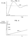
- Fig. 5 illustrates fluid volume displacement versus time after valve opening, with indication of the fluid acceleration and fluid half-cycle timing regions utilized, respectively, for low and high volume flow rates.
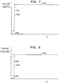
- Fig. 6 illustrates valve pulse frequency as a function of a linear rate-controlling parameter of the flow control system, including hysteresis in the transition between acceleration and half-cycle timing modes.
- Fig. 7 illustrates valve pulse width as a function of the linear rate-controlling parameter of Fig. 6, again showing the mode transition with hysteresis.
- Fig. 8 illustrates the bolus volumes corresponding to the pulse widths graphed in Fig. 7.
- Fig. 9 illustrates, in an overview block diagram, the control software method for regulating flow to track a volume target line over time.
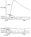
- Fig. 10 illustrates upstream and downstream valve pulse timings in relation to sensor volume changes in a hybrid operating mode, with infrequent maximum boluses from the source and frequent small boluses to the sink.
- Fig. 11 illustrates the single-valve, downstream flow restrictor embodiment of the system.
- Fig. 12 shows an electronic circuit schematic analogue of fluid flow dynamics in the controller of Fig. 11.
- Fig. 13 illustrates a maximum-bolus flow pulse with valve timing and volume sample timing for the system of Figs. 11 and 12.
- Fig. 14 illustrates a small-bolus flow pulse with valve timing and volume sample timing, analogous to the maximum-bolus traces of Fig. 13.
- Figs. 1a and 1b illustrate the same components except for the separation (Fig. 1a) or joining (Fig. 1b) of cassette 100 and controller 105.
- Fluid flow is to be regulated programmatically between a source 110 of variable fluid pressure and a sink 128 (at the far end of the outlet tube, not shown) at lower variable fluid pressure. Regulation is to take place in the disposable fluid-carrying cassette 100 when operating in clamped contact with the reusable controller 105, as shown in Fig. 1b.
- Cassette 100 receives from fluid source 110, here represented as a fluid-filled elastomer balloon, although any fluid source remaining within a suitable pressure range (e.g. 2 to 10 PSI) and not exhibiting excessive high-frequency variations in pressure (which could confuse the control algorithm) is likely to be suitable for the application described here.
- Deliverable fluid flows from this source at 110 through fluid channel 112, some fraction (including possibly a zero fraction) of which may be tubing and the remaining fraction of which may be part of cassette 100.
- fluid enters the opening/closing component 114 of the source control valve and, when 114 is open, continues via channel 115 into compliant volume displacement interface 116.
- fluid path 118 exits this interface area via fluid channel 118, which extends into opening/closing component 120 of the load control valve.
- 120 When 120 is open, the fluid path extends through channel 122 out of the cassette and into a region 124 of tubing which, for best system performance, should exhibit at least a minimum fluid volume/pressure compliance, as is discussed below.
- region 124 At the end of region 124 an optional flow restrictor, such as a length of microbore tubing or, alternatively, a pinhole restrictor may be included.
- the optional flow restrictor offers a safety feature in limiting flow rate in the event that both valves fail in an open condition.
- this flow restrictor is unnecessary to the functioning of the invention in this preferred embodiment, and the flow controller can adapt, in its servo control algorithm, to operation with or without this flow restrictor.
- Distal to tubing region 124 and the optional flow restrictor (if present) is an intravenous patient interface device, not shown, consisting of an inserted cannula or tube entering a vein.
- Figs. 1a and 1b represent the patient interface device and the patient simply as fluid sink 128, beyond the end of tube 124, the sink having some associated fluid pressure.
- the preferred embodiment is configured as a patient infusion device, it will be seen that the system can provide fluid pulses to many fluid sinks, e.g., in automated fluid dispensers for industrial applications.
- controller 105 Illustrated in the upper portion of Fig. 1a, above cassette 100, is controller 105, which includes source solenoid thruster 150, direct volume conversion device 152, and load solenoid thruster 154. Also included along with these just-listed key elements, but not shown in the figure, are an electrical power source (e.g. batteries or a line-operated D.C. supply), a microprocessor, power switching electronics to drive thrusters 150 and 154 under control of the microprocessor, and interface electronics between the microprocessor and device 152.
- an electrical power source e.g. batteries or a line-operated D.C. supply
- a microprocessor power switching electronics to drive thrusters 150 and 154 under control of the microprocessor
- interface electronics between the microprocessor and device 152.
- Two different embodiments of 152 are outlined below, similar in mechanical structure but differing in electronic and electromechanical construction and operation, yielding two corresponding descriptions for the interface electronics with 152. A more detailed description of the embodiments of 152 is found in
- Fig. 1b illustrates the mating of disposable cassette 100 with controller 105.
- controller solenoid thruster 150 may be seen to be controllably activated to exert a force on cassette valve opening/closing component 114.
- 150 and 114 together constitute a two-state (full-open of full-closed) fast-response source control valve. The force exerted by 150 on 114 causes this normally-closed valve to open for a controlled duration.
- V(f) a reproducible calibration function
- opening of normally-closed valve component 120 under the influence of controller solenoid thruster 154 depletes the volume in the interface region, registering a volume decrease and measured fluid delivery to the patient when before-and-after frequencies f are plugged into the V(f) calibration function.
- the magnitudes of the resulting fluid pulses are controlled by pulse duration but do not, in general, vary in even approximately linear proportion to pulse duration for the geometry and pulse interval range of the preferred embodiment.
- the preferred embodiment employs larger-than-capillary fluid pathways (typically not much less than one millimeter diameter), with the result that volume transfer as a function of time after valve opening approximates a damped sinusoid (Fig. 5), starting out at zero rate-of-change at the moment of valve opening, going through an acceleration phase and, if permitted by a long enough valve-open pulse, continuing into a deceleration phase up to a maximum achievable volume change. It is wasteful of valve actuation energy to extend a valve pulse beyond the natural period of one half-cycle of the flow response sinusoid, for any further increase in pulse duration only reduces the net volume transferred.
- the response to opening of 120 may be further complicated by the pulse wave guide nature of tube 124 and other characteristics of the load, including possible flow restrictor 126.
- the dynamics just described will be discussed in more detail with reference to the impedance schematic of Fig. 4.
- Figs. 2a and 2b we observe the opening/closing valve component 114 of cassette 100.
- Component 120 is similarly constructed. In Fig. 2a, 114 is closed, while in Fig. 2b, 114 is open. The figures are otherwise the same.
- valve structure that resembles a passive one-way check valve, oriented here to be closed against flow rising from below via passageway 112 into cavity 205 and to open, at some forward cracking pressure, when pressure in passageway 115 exceeds the pressure in 205.
- active servo-valve 114 operates for flow in the normally-checked reverse direction.
- Elastomer disk 210 seats on lip 212 in response to a reverse bias, isolating cavity 205 below from passageway 115 above. At zero and small forward biases below the cracking pressure, the preload bending of 210 by the upward thrust of center post 214 maintains 210 seated.
- cup 220 is held by circumferential "living" hinge 222 in relation to the surrounding region 224 of the cassette.
- 222 is a thin plastic annulus, curving axially downward (as illustrated, though upward curvature would work) and back upward along any radial path from the inside to the outside diameter of the thin annulus.
- annulus 222 bends near the inner and outer perimeters and flattens somewhat in the middle to permit 220 to move down, as shown in Fig. 2b.
- the rim of 220 then contacts disk 210 slightly inside of lip 212, and pushes down the edge of the disk, unseating it as illustrated.
- the thruster must overcome elastic forces in the living hinge, pressure forces associated with the area of 210 and the differential between pressure in 205 and pressure in 115, and pressure forces associated with the area of 220 plus part of the area of annular hinge 222 and the pressure differential between 115 and the environment above 220. A further increment of force is needed to overcome the pre-tension associated with the curvature of disk 210 and bend that disk to greater curvature.
- the valve geometry is small and the travel of 220 to open the valve is short, typically less than .020 inches to carry 220 from rest position out of contact with 212 into a full-down position with 212 unseated sufficiently for the valve opening to offer negligible flow resistance, compared to the largely inertial impedance of fluid-filled passageways leading to and from the valve.
- Solenoid thruster 150 is designed to accomplish this travel in roughly one millisecond, with the return transit time being similar, depending on the altered pressures in 205 and 115 after 210 is unseated and the valve effectively opened.
- the structure of valve opening/closing component 120 is the same as 114 except for differences in the connection of fluid passageway 118, as contrasted with 112, into the cavity below the disk.
- Thruster solenoids 150 and 154 are diagrammed based on the geometry and scale of potentiometer cores (pot cores) that can be modified to function as solenoids in the current invention. Wound bobbins are indicated in the centers of the pot cores, with axial magnetic gaps that are drawn toward closure when an electric current passes through the bobbin winding. With the bottom half of either pot core fixed and the top half able to travel downward, the excited magnetic field pulls the top half down, driving down thruster rod 160 of solenoid 150 or its counterpart in solenoid 154.
- solenoids 150 and 154 can be accomplished by other transducer approaches.
- Another approach is to derive thrust from a piezoelectric bender or bender stack. The thrust involved is within reach of bender stack technology, though somewhat expensive to achieve and demanding of a high supply voltage to drive the bender. Electromechanical efficiency of the piezoelectric approach for this application is fairly good.
- Fig. 3 shows a volume transfer fluid 315 isolated from the deliverable fluid in the volume displacement area 116 of the cassette by two barriers: 117, an elastic barrier that is part of the cassette and contains the deliverable fluid; and 310, an elastic barrier that is part of the controller and contains the volume transfer fluid.
- Barrier 310 is shown not as a membrane, but rather a comparatively thick elastomer plug, being proportioned to hold its shape and present a convex surface upon mating with membrane 117.
- the footprint where the convex surface of 310 meets 117 spreads from a point of initial contact to cover the entire interface area, with the objective of leaving no air pockets.
- the preload shape of 310 pushes 117 into cavity 116 at low fluid pressure, displacing some fluid out of the cassette.
- the high end of the pressurization range will deflect the lower surface of 310 to flatness and on to concavity.
- a symmetric swing from convex-down to convex-up achieves the greatest volume transfer for a given membrane stretch.
- barriers 117 and 310 may be omitted, in which case fluid volume transfer fluid 315 will be part of the deliverable fluid. Properties of the deliverable fluid will affect the volume displacement measurement process, but in some contexts, fluid property variations will be of minimal significance.
- the volume displacement sensor called “DVC” for "Direct Volume Converter”
- DVC Direct Volume Converter
- gas inclusion in either the deliverable fluid or the volume transfer fluid adds an extra compliance, altering the relationship of volume displaced into the sensor area to either pressure change or deflection of sensing elements. Gas may be present and interacting with fluid volume change only if it is present in a controlled volume, e.g., for the intended purpose of adding a known volumetric compliance.
- the volume transfer fluid (which may or may not be distinct from the deliverable fluid) communicates from region 315 via orifice 320 with region 325, where fluid is captured between rigid surface 340 and spring plate 330.
- plate 330 performs dual functions: as a volume displacement spring, giving a repeatable curve relating pressure to volume displacement; and as a resonator plate whose resonance frequencies are sensitive to the plate distortions associated with fluid volume displacement. More specifically, as fluid enters cavity 325 beneath the plate via 320, the plate surface is deformed upward while the fluid layer between 330 and 340 thickens.
- vibratory bending in the plate stores elastic potential energy Ep in the plate, while the motion of unbending (and passing through a shape of minimum elastic energy) entrains radial fluid motion under the plate, e.g., with fluid in the thin layer moving radially outward as the center of plate 330 descends while the perimeter region rises.
- M0 an effective mass associated with the plate
- RHO the density of the volume transfer fluid under the plate
- M1 a coefficient relating to the plate geometry
- Q the volume of fluid captured in the thin layer between the plate and the rigid surface below the plate.
- K K0 + K1*Q 2
- K1 K0 + K1*Q 2
- the volume-squared coefficient K1 exists because the plate is least stiff when it is flat and becomes stiffer as fluid accumulating under the plate bends the surface into a curve. It is seen, therefore, that frequency OMEGA rises with increasing volume Q because of two combined effects, the thickening of the fluid layer lowering effective fluid inertia, and the nonlinear stiffening of the plate as pressure bends its surface toward greater curvature.
- a pre-curved plate will behave differently than an initially flat plate.
- plate 330 as drawn, includes a flat center region and an annular bump near the outer perimeter.
- the annular bump permits greater deflection of the plate surface by volume change without developing excessive stress or pressure change.
- a completely flat plate is more compliant than the ridged plate drawn, but for large perturbations, tension in the bowing flat plate quickly dominates over bending stresses in the surface, giving rise to a cube-law term relating pressure to volume increase.
- the linear pressure/volume coefficient is higher, while the cube-law coefficient is substantially smaller, permitting much larger volume perturbations in a comparatively linear region.
- the resonant frequency of the plate can be determined electronically by coupling to the plate an electromechanical transducer capable of exciting a volume-sensitive resonant mode.
- the mechanical resonance feature will be mirrored by a feature in the electrical impedance versus frequency function of the transducer.
- the electromechanical transducer is indicated as a thin piezoelectric ceramic disk 335 laminated to the center region of plate 330, with twisted wires 345 communicating between conductive surfaces on 335 and oscillator circuitry not shown.
- the disk-plate lamination shown will be recognized as a piezoelectric bender configured like a buzzer, such as is found in many smoke alarms, telephones, pager beepers, etc.
- FIG. 1a illustrates a voice coil driver coupled via a small screw and nut to the center of the vibrating plate.
- the left side of the cross-section of the circular voice coil is indicated at 160 (Fig. 1a), the coil moving in a magnetic field gap between center iron piece 165 (which is a plate on top extending down into a post going into the middle of the coil) and annular iron plate 170, the field being generated by ceramic magnet 175 sandwiched between 165 and 170 in a conventional voice coil driver configuration.
- the easiest way to obtain regenerative oscillation with a voice coil driver is to include a velocity-sense winding along with the primary driver winding (as is done in some integrated loudspeaker/amplifier designs). Voltage in the sense winding will be proportional to coil velocity. Alternatively, a voltage proportional to voice coil velocity can be detected directly in a single-winding voice coil, e.g., by placing the voice coil in a balanced bridge circuit designed to null the differential output signal from the bridge when the voice coil is not moving. This bridge circuit then yields a velocity indication as its imbalance output.
- the plate could be excited by a moving magnet rather than a moving coil transducer, or indeed by any transducer capable of transforming back and forth between electrical and mechanical energy and interacting with the resonance of the plate.
- the Direct Volume Converter design is not a true transducer between volume change and electrical energy, because pressure-times-volume energy does not translate directly or reversibly into charge-times-voltage energy on the electrical side in the normal volume-sensing mode of operation. Rather, low-frequency volume changes alter the conditions under which a high-frequency transducer-mediated oscillation takes place, with the resulting frequency being useful for volume sensing.
- a true transducer includes some component of passive, reversible transformation of energy between two forms, e.g., electrical to mechanical and back to electrical.
- a resistive strain gauge sensor is another example of a sensor that is a signal converter but not a transducer.
- hole 320 communicating between fluid in 315 and fluid in 325 is off-center.
- the hole is intentionally placed as near as possible to a pressure node for the plate vibration mode being used in volume sensing. This minimizes the coupling between the plate, in its oscillatory vibration mode, and any mechanical load properties associated with cavity 315 and things coupled to 315, so that oscillation frequency is unaffected by conditions outside cavity 325.
- This hole location minimizes the effect of any environmental noise that might interfere with the sensed oscillation. This location of hole 320 also helps minimize unwanted noise coupling away from the plate into the outside environment.
- the Direct Volume Converter design just described here briefly is not the only applicable form of volume sensor for a fluid flow controller.
- the DVC design is primarily a volume sensor, by the physical nature of the alterable inertia of a captured volume of water in a fluid layer between plate 330 and surface 340, and secondarily it is a pressure sensor, by virtue of the consistent spring response of the plate to give a change in pressure for a change in volume. Pressure is calibratable, while volume response is likely to be more consistent and stable than pressure response.
- a volume spring i.e. an apparatus that gives a consistent pressure versus volume relationship, and attach a conventional pressure transducer to the volume spring to obtain a volume displacement sensor usable in the current invention.
- FIG. 4 an electronic circuit schematic whose current/voltage relationships are analogues of the flow/pressure relationships in cassette 100 of Figs. 1a and 1b.
- battery 410 grounded at its negative terminal, delivers a positive voltage that is analogous to pressure P from fluid source 110.
- Fluid channel 112 may be characterized by an effective flow inertia and fluid-ohmic resistance, represented respectively by inductor 415 and resistor 420.
- Valve opening/closing component 114 is analogous to the channel in field-effect transistor 425, while thruster shaft 160 of solenoid 150 functions as control voltage Vc1, at 430, coupled through the gate of the transistor to turn the transistor full-on or full-off.
- the volume displacement sensor including cavity 116 and the apparatus coupled above 116 is represented by series resistor 435, inductor 440, and capacitor 445, which is grounded on the other side.
- Capacitor 445 represents the volume/pressure compliance of the volume displacement sensor.
- the volume-sensing function of the sensor amounts to detecting the charge on capacitor 445 (e.g. by measuring the voltage across the capacitor and multiplying by the capacitance) and converting the measurement into an appropriate output signal (e.g., voltage-to-frequency conversion for analogy to a volume-to-frequency converter).
- Valve opening/closing component 120 is analogous to the channel in field effect transistor 450, with the actuation via control voltage Vc2 at 455 via the gate of the transistor analogous to the actuation of solenoid assembly 154.
- Flow inertia in channel segments 118 and 122 is collectively represented by inductor 460.
- Flow resistance in segments 118 and 122 sum to give part of the resistance in resistor 465.
- Tube 124 is represented by the remaining resistance in 465 and the capacitance in 470, which is returned to ground on the opposite side.
- the impedance of tube 124 is actually more complicated than the schematic suggests, as is discussed below, although the circuit schematic representation presented is adequate to analyze the essential functioning of 124 in the current system context.
- a flow restrictor e.g., microbore tubing
- the net resistance at the load end, including the flow restrictor if any, is represented by resistor 475.
- the load itself represented by box 480 connected between the "distal" side of resistor 475 and ground, may present "ground" potential to the termination of 475, i.e. zero gauge pressure, or it might present a time-varying potential, representing, e.g., the pulsating artery of a patient or a vein in an arm that is going up and down, causing a variation in head height.
- tube 124 To model the impedance to tube 124 properly, one must take account of its wave propagation properties. For quick discharge from capacitance 445 via valve channel 450 into the tube, it is necessary that tube 124 be physically relatively large and of some significant compliance. A standard PVC tube with .065 inch inside diameter and .125 inch outside diameter is of an appropriate scale, while the substantially smaller tubing used in some IV sets will not be compatible with short valve pulses. Regardless of the volumetric compliance that the tube set offers, as represented by capacitor 470, this compliance is not “seen” by the controller output over a flow pulse duration of 50 milliseconds or less, 50 milliseconds representing about the longest pulse time scale anticipated for most applications of the current invention.
- the .125 inch outside diameter PVC tube just mentioned for example, if flexible enough to expand in inside diameter by 15% under a pressure increase of 10 psi (this expansion being highly dependent on the PVC formulation, age, etc.), will exhibit a wave propagation velocity on the order of 15 meters/second, along with a fairly rapid dispersion and blunting of the wavefront due to damping components of the tube elasticity. This implies that over 50 milliseconds, only 30 centimeters of tubing length will have expanded in response to the flow pulse from the proximal side, while any remaining length will not have felt the pulse arrival.
- the impedance at the tube inlet will not "feel" the effect of the far end of the tube until the pulse wave has propagated all the way to the far end and reflected back, implying that over a 50 millisecond pulse, flow into the tube set will not be affected by a tube termination any farther than 15 centimeters from the proximal end.
- the flow impedance at the proximal end of the tube is substantially resistive. This is not because of dissipative tubing resistance, but because flow energy into the tube creates a propagating wave that carries elastic and kinetic energy with it.
- a substantial resistance at 475 can be advantageous for steady infusion.
- a pressure potential quickly builds up in 470, i.e. compliant tube 124, to drive the controlled average flow into the load.
- the accuracy of flow control will be unaffected.
- Head height variations in load pressure at 480 will not reverse the flow into the load except for a positive head height change exceeding the bias pressure differential established across resistance 475.
- resistor 475 has the effect of minimizing the sensitivity of short-term infusion rate to head height variations in 480. (In the long term, the controller imposes the prescribed infusion rate, so only short term effect involving charging or discharging capacitance 470 are of concern here.)
- 475 is large, there is also a filtering action to smooth out the bumps due to flow pulses across 450.
- a large resistance at 475 is not essential to the proper functioning of the flow controller, which will adapt to achieve the prescribed flow regardless of load resistance, so long as sufficient pressure is available from the source to drive the prescribed quantity of fluid into the load.
- the volume-versus-time response after opening either the proximal or distal control valve is represented qualitatively by Fig. 5, showing a damped sinusoid starting at zero slope at the instant of valve opening and oscillating about dashed equilibrium line 520.
- the volume change from the horizontal start of the volume curve up to the level of dashed line 520 is the product pressure-times-capacitance, for the pressure differential across the selected valve just before turn-on and the fluid capacitance of 445, the volume displacement sensor, which is the only capacitor in the short-time-constant dynamic model. It is entirely possible for the flow pulse response to become overdamped and exhibit no overshoot, depending on the design of the fluid path.
- valve-open time will therefore be set to give shutoff at point 500, right at the peak of the volume transfer curve. If flow impedances affecting cassette operation are not accurately known in advance in terms of controller algorithm coefficients, the controller will "experiment" with valve-open timing over a number of pulses to determine empirically the time interval to point 500, i.e. the time interval that maximizes the volume bolus.
- volume overshoot at 500 represents a pressure overshoot that will reverse the pressure bias in the check valve at closure.
- a valve like that represented in Fig. 2a could potentially leak in the "forward" direction of the valve regarded as a passive check valve, i.e. with flow from 115 down into region 205.
- a transient volume loss due to valve leakage of this sort will not cause harm, so long as the volume stabilizes for measurement of net displacement before the opposite valve opens to restore the normal bias direction to the valve that was tending to crack.
- valve regurgitation will lessen the net bolus transfer size, most likely for working source-to-sink pressure differentials at the high end of the design range for the system, where a self-limiting of bolus size could even be beneficial by making maximum bolus size less sensitive to supply pressure.
- Valve closure well past point 500 on the volume curve makes no sense, being wasteful of valve actuation power while achieving less than the volume transfer accomplished with a half-period pulse. Valve closure in the high-flow region before 500 is undesirable because of the waterhammer effect. Very early valve closure, e.g. at 510, early in the flow acceleration phase, can be used for variable control of small boluses with shutoff into a comparatively slow flow rate.
- Q is used to represent fluid flow rate, i.e. volume per unit time. Elsewhere, Q refers to the quality factor of a resonant circuit, the reciprocal of the dissipation factor. In electrical engineering and electronics, Q represents electric charge. In the following text, Q is taken, unconventionally, to represent fluid volume or, mnemonically, "Quantity.” This fluid Q is conveniently analogous to charge Q in the electrical analog of the fluid circuits.
- the time derivative is often designated by a dot placed above the variable, but to avoid special characters, the character string D1Q will represent first derivative of Q with respect to time, i.e. flow, and D2Q will represent the second time derivative, i.e. fluid volume acceleration.
- P is pressure, analogous for voltage.
- L, R, and C are carried over directly from their electrical circuit meanings to their analogous fluid circuit meanings.
- THK SQRT(MU/(2*OMEGA*RHO)
- This thickness parameter has two dynamic applications: dissipation thickness, and displacement thickness.
- a fraction of the fluid moving in the tube is phase-shifted 90 degrees ahead of the acceleration-limited fluid, to the phase angle of resistance-limited fluid flow, flow which dissipates fluid power rather than storing the power in kinetic energy.
- This fraction for thin boundary layers, represents the volume lying within a distance THK of the tube wall, i.e. the same volume that was removed as displacement thickness.
- THK represents dissipation thickness as well as displacement thickness.
- the boundary layer thickens with lowering frequency, the velocity profile settles into the limiting shape of a paraboloid going from twice the average cross-sectional velocity at the center to zero velocity at the tube wall. Looking at the kinetic energy in the flow in relation to the average velocity across the cross-section (i.e. that which multiplied by area gives flow rate D1Q), it works out that the energy is raised by the ratio 4/3, which implies that flow inductance L is 4/3 times the high-frequency limit value in the low-frequency limit.
- OMEGA 1/SQRT(L*C)
- Eq. 11 may be solved for R, followed by solution for RE, IM, and the function Q(t).
- this form of solution can be applied to the flow pulse shape for pulsing of either the proximal or distal valves in the preferred embodiment of the controller, in general using different component values for L and R depending on which valve is pulsed, but with C remaining the same.
- 450 we still need a formula for estimating the contribution of wave impedance in tube 124 to resistance in 465. The following formulas are used in modeling of pulsatile flow in arteries.
- dP/dA is measured statically or at low frequency with a tube whose wall material exhibits creep, e.g., PVC tube, then the value obtained will be lower than for the frequency range of pulse wave propagation in the current context.
- the derivative dP/dA is always an increasing function of frequency in lossy polymer materials, and the higher the dissipation of the material, the steeper the frequency slope.
- the important issue is to determine whether the magnitude of R is going to be large enough to cause overdamping of the flow pulse through valve 450. If there is overdamping and a controller algorithm is extending a pulse interval seeking a maximum bolus volume, the pulse interval will be stretched out to the point where a return wave reflection reverses the volume flow into tube 124, which may be too long to wait if solenoid power is being consumed. It may prove practical to work with an overdamped output pulse, in which case the pulse duration for large boluses should be limited to some interval of diminishing volume returns for the actuator energy investment. (If a piezoelectric valve actuator is used, the energy conservation question is moot, since holding charge on the actuator capacitance does not use power.)
- FL is a non-dimensional parameter that controls flow. Actual flow rate is nearly linear with FL, provided that the flow control algorithm coefficients are matched to the time constants and damping factors of the fluid delivery system.
- Q.NET is defined as total measured infused volume, whose graph against time will be a stairstep function incremented at each infused bolus.
- FLOW delta(Q.NET)/delta(TIME) over one pulse period Volume/Time rate
- FLOW depends on control parameter FL multiplied by the difference between source pressure P.SOURCE and sink pressure P.SINK and further multiplied by a system flow scaling coefficient KF according to the equation:
- FLOW KF*FL*(P.SOURCE-P.SINK)
- the coefficients for getting from FL to those pulse frequencies and widths are adjusted dynamically so that Eq. 20 is satisfied. That is, FLOW as a controller target is used to compute FL, then FL sets pulse widths and frequencies, and the result is to cause a measurable delta(Q.NET) that is used to solve Eq. 20 for achieved FLOW. To the extent that achieved FLOW misses the target value of FLOW used in Eq. 22 to compute FL, the coefficients going from FL to pulse control parameters are adjusted.
- the coefficient KF is not adjusted, but is simply for convenience of scaling the numerical range of FL, e.g., so that FL runs nominally from 0 to 1 to cause flow to vary between 0 and the maximum rated throughput for the system.
- pulse frequency is graphed as a function of parameter FL.
- pulse width 710 (Fig. 7) is kept constant, which keeps pulse volume 810 (Fig. 8) constant except for possible variations due to head height changes.
- the pulse width in this region is adjusted to approximate point 500 (Fig. 5) of maximum volume transfer unless, in an overdamped system, valve closure is imposed before flow completely stops.
- the result of a linear variation in frequency at constant pulse volume is a linear variation in FLOW.
- pulse frequency reaches a lower limit, below which more frequent pulses are needed for flow continuity. This limit may be on the order of .05 per second (three per minute), or possibly smaller if a large termination flow resistance 475, in conjunction with a comparatively large tube compliance capacitance in 470, yields adequate smoothing of the flow boluses.
- pulse frequency jumps up (620) while pulse width jumps down (720), causing pulse volume (820) to jump down by a much larger ratio.
- the operating point has moved on the VOLUME/TIME graph from 500 to the vicinity of 510, in early flow acceleration. In this region, labeled by 630, 730, and 830, pulse volume varies nearly as the square of pulse width, which gives larger fractional changes in pulse volume than occur in pulse width.
- both pulse frequency and width vary as the cube root of FL in the variable-bolus region.
- the controller is not inherently noisy, it is difficult to engineer the design to be completely inaudible under all conditions.
- the controller pulses are likely to be audible. If their rhythm is regular, like ticks of a clock, the pulse sounds will be readily ignored. If the rhythm jumps from slow to fast or fast to slow, probably accompanied by a change in sound quality because of the pulse interval change, attention will be called immediately to the noise.
- Fig. 9 is a functional block diagram for a preferred controller method.
- Each block represents a software module which receives input parameters, performs computations, and delivers output parameters.
- the timings as well as the values of input and output parameters are of significance, i.e. the parameters are of a dynamic nature for real time control.
- the "FLOW TARGET LOGIC” module 902 computes the flow control parameter "FL" based on a moving target for delivered volume, interpreted in relation to "VOLUME" sensor inputs via 904 from Direct Volume Converter "DVC" 152 (of Fig. 9, first seen in Fig.
- the output parameter of 914 is passed via path 916 to hysteresis module 918, whose output is binary parameter "SELECT" on 920.
- 918 compares its input from 916 to upper and lower threshold values and sets "SELECT" to "TRUE” whenever the input exceeds the upper threshold, and to "FALSE” whenever the input falls below the lower threshold.
- a graph of "SELECT" against input 916 shows a hysteresis loop, as indicated by the shape diagrammed in box 918. The combination of low-pass filtering and threshold hysteresis avoids jitter between operating modes, as described above.
- Module 926 represents the choice of Pulse Frequency “PF” and Pulse Width “PW” in fixed maximum bolus mode, Mode B, with the bolus volume target and corresponding pulse interval time represented at point 500.
- the width coefficient "BW” is adjusted to achieve this peak volume at 500 and is the height of line 710.
- the frequency coefficient "BF” is the slope of line 610 and is chosen for the range of frequencies appropriate to the mechanical and fluidic design with its range of source pressures and rate targets.
- Module 924 represents the choice of "PF” and “PW” in variable bolus mode, Mode A. As discussed earlier, PF and PW are set proportional to the cube root of FL with frequency scaling coefficient “AF” to give “PF” and width scaling coefficient “AW” to give “PW”. The resulting PF curve is 630, and the resulting PW curve is 730. The values of "AF” and “AW” are chosen in relation to "BF” and “BW” and a best estimate of the shape of the VOLUME(TIME) function curve of Fig.
- modules 924 and 926 provides output parameters PF and PW via paths 928 and 930 to "VALVE B TIMING" module 932.
- This module provides the real-time binary control signal “DRIVE B” on 910, whose pulse width and pulse frequency control timing of the power driver circuit for valve assembly “B” at 154.
- the signal on 910 also provides synchronization to "FLOW TARGET LOGIC” module 902 for determining when to read volumes for computation of net delivered volume.
- VALVE B TIMING seeks to maintain a prescribed flow rate out to fluid "LOAD” 480, via feedback through the "FLOW TARGET LOGIC” at 902, the software module “VALVE A TIMING” at 934 operates only in maximum fixed bolus mode and functions only to replenish the volume in fluid capacitance 445, which is the volume sensed in "DVC" 152, whenever that volume becomes too depleted. Hence, 934 monitors the parameter "VOLUME” from 152 via path 904 to its input, and activates whenever “VOLUME” falls below a prescribed threshold.
- That threshold depends on the operating mode indicated by the input "SELECT” via 920 from 918, and depends upon an estimate from "FLOW TARGET LOGIC" 902 of the pressure span from the fluid source to the fluid load at tube 124.
- 934 is set to fire a pulse to 150 via output 908 whenever valve B at 154 fires and depletes the volume sensed in 152. This firing is delayed by a short latency interval to allow for an accurate volume reading but is more or less immediate, so that the fluid reservoir of 152 is waiting full and ready for the next output pulse.
- variable-bolus mode A for valve B as indicated when "SELECT" on 920 is "FALSE" the volume threshold for 934 is set toward the center of the available operating pressure range from source to sink. This setting, which varies the volume bias at which 152 senses, may be fixed or varied at will. A high setting results in more frequent pulses of valve A at 150, less frequent pulses of valve B at 154, less fractional variation in pressure in 470, and consequently less fractional variation in pulse frequency PF.
- the relationships described here are better understood with reference to the timing diagram of Fig. 10.
- the declining "VOLUME” signal on 904 is indicated by curve 1004, which declines in small increments with each pulse to valve B on 910, indicated by pulse train 1010.
- 1004 reaches a minimum threshold, it triggers the logic in 934, whose immediate response is to set "INHIBIT” to "TRUE", where "INHIBIT” is the parameter being passed symbolically via 936 from 934 to 932.
- the signal on 936 is graphed against time as 1036.
- valve A activation signal 908 pulses high and low, as plotted against time on curve 1008, giving a maximum-bolus interval.
- Volume on 1004 swings up through a half-period of the damped sinusoid of Fig. 5 and is stopped by valve closure at the top.
- An interval elapses after valve closure for a second highly accurate volume determination, following which "INHIBIT" signal 936 as shown on trace 1036 goes low, i.e. "FALSE", and valve B pulsing is allowed to resume, causing volume on 1004 to descend by small steps. Not visible on the scale of Fig.
- the descending steps of curve 1004 are downward curving parabolas, starting from horizontal tangency and bending downward until the descent is interrupted abruptly by valve closure.
- the accurate volume determinations in the inhibit intervals just before and just after the pulses of 1008 are used to track the total volume delivered to the fluid sink. Intermediate volume determinations are not critical for accuracy, being used just for control monitoring.
- Fig. 10 is correct for the above qualitative description, the time scale of the features has been distorted for clarity of illustration.
- the widths of pulse-high intervals of traces 1008, 1036, and 1010 are much narrower in relation to the time baseline, which causes the transitions in graph 1004 to be correspondingly steeper, appearing vertical on the time scale drawn.
- the variable-bolus pulses of trace 1010 could be of the order of three milliseconds wide and spaced at one second intervals, implying a high-state duty cycle of .003.
- the pulse width on 1008 could be of the order of thirty milliseconds.
- the high-state duty cycle on 1008 would then become .002. On this time scale, the S-shape of the volume rise on 1004 would not be visible.
- the width of pulses on trace 1036 in excess of the pulses on 1008 might be on the order of fifty milliseconds extra before and again after the pulse on 1008, to allow for settling of transient vibrations and a frequency count interval of perhaps ten milliseconds. This pushes the pulse widths on 1036 up to 130 milliseconds, which fits well within the pulse interval for the pulse train of trace 1010.
- the refill pulses of 1008 and the surrounding inhibit intervals of 1036 could fit into latency intervals between pulses of 1010, giving an uninterrupted rhythm of output pulses, with (e.g.) every fifteenth pulse sounding a little different because two events, an input pulse and an output pulse, fall within a 100 millisecond interval and are barely resolved by the ear as separate events.
- "FLOW TARGET LOGIC” module 902 monitoring curve 1004, infers from the volume reading the associated pressure, and infers from the volume increment sizes what the fluid load pressure has to be, consistent with the known flow dynamic characteristics of the controller. From the resulting inference of pressure differential between fluid capacitors 445 and 470, 902 adjusts parameter FL dynamically to achieve constant fluid boluses, applying Eq. 22. Thus, the pulse frequency and width of 1010 will become larger as the volume reading on 1004 descends, and frequency and width will shrink again as 1004 jumps back up.
- the function of the "FLOW TARGET LOGIC" module 902 is to take a target net volume, V.T, which moves with time at an associated target volume rate D1V.T, and cause the net delivered volume stairstep function Q.NET and its one-cycle slope, FLOW, to close simultaneously with the targets V.T and D1V.T.
- Eq. 23 assigns a value to FLOW according to past volume delivery performance, then Eq. 22 assigns a value to control parameter FL based on FLOW and estimated pressure conditions.
- TAU is a time constant controlling system convergence. If TAU is set to the current pulse period, the effect will be to correct the error (V.T-Q.NET) in a single pulse step. Setting TAU any shorter will cause overcorrection and possibly instability. Setting TAU longer than the minimum will prevent the system from jittering and over-responding to external variations such as "noise” variations or pulsations in load pressure. If TAU is extended to well over one pulse period, the implementation of Eq. 23 will cause volume error to decay over time with a time constant of approximately TAU. Implicit in Eqs.
- AF and BF are left constant while AW and BW are adjusted to calibrate FLOW in the two operating modes.
- An alternative operating mode is noted here, useful for very slow infusion. If the outgoing volume pulses via 154 need to be kept very small, this can be accomplished with a larger, more manageable pulse width if the fluid source at 152 is maintained at a pressure bias not much above that of the fluid load. This can be accomplished if the refill pulses to 150 are not maximum-bolus pulses, but much shorter pulses, in the flow acceleration phase.
- 152 is not “topped up” each time, but held to a low bias pressure.
- the timing diagram of Fig. 10 still applies in this case, qualitatively, except that the refill volume boluses are kept small, and the shape of the rising segments of 1004 is upward-curving parabolas chopped off at valve closure time, rather than S-shaped curves going smoothly to horizontal tangents at the top.
- valve 150 or 154 fails to close, e.g., because of a particle lodging and unseating disk 210 or its counterpart in valve 120
- the flow controller of the present system will immediately recognize the failure and will be able to maintain ongoing controlled infusion, although with a possible loss of accuracy.
- the system should be programmed to set off a malfunction alarm even as it continues operation, since redundancy in the system will be lost and the reliability of continued operation put in question.
- the controller will have derived flow control coefficients AF, AW, PF, and PW, that in conjunction with a good pressure differential estimate lead to a calibrated infusion rate using output valve B alone. Similar parameters will have been derived for input valve A. The net effect of system geometry and fluid properties is thus self-calibrated and the resulting coefficients available for open-loop control.
- source valve 150 fails open, the pressure proximal to sink valve 154 will rise to the source pressure, a situation immediately recognized by the controller.
- the controller will further have a good estimate of the difference between this source pressure and the load pressure, as well as an indication of the relationship between pulse width and pulse volume in the form of the adjusted flow control coefficients.
- the controller can therefore continue to pulse, open loop, delivering a comparatively accurate volumetric output to the sink, even though volume-change feedback data are no longer available. If the source supply becomes depleted, this will be measured directly by a drop in pressure at 152. If the fluid path to the sink becomes closed, then pulsing of valve 154 will cease to produce transient ripples in the output of 152, and the controller will know that flow has been interrupted.
- sink valve 154 fails open, the pressure distal to source valve 150 will fall to the load pressure, again an immediately recognizable situation for the controller. Guessing that the source pressure is maintained constant and with constant monitoring data on load pressure, the controller has a sufficient description of pulse width versus bolus volume characteristics of the source to maintain regulated flow. Pinching off of the fluid path to the sink will result in a readily observable rise in the volume signal from 152. Loss of source fluid will result in disappearance of the transient ripples from 152 that should normally accompany pulses from the source.
- the system described above uses two valves to permit accurate volume readings at zero instantaneous flow rate, giving an indication of total delivered volume.
- Two valves are not always necessary to the proper functioning of the invention, especially if the system need not function over an extremely wide dynamic range of precisely monitored rates.
- the failure mode described just above, for sink valve 154 stuck open, suggests a design that can regulate flow to a sink with just one valve.
- a flow restrictor just distal to the volume displacement sensor By adding a flow restrictor just distal to the volume displacement sensor, a dynamic is obtained in which on-the-fly volume readings can be interpreted to derive an accurate measurement of fluid flow to the load.
- a substantial downstream flow resistor adds safety, should the one valve in this second embodiment fail in an open state: there will not be a sudden rush of fluid to the output.
- the flow restrictor will passively slow the flow rate while an alarm sounds, giving time for an operator or the patient to intervene and prevent over-infusion.
- Tube 11 suggests that 1122 is a segment of microbore tubing.
- a pinhole restrictor could be used but may be less desirable, lacking the inductive impedance component that can be helpful in obtaining accurate dynamic volume readings.
- Tube 1124 is functionally no different than tube 124 except that there is no advantage to low pulse wave impedance, so 1124 can be a small tube.
- Tube 1126 functions no differently than optional tube 126 of the preferred embodiment, which was discussed above.
- proximal flow restrictor, 1122 provides the flow inertia, or inductance, to prevent abrupt changes in flow rate out of the volume sensor when an inlet pulse is applied to that sensor.
- the way this imposed sluggishness in flow rate change is used in volumetric delivery computation is described below.
- Connection of the sensor discharge directly to a larger tube, e.g. tube 1124, would give rise to a short-term resistive load, associated with compliance and related wave impedance of the tube.
- Distal flow restrictor 1126 serves the same function described for 126 in the preferred embodiment -- to smooth out flow pulses and avoid temporary flow reversal with change of head height. If tube 1124 is made small and of low volumetric compliance, then restrictor 1126 becomes less critical and might be omitted. Similarly, a small and not very volume-compliant tube 1124 will offer a high resistive impedance to short pulses, making estimation of delivered volumes less difficult even if restrictor 1122 is omitted. Hence, the design could be made to function well with a small low-compliance tube set and no additional flow restrictors.
- FIG. 12 The dynamic flow characteristics of the second embodiment are illustrated by schematic Fig. 12, which is analogous to Fig. 4 in all components except for valve path 450 and associated control 455, which are replaced by a direct fluid connection.
- Fluid path 1225 with control 1230 are analogous to 425 and 430, and capacitor-inductor-resistor combination 1245-1240-1235 (respectively) is analogous to the 445-440-435 combination, but the junction of 1225 and 1235 connects directly to inductor 1260, which is analogous to 460, without the intervention of a valve analogous to 450.
- inductor 1260 is substantially larger than 460
- resistor 1265 is very much larger than 465, by design.
- Tube capacitance 1270 is analogous to 470 but might be quantitatively much smaller if a small tube is used, as is allowable in the system context of this second embodiment.
- 1275 is analogous to 475 but might be larger, since this second embodiment will generally not handle the high flow rates of the first embodiment and can therefore tolerate higher-resistance flow restrictors.
- Load 1280 is analogous to load 480.
- Fig. 13 The dynamics of the single-valve system of Figs. 11 and 12 are illustrated in Fig. 13. for a maximum bolus and in Fig. 14 for a small variable bolus.
- the horizontal axes for Figs. 13 and 14 are time. Looking first at Fig. 13, volume trace 1310, the volume sensed between valve 1225 and outlet inductor 1260, responds to the valve-open pulse-high interval illustrated on trace 1320. Just before 1320 pulses high, 1310 is sloping down, following an exponential decay curve of fluid volume discharge.
- valve 1225 When 1320 goes high, fluid flow from valve 1225 accelerates and then decelerates to zero rate at the valve closure point where 1320 goes low, following a curve like that of Fig. 5 from the beginning up to the point labeled 500.
- fluid flow out of the volume sensor area via inductor 1260 and resistor 1265 is accelerating in response to the increasing pressure at the junction of 1260, 1225, and 1235.
- valve 1225 closes, the downward slope of trace 1310 has become steeper than before the recharge pulse.
- 1310 With continuing flow acceleration, 1310 continues to bend downward but soon goes through an inflection and settles into an exponential decay curve asymptotic to a limit-volume determined by pressure in the load.
- Pulse wave action in tube segment 1124 may in some embodiments cause further visible wiggles in the shape of trace 1310.
- the important point here is that there is always flow going out of sensor capacitance 1245 via 1260 and 1265, and during valve-open pulses, this flow is superimposed on incoming flow in the measurable sensor reading.
- the volume reading on 1245 cannot be sensed instantaneously or nearly so, but only over a count interval, typically of more than one and up to several milliseconds duration to obtain high resolution.
- the volume readings are smeared over the pulse-high intervals illustrated in trace 1330, labeled "SAMPLE".
- the controller must infer the net volume delivered to the load from these data using algorithms that take account of the dynamic nature of the measured fluid flow and the volume sensing process.
- Figs. 13 and 14 As with Fig. 10, the time scale of Figs. 13 and 14 has been distorted for illustrative clarity.
- the valve-open pulse of Fig. 13 is typically of the order of thirty milliseconds, while the interval to the next pulse is typically of the order of one second.
- the volume decay curve of trace 1310 is not nearly as steep, in proportion to the volume increase, as is illustrated. This means that accuracy of the dynamic representation is not as critical to overall volumetric determination as would be suggested from the waveform shapes of Figs. 13 and 14.
- the pulses on trace 1330 indicate that two volume samples are taken before the recharge pulse, and four after, the latter four starting immediately after valve closure and being spaced by increasing time delay intervals.
- the two pulses before the recharge pulse determine a volume and volume slope, establishing both volume and the flow status through 1260 and 1265 before the rapid pressure increase.
- the two pulses immediately following the recharge pulse similarly determine a new volume and flow rate. This new rate, however, is subject to a significant flow acceleration component, which is made evident by the third sample after the pulse.
- the final settling into an exponential decay is indicated by the fourth sample after the pulse.
- the six samples, each time-smeared over known intervals imply incoming and outgoing flows in a dynamic flow model.
- the simulation interpretation is developed first in the R&D sequence, typically using high level software to interpret sampled data and simply learn how to arrive at the desired solution for volume delivered, regardless of computation time.
- the simplified algorithm whose form can vary considerably, represents a synthesis, derived from the simulation interpretation, of a simple empirical formula that expresses, to good approximation, the results derived from the simulation.
- Fig. 12 For the simulation interpretation, one begins with the general dynamic description expressed by Fig. 12 and the equations shown above for reducing that figure to dynamic solutions.
- the inputs to the simulation are therefore the parameters of the system, including source and sink pressures, fluid density and viscosity, variables related to the geometry of the fluid controller system, and variables describing such things as tube set wave impedance and load impedance.
- the outputs are simulated volume samples. In an actual device, one has a number of the components of Fig. 12 reproduced fairly repeatably in successive flow control hardware units.
- the parameters corresponding to these controlled variables are taken as fixed constants, reducing the number of undetermined inputs to the simulation. Some of the system components will vary in the field, e.g., if different tube sets might be connected to the controller output, or if it proves that certain dynamic characteristics of the controller are not readily standardized and are likely to vary significantly from unit to unit.
- the uncontrolled parameters remain as unknown parameters of the model, while controlled parameters, e.g., the properties of the DVC volume sensing device, are removed from the list of unknowns. Source and sink pressures are among the unknown parameters.
- the problem at hand is then a variation on the well-explored but nonetheless challenging computational problem of functional minimization. As components of an input vector, one has the values of the unknown variables.
- an output vector one has a number (six in this example) of simulated volume averages, computed over the pulse-high sampling intervals of trace 1330. Then one has an equal number of empirically-measured volume averages. The output vector from the simulation, minus the empirically-measured vector, defines an error vector.
- the functional minimization problem is to vary the unknown parameters of the model to minimize the error vector. In general, one needs at least as many components of error vector as one has unknown system parameters to be determined, otherwise the error vector will not define the input vector uniquely.
- system parameters computed from volume measurements One inferred system parameter is of particular importance: the total fluid volume that passes through valve 1225 during the interval when 1320 is high. Given that, one knows how much volume is ultimately delivered to the fluid sink. The challenge is to estimate how much the minimum-to-maximum peak swing of trace 1310 is reduced by fluid flowing out through components 1260 and 1265 during the valve-open interval. Correcting for this reduction will yield the desired volume through 1225.
- Two other parameters are of operational importance: source and sink pressures.
- the functional minimization program yields each of these three parameters (i.e. input volume bolus, source pressure, and sink pressure) as three numerical functions of the values of the time-averaged volume samples. In the simulation and functional minimization process, it was necessary to solve for all the other unknowns of the system as well, but the remainder of the solution need not be embodied in the controller algorithm.
- the simulation model empirically matched to a bench prototype of a real, instrumented fluid delivery system, is a computational standard against which controller algorithms can be evaluated.
- volume bolus determination is pure curve fitting, with only a minor adjustment of the method based on empirical measurements. Ignoring the dynamic details behind the curves, one has a region of volume decay approaching the upswing region, a discontinuity in derivatives followed by a rapid volume upswing, a second discontinuity in derivatives, and a curve emerging from the upswing region.
- the curves on either side of the upswing region can be extrapolated without any reference to the underlying dynamics, provided that the first derivative is continuous and does not change too rapidly on a time scale comparable in duration to the valve pulse width.
- a delta-volume should then be computed between the forward- and backward-extrapolated curves, selecting some time point within the valve pulse interval for computing that difference.
- the volume sensor pressure can be varied intentionally by momentarily speeding up and then slowing down infusion, on a time scale short enough to be of no significance to the long-term delivery. These rate variations, reflected as pressure variations into the load, will reveal the change in source bolus volumes with sensor pressure, yielding the desired extrapolation to source pressure. Any further algorithmic sophistication in deriving source pressure lies in inferring, as accurately as possible, just what the bolus size is that flows into the volume displacement sensor as fluid simultaneously flows out toward the fluid sink.
- a volume trace 1410 analogous to trace 1310, starting with about the same fluid acceleration when the valve opens, except that the volume increase in truncated by a much earlier valve closure. A little ringing is shown at the valve closure, due to small compliances, e.g., in valve disk 210.
- the dynamic processes of rapid flow acceleration followed by gradual flow deceleration toward the fluid load are like those discussed earlier in relation to Fig. 13.
- a similar algorithmic determination of volume delivered with each pulse is performed.
- Flow target logic such as was described for the preferred embodiment keeps net infused volume very close to the moving infusion target.
Priority Applications (2)
| Application Number | Priority Date | Filing Date | Title |
|---|---|---|---|
| EP96650035A EP0763368B1 (de) | 1996-08-26 | 1996-08-26 | Dynamischer Fluid-Durchflussregler mit veränderbaren Impulsen |
| DE69611869T DE69611869T2 (de) | 1996-08-26 | 1996-08-26 | Dynamischer Fluid-Durchflussregler mit veränderbaren Impulsen |
Applications Claiming Priority (1)
| Application Number | Priority Date | Filing Date | Title |
|---|---|---|---|
| EP96650035A EP0763368B1 (de) | 1996-08-26 | 1996-08-26 | Dynamischer Fluid-Durchflussregler mit veränderbaren Impulsen |
Publications (3)
| Publication Number | Publication Date |
|---|---|
| EP0763368A2 true EP0763368A2 (de) | 1997-03-19 |
| EP0763368A3 EP0763368A3 (de) | 1997-04-09 |
| EP0763368B1 EP0763368B1 (de) | 2001-02-28 |
Family
ID=8225520
Family Applications (1)
| Application Number | Title | Priority Date | Filing Date |
|---|---|---|---|
| EP96650035A Expired - Lifetime EP0763368B1 (de) | 1996-08-26 | 1996-08-26 | Dynamischer Fluid-Durchflussregler mit veränderbaren Impulsen |
Country Status (2)
| Country | Link |
|---|---|
| EP (1) | EP0763368B1 (de) |
| DE (1) | DE69611869T2 (de) |
Cited By (43)
| Publication number | Priority date | Publication date | Assignee | Title |
|---|---|---|---|---|
| WO2002004046A2 (en) * | 2000-07-07 | 2002-01-17 | Fluidsense Corporation | Infusion pump cassette |
| DE10120543A1 (de) * | 2001-04-26 | 2002-11-07 | Ruediger Groening | Arzneimittelpumpe mit programmierter Abgaberate |
| EP1582232A1 (de) * | 2004-04-03 | 2005-10-05 | Codman Neuro Sciences Sàrl | Ventil zur Verwendung in implantierbaren Infusionspumpen |
| WO2007092618A3 (en) * | 2006-02-09 | 2007-12-06 | Deka Products Lp | Fluid delivery systems and methods |
| WO2008080552A2 (de) * | 2006-12-29 | 2008-07-10 | Bartels Mikrotechnik Gmbh | Verfahren und vorrichtung zur durchflussmessung |
| CN101342397B (zh) * | 2008-06-17 | 2011-03-23 | 杨建平 | 蓄压式输液器 |
| US8016789B2 (en) | 2008-10-10 | 2011-09-13 | Deka Products Limited Partnership | Pump assembly with a removable cover assembly |
| US8034026B2 (en) | 2001-05-18 | 2011-10-11 | Deka Products Limited Partnership | Infusion pump assembly |
| US8066672B2 (en) | 2008-10-10 | 2011-11-29 | Deka Products Limited Partnership | Infusion pump assembly with a backup power supply |
| US8141844B2 (en) | 2005-10-26 | 2012-03-27 | Codman NeuroSciences Sàrl | Flow rate accuracy of a fluidic delivery system |
| US8223028B2 (en) | 2008-10-10 | 2012-07-17 | Deka Products Limited Partnership | Occlusion detection system and method |
| US8240635B2 (en) | 2005-10-26 | 2012-08-14 | Codman Neuro Sciences Sárl | Flow rate accuracy of a fluidic delivery system |
| US8262616B2 (en) | 2008-10-10 | 2012-09-11 | Deka Products Limited Partnership | Infusion pump assembly |
| US8267892B2 (en) | 2008-10-10 | 2012-09-18 | Deka Products Limited Partnership | Multi-language / multi-processor infusion pump assembly |
| US8414563B2 (en) | 2007-12-31 | 2013-04-09 | Deka Products Limited Partnership | Pump assembly with switch |
| US8496646B2 (en) | 2007-02-09 | 2013-07-30 | Deka Products Limited Partnership | Infusion pump assembly |
| US8579884B2 (en) | 2006-02-09 | 2013-11-12 | Deka Products Limited Partnership | Infusion pump assembly |
| US8613724B2 (en) | 2009-12-31 | 2013-12-24 | DEKA Products Limted Partnership | Infusion pump assembly |
| US8708376B2 (en) | 2008-10-10 | 2014-04-29 | Deka Products Limited Partnership | Medium connector |
| US8784364B2 (en) | 2008-09-15 | 2014-07-22 | Deka Products Limited Partnership | Systems and methods for fluid delivery |
| US8852164B2 (en) | 2006-02-09 | 2014-10-07 | Deka Products Limited Partnership | Method and system for shape-memory alloy wire control |
| US9173996B2 (en) | 2001-05-18 | 2015-11-03 | Deka Products Limited Partnership | Infusion set for a fluid pump |
| US9180245B2 (en) | 2008-10-10 | 2015-11-10 | Deka Products Limited Partnership | System and method for administering an infusible fluid |
| US9194110B2 (en) | 2012-03-07 | 2015-11-24 | Moen Incorporated | Electronic plumbing fixture fitting |
| US9492606B2 (en) | 2006-02-09 | 2016-11-15 | Deka Products Limited Partnership | Apparatus, system and methods for an infusion pump assembly |
| US9662438B2 (en) | 2010-02-05 | 2017-05-30 | Deka Products Limited Partnership | Devices, methods and systems for wireless control of medical devices |
| US9750896B2 (en) | 2010-02-05 | 2017-09-05 | Deka Products Limited Partnership | Infusion pump apparatus, method and system |
| CN111551223A (zh) * | 2019-02-12 | 2020-08-18 | 西门子股份公司 | 用于具有脉冲流的流体的流量计 |
| CN114183794A (zh) * | 2021-12-20 | 2022-03-15 | 河北同力自控阀门制造有限公司 | 一种基于不平衡率的静态水力平衡智能调节方法 |
| US11364335B2 (en) | 2006-02-09 | 2022-06-21 | Deka Products Limited Partnership | Apparatus, system and method for fluid delivery |
| CN114739470A (zh) * | 2022-04-14 | 2022-07-12 | 福州大学 | 基于高频动态压力信号测量高速开关阀流量脉动的方法 |
| US11404776B2 (en) | 2007-12-31 | 2022-08-02 | Deka Products Limited Partnership | Split ring resonator antenna adapted for use in wirelessly controlled medical device |
| US11478623B2 (en) | 2006-02-09 | 2022-10-25 | Deka Products Limited Partnership | Infusion pump assembly |
| US11497686B2 (en) | 2007-12-31 | 2022-11-15 | Deka Products Limited Partnership | Apparatus, system and method for fluid delivery |
| US11497846B2 (en) | 2006-02-09 | 2022-11-15 | Deka Products Limited Partnership | Patch-sized fluid delivery systems and methods |
| US11524151B2 (en) | 2012-03-07 | 2022-12-13 | Deka Products Limited Partnership | Apparatus, system and method for fluid delivery |
| US11523972B2 (en) | 2018-04-24 | 2022-12-13 | Deka Products Limited Partnership | Apparatus, system and method for fluid delivery |
| US11534542B2 (en) | 2007-12-31 | 2022-12-27 | Deka Products Limited Partnership | Apparatus, system and method for fluid delivery |
| US11597541B2 (en) | 2013-07-03 | 2023-03-07 | Deka Products Limited Partnership | Apparatus, system and method for fluid delivery |
| US11642283B2 (en) | 2007-12-31 | 2023-05-09 | Deka Products Limited Partnership | Method for fluid delivery |
| US11660392B2 (en) | 2010-02-05 | 2023-05-30 | Deka Products Limited Partnership | Devices, methods and systems for wireless control of medical devices |
| US11723841B2 (en) | 2007-12-31 | 2023-08-15 | Deka Products Limited Partnership | Apparatus, system and method for fluid delivery |
| US11964126B2 (en) | 2006-02-09 | 2024-04-23 | Deka Products Limited Partnership | Infusion pump assembly |
Families Citing this family (1)
| Publication number | Priority date | Publication date | Assignee | Title |
|---|---|---|---|---|
| CN107440681B (zh) * | 2006-02-09 | 2021-08-17 | 德卡产品有限公司 | 用于分配流体的器件 |
Citations (4)
| Publication number | Priority date | Publication date | Assignee | Title |
|---|---|---|---|---|
| DE3520782A1 (de) * | 1985-06-10 | 1986-12-11 | Siemens AG, 1000 Berlin und 8000 München | Medikamentendosiergeraet mit vorratsspeicher und dosierspeicher |
| EP0350175A1 (de) * | 1988-06-27 | 1990-01-10 | Queen's University At Kingston | Einrichtung zur Abgabe von Flüssigkeit und hierfür vorgesehene Ventileinrichtung |
| EP0387439A1 (de) * | 1987-12-15 | 1990-09-19 | Infusaid, Inc. | Implantierbare Infusionsvorrichtung |
| US5533381A (en) * | 1994-06-10 | 1996-07-09 | Seale; Joseph B. | Conversion of liquid volume, density, and viscosity to frequency signals |
-
1996
- 1996-08-26 EP EP96650035A patent/EP0763368B1/de not_active Expired - Lifetime
- 1996-08-26 DE DE69611869T patent/DE69611869T2/de not_active Expired - Fee Related
Patent Citations (4)
| Publication number | Priority date | Publication date | Assignee | Title |
|---|---|---|---|---|
| DE3520782A1 (de) * | 1985-06-10 | 1986-12-11 | Siemens AG, 1000 Berlin und 8000 München | Medikamentendosiergeraet mit vorratsspeicher und dosierspeicher |
| EP0387439A1 (de) * | 1987-12-15 | 1990-09-19 | Infusaid, Inc. | Implantierbare Infusionsvorrichtung |
| EP0350175A1 (de) * | 1988-06-27 | 1990-01-10 | Queen's University At Kingston | Einrichtung zur Abgabe von Flüssigkeit und hierfür vorgesehene Ventileinrichtung |
| US5533381A (en) * | 1994-06-10 | 1996-07-09 | Seale; Joseph B. | Conversion of liquid volume, density, and viscosity to frequency signals |
Cited By (81)
| Publication number | Priority date | Publication date | Assignee | Title |
|---|---|---|---|---|
| WO2002004046A3 (en) * | 2000-07-07 | 2002-06-13 | Fluidsense Corp | Infusion pump cassette |
| WO2002004046A2 (en) * | 2000-07-07 | 2002-01-17 | Fluidsense Corporation | Infusion pump cassette |
| DE10120543A1 (de) * | 2001-04-26 | 2002-11-07 | Ruediger Groening | Arzneimittelpumpe mit programmierter Abgaberate |
| US8034026B2 (en) | 2001-05-18 | 2011-10-11 | Deka Products Limited Partnership | Infusion pump assembly |
| US9173996B2 (en) | 2001-05-18 | 2015-11-03 | Deka Products Limited Partnership | Infusion set for a fluid pump |
| EP1582232A1 (de) * | 2004-04-03 | 2005-10-05 | Codman Neuro Sciences Sàrl | Ventil zur Verwendung in implantierbaren Infusionspumpen |
| US8740182B2 (en) | 2005-10-26 | 2014-06-03 | Codman Neuro Sciences Sárl | Flow rate accuracy of a fluidic delivery system |
| US8240635B2 (en) | 2005-10-26 | 2012-08-14 | Codman Neuro Sciences Sárl | Flow rate accuracy of a fluidic delivery system |
| US8141844B2 (en) | 2005-10-26 | 2012-03-27 | Codman NeuroSciences Sàrl | Flow rate accuracy of a fluidic delivery system |
| US11408414B2 (en) | 2006-02-09 | 2022-08-09 | Deka Products Limited Partnership | Adhesive and peripheral systems and methods for medical devices |
| US11904134B2 (en) | 2006-02-09 | 2024-02-20 | Deka Products Limited Partnership | Patch-sized fluid delivery systems and methods |
| US11690952B2 (en) | 2006-02-09 | 2023-07-04 | Deka Products Limited Partnership | Pumping fluid delivery systems and methods using force application assembly |
| EP2338547A3 (de) * | 2006-02-09 | 2011-12-07 | DEKA Products Limited Partnership | Fluidzufuhrsysteme |
| US8113244B2 (en) | 2006-02-09 | 2012-02-14 | Deka Products Limited Partnership | Adhesive and peripheral systems and methods for medical devices |
| EP2338548A3 (de) * | 2006-02-09 | 2011-08-24 | DEKA Products Limited Partnership | Fluidzufuhrsysteme |
| US11617826B2 (en) | 2006-02-09 | 2023-04-04 | Deka Products Limited Partnership | Patch-sized fluid delivery systems and methods |
| US11712513B2 (en) | 2006-02-09 | 2023-08-01 | Deka Products Limited Partnership | Adhesive and peripheral systems and methods for medical devices |
| US11559625B2 (en) | 2006-02-09 | 2023-01-24 | Deka Products Limited Partnership | Patch-sized fluid delivery systems and methods |
| US11534543B2 (en) | 2006-02-09 | 2022-12-27 | Deka Products Limited Partnership | Method for making patch-sized fluid delivery systems |
| AU2007212269B2 (en) * | 2006-02-09 | 2013-03-28 | Deka Products Limited Partnership | Fluid delivery systems and methods |
| US8414522B2 (en) | 2006-02-09 | 2013-04-09 | Deka Products Limited Partnership | Fluid delivery systems and methods |
| US11717609B2 (en) | 2006-02-09 | 2023-08-08 | Deka Products Limited Partnership | Adhesive and peripheral systems and methods for medical devices |
| US11497846B2 (en) | 2006-02-09 | 2022-11-15 | Deka Products Limited Partnership | Patch-sized fluid delivery systems and methods |
| US11738139B2 (en) | 2006-02-09 | 2023-08-29 | Deka Products Limited Partnership | Patch-sized fluid delivery systems and methods |
| US8545445B2 (en) | 2006-02-09 | 2013-10-01 | Deka Products Limited Partnership | Patch-sized fluid delivery systems and methods |
| US8579884B2 (en) | 2006-02-09 | 2013-11-12 | Deka Products Limited Partnership | Infusion pump assembly |
| US8585377B2 (en) | 2006-02-09 | 2013-11-19 | Deka Products Limited Partnership | Pumping fluid delivery systems and methods using force application assembly |
| US11491273B2 (en) | 2006-02-09 | 2022-11-08 | Deka Products Limited Partnership | Adhesive and peripheral systems and methods for medical devices |
| US11478623B2 (en) | 2006-02-09 | 2022-10-25 | Deka Products Limited Partnership | Infusion pump assembly |
| US11426512B2 (en) | 2006-02-09 | 2022-08-30 | Deka Products Limited Partnership | Apparatus, systems and methods for an infusion pump assembly |
| US11413391B2 (en) | 2006-02-09 | 2022-08-16 | Deka Products Limited Partnership | Patch-sized fluid delivery systems and methods |
| US8852164B2 (en) | 2006-02-09 | 2014-10-07 | Deka Products Limited Partnership | Method and system for shape-memory alloy wire control |
| US11406753B2 (en) | 2006-02-09 | 2022-08-09 | Deka Products Limited Partnership | Adhesive and peripheral systems and methods for medical devices |
| US11395877B2 (en) | 2006-02-09 | 2022-07-26 | Deka Products Limited Partnership | Systems and methods for fluid delivery |
| US11964126B2 (en) | 2006-02-09 | 2024-04-23 | Deka Products Limited Partnership | Infusion pump assembly |
| US9492606B2 (en) | 2006-02-09 | 2016-11-15 | Deka Products Limited Partnership | Apparatus, system and methods for an infusion pump assembly |
| US11391273B2 (en) | 2006-02-09 | 2022-07-19 | Deka Products Limited Partnership | Adhesive and peripheral systems and methods for medical devices |
| US11786651B2 (en) | 2006-02-09 | 2023-10-17 | Deka Products Limited Partnership | Patch-sized fluid delivery system |
| US11364335B2 (en) | 2006-02-09 | 2022-06-21 | Deka Products Limited Partnership | Apparatus, system and method for fluid delivery |
| WO2007092618A3 (en) * | 2006-02-09 | 2007-12-06 | Deka Products Lp | Fluid delivery systems and methods |
| US11339774B2 (en) | 2006-02-09 | 2022-05-24 | Deka Products Limited Partnership | Adhesive and peripheral systems and methods for medical devices |
| US10010669B2 (en) | 2006-02-09 | 2018-07-03 | Deka Products Limited Partnership | Systems and methods for fluid delivery |
| US11890448B2 (en) | 2006-02-09 | 2024-02-06 | Deka Products Limited Partnership | Method and system for shape-memory alloy wire control |
| WO2008080552A2 (de) * | 2006-12-29 | 2008-07-10 | Bartels Mikrotechnik Gmbh | Verfahren und vorrichtung zur durchflussmessung |
| WO2008080552A3 (de) * | 2006-12-29 | 2009-08-06 | Bartels Mikrotechnik Gmbh | Verfahren und vorrichtung zur durchflussmessung |
| US8496646B2 (en) | 2007-02-09 | 2013-07-30 | Deka Products Limited Partnership | Infusion pump assembly |
| US11404776B2 (en) | 2007-12-31 | 2022-08-02 | Deka Products Limited Partnership | Split ring resonator antenna adapted for use in wirelessly controlled medical device |
| US9526830B2 (en) | 2007-12-31 | 2016-12-27 | Deka Products Limited Partnership | Wearable pump assembly |
| US11894609B2 (en) | 2007-12-31 | 2024-02-06 | Deka Products Limited Partnership | Split ring resonator antenna adapted for use in wirelessly controlled medical device |
| US8491570B2 (en) | 2007-12-31 | 2013-07-23 | Deka Products Limited Partnership | Infusion pump assembly |
| US11534542B2 (en) | 2007-12-31 | 2022-12-27 | Deka Products Limited Partnership | Apparatus, system and method for fluid delivery |
| US11701300B2 (en) | 2007-12-31 | 2023-07-18 | Deka Products Limited Partnership | Method for fluid delivery |
| US8414563B2 (en) | 2007-12-31 | 2013-04-09 | Deka Products Limited Partnership | Pump assembly with switch |
| US11723841B2 (en) | 2007-12-31 | 2023-08-15 | Deka Products Limited Partnership | Apparatus, system and method for fluid delivery |
| US11642283B2 (en) | 2007-12-31 | 2023-05-09 | Deka Products Limited Partnership | Method for fluid delivery |
| US11497686B2 (en) | 2007-12-31 | 2022-11-15 | Deka Products Limited Partnership | Apparatus, system and method for fluid delivery |
| CN101342397B (zh) * | 2008-06-17 | 2011-03-23 | 杨建平 | 蓄压式输液器 |
| US8784364B2 (en) | 2008-09-15 | 2014-07-22 | Deka Products Limited Partnership | Systems and methods for fluid delivery |
| US8267892B2 (en) | 2008-10-10 | 2012-09-18 | Deka Products Limited Partnership | Multi-language / multi-processor infusion pump assembly |
| US8708376B2 (en) | 2008-10-10 | 2014-04-29 | Deka Products Limited Partnership | Medium connector |
| US9180245B2 (en) | 2008-10-10 | 2015-11-10 | Deka Products Limited Partnership | System and method for administering an infusible fluid |
| US8262616B2 (en) | 2008-10-10 | 2012-09-11 | Deka Products Limited Partnership | Infusion pump assembly |
| US8223028B2 (en) | 2008-10-10 | 2012-07-17 | Deka Products Limited Partnership | Occlusion detection system and method |
| US8016789B2 (en) | 2008-10-10 | 2011-09-13 | Deka Products Limited Partnership | Pump assembly with a removable cover assembly |
| US8066672B2 (en) | 2008-10-10 | 2011-11-29 | Deka Products Limited Partnership | Infusion pump assembly with a backup power supply |
| US8613724B2 (en) | 2009-12-31 | 2013-12-24 | DEKA Products Limted Partnership | Infusion pump assembly |
| US11554208B2 (en) | 2009-12-31 | 2023-01-17 | Deka Products Limited Partnership | Infusion pump assembly |
| US9662438B2 (en) | 2010-02-05 | 2017-05-30 | Deka Products Limited Partnership | Devices, methods and systems for wireless control of medical devices |
| US9750896B2 (en) | 2010-02-05 | 2017-09-05 | Deka Products Limited Partnership | Infusion pump apparatus, method and system |
| US11660392B2 (en) | 2010-02-05 | 2023-05-30 | Deka Products Limited Partnership | Devices, methods and systems for wireless control of medical devices |
| US9758951B2 (en) | 2012-03-07 | 2017-09-12 | Moen Incorporated | Electronic plumbing fixture fitting |
| US11524151B2 (en) | 2012-03-07 | 2022-12-13 | Deka Products Limited Partnership | Apparatus, system and method for fluid delivery |
| US9828751B2 (en) | 2012-03-07 | 2017-11-28 | Moen Incorporated | Electronic plumbing fixture fitting |
| US9194110B2 (en) | 2012-03-07 | 2015-11-24 | Moen Incorporated | Electronic plumbing fixture fitting |
| US11597541B2 (en) | 2013-07-03 | 2023-03-07 | Deka Products Limited Partnership | Apparatus, system and method for fluid delivery |
| US11523972B2 (en) | 2018-04-24 | 2022-12-13 | Deka Products Limited Partnership | Apparatus, system and method for fluid delivery |
| CN111551223B (zh) * | 2019-02-12 | 2022-11-11 | 西门子股份公司 | 用于具有脉冲流的流体的流量计 |
| US11815374B2 (en) | 2019-02-12 | 2023-11-14 | Siemens Aktiengesellschaft | Flow meter for a fluid with a pulsating flow |
| CN111551223A (zh) * | 2019-02-12 | 2020-08-18 | 西门子股份公司 | 用于具有脉冲流的流体的流量计 |
| CN114183794A (zh) * | 2021-12-20 | 2022-03-15 | 河北同力自控阀门制造有限公司 | 一种基于不平衡率的静态水力平衡智能调节方法 |
| CN114739470A (zh) * | 2022-04-14 | 2022-07-12 | 福州大学 | 基于高频动态压力信号测量高速开关阀流量脉动的方法 |
Also Published As
| Publication number | Publication date |
|---|---|
| DE69611869T2 (de) | 2001-09-13 |
| DE69611869D1 (de) | 2001-04-05 |
| EP0763368B1 (de) | 2001-02-28 |
| EP0763368A3 (de) | 1997-04-09 |
Similar Documents
| Publication | Publication Date | Title |
|---|---|---|
| US5624409A (en) | Variable-pulse dynamic fluid flow controller | |
| EP0763368B1 (de) | Dynamischer Fluid-Durchflussregler mit veränderbaren Impulsen | |
| US7048519B2 (en) | Closed-loop piezoelectric pump | |
| EP1369587B1 (de) | Pumpenventil | |
| US6716002B2 (en) | Micro pump | |
| US6813964B1 (en) | Fluid flow measurement device | |
| US5769608A (en) | Resonant system to pump liquids, measure volume, and detect bubbles | |
| EP0332690B1 (de) | Verbesserter flussmeter mit druckmessung | |
| CA1224101A (en) | Precision medication dispensing system and method | |
| JP6309599B2 (ja) | マイクロドージングシステム | |
| US20110137580A1 (en) | Flow measurement method and device | |
| JP7270988B2 (ja) | 流量制御装置および流量制御方法 | |
| Accoto et al. | Modelling of micropumps using unimorph piezoelectric actuator and ball valves | |
| Bae et al. | Feasibility test of an electromagnetically driven valve actuator for glaucoma treatment | |
| AU2004320405B2 (en) | Combined flow rate, bubble and occlusion detector | |
| US20160303318A1 (en) | Implantable Drug Delivery Device with Flow Measuring Capabilities | |
| KR102555190B1 (ko) | 유량 제어 장치 | |
| JPH10105248A (ja) | 可変パルス動的流体流れ制御器 | |
| EP3892857A2 (de) | Pumpensystem | |
| Evans et al. | A Low Power, Microvalve-Regulated Drug Delivery System Using a Si Micro-Spring Pressurized Balloon Reservoir | |
| EP1827536B1 (de) | Anordnung zum dosieren von flüssigkeiten |
Legal Events
| Date | Code | Title | Description |
|---|---|---|---|
| PUAI | Public reference made under article 153(3) epc to a published international application that has entered the european phase |
Free format text: ORIGINAL CODE: 0009012 |
|
| PUAL | Search report despatched |
Free format text: ORIGINAL CODE: 0009013 |
|
| 17P | Request for examination filed |
Effective date: 19960924 |
|
| AK | Designated contracting states |
Kind code of ref document: A2 Designated state(s): DE FR GB IT |
|
| AK | Designated contracting states |
Kind code of ref document: A3 Designated state(s): DE FR GB IT |
|
| AKX | Designation fees paid |
Free format text: DE FR GB IT |
|
| RBV | Designated contracting states (corrected) |
Designated state(s): DE FR GB IT |
|
| 17Q | First examination report despatched |
Effective date: 19971114 |
|
| GRAG | Despatch of communication of intention to grant |
Free format text: ORIGINAL CODE: EPIDOS AGRA |
|
| 17Q | First examination report despatched |
Effective date: 19971114 |
|
| GRAG | Despatch of communication of intention to grant |
Free format text: ORIGINAL CODE: EPIDOS AGRA |
|
| GRAH | Despatch of communication of intention to grant a patent |
Free format text: ORIGINAL CODE: EPIDOS IGRA |
|
| GRAH | Despatch of communication of intention to grant a patent |
Free format text: ORIGINAL CODE: EPIDOS IGRA |
|
| GRAA | (expected) grant |
Free format text: ORIGINAL CODE: 0009210 |
|
| RAP1 | Party data changed (applicant data changed or rights of an application transferred) |
Owner name: FLUIDSENSE CORPORATION |
|
| AK | Designated contracting states |
Kind code of ref document: B1 Designated state(s): DE FR GB IT |
|
| ITF | It: translation for a ep patent filed |
Owner name: JACOBACCI & PERANI S.P.A. |
|
| REF | Corresponds to: |
Ref document number: 69611869 Country of ref document: DE Date of ref document: 20010405 |
|
| ET | Fr: translation filed | ||
| REG | Reference to a national code |
Ref country code: GB Ref legal event code: IF02 |
|
| PLBE | No opposition filed within time limit |
Free format text: ORIGINAL CODE: 0009261 |
|
| STAA | Information on the status of an ep patent application or granted ep patent |
Free format text: STATUS: NO OPPOSITION FILED WITHIN TIME LIMIT |
|
| 26N | No opposition filed | ||
| PGFP | Annual fee paid to national office [announced via postgrant information from national office to epo] |
Ref country code: GB Payment date: 20060822 Year of fee payment: 11 |
|
| PGFP | Annual fee paid to national office [announced via postgrant information from national office to epo] |
Ref country code: DE Payment date: 20060823 Year of fee payment: 11 |
|
| PGFP | Annual fee paid to national office [announced via postgrant information from national office to epo] |
Ref country code: FR Payment date: 20060829 Year of fee payment: 11 |
|
| PGFP | Annual fee paid to national office [announced via postgrant information from national office to epo] |
Ref country code: IT Payment date: 20060831 Year of fee payment: 11 |
|
| GBPC | Gb: european patent ceased through non-payment of renewal fee |
Effective date: 20070826 |
|
| REG | Reference to a national code |
Ref country code: FR Ref legal event code: ST Effective date: 20080430 |
|
| PG25 | Lapsed in a contracting state [announced via postgrant information from national office to epo] |
Ref country code: DE Free format text: LAPSE BECAUSE OF NON-PAYMENT OF DUE FEES Effective date: 20080301 |
|
| PG25 | Lapsed in a contracting state [announced via postgrant information from national office to epo] |
Ref country code: FR Free format text: LAPSE BECAUSE OF NON-PAYMENT OF DUE FEES Effective date: 20070831 |
|
| PG25 | Lapsed in a contracting state [announced via postgrant information from national office to epo] |
Ref country code: GB Free format text: LAPSE BECAUSE OF NON-PAYMENT OF DUE FEES Effective date: 20070826 |
|
| PG25 | Lapsed in a contracting state [announced via postgrant information from national office to epo] |
Ref country code: IT Free format text: LAPSE BECAUSE OF NON-PAYMENT OF DUE FEES Effective date: 20070826 |