US11466901B2 - Self powered and timer based solar panel cleaning system - Google Patents
Self powered and timer based solar panel cleaning system Download PDFInfo
- Publication number
- US11466901B2 US11466901B2 US16/958,580 US201816958580A US11466901B2 US 11466901 B2 US11466901 B2 US 11466901B2 US 201816958580 A US201816958580 A US 201816958580A US 11466901 B2 US11466901 B2 US 11466901B2
- Authority
- US
- United States
- Prior art keywords
- solar panel
- brush
- motor
- microcontroller
- drive motor
- Prior art date
- Legal status (The legal status is an assumption and is not a legal conclusion. Google has not performed a legal analysis and makes no representation as to the accuracy of the status listed.)
- Active, expires
Links
Images


Classifications
-
- B—PERFORMING OPERATIONS; TRANSPORTING
- B08—CLEANING
- B08B—CLEANING IN GENERAL; PREVENTION OF FOULING IN GENERAL
- B08B1/00—Cleaning by methods involving the use of tools
- B08B1/10—Cleaning by methods involving the use of tools characterised by the type of cleaning tool
- B08B1/12—Brushes
-
- B08B1/04—
-
- B—PERFORMING OPERATIONS; TRANSPORTING
- B08—CLEANING
- B08B—CLEANING IN GENERAL; PREVENTION OF FOULING IN GENERAL
- B08B1/00—Cleaning by methods involving the use of tools
- B08B1/30—Cleaning by methods involving the use of tools by movement of cleaning members over a surface
-
- B—PERFORMING OPERATIONS; TRANSPORTING
- B08—CLEANING
- B08B—CLEANING IN GENERAL; PREVENTION OF FOULING IN GENERAL
- B08B1/00—Cleaning by methods involving the use of tools
- B08B1/30—Cleaning by methods involving the use of tools by movement of cleaning members over a surface
- B08B1/32—Cleaning by methods involving the use of tools by movement of cleaning members over a surface using rotary cleaning members
- B08B1/34—Cleaning by methods involving the use of tools by movement of cleaning members over a surface using rotary cleaning members rotating about an axis parallel to the surface
-
- F—MECHANICAL ENGINEERING; LIGHTING; HEATING; WEAPONS; BLASTING
- F24—HEATING; RANGES; VENTILATING
- F24S—SOLAR HEAT COLLECTORS; SOLAR HEAT SYSTEMS
- F24S40/00—Safety or protection arrangements of solar heat collectors; Preventing malfunction of solar heat collectors
- F24S40/20—Cleaning; Removing snow
-
- H—ELECTRICITY
- H02—GENERATION; CONVERSION OR DISTRIBUTION OF ELECTRIC POWER
- H02S—GENERATION OF ELECTRIC POWER BY CONVERSION OF INFRARED RADIATION, VISIBLE LIGHT OR ULTRAVIOLET LIGHT, e.g. USING PHOTOVOLTAIC [PV] MODULES
- H02S40/00—Components or accessories in combination with PV modules, not provided for in groups H02S10/00 - H02S30/00
- H02S40/10—Cleaning arrangements
-
- Y—GENERAL TAGGING OF NEW TECHNOLOGICAL DEVELOPMENTS; GENERAL TAGGING OF CROSS-SECTIONAL TECHNOLOGIES SPANNING OVER SEVERAL SECTIONS OF THE IPC; TECHNICAL SUBJECTS COVERED BY FORMER USPC CROSS-REFERENCE ART COLLECTIONS [XRACs] AND DIGESTS
- Y02—TECHNOLOGIES OR APPLICATIONS FOR MITIGATION OR ADAPTATION AGAINST CLIMATE CHANGE
- Y02E—REDUCTION OF GREENHOUSE GAS [GHG] EMISSIONS, RELATED TO ENERGY GENERATION, TRANSMISSION OR DISTRIBUTION
- Y02E10/00—Energy generation through renewable energy sources
- Y02E10/40—Solar thermal energy, e.g. solar towers
-
- Y—GENERAL TAGGING OF NEW TECHNOLOGICAL DEVELOPMENTS; GENERAL TAGGING OF CROSS-SECTIONAL TECHNOLOGIES SPANNING OVER SEVERAL SECTIONS OF THE IPC; TECHNICAL SUBJECTS COVERED BY FORMER USPC CROSS-REFERENCE ART COLLECTIONS [XRACs] AND DIGESTS
- Y02—TECHNOLOGIES OR APPLICATIONS FOR MITIGATION OR ADAPTATION AGAINST CLIMATE CHANGE
- Y02E—REDUCTION OF GREENHOUSE GAS [GHG] EMISSIONS, RELATED TO ENERGY GENERATION, TRANSMISSION OR DISTRIBUTION
- Y02E10/00—Energy generation through renewable energy sources
- Y02E10/50—Photovoltaic [PV] energy
Definitions
- the present invention is a combination of Provisional Patent Application No. 201721047112 Filed on Dec. 28, 2017 and Provisional Patent Application No. 201821016142 Filed on Apr. 28, 2018.
- the present invention relates to a system for cleaning the surface of the solar panel array and more particularly, it relates to a self powered and timer based solar panel cleaning system that cleans the solar panel array on regular basis to maximize the lifetime and efficiency of a solar panel and that is operated by self-generating electric power without using domestic or commercial power supply and that substantially reduce the wear and tear problems in system operating motor-gears.
- Photovoltaic panels are generally installed in relatively inaccessible areas like roofs or arid deserts which make manual cleaning operations difficult and expensive. Most solar panels are normally cleaned early in the morning or late at night since cleaning during its principal operation leads to non-uniform power outage and decrease in efficiency. Thus the lack of automation capabilities in most cleaning solutions proves costlier in terms of water and energy-use. Thus, by implementing the proposed design the need for water based cleaning methods, manual intervention and cleansing difficulties in remote places is eliminated.
- the conventional solar power cleaning systems are operated through any external domestic or commercial electric power supply. Further, in remote area, the electricity is not available at adequate extent. Hence, such kind of solar panel cleaning system is not feasible in such area. Further, in case of large number of solar panel array, the long electrical power supply cable is required that involves considerable structure complication, with corresponding increased technical and economical expenditure. Hence, they still leave some scope of improvements by eliminating the needs for any such external power sources.
- one more problem of conventional solar panel cleaning system is derived from the fact that, the ultrasonic sensors are utilized for sensing the edge of the solar panel array so that the system stops at the end of array.
- the system is altered in reverse and forward mode. In each mode, the motor runs the system at its peak level.
- the rotation of the motor gear turns into clockwise motion to antic clock wise and anti clock wise to clock wise.
- said transformation in rotating direction of the motor gear takes place rapidly along with the generation of signal by sensor. Due to that, the parts of the motor are damaged due to rapid wear and tear within short period of time.
- the present invention starting from the notion of the aforesaid problems, intends to provide a solution.
- the main object of the present invention is to provide a cleaning system for easily and efficiently cleaning the solar panel and which is free from above mentioned drawbacks.
- Another object of the present invention is to provide a cleaning system for solar panel that is fully automatic and more economical.
- Still another object of the present invention is to provide a self powered and timer based solar panel cleaning system for solar panel that will require minimal maintenance and supervision with low construction cost.
- One more object of the present invention is to provide a self powered and timer based solar panel cleaning system for solar panel through which the difficulties associated with the water based cleaning methods, manual intervention and cleansing difficulties in remote places is eliminated.
- One more object of the present invention is to provide a self powered and timer based solar panel that is operated by self generating power from solar energy.
- One more object of the present invention is to provide a self powered and timer based solar panel that eliminates the requirement of domestic or commercial electric power source.
- One more object of the present invention is to provide a self powered and timer based solar panel that is facilitated with configuration for reducing the r.p.m of the motor when the system is about to runs in alternate mode so that the wear and tear problems of the motor parts are substantially reduced.
- a self powered and timer based solar panel cleaning system comprises a structure being supported through a plurality of driving wheels that bidirectionally carry said structure along the length of the solar panel row and in the width direction of the solar panel width during cleaning operation; said structure rest on platform located adjacent to an edge of a solar panel array and move towards the platform located at opposite edge of the solar panel array and vice-versa.
- Said structure having a plurality of cleaning brush being rotated during cleaning operation, a wheel drive motor for operating driving wheels for carrying said structure over solar panel array, a brush drive motor for rotational actuation of the cleaning brushes, a supporting wheel, solar panels located on the structure such that the maximum solar light impinge on the surface thereof, an operating unit for performing and controlling the operation of the wheel drive motor and the brush drive motor.
- Said operating unit comprises a wheel motor driver and a brush motor driver that controls the speed of the wheel motor and the brush motor respectively, a timer wherein time for actuation of the cleaning operating and driving operation is defined, a microcontroller being signally communicated with ultrasonic sensor, batteries being charged by the solar panel, said wheel motor driver and the brush motor driver receive required supply from the battery, said timer and the microcontroller are operated by the power supply being supplied by the battery.
- the present invention relates to self powered and timer based solar panel cleaning system that is operated by self generating electrical power from solar energy and reduces wear and tear problem of moving parts.
- the cleaning system according to present invention mainly comprises a structure being supported through driving wheels that carry said structure on the solar panel array during cleaning operation.
- Said structure is equipped with plurality of cleaning brush, at least one wheel motor for operating driving wheels, at least one brush motor for driving cleaning brushes, a supporting wheel, a motor control unit for controlling the speed of said wheel motor and the brush motor and a motor driver power supply unit for supplying power to a wheel motor driver and a brush motor driver.
- the ultrasonic sensor sends signal to the microcontroller. According to this data, it generates and transmits the pulses to the wheel motor driver and brush motor driver.
- said drivers gradually reduce the r.p.m. of wheel motor and brush motor and then the motors stop when the machine reaches to the last edge of the solar panel array (platform). Then, mode of rotating direction of motor wheels is altered and then the system start running onto the solar panel in the same manner in reverse mode. Further, the r.p.m. of the motor are gradually increased when said system starts to run. Thus, the motor parts will not be damaged during the change in direction mode.
- FIG. 1 illustrates a schematic view of the solar panel cleaning system according to present invention.
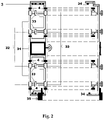
- FIG. 2 illustrates a schematic view of the solar panel cleaning system according to present invention.
- FIG. 3 illustrates a block diagram of control unit-I according to present invention.
- FIG. 4 illustrates a block diagram of control unit-II according to present invention.
- FIG. 5 illustrates a block diagram of control system according to another embodiment of the present invention.
- FIG. 1 illustrates the comprehensive view of the solar panel cleaning system according to present invention.
- the solar panel cleaning system which is marked herein by reference numeral ( 1 ) (enumerated in FIGS. 1 and 2 ), operates on parallel rows of solar panels.
- the parallel rows of the solar panels, called herein solar panel array, are marked herein by reference numerals ( 2 ).
- the solar panel cleaning system ( 1 ) mainly comprises a structure ( 3 ) being supported through a plurality of driving wheels ( 4 ) that carry said structure ( 3 ) bidirectionally movable along the length of the solar panel row and in the width direction of the solar panel width during cleaning operation.
- Said structure ( 3 ) is equipped with plurality of cleaning brushes ( 31 ) being rotated during cleaning operation for removing dirt, debris and dust from the surface of the solar panels ( 2 ), a wheel drive motor ( 32 ) for operating driving wheels ( 2 ) for carrying said structure ( 3 ), a brush drive motor ( 33 ) for rotational actuation of the cleaning brushes ( 31 ), a supporting wheel ( 34 ), an operating unit (shown in FIG. 3 ) for performing movement of the structure ( 3 ) at pre-defined time interval and for driving the cleaning brushes ( 31 ) and the driving wheels ( 4 ) and for controlling the speed of said wheel motor ( 32 ) and the brush motor ( 33 ).
- the system of the present invention may also comprise a blower ( 35 ) for generating air stream to blow off the dirt, debris and dust.
- the structure ( 3 ) after performing cleaning operations of solar panel ( 2 ), the structure ( 3 ) will be rest on platform (A, B) located adjacent to the both end of the solar pane array, in non-operating condition so that area of the system do not occupy the surface of solar panel ( 2 ).
- a sensor ( 5 ) preferably but not limited to, ultrasonic sensor, is mounted. It is to be understood that in some embodiment, the sensor may be mounted on the platform (A, B) instead of the structure. In present invention, the system will rest on platform (A, B) in any circumstances after completing cleaning process.
- said operating unit comprises a timer ( 36 ) (shown in FIG. 1 ) wherein time for actuation of the cleaning and driving operation is defined, a control unit-I ( 37 ) and a control unit-II ( 38 ) as shown in FIG. 3 and FIG. 4 respectively.
- a timer 36
- control unit-I 37
- control unit-II 38
- said control unit-I ( 37 ) mainly comprising a SMPS ( 371 ) for generating regulated power supply (DC 12V), an chicken UNO R3 microcontroller unit ( 372 ) connected in serial communication mode to reciprocally share data and operated through the power supply being supplied from the SMPS ( 371 ), said microcontroller ( 372 ) is configured to interface with the ultrasonic sensors ( 5 ) that detect the presence of the system by incident wave and reflected wave back from object and accordingly they transmit the signals to the microcontroller ( 372 ) to operate the driving wheels ( 4 ) into the forward and reverse direction.
- Said control unit-I ( 37 ) further comprises a RF transmitter ( 373 ) that transmits the pulse generated by the microcontroller ( 372 ) to the control unit-II ( 38 ) in the manner described below.
- said control unit-II ( 38 ) comprises a SMPS ( 381 ) for generating regulated power supply (DC 12V), a RF receiver ( 382 ) for receiving pulse transmitted by the RF transmitter ( 372 ), a motor controlling unit ( 383 ) having a wheel motor driver and a brush motor driver for controlling the rotating direction of the motors according to the pulse received by the RF receiver ( 382 ).
- the system will rest on the platform (A) or (B).
- the time for initiating the cleaning operation will be set into the timer ( 36 ).
- the timer ( 36 ) enables the power supply to provide the motor and brush driver and the micro-controller.
- said micro-controller operates the wheel motor ( 32 ) through motor driver.
- Said wheel motor ( 32 ) enables the driving wheels ( 4 ) to start moving on the surface of the solar panel ( 2 ).
- the ultrasonic sensor ( 5 ) will sense the system reaching on that platform.
- the ultrasonic sensor ( 5 ) After sensing the presence of the system, the ultrasonic sensor ( 5 ) sends the signal to the micro controller ( 372 ). After analysis of the signal, the signal is wirelessly transmitted to the RF receiver ( 382 ) and then transmitted to the motor control unit ( 383 ). Said motor control unit ( 383 ) change the direction of the motors ( 32 ) and accordingly the driving wheels ( 4 ) also start to operate in reverse mode. Along with the movement of the driving wheels ( 4 ), the cleaning brushes ( 31 ) will also start to rotate to clean the solar panel ( 2 ). The signals of ultrasonic sensors ( 5 ) coming from different platforms are written into the microcontroller ( 372 ) and accordingly the system travels on forward and reverse direction. It is to be noted that said brushes may also be stationary rather than rotating. Further, after particular time, the timer ( 36 ) will cut off the power supply to the system so that the system will stop working after cleaning the solar panel ( 2 ).
- said structure is equipped with solar panel ( 55 , 56 ) (shown in FIG. 5 ) on upper surface thereof such that maximum solar light impinge on the surface of these solar panels ( 55 , 56 ).
- solar panel ( 55 , 56 ) shown in FIG. 5
- the numbers of solar panel ( 55 , 56 ) shown in FIG. 5 are for the sake of understanding only. It is within the scope of present invention to utilize one or any numbers of solar panel as per requirement.
- the configuration of operating unit is shown in FIG. 5 .
- said operating unit comprises a motor driver ( 51 ) and a brush driver ( 52 ) that control the speed of the wheel motor ( 32 ) and the brush motor ( 33 ) respectively.
- Said operating unit also comprises a timer ( 53 ) and a micro-controller ( 54 ).
- said timer ( 53 ) and the micro controller ( 54 ) gets electric supply from the solar panel ( 55 ) through a solar charge controller ( 55 a ).
- the wheel motor driver ( 51 ) and the brush motor driver ( 52 ) receive required supply from the solar panel ( 56 ) through a solar charge controller ( 56 a ).
- the power supply from the solar panel ( 55 , 56 ) is stored into the battery ( 55 b , 56 b ) respectively.
- Said solar panels ( 55 , 56 ) keep charge the batteries ( 55 b , 56 b ) through solar charge controller ( 55 a , 56 a ).
- the timer ( 53 ) and the microcontroller ( 54 ) are operated by the power supply being supplied by the battery ( 55 b ).
- Said batteries ( 55 b , 56 b ) are also charged by solar energy through the solar panel by solar charge controller ( 55 a , 56 a ).
- Said solar controllers ( 55 a , 56 a ) are employed for the sake of safety that prevent the damages in battery from the over charging.
- the system will rest on the platform (A) or (B).
- the timer ( 53 ) When the timer ( 53 ) is actuated for pre-define time interval, it enable the power supply from solar operated battery ( 55 b ) to provide to the micro-controller ( 54 ).
- Said microcontroller ( 54 ) sends signal to the wheel motor driver ( 51 ) and the brush motor driver ( 52 ).
- said motor driver ( 51 ) and the brush driver ( 52 ) actuate the wheel motor ( 32 ) and the brush motor ( 33 ) respectively by providing power supply from the solar operated battery ( 56 b ).
- the system starts to run from platform A to platform B and simultaneously clean the solar panel arrays with the help of the rotation of brushes ( 31 ).
- the motor ( 32 , 33 ) will be started at low r.p.m.
- the r.p.m. of the motor ( 32 , 33 ) will be increased.
- said ultrasonic sensor ( 5 ) sends signal to the microcontroller ( 54 ).
- said microcontroller ( 54 ) receives signal, it sends command to wheel motor driver ( 51 ) and brush motor driver ( 52 ) and accordingly, said drivers will reduce the r.p.m. of the wheel motor ( 32 ) and the brush motor ( 33 ).
- the r.p.m. of the wheel motor ( 32 ) and brush motor ( 33 ) will be approximate at Zero. Then, the system will be operated in reverse mode and will run in the manner as described above (From platform B to A). During the translation of the system according to present invention on the solar panel array, the wearing parts of the motor ( 32 , 33 ) will not be damaged during change in rotating direction due to avoidance of jerk experience during sudden changes in rotating direction of the motors.
- the back and forth movements of the system from platform A to B and platform B to A are defined in the microcontroller. After completion of defined round from platform A to B and platform B to A, said micro-controller stops the functions of the motors ( 32 , 33 ). Then, after particular time, the timer ( 53 ) will cut off the power supply to the system so that the system will stop working after cleaning the solar panel.
- said structure ( 1 ) is also equipped with an emergency stop button for keeping the structure moving from platform A to platform B and vice versa in case of failure of ultrasonic sensor or any other failure situation.
- an arrangement of vertical member is provided on the platform (A) and (B).
- Said emergency stop buttons are located on the body of structure ( 1 ) in such a way that when structure ( 3 ) reaches to the plate, said stop button gets pressed by said vertical member if sensor doesn't send signal and then it moves in opposite direction.
- the brushes are also provided on the platform (A) and (B) for cleaning the surface of the solar panel ( 55 , 56 ). Said solar panel ( 55 , 56 ) will get automatically cleaned through these brushes during translation of the structure between platforms (A, B).
Landscapes
- Engineering & Computer Science (AREA)
- Physics & Mathematics (AREA)
- Life Sciences & Earth Sciences (AREA)
- Sustainable Development (AREA)
- Sustainable Energy (AREA)
- Thermal Sciences (AREA)
- Chemical & Material Sciences (AREA)
- Combustion & Propulsion (AREA)
- Mechanical Engineering (AREA)
- General Engineering & Computer Science (AREA)
- Cleaning In General (AREA)
- Photovoltaic Devices (AREA)
Abstract
Description
- Solar Panel Cleaning System (1)
- Solar Panel (2)
- Structure (3)
- Cleaning brush (31)
- Wheel drive motor (32)
- Brush drive motor (33)
- Supporting wheel (34)
- Blower (35)
- Timer (36)
- Control unit-I (37)
- SMPS (371)
- R3 microcontroller unit (372)
- RF transmitter (373)
- Control unit-II (38)
- SMPS (381)
- RF receiver (382)
- Motor controlling unit (383)
- Motor driver (51)
- Brush driver (52)
- Timer (53)
- Micro-controller (54)
- Solar panel (55, 56)
- Solar charge controller (55 a, 56 a)
- Battery (55 b, 56 b)
- Wheels (4)
- Ultrasonic sensor (5)
Claims (5)
Applications Claiming Priority (5)
| Application Number | Priority Date | Filing Date | Title |
|---|---|---|---|
| IN201721047112 | 2017-12-28 | ||
| IN201721047112 | 2017-12-28 | ||
| IN201821016142 | 2018-04-28 | ||
| IN201821016142 | 2018-04-28 | ||
| PCT/IN2018/050886 WO2019130352A1 (en) | 2017-12-28 | 2018-12-27 | Self powered and timer based solar panel cleaning system |
Publications (2)
| Publication Number | Publication Date |
|---|---|
| US20200355402A1 US20200355402A1 (en) | 2020-11-12 |
| US11466901B2 true US11466901B2 (en) | 2022-10-11 |
Family
ID=67066750
Family Applications (1)
| Application Number | Title | Priority Date | Filing Date |
|---|---|---|---|
| US16/958,580 Active 2039-02-13 US11466901B2 (en) | 2017-12-28 | 2018-12-27 | Self powered and timer based solar panel cleaning system |
Country Status (6)
| Country | Link |
|---|---|
| US (1) | US11466901B2 (en) |
| EP (1) | EP3732406B1 (en) |
| CN (1) | CN111868456A (en) |
| ES (1) | ES2965511T3 (en) |
| MX (1) | MX2020006784A (en) |
| WO (1) | WO2019130352A1 (en) |
Families Citing this family (2)
| Publication number | Priority date | Publication date | Assignee | Title |
|---|---|---|---|---|
| USD938114S1 (en) * | 2019-03-22 | 2021-12-07 | Sungrow Power Supply Co., Ltd. | Intelligent cleaning robot |
| CN113198765B (en) * | 2021-05-03 | 2024-06-07 | 深圳怪虫机器人有限公司 | Photovoltaic cleaning robot capable of automatically returning and continuing |
Citations (14)
| Publication number | Priority date | Publication date | Assignee | Title |
|---|---|---|---|---|
| DE102010025845A1 (en) | 2009-07-03 | 2011-01-05 | Franz Ehleuter | Solar system cleaner |
| EP2549199A1 (en) * | 2011-07-21 | 2013-01-23 | Giancarlo Cannizzo | Automatic cleaning device for a solar panel |
| US20130206173A1 (en) * | 2010-08-24 | 2013-08-15 | Jelle Zijlstra | Mobile cleaning device for solar panels |
| US20140150816A1 (en) * | 2012-10-01 | 2014-06-05 | Scott Potter | Automatic solar power surface-cleaner |
| KR101417992B1 (en) * | 2014-02-26 | 2014-08-07 | 인테그라글로벌 주식회사 | Apparatus for cleaning and coling solar panel |
| CN105149253A (en) | 2015-06-24 | 2015-12-16 | 中国科学院合肥物质科学研究院 | Solar cell panel cleaning device and system |
| US20170194898A1 (en) * | 2016-01-05 | 2017-07-06 | Ecoppia Scientific Ltd. | Solar panel cleaning system capable of cleaning a plurality of solar arrays |
| TR201711064A2 (en) * | 2017-07-27 | 2017-10-23 | Bilal Karaman | AUTONOMOUS PHOTOVOLTAIC PANEL SURFACE CLEANING ROBOT FOR SOLAR ENERGY POWER PLANTS |
| US20170329347A1 (en) * | 2016-05-11 | 2017-11-16 | Brain Corporation | Systems and methods for training a robot to autonomously travel a route |
| US20180087908A1 (en) * | 2016-07-08 | 2018-03-29 | Alion Energy, Inc. | Systems, methods, and vehicles for maintaining solar panels |
| US20180212558A1 (en) * | 2017-01-26 | 2018-07-26 | Evermore United S.A. | Waterless cleaning system and method for solar trackers using an autonomous robot |
| US20180241343A1 (en) * | 2016-09-21 | 2018-08-23 | Suzhou Radiant Photovoltaic Technology Co., Ltd. | Solar panel cleaning robot |
| US20190214940A1 (en) * | 2016-07-08 | 2019-07-11 | Henry Ouri Allouche | Method and apparatus for cleaning surfaces |
| US20190245481A1 (en) * | 2015-08-24 | 2019-08-08 | Saudi Arabian Oil Company | Front-Heavy Dust Cleaning Vehicle |
Family Cites Families (6)
| Publication number | Priority date | Publication date | Assignee | Title |
|---|---|---|---|---|
| CN101567398B (en) * | 2008-04-24 | 2013-01-09 | 鸿富锦精密工业(深圳)有限公司 | Solar panel automatic cleaning system and method |
| JP5686271B2 (en) * | 2012-12-25 | 2015-03-18 | 株式会社未来機械 | Self-propelled cleaning robot |
| ES1080004Y (en) * | 2013-04-10 | 2013-08-26 | Ceballos Francisco Luque | Automatic solar panel cleaning device. |
| CN104464284A (en) * | 2014-11-17 | 2015-03-25 | 成都和音科技有限公司 | Energy-saving detector long in service life |
| CN104467646B (en) * | 2014-11-24 | 2017-03-29 | 韩国海 | Solar panel automatic cleaning device and its transhipment connection machine |
| CN204810221U (en) * | 2015-05-22 | 2015-11-25 | 苏州科沃斯商用机器人有限公司 | Solar cell panel self -cleaning system |
-
2018
- 2018-12-27 US US16/958,580 patent/US11466901B2/en active Active
- 2018-12-27 MX MX2020006784A patent/MX2020006784A/en unknown
- 2018-12-27 ES ES18897645T patent/ES2965511T3/en active Active
- 2018-12-27 EP EP18897645.0A patent/EP3732406B1/en active Active
- 2018-12-27 WO PCT/IN2018/050886 patent/WO2019130352A1/en not_active Ceased
- 2018-12-27 CN CN201880084304.7A patent/CN111868456A/en active Pending
Patent Citations (15)
| Publication number | Priority date | Publication date | Assignee | Title |
|---|---|---|---|---|
| DE102010025845A1 (en) | 2009-07-03 | 2011-01-05 | Franz Ehleuter | Solar system cleaner |
| US20130206173A1 (en) * | 2010-08-24 | 2013-08-15 | Jelle Zijlstra | Mobile cleaning device for solar panels |
| EP2549199A1 (en) * | 2011-07-21 | 2013-01-23 | Giancarlo Cannizzo | Automatic cleaning device for a solar panel |
| US20140150816A1 (en) * | 2012-10-01 | 2014-06-05 | Scott Potter | Automatic solar power surface-cleaner |
| KR101417992B1 (en) * | 2014-02-26 | 2014-08-07 | 인테그라글로벌 주식회사 | Apparatus for cleaning and coling solar panel |
| CN105149253B (en) * | 2015-06-24 | 2017-06-13 | 中国科学院合肥物质科学研究院 | Solar panel clearing apparatus and system |
| CN105149253A (en) | 2015-06-24 | 2015-12-16 | 中国科学院合肥物质科学研究院 | Solar cell panel cleaning device and system |
| US20190245481A1 (en) * | 2015-08-24 | 2019-08-08 | Saudi Arabian Oil Company | Front-Heavy Dust Cleaning Vehicle |
| US20170194898A1 (en) * | 2016-01-05 | 2017-07-06 | Ecoppia Scientific Ltd. | Solar panel cleaning system capable of cleaning a plurality of solar arrays |
| US20170329347A1 (en) * | 2016-05-11 | 2017-11-16 | Brain Corporation | Systems and methods for training a robot to autonomously travel a route |
| US20180087908A1 (en) * | 2016-07-08 | 2018-03-29 | Alion Energy, Inc. | Systems, methods, and vehicles for maintaining solar panels |
| US20190214940A1 (en) * | 2016-07-08 | 2019-07-11 | Henry Ouri Allouche | Method and apparatus for cleaning surfaces |
| US20180241343A1 (en) * | 2016-09-21 | 2018-08-23 | Suzhou Radiant Photovoltaic Technology Co., Ltd. | Solar panel cleaning robot |
| US20180212558A1 (en) * | 2017-01-26 | 2018-07-26 | Evermore United S.A. | Waterless cleaning system and method for solar trackers using an autonomous robot |
| TR201711064A2 (en) * | 2017-07-27 | 2017-10-23 | Bilal Karaman | AUTONOMOUS PHOTOVOLTAIC PANEL SURFACE CLEANING ROBOT FOR SOLAR ENERGY POWER PLANTS |
Non-Patent Citations (3)
| Title |
|---|
| CN105149253B_Translated_Description (Year: 2022). * |
| PCT International Search Report and Written Opinion PCT/IN2018/050886 dated Apr. 11, 2019; 8 pages. |
| TR_201711064_Translated_Description (Year: 2022). * |
Also Published As
| Publication number | Publication date |
|---|---|
| CN111868456A (en) | 2020-10-30 |
| EP3732406B1 (en) | 2023-08-30 |
| ES2965511T3 (en) | 2024-04-15 |
| EP3732406A4 (en) | 2021-09-22 |
| US20200355402A1 (en) | 2020-11-12 |
| EP3732406A1 (en) | 2020-11-04 |
| WO2019130352A1 (en) | 2019-07-04 |
| MX2020006784A (en) | 2020-11-09 |
Similar Documents
| Publication | Publication Date | Title |
|---|---|---|
| US11489487B2 (en) | Robotic solar panel cleaning system | |
| Manju et al. | Automatic solar panel cleaning system | |
| CN103866728B (en) | Commercial robot scrubber | |
| KR20210106448A (en) | Robot vacuum cleaner and its cleaning method | |
| US11466901B2 (en) | Self powered and timer based solar panel cleaning system | |
| CN107080500B (en) | Intelligent cleaning robot system | |
| WO2019012402A1 (en) | Robotic waterless cleaning and inspection system with an assistive robotic docking train system and method | |
| CN103406292A (en) | Photovoltaic module cleaning robot | |
| CN105703703A (en) | Automatic cleaning device for solar cell panel | |
| KR20230000576A (en) | apparatus for cleaning photovoltaic module | |
| CN104826825A (en) | Surface cleaning device for solar cell module | |
| CN208508873U (en) | A kind of photovoltaic module Intelligent sweeping machine device people | |
| CN107008675A (en) | Photovoltaic panel automatic flushing device | |
| CN211209649U (en) | Wisdom photovoltaic power generation device | |
| CN109194274A (en) | A kind of control system and its control method of photovoltaic clearing apparatus | |
| CN217659663U (en) | Base station robot and intelligent machine system | |
| CN219678401U (en) | Snow removal truck for photovoltaic panel | |
| CN208783466U (en) | A kind of Novel pig house cleaning robot | |
| CN205817831U (en) | Photovoltaic intelligent O&M robot | |
| CN213836485U (en) | Automatic start-stop unmanned solar road surface cleaning vehicle | |
| CN205817832U (en) | Photovoltaic intelligent dedusting snow removal machine people | |
| CN208044353U (en) | SCM Based photovoltaic array dedusting control system | |
| CN110952488B (en) | An automatic control circuit for sweeping discs that can automatically adapt to various road conditions | |
| CN114983297A (en) | Base station robot and intelligent machine system | |
| CN105996887B (en) | Remote-controlled double-side window-cleaning robot control system and control method |
Legal Events
| Date | Code | Title | Description |
|---|---|---|---|
| FEPP | Fee payment procedure |
Free format text: ENTITY STATUS SET TO UNDISCOUNTED (ORIGINAL EVENT CODE: BIG.); ENTITY STATUS OF PATENT OWNER: SMALL ENTITY |
|
| FEPP | Fee payment procedure |
Free format text: ENTITY STATUS SET TO SMALL (ORIGINAL EVENT CODE: SMAL); ENTITY STATUS OF PATENT OWNER: SMALL ENTITY |
|
| AS | Assignment |
Owner name: WEISMACHER ECO PRIVATE LIMITED, INDIA Free format text: ASSIGNMENT OF ASSIGNORS INTEREST;ASSIGNORS:ACHARYA, RAJESHKUMAR HARIPRASAD;GHADIALI, YUSUF NAZMUDDIN;REEL/FRAME:053566/0501 Effective date: 20200729 |
|
| STPP | Information on status: patent application and granting procedure in general |
Free format text: DOCKETED NEW CASE - READY FOR EXAMINATION |
|
| STPP | Information on status: patent application and granting procedure in general |
Free format text: NON FINAL ACTION MAILED |
|
| STPP | Information on status: patent application and granting procedure in general |
Free format text: RESPONSE TO NON-FINAL OFFICE ACTION ENTERED AND FORWARDED TO EXAMINER |
|
| STPP | Information on status: patent application and granting procedure in general |
Free format text: NOTICE OF ALLOWANCE MAILED -- APPLICATION RECEIVED IN OFFICE OF PUBLICATIONS |
|
| STPP | Information on status: patent application and granting procedure in general |
Free format text: PUBLICATIONS -- ISSUE FEE PAYMENT VERIFIED |
|
| STCF | Information on status: patent grant |
Free format text: PATENTED CASE |