US11460456B2 - Gas sensor - Google Patents
Gas sensor Download PDFInfo
- Publication number
- US11460456B2 US11460456B2 US17/038,110 US202017038110A US11460456B2 US 11460456 B2 US11460456 B2 US 11460456B2 US 202017038110 A US202017038110 A US 202017038110A US 11460456 B2 US11460456 B2 US 11460456B2
- Authority
- US
- United States
- Prior art keywords
- protective cover
- gas
- sensor element
- element chamber
- sensor
- Prior art date
- Legal status (The legal status is an assumption and is not a legal conclusion. Google has not performed a legal analysis and makes no representation as to the accuracy of the status listed.)
- Active, expires
Links
Images


Classifications
-
- G—PHYSICS
- G01—MEASURING; TESTING
- G01N—INVESTIGATING OR ANALYSING MATERIALS BY DETERMINING THEIR CHEMICAL OR PHYSICAL PROPERTIES
- G01N33/00—Investigating or analysing materials by specific methods not covered by groups G01N1/00 - G01N31/00
- G01N33/0004—Gaseous mixtures, e.g. polluted air
-
- G—PHYSICS
- G01—MEASURING; TESTING
- G01N—INVESTIGATING OR ANALYSING MATERIALS BY DETERMINING THEIR CHEMICAL OR PHYSICAL PROPERTIES
- G01N27/00—Investigating or analysing materials by the use of electric, electrochemical, or magnetic means
- G01N27/26—Investigating or analysing materials by the use of electric, electrochemical, or magnetic means by investigating electrochemical variables; by using electrolysis or electrophoresis
- G01N27/403—Cells and electrode assemblies
- G01N27/406—Cells and probes with solid electrolytes
- G01N27/407—Cells and probes with solid electrolytes for investigating or analysing gases
- G01N27/4077—Means for protecting the electrolyte or the electrodes
-
- G—PHYSICS
- G01—MEASURING; TESTING
- G01N—INVESTIGATING OR ANALYSING MATERIALS BY DETERMINING THEIR CHEMICAL OR PHYSICAL PROPERTIES
- G01N27/00—Investigating or analysing materials by the use of electric, electrochemical, or magnetic means
- G01N27/26—Investigating or analysing materials by the use of electric, electrochemical, or magnetic means by investigating electrochemical variables; by using electrolysis or electrophoresis
- G01N27/416—Systems
- G01N27/417—Systems using cells, i.e. more than one cell and probes with solid electrolytes
- G01N27/419—Measuring voltages or currents with a combination of oxygen pumping cells and oxygen concentration cells
-
- G—PHYSICS
- G01—MEASURING; TESTING
- G01N—INVESTIGATING OR ANALYSING MATERIALS BY DETERMINING THEIR CHEMICAL OR PHYSICAL PROPERTIES
- G01N33/00—Investigating or analysing materials by specific methods not covered by groups G01N1/00 - G01N31/00
- G01N33/0004—Gaseous mixtures, e.g. polluted air
- G01N33/0009—General constructional details of gas analysers, e.g. portable test equipment
- G01N33/0011—Sample conditioning
- G01N33/0021—Sample conditioning involving the use of a carrier gas for transport to the sensor
-
- G—PHYSICS
- G01—MEASURING; TESTING
- G01N—INVESTIGATING OR ANALYSING MATERIALS BY DETERMINING THEIR CHEMICAL OR PHYSICAL PROPERTIES
- G01N33/00—Investigating or analysing materials by specific methods not covered by groups G01N1/00 - G01N31/00
- G01N33/0004—Gaseous mixtures, e.g. polluted air
- G01N33/0009—General constructional details of gas analysers, e.g. portable test equipment
- G01N33/0027—General constructional details of gas analysers, e.g. portable test equipment concerning the detector
- G01N33/0036—General constructional details of gas analysers, e.g. portable test equipment concerning the detector specially adapted to detect a particular component
- G01N33/0037—NOx
-
- G—PHYSICS
- G01—MEASURING; TESTING
- G01N—INVESTIGATING OR ANALYSING MATERIALS BY DETERMINING THEIR CHEMICAL OR PHYSICAL PROPERTIES
- G01N33/00—Investigating or analysing materials by specific methods not covered by groups G01N1/00 - G01N31/00
- G01N33/0004—Gaseous mixtures, e.g. polluted air
- G01N33/0009—General constructional details of gas analysers, e.g. portable test equipment
- G01N33/0027—General constructional details of gas analysers, e.g. portable test equipment concerning the detector
- G01N33/0036—General constructional details of gas analysers, e.g. portable test equipment concerning the detector specially adapted to detect a particular component
- G01N33/0054—Ammonia
Definitions
- the present invention relates to a gas sensor.
- a gas sensor that detects the concentration of predetermined gas, such as NOx and oxygen, in measurement-object gas, such as exhaust gas of an automobile, is known.
- the gas sensor includes, for example, a sensor element, an inner protective cover having a sensor element chamber in which the sensor element is placed and having an element chamber inlet and an element chamber outlet, and an outer protective cover having an outer inlet and an outer outlet.
- Measurement-object gas reaches the sensor element chamber from the outside of the gas sensor through the outer inlet and the element chamber inlet, and is partially introduced into the sensor element. Measurement-object gas having reached the sensor element chamber is emitted to the outside through the element chamber outlet and the outer outlet thereafter.
- the present invention is made to solve such inconvenience, and it is a main object to suppress exposure of a sensor element to water.
- the present invention employs the following manner to achieve the above-described main object.
- a gas sensor of the present invention includes:
- a sensor element having a gas inlet port that introduces measurement-object gas and capable of detecting a specific gas concentration of the measurement-object gas having flowed in from the gas inlet port;
- a cylindrical inner protective cover having inside a sensor element chamber in which a tip end of the sensor element and the gas inlet port are disposed, and having one or more element chamber inlets that are inlets to the sensor element chamber and one or more element chamber outlets that are outlets from the sensor element chamber;
- a cylindrical outer protective cover disposed outside the inner protective cover and having one or more outer inlets that are inlets for the measurement-object gas from an outside and one or more outer outlets that are outlets for the measurement-object gas to the outside, wherein
- the outer protective cover and the inner protective cover form, as spaces between the outer protective cover and the inner protective cover, an inlet-side gas flow channel that functions as a flow channel for the measurement-object gas between the one or more outer inlets and the one or more element chamber inlets and an outlet-side gas flow channel that functions as a flow channel for the measurement-object gas between the one or more outer outlets and the one or more element chamber outlets and that does not directly communicate with the inlet-side gas flow channel,
- a cross section parallel to a width direction of the sensor element along a central axis of the sensor element is a width-direction cross section
- a direction parallel to an axial direction of the inner protective cover from a rear end of the sensor element toward the tip end of the sensor element is a downward direction
- a direction from the tip end of the sensor element toward the rear end of the sensor element is an upward direction
- a minimum distance XW in the width-direction cross section between the sensor element and a portion of the inner protective cover on a side in the downward direction with respect to the one or more element chamber inlets is greater than or equal to 2.64 mm
- the one or more element chamber outlets and the one or more outer outlets are disposed in such a positional relation that, when imaginary light parallel to an axial direction of the outer outlet is irradiated from the outside of the outer protective cover to the outer outlet, the imaginary light does not reach an inside of the sensor element chamber, and a minimum flow channel width Y of the outlet-side gas flow channel is greater than or equal to 0.67 mm and less than or equal to 2.60 mm.
- the gap between the sensor element and the portion of the inner protective cover on the side in the downward direction with respect to the one or more element chamber inlets widens, so, even when water accumulated in the inner protective cover flies off, the water is less likely to reach the sensor element.
- the one or more element chamber outlets and the one or more outer outlets are disposed in such a positional relation that, when imaginary light parallel to the axial direction of the outer outlet is irradiated from the outside of the outer protective cover to the outer outlet, the imaginary light does not reach the inside of the sensor element chamber. For this reason, it is possible to suppress direct entry of water from the one or more outer outlets of the gas sensor to the sensor element chamber.
- the minimum flow channel width Y of the outlet-side gas flow channel is greater than or equal to 0.67 mm, water drained from the sensor element chamber to the outlet-side gas flow channel through the one or more element chamber outlets is easy to reach the one or more outer outlets. For this reason, water is easy to be drained to the outside of the gas sensor.
- the minimum flow channel width Y of the outlet-side gas flow channel is less than or equal to 2.60 mm, even when water enters the outlet-side gas flow channel from the outside of the gas sensor to the outlet-side gas flow channel through the one or more outer outlets, the water is less likely to reach the one or more element chamber outlets.
- minimum flow channel width Y means a flow channel width in a plane having the narrowest flow channel width (also referred to as narrow width plane) among planes that are surrounded by at least one of the outer protective cover and the inner protective cover and through which measurement-object gas that flows from the one or more element chamber outlets to the one or more outer outlets definitely passes.
- the narrow width plane is, for example, an annular plane sandwiched by the outer protective cover and the inner protective cover.
- the narrow width plane may be a single plane or may be two or more planes present continuously or discretely.
- the minimum flow channel width Y is greater than or equal to 0.67 mm and less than or equal to 2.60 mm” may be translated into the phrase “the diameter of a largest sphere that can reach the outer outlet from the element chamber outlet is greater than or equal to 0.67 mm and less than or equal to 2.60 mm”.
- the gas sensor When, for example, the gas sensor is used at an angle with respect to a vertical direction, water tends to accumulate near a connection portion with the first portion larger in inside diameter than the second portion in the stepped portion; however, when the stepped portion is disposed not on a side in the upward direction but on the side in the downward direction with respect to the tip end surface of the sensor element, the distance between the connection portion and the sensor element increases, so it is possible to further suppress exposure of the sensor element to water.
- the inner protective cover may include a bottomed cylindrical tip end portion, and the one or more element chamber outlets may be disposed not at a bottom portion of the tip end portion but at a side portion of the tip end portion.
- the one or more element chamber outlets are disposed not at the bottom portion but at the side portion, even when gas spontaneously flows in from the outside of the one or more element chamber outlets, the flow of gas is less likely to concentrate in a direction toward the sensor element, so it is possible to suppress a situation in which water reaches the sensor element over gas flow.
- the one or more outer outlets may be disposed at a bottom portion of the outer protective cover. When the one or more outer outlets are disposed at the bottom portion while the one or more element chamber outlets are disposed at the side portion, it is possible to further suppress entry of water from the outside of the gas sensor into the sensor element chamber.
- the minimum distance XW may be greater than or equal to 2.80 mm.
- the minimum flow channel width Y may be greater than or equal to 0.80 mm and less than or equal to 2.00 mm.
- the minimum flow channel width Y of the outlet-side gas flow channel is greater than or equal to 0.80 mm, water drained from the sensor element chamber further tends to be drained to the outside of the gas sensor.
- the minimum flow channel width Y of the outlet-side gas flow channel is less than or equal to 2.00 mm, even when water enters from the outside of the gas sensor through the one or more outer outlets, the water is further less likely to reach the one or more element chamber outlets.
- the inner protective cover may have a first member and a second member, the first member and the second member may form the one or more element chamber inlets as a gap between the first member and the second member, and, in each of the one or more element chamber inlets, an element-side opening that is an opening adjacent to the sensor element chamber may be open in the downward direction.
- the phrase “the element-side opening is open in the downward direction” includes a case where the one or more element chamber inlets are open parallel to the downward direction and a case where the one or more element chamber inlets are open at an angle with respect to the downward direction so as to approach the sensor element toward a lower side.
- the first member may have a first cylinder portion surrounding the sensor element
- the second member may have a second cylinder portion larger in diameter than the first cylinder portion
- the one or more element chamber inlets may be a cylindrical gap between an outer peripheral surface of the first cylinder portion and an inner peripheral surface of the second cylinder portion.
- FIG. 1 is a schematic diagram of a state where a gas sensor 100 is attached to a pipe 20 .
- FIG. 2 is a cross-sectional view taken along the line A-A in FIG. 1 .
- FIG. 3 is a cross-sectional view taken along the line B-B in FIG. 2 .
- FIG. 4 is a cross-sectional view taken along the line C-C in FIG. 3 .
- FIG. 5 is a cross-sectional view of an outer protective cover 140 , taken along the line C-C in FIG. 3 .
- FIG. 6 is a view along the arrow D in FIG. 3 .
- FIG. 7 is a partially enlarged view of FIG. 3 .
- FIG. 8 is a longitudinal sectional view of a gas sensor 200 of a modification.
- FIG. 1 is a schematic diagram of a state where a gas sensor 100 is attached to a pipe 20 .
- FIG. 2 is a cross-sectional view taken along the line A-A in FIG. 1 .
- FIG. 3 is a cross-sectional view taken along the line B-B in FIG. 2 .
- FIG. 4 is a cross-sectional view taken along the line C-C in FIG. 3 .
- FIG. 5 is a cross-sectional view of an outer protective cover 140 , taken along the line C-C in FIG. 3 .
- FIG. 5 corresponds to a diagram excluding a first cylinder portion 134 , a second cylinder portion 136 , a tip end portion 138 , and a sensor element 110 from FIG. 4 .
- FIG. 6 is a view along the arrow D in FIG. 3 .
- FIG. 7 is a partially enlarged view of FIG. 3 .
- a direction parallel to an axial direction of a protective cover 120 from a tip end of the sensor element 110 toward a rear end of the sensor element 110 (upward direction in FIG. 3 and FIG. 7 ) is defined as upward direction
- a direction parallel to the axial direction of the protective cover 120 from the rear end of the sensor element 110 toward the tip end of the sensor element 110 is defined as downward direction.
- the gas sensor 100 is attached inside the pipe 20 that is an exhaust pathway from an engine of a vehicle and is configured to detect a specific gas concentration that is the concentration of at least any one specific gas of gas components, such as NOx, ammonia, and O 2 , contained in exhaust gas as measurement-object gas emitted from the engine.
- the gas sensor 100 is fixed to the pipe 20 in a state where a central axis of the gas sensor 100 is perpendicular to the flow of measurement-object gas in the pipe 20 .
- the gas sensor 100 may be fixed to the pipe 20 in a state where the central axis of the gas sensor 100 is perpendicular to the flow of measurement-object gas in the pipe 20 and inclined at a predetermined angle (for example, any angle included in the range of 45° to 80°) with respect to a vertical direction.
- a predetermined angle for example, any angle included in the range of 45° to 80°
- the sensor element 110 is an element having a narrow long planar shape and has an element body 110 b with such a structure that a plurality of oxygen-ion-conductive solid electrolyte layers made of zirconia (ZrO 2 ) or the like is laminated.
- the element body 110 b has a gas inlet port 111 that introduces therein measurement-object gas and is configured to be capable of detecting a specific gas concentration of measurement-object gas having flowed in from the gas inlet port 111 .
- the gas inlet port 111 is open at the tip end surface of the element body 110 b (the lower surface of the element body 110 b in FIG. 3 ).
- the sensor element 110 includes inside a heater that plays a role in temperature adjustment to retain temperature by heating the sensor element 110 .
- the structure of the sensor element 110 and the principle of detecting a specific gas concentration are known and are described in, for example, Japanese Unexamined Patent Application Publication No. 2008-164411.
- the tip end (the lower end in FIG. 3 ) and gas inlet port 111 of the sensor element 110 are disposed inside the sensor element chamber 124 .
- a direction from the rear end of the sensor element 110 toward the tip end of the sensor element 110 (downward direction) is also referred to as tip end direction.
- the porous protective layer 110 a is made of, for example, a porous material, such as alumina porous material, zirconia porous material, spinel porous material, cordierite porous material, titania porous material, and magnesia porous material.
- the porous protective layer 110 a may be formed by, for example, plasma spraying, screen printing, dipping, or the like.
- the porous protective layer 110 a also covers the gas inlet port 111 ; however, since the porous protective layer 110 a is a porous material, measurement-object gas is able to flow through the inside of the porous protective layer 110 a and reach the gas inlet port 111 .
- the thickness of the porous protective layer 110 a is, for example, 100 ⁇ m to 700 ⁇ m.
- the protective cover 120 is disposed so as to surround the sensor element 110 .
- the protective cover 120 has a bottomed cylindrical inner protective cover 130 that covers the tip end of the sensor element 110 and a bottomed outer protective cover 140 that covers the inner protective cover 130 .
- An inlet-side gas flow channel 152 and an outlet-side gas flow channel 156 are formed as spaces surrounded by the inner protective cover 130 and the outer protective cover 140
- a sensor element chamber 124 is formed as a space surrounded by the inner protective cover 130 .
- the central axes of the gas sensor 100 , the sensor element 110 , the inner protective cover 130 , and the outer protective cover 140 are coaxial with one another.
- the protective cover 120 is made of metal (for example, stainless steel, such as SUS310S).
- the second member 135 has a second cylinder portion 136 larger in diameter than the first cylinder portion 134 , a bottomed cylindrical tip end portion 138 located on a side in the tip end direction (downward direction) of the sensor element 110 with respect to the second cylinder portion 136 , and a connection portion 137 connecting the lower end of the second cylinder portion 136 and the tip end portion 138 .
- the connection portion 137 has a third cylinder portion 137 a smaller in diameter than the second cylinder portion 136 and larger in diameter than the tip end portion 138 , a first stepped portion 137 b connecting the second cylinder portion 136 and the third cylinder portion 137 a , and a second stepped portion 137 c connecting the third cylinder portion 137 a and the tip end portion 138 .
- the first stepped portion 137 b and the second stepped portion 137 c both are disposed on a side in the downward direction with respect to the tip end surface 110 c of the sensor element 110 .
- the tip end portion 138 has a side portion 138 d and a bottom portion 138 e .
- the tip end portion 138 has one or more element chamber outlets 138 a that communicate with the sensor element chamber 124 and the outlet-side gas flow channel 156 and that are outlets for measurement-object gas from the sensor element chamber 124 .
- the element chamber outlets 138 a include a plurality of (four in the present embodiment) horizontal holes 138 b formed at equal intervals at the side portion 138 d .
- the element chamber outlets 138 a are not disposed at the bottom portion 138 e of the tip end portion 138 .
- the diameter of each element chamber outlet 138 a is, for example, 0.5 mm to 2.6 mm. In the present embodiment, the diameter of each of the plurality of horizontal holes 138 b is set to the same value.
- the element chamber outlets 138 a are formed on a side in the tip end direction (downward direction) of the sensor element 110 with respect to the gas inlet port 111 .
- the element chamber outlets 138 a are located away (in the downward direction) from the gas inlet port 111 when viewed from the rear end of the sensor element 110 (the upper end (not shown) of the sensor element 110 in FIG. 3 ).
- the second member 135 may be fixed by forming the outside diameter of the tip end side (lower end side) of the third cylinder portion 137 a so as to be slightly larger than the inside diameter of the tip end portion 146 of the outer protective cover 140 and press-fitting the tip end portion of the third cylinder portion 137 a into the tip end portion 146 .
- a plurality of protruding portions 136 a that protrude toward the outer peripheral surface of the first cylinder portion 134 and that are in contact with the outer peripheral surface are formed on the inner peripheral surface of the second cylinder portion 136 .
- three protruding portions 136 a are provided and are disposed equally on the inner peripheral surface of the second cylinder portion 136 along the circumferential direction.
- Each protruding portion 136 a is formed in a substantially semi-spherical shape.
- the protruding portions 136 a press the outer peripheral surface of the first cylinder portion 134 radially inward. With this configuration, it is possible to further reliably fix the positional relation between the first cylinder portion 134 and the second cylinder portion 136 with the protruding portions 136 a .
- the number of the protruding portions 136 a is not limited to three and may be two or may be more than or equal to four. Because fixing of the first cylinder portion 134 to the second cylinder portion 136 tends to be stable, it is desirable that the number of the protruding portions 136 a be more than or equal to three.
- the inner protective cover 130 forms an element chamber inlet 127 (see FIG. 3 , FIG. 4 , and FIG. 7 ) that is a gap between the first member 131 and the second member 135 and that is an inlet for measurement-object gas into the sensor element chamber 124 .
- the element chamber inlet 127 is formed as a cylindrical gap (gas flow channel) between the outer peripheral surface of the first cylinder portion 134 and the inner peripheral surface of the second cylinder portion 136 .
- the element chamber inlet 127 has an outer opening 128 that is an opening adjacent to the inlet-side gas flow channel 152 that is a space in which the outer inlets 144 a are disposed, and an element-side opening 129 that is an opening adjacent to the sensor element chamber 124 that is a space in which the gas inlet port 111 is disposed.
- the outer opening 128 is formed on the rear end side (upper side) of the sensor element 110 with respect to the element-side opening 129 . Therefore, in the pathway of measurement-object gas from the outer inlets 144 a to the gas inlet port 111 , the element chamber inlet 127 is a flow channel from the rear end side (upper side) of the sensor element 110 toward the tip end side (lower side).
- the element chamber inlet 127 is a flow channel parallel to a rear end-tip end direction (a flow channel parallel to the up-down direction) of the sensor element 110 .
- the inner protective cover 130 is disposed such that, in the width-direction cross section parallel to the width direction of the sensor element 110 along the central axis of the sensor element 110 , the minimum distance XW between the sensor element 110 and the portion that is on the side in the downward direction (on the side in the tip end direction) with respect to the element chamber inlet 127 is greater than or equal to 2.64 mm.
- the distance (the length of an imaginary line 160 shown in FIG. 7 ) between the third cylinder portion 137 a -side end of the first stepped portion 137 b and the tip end-side edge of the sensor element 110 is the minimum distance XW
- the inner protective cover 130 is disposed such that the minimum distance XW is greater than or equal to 2.64 mm.
- the portion on the side in the downward direction with respect to the element chamber inlet 127 means a portion on the side in the downward direction with respect to an imaginary plane P including the element-side opening 129 that is the lower end of the element chamber inlet 127 , and does not include a portion in the imaginary plane P. Therefore, the portion on the side in the downward direction with respect to the element chamber inlet 127 does not include the first member 131 .
- the outer protective cover 140 has a cylindrical body portion 143 and a bottomed cylindrical tip end portion 146 smaller in inside diameter than the body portion 143 .
- the body portion 143 has a side portion 143 a having a side surface along a central axis direction (up-down direction) of the outer protective cover 140 , and a stepped portion 143 b that is a bottom portion of the body portion 143 and that connects the side portion 143 a and the tip end portion 146 .
- the central axes of the body portion 143 and the tip end portion 146 all are the same as the central axis of the inner protective cover 130 .
- a portion around the upper end in the body portion 143 is in contact with the housing 102 and the large-diameter portion 132 on its inner peripheral surface.
- the outer protective cover 140 is fixed to the housing 102 .
- the body portion 143 is located so as to cover the outer circumference of the large-diameter portion 132 , the first cylinder portion 134 , and the second cylinder portion 136 .
- the tip end portion 146 is located so as to cover the tip end portion 138 , and the inner peripheral surface is in contact with the outer peripheral surface of the third cylinder portion 137 a .
- the outer protective cover 140 has one or more (in the present embodiment, multiple and, specifically, 12) outer inlets 144 a that are formed in the body portion 143 and that are inlets for measurement-object gas from the outside, and one or more outer outlets 147 a that are formed in the tip end portion 146 and that are outlets for measurement-object gas to the outside.
- the outer inlets 144 a are holes that communicate with the outer side (outside) of the outer protective cover 140 and the inlet-side gas flow channel 152 .
- the outer inlets 144 a include a plurality of (in the present embodiment, six) horizontal holes 144 b formed at equal intervals in the side portion 143 a , and a plurality of (in the present embodiment, six) vertical holes 144 c formed at equal intervals in the stepped portion 143 b (see FIG. 3 to FIG. 6 ).
- the outer inlets 144 a (horizontal holes 144 b and vertical holes 144 c ) are holes perforated in a circular shape.
- the diameter of each of the 12 outer inlets 144 a is, for example, 0.5 mm to 2 mm.
- each outer inlet 144 a may be less than or equal to 1.5 mm.
- the diameter of each of the plurality of horizontal holes 144 b is the same value, and the diameter of each of the plurality of vertical holes 144 c is the same value.
- the diameter of each horizontal hole 144 b is greater than the diameter of each vertical hole 144 c .
- the outer inlets 144 a are formed such that the horizontal holes 144 b and the vertical holes 144 c are alternately located at equal intervals along the circumferential direction of the outer protective cover 140 .
- an angle formed between a line connecting the center of each horizontal hole 144 b and the central axis of the outer protective cover 140 and a line connecting the center of the vertical hole 144 c adjacent to that horizontal hole 144 b and the central axis of the outer protective cover 140 in FIG. 4 and FIG. 5 is 30° (360°/12).
- the outer outlets 147 a are holes that communicate with the outer side (outside) of the outer protective cover 140 and the outlet-side gas flow channel 156 .
- the outer outlets 147 a include one or more (in the present embodiment, one) vertical holes 147 c formed at the center of the bottom portion 146 b of the tip end portion 146 (see FIG. 3 , FIG. 5 , and FIG. 6 ).
- the outer outlet 147 a (here, the vertical hole 147 c ) is a hole perforated in a circular shape.
- the diameter of the outer outlet 147 a is, for example, 0.5 mm to 2.5 mm.
- the diameter of the outer outlet 147 a may be less than or equal to 1.5 mm.
- the diameter of the vertical hole 147 c is set to a value greater than the diameter of the horizontal hole 144 b or the vertical hole 144 c .
- the outer outlet 147 a is disposed by adjusting the positional relation with the element chamber outlet 138 a such that, when imaginary light parallel to the axial direction of the outer outlet 147 a from the outside of the outer protective cover 140 to the outer outlet 147 a , the imaginary light does not reach the inside of the sensor element chamber 124 .
- the imaginary light strikes the bottom portion 138 e of the inner protective cover 130 , the imaginary light does not reach the inside of the sensor element chamber 124 .
- the outer outlet 147 a is disposed not at the side portion 146 a but at the bottom portion 146 b such that the outer outlet 147 a and the element chamber outlet 138 a are open in different directions.
- the outer outlet 147 a different from the outer inlets 144 a , is not disposed at the side portion of the outer protective cover 140 (here, the side portion 146 a of the tip end portion 146 ).
- the element chamber outlet 138 a is disposed not at the bottom portion 138 e but at the side portion 138 d so as to deviate from a region where the above-described imaginary light strikes.
- the element chamber outlets 138 a and the outer outlet 147 a may have a diameter larger than or equal to the minimum flow channel width Y or a diameter larger than the minimum flow channel width Y.
- Measurement-object gas that flows in the pipe 20 initially passes through at least any one of the plurality of outer inlets 144 a (the horizontal holes 144 b and the vertical holes 144 c ) and flows into the inlet-side gas flow channel 152 . Subsequently, measurement-object gas flows from the inlet-side gas flow channel 152 into the element chamber inlet 127 via the outer opening 128 , passes through the element chamber inlet 127 , flows out from the element-side opening 129 , and flows into the sensor element chamber 124 .
- the sensor element 110 When measurement-object gas reaches the gas inlet port 111 and flows into the inside of the sensor element 110 , the sensor element 110 generates an electrical signal (voltage or current) according to a specific gas concentration in the measurement-object gas, and the specific gas concentration is detected based on the electrical signal.
- Measurement-object gas in the sensor element chamber 124 flows into the outlet-side gas flow channel 156 through at least any one of the element chamber outlets 138 a (here, the horizontal holes 138 b ) and flows out from there to the outside through the outer outlet 147 a (here, the vertical hole 147 c ).
- the output of a heater inside the sensor element 110 is controlled by a controller (not shown) such that the sensor element 110 is maintained at a predetermined temperature.
- condensed water may be produced inside the pipe 20 through which exhaust gas or the like of an automobile flows.
- Such condensed water may enter the inside of the outer protective cover 140 from the outer inlets 144 a or the outer outlet 147 a as a result of flow of the above-described measurement-object gas, spontaneous gas flow at engine startup, or the like and further enter the sensor element chamber 124 from the element chamber inlet 127 or the element chamber outlets 138 a .
- Water having entered the sensor element chamber 124 flows in the downward direction under its own weight, so water tends to accumulate in an area on the side in the downward direction with respect to the element chamber inlet 127 in the inner protective cover 130 .
- a minimum distance (also referred to as minimum distance XH) between the sensor element 110 and a portion on the side in the downward direction with respect to the element chamber inlet 127 in a thickness-direction cross section (cross section perpendicular to the E-E cross section in FIG. 4 along the central axis of the sensor element 110 ) is greater than 2.64 mm.
- the element chamber outlets 138 a and the outer outlet 147 a are disposed in such a positional relation that, when imaginary light parallel to the axial direction of the outer outlet 147 a is irradiated from the outside of the outer protective cover 140 to the outer outlet 147 a , the imaginary light does not reach the inside of the sensor element chamber 124 . For this reason, it is possible to reduce direct entry of water from the outer outlet 147 a of the gas sensor 100 to the sensor element chamber 124 .
- the minimum flow channel width Y of the outlet-side gas flow channel 156 is greater than or equal to 0.67 mm, water drained from the sensor element chamber 124 to the outlet-side gas flow channel 156 through the element chamber outlets 138 a is easy to reach the outer outlet 147 a side. For this reason, water tends to be drained to the outside of the gas sensor 100 .
- the minimum flow channel width Y of the outlet-side gas flow channel 156 is less than or equal to 2.60 mm, even when water enters the outlet-side gas flow channel 156 from the outside of the gas sensor 100 through the outer outlet 147 a , the water is less likely to reach the element chamber outlets 138 a .
- the gas sensor 100 of the present embodiment is capable of reducing exposure of the sensor element 110 to water. It is desirable that the minimum distance XW be greater than or equal to 2.80 mm. It is desirable that the minimum flow channel width Y be greater than or equal to 0.80 mm and less than or equal to 2.00 mm.
- the inner protective cover 130 has a step structure made up of the cylindrical second cylinder portion 136 , the third cylinder portion 137 a (which corresponds to the second portion when the second cylinder portion 136 is regarded as the first portion of the present invention), and the first stepped portion 137 b (which corresponds to the stepped portion when the second cylinder portion 136 is regarded as the first portion of the present invention) connecting the second cylinder portion 136 and the third cylinder portion 137 a .
- a gas sensor is mostly used in a state where the central axis is inclined with respect to the vertical direction, and, in that case, water tends to accumulate near the connection portion with the first portion in the stepped portions. Therefore, the first stepped portion 137 b and the second stepped portion 137 c are disposed not on the side in the upward direction but on the side in the downward direction with respect to the tip end surface 110 c of the sensor element 110 such that the distance between the connection portion and the sensor element 110 increases. For this reason, exposure of the sensor element 110 to water is further suppressed.
- the minimum distance XW between the inner protective cover 130 and the sensor element 110 is greater than or equal to 2.64 mm on the side in the downward direction with respect to the element chamber inlet 127 .
- the element chamber outlets 138 a and the outer outlet 147 a are disposed in such a positional relation that, when imaginary light parallel to the axial direction of the outer outlet 147 a is irradiated from the outside of the outer protective cover 140 to the outer outlet 147 a , the imaginary light does not reach the inside of the sensor element chamber 124 .
- the minimum flow channel width Y of the outlet-side gas flow channel 156 is greater than or equal to 0.67 mm and less than or equal to 2.60 mm. For this reason, exposure of the sensor element 110 to water is suppressed.
- the element chamber outlets 138 a are disposed not at the bottom portion 138 e of the tip end portion 138 but at the side portion 138 d . Therefore, even when gas spontaneously flows in from the outside of the element chamber outlets 138 a , flow of gas is less likely to concentrate in the direction toward the sensor element 110 , and water is less likely to reach the sensor element 110 over gas flow. Not only the element chamber outlets 138 a are disposed at the side portion 138 d but also the outer outlet 147 a is disposed at the bottom portion 146 b of the outer protective cover 140 . Therefore, water is further less likely to enter the sensor element chamber 124 from the outside of the gas sensor 100 .
- the minimum distance XW is greater than or equal to 2.80 mm
- the sensor element 110 is further less likely to be exposed to water.
- the minimum flow channel width Y is greater than or equal to 0.80 mm
- water drained from the sensor element chamber 124 tends to be drained to the outside of the gas sensor 100 .
- the minimum flow channel width Y is less than or equal to 2.00 mm, even when water enters from the outside of the gas sensor 100 through the outer outlet 147 a , the water is further less likely to reach the element chamber outlets 138 a.
- the first member 131 and the second member 135 form the element chamber inlet 127 such that the element-side opening 129 is open in the downward direction.
- the inner protective cover 130 has two stepped portions (the first stepped portion 137 b and the second stepped portion 137 c ).
- the inner protective cover 130 does not need to have a stepped portion or the number of the stepped portions may be one or three or more.
- the second stepped portion 137 c may be omitted as in the case of a gas sensor 200 of FIG. 8 (described later), or the first stepped portion 137 b may be omitted as in the case of a gas sensor 400 of FIG. 10 (described later).
- the distance between the first stepped portion 137 b and the sensor element 110 is set to the minimum distance XW.
- the distance between the second stepped portion 137 c and the sensor element 110 may be set to the minimum distance XW, or the distance between the sensor element 110 and a portion other than the stepped portions may be set to the minimum distance XW.
- a through-hole provided at a tapered portion (for example, a tapered portion 238 d (described later)) may be formed.
- the element chamber outlets 138 a , the outer inlets 144 a , and the outer outlet 147 a each are not limited to a hole and may be a gap between a plurality of members that make up the protective cover 120 as in the case of the element chamber inlet 127 , and it is sufficient that the number of each is one or more.
- the positional relation between the element chamber outlet 238 a and the outer outlets 247 a are adjusted such that, when imaginary light parallel to the axial direction of each outer outlet 247 a from the outside of the outer protective cover 240 to the outer outlet 247 a , the imaginary light does not reach the inside of the sensor element chamber 124 .
- the element chamber outlet 238 a is disposed so as to be open perpendicular to the horizontal holes 247 b at the bottom portion 238 e disposed on the side in the upward direction with respect to the upper end of the horizontal holes 247 b so as to deviate from a region where imaginary light irradiated from the horizontal holes 247 b in the outer outlets 247 a strikes.
- an imaginary annular plane 262 between an annular portion around the element chamber outlet 238 a of the bottom portion 238 e of the tip end portion 238 of the inner protective cover 230 and a portion facing the annular portion in the bottom portion 246 b of the outer protective cover 240 is the minimum flow channel width Y and the minimum flow channel width Y is greater than or equal to 0.67 mm and less than or equal to 2.60 mm.
- the imaginary annular plane 262 has a cylindrical shape.
- the minimum distance XW is greater than or equal to 2.64 mm
- the element chamber outlet 238 a and the outer outlets 247 a are disposed in the above-described positional relation, and the minimum flow channel width Y is greater than or equal to 0.67 mm and less than or equal to 2.60 mm, exposure of the sensor element 110 to water is suppressed.
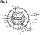
- the element chamber inlet 127 is a cylindrical gap between the outer peripheral surface of the first cylinder portion 134 and the inner peripheral surface of the second cylinder portion 136 ; however, the configuration is not limited thereto.
- a recessed portion may be formed on at least one of the outer peripheral surface of the first cylinder portion and the inner peripheral surface of the second cylinder portion, and the element chamber inlet may be a gap formed by the recessed portion between the first cylinder portion and the second cylinder portion.
- FIG. 9 is a cross-sectional view showing an element chamber inlet 327 of a modification.
- like reference signs are assigned to the same components as those of the gas sensor 100 , and the detailed description thereof is omitted.
- the element chamber inlet 127 is a flow channel parallel to the rear end-tip end direction of the sensor element 110 (a flow channel parallel to the up-down direction in FIG. 3 ).
- the element chamber inlet 127 may be a flow channel inclined at an angle with respect to the up-down direction so as to approach the sensor element 110 toward the downward side.
- FIG. 10 is a longitudinal sectional view of a gas sensor 400 of a modification in this case.
- like reference signs are assigned to the same components as those of the gas sensor 100 , and the detailed description thereof is omitted.
- a protective cover 420 of the gas sensor 400 includes an inner protective cover 430 instead of the inner protective cover 130 .
- the inner protective cover 430 includes a first member 431 and a second member 435 .
- the first member 431 as compared to the first member 131 , includes a cylindrical body portion 434 a and a cylindrical first cylinder portion 434 b that reduces in diameter toward the lower side, instead of the first cylinder portion 134 .
- the first cylinder portion 434 b is connected to the body portion 434 a at its upper end portion.
- the second member 435 as compared to the second member 135 , includes a cylindrical second cylinder portion 436 that reduces in diameter toward the lower side, instead of the second cylinder portion 136 , and includes a connection portion 437 from which the first stepped portion 137 b is omitted, instead of the connection portion 137 .
- the element-side opening 429 is open at an angle with respect to the up-down direction so as to approach the sensor element 110 toward the lower side (see the enlarged view in FIG. 10 ). Therefore, the portion on the side in the downward direction with respect to the element chamber inlet 427 represents a portion on the side in the downward direction with respect to an imaginary plane P including the lower end of the element-side opening 429 . Therefore, the portion on the side in the downward direction with respect to the element chamber inlet 427 does not include the first member 431 .
- the orientation of the opening of the element-side opening 429 is the axial direction of the opening, which is determined based on the outer peripheral surface of the first cylinder portion 434 b and the inner peripheral surface of the second cylinder portion 436 around the opening.
- An opening plane of the element-side opening 429 is a plane perpendicular to the axial direction of the opening.
- the sensor element 110 is disposed at a position other than a region that is an imaginary extension of the element chamber inlet 427 from the element-side opening 429 .
- the minimum distance XW is greater than or equal to 2.64 mm
- the element chamber outlets 138 a and the outer outlets 147 a are disposed in the above-described positional relation, and the minimum flow channel width Y is greater than or equal to 0.67 mm and less than or equal to 2.60 mm, exposure of the sensor element 110 to water is suppressed.
- the inner protective cover 130 includes two members, that is, the first member 131 and the second member 135 .
- the first member 131 and the second member 135 may be an integrated member.
- the sensor element 110 has a rectangular shape in cross section perpendicular to the central axis.
- the cross section perpendicular to the central axis may have a square shape or a circular shape.
- the minimum distance XW is greater than or equal to 2.64 mm in the width-direction cross section
- the minimum distance XH is also greater than or equal to 2.64 mm.
- the gas inlet port 111 is open at the tip end surface of the element body 110 b (the lower surface of the element body 110 b in FIG. 3 ); however, the configuration is not limited thereto.
- the gas inlet port 111 may be open at the side surface of the element body 110 b (the surface, extending in the up-down direction, of the element body 110 b in FIG. 4 ).
- the sensor element 110 includes the porous protective layer 110 a .
- the sensor element 110 does not need to include the porous protective layer 110 a .
- the lower surface of the element body 110 b is the tip end surface of the sensor element 110 .
- Example 1 The gas sensor 100 shown in FIG. 3 to FIG. 7 was assumed as Example 1.
- the minimum distance XW was set to 3.24 mm
- the minimum flow channel width Y was set to 1.06 mm.
- Example 4 was configured similarly to the gas sensor 100 of Example 1 except that the position of the sensor element 110 was moved to the side in the downward direction with respect to the protective cover 120 such that the minimum distance XW was 2.64 mm and the length of the side portion 138 d was shortened such that the minimum flow channel width Y was 2.60 mm.
- the gas sensor 200 shown in FIG. 8 was set as Comparative Example 1.
- the minimum distance XW was set to 2.64 mm
- the minimum flow channel width Y was set to 2.88 mm.
- the position of the sensor element 110 relative to the protective cover 220 was moved to the side in the downward direction as compared to FIG. 8
- the first stepped portion 137 b was provided on the upper side with respect to the tip end surface 110 c of the sensor element 110
- the third cylinder portion 137 a -side end of the first stepped portion 137 b was located in an imaginary plane including the tip end surface 110 c of the sensor element 110 .
- Comparative Example 2 was configured similarly to the gas sensor 100 of Example 3 except that the length of the side portion 138 d was extended such that the minimum flow channel width Y was 0.48 mm.
- Example 3 was configured similarly to the gas sensor 100 of Example 1 except that the position of the sensor element 110 was moved in the downward direction with respect to the protective cover 120 such that the minimum distance XW was 2.46 mm.
- the water exposure test apparatus described in Japanese Unexamined Patent Application Publication No. 2019-158615 was used to evaluate the amount of water exposure.
- the water exposure test apparatus includes a pipe having inside a flow channel for gas and disposed horizontally and linearly, a blower provided upstream of the pipe, a pressure fluctuation generator provided downstream side of the pipe, and a chamber that is part of the pipe between the blower and the pressure fluctuation generator and to which a gas sensor is attached.
- a vibration generator that adds vibrations to the chamber is connected to the chamber.
- a gas sensor was placed inside the chamber of the water exposure test apparatus in a state where the central axis of the gas sensor was perpendicular to the axis of the pipe and inclined at 10° with respect to the horizontal direction. Then, a predetermined amount of moisture was supplied into the pipe between the blower and the chamber. Subsequently, gas (the atmosphere) was supplied into the pipe by using the blower, the pressure of gas was caused to fluctuate by using the pressure fluctuation generator, and vibrations were added to the chamber by the vibration generator. Thus, moisture supplied into the pipe flies off toward the gas sensor placed inside the chamber by the gas that fluctuates in pressure.
- a heater incorporated in a sensor element was driven to control a heater power such that the temperature of the sensor element was set to a predetermined target value between 100° C. and 200° C.
- the amount of water exposure of the sensor element in each gas sensor was obtained by applying a controlled value of heater power at this time to a pre-derived relationship between a heater power and an amount of water exposure.
- the minimum distance XW be greater than or equal to 2.64 mm and it is more desirable that the minimum distance XW be greater than or equal to 2.80 mm. It is also inferred that it is desirable that the minimum flow channel width Y be greater than or equal to 0.67 mm and less than or equal to 2.60 mm and it is more desirable that the minimum flow channel width Y be greater than or equal to 0.80 mm and less than or equal to 2.00 mm.
Landscapes
- Chemical & Material Sciences (AREA)
- Life Sciences & Earth Sciences (AREA)
- Health & Medical Sciences (AREA)
- Engineering & Computer Science (AREA)
- Analytical Chemistry (AREA)
- General Physics & Mathematics (AREA)
- Pathology (AREA)
- Physics & Mathematics (AREA)
- Immunology (AREA)
- Biochemistry (AREA)
- General Health & Medical Sciences (AREA)
- Combustion & Propulsion (AREA)
- Food Science & Technology (AREA)
- Medicinal Chemistry (AREA)
- Molecular Biology (AREA)
- Chemical Kinetics & Catalysis (AREA)
- Electrochemistry (AREA)
- Measuring Oxygen Concentration In Cells (AREA)
Applications Claiming Priority (3)
| Application Number | Priority Date | Filing Date | Title |
|---|---|---|---|
| JP2019-183076 | 2019-10-03 | ||
| JP2019183076A JP7261718B2 (ja) | 2019-10-03 | 2019-10-03 | ガスセンサ |
| JPJP2019-183076 | 2019-10-03 |
Publications (2)
| Publication Number | Publication Date |
|---|---|
| US20210102927A1 US20210102927A1 (en) | 2021-04-08 |
| US11460456B2 true US11460456B2 (en) | 2022-10-04 |
Family
ID=74876056
Family Applications (1)
| Application Number | Title | Priority Date | Filing Date |
|---|---|---|---|
| US17/038,110 Active 2040-10-03 US11460456B2 (en) | 2019-10-03 | 2020-09-30 | Gas sensor |
Country Status (4)
| Country | Link |
|---|---|
| US (1) | US11460456B2 (https=) |
| JP (1) | JP7261718B2 (https=) |
| CN (1) | CN112611837A (https=) |
| DE (1) | DE102020005911A1 (https=) |
Families Citing this family (1)
| Publication number | Priority date | Publication date | Assignee | Title |
|---|---|---|---|---|
| JP7239434B2 (ja) * | 2019-10-03 | 2023-03-14 | 日本碍子株式会社 | ガスセンサ及び保護カバー |
Citations (7)
| Publication number | Priority date | Publication date | Assignee | Title |
|---|---|---|---|---|
| US20080156644A1 (en) | 2006-12-28 | 2008-07-03 | Ngk Insulators, Ltd. | NOx-DECOMPOSING ELECTRODE AND METHOD FOR PRODUCING NOx SENSOR |
| JP2009158615A (ja) | 2007-12-25 | 2009-07-16 | Furukawa Electric Co Ltd:The | 多層プリント基板およびその製造方法 |
| US7708869B2 (en) * | 2006-09-21 | 2010-05-04 | Denso Corporation | Gas sensor |
| US20150101394A1 (en) * | 2013-10-16 | 2015-04-16 | Ngk Spark Plug Co., Ltd. | Gas sensor |
| US20160076919A1 (en) * | 2013-05-31 | 2016-03-17 | Ngk Insulators, Ltd. | Gas sensor |
| US20170363596A1 (en) * | 2016-06-17 | 2017-12-21 | Ngk Insulators, Ltd. | Gas sensor |
| US20190285596A1 (en) | 2018-03-13 | 2019-09-19 | Ngk Insulators, Ltd. | Wetting test apparatus and method for gas sensor |
Family Cites Families (11)
| Publication number | Priority date | Publication date | Assignee | Title |
|---|---|---|---|---|
| JP4426084B2 (ja) * | 2000-11-22 | 2010-03-03 | 日本特殊陶業株式会社 | ガスセンサ |
| JP2011158262A (ja) * | 2010-01-29 | 2011-08-18 | Ngk Spark Plug Co Ltd | ガスセンサ |
| JP5396429B2 (ja) * | 2010-05-18 | 2014-01-22 | 日本碍子株式会社 | ガス濃度検出センサー |
| JP5890765B2 (ja) * | 2011-11-18 | 2016-03-22 | 日本碍子株式会社 | ガスセンサ |
| JP5993782B2 (ja) | 2012-04-17 | 2016-09-14 | 日本特殊陶業株式会社 | ガスセンサ |
| JP6047974B2 (ja) * | 2012-07-24 | 2016-12-21 | 三菱自動車工業株式会社 | ガスセンサの保護カバー構造 |
| CN203241368U (zh) * | 2013-03-08 | 2013-10-16 | 苏爱芳 | 气体传感器保护罩 |
| JP6269348B2 (ja) * | 2014-06-30 | 2018-01-31 | 株式会社デンソー | ガスセンサ |
| JP6654416B2 (ja) * | 2014-12-02 | 2020-02-26 | 日本碍子株式会社 | ガスセンサ |
| JP6740024B2 (ja) | 2016-06-17 | 2020-08-12 | 日本碍子株式会社 | ガスセンサ |
| JP6850556B2 (ja) * | 2016-06-17 | 2021-03-31 | 日本碍子株式会社 | ガスセンサ |
-
2019
- 2019-10-03 JP JP2019183076A patent/JP7261718B2/ja active Active
-
2020
- 2020-09-27 CN CN202011030936.0A patent/CN112611837A/zh active Pending
- 2020-09-28 DE DE102020005911.2A patent/DE102020005911A1/de active Pending
- 2020-09-30 US US17/038,110 patent/US11460456B2/en active Active
Patent Citations (9)
| Publication number | Priority date | Publication date | Assignee | Title |
|---|---|---|---|---|
| US7708869B2 (en) * | 2006-09-21 | 2010-05-04 | Denso Corporation | Gas sensor |
| US20080156644A1 (en) | 2006-12-28 | 2008-07-03 | Ngk Insulators, Ltd. | NOx-DECOMPOSING ELECTRODE AND METHOD FOR PRODUCING NOx SENSOR |
| JP2008164411A (ja) | 2006-12-28 | 2008-07-17 | Ngk Insulators Ltd | NOx分解電極及びNOxセンサの製造方法 |
| JP2009158615A (ja) | 2007-12-25 | 2009-07-16 | Furukawa Electric Co Ltd:The | 多層プリント基板およびその製造方法 |
| US20160076919A1 (en) * | 2013-05-31 | 2016-03-17 | Ngk Insulators, Ltd. | Gas sensor |
| US20150101394A1 (en) * | 2013-10-16 | 2015-04-16 | Ngk Spark Plug Co., Ltd. | Gas sensor |
| JP2015099142A (ja) | 2013-10-16 | 2015-05-28 | 日本特殊陶業株式会社 | ガスセンサ |
| US20170363596A1 (en) * | 2016-06-17 | 2017-12-21 | Ngk Insulators, Ltd. | Gas sensor |
| US20190285596A1 (en) | 2018-03-13 | 2019-09-19 | Ngk Insulators, Ltd. | Wetting test apparatus and method for gas sensor |
Non-Patent Citations (3)
| Title |
|---|
| Unexamined U.S. Appl. No. 17/038,099, filed Sep. 30, 2020. |
| Unexamined U.S. Appl. No. 17/038,103, filed Sep. 30, 2020. |
| Unexamined U.S. Appl. No. 17/038,109, filed Sep. 30, 2020. |
Also Published As
| Publication number | Publication date |
|---|---|
| US20210102927A1 (en) | 2021-04-08 |
| CN112611837A (zh) | 2021-04-06 |
| JP2021060220A (ja) | 2021-04-15 |
| DE102020005911A1 (de) | 2021-04-08 |
| JP7261718B2 (ja) | 2023-04-20 |
Similar Documents
| Publication | Publication Date | Title |
|---|---|---|
| US11226321B2 (en) | Gas sensor and protective cover | |
| US9952072B2 (en) | Gas sensor with flow channel formed by inner protective cover | |
| JP6740024B2 (ja) | ガスセンサ | |
| JP6740023B2 (ja) | ガスセンサ | |
| US8671740B2 (en) | Gas concentration detection sensor | |
| JP6276662B2 (ja) | ガスセンサ | |
| US7575663B2 (en) | Gas sensor | |
| JP4765865B2 (ja) | ガスセンサ | |
| US20210102915A1 (en) | Gas sensor and protective cover | |
| US10393694B2 (en) | Gas sensor | |
| US10775357B2 (en) | Gas sensor | |
| CN111417849A (zh) | 传感器装置 | |
| US11460456B2 (en) | Gas sensor | |
| US10775342B2 (en) | Gas sensor | |
| US11371975B2 (en) | Gas sensor and protective cover | |
| US10908116B2 (en) | Gas sensor | |
| JP3969124B2 (ja) | ガスセンサ | |
| JP7261717B2 (ja) | ガスセンサ | |
| JP2017223622A (ja) | ガスセンサ | |
| JP7821923B1 (ja) | ガスセンサ | |
| JP7821924B1 (ja) | ガスセンサ | |
| JP7804142B1 (ja) | ガスセンサ | |
| CN115104026B (zh) | 气体传感器 |
Legal Events
| Date | Code | Title | Description |
|---|---|---|---|
| FEPP | Fee payment procedure |
Free format text: ENTITY STATUS SET TO UNDISCOUNTED (ORIGINAL EVENT CODE: BIG.); ENTITY STATUS OF PATENT OWNER: LARGE ENTITY |
|
| AS | Assignment |
Owner name: NGK INSULATORS, LTD., JAPAN Free format text: ASSIGNMENT OF ASSIGNORS INTEREST;ASSIGNORS:TAKAHASHI, FUMIYA;OMORI, TAKESHI;SIGNING DATES FROM 20201006 TO 20201009;REEL/FRAME:054122/0794 |
|
| STPP | Information on status: patent application and granting procedure in general |
Free format text: APPLICATION DISPATCHED FROM PREEXAM, NOT YET DOCKETED |
|
| STPP | Information on status: patent application and granting procedure in general |
Free format text: DOCKETED NEW CASE - READY FOR EXAMINATION |
|
| STPP | Information on status: patent application and granting procedure in general |
Free format text: NON FINAL ACTION MAILED |
|
| STPP | Information on status: patent application and granting procedure in general |
Free format text: RESPONSE TO NON-FINAL OFFICE ACTION ENTERED AND FORWARDED TO EXAMINER |
|
| STPP | Information on status: patent application and granting procedure in general |
Free format text: NOTICE OF ALLOWANCE MAILED -- APPLICATION RECEIVED IN OFFICE OF PUBLICATIONS |
|
| STPP | Information on status: patent application and granting procedure in general |
Free format text: PUBLICATIONS -- ISSUE FEE PAYMENT RECEIVED |
|
| STPP | Information on status: patent application and granting procedure in general |
Free format text: PUBLICATIONS -- ISSUE FEE PAYMENT VERIFIED |
|
| STCF | Information on status: patent grant |
Free format text: PATENTED CASE |
|
| MAFP | Maintenance fee payment |
Free format text: PAYMENT OF MAINTENANCE FEE, 4TH YEAR, LARGE ENTITY (ORIGINAL EVENT CODE: M1551); ENTITY STATUS OF PATENT OWNER: LARGE ENTITY Year of fee payment: 4 |