US11387284B2 - OLED display substrate having a quantum dot color film layer, manufacturing method of the same, and display apparatus - Google Patents
OLED display substrate having a quantum dot color film layer, manufacturing method of the same, and display apparatus Download PDFInfo
- Publication number
- US11387284B2 US11387284B2 US16/639,025 US201916639025A US11387284B2 US 11387284 B2 US11387284 B2 US 11387284B2 US 201916639025 A US201916639025 A US 201916639025A US 11387284 B2 US11387284 B2 US 11387284B2
- Authority
- US
- United States
- Prior art keywords
- layer
- light
- blue
- emitting
- oled light
- Prior art date
- Legal status (The legal status is an assumption and is not a legal conclusion. Google has not performed a legal analysis and makes no representation as to the accuracy of the status listed.)
- Active, expires
Links
- 239000000758 substrate Substances 0.000 title claims description 125
- 239000002096 quantum dot Substances 0.000 title claims description 120
- 238000004519 manufacturing process Methods 0.000 title claims description 45
- 238000000034 method Methods 0.000 claims abstract description 32
- 238000002347 injection Methods 0.000 claims description 105
- 239000007924 injection Substances 0.000 claims description 105
- 239000010408 film Substances 0.000 claims description 61
- 230000005525 hole transport Effects 0.000 claims description 41
- 238000005538 encapsulation Methods 0.000 claims description 13
- 239000010409 thin film Substances 0.000 claims description 13
- 238000012544 monitoring process Methods 0.000 abstract 2
- 230000008569 process Effects 0.000 description 16
- 238000010586 diagram Methods 0.000 description 12
- 238000006243 chemical reaction Methods 0.000 description 6
- 239000003086 colorant Substances 0.000 description 6
- 238000000862 absorption spectrum Methods 0.000 description 4
- 238000000576 coating method Methods 0.000 description 4
- 239000000463 material Substances 0.000 description 4
- 238000000059 patterning Methods 0.000 description 4
- 238000001228 spectrum Methods 0.000 description 4
- 230000000694 effects Effects 0.000 description 2
- 238000000295 emission spectrum Methods 0.000 description 2
- 230000005284 excitation Effects 0.000 description 2
- 230000006872 improvement Effects 0.000 description 2
- 239000002159 nanocrystal Substances 0.000 description 2
- 239000002105 nanoparticle Substances 0.000 description 2
- 239000000243 solution Substances 0.000 description 2
- 230000009286 beneficial effect Effects 0.000 description 1
- 230000008859 change Effects 0.000 description 1
- 230000005684 electric field Effects 0.000 description 1
- 238000005516 engineering process Methods 0.000 description 1
- AMGQUBHHOARCQH-UHFFFAOYSA-N indium;oxotin Chemical compound [In].[Sn]=O AMGQUBHHOARCQH-UHFFFAOYSA-N 0.000 description 1
- 229910052751 metal Inorganic materials 0.000 description 1
- 239000002184 metal Substances 0.000 description 1
- 238000005215 recombination Methods 0.000 description 1
- 230000006798 recombination Effects 0.000 description 1
- 230000004044 response Effects 0.000 description 1
- 239000004065 semiconductor Substances 0.000 description 1
Images


Classifications
-
- H—ELECTRICITY
- H10—SEMICONDUCTOR DEVICES; ELECTRIC SOLID-STATE DEVICES NOT OTHERWISE PROVIDED FOR
- H10K—ORGANIC ELECTRIC SOLID-STATE DEVICES
- H10K59/00—Integrated devices, or assemblies of multiple devices, comprising at least one organic light-emitting element covered by group H10K50/00
- H10K59/30—Devices specially adapted for multicolour light emission
- H10K59/38—Devices specially adapted for multicolour light emission comprising colour filters or colour changing media [CCM]
-
- H—ELECTRICITY
- H10—SEMICONDUCTOR DEVICES; ELECTRIC SOLID-STATE DEVICES NOT OTHERWISE PROVIDED FOR
- H10K—ORGANIC ELECTRIC SOLID-STATE DEVICES
- H10K50/00—Organic light-emitting devices
- H10K50/10—OLEDs or polymer light-emitting diodes [PLED]
- H10K50/11—OLEDs or polymer light-emitting diodes [PLED] characterised by the electroluminescent [EL] layers
- H10K50/125—OLEDs or polymer light-emitting diodes [PLED] characterised by the electroluminescent [EL] layers specially adapted for multicolour light emission, e.g. for emitting white light
- H10K50/13—OLEDs or polymer light-emitting diodes [PLED] characterised by the electroluminescent [EL] layers specially adapted for multicolour light emission, e.g. for emitting white light comprising stacked EL layers within one EL unit
-
- H01L27/322—
-
- B—PERFORMING OPERATIONS; TRANSPORTING
- B82—NANOTECHNOLOGY
- B82Y—SPECIFIC USES OR APPLICATIONS OF NANOSTRUCTURES; MEASUREMENT OR ANALYSIS OF NANOSTRUCTURES; MANUFACTURE OR TREATMENT OF NANOSTRUCTURES
- B82Y30/00—Nanotechnology for materials or surface science, e.g. nanocomposites
-
- H01L51/5253—
-
- H01L51/5278—
-
- H01L51/56—
-
- H—ELECTRICITY
- H10—SEMICONDUCTOR DEVICES; ELECTRIC SOLID-STATE DEVICES NOT OTHERWISE PROVIDED FOR
- H10K—ORGANIC ELECTRIC SOLID-STATE DEVICES
- H10K50/00—Organic light-emitting devices
- H10K50/10—OLEDs or polymer light-emitting diodes [PLED]
- H10K50/11—OLEDs or polymer light-emitting diodes [PLED] characterised by the electroluminescent [EL] layers
- H10K50/115—OLEDs or polymer light-emitting diodes [PLED] characterised by the electroluminescent [EL] layers comprising active inorganic nanostructures, e.g. luminescent quantum dots
-
- H—ELECTRICITY
- H10—SEMICONDUCTOR DEVICES; ELECTRIC SOLID-STATE DEVICES NOT OTHERWISE PROVIDED FOR
- H10K—ORGANIC ELECTRIC SOLID-STATE DEVICES
- H10K50/00—Organic light-emitting devices
- H10K50/10—OLEDs or polymer light-emitting diodes [PLED]
- H10K50/19—Tandem OLEDs
-
- H—ELECTRICITY
- H10—SEMICONDUCTOR DEVICES; ELECTRIC SOLID-STATE DEVICES NOT OTHERWISE PROVIDED FOR
- H10K—ORGANIC ELECTRIC SOLID-STATE DEVICES
- H10K50/00—Organic light-emitting devices
- H10K50/80—Constructional details
- H10K50/84—Passivation; Containers; Encapsulations
- H10K50/844—Encapsulations
-
- H—ELECTRICITY
- H10—SEMICONDUCTOR DEVICES; ELECTRIC SOLID-STATE DEVICES NOT OTHERWISE PROVIDED FOR
- H10K—ORGANIC ELECTRIC SOLID-STATE DEVICES
- H10K71/00—Manufacture or treatment specially adapted for the organic devices covered by this subclass
-
- G—PHYSICS
- G02—OPTICS
- G02F—OPTICAL DEVICES OR ARRANGEMENTS FOR THE CONTROL OF LIGHT BY MODIFICATION OF THE OPTICAL PROPERTIES OF THE MEDIA OF THE ELEMENTS INVOLVED THEREIN; NON-LINEAR OPTICS; FREQUENCY-CHANGING OF LIGHT; OPTICAL LOGIC ELEMENTS; OPTICAL ANALOGUE/DIGITAL CONVERTERS
- G02F1/00—Devices or arrangements for the control of the intensity, colour, phase, polarisation or direction of light arriving from an independent light source, e.g. switching, gating or modulating; Non-linear optics
- G02F1/01—Devices or arrangements for the control of the intensity, colour, phase, polarisation or direction of light arriving from an independent light source, e.g. switching, gating or modulating; Non-linear optics for the control of the intensity, phase, polarisation or colour
- G02F1/13—Devices or arrangements for the control of the intensity, colour, phase, polarisation or direction of light arriving from an independent light source, e.g. switching, gating or modulating; Non-linear optics for the control of the intensity, phase, polarisation or colour based on liquid crystals, e.g. single liquid crystal display cells
- G02F1/133—Constructional arrangements; Operation of liquid crystal cells; Circuit arrangements
- G02F1/1333—Constructional arrangements; Manufacturing methods
- G02F1/1335—Structural association of cells with optical devices, e.g. polarisers or reflectors
- G02F1/133528—Polarisers
-
- H01L2251/5338—
-
- H—ELECTRICITY
- H01—ELECTRIC ELEMENTS
- H01L—SEMICONDUCTOR DEVICES NOT COVERED BY CLASS H10
- H01L27/00—Devices consisting of a plurality of semiconductor or other solid-state components formed in or on a common substrate
- H01L27/14—Devices consisting of a plurality of semiconductor or other solid-state components formed in or on a common substrate including semiconductor components sensitive to infrared radiation, light, electromagnetic radiation of shorter wavelength or corpuscular radiation and specially adapted either for the conversion of the energy of such radiation into electrical energy or for the control of electrical energy by such radiation
- H01L27/144—Devices controlled by radiation
- H01L27/146—Imager structures
- H01L27/14678—Contact-type imagers
-
- H01L27/3211—
-
- H01L27/323—
-
- H—ELECTRICITY
- H01—ELECTRIC ELEMENTS
- H01L—SEMICONDUCTOR DEVICES NOT COVERED BY CLASS H10
- H01L33/00—Semiconductor devices with at least one potential-jump barrier or surface barrier specially adapted for light emission; Processes or apparatus specially adapted for the manufacture or treatment thereof or of parts thereof; Details thereof
- H01L33/02—Semiconductor devices with at least one potential-jump barrier or surface barrier specially adapted for light emission; Processes or apparatus specially adapted for the manufacture or treatment thereof or of parts thereof; Details thereof characterised by the semiconductor bodies
- H01L33/04—Semiconductor devices with at least one potential-jump barrier or surface barrier specially adapted for light emission; Processes or apparatus specially adapted for the manufacture or treatment thereof or of parts thereof; Details thereof characterised by the semiconductor bodies with a quantum effect structure or superlattice, e.g. tunnel junction
- H01L33/06—Semiconductor devices with at least one potential-jump barrier or surface barrier specially adapted for light emission; Processes or apparatus specially adapted for the manufacture or treatment thereof or of parts thereof; Details thereof characterised by the semiconductor bodies with a quantum effect structure or superlattice, e.g. tunnel junction within the light emitting region, e.g. quantum confinement structure or tunnel barrier
-
- H—ELECTRICITY
- H01—ELECTRIC ELEMENTS
- H01L—SEMICONDUCTOR DEVICES NOT COVERED BY CLASS H10
- H01L33/00—Semiconductor devices with at least one potential-jump barrier or surface barrier specially adapted for light emission; Processes or apparatus specially adapted for the manufacture or treatment thereof or of parts thereof; Details thereof
- H01L33/44—Semiconductor devices with at least one potential-jump barrier or surface barrier specially adapted for light emission; Processes or apparatus specially adapted for the manufacture or treatment thereof or of parts thereof; Details thereof characterised by the coatings, e.g. passivation layer or anti-reflective coating
-
- H01L51/502—
-
- H01L51/5056—
-
- H01L51/5072—
-
- H01L51/5092—
-
- H01L51/5234—
-
- H01L51/5293—
-
- H—ELECTRICITY
- H10—SEMICONDUCTOR DEVICES; ELECTRIC SOLID-STATE DEVICES NOT OTHERWISE PROVIDED FOR
- H10K—ORGANIC ELECTRIC SOLID-STATE DEVICES
- H10K2102/00—Constructional details relating to the organic devices covered by this subclass
- H10K2102/301—Details of OLEDs
- H10K2102/311—Flexible OLED
-
- H—ELECTRICITY
- H10—SEMICONDUCTOR DEVICES; ELECTRIC SOLID-STATE DEVICES NOT OTHERWISE PROVIDED FOR
- H10K—ORGANIC ELECTRIC SOLID-STATE DEVICES
- H10K2102/00—Constructional details relating to the organic devices covered by this subclass
- H10K2102/301—Details of OLEDs
- H10K2102/331—Nanoparticles used in non-emissive layers, e.g. in packaging layer
-
- H—ELECTRICITY
- H10—SEMICONDUCTOR DEVICES; ELECTRIC SOLID-STATE DEVICES NOT OTHERWISE PROVIDED FOR
- H10K—ORGANIC ELECTRIC SOLID-STATE DEVICES
- H10K50/00—Organic light-emitting devices
- H10K50/10—OLEDs or polymer light-emitting diodes [PLED]
- H10K50/14—Carrier transporting layers
- H10K50/15—Hole transporting layers
-
- H—ELECTRICITY
- H10—SEMICONDUCTOR DEVICES; ELECTRIC SOLID-STATE DEVICES NOT OTHERWISE PROVIDED FOR
- H10K—ORGANIC ELECTRIC SOLID-STATE DEVICES
- H10K50/00—Organic light-emitting devices
- H10K50/10—OLEDs or polymer light-emitting diodes [PLED]
- H10K50/14—Carrier transporting layers
- H10K50/16—Electron transporting layers
-
- H—ELECTRICITY
- H10—SEMICONDUCTOR DEVICES; ELECTRIC SOLID-STATE DEVICES NOT OTHERWISE PROVIDED FOR
- H10K—ORGANIC ELECTRIC SOLID-STATE DEVICES
- H10K50/00—Organic light-emitting devices
- H10K50/10—OLEDs or polymer light-emitting diodes [PLED]
- H10K50/17—Carrier injection layers
- H10K50/171—Electron injection layers
-
- H—ELECTRICITY
- H10—SEMICONDUCTOR DEVICES; ELECTRIC SOLID-STATE DEVICES NOT OTHERWISE PROVIDED FOR
- H10K—ORGANIC ELECTRIC SOLID-STATE DEVICES
- H10K50/00—Organic light-emitting devices
- H10K50/80—Constructional details
- H10K50/805—Electrodes
- H10K50/82—Cathodes
- H10K50/828—Transparent cathodes, e.g. comprising thin metal layers
-
- H—ELECTRICITY
- H10—SEMICONDUCTOR DEVICES; ELECTRIC SOLID-STATE DEVICES NOT OTHERWISE PROVIDED FOR
- H10K—ORGANIC ELECTRIC SOLID-STATE DEVICES
- H10K50/00—Organic light-emitting devices
- H10K50/80—Constructional details
- H10K50/868—Arrangements for polarized light emission
-
- H—ELECTRICITY
- H10—SEMICONDUCTOR DEVICES; ELECTRIC SOLID-STATE DEVICES NOT OTHERWISE PROVIDED FOR
- H10K—ORGANIC ELECTRIC SOLID-STATE DEVICES
- H10K59/00—Integrated devices, or assemblies of multiple devices, comprising at least one organic light-emitting element covered by group H10K50/00
- H10K59/30—Devices specially adapted for multicolour light emission
- H10K59/35—Devices specially adapted for multicolour light emission comprising red-green-blue [RGB] subpixels
-
- H—ELECTRICITY
- H10—SEMICONDUCTOR DEVICES; ELECTRIC SOLID-STATE DEVICES NOT OTHERWISE PROVIDED FOR
- H10K—ORGANIC ELECTRIC SOLID-STATE DEVICES
- H10K59/00—Integrated devices, or assemblies of multiple devices, comprising at least one organic light-emitting element covered by group H10K50/00
- H10K59/40—OLEDs integrated with touch screens
Definitions
- the present disclosure relates to the field of display technology, and in particular, relates to an OLED display substrate, a method of manufacturing the OLED display substrate, and a display apparatus.
- An Organic Light-emitting Display (OLED) apparatus has many advantageous features such as self-emission, a low driving voltage, a high light-emitting efficiency, a short response time, a high definition and a high contrast, a near-180° viewing angle, a wide operational temperature range, flexible display, large-area full-color display and so on, and is regarded by the industry as the most promising display apparatus.
- the present disclosure provides an OLED display substrate, a manufacturing method of the OLED display substrate, and a display apparatus.
- the present disclosure provides an organic light-emitting diode (OLED) display substrate.
- the OLED display substrate includes a first blue OLED light-emitting layer covering an entirety of an active area of the OLED display substrate; one or more additional blue OLED light-emitting layers arranged in a stacking manner with the first blue OLED light-emitting layer; and a quantum-dot color film layer on a light-exiting side of the first blue OLED light-emitting layer and the one or more additional blue OLED light-emitting layers, wherein, a wavelength of blue light emitted by at least one blue OLED light-emitting layer among the one or more additional blue light OLED light-emitting layers is different from a wavelength of blue light emitted by the first blue OLED light-emitting layer.
- the wavelength of the blue light emitted by the first blue OLED light-emitting layer is in a range of 400-440 nm
- the one or more additional blue OLED light-emitting layers include a second blue OLED light-emitting layer
- a wavelength of blue light emitted by the second blue OLED light-emitting layer is in a range of 440-490 nm.
- the OLED display substrate further includes an anode, a charge generation layer, a first hole injection layer, and a cathode, wherein the anode, the second blue OLED light-emitting layer, the charge generation layer, the first hole injection layer, the first blue OLED light-emitting layer and the cathode are sequentially arranged in a stacking manner.
- the OLED display substrate further includes a second hole injection layer and a second hole transport layer between the anode and the second blue OLED light-emitting layer, wherein the second hole injection layer is between the anode and the second hole transport layer; a first electron injection layer between the second blue OLED light-emitting layer and the charge generation layer; a first electron transport layer and a second electron injection layer between the first blue OLED light-emitting layer and the cathode, wherein the second electron injection layer is between the first electron transport layer and the cathode.
- the OLED display substrate further includes a second hole injection layer and a second hole transport layer between the anode and the second blue OLED light-emitting layer, wherein the second hole injection layer is between the anode and the second hole transport layer; a first electron injection layer and a second electron transport layer between the second blue OLED light-emitting layer and the charge generation layer; wherein the first electron injection layer is between the second electron transport layer and the charge generation layer; a first hole injection layer and a first hole transport layer between the first blue OLED light-emitting layer and the charge generation layer, wherein the first hole injection layer is between the charge generation layer and the first hole transport layer; and a first electron transport layer and a second electron injection layer between the first blue OLED light-emitting layer and the cathode, wherein the second electron injection layer is between the cathode and the first electron transport layer.
- the quantum-dot color film layer includes a red light quantum-dot layer corresponding to a red sub-pixel area, and a green light quantum-dot layer corresponding to a green sub-pixel area, and a blue sub-pixel area is not provided with the quantum-dot color film layer.
- the quantum-dot color film layer includes a red light quantum-dot layer corresponding to a red sub-pixel area, a green light quantum-dot layer corresponding to a green sub-pixel area, and a blue light quantum-dot layer corresponding to a blue sub-pixel area.
- the one or more additional blue OLED light-emitting layers cover the entirety of the active area of the OLED substrate.
- the first blue OLED light-emitting layer is closer to a light-exiting side of the OLED display substrate than the one or more additional blue OLED light-emitting layers, or the one or more additional blue OLED light-emitting layers are closer to a light-exiting side of the OLED display substrate than the first blue OLED light-emitting layer.
- the blue OLED light-emitting layer is between a first anode and a first cathode, and the one or more additional blue OLED light-emitting layers are between a second anode and a second cathode.
- the OLED display substrate further includes a thin film encapsulation layer between the cathode and the quantum-dot color film layer.
- the present disclosure provides a display device.
- the display device includes the OLED display substrate according to the first aspect.
- the present disclosure provides a method of manufacturing an organic light-emitting diode (OLED) display substrate.
- the method includes following steps: forming one or more blue OLED light-emitting layers in an active area on a substrate; forming a first blue OLED light-emitting layer covering an entirety of the active area of the OLED substrate on the one or more blue OLED light-emitting layers, wherein a wavelength of blue light emitted by at least one blue OLED light-emitting layer among the one or more blue OLED light-emitting layers is different from a wavelength of blue light emitted by the first blue OLED light-emitting layer; forming a quantum-dot color film layer on a light-exiting side of the first blue OLED light-emitting layer and the one or more blue OLED light-emitting layers.
- the wavelength of the blue light emitted by the first blue OLED light-emitting layer is in a range of 400-440 nm
- forming the one or more blue OLED light-emitting layers in the active area on the substrate includes: forming a second blue OLED light-emitting layer in the active area on the substrate, wherein a wavelength of blue light emitted by the second blue OLED light-emitting layer is in a range of 440-490 nm.
- the method further includes: forming an anode on the substrate. After forming the second blue OLED light-emitting layer in the active area on the substrate, prior to forming the first blue OLED light-emitting layer covering the entirety of the active area of the OLED substrate on the second blue OLED light-emitting layer, the method further includes: sequentially forming a charge generation layer and a first hole injection layer on the second blue OLED light-emitting layer.
- the method further includes: forming a cathode on the first blue OLED light-emitting layer.
- the method of manufacturing the OLED display substrate further includes: forming a second hole injection layer and a second hole transport layer between the anode and the second blue OLED light-emitting layer, wherein the second hole injection layer is between the anode and the second hole transport layer; forming a first electron injection layer between the second blue OLED light-emitting layer and the charge generation layer; forming a first electron transport layer and a second electron injection layer between the first blue OLED light-emitting layer and the cathode, wherein the second electron injection layer is between the first electron transport layer and the cathode.
- the method of manufacturing the OLED display substrate further includes: forming a second hole injection layer and a second hole transport layer between the anode and the second blue OLED light-emitting layer, wherein the second hole injection layer is between the anode and the second hole transport layer; forming a first electron injection layer and a second electron transport layer between the second blue OLED light-emitting layer and the charge generation layer; wherein the first electron injection layer is between the second electron transport layer and the charge generation layer; forming a first hole transport layer between the first hole injection layer and the first blue OLED light-emitting layer; forming a first electron transport layer and a second electron injection layer between the first blue OLED light-emitting layer and the cathode, wherein the second electron injection layer is between the first electron transport layer and the cathode.
- forming the quantum-dot color film layer includes: forming a red light quantum-dot layer in a red sub-pixel area, forming a green light quantum-dot layer in a green sub-pixel area, and not forming the quantum-dot color film layer in a blue sub-pixel area.
- forming the quantum-dot color film layer includes: forming a red light quantum-dot layer in a red sub-pixel area, forming a green light quantum-dot layer in a green sub-pixel area, and forming a blue light quantum-dot layer in a blue sub-pixel area.
- the method further includes: performing a thin film encapsulation on the first blue OLED light-emitting layer and the one or more blue OLED light-emitting layers.
- FIG. 1 is a schematic diagram of a first blue OLED light-emitting unit arranged in a stacking manner with a second blue OLED light-emitting unit according to some embodiments of the present disclosure
- FIG. 2 is a first detailed schematic diagram of a first blue OLED light-emitting layer arranged in a stacking manner with a second blue OLED light-emitting layer according to some embodiments of the present disclosure
- FIG. 3 is a second detailed schematic diagram of a first blue OLED light-emitting layer arranged in a stacking manner with a second blue OLED light-emitting layer according to some embodiments of the present disclosure
- FIG. 4 is a third detailed schematic diagram of a first blue OLED light-emitting layer arranged in a stacking manner with a second blue OLED light-emitting layer according to some embodiments of the present disclosure
- FIG. 5 is a first schematic diagram of an OLED display substrate of the present disclosure
- FIG. 6 is a second schematic diagram of an OLED display substrate of the present disclosure.
- FIG. 7 is a flowchart of a method of manufacturing an OLED display substrate of the present disclosure.
- FIG. 8 is a detailed flowchart of a step S 1 of the method of manufacturing an OLED display substrate of the present disclosure.
- An OLED device may include: a substrate, an anode on the substrate, a hole injection layer on the anode, a hole transport layer on the hole injection layer, a light-emitting layer on the hole transport layer, an electron transport layer on the light-emitting layer, an electron injection layer on the electron transport layer, and a cathode on the electron injection layer.
- a light-emitting principle of an OLED device is that a semiconductor material and an organic light-emitting material are driven by an electric field to cause light emission through carrier injection and carrier recombination. Specifically, an indium tin oxide (ITO) pixel electrode and a metal electrode are adopted as the anode and a cathode of the OLED device, respectively.
- ITO indium tin oxide
- electrons and holes When driven by a certain voltage, electrons and holes are injected from the cathode and the anode into the electron injection layer and the hole injection layer, respectively.
- the electrons and the holes transfer to the light-emitting layer through the electron transport layer and the hole transport layer, respectively, and meet in the light-emitting layer to form excitons and excite light-emitting molecules which emit visible light through radiative relaxation.
- a related process of manufacturing an OLED is relatively complicated, a process accuracy of the process is required to be high, and a production cost of the OLED device is increased.
- a blue OLED display device may be used in combination with a color conversion film to achieve full-color display.
- a wavelength of blue light emitted by a related blue OLED display device is about 440-490 nm, which has problems such as a low color conversion efficiency and poor matching between an electroluminescent spectrum of the blue OLED display device and an absorption spectrum of the color conversion film.
- the OLED display substrate, the method of manufacturing the OLED display substrate, and the display apparatus provided by the embodiments of the present disclosure may simplify a process of manufacturing a full-color display apparatus, and improve aluminous efficiency and a display quality of the full-color display apparatus.
- the OLED display substrate includes: a first blue OLED light-emitting layer covering an entirety of an Active Area (AA) of the OLED display substrate; one or more additional blue OLED light-emitting layers arranged in a stacking manner with the first blue OLED light-emitting layer; and a quantum-dot color film layer on a light-exiting side of the first blue OLED light-emitting layer and the one or more additional blue OLED light-emitting layers.
- AA Active Area
- a wavelength of blue light emitted by at least one additional blue OLED light-emitting layer among the one or more additional blue light OLED light-emitting layers is different from a wavelength of blue light emitted by the first blue OLED light-emitting layer.
- the one or more additional blue OLED light-emitting layers cover the entirety of the Active Area of the OLED substrate.
- Quantum dots also known as nanocrystals, are nanoparticles composed of elements in Group II-VI or elements in Group III-V. Due to a quantum confinement effect on electrons and holes, a continuous band structure becomes a discrete energy level structure with molecular characteristics, and may emit fluorescence after being excited by blue light, and an emission spectrum of the QDs may be controlled by changing a size of the quantum dots, and both fluorescence intensity and stability thereof are very good. Thus, the QD is a very good electroluminescent material.
- blue light emitted by the first blue OLED light-emitting layer excites the quantum-dot color film layer to emit red light, green light, or emit red light, green light and blue light, thereby realizing a full-color (red, blue, and green) display.
- the first blue OLED light-emitting layer and the one or more additional blue OLED light-emitting layers are formed in the entirety of the Active Area of the OLED display substrate, and the quantum dots are excited by the blue light emitted from the first blue OLED light-emitting layer and the blue light emitted from the one or more additional blue OLED light-emitting layers to emit different colors of light, which avoids manufacturing a plurality of light-emitting layers emitting different colors of light, separately, and simplifies the process of manufacturing a full-color display device.
- a wavelength of the blue light emitted by at least one additional blue OLED light-emitting layer among the one or more additional blue OLED light-emitting layers is different from a wavelength of the blue light emitted by the first blue OLED light-emitting layer, such that the first blue OLED light-emitting layer and the at least one additional blue OLED light-emitting layer may emit blue light in a plurality of different wavelength bands, which can improve a matching degree between the electroluminescent spectrum of the OLED light-emitting layer and the absorption spectrum of the quantum-dot color film layer, and improve a color conversion efficiency, a light-emitting efficiency, and a display quality of the full-color display apparatus.
- the first blue OLED light-emitting layer is connected to an adjacent blue OLED light-emitting layer in the one or more additional blue OLED light-emitting layers are connected via a charge generation layer.
- the wavelength of the blue light emitted by the first blue OLED light-emitting layer may be 400-440 nm. Because blue light with a shorter wavelength is more harmful to human eyes, a part of the blue light in this band is generally filtered out in order to protect human eyes, which will weaken the blue light emitted by the full-color display apparatus.
- the display substrate further includes one or more additional blue OLED light-emitting layers arranged in a stacking manner with the first blue OLED light-emitting layer, and a wavelength of blue light emitted by at least one additional blue OLED light-emitting layer among the one or more additional blue OLED light-emitting layers is different from a wavelength of the blue light emitted by the first blue OLED light-emitting layer and will not be filtered out, so the light intensity of the blue light emitted by the full-color display apparatus may be guaranteed.
- the one or more additional blue OLED light-emitting layers may share the anode and the cathode with the first blue OLED light-emitting layer
- adjacent blue OLED light-emitting layers are connected via a charge generation layer.
- the charge generation layer may enable a plurality of blue OLED light-emitting layers to be connected in series. Compared with a single blue OLED light-emitting layer, the plurality of blue OLED light-emitting layers connected in series have a higher luminous efficiency.
- the one or more additional blue light OLED light-emitting layers include a second blue light OLED light-emitting layer, and a wavelength of blue light emitted by the second blue OLED light-emitting layer is in a range of 440-490 nm.
- the wavelength 440-490 nm of the blue light emitted by the second blue OLED light-emitting layer is less harmful to the human eyes and will not be filtered out.
- the blue light emitted by the second blue OLED light-emitting layer may exit the full-color display apparatus, thereby ensuring the light intensity of the blue light emitted by the full-color display apparatus.
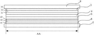
- FIG. 1 is a structural schematic diagram of a first blue OLED light-emitting layer arranged in a stacking manner with a second blue OLED light-emitting layer according to some embodiments of the present disclosure.
- the second blue OLED light-emitting layer 42 shares an anode 7 and a cathode 8 with the first blue OLED light-emitting layer 32 .
- the OLED display substrate includes the anode 7 , the second blue OLED light-emitting unit 4 , a charge generation layer 6 , a first hole injection layer 9 , the first blue OLED light-emitting unit 3 , and a cathode 8 , which are sequentially arranged in a stacking manner.
- the first blue OLED light-emitting unit 3 includes a first hole transport layer 31 , a first blue OLED light-emitting layer 32 , and a first electron transport layer 33 ;
- the second blue OLED light-emitting unit 4 includes a second hole transport layer 41 , a second blue OLED light-emitting layer 42 , and a second electron transport layer 43 .
- a structure of the OLED display substrate is simplified by sharing the anode and the cathode.
- the second blue OLED light-emitting unit 4 is shown as being connected to the anode 7 and the first blue OLED light-emitting unit 3 is shown as being connected to the cathode 8 .
- the first blue OLED light-emitting unit 3 may be connected to the anode 7
- the second blue OLED light-emitting unit 4 may be connected to the cathode 8
- the first blue OLED light-emitting unit 3 and the second blue OLED light-emitting unit 4 are connected via the charge generation layer 6 .
- positions of the first blue OLED light-emitting unit 3 and the second blue OLED light-emitting unit 4 in FIG. 1 may be mutually exchanged.
- FIG. 2 is a detailed schematic diagram of a first blue OLED light-emitting layer arranged in a stacking manner with a second blue OLED light-emitting layer according to some embodiments of the present disclosure.
- the first blue OLED light-emitting unit 3 is connected to a first anode 71 and a first cathode 81 ; the second blue OLED light-emitting unit 4 is connected to a second anode 72 and a second cathode 82 .
- the first blue OLED light-emitting unit and the second blue OLED light-emitting unit may not be connected via the charge generation layer 6 .
- the first anode 71 , the first cathode 81 , the second anode 72 , and the second cathode 82 may be made of transparent electrodes.
- positions of the first blue OLED light-emitting unit 3 and the second blue OLED light-emitting unit 4 in FIG. 2 may be mutually exchanged.
- Those skilled in the art may anticipate a structure obtained after the first blue OLED light-emitting unit 3 and the second blue OLED light-emitting unit 4 are mutually exchanged.
- the structure obtained after the first blue OLED light-emitting unit 3 and the second blue OLED light-emitting unit 4 are mutually exchanged is also within the protection scope of the present disclosure.
- the foregoing embodiment is described by using the OLED display substrate including the second blue OLED light-emitting unit and the first blue OLED light-emitting unit.
- the OLED display substrate of the present disclosure is not limited to include the second blue OLED light-emitting unit and the first blue OLED light-emitting unit, and may also include more blue OLED light-emitting units, such as a third blue OLED light-emitting unit.
- the third blue OLED light-emitting unit is arranged in a stacking manner with the first blue OLED light-emitting unit and the second blue OLED light-emitting unit, and covers the entirety of the Active Area of the OLED display substrate.
- FIG. 3 illustrates another detailed structural diagram of an OLED display substrate according to some embodiments of the present disclosure.
- the OLED display substrate includes: an anode 7 , a second blue OLED light-emitting layer 42 , a charge generation layer 6 , a first hole injection layer 9 , a first blue OLED light-emitting layer 32 and a cathode 8 that are sequentially arranged in a stacking manner.
- the OLED display substrate further includes: a second hole injection layer 44 and a second hole transport layer 41 between the anode 7 and the second blue OLED light-emitting layer 42 , wherein the second hole injection layer 44 is between the anode 7 and the second hole transport layer 41 ; a first electron injection layer 45 between the second blue OLED light-emitting layer 42 and the charge generation layer 6 ; a first electron transport layer 33 and a second electron injection layer 34 between the first blue OLED light-emitting layer 32 and the cathode 8 , wherein the second electron injection layer 34 is between the cathode 8 and the first blue OLED light-emitting layer 32 .
- FIG. 4 illustrates yet another detailed structural diagram of an OLED display substrate according to some embodiments of the present disclosure.
- the OLED display substrate includes: an anode 7 , a second blue OLED light-emitting layer 42 , a charge generation layer 6 , a first hole injection layer 9 , a first blue OLED light-emitting layer 32 and a cathode 8 that are sequentially arranged in a stacking manner.
- the OLED display substrate further includes: a second hole injection layer 44 and a second hole transport layer 41 between the anode 7 and the second blue OLED light-emitting layer 42 , wherein the second hole injection layer 44 is between the anode 7 and the second hole transport layer 41 ; a first electron injection layer 45 and a second electron transport layer 46 between the second blue OLED light-emitting layer 42 and the charge generation layer 6 , wherein the second electron transport layer 46 is between the first electron injection layer 45 and the second blue OLED light-emitting layer 42 ; a first hole transport layer 91 between the first hole injection layer 9 and the first blue OLED light-emitting layer 32 ; a first electron transport layer 33 and a second electron injection layer 34 between the first blue OLED light-emitting layer 32 and the cathode 8 , wherein the second electron injection layer 34 is between the cathode 8 and the first electron transport layer 33 .
- the quantum-dot color film layer 5 includes a red light quantum-dot layer 51 corresponding to a red sub-pixel area, and a green light quantum-dot layer 52 corresponding to a green sub-pixel area, and the quantum-dot color film layer is not provided in a blue sub-pixel area.
- the blue light emitted by the blue sub-pixel is the light directly emitted by the blue OLED light-emitting layer.
- FIG. 5 is a schematic diagram of an OLED display substrate of the present disclosure.
- the OLED display substrate of the present embodiment includes an array substrate 1 and a first blue OLED light-emitting unit 3 and a second blue OLED light-emitting unit 4 on the array substrate 1 , and further includes a quantum-dot color film layer 5 on a light-exiting side of the first blue OLED light-emitting unit 3 and the second blue OLED light-emitting unit 4 .
- the quantum-dot color film layer 5 includes a red light quantum-dot layer 51 located in the red sub-pixel area R, and a green light quantum-dot layer 52 located in the green sub-pixel area G.
- the quantum-dot color film layer is not provided in the blue sub-pixel area B, and blue light emitted by the first blue OLED light-emitting unit 3 and the second blue OLED light-emitting unit 4 is directly emitted.
- the quantum-dot color film layer 5 includes a red light quantum-dot layer R corresponding to a red sub-pixel area, a green light quantum-dot layer G corresponding to a green sub-pixel area, and a blue light quantum-dot layer B corresponding to a blue sub-pixel area.
- the blue light emitted by the blue sub-pixel is light emitted by the blue light quantum-dot layer under excitation from blue light directly emitted by the blue OLED light-emitting layer.
- FIG. 6 is a schematic diagram of an OLED display substrate of the present disclosure.
- the OLED display substrate of the present embodiment includes an array substrate 1 and a first blue OLED light-emitting unit 3 and a second blue OLED light-emitting unit 4 on the array substrate 1 , and further includes a quantum-dot color film layer 5 on a light-exiting side of the first blue OLED light-emitting unit 3 and the second blue OLED light-emitting unit 4 .
- the quantum-dot color film layer includes a red light quantum-dot layer 51 located in the red sub-pixel area R, a green light quantum-dot layer 52 located in the green sub-pixel area G, and a blue light quantum-dot layer 53 located in the blue sub-pixel area B.
- the OLED display substrate further includes a thin film encapsulation layer TE between the cathode 8 and the quantum-dot color film layer 5 .
- Some embodiments of the present disclosure also provide a display apparatus including the OLED display substrate as described above.
- the display apparatus may be any product or component having a display function, such as a television, a monitor, a digital photo frame, a mobile phone, and a tablet computer.
- the display apparatus further includes a flexible circuit board, a printed circuit board, and a back plate.
- FIG. 7 is a flowchart of a method of manufacturing an OLED display substrate provided by some embodiments of the present disclosure.
- the method of manufacturing the OLED display substrate includes the following steps S 1 -S 3 .
- Quantum dots also known as nanocrystals, are nanoparticles composed of elements in Group II-VI or elements in Group III-V. Due to a quantum confinement effect on electrons and holes, a continuous band structure becomes a discrete energy level structure with molecular characteristics, and may emit fluorescence after being excited by blue light, and an emission spectrum of the QDs may be controlled by changing a size of the quantum dots, and both fluorescence intensity and stability thereof are very good. Thus, the QD is a very good electroluminescent material.
- blue light emitted by the first blue OLED light-emitting layer excites the quantum-dot color film layer to emit red light, green light, or emit red light, green light and blue light, thereby realizing a full-color (red, blue, and green) display.
- the first blue OLED light-emitting layer and the one or more additional blue OLED light-emitting layers are formed in the entirety of the Active Area of the OLED display substrate, and the quantum dots are excited by the blue light emitted from the first blue OLED light-emitting layer and the blue light emitted from the one or more additional blue OLED light-emitting layers to emit different colors of light, which avoids manufacturing a plurality of light-emitting layers emitting different colors of light, separately, and simplifies the process of manufacturing a full-color display device.
- a wavelength of the blue light emitted by at least one additional blue OLED light-emitting layer among the one or more additional blue OLED light-emitting layers is different from a wavelength of the blue light emitted by the first blue OLED light-emitting layer, such that the first blue OLED light-emitting layer and the at least one additional blue OLED light-emitting layer may emit blue light in a plurality of different wavelength bands, which can improve a matching degree between the electroluminescent spectrum of the OLED light-emitting layer and the absorption spectrum of the quantum-dot color film layer, and improve a color conversion efficiency, a light-emitting efficiency, and a display quality of the full-color display apparatus.
- FIG. 8 is a detailed flowchart of the step S 1 of the method of manufacturing an OLED display substrate of the present disclosure.
- a wavelength of the blue light emitted by the first blue OLED light-emitting layer is in a range of 400-440 nm
- the step S 1 of forming the one or more blue OLED light-emitting layers in the Active Area on the substrate includes the following substep S 11 :
- the wavelength of the blue light emitted by the first blue OLED light-emitting layer may be 400-440 nm. Because blue light with a shorter wavelength is more harmful to human eyes, a part of the blue light in this band is generally filtered out in order to protect human eyes, which will weaken the blue light emitted by the full-color display apparatus.
- the display substrate further includes one or more additional blue OLED light-emitting layers arranged in a stacking manner with the first blue OLED light-emitting layer, and a wavelength of blue light emitted by at least one additional blue OLED light-emitting layer among the one or more additional blue OLED light-emitting layers is different from a wavelength of the blue light emitted by the first blue OLED light-emitting layer and will not be filtered out, so the light intensity of the blue light emitted by the full-color display apparatus may be guaranteed.
- the one or more additional blue OLED light-emitting layers may share the anode and the cathode with the first blue OLED light-emitting layer
- adjacent blue OLED light-emitting layers are connected via a charge generation layer.
- the charge generation layer may enable a plurality of blue OLED light-emitting layers to be connected in series. Compared with a single blue OLED light-emitting layer, the plurality of blue OLED light-emitting layers connected in series have a higher luminous efficiency.
- the wavelength 440-490 nm of the blue light emitted by the second blue OLED light-emitting layer is less harmful to the human eyes and will not be filtered out.
- the blue light emitted by the second blue OLED light-emitting layer may exit the full-color display apparatus, thereby ensuring the light intensity of the blue light emitted by the full-color display apparatus.
- the method prior to forming the second blue OLED light-emitting layer in the Active Area on the substrate, the method further includes: forming an anode on the substrate; after forming the second blue OLED light-emitting layer in the Active Area on the substrate, prior to forming the first blue OLED light-emitting layer covering the entirety of the Active Area of the OLED substrate on the second blue OLED light-emitting layer, the method further includes: sequentially forming a charge generation layer and a first hole injection layer on the second blue OLED light-emitting layer.
- the method further includes: forming a cathode on the first blue OLED light-emitting layer.
- the manufacturing method further includes: forming a second hole injection layer and a second hole transport layer between the anode and the second blue OLED light-emitting layer; forming a first electron injection layer between the second blue OLED light-emitting layer and the charge generation layer; sequentially forming a first electron transport layer and a second electron injection layer between the first blue OLED light-emitting layer and the cathode.
- the method prior to forming the second blue OLED light-emitting layer in the Active Area on the substrate, the method further includes: forming an anode on the substrate. After forming the second blue OLED light-emitting layer in the Active Area on the substrate, prior to forming the first blue OLED light-emitting layer covering the entirety of the Active Area of the OLED substrate on the second blue OLED light-emitting layer, the method further includes: sequentially forming a charge generation layer and a first hole injection layer on the second blue OLED light-emitting layer.
- the method further includes: forming a cathode on the first blue OLED light-emitting layer.
- the manufacturing method further includes: forming a second hole injection layer and a second hole transport layer between the anode and the second blue OLED light-emitting layer, wherein the second hole injection layer is between the anode and the second hole transport layer; forming a first electron injection layer and a second electron transport layer between the second blue OLED light-emitting layer and the charge generation layer, wherein the first electron injection layer is between the second electron transport layer and the charge generation layer; forming a first electron transport layer and a second electron injection layer between the first blue OLED light-emitting layer and the cathode, wherein the second electron injection layer is between the cathode and the first electron transport layer.
- forming the quantum-dot color film layer includes: forming a red light quantum-dot layer in a red sub-pixel area, forming a green light quantum-dot layer in a green sub-pixel area, and not forming the quantum-dot color film layer in a blue sub-pixel area.
- the blue light emitted by the blue sub-pixel is the light directly emitted by the blue OLED light-emitting layer.
- the method of manufacturing the OLED display substrate includes: manufacturing a blue OLED display device on an entire surface of the array substrate, wherein the blue OLED display device may specifically include an anode, a second hole injection layer, a second hole transport layer, a second blue OLED light-emitting layer, a first electron injection layer, a charge generation layer, a first hole injection layer, a first blue OLED light-emitting layer, a first electron transport layer, a second electron injection layer and a cathode; then performing a thin film encapsulation, manufacturing a quantum-dot color film layer on a light-exiting side of the thin film encapsulation layer, specifically, sequentially forming a red light quantum-dot layer in a red sub-pixel area and a green light quantum-dot layer in a green sub-pixel area.
- the quantum-dot color film layer may be manufactured by a printing process, and the quantum-dot color film layer may also be manufactured by a patterning process after a coating
- the method of manufacturing the OLED display substrate includes: manufacturing a blue OLED display device on an entire surface of an array substrate, wherein the blue OLED display device may specifically include an anode, a second hole injection layer, a second hole transport layer, a second blue OLED light-emitting layer, a second electron transport layer, a first electron injection layer, a charge generation layer, a first hole injection layer, a first hole transport layer, a first blue OLED light-emitting layer, a first electron transport layer, a second electron injection layer and a cathode; then performing a thin film encapsulation, manufacturing a quantum-dot color film layer on a light-exiting side of the thin film encapsulation layer, specifically, sequentially forming a red light quantum-dot layer in a red sub-pixel area, a green light quantum-dot layer in a green sub-pixel area, and a blue light quantum-dot layer in a blue sub-pixel area.
- forming the quantum-dot color film layer includes: forming a red light quantum-dot layer in a red sub-pixel area, forming a green light quantum-dot layer in a green sub-pixel area, and forming a blue light quantum-dot layer in a blue sub-pixel area.
- the blue light emitted by the blue sub-pixel is the light emitted by the blue light quantum-dot layer under excitation from the blue light directly emitted by the blue OLED light-emitting layer.
- the method of manufacturing the OLED display substrate includes: manufacturing a blue OLED display device on an entire surface of an array substrate, wherein the blue OLED display device may specifically include an anode, a second hole injection layer, a second hole transport layer, a second blue OLED light-emitting layer, a first electron injection layer, a charge generation layer, a first hole injection layer, a first blue OLED light-emitting layer, a first electron transport layer, a second electron injection layer and a cathode; then performing a thin film encapsulation, manufacturing a quantum-dot color film layer on a light-exiting side of the thin film encapsulation layer, specifically, sequentially forming a red light quantum-dot layer in a red sub-pixel area, a green light quantum-dot layer in a green sub-pixel area, and a blue light quantum-dot layer in a blue sub-pixel area.
- the quantum-dot color film layer may be manufactured by a printing process, and the quantum-
- the method of manufacturing the OLED display substrate includes: manufacturing a blue OLED display device on an entire surface of an array substrate, wherein the blue OLED display device may specifically include an anode, a second hole injection layer, a second hole transport layer, a second blue OLED light-emitting layer, a second electron transport layer, a first electron injection layer, a charge generation layer, a first hole injection layer, a first hole transport layer, a first blue OLED light-emitting layer, a first electron transport layer, a second electron injection layer and a cathode; then performing a thin film encapsulation, manufacturing a quantum-dot color film layer on a light-exiting side of the thin film encapsulation layer, specifically, sequentially forming a red light quantum-dot layer in a red sub-pixel area, a green light quantum-dot layer in a green sub-pixel area, and a blue light quantum-dot layer in a blue sub-pixel area.
- a first blue OLED light-emitting layer and one or more additional blue OLED light-emitting layers are formed in the entirety of the Active Area of the OLED display substrate, and the quantum dots are excited by the blue light emitted from the first blue OLED light-emitting layer and the one or more additional blue OLED light-emitting layers to emit different colors of light, which avoids manufacturing a plurality of light-emitting layers emitting different colors of light separately, and simplifies the process of manufacturing the full-color display device.
- a wavelength of blue light emitted by at least one additional blue OLED light-emitting layer among one or more blue OLED light-emitting layers is different from a wavelength of blue light emitted by the first blue OLED light-emitting layer, such that t the first blue OLED light-emitting layer and the one or more additional blue OLED light-emitting layers may emit blue light in a plurality of different wavelength bands, which can improve the matching degree between the electroluminescent spectrum of the OLED light-emitting layer and the absorption spectrum of the quantum-dot color film layer, and improve the color conversion efficiency, light-emitting efficiency, and display quality of the full-color display apparatus.
Abstract
Description
Claims (16)
Applications Claiming Priority (3)
| Application Number | Priority Date | Filing Date | Title |
|---|---|---|---|
| CN201810908575.1A CN109065740A (en) | 2018-08-10 | 2018-08-10 | Oled display substrate and preparation method thereof, display device |
| CN201810908575.1 | 2018-08-10 | ||
| PCT/CN2019/099788 WO2020030042A1 (en) | 2018-08-10 | 2019-08-08 | Oled display substrate and manufacturing method therefor, and display apparatus |
Publications (2)
| Publication Number | Publication Date |
|---|---|
| US20200273916A1 US20200273916A1 (en) | 2020-08-27 |
| US11387284B2 true US11387284B2 (en) | 2022-07-12 |
Family
ID=64683205
Family Applications (1)
| Application Number | Title | Priority Date | Filing Date |
|---|---|---|---|
| US16/639,025 Active 2039-09-01 US11387284B2 (en) | 2018-08-10 | 2019-08-08 | OLED display substrate having a quantum dot color film layer, manufacturing method of the same, and display apparatus |
Country Status (5)
| Country | Link |
|---|---|
| US (1) | US11387284B2 (en) |
| EP (1) | EP3836240A4 (en) |
| JP (1) | JP2021533520A (en) |
| CN (1) | CN109065740A (en) |
| WO (1) | WO2020030042A1 (en) |
Families Citing this family (12)
| Publication number | Priority date | Publication date | Assignee | Title |
|---|---|---|---|---|
| CN109065740A (en) * | 2018-08-10 | 2018-12-21 | 京东方科技集团股份有限公司 | Oled display substrate and preparation method thereof, display device |
| CN109509428B (en) | 2019-01-07 | 2021-01-08 | 京东方科技集团股份有限公司 | Pixel driving circuit, pixel driving method and display device |
| US20200373360A1 (en) * | 2019-05-23 | 2020-11-26 | Universal Display Corporation | Oled display panel with unpatterned emissive stack |
| WO2021062574A1 (en) * | 2019-08-07 | 2021-04-08 | Boe Technology Group Co., Ltd. | Display panel, display apparatus, light emitting element, and method of fabricating display panel |
| CN110854153A (en) * | 2019-11-08 | 2020-02-28 | 深圳雷曼光电科技股份有限公司 | Display panel and preparation method |
| CN111430444B (en) | 2020-04-30 | 2023-06-02 | 武汉华星光电半导体显示技术有限公司 | Quantum dot display panel and preparation method thereof |
| GB202010088D0 (en) * | 2020-07-01 | 2020-08-12 | Savvy Science | Novel light emitting device architectures |
| GB202010090D0 (en) | 2020-07-01 | 2020-08-12 | Savvy Science | Improved light emitting devices |
| KR20220091899A (en) * | 2020-12-24 | 2022-07-01 | 엘지디스플레이 주식회사 | Display panel and display apparatus comprising the same, and method for manufacturing the same |
| CN112928219B (en) | 2021-01-25 | 2023-07-25 | 京东方科技集团股份有限公司 | Light emitting device, display panel and light emitting method of light emitting device |
| CN113178526B (en) * | 2021-04-26 | 2022-07-26 | 京东方科技集团股份有限公司 | Electroluminescent device and display device |
| CN113314677B (en) * | 2021-05-26 | 2023-04-11 | 京东方科技集团股份有限公司 | Light-emitting device, display panel and display device |
Citations (33)
| Publication number | Priority date | Publication date | Assignee | Title |
|---|---|---|---|---|
| US20050134174A1 (en) * | 2003-12-19 | 2005-06-23 | Tohoku Pioneer Corporation | Organic EL element and method of forming the same |
| WO2006009612A1 (en) | 2004-06-16 | 2006-01-26 | Eastman Kodak Company | Array of light-emitting oled microcavity pixels |
| US7030554B2 (en) * | 2004-02-06 | 2006-04-18 | Eastman Kodak Company | Full-color organic display having improved blue emission |
| US7142179B2 (en) * | 2005-03-23 | 2006-11-28 | Eastman Kodak Company | OLED display device |
| US7279716B2 (en) * | 2004-04-14 | 2007-10-09 | Genesis Photonics Inc. | Single-chip LED with three luminescent spectrums of red, blue and green wavelengths |
| US20080297036A1 (en) * | 2007-05-31 | 2008-12-04 | Tae-Yong Noh | White organic light emitting device |
| US20090261354A1 (en) * | 2008-04-18 | 2009-10-22 | Samsung Electronics Co., Ltd. | Organic light emitting element and organic light emitting device |
| US20140204128A1 (en) * | 2013-01-18 | 2014-07-24 | Motorola Mobility Llc | Liquid crystal display with photo-luminescent material layer |
| CN104112766A (en) | 2014-07-22 | 2014-10-22 | 深圳市华星光电技术有限公司 | Color display device structure |
| CN104536198A (en) | 2015-02-03 | 2015-04-22 | 京东方科技集团股份有限公司 | Display substrate, display panel and display device |
| CN105156931A (en) | 2015-10-20 | 2015-12-16 | 京东方科技集团股份有限公司 | Backlight source, backlight module and display device |
| US20160079316A1 (en) * | 2012-09-14 | 2016-03-17 | Qd Vision, Inc. | Light emitting device including tandem structure |
| US20160190515A1 (en) * | 2014-12-30 | 2016-06-30 | Ye Xin Technology Consulting Co., Ltd. | Display panel |
| CN106094339A (en) | 2016-08-18 | 2016-11-09 | 京东方科技集团股份有限公司 | Display floater and display device |
| CN106531775A (en) | 2016-12-30 | 2017-03-22 | 京东方科技集团股份有限公司 | Organic light-emitting diode display substrate and display device and preparation method thereof |
| US20170194387A1 (en) | 2015-12-31 | 2017-07-06 | Samsung Display Co., Ltd. | Blue organic light emitting device and display device including the same |
| US20180019371A1 (en) * | 2016-03-17 | 2018-01-18 | Apple Inc. | Quantum dot spacing for high efficiency quantum dot led displays |
| US20180033994A1 (en) * | 2016-07-29 | 2018-02-01 | Lg Display Co., Ltd. | White organic light emitting device and organic light emitting display device using the same |
| US20180182990A1 (en) * | 2016-12-28 | 2018-06-28 | Lg Display Co., Ltd. | Organic light emitting diode display device |
| US20180202616A1 (en) | 2017-01-19 | 2018-07-19 | Samsung Display Co., Ltd. | Color conversion panel and display device including color conversion panel |
| CN108333833A (en) | 2018-03-08 | 2018-07-27 | 青岛海信电器股份有限公司 | Color membrane substrates and its manufacturing method, display panel, display device |
| US20180269260A1 (en) * | 2017-01-29 | 2018-09-20 | Emagin Corporation | Quantum dot array on directly patterned amoled displays and method of fabrication |
| CN109065740A (en) | 2018-08-10 | 2018-12-21 | 京东方科技集团股份有限公司 | Oled display substrate and preparation method thereof, display device |
| US20190006631A1 (en) * | 2017-06-30 | 2019-01-03 | Lg Display Co., Ltd. | Organic Light-Emitting Diode and Display Device Comprising the Same |
| US20190039349A1 (en) * | 2016-04-11 | 2019-02-07 | Toppan Printing Co., Ltd. | Barrier film laminate, method of producing the same, wavelength conversion sheet, backlight unit, and electroluminescent light-emitting unit |
| US20190064603A1 (en) * | 2017-08-25 | 2019-02-28 | Nanosys, Inc. | Using Multiple Excitation Wavelengths in Nanostructure Based Display Devices |
| US20190148648A1 (en) * | 2017-11-13 | 2019-05-16 | Samsung Display Co., Ltd. | Organic light-emitting diode and organic light-emitting display device including the same |
| US20190187338A1 (en) * | 2016-08-12 | 2019-06-20 | Toppan Printing Co., Ltd. | Phosphor protection film, wavelength conversion sheet, and light-emitting unit |
| US20200035761A1 (en) * | 2018-07-25 | 2020-01-30 | Universal Display Corporation | Energy efficient OLED TV |
| US20200174299A1 (en) * | 2017-08-04 | 2020-06-04 | Sharp Kabushiki Kaisha | Display device |
| US20200243331A1 (en) * | 2016-05-20 | 2020-07-30 | Lumileds Llc | Methods For Using Remote Plasma Chemical Vapor Deposition (RP-CVD) And Sputtering Deposition To Grow Layers In Light Emitting Devices |
| US20200251040A1 (en) * | 2017-06-23 | 2020-08-06 | Samsung Electronics Co., Ltd. | Display apparatus |
| US20210104697A1 (en) * | 2017-04-07 | 2021-04-08 | Semiconductor Energy Laboratory Co., Ltd. | Light-Emitting Element, Display Device, Electronic Device, and Lighting Device |
Family Cites Families (2)
| Publication number | Priority date | Publication date | Assignee | Title |
|---|---|---|---|---|
| US20130240847A1 (en) * | 2010-05-21 | 2013-09-19 | Solarno, Inc. | Monolithic parallel multijunction oled with independent tunable color emission |
| CN105914228B (en) * | 2016-06-02 | 2020-07-28 | 深圳市华星光电技术有限公司 | O L ED device and O L ED display |
-
2018
- 2018-08-10 CN CN201810908575.1A patent/CN109065740A/en active Pending
-
2019
- 2019-08-08 WO PCT/CN2019/099788 patent/WO2020030042A1/en unknown
- 2019-08-08 US US16/639,025 patent/US11387284B2/en active Active
- 2019-08-08 JP JP2019563744A patent/JP2021533520A/en active Pending
- 2019-08-08 EP EP19845901.8A patent/EP3836240A4/en not_active Withdrawn
Patent Citations (38)
| Publication number | Priority date | Publication date | Assignee | Title |
|---|---|---|---|---|
| US20050134174A1 (en) * | 2003-12-19 | 2005-06-23 | Tohoku Pioneer Corporation | Organic EL element and method of forming the same |
| US7030554B2 (en) * | 2004-02-06 | 2006-04-18 | Eastman Kodak Company | Full-color organic display having improved blue emission |
| US7279716B2 (en) * | 2004-04-14 | 2007-10-09 | Genesis Photonics Inc. | Single-chip LED with three luminescent spectrums of red, blue and green wavelengths |
| WO2006009612A1 (en) | 2004-06-16 | 2006-01-26 | Eastman Kodak Company | Array of light-emitting oled microcavity pixels |
| US7142179B2 (en) * | 2005-03-23 | 2006-11-28 | Eastman Kodak Company | OLED display device |
| US20080297036A1 (en) * | 2007-05-31 | 2008-12-04 | Tae-Yong Noh | White organic light emitting device |
| US20090261354A1 (en) * | 2008-04-18 | 2009-10-22 | Samsung Electronics Co., Ltd. | Organic light emitting element and organic light emitting device |
| US20160079316A1 (en) * | 2012-09-14 | 2016-03-17 | Qd Vision, Inc. | Light emitting device including tandem structure |
| US20140204128A1 (en) * | 2013-01-18 | 2014-07-24 | Motorola Mobility Llc | Liquid crystal display with photo-luminescent material layer |
| CN104112766A (en) | 2014-07-22 | 2014-10-22 | 深圳市华星光电技术有限公司 | Color display device structure |
| US20160027848A1 (en) | 2014-07-22 | 2016-01-28 | Shenzhen China Star Optoelectronics Technology Co. Ltd. | Color Display Device Structure |
| US20160190515A1 (en) * | 2014-12-30 | 2016-06-30 | Ye Xin Technology Consulting Co., Ltd. | Display panel |
| CN104536198A (en) | 2015-02-03 | 2015-04-22 | 京东方科技集团股份有限公司 | Display substrate, display panel and display device |
| US20160370655A1 (en) | 2015-02-03 | 2016-12-22 | Boe Technology Group Co., Ltd. | Display substrate, display panel and display device |
| CN105156931A (en) | 2015-10-20 | 2015-12-16 | 京东方科技集团股份有限公司 | Backlight source, backlight module and display device |
| CN106935714A (en) | 2015-12-31 | 2017-07-07 | 三星显示有限公司 | Organic light emitting device in blue color and the display device including organic light emitting device in blue color |
| US20170194387A1 (en) | 2015-12-31 | 2017-07-06 | Samsung Display Co., Ltd. | Blue organic light emitting device and display device including the same |
| US20180019371A1 (en) * | 2016-03-17 | 2018-01-18 | Apple Inc. | Quantum dot spacing for high efficiency quantum dot led displays |
| US20190039349A1 (en) * | 2016-04-11 | 2019-02-07 | Toppan Printing Co., Ltd. | Barrier film laminate, method of producing the same, wavelength conversion sheet, backlight unit, and electroluminescent light-emitting unit |
| US20200243331A1 (en) * | 2016-05-20 | 2020-07-30 | Lumileds Llc | Methods For Using Remote Plasma Chemical Vapor Deposition (RP-CVD) And Sputtering Deposition To Grow Layers In Light Emitting Devices |
| US20180033994A1 (en) * | 2016-07-29 | 2018-02-01 | Lg Display Co., Ltd. | White organic light emitting device and organic light emitting display device using the same |
| US20190187338A1 (en) * | 2016-08-12 | 2019-06-20 | Toppan Printing Co., Ltd. | Phosphor protection film, wavelength conversion sheet, and light-emitting unit |
| CN106094339A (en) | 2016-08-18 | 2016-11-09 | 京东方科技集团股份有限公司 | Display floater and display device |
| US20180182990A1 (en) * | 2016-12-28 | 2018-06-28 | Lg Display Co., Ltd. | Organic light emitting diode display device |
| US20180190921A1 (en) | 2016-12-30 | 2018-07-05 | Boe Technology Group Co., Ltd. | Organic light-emitting diode display substrate, and display apparatus and production method thereof |
| CN106531775A (en) | 2016-12-30 | 2017-03-22 | 京东方科技集团股份有限公司 | Organic light-emitting diode display substrate and display device and preparation method thereof |
| US20180202616A1 (en) | 2017-01-19 | 2018-07-19 | Samsung Display Co., Ltd. | Color conversion panel and display device including color conversion panel |
| CN108333826A (en) | 2017-01-19 | 2018-07-27 | 三星显示有限公司 | Color conversion panel and display equipment including color conversion panel |
| US20180269260A1 (en) * | 2017-01-29 | 2018-09-20 | Emagin Corporation | Quantum dot array on directly patterned amoled displays and method of fabrication |
| US20210104697A1 (en) * | 2017-04-07 | 2021-04-08 | Semiconductor Energy Laboratory Co., Ltd. | Light-Emitting Element, Display Device, Electronic Device, and Lighting Device |
| US20200251040A1 (en) * | 2017-06-23 | 2020-08-06 | Samsung Electronics Co., Ltd. | Display apparatus |
| US20190006631A1 (en) * | 2017-06-30 | 2019-01-03 | Lg Display Co., Ltd. | Organic Light-Emitting Diode and Display Device Comprising the Same |
| US20200174299A1 (en) * | 2017-08-04 | 2020-06-04 | Sharp Kabushiki Kaisha | Display device |
| US20190064603A1 (en) * | 2017-08-25 | 2019-02-28 | Nanosys, Inc. | Using Multiple Excitation Wavelengths in Nanostructure Based Display Devices |
| US20190148648A1 (en) * | 2017-11-13 | 2019-05-16 | Samsung Display Co., Ltd. | Organic light-emitting diode and organic light-emitting display device including the same |
| CN108333833A (en) | 2018-03-08 | 2018-07-27 | 青岛海信电器股份有限公司 | Color membrane substrates and its manufacturing method, display panel, display device |
| US20200035761A1 (en) * | 2018-07-25 | 2020-01-30 | Universal Display Corporation | Energy efficient OLED TV |
| CN109065740A (en) | 2018-08-10 | 2018-12-21 | 京东方科技集团股份有限公司 | Oled display substrate and preparation method thereof, display device |
Non-Patent Citations (2)
| Title |
|---|
| International Search Report of PCT/CN2019/099788 and English translation, dated Oct. 30, 2019, 14 pages. |
| Office Action of CN Application No. 201810908575.1 and English translation, dated Sep. 9, 2019, 22 pages. |
Also Published As
| Publication number | Publication date |
|---|---|
| US20200273916A1 (en) | 2020-08-27 |
| EP3836240A1 (en) | 2021-06-16 |
| WO2020030042A1 (en) | 2020-02-13 |
| EP3836240A4 (en) | 2022-05-04 |
| CN109065740A (en) | 2018-12-21 |
| JP2021533520A (en) | 2021-12-02 |
Similar Documents
| Publication | Publication Date | Title |
|---|---|---|
| US11387284B2 (en) | OLED display substrate having a quantum dot color film layer, manufacturing method of the same, and display apparatus | |
| US10461131B2 (en) | Quantum dot LED and OLED integration for high efficiency displays | |
| US9379344B2 (en) | Display panel and display device | |
| US10205129B2 (en) | Organic light emitting display panel comprising a quantum material layer, manufacturing method thereof, and display device | |
| US10573850B2 (en) | Manufacturing OLED panel by utilizing morphological transformation layer | |
| US11211574B2 (en) | Light emitting device and fabrication method thereof, and electronic apparatus | |
| EP2485568B1 (en) | Organic electroluminescent element | |
| US20150263075A1 (en) | Method of manufacturing organic light emitting display device | |
| US20170133614A1 (en) | Light-Emiting Device and Manufacturing Method Therefor, Display Apparatus, and Optical Detection Apparatus | |
| US10121983B2 (en) | Light-emitting device including nano particle having core shell structure | |
| KR20150037235A (en) | Organic light emitting diode display | |
| CN110611035A (en) | Quantum dot OLED display panel | |
| US10854686B2 (en) | Package structure consisting of quantum dot material and packaging method for organic electroluminescence element and display device | |
| CN110048024B (en) | Display substrate, manufacturing method thereof and display device | |
| CN209880662U (en) | Quantum dot light-emitting device and display device | |
| US11737343B2 (en) | Method of manufacturing perovskite light emitting device by inkjet printing | |
| US20220052262A1 (en) | Method of manufacturing perovskite light emitting device by inkjet printing | |
| KR20220103844A (en) | Display device and method of manufacturing the same | |
| CN107507917B (en) | OLED device, preparation method thereof and display device | |
| CN114695689A (en) | Display device with a light-shielding layer | |
| CN113707702B (en) | Display substrate, preparation method thereof and display device | |
| US20220020950A1 (en) | Light-emitting device and electronic apparatus including same | |
| US20240071306A1 (en) | Display device and driving method thereof | |
| CN114695751A (en) | Display device and preparation method thereof | |
| CN115768173A (en) | Display panel, preparation method thereof and display device |
Legal Events
| Date | Code | Title | Description |
|---|---|---|---|
| FEPP | Fee payment procedure |
Free format text: ENTITY STATUS SET TO UNDISCOUNTED (ORIGINAL EVENT CODE: BIG.); ENTITY STATUS OF PATENT OWNER: LARGE ENTITY |
|
| AS | Assignment |
Owner name: BOE TECHNOLOGY GROUP CO., LTD., CHINA Free format text: ASSIGNMENT OF ASSIGNORS INTEREST;ASSIGNORS:JIAO, ZHIQIANG;YUAN, GUANGCAI;REEL/FRAME:051824/0015 Effective date: 20191223 |
|
| STPP | Information on status: patent application and granting procedure in general |
Free format text: APPLICATION DISPATCHED FROM PREEXAM, NOT YET DOCKETED |
|
| STPP | Information on status: patent application and granting procedure in general |
Free format text: DOCKETED NEW CASE - READY FOR EXAMINATION |
|
| STPP | Information on status: patent application and granting procedure in general |
Free format text: NON FINAL ACTION MAILED |
|
| STPP | Information on status: patent application and granting procedure in general |
Free format text: RESPONSE TO NON-FINAL OFFICE ACTION ENTERED AND FORWARDED TO EXAMINER |
|
| STPP | Information on status: patent application and granting procedure in general |
Free format text: EX PARTE QUAYLE ACTION MAILED |
|
| STPP | Information on status: patent application and granting procedure in general |
Free format text: RESPONSE TO EX PARTE QUAYLE ACTION ENTERED AND FORWARDED TO EXAMINER |
|
| STPP | Information on status: patent application and granting procedure in general |
Free format text: NOTICE OF ALLOWANCE MAILED -- APPLICATION RECEIVED IN OFFICE OF PUBLICATIONS |
|
| STCF | Information on status: patent grant |
Free format text: PATENTED CASE |