US11382248B2 - Dispensing head - Google Patents

Dispensing head Download PDF

Info

Publication number
US11382248B2
US11382248B2 US16/992,835 US202016992835A US11382248B2 US 11382248 B2 US11382248 B2 US 11382248B2 US 202016992835 A US202016992835 A US 202016992835A US 11382248 B2 US11382248 B2 US 11382248B2
Authority
US
United States
Prior art keywords
spindle
axis
pick
motor
place
Prior art date
Legal status (The legal status is an assumption and is not a legal conclusion. Google has not performed a legal analysis and makes no representation as to the accuracy of the status listed.)
Active
Application number
US16/992,835
Other versions
US20200375074A1 (en
Inventor
John Danek
Peter Joseph Dionne
Current Assignee (The listed assignees may be inaccurate. Google has not performed a legal analysis and makes no representation or warranty as to the accuracy of the list.)
Universal Instruments Corp
Original Assignee
Universal Instruments Corp
Priority date (The priority date is an assumption and is not a legal conclusion. Google has not performed a legal analysis and makes no representation as to the accuracy of the date listed.)
Filing date
Publication date
Priority claimed from US16/969,751 external-priority patent/US11464146B2/en
Application filed by Universal Instruments Corp filed Critical Universal Instruments Corp
Priority to US16/992,835 priority Critical patent/US11382248B2/en
Assigned to UNIVERSAL INSTRUMENTS CORPORATION reassignment UNIVERSAL INSTRUMENTS CORPORATION ASSIGNMENT OF ASSIGNORS INTEREST (SEE DOCUMENT FOR DETAILS). Assignors: DANEK, John, DIONNE, Peter Joseph
Publication of US20200375074A1 publication Critical patent/US20200375074A1/en
Application granted granted Critical
Publication of US11382248B2 publication Critical patent/US11382248B2/en
Active legal-status Critical Current
Anticipated expiration legal-status Critical

Links

Images

Classifications

    • HELECTRICITY
    • H05ELECTRIC TECHNIQUES NOT OTHERWISE PROVIDED FOR
    • H05KPRINTED CIRCUITS; CASINGS OR CONSTRUCTIONAL DETAILS OF ELECTRIC APPARATUS; MANUFACTURE OF ASSEMBLAGES OF ELECTRICAL COMPONENTS
    • H05K13/00Apparatus or processes specially adapted for manufacturing or adjusting assemblages of electric components
    • H05K13/04Mounting of components, e.g. of leadless components
    • H05K13/0404Pick-and-place heads or apparatus, e.g. with jaws
    • H05K13/0413Pick-and-place heads or apparatus, e.g. with jaws with orientation of the component while holding it; Drive mechanisms for gripping tools, e.g. lifting, lowering or turning of gripping tools
    • BPERFORMING OPERATIONS; TRANSPORTING
    • B65CONVEYING; PACKING; STORING; HANDLING THIN OR FILAMENTARY MATERIAL
    • B65GTRANSPORT OR STORAGE DEVICES, e.g. CONVEYORS FOR LOADING OR TIPPING, SHOP CONVEYOR SYSTEMS OR PNEUMATIC TUBE CONVEYORS
    • B65G47/00Article or material-handling devices associated with conveyors; Methods employing such devices
    • B65G47/74Feeding, transfer, or discharging devices of particular kinds or types
    • B65G47/90Devices for picking-up and depositing articles or materials
    • B65G47/91Devices for picking-up and depositing articles or materials incorporating pneumatic, e.g. suction, grippers
    • HELECTRICITY
    • H05ELECTRIC TECHNIQUES NOT OTHERWISE PROVIDED FOR
    • H05KPRINTED CIRCUITS; CASINGS OR CONSTRUCTIONAL DETAILS OF ELECTRIC APPARATUS; MANUFACTURE OF ASSEMBLAGES OF ELECTRICAL COMPONENTS
    • H05K13/00Apparatus or processes specially adapted for manufacturing or adjusting assemblages of electric components
    • H05K13/04Mounting of components, e.g. of leadless components
    • H05K13/0404Pick-and-place heads or apparatus, e.g. with jaws
    • H05K13/0408Incorporating a pick-up tool
    • H05K13/0409Sucking devices
    • HELECTRICITY
    • H05ELECTRIC TECHNIQUES NOT OTHERWISE PROVIDED FOR
    • H05KPRINTED CIRCUITS; CASINGS OR CONSTRUCTIONAL DETAILS OF ELECTRIC APPARATUS; MANUFACTURE OF ASSEMBLAGES OF ELECTRICAL COMPONENTS
    • H05K13/00Apparatus or processes specially adapted for manufacturing or adjusting assemblages of electric components
    • H05K13/04Mounting of components, e.g. of leadless components
    • H05K13/0404Pick-and-place heads or apparatus, e.g. with jaws
    • H05K13/0408Incorporating a pick-up tool
    • H05K13/041Incorporating a pick-up tool having multiple pick-up tools
    • HELECTRICITY
    • H05ELECTRIC TECHNIQUES NOT OTHERWISE PROVIDED FOR
    • H05KPRINTED CIRCUITS; CASINGS OR CONSTRUCTIONAL DETAILS OF ELECTRIC APPARATUS; MANUFACTURE OF ASSEMBLAGES OF ELECTRICAL COMPONENTS
    • H05K13/00Apparatus or processes specially adapted for manufacturing or adjusting assemblages of electric components
    • H05K13/04Mounting of components, e.g. of leadless components
    • H05K13/0404Pick-and-place heads or apparatus, e.g. with jaws
    • H05K13/0406Drive mechanisms for pick-and-place heads, e.g. details relating to power transmission, motors or vibration damping

Definitions

  • Assembly machines include complex robots that have dispensing heads that move along one or more axis to assemble an unfinished product.
  • Dispensing heads may be capable of picking, placing, providing material to a component or surface, manipulating, screwing, or otherwise dispensing of a task or material.
  • pick-and-place assembly machines for example, dispensing heads are often configured to receive multiple different spindle and nozzle assemblies in order to pick, place, and assemble various different parts efficiently.
  • Dispensing heads must often include a spindle assembly for creating rotation in a nozzle, along with the ability to move the nozzle in the Z-axis. As a result of these requirements, dispensing heads for pick-and-place machines are often heavy and have a large volume.
  • assembly machines may include multi-spindle or multi-nozzle dispensing heads. These dispensing heads may be configured to, for example, pick up multiple components from one or more feeder banks, and then move to a placement location to place the multiple components. This reduces assembly time compared to having a single spindle or single nozzle. This is because single spindle and nozzle arrangements will typically require the back and forth movement between the feeder banks and the placement location with each placed component. However, with additional spindles and nozzle receivers located on a dispensing head, the size, volume and engineering complexity of the head is often increased. Further, if one spindle or nozzle breaks or begins functioning improperly, the entire dispensing head may be compromised until such a problem is fixed.
  • present dispensing heads for pick-and-place systems are typically controlled by machine level processors or control systems. These systems preclude the creation of an independent motion control profile for each individual spindle on a multi-spindle dispensing head. Rather, motion control profiles are created on a dispensing head level.
  • a spindle for a pick-and-place machine comprises: a shaft including a length extending between a first end and a second end, the shaft including an outer body and a hollow interior; a nozzle tip disposed at the first end of the shaft, the nozzle tip configured to contact an electronic component for manipulation of the electronic component; and a theta gear disposed on the shaft, the theta gear configured to engage with a motor of a pick-and-place head, wherein the spindle is configured to be removably attachable from the pick-and-place head.
  • a method of assembly comprises: providing a pick-and-place machine having a pick-and-place head; providing a spindle for the pick-and-place machine, the spindle including: a shaft including a length extending between a first end and a second end, the shaft including an outer body and a hollow interior; a nozzle tip disposed at the first end of the shaft; a theta gear disposed on the shaft; attaching the spindle to the pick-and-place head of the pick-and-place machine; engaging, by the theta gear, with a motor of the pick-and-place head; contacting, by the spindle, an electrical component; manipulating, by the spindle, the electrical component; and removing the spindle from the pick-and-place head of the pick-and-place machine.
  • a dispensing head comprises: a body structure including a receiving location; a z-axis motor; a theta motor; a spindle received in the receiving location, the spindle comprising: a shaft including a length extending between a first end and a second end, the shaft including an outer body and a hollow interior; a nozzle tip disposed at the first end of the shaft, the nozzle tip configured to contact an electronic component for manipulation of the electronic component; and a theta gear disposed on the shaft, the theta gear configured to engage with the theta motor such that the theta motor is configured to rotate the theta gear.
  • a spindle bank for a pick-and-place machine comprises: a base including a plurality of mount locations, each of the plurality of mount locations configured to receive a mountable spindle module including at least one pick-and-place spindle and nozzle; and a bearing system attachable to a movement axis of a pick-and-place machine such that the spindle bank is movable along the movement axis.
  • a pick-and-place machine comprises: a feeder location configured to present electronic components for picking; a placement location configured to receive an unfinished product to place the electronic components; a first movement axis; and a spindle bank including: a base including a plurality of mount locations, each of the plurality of mount locations configured to receive a mountable spindle module including at least one pick-and-place spindle and nozzle; and a bearing system attachable to the first movement axis such that the spindle bank is movable along the first movement axis.
  • a method of assembly comprising: providing a pick-and-place machine having a first movement axis; providing a spindle bank for a pick-and-place machine including: a base including a plurality of mount locations; and a bearing system attachable to the first movement axis of a pick-and-place machine such that the spindle bank is movable along the axis; and mounting, on each of the plurality of mount locations, a mountable spindle module including at least one pick-and-place spindle and nozzle; and assembling, by the received mountable spindle modules, at least one unfinished product.
  • a pick-and-place spindle module comprises: a modular body structure including a first receiving location configured to receive a spindle; a first z-axis motor configured to move a spindle received in the first receiving location in a z-axis; a first theta motor configured to rotate a spindle received in the receiving location; an air distribution system including an air distribution port, the air distribution system configured to deliver received air from the air distribution port to a spindle received in the first receiving location; an electrical distribution system including an electrical distribution port, the electrical distribution system configured to deliver received electricity from the electricity distribution port to the first z-axis motor and the first theta motor; and a mechanical attachment mechanism, the mechanical attachment mechanism configured to facilitate attachment of the modular body structure to a spindle bank such that the air distribution port is connected to receive air from the spindle bank and the electrical distribution port is configured to receive electricity from the spindle bank.
  • a method of assembly comprises: providing a pick-and-place machine having a first movement axis; providing a spindle bank attached to the pick and place machine such that the spindle bank is movable along the first movement axis: providing a first pick-and-place spindle module including: a modular body structure including a first receiving location; a first z-axis motor; a first theta motor; an air distribution system including an air distribution port; an electrical distribution system including an electrical distribution port; and a mechanical attachment mechanism; attaching, using the mechanical attachment mechanism, the first pick-and-place spindle module to the spindle bank such that the air distribution port is connected to receive air from an element of the spindle bank and the electrical distribution port is connected to receive electricity from an element of the spindle bank; receiving, by the receiving location of the modular body structure, a first spindle; moving, by the first z-axis motor, the received first spindle in a z-axis; rotating, by the first theta
  • a pick-and-place machine comprises: a feeder location configured to present electronic components for picking; a placement location configured to receive an unfinished product to place the electronic components; a first movement axis; a spindle bank movable along the first movement axis; and a pick-and-place spindle module attached to the spindle bank including: a modular body structure including a first receiving location configured to receive a spindle; a first z-axis motor configured to move a spindle received in the first receiving location in a z-axis; a first theta motor configured to rotate a spindle received in the receiving location; an air distribution system including an air distribution port, the air distribution system configured to deliver received air from the air distribution port to a spindle received in the first receiving location; an electrical distribution system including an electrical distribution port, the electrical distribution system configured to deliver received electricity from the electricity distribution port to the first z-axis motor and the first theta motor; and a mechanical attachment mechanism, the mechanical attachment mechanism attaching the
  • a pick-and-place spindle module comprises: a modular body structure including a first receiving location configured to receive a spindle; a first z-axis motor configured to move a spindle received in the first receiving location in a z-axis; a first theta motor configured to rotate a spindle received in the receiving location; a first motion control chip each attached to the body structure, the first motion control chip configured to control the first z-axis motor and the first theta motor; and a mechanical attachment mechanism, the mechanical attachment mechanism configured to facilitate attachment of the modular body structure to a spindle bank.
  • a pick-and-place spindle bank comprises: a base including a plurality of mount locations; a bearing system attachable to an axis of a pick-and-place machine such that the spindle bank is movable along the axis; and a first pick-and-place spindle module mounted to a first of the plurality of mount locations, the first pick-and-place spindle module including: a modular body structure including a first receiving location configured to receive a spindle; a first z-axis motor configured to move a spindle received in the first receiving location in a z-axis; a first theta motor configured to rotate a spindle received in the first receiving location; a first motion control chip each attached to the modular body structure, the first motion control chip configured to control the first z-axis motor and the first theta motor; and a mechanical attachment mechanism attaching the modular body structure to the base.
  • a pick-and-place head comprises: a body structure; a plurality of z-axis motors attached to the body structure, each configured to move a spindle in a z-axis; a plurality of theta motors attached to the body structure each configured to rotate a spindle; and a plurality of motion control chips each attached to the body structure, each of the plurality of motion control chips configured to control a single one of the plurality of z-axis motors and a single one of the plurality of theta motors.
  • a method of assembly comprises: providing a pick-and-place head that includes: a body structure; a plurality of z-axis motors attached to the body structure, each configured to move a spindle in a z-axis; a plurality of theta motors attached to the body structure each configured to rotate a spindle; and a plurality of motion control chips each attached to the body structure, controlling, with each of the plurality of motion control chips, a single one of the plurality of z-axis motors and a single one of the plurality of theta motors; and at least partially assembling, with the pick and place head, an unfinished product.
  • a pick-and-place dispensing head comprises: a body structure including a first z-axis motor attachment location, a second z-axis motor attachment location, a first linear track and a second linear track; a first z-axis motor attached to the body structure at the first z-axis motor attachment location; a second z-axis motor attached to the body structure at the second z-axis motor attachment location; a first body attached to the first linear track and operably connected to the first z-axis motor such that the first body moves along the first linear track when the first z-axis motor is actuated; a second body attached to the second linear track and operably connected to the second z-axis motor such that the second body moves along the second linear track when the second z-axis motor is actuated; a first theta motor operably connected to the first body; a second theta motor operably connected to the second body; a first receiving location operably connected to the first body, the first receiving location configured
  • a pick-and-place dispensing head comprises: a body structure extending in an x-axis, a y-axis perpendicular to the x-axis, and a z-axis perpendicular to the x-axis and the y-axis, the body structure including a first z-axis motor attachment location, a second z-axis motor attachment location, a first linear track extending along the z-axis and a second linear track extending along the z-axis; a first z-axis motor attached to the body structure at the first z-axis motor attachment location, the first z-axis motor configured to exact movement in the z-axis; a second z-axis motor attached to the body structure at the second z-axis motor attachment location, the second z-axis motor configured to exact movement in the z-axis; a first body attached to the first linear track and operably connected to the first z-axis motor such that the first
  • a pick-and-place dispensing head comprises: a body structure having a z-axis motor attachment location and a linear track; a z-axis motor attached to the body structure at the axis motor attachment location, the z-axis motor configured to exact movement in a z-axis; a body attached to the linear track and operably connected to the z-axis motor such that the body moves along the linear track when the z-axis motor is actuated; a theta motor operably connected to the first body; a receiving location operably connected to the body, the receiving location configured to receive a pick-and-place spindle such that the pick-and-place spindle is configured to move relative the body in the z-axis when an upward z-axis force is applied to the pick-and-place spindle, the receiving location including a spring mechanism configured to return the spindle to a start position after actuation by the z-axis motor, and wherein the first theta motor is configured
  • FIG. 1 depicts a perspective view of an assembly machine in accordance with one embodiment
  • FIG. 2A depicts a perspective view of the assembly machine of FIG. 1 with covers removed in accordance with one embodiment
  • FIG. 2B depicts a perspective view of a portion of the assembly machine of FIG. 2A enlarged at circle A in accordance with one embodiment
  • FIG. 3 depicts a perspective view of a spindle module in accordance with one embodiment
  • FIG. 4 depicts a perspective view of a body structure of the spindle module in accordance with one embodiment
  • FIG. 5 depicts a front view of the body structure of FIG. 4 in accordance with one embodiment
  • FIG. 6 depicts a partially exploded view of the spindle module of FIG. 3 in accordance with one embodiment
  • FIG. 7A depicts a side view of the spindle module of FIG. 3 in accordance with one embodiment
  • FIG. 7B depicts a cross sectional view of the spindle module of FIG. 7A taken at arrows A-A in accordance with one embodiment
  • FIG. 8 is a perspective view of a spindle nozzle in accordance with one embodiment
  • FIG. 9 is a side view of the spindle nozzle of FIG. 12 in accordance with one embodiment
  • FIG. 10 depicts a side cutaway view of the spindle module of FIG. 3 in accordance with one embodiment
  • FIG. 11 depicts a front view of the spindle module of FIG. 3 with the first z-axis motor actuated in accordance with one embodiment
  • FIG. 12A depicts a perspective view of the spindle module of FIG. 3 with the first z-axis motor actuated in accordance with one embodiment
  • FIG. 12B depicts a perspective view of a portion of the spindle module of FIG. 12A enlarged at circle B in accordance with one embodiment
  • FIG. 13A depicts a perspective view of the spindle module of FIG. 3 with the first z-axis motor actuated in accordance with one embodiment
  • FIG. 13B depicts a perspective view of a portion of the spindle module of FIG. 13A enlarged at circle C in accordance with one embodiment
  • FIG. 14 is a perspective view of a spindle bank in accordance with one embodiment.
  • FIG. 15 is a perspective view of the spindle bank of FIG. 14 with a plurality of spindle modules attached in accordance with one embodiment.
  • the assembly machine 10 is a pick-and-place machine configured to assemble printed circuit boards (PCB's) in the embodiment shown.
  • the assembly machine may be an advanced packaging assembly machine, a component assembly machine, or the like.
  • the features described herein may be applied to various other assembly machines such as odd form assembly machines (OFA), or the like.
  • the Assembly machine 10 includes a frame 12 providing structure a body 14 having covers 16 a , 16 b .
  • the frame 12 may include a plurality of legs upon which the assembly machine 10 is configured to stand.
  • the assembly machine 10 includes a plurality of feeder banks 18 a , 18 b .
  • a plurality of feeders 20 are disposed (shown in FIG.
  • the feeders 20 may each include a plurality of electronic components that the assembly machine 10 is configured to pick-and-place onto a PCB to assemble or at least partially assemble the PCB.
  • the assembly machine 10 further includes a board handling opening 22 .
  • a board handling track 24 may extend within the body 14 of the assembly machine 10 extending between the opening 22 and another opening on the opposing side of the assembly machine (not shown).
  • the board handling track 24 may be configured to receive a PCB or another unfinished product and transport the PCB to a placement location within the body of the assembly machine 10 for assembly.
  • the assembly machine 10 is shown further including operator interface and control displays 26 a , 26 b , one on each side.
  • the display 26 may be configured to receive user or operator inputs and display information necessary or useful to a user or operator. While the features of the assembly machine 10 shown are one exemplary embodiment, aspects of the invention described herein are applicable to various other types of assembly machines as will be apparent to those skilled in the art.
  • the assembly machine 10 is shown with the covers 16 a , 16 b removed exposing an interior 28 of the assembly machine 10 .
  • the assembly machine 10 includes two additional feeder banks 18 c , 18 d disposed on the opposite side of the body 14 as the feeder banks 18 a , 18 b .
  • the board handling track 24 may be located between the feeder banks 18 a , 18 b and 18 c , 18 d .
  • the board handling track 24 may be configured to provide an unfinished product such as a PCB to a placement station 30 located along the track 24 .
  • the assembly machine 10 may facilitate movement of components in three movement axes: an x-axis, a y-axis and a z-axis.
  • the x-axis may be an axis extending parallel to the board handling track 24 .
  • the y-axis may be perpendicular to the x-axis and the board handling track 24 .
  • the z-axis may be an up and down or vertical axis.
  • the assembly machine 10 may include a plurality of movement axes 32 , 34 , 36 , 38 for facilitating movement in the x-axis and the y-axis.
  • the assembly machine 10 may include a first movement axis 32 and a second movement axis 34 that are configured to facilitate movement in the y-axis.
  • the assembly machine 10 may include a third movement axis 36 and a second movement axis 38 that are configured to facilitate movement in the x-axis.
  • the first and the second movement axis 32 may extend along a depth of the machine between a first side 40 and a second side 42 .
  • the first side 40 is the side of the assembly machine 10 proximate the first and second feeder banks 18 a , 18 b .
  • the second side 42 is the side of the assembly machine 10 proximate the third and fourth feeder banks 18 c , 18 d .
  • the third and fourth movement axes 36 , 38 are shown connected to the first and second movement axes 32 , 34 and extend there between. During operation of the assembly machine 10 , the third and fourth movement axes 36 , 38 are configured to each independently move along the first and second movement axes 32 , 34 to provide for movement in the y-axis.
  • a spindle bank 100 a , 100 b is shown movably attached to each of the third and fourth movement axes 36 , 38 , respectively.
  • the spindle banks 100 a , 100 b may each be configured to move along the x-axis by moving along the respective third and fourth movement axes 36 , 38 .
  • the assembly machine 10 may be a single-moveable axis machine. For example, there may be a single x-axis and a single y-axis connectable to the assembly machine, rather than two of each as shown in the embodiment in the Figures.
  • the spindle banks 100 a , 100 b within the assembly machine 10 are configured for both x-axis and y-axis freedom of operation within the interior 28 .
  • This allows the spindle banks 100 a , 100 b to move back and forth to and from the feeder banks 18 a , 18 b , 18 c , 18 d and the placement station 30 .
  • This is accomplished by both the movement of the spindle banks 100 a , 100 b along the respective third and fourth movement axes 36 , 38 , and the movement of the third and fourth movement axes 36 , 38 along the first and second movement axes 32 , 34 .
  • Other forms of x-axis and y-axis movement within the assembly machine 10 are contemplated and the movement axes shown are for exemplary purposes.
  • FIG. 2B a perspective view of a portion of the assembly machine 10 enlarged at circle A (from FIG. 2A ) is shown.
  • the enlarged portion shows the spindle bank 100 a having a base 110 and a bearing system 112 .
  • the base 110 may be a body, housing, structure or the like.
  • the base 110 may include a plurality of mount locations 114 a , 114 b , 114 c , 114 d , 114 e , 114 f , 114 g , 114 h each configured to receive a spindle module 200 a , 200 b , 200 c , 200 d , 200 e , 200 f , 200 g , 200 h , respectively.
  • the spindle modules described herein may be pick-and-place spindle modules particularly configured for receiving spindle and nozzle combinations that are configured to pick, place, or otherwise manipulate electronic components for printed circuit board assembly and picking and placement processes.
  • the spindle modules described herein may also be utilized for other assembly processes where one or more rotatable and/or descendible manipulating spindles are necessary to perform at least a portion of an assembly process for assembling an unfinished product.
  • the bearing system 112 may be a system that provides for movement of the spindle bank 100 a along the third movement axis 36 .
  • the bearing system 112 may include wheels to facilitate movement between the spindle bank 100 a and the movement axis 36 .
  • the bearing system 112 may include magnets to facilitate magnetic movement between the spindle bank 100 a and the third movement axis 36 .
  • the third movement axis 36 may include a track structure on the underside (not shown) that may cooperate with a track structure bearing system of the spindle bank 100 a .
  • the spindle bank 100 may include track runner bearings configured to cooperate with a track of the third movement axis 36 .
  • a motor or other movement creating mechanism may provide for controlled powered movement of the spindle bank 100 along the third movement axis 36 .
  • the motor may be located on the spindle bank itself 100 , or may be located on the third movement axis 36 .
  • the spindle bank 100 may include one or more electrical ports, connectors or the like to connect to an electrical system of the assembly machine 10 to thereby provide electrical power to the spindle bank 100 .
  • the spindle bank 100 may utilize this electricity to power a motor or otherwise provide motion, movement, or acceleration of the spindle bank 100 relative to the third movement axis 36 .
  • the mount locations 114 a , 114 b , 114 c , 114 d , 114 e , 114 f , 114 g , 114 h may provide for modularity in the spindle bank 100 a such that the spindle bank 100 a may be operable with each of the spindle modules 200 a , 200 b , 200 c , 200 d , 200 e , 200 f , 200 g , 200 h attached or with a single one of the spindle modules.
  • the spindle bank 100 a may be operable no matter how many of the spindle modules 200 a , 200 b , 200 c , 200 d , 200 e , 200 f , 200 g , 200 h are installed into the mount locations 114 a , 114 b , 114 c , 114 d , 114 e , 114 f , 114 g , 114 h . If one of the spindle modules 200 a , 200 b , 200 c , 200 d , 200 e , 200 f , 200 g , 200 h breaks or is need of repair, the spindle bank 100 a may be operable.
  • the mount locations 114 a , 114 b , 114 c , 114 d , 114 e , 114 f , 114 g , 114 h may each be configured to receive different types of spindle modules with different types of spindles, nozzles and the like.
  • the mount locations 114 a , 114 b , 114 c , 114 d , 114 e , 114 f , 114 g , 114 h may each have the same physical mounting properties such that the spindle modules 200 a , 200 b , 200 c , 200 d , 200 e , 200 f , 200 g , 200 h may each include the same mounting properties, making each module interchangeably attachable to any mount location.
  • the spindle bank 100 a may include mount locations that have different physical attachment properties to provide for attachment of modules having different attachment mechanisms or properties than other modules attachable in other mount locations on the spindle bank 100 a.
  • the spindle module 200 may be the same as one of the spindle modules 200 a , 200 b , 200 c , 200 d , 200 e , 200 f , 200 g , 200 h shown in FIG. 2B .
  • the spindle module 200 is shown including a modular body structure 210 .
  • the modular body structure may include a first body structure 212 and a second body structure 214 mounted or attached to the first body structure 212 .
  • the second body structure 214 includes a first receiving location 216 configured to receive a first spindle 300 a , and a second receiving location 218 configured to receive a second spindle 300 b.
  • the spindle module 200 further includes a first z-axis motor 220 and a second z-axis motor 222 , each mounted to the second body structure 214 .
  • the first z-axis motor 220 may be configured to move the first spindle 300 a in the z-axis direction.
  • the second z-axis motor 222 may be configured to move the second spindle 300 b in the z-axis direction.
  • the spindle module 200 further includes a first theta motor 224 and a second theta motor 226 .
  • the first theta motor 224 may be configured to rotate the first spindle 300 a in a theta ( ⁇ ) rotational axis.
  • the second theta motor 226 may be configured to rotate the second spindle 300 b in the theta ( ⁇ ) rotational axis.
  • the first and second theta motors 224 , 226 may be configured to provide theta axis rotation in either directions.
  • the spindle module 200 may provide for movement in the z-axis and rotational movement in the theta ( ⁇ ) rotational axis.
  • the spindle module 200 may provide for independent movement for each of the first and second spindles 300 a , 300 b.
  • the spindle module 200 may further include an air distribution system that includes one or more valves 228 , 230 , first and second air distribution ports 232 , 234 (shown in FIGS. 12A and 13A ), along with two airflow tubes 236 (one shown), each providing vacuum generating airflow to the first and second spindles 300 a , 300 b .
  • the air distribution system may further include a pneumatic connector 256 (one shown) on each side.
  • the first and second air distribution ports 232 , 234 may each be configured to receive air from an air distribution system of the assembly machine 10 and deliver the received air to the first and second spindles 300 a , 300 b .
  • internal airflow tubes may provide this airflow to the pneumatic connectors 256 .
  • the airflow tubes 236 may connect to the pneumatic connectors 256 by elongating the airflow tubes or using another tube that connects the pneumatic connectors 256 to the airflow tubes 236 , respectively.
  • the first valve 228 is housed within a widened portion of the first body structure 214 , and may provide for air-kiss forward air pressure.
  • the second valve 230 is also shown to be housed within a widened portion of the first body structure 214 , and may be a valve for providing vacuum pressure for picking up a component with the first and second spindles 300 a , 300 b.
  • the spindle module 200 may have a first outer body 238 a and a second outer body 238 b mounted to the first body structure 212 with several screws.
  • the outer bodies 238 a , 238 b may be a first circuit board and a second circuit board.
  • the spindle module 200 includes an electrical distribution system including a second circuit board assembly 251 containing a plurality of electrical distribution ports 242 a , 242 b configured to receive electricity from the assembly machine 10 and/or the spindle bank 100 a or 100 b when attached and deliver the received electricity to the first and second z-axis motors 220 , 222 and the first and second theta motors 224 , 226 .
  • each of the electrical distribution ports 242 a and 242 b may be attached to electrical connectors of the assembly machine 10 or spindle bank 100 a or 100 b.
  • the ports 240 a , 240 b may be configured to deliver electricity from the distribution ports 242 a and 242 b to the circuit board assembly 238 a and 238 b and to electrical connectors 252 , 254 , 257 . It should be understood that duplicate electrical connectors to the electrical connectors 252 , 254 and 257 are found on the opposite side of the outer body 238 a . Thus, electricity may travel through the port 242 a through 240 a and 238 a and through the electrical connector 257 , and through a cable (not shown) to the first z-axis motor 220 .
  • electricity may travel through the port 242 a , through 240 a and 238 a through the electrical connector 252 and through a cable (not shown) to the first theta motor 224 .
  • Connector 254 may be used to connect to a spindle module optical detector 550 (described herein below, cable not shown) to the motion control chip 250 located on 238 a .
  • This electrical arrangement may be duplicated on the other side with respect to the printed circuit board second outer body 238 b.
  • the spindle module 200 may include one or more mechanical attachment mechanisms to facilitate attachment of the spindle module 200 to the assembly machine 10 , for example to a spindle bank such as one of the spindle banks 100 a , 100 b .
  • the mechanical attachment mechanisms comprise a first threaded screw 246 a and a second threaded screw 246 b .
  • the mechanical attachment mechanism may be capable of attachment with only a non-powered hand tool such as a screw driver, Allen wrench, wrench, or the like.
  • the first and second threaded screws 246 a , 246 b may be turned by an Allen wrench at bolt heads 248 a , 248 b (shown in FIG. 5 ).
  • the tightening of the threaded screws 246 a , 246 b may be the only procedure or step required to attach the spindle module 200 to one of the spindle banks 100 a , 100 b .
  • the loosening of the threaded screws 246 a , 246 b may be the only procedure or step required to unattach or remove the spindle module 200 from one of the spindle banks 100 a , 100 b.
  • the attachment of the spindle module 200 may be completed, executed or performed such that the air distribution ports are connectable to receive air from the assembly machine 10 and/or the spindle bank 100 a or 100 b , and the electrical distribution port is configured to receive electricity from the assembly machine 10 and/or the spindle bank 100 a or 100 b .
  • the spindle module 200 may not be attachable directly to any movement axis of the assembly machine 10 , such as the first, second, third or fourth movement axes 32 , 34 , 36 , 38 .
  • the spindle module 200 may be attachable to one of the spindle banks 100 a , 100 b which in turn may be attachable to one or more of the first, second, third or fourth movement axes 32 , 34 , 36 , 38 .
  • the spindle module 200 may further include a first motion control chip 250 attached to the first body structure 212 proximate the second body structure 214 and the motors 220 , 222 , 224 , 226 .
  • An opposite side of the first body structure 212 may include a second motion control chip (not shown) in a mirrored location as the first motion control chip 250 .
  • the first motion control chip 250 may each be configured to control the first z-axis motor 220 and the first theta motor 224 .
  • the motion control chip 250 may thus be a dedicated control chip, processor, or the like, configured to control only one of the two spindles 300 a , 300 b contained in the spindle module 200 , in particular the first spindle 300 a .
  • the second motion control chip may be a dedicated control chip, processor, or the like configured to control the second spindle 300 b .
  • Each of the first motion control chip 250 and the second motion control chip may be configured to control speed, acceleration and position of the respective first and second z-axis motors 220 , 222 and the first and second theta motors 224 , 226 . Further, each of the first motion control chip 250 and the second motion control chip may be configured to create an independent and/or separate motion control profile for each of the first and second spindles 300 a , 300 b , respectively.
  • the second body structure 214 includes a middle structural portion 258 , an upper structural portion 260 and a lower structural portion 262 .
  • the second body structure 214 may be a machined metallic component consistent with the dimensions shown.
  • the second body structure 214 may be configured to receive for attachment the first and second z-axis motors 220 , 222 , and may include the support structure to allow for moveable attachment along the z-axis of the first and second theta motors 224 , 226 , as described in more detail herein below.
  • the middle structural portion 258 may include an opening 263 or bore configured to receive the second threaded screw 246 b and the head 248 b thereof.
  • the middle structural portion 258 may include a square or rectangular cross section extending in the direction of the opening 263 and surrounding the opening 263 .
  • a back end of the middle structural portion 258 may include extending support flanges 264 a , 264 b configured for supporting the second body structure 214 when mounted to the first body structure 212 .
  • the upper structural portion 260 extends upward from the middle structural portion 258 .
  • the upper structural portion 260 includes a depth extending from a front end 269 along the y-axis.
  • the upper structural portion 260 includes an upper rectangular removed portion 274 configured to reduce the weight of the second body structure 214 .
  • the upper structural portion 260 includes a first z-axis motor mount face 266 and a second z-axis motor mount face 268 .
  • the first z-axis motor mount face 266 is shown flush to the front end 269 of the upper structural portion 260 while the second z-axis motor mount face 268 extends from a middle point along the depth of the upper structural portion, the middle point being closer to the front end 269 than the opposing rear end.
  • the first z-axis motor mount face 266 and the second z-axis motor mount face 268 may be spaced apart along both the x-axis and the y-axis. Further, the first z-axis motor mount face 266 may be facing a first direction while the second z-axis motor mount face 268 may be facing a second direction that is opposite the first direction.
  • the first and second z-axis mount faces 266 , 268 may each include a removed portion 276 a , 276 b configured to reduce the weight of the second body structure 214 .
  • first and second mount faces 266 , 268 may be located such that when mounted the vertical z-axes of first and second z-axis motors 220 , 222 are spaced at least 18 mm apart. In other embodiments, the first and second mount faces 266 , 268 may be located such that when mounted the vertical z-axes of first and second z-axis motors 220 , 222 are spaced no more than 18 mm apart. In yet other embodiments, the first and second mount faces 266 , 268 may be located such that when mounted the vertical z-axes of the first and second z-axis motors 220 , 222 are spaced at least 16 mm apart.
  • first and second mount faces 266 , 268 may be located such that when mounted the vertical z-axes of the first and second z-axis motors 220 , 222 are spaced at least 18 mm apart in total and at least 10 mm apart along the x-axis.
  • first and second mount faces 266 , 268 may be located such that when mounted the vertical z-axes of the first and second z-axis motors 220 , 222 are spaced on a diagonal relative the x-axis and the y-axis.
  • Extending to the top of the upper structural portion 260 is an upper stanchion 270 , post, or the like configured to provide for a second attachment location.
  • the upper stanchion 270 may include another opening 272 or bore configured to receive the first threaded screw 246 a and the head 248 a for attachment of the combined modular body structure 210 to the spindle bank 100 a , 100 b.
  • the lower structural portion 262 extends downward from the middle structural portion 258 .
  • the lower structural portion 262 includes a depth extending from a front end 277 along the y-axis.
  • the lower structural portion 262 includes a lower rectangular removed portion 273 configured to reduce the weight of the second body structure 214 .
  • the lower structural portion 262 may be a U-shaped structure extending from the middle portion 258 .
  • the front end 277 of the U-shaped structure of the lower structural portion 262 includes a first linear track 278 mounted or otherwise attached to a front surface and a second linear track 280 mounted or otherwise attached to an opposing back surface such that the first linear track 278 and the second linear track 280 each extend along the z-axis.
  • a first body 282 is shown attached to the first linear track 278 and a second body 284 is shown attached to the second linear track 280 .
  • the first body 282 is operably connected to the first z-axis motor 220 such that the first body 282 moves along the first linear track 278 when the first z-axis motor 220 is actuated.
  • the second body 284 is operably connected to the second z-axis motor 222 such that the second body 284 moves along the second linear track 280 when the second z-axis motor 222 is actuated.
  • the first and second bodies 282 , 284 may each be linear bearing systems configured to integrate with the first and second linear tracks 278 , 280 , respectively.
  • first and second bodies 282 , 284 may be configured to slidably move along the first and second linear tracks 278 , 280 , respectively.
  • first and second bodies 282 , 284 may house rollers or wheels configured to facilitate movement along the first and second tracks 278 , 280 .
  • the first and second bodies 282 , 284 may be slid into the track from the bottom.
  • the downward z-axis motion of the first and second bodies 282 , 284 may be restricted by the movement of the first and second z-axis motors 220 , 222 in order to securably attach the first and second bodies 282 , 284 onto the first and second tracks 278 , 280 .
  • FIG. 6 a partially exploded view of the second body structure 214 is shown having the first z-axis motor 220 and the second z-axis motor 222 already attached, the first theta motor 224 and the second theta motor 226 disassembled from the second body structure 214 , and the first and second spindles 300 a , 300 b disassembled from the first and second receiving locations 216 , 218 , respectively.
  • a third body structure 286 is shown attached to the first body 282 and a fourth body structure 288 is shown attached to the second body 284 .
  • the third and fourth body structures 286 , 288 are shown attached to the first and second bodies 282 , 284 through screws or bolts 290 a , 290 b which may be threadably received by openings 291 a , 291 b (shown in FIG. 4 ) in the first and second bodies 282 , 284 .
  • the third and fourth body structures 286 , 288 may be configured for attaching the first and second theta motors 224 , 226 to the movable first and second bodies 282 , 284 . In this manner, the first and second theta motors 224 , 226 may be operably connected to the first and second bodies 282 , 284 , respectively.
  • the third and fourth body structures 286 , 288 may include the first and second receiving locations 216 , 218 , respectively for receiving the first and second spindles 300 a , 300 b . Further, the third and fourth body structures 286 , 288 may include a location at the top that interfaces with and/or otherwise attaches to an extending portion of the z-axis motor 220 , 222 .
  • Each of the third and fourth body structures 286 , 288 may include a theta motor attachment location 292 , 294 configured to receive the first and second theta motors 224 , 226 , respectively.
  • the theta motor attachment locations 292 , 294 may each be semi-circular in shape.
  • the theta motor attachment locations 292 , 294 may be offset from the receiving locations 292 , 294 , respectively, such that motor drive gears 295 , 296 of the first and second theta motors 224 , 226 may be meshed with theta gears 310 of the spindle 300 a , 300 b .
  • the first receiving location 216 and the second receiving 218 location spaced apart by a spacing S equal to or less than 10 mm.
  • the spacing S may be equal to or less than 8 mm. In still other embodiments, the spacing may be equal to or less than 12 mm.
  • FIGS. 7A and 7B a mechanism and method for connecting the first and second linear tracks 278 , 280 to the second body structure 214 is shown.
  • FIG. 7A shows a side view of the spindle module 200 .
  • FIG. 7B shows a cross sectional view of the second body structure 214 of the spindle module 200 at a location where the first and second linear tracks 278 , 280 are connected, taken at arrows A-A. As shown in FIG.
  • first linear track 278 and the second linear track 280 are attached to the lower structural portion 262 of the second body structure 214 of the modular body structure 210 of the spindle module 200 with a set screw 297 extending between a first nut 298 a and a second nut 298 b .
  • the set screw 297 may include exterior threads as shown.
  • Each of the first and second nuts 298 a , 298 b may include an internally threaded nut body 299 a , 299 b configured to receive the exterior threads of the set screw 297 .
  • the first and second linear tracks 278 , 280 may include bores 289 a , 289 b , configured to receive a heads 293 a , 293 b , respectively, of the first and second nuts 298 a , 298 b .
  • the first linear track 278 may include the first bore 291 a configured to receive the first head 293 a of the first nut 298 a when tightened such that the first nut 298 a does not interfere with movement of the first body 282 on the first linear track 278 .
  • the second linear track 280 may include a second bore 291 b configured to receive the second head 293 b of the second nut 298 b when tightened such that the second nut 293 b does not interfere with movement of the second body 284 on the second linear track 280 .
  • the process includes inserting the set screw 297 into an opening in each of the first and second linear tracks 278 , 280 while aligned with an opening of the second body structure 214 , then inserting the nuts 298 a , 298 b such that the internally threaded nut body 299 a , 299 b engages with the external threads of the set screw 297 .
  • the process includes tightening the first and second nuts 298 a , 298 b until tight. In one embodiment, only a single set screw and nut combination may be required to fully attach the first and second linear tracks 278 , 280 .
  • a second set screw may extend between a third nut and a fourth nut at a spaced apart location from the first set screw 297 , the first nut 298 a , and the second nut 298 b .
  • An embodiment having two set screws is shown in the Figures (e.g. FIG. 4 ) where two heads 293 a of the set screws are shown recessed in the track, one at a top of the linear track 278 and one at the bottom of the linear track 278 .
  • FIGS. 8 and 9 a spindle 300 is shown.
  • FIG. 8 shows a perspective view of the spindle 300
  • FIG. 9 shows a side view of the spindle.
  • the spindle 300 may include the same features as the spindles 300 a , 300 b .
  • the spindle 300 includes a theta gear 310 , a shaft 312 and a nozzle tip 314 .
  • the spindle 300 may extend between a first lower end 328 and a second upper end 330 .
  • the spindle 300 may be considered a spindle-nozzle combination.
  • the nozzle tip 314 is configured to contact an electronic component for manipulation of the electronic component.
  • the spindle 300 may include the rotatable shaft 312 and the theta gear 310 to facilitate rotation.
  • the spindle 300 may be configured for interchangeability on, or removably attachable to, a dispensing or pick-and-place head (such as the spindle bank 100 and the spindle module 200 combination).
  • the spindle 300 may be found in a nozzle bank of the assembly machine 10 when it is not attached to the spindle module 200 and/or spindle bank 100 .
  • the spindle 300 may be configured to provide vacuum suction to the electronic component through the nozzle tip 314 to allow for the picking up, or other manipulation, of electronic components by the nozzle tip 314 .
  • the shaft 312 may include an outer body 316 having a hollow interior 318 .
  • the spindle 300 may be configured to provide an airkiss outward airflow through the nozzle tip 314 to the electronic component to facilitate placement of electronic components.
  • other types of nozzles may be contemplated for the spindle 300 , such as nozzles configured to provide a material to an unfinished product.
  • the theta gear 310 may be disposed onto the shaft 312 .
  • the theta gear 310 may include a plurality of teeth 320 evenly disposed about the circumference of the theta gear 310 .
  • the teeth 320 of the theta gear 310 may be configured to engage with a theta motor such as one of the theta motors 224 , 226 .
  • the teeth 320 may be configured to engage with a motor drive gear, such as one of the motor drive gears 295 , 296 , of the theta motors 224 , 226 .
  • the shaft 312 may be cylindrical in shape.
  • the theta gear 310 may be secured to, attached to, or otherwise integrated with, the shaft 312 such that rotation of the theta gear 310 by a motor drive gear also rotates the shaft 312 .
  • the theta gear 310 may be a separately manufactured component from the shaft 312 .
  • the theta gear 310 may include a circular inner opening configured to receive the shaft 312 .
  • the outer body 316 of the rotatable shaft 312 includes a first opening 322 configured to receive airflow into the hollow interior 318 .
  • the airflow tube 236 of the spindle module 200 may be configured to deliver airflow through the first opening 322 into the hollow interior.
  • the outer body 316 of the rotatable shaft 312 includes a second opening 324 configured to receive airflow into the hollow interior 318 .
  • the airflow tube 236 of the spindle module 200 may be configured to deliver airflow through the second opening 324 into the hollow interior.
  • the second opening 324 may be disposed on an opposite side of the rotatable shaft 312 than the first opening 322 . While the embodiment shown in FIGS.
  • each of the first and second openings 322 , 324 may be disposed about the outer body 316 of the rotatable shaft 312 at a point along a length of the shaft.
  • the theta gear 310 may further include an upper surface 326 facing the second upper end 330 , and a lower surface 332 facing the first lower end 328 .
  • the theta gear 310 may include an outer circumference with the teeth 320 disposed along the outer circumference.
  • the theta gear 310 may further include a circumferential ridge 334 extending from the upper surface 326 toward the first lower end 328 .
  • the circumferential ridge 334 may be a ring, protrusion, or the like, and may be located between the outer circumference of the theta gear 310 and the shaft 312 .
  • the theta gear 310 may further include a lower base 336 and an upper base 338 .
  • the lower base 336 may extend from the lower surface 332 toward the first lower end 328 of the spindle 300 .
  • the lower base 336 may be located proximate the opening of the theta gear 310 and may extend along a length of the opening of the theta gear 310 and along a length of the shaft 312 .
  • the lower base 336 and the upper base 338 may be configured to provide support for the attachment of the theta gear 310 to the shaft 312 .
  • the shaft 312 may be made of a magnetic material to facilitate magnetic attachment of the spindle 300 to a receiving location, such as one of the receiving locations 216 , 218 , of a dispensing head or pick-and-place head such as the spindle module 200 and/or the spindle bank 100 .
  • the magnetic material may provide for removable attachment of the spindle 300 to the dispensing head or pick-and-place head, as described hereinbelow.
  • the spindle 300 is shown as a spindle-nozzle combination that includes a toothed arrangement for being driven by a tooth drive gear. However, the spindle 300 may also be a spindle-nozzle combination where the theta gear is a magnetic gear rather than a toothed gear. A magnetic theta gear may be driven by a magnetic theta motor. Whatever drive mechanism utilized the spindle 300 may include a nozzle and an integrated means to provide for rotation of the nozzle.
  • FIG. 10 a side cutaway view of the spindle module 200 of FIG. 3 is shown.
  • FIG. 10 shows the attachment of the first z-axis motor 220 to the third body structure 286 . It should be understood that the features that are described hereinbelow as shown with respect to the first z-axis motor 220 and the third body structure 286 may be applicable to the second z-axis motor 222 connecting to the fourth body structure 288 .
  • Each of the first and second z-axis motors 220 , 222 includes a movable shaft 516 a , 516 b , respectively, each configured to move relative to the body of the motor.
  • Each of the first and second z-axis motors 220 , 222 includes a spring 518 a , 518 b proximate a cap 520 a , 520 b .
  • the springs 518 a , 518 b may be configured to return the movable shaft 516 a , 516 b to the start position after actuation by the z-axis motor 220 , 222 .
  • each of the shafts 516 a , 516 b is connected to the respective caps 520 a , 520 b by a threaded feature of the cap being inserted into a threaded bore of the shafts 516 a , 516 b .
  • a threaded set screw 514 may be located at the bottom of each of the shafts 516 a , 516 b connecting the shaft to the third and fourth body structures 286 , 288 , respectively.
  • the first receiving location 216 is shown after having received the first spindle 300 a into a bore of the first receiving location 216 .
  • the first receiving location 216 and the shaft 312 of the first spindle 300 a may include a relatively tight tolerance to allow for z-axis sliding and rotation of the shaft 312 without other movement.
  • the shaft 312 of the first spindle 300 a may be magnetic and may be attracted to a magnet 510 located or disposed within the third body structure 286 . This may create a holding force to retain the first spindle 300 a within the first receiving location 216 . However, this holding force may be overcome by a greater force if it is desired for the first spindle 300 a to be removed from the first receiving location 216 .
  • the first spindle 300 a may be removably attachable to the first receiving location 216 .
  • a spindle spring 512 may be housed within the third body structure 286 .
  • This spindle spring 512 may provide a small amount of spring movement at the moment of pickup and/or placement of a component by the spindle 300 a , when the spindle 300 a is resisted by the upward force from the unmovable feeder bank (during pickup) and unfinished product or PCB (during placement.
  • the spindle spring 512 may be replaced by a magnet that provides a resistive magnetic force on a corresponding magnet of the spindle 300 a.
  • FIG. 11 depicts a front view of the spindle module 200 with the first z-axis motor 220 actuated.
  • the second z-axis motor 222 remains in the upward and non-actuated position.
  • the shaft 516 a and spring 518 a are compressed.
  • the shaft 518 a then protrudes from the bottom of the body of the z-axis motor 220 .
  • An attachment location 522 a between the shaft 518 a and the third body structure 286 is thereby moved down, moving down the first body 282 , the first theta motor 224 , the first receiving location 216 and the first spindle 300 a .
  • an attachment location 522 b between the shaft 518 b and the fourth body structure 288 remains stationary, along with the second body 284 , the second theta motor 226 , the second receiving location 218 and the second spindle 300 b.
  • FIG. 12A depicts a perspective view of the spindle module 200 with the first z-axis motor 220 actuated and having a circle B drawn around a portion of the spindle 300 a .
  • FIG. 12B depicts a perspective view of a portion of the spindle module 200 enlarged at the circle B.
  • the enlarged view from FIG. 12B shows a spindle module optical detector 550 extending from the third body structure 282 attached to the first body 282 .
  • the optical detector 550 may be configured to detect upward movement of the received first spindle 300 a relative to the first body 282 and the third body structure 282 .
  • the spindle module 200 may include a second optical detector positioned in the same manner detecting movement of the second received spindle 300 b.
  • the spindle 300 a is in a resting downward position before the spindle 300 a contacts an electronic component for picking up, or before the spindle 300 a contacts the PCB or other unfinished product during placement.
  • the teeth 320 of the spindle 300 a mesh with the teeth of the first theta motor drive gear 295 .
  • the circumferential ridge 334 of the first spindle 300 a does not extend into an opening 552 located between a first end 554 and a second end 556 of the optical sensor 550 .
  • the first end 554 of the optical sensor 550 may include an optical light beam generator 558 and the second end 556 of the optical sensor 550 may include an optical light detector.
  • the circumferential ridge 334 may break the beam. This may be configured to immediately detect when touchdown has occurred during pickup and/or placement.
  • FIG. 13A depicts a perspective view of the spindle module 200 with the first z-axis motor 220 actuated and having a circle C drawn around a portion of the spindle 300 a .
  • FIG. 13B depicts a perspective view of a portion of the spindle module 200 enlarged at circle C.
  • the spindle 300 a has now been moved upward relative to the first body 282 and the third body structure 282 .
  • the circumferential ridge 334 is positioned in the opening 552 , thereby breaking the beam of the optical sensor 550 .
  • the first theta motor drive gear 295 includes a height that is large enough to maintain contact with the teeth 320 of the nozzle 300 a during motion of the nozzle 300 a relative to the first theta motor drive gear 295 .
  • the first theta motor drive gear 295 may include a height that is larger than the maximum movement allowable between the spindle 300 a and the first body 282 and the third body structure 282 .
  • the spindle bank 100 having a single one of the spindle modules 200 attached.
  • the spindle bank 100 includes the base 110 and the mounting locations 114 a , 114 b , 114 c , 114 d , 114 e , 114 f , 114 g , 114 h .
  • the base 110 includes eight of the mounting locations 114 a , 114 b , 114 c , 114 d , 114 e , 114 f , 114 g , 114 h . In other embodiments, more or less mounting locations are contemplated.
  • a spindle bank may have as little as a single mounting location, or as many mounting locations as would, when attached to the spindle bank 100 , span across half the width of the assembly machine, minus half the width of the intended unfinished product the assembly machine is intended to at least partially assemble. Such an arrangement would enable even the left and rightmost spindles in the spindle module to reach each point along the x-axis of the unfinished product.
  • Each of the plurality of mount locations 114 a , 114 b , 114 c , 114 d , 114 e , 114 f , 114 g , 114 h are configured to receive a mountable spindle module, such as the mountable spindle module 200 as shown.
  • the spindle bank 100 when combined with one or more spindle modules 200 may be a dispensing head or pick-and-place head for the assembly machine 10 . Unlike typical dispensing heads and pick-and-place heads, the spindle bank 100 may provide a modular design for simple mechanical attachment and removal of individual modular spindle modules, such as the spindle module 200 .
  • the modular nature of the spindle attachment may provide for simpler maintenance when a spindle assembly needs repair.
  • various other spindle modules may fit into the spindle bank 100 , such as the spindle module 500 , shown in FIG. 15 .
  • the modularity of the spindle bank 100 and spindle module combination may provide flexibility to the system.
  • the dispensing head defined by the spindle bank 100 and the spindle modules 200 , 500 can be easily reconfigured with various spindle modules in whatever configuration needed by an assembly process.
  • the center of each of the mount locations 114 a , 114 b , 114 c , 114 d , 114 e , 114 f , 114 g , 114 h may be spaced less than 25 mm apart. In other embodiments, the center of each of the mount locations 114 a , 114 b , 114 c , 114 d , 114 e , 114 f , 114 g , 114 h may be spaced less than 20 mm apart.
  • any spacing is contemplated for the mount locations 114 a , 114 b , 114 c , 114 d , 114 e , 114 f , 114 g , 114 h , but it may be difficult but desirable to reduce the spacing by making each of the spindle modules 200 as thin as possible in order to reduce the size and weight of the spindle bank 100 .
  • the above described structure of the spindle module includes various features that provide for thin spindle modules 200 such as the spacing of the z-axis motors 220 , 222 , the features of the modular body structure 210 , and the like.
  • the spindle bank 100 includes a bearing system 112 comprising a first bearing 116 and a second bearing 118 for attaching the spindle bank 100 to the movement axis of an assembly machine, such as the third movement axis 36 or the fourth movement axis 38 .
  • the bearing system 112 may cooperate with a track found in the movement axis 36 , 38 of the assembly machine 10 .
  • the bearing system 112 of the spindle bank 100 may include wheels or balls to facilitate movement (not shown).
  • the bearing system 112 may include other shaped channels for integrating with a track system.
  • the spindle bank 100 may include a powered bearing system that uses wheels or magnetism to move the spindle bank 100 along the attached movement axis.
  • the axis includes the movement system and the spindle bank 100 is unpowered for the purposes of movement but instead attaches to the axis and is moved by the movement system powered by the axis.
  • a permanent magnet and coil system may be utilized in which the spindle bank 100 acts as either the permanent magnet(s) or the moveable coil(s), and the axis acts as the other of the permanent magnet(s) or the movable coil(s).
  • the spindle bank 100 may include any system for movably attaching the spindle bank 100 to one or more axis for movement.
  • the spindle bank 100 further includes an air distribution system including a first inlet 122 and a second inlet 124 .
  • the first inlet 122 and the second inlet 124 may each be connected to a tube or other air delivery system from the assembly machine.
  • a channel may extend from the first air inlet 122 with various air outlets 126 a , 126 b , 126 c , 126 d , 126 e , 126 f , 126 g configured to each deliver air to an air distribution port, such as the first air distribution port 232 of the spindle module 200 .
  • a channel may extend from the second air inlet 124 with various air outlets 128 a , 128 b , 128 c , 128 d , 128 e , 128 f , 128 g configured to each deliver air to an air distribution port, such as the second air distribution port 234 of the spindle module 200 .
  • an air distribution port such as the second air distribution port 234 of the spindle module 200 .
  • two air outlets of the spindle bank 100 are hidden by the attached spindle module 200 in the embodiment shown in FIG. 14 .
  • the plurality of mount locations 114 a , 114 b , 114 c , 114 d , 114 e , 114 f , 114 g , 114 h may each be configured to deliver air to each of the mountable spindle modules when the modules are mounted.
  • the spindle bank 100 may further include a power delivery system to delivery electrical power and/or signals to each of the plurality of mount locations 114 a , 114 b , 114 c , 114 d , 114 e , 114 f , 114 g , 114 h .
  • the power delivery system is shown including a set of electrical connectors 132 .
  • the set of electrical connectors 132 may be configured to connect to the electrical distribution ports 242 a , 242 b of each of the spindle modules 200 .
  • the spindle bank 100 may include one or more electrical input connectors (not shown) to provide electrical power and/or other signals to the spindle bank 100 that are wired to the electrical connectors 130 , 132 disposed at the plurality of mount locations 114 a , 114 b , 114 c , 114 d , 114 e , 114 f , 114 g , 114 h.
  • Each of the plurality of mount locations 114 a , 114 b , 114 c , 114 d , 114 e , 114 f , 114 g , 114 h may include a first threaded attachment location 134 configured to receive the first threaded screw 246 a of the spindle module 200 .
  • Each of the plurality of mount locations 114 a , 114 b , 114 c , 114 d , 114 e , 114 f , 114 g , 114 h may include a second threaded attachment location 136 configured to receive the second threaded screw 246 b of the spindle module 200 .
  • the first threaded attachment locations 134 and the second threaded attachment locations 136 may each be threaded bores.
  • each spindle module 200 may be mounted and removed from the spindle bank 200 by the application or removal of two threaded screws.
  • a hand tool such as a screwdriver, Allen wrench, wrench, or the like may be the only tool necessary for attachment of the spindle modules 200 to the spindle bank 100 .
  • FIG. 15 shows a plurality of spindle modules 200 a , 200 b , 200 c , 200 d , 200 e , 200 f , 200 g attached, along with the spindle module 500 that is different from the spindle modules 200 a , 200 b , 200 c , 200 d , 200 e , 200 f , 200 g .
  • the plurality of mount locations 114 a , 114 b , 114 c , 114 d , 114 e , 114 f , 114 g , 114 h includes a first mount locations 114 a configured to receive a first mountable spindle module 500 .
  • the plurality of mount locations 114 a , 114 b , 114 c , 114 d , 114 e , 114 f , 114 g , 114 h may include second mount locations 114 b , 114 c , 114 d , 114 e , 114 f , 114 g , 114 h each configured to receive a second mountable spindle module 200 .
  • the first mount location 114 a and the second mount locations 114 b , 114 c , 114 d , 114 e , 114 f , 114 g , 114 h may be structurally the same.
  • the spindle bank 100 may include structural differences between mount locations.
  • the first mountable spindle module 500 is different than the second mountable spindle modules 200 a , 200 b , 200 c , 200 d , 200 e , 200 f , 200 g .
  • the first mountable spindle module 500 includes a single spindle and nozzle, while each of the second mountable spindle modules 200 a , 200 b , 200 c , 200 d , 200 e , 200 f , 200 g include two spindle and nozzles.
  • the first mount location 114 a may include at least one different physical property than the second mount locations 114 b , 114 c , 114 d , 114 e , 114 f , 114 g , 114 h .
  • Spindle banks accommodating various different spindle modules with differences in features or physical properties at the mount locations are contemplated.
  • the spindle bank 100 includes one or more motion control chips for each of the plurality of mount locations 114 a , 114 b , 114 c , 114 d , 114 e , 114 f , 114 g , 114 h .
  • the embodiment shown includes the motion control chips 250 attached to each of the attachable spindle modules 200 .
  • these motion control chips may be found on the spindle bank 100 .
  • the dispensing head or pick-and-place head defined by the combination of the spindle bank 100 and the attached spindle modules 200 , 500 may include a number of control chips 250 equal to the number of spindles.
  • each spindle module 200 includes a single one of the control chips 250 dedicated to the two spindles located on the module.
  • a method of assembly may include providing a pick-and-place machine, such as the assembly machine 10 , having a pick-and-place head, such as the combination of the spindle banks 100 and one or more of the spindle modules 200 .
  • the method may include providing a spindle, such as the spindle 300 , for the pick-and-place machine.
  • the method may include attaching the spindle to the pick-and-place head of the pick-and-place machine.
  • the method may include engaging, by a theta gear of the spindle, with a motor, such as the first theta motor 224 , of the pick-and-place head.
  • the method may include contacting, by the spindle, an electronic component, or a portion thereof.
  • the method may include manipulating, by the spindle, the electrical component.
  • the method may include removing the spindle from the pick-and-place head of the pick-and-place machine to a spindle bank of the pick-and-place machine.
  • the method may include receiving, by at least one opening in the shaft of the spindle, air flow into a hollow interior of the spindle from an air delivery system of the pick-and-place head and utilizing the airflow during the manipulating.
  • the method may include picking up, with the nozzle, the electrical component using the airflow, and placing, with the nozzle, the electronic component using the airflow.
  • the method may include rotating, with the motor of the pick-and-place head, the theta gear of the spindle and rotating, by the rotating of the theta gear, the shaft and the nozzle tip of the spindle.
  • the method may include breaking, by a circumferential ridge of the spindle, a beam of an optical sensor, such as the optical sensor 550 , disposed on the pick-and-place head.
  • the method may include sensing, by the optical sensor, movement by the nozzle relative to at least a portion of the pick-and-place head.
  • the method may include rotating, by the motor, the theta gear by a magnetic force.
  • the method may include receiving, by a magnet of a receiving location of the pick and place head, the shaft such that the magnetic material interacts with the magnet of the receiving location.
  • Another method of assembly may include providing a pick-and-place machine, such as the assembly machine 10 having a first movement axis, such as the third movement axis 36 or the fourth movement axis 38 .
  • the method may include providing a spindle bank, such as the spindle bank 100 , for a pick-and-place machine.
  • the method may include mounting, on each of a plurality of mount locations of the spindle bank, a mountable spindle module, such as the spindle module 200 , 500 , including at least one pick-and-place spindle and nozzle, such as the spindle and nozzle combination 300 .
  • the method may include assembling, by the received mountable spindle modules, at least one unfinished product.
  • the method may include distributing air, by an air distribution system of the assembly machine, to the spindle bank, and distributing the air, by a second air distribution system of the spindle bank, to each of the mountable spindle modules after the mounting.
  • the method may include distributing electrical power, by an electrical power distribution system of the assembly machine, to the spindle bank, and distributing the electrical power, by a second electrical power distribution system of the spindle bank, such as the electrical connectors 130 , 132 , to each of the mountable spindle modules after the mounting.
  • the method may include receiving, by at least one threaded attachment location of the spindle bank such as the threaded attachment locations 134 , 136 , at least one threaded attachment component of the at least one of the mountable spindle modules, such as the screws 246 a , 246 b .
  • the method may include using, by an installer, only a hand tool and attaching the at least one of the mountable spindle modules to a selected one of the plurality of mount locations.
  • the method may include attaching a bearing system of the spindle bank, such as the bearing system 112 , to the first movement axis.
  • the method may include moving the spindle bank along the first movement axis by the pick-and-place machine.
  • the method may include attaching the first movement axis to a second movement axis of the pick-and-place machine, such as the first movement axis 32 and/or the second movement axis 34 , and moving the spindle bank along the second movement axis by the pick-and-place machine.
  • the method may include mounting a first mountable spindle module to a first mount location of the spindle bank and mounting the second mountable spindle module to a second mount location, wherein the second mountable spindle module is different than the first and wherein the second mount location includes different physical properties than the first mount location.
  • Another of assembly may include providing a pick-and-place machine, such as the assembly machine 10 , having a first movement axis, such as the third movement axis 36 or the fourth movement axis 38 .
  • the method may include providing a spindle bank, such as the spindle bank 100 attached to the pick and place machine such that the spindle bank is movable along the first movement axis.
  • the method may include providing a first pick-and-place spindle module, such as the spindle module 200 .
  • the method may include attaching, using a mechanical attachment mechanism such as the screws 246 a , 246 b , the first pick-and-place spindle module to the spindle bank such that an air distribution port, such as one of the air distribution ports 232 , 234 , is connected to receive air from an element, such as air outlets 126 a , 126 b , 126 c , 126 d , 126 e , 126 f , 126 g of the spindle bank and the electrical distribution port, such as the electrical distribution ports 240 a , 240 b , 242 a , 242 b is connected to receive electricity from an element, such as the electrical connectors 130 , 132 of the spindle bank.
  • an air distribution port such as one of the air distribution ports 232 , 234 , is connected to receive air from an element, such as air outlets 126 a , 126 b , 126 c , 126 d , 126 e ,
  • the method may include receiving, by a receiving location of the modular body structure, a first spindle, such as the spindle 300 .
  • the method may include moving, by a first z-axis motor such as the z-axis motor 220 , the received first spindle in a z-axis.
  • the method may include rotating, by a first theta motor such as the first theta motor 224 , the received first spindle.
  • the method may include delivering, by the air distribution system, received air from the air distribution port to the received first spindle.
  • the method may include delivering, by the electrical distribution system, received electricity from the electrical distribution port to the received first spindle.
  • the method may include moving the spindle bank along the first movement axis and at least partially assembling, by the attached first pick-and-place spindle module, at least one unfinished product.
  • the method may include attaching the first pick-and-place spindle module to the spindle bank with a hand tool.
  • the method may include receiving, by a second receiving location of the modular body structure, a second spindle such as the spindle 300 .
  • the method may include moving, by a second z-axis motor such as the second z-axis motor 222 , the received second spindle in the z-axis.
  • the method may include rotating, by a second theta motor such as the second theta motor 226 , the received second spindle.
  • the method may include delivering, by the air distribution system, received air from the air distribution port to the received second spindle and delivering, by the electrical distribution system, received electricity from the electrical distribution port to the received second spindle.
  • the method may include moving, by the first z-axis motor, a first body, such as the first body 282 , along a first linear track, such as the first linear track 278 .
  • the method may include moving, by the second z-axis motor, the second body, such as the second body 284 , along a second linear track, such as the second linear track 280 .
  • the method may include attaching the first linear track and the second linear track to the modular body structure with a set screw, such as the set screw 297 extending between a first nut and a second nut, such as the first and second nuts 298 a , 298 b.
  • a set screw such as the set screw 297 extending between a first nut and a second nut, such as the first and second nuts 298 a , 298 b.
  • the method may further include controlling, with a first motion control chip of the spindle module, such as the motion control chip 250 , the first z-axis motor and the first theta motor.
  • the method may include controlling, with a second motion control chip, the second z-axis motor and the second theta motor.
  • the method of assembly may also include providing a second pick-and-place spindle module, such as the spindle module 500 or 200 .
  • the method may include attaching, using the mechanical attachment mechanism, the second pick-and-place spindle module to the spindle bank such that the air distribution port of the second pick-and-place spindle module is connected to receive air from an element of the spindle bank and the electrical distribution port of the second pick-and-place spindle module is connected to receive electricity from an element of the spindle bank.
  • the method may include receiving, by a receiving location of a modular body structure of the second pick-and-place spindle module, a spindle.
  • the method may include moving, by the first z-axis motor of the second pick-and-place spindle module, the received spindle of the second pick-and-place spindle module in a z-axis.
  • the method may include rotating, by the first theta motor of the second pick-and-place spindle module, the received spindle of the second pick-and-place spindle module.
  • the method may include delivering, by the air distribution system of the second pick-and-place spindle module, received air from the air distribution port of the second pick-and-place spindle module to the received spindle of the second pick-and-place spindle module.
  • the method may include delivering, by the electrical distribution system of the second pick-and-place spindle module, received electricity from the electrical distribution port of the second pick-and-place spindle module to the received spindle of the second pick-and-place spindle module.
  • the method may include at least partially assembling, by the attached second pick-and-place spindle module, the at least one unfinished product.
  • the method may still further include controlling, with a first motion control chip, the first z-axis motor of the first pick-and-place spindle module and the first theta motor of the first pick-and-place spindle module, and controlling, with a second motion control chip, the first z-axis motor of the second pick-and-place spindle module and the first theta motor of the second pick-and-place spindle module.
  • Methods of assembly may further include providing a pick-and-place head that includes a body structure such as the modular body structure 210 and/or the base 110 of the spindle bank 100 , or any other body for a pick-and-place or dispensing head.
  • the method may include providing a plurality of z-axis motors attached to the body structure, each configured to move a spindle in a z-axis and a plurality of theta motors attached to the body structure each configured to rotate a spindle.
  • the method may include providing a plurality of motion control chips each attached to the body structure.
  • the method may include controlling, with each of the plurality of motion control chips, a single one of the plurality of z-axis motors and a single one of the plurality of theta motors, and at least partially assembling, with the pick and place head, an unfinished product.
  • the method may include controlling, with each of the plurality of motion control chips, speed of a single one of the plurality of z-axis motors and a single one of the plurality of theta motors.
  • the method may include controlling, with each of the plurality of motion control chips, acceleration of a single one of the plurality of z-axis motors and a single one of the plurality of theta motors.
  • the method may include controlling, with each of the plurality of motion control chips, position of a single one of the plurality of z-axis motors and a single one of the plurality of theta motors.
  • the method may still further include creating, with each of the plurality of motion control chips, a separate independent motion control profile for each of the plurality of spindles.

Abstract

A dispensing head comprises: a body structure including a first z-axis motor attachment location, a second z-axis motor attachment location, a first linear track and a second linear track; a first z-axis motor attached to the body structure at the first z-axis motor attachment location; a second z-axis motor attached to the body structure at the second z-axis motor attachment location; a first body attached to the first linear track and operably connected to the first z-axis motor such that the first body moves along the first linear track when the first z-axis motor is actuated; a second body attached to the second linear track and operably connected to the second z-axis motor such that the second body moves along the second linear track; a first theta motor operably connected to the first body; and a second theta motor operably connected to the second body.

Description

RELATED APPLICATIONS
This application claims priority to U.S. patent application Ser. No. 16/969,751, filed Aug. 13, 2020, entitled “Dispensing Head, Nozzle and Method,” which claims priority to International Patent Application No. PCT/US2018/019753, filed Feb. 26, 2018, entitled “Dispensing Head, Nozzle and Method,” the disclosures of which are hereby incorporated by reference to the extent that is it not inconsistent with the present disclosure.
BACKGROUND
Assembly machines include complex robots that have dispensing heads that move along one or more axis to assemble an unfinished product. Dispensing heads may be capable of picking, placing, providing material to a component or surface, manipulating, screwing, or otherwise dispensing of a task or material. In pick-and-place assembly machines, for example, dispensing heads are often configured to receive multiple different spindle and nozzle assemblies in order to pick, place, and assemble various different parts efficiently. Dispensing heads must often include a spindle assembly for creating rotation in a nozzle, along with the ability to move the nozzle in the Z-axis. As a result of these requirements, dispensing heads for pick-and-place machines are often heavy and have a large volume.
Further, assembly machines may include multi-spindle or multi-nozzle dispensing heads. These dispensing heads may be configured to, for example, pick up multiple components from one or more feeder banks, and then move to a placement location to place the multiple components. This reduces assembly time compared to having a single spindle or single nozzle. This is because single spindle and nozzle arrangements will typically require the back and forth movement between the feeder banks and the placement location with each placed component. However, with additional spindles and nozzle receivers located on a dispensing head, the size, volume and engineering complexity of the head is often increased. Further, if one spindle or nozzle breaks or begins functioning improperly, the entire dispensing head may be compromised until such a problem is fixed.
Moreover, present dispensing heads for pick-and-place systems are typically controlled by machine level processors or control systems. These systems preclude the creation of an independent motion control profile for each individual spindle on a multi-spindle dispensing head. Rather, motion control profiles are created on a dispensing head level.
Thus, improved assembly machines, dispensing heads, spindles, spindle mounting modules and spindle banks to alleviate or reduce one or more of the above limitations would be well received in the art.
BRIEF DESCRIPTION
According to one embodiment, a spindle for a pick-and-place machine comprises: a shaft including a length extending between a first end and a second end, the shaft including an outer body and a hollow interior; a nozzle tip disposed at the first end of the shaft, the nozzle tip configured to contact an electronic component for manipulation of the electronic component; and a theta gear disposed on the shaft, the theta gear configured to engage with a motor of a pick-and-place head, wherein the spindle is configured to be removably attachable from the pick-and-place head.
According to another embodiment, a method of assembly comprises: providing a pick-and-place machine having a pick-and-place head; providing a spindle for the pick-and-place machine, the spindle including: a shaft including a length extending between a first end and a second end, the shaft including an outer body and a hollow interior; a nozzle tip disposed at the first end of the shaft; a theta gear disposed on the shaft; attaching the spindle to the pick-and-place head of the pick-and-place machine; engaging, by the theta gear, with a motor of the pick-and-place head; contacting, by the spindle, an electrical component; manipulating, by the spindle, the electrical component; and removing the spindle from the pick-and-place head of the pick-and-place machine.
According to another embodiment, a dispensing head comprises: a body structure including a receiving location; a z-axis motor; a theta motor; a spindle received in the receiving location, the spindle comprising: a shaft including a length extending between a first end and a second end, the shaft including an outer body and a hollow interior; a nozzle tip disposed at the first end of the shaft, the nozzle tip configured to contact an electronic component for manipulation of the electronic component; and a theta gear disposed on the shaft, the theta gear configured to engage with the theta motor such that the theta motor is configured to rotate the theta gear.
According to another embodiment, a spindle bank for a pick-and-place machine comprises: a base including a plurality of mount locations, each of the plurality of mount locations configured to receive a mountable spindle module including at least one pick-and-place spindle and nozzle; and a bearing system attachable to a movement axis of a pick-and-place machine such that the spindle bank is movable along the movement axis.
According to another embodiment, a pick-and-place machine comprises: a feeder location configured to present electronic components for picking; a placement location configured to receive an unfinished product to place the electronic components; a first movement axis; and a spindle bank including: a base including a plurality of mount locations, each of the plurality of mount locations configured to receive a mountable spindle module including at least one pick-and-place spindle and nozzle; and a bearing system attachable to the first movement axis such that the spindle bank is movable along the first movement axis.
According to another embodiment, a method of assembly comprising: providing a pick-and-place machine having a first movement axis; providing a spindle bank for a pick-and-place machine including: a base including a plurality of mount locations; and a bearing system attachable to the first movement axis of a pick-and-place machine such that the spindle bank is movable along the axis; and mounting, on each of the plurality of mount locations, a mountable spindle module including at least one pick-and-place spindle and nozzle; and assembling, by the received mountable spindle modules, at least one unfinished product.
According to another embodiment, a pick-and-place spindle module comprises: a modular body structure including a first receiving location configured to receive a spindle; a first z-axis motor configured to move a spindle received in the first receiving location in a z-axis; a first theta motor configured to rotate a spindle received in the receiving location; an air distribution system including an air distribution port, the air distribution system configured to deliver received air from the air distribution port to a spindle received in the first receiving location; an electrical distribution system including an electrical distribution port, the electrical distribution system configured to deliver received electricity from the electricity distribution port to the first z-axis motor and the first theta motor; and a mechanical attachment mechanism, the mechanical attachment mechanism configured to facilitate attachment of the modular body structure to a spindle bank such that the air distribution port is connected to receive air from the spindle bank and the electrical distribution port is configured to receive electricity from the spindle bank.
According to another embodiment, a method of assembly comprises: providing a pick-and-place machine having a first movement axis; providing a spindle bank attached to the pick and place machine such that the spindle bank is movable along the first movement axis: providing a first pick-and-place spindle module including: a modular body structure including a first receiving location; a first z-axis motor; a first theta motor; an air distribution system including an air distribution port; an electrical distribution system including an electrical distribution port; and a mechanical attachment mechanism; attaching, using the mechanical attachment mechanism, the first pick-and-place spindle module to the spindle bank such that the air distribution port is connected to receive air from an element of the spindle bank and the electrical distribution port is connected to receive electricity from an element of the spindle bank; receiving, by the receiving location of the modular body structure, a first spindle; moving, by the first z-axis motor, the received first spindle in a z-axis; rotating, by the first theta motor, the received first spindle; delivering, by the air distribution system, received air from the air distribution port to the received first spindle; delivering, by the electrical distribution system, received electricity from the electrical distribution port to the received first spindle; moving the spindle bank along the first movement axis; and at least partially assembling, by the attached first pick-and-place spindle module, at least one unfinished product.
According to another embodiment, a pick-and-place machine comprises: a feeder location configured to present electronic components for picking; a placement location configured to receive an unfinished product to place the electronic components; a first movement axis; a spindle bank movable along the first movement axis; and a pick-and-place spindle module attached to the spindle bank including: a modular body structure including a first receiving location configured to receive a spindle; a first z-axis motor configured to move a spindle received in the first receiving location in a z-axis; a first theta motor configured to rotate a spindle received in the receiving location; an air distribution system including an air distribution port, the air distribution system configured to deliver received air from the air distribution port to a spindle received in the first receiving location; an electrical distribution system including an electrical distribution port, the electrical distribution system configured to deliver received electricity from the electricity distribution port to the first z-axis motor and the first theta motor; and a mechanical attachment mechanism, the mechanical attachment mechanism attaching the modular body structure to the spindle bank such that the air distribution port is connected to receive air and the electrical distribution port is configured to receive electricity.
According to another embodiment, a pick-and-place spindle module comprises: a modular body structure including a first receiving location configured to receive a spindle; a first z-axis motor configured to move a spindle received in the first receiving location in a z-axis; a first theta motor configured to rotate a spindle received in the receiving location; a first motion control chip each attached to the body structure, the first motion control chip configured to control the first z-axis motor and the first theta motor; and a mechanical attachment mechanism, the mechanical attachment mechanism configured to facilitate attachment of the modular body structure to a spindle bank.
According to another embodiment, a pick-and-place spindle bank comprises: a base including a plurality of mount locations; a bearing system attachable to an axis of a pick-and-place machine such that the spindle bank is movable along the axis; and a first pick-and-place spindle module mounted to a first of the plurality of mount locations, the first pick-and-place spindle module including: a modular body structure including a first receiving location configured to receive a spindle; a first z-axis motor configured to move a spindle received in the first receiving location in a z-axis; a first theta motor configured to rotate a spindle received in the first receiving location; a first motion control chip each attached to the modular body structure, the first motion control chip configured to control the first z-axis motor and the first theta motor; and a mechanical attachment mechanism attaching the modular body structure to the base.
According to another embodiment, a pick-and-place head comprises: a body structure; a plurality of z-axis motors attached to the body structure, each configured to move a spindle in a z-axis; a plurality of theta motors attached to the body structure each configured to rotate a spindle; and a plurality of motion control chips each attached to the body structure, each of the plurality of motion control chips configured to control a single one of the plurality of z-axis motors and a single one of the plurality of theta motors.
According to another embodiment, a method of assembly comprises: providing a pick-and-place head that includes: a body structure; a plurality of z-axis motors attached to the body structure, each configured to move a spindle in a z-axis; a plurality of theta motors attached to the body structure each configured to rotate a spindle; and a plurality of motion control chips each attached to the body structure, controlling, with each of the plurality of motion control chips, a single one of the plurality of z-axis motors and a single one of the plurality of theta motors; and at least partially assembling, with the pick and place head, an unfinished product.
According to another embodiment, a pick-and-place dispensing head comprises: a body structure including a first z-axis motor attachment location, a second z-axis motor attachment location, a first linear track and a second linear track; a first z-axis motor attached to the body structure at the first z-axis motor attachment location; a second z-axis motor attached to the body structure at the second z-axis motor attachment location; a first body attached to the first linear track and operably connected to the first z-axis motor such that the first body moves along the first linear track when the first z-axis motor is actuated; a second body attached to the second linear track and operably connected to the second z-axis motor such that the second body moves along the second linear track when the second z-axis motor is actuated; a first theta motor operably connected to the first body; a second theta motor operably connected to the second body; a first receiving location operably connected to the first body, the first receiving location configured to receive a pick-and-place spindle, wherein the first theta motor is configured to rotate a pick-and-place spindle received in the first receiving location; and a second receiving location operably connected to the second body, the second receiving location configured to receive a pick-and-place spindle, wherein the second theta motor is configured to rotate a pick-and-place spindle received in the second receiving location, wherein the first linear track and the second linear track are attached to the body structure with a set screw extending between a first nut and a second nut.
According to another embodiment, a pick-and-place dispensing head comprises: a body structure extending in an x-axis, a y-axis perpendicular to the x-axis, and a z-axis perpendicular to the x-axis and the y-axis, the body structure including a first z-axis motor attachment location, a second z-axis motor attachment location, a first linear track extending along the z-axis and a second linear track extending along the z-axis; a first z-axis motor attached to the body structure at the first z-axis motor attachment location, the first z-axis motor configured to exact movement in the z-axis; a second z-axis motor attached to the body structure at the second z-axis motor attachment location, the second z-axis motor configured to exact movement in the z-axis; a first body attached to the first linear track and operably connected to the first z-axis motor such that the first body moves along the first linear track when the first z-axis motor is actuated; a second body attached to the second linear track and operably connected to the second z-axis motor such that the second body moves along the second linear track when the second z-axis motor is actuated; a first theta motor operably connected to the first body; a second theta motor operably connected to the second body; a first receiving location operably connected to the first body, the first receiving location configured to receive a pick-and-place spindle, wherein the first theta motor is configured to rotate a pick-and-place spindle received in the first receiving location; and a second receiving location operably connected to the second body, the second receiving location configured to receive a pick-and-place spindle, wherein the second theta motor is configured to rotate a pick-and-place spindle received in the second receiving location, wherein the first receiving location and the second receiving location are spaced apart along the x-axis and located at a same location along the y-axis, wherein the first z-axis motor and the second z-axis motor are spaced apart along the x-axis and spaced apart on the y-axis.
According to another embodiment, a pick-and-place dispensing head comprises: a body structure having a z-axis motor attachment location and a linear track; a z-axis motor attached to the body structure at the axis motor attachment location, the z-axis motor configured to exact movement in a z-axis; a body attached to the linear track and operably connected to the z-axis motor such that the body moves along the linear track when the z-axis motor is actuated; a theta motor operably connected to the first body; a receiving location operably connected to the body, the receiving location configured to receive a pick-and-place spindle such that the pick-and-place spindle is configured to move relative the body in the z-axis when an upward z-axis force is applied to the pick-and-place spindle, the receiving location including a spring mechanism configured to return the spindle to a start position after actuation by the z-axis motor, and wherein the first theta motor is configured to rotate a pick-and-place spindle received in the first receiving location and remain engaged with the pick-and-place spindle during z-axis movement of the pick-and-place spindle; and an optical detector extending from the first body configured to detect upward z-axis movement of a received pick-and-place spindle relative to the body.
BRIEF DESCRIPTION OF THE DRAWINGS
Some embodiments of this invention will be described in detail, with reference to the following figures, wherein like designations denote like members, wherein:
FIG. 1 depicts a perspective view of an assembly machine in accordance with one embodiment;
FIG. 2A depicts a perspective view of the assembly machine of FIG. 1 with covers removed in accordance with one embodiment;
FIG. 2B depicts a perspective view of a portion of the assembly machine of FIG. 2A enlarged at circle A in accordance with one embodiment;
FIG. 3 depicts a perspective view of a spindle module in accordance with one embodiment;
FIG. 4 depicts a perspective view of a body structure of the spindle module in accordance with one embodiment;
FIG. 5 depicts a front view of the body structure of FIG. 4 in accordance with one embodiment;
FIG. 6 depicts a partially exploded view of the spindle module of FIG. 3 in accordance with one embodiment;
FIG. 7A depicts a side view of the spindle module of FIG. 3 in accordance with one embodiment;
FIG. 7B depicts a cross sectional view of the spindle module of FIG. 7A taken at arrows A-A in accordance with one embodiment;
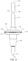
FIG. 8 is a perspective view of a spindle nozzle in accordance with one embodiment;
FIG. 9 is a side view of the spindle nozzle of FIG. 12 in accordance with one embodiment;
FIG. 10 depicts a side cutaway view of the spindle module of FIG. 3 in accordance with one embodiment;
FIG. 11 depicts a front view of the spindle module of FIG. 3 with the first z-axis motor actuated in accordance with one embodiment;
FIG. 12A depicts a perspective view of the spindle module of FIG. 3 with the first z-axis motor actuated in accordance with one embodiment;
FIG. 12B depicts a perspective view of a portion of the spindle module of FIG. 12A enlarged at circle B in accordance with one embodiment;
FIG. 13A depicts a perspective view of the spindle module of FIG. 3 with the first z-axis motor actuated in accordance with one embodiment;
FIG. 13B depicts a perspective view of a portion of the spindle module of FIG. 13A enlarged at circle C in accordance with one embodiment;
FIG. 14 is a perspective view of a spindle bank in accordance with one embodiment; and
FIG. 15 is a perspective view of the spindle bank of FIG. 14 with a plurality of spindle modules attached in accordance with one embodiment.
DETAILED DESCRIPTION
A detailed description of the hereinafter described embodiments of the disclosed apparatus and method are presented herein by way of exemplification and not limitation with reference to the Figures.
Referring to FIG. 1, an assembly machine 10 is shown. The assembly machine 10 is a pick-and-place machine configured to assemble printed circuit boards (PCB's) in the embodiment shown. For example, the assembly machine may be an advanced packaging assembly machine, a component assembly machine, or the like. In other embodiments, the features described herein may be applied to various other assembly machines such as odd form assembly machines (OFA), or the like. The Assembly machine 10 includes a frame 12 providing structure a body 14 having covers 16 a, 16 b. The frame 12 may include a plurality of legs upon which the assembly machine 10 is configured to stand. The assembly machine 10 includes a plurality of feeder banks 18 a, 18 b. A plurality of feeders 20 are disposed (shown in FIG. 2A), attached, or otherwise mounted to each of the feeder banks 18 a, 18 b. The feeders 20 may each include a plurality of electronic components that the assembly machine 10 is configured to pick-and-place onto a PCB to assemble or at least partially assemble the PCB. The assembly machine 10 further includes a board handling opening 22. A board handling track 24 may extend within the body 14 of the assembly machine 10 extending between the opening 22 and another opening on the opposing side of the assembly machine (not shown). The board handling track 24 may be configured to receive a PCB or another unfinished product and transport the PCB to a placement location within the body of the assembly machine 10 for assembly. The assembly machine 10 is shown further including operator interface and control displays 26 a, 26 b, one on each side. The display 26 may be configured to receive user or operator inputs and display information necessary or useful to a user or operator. While the features of the assembly machine 10 shown are one exemplary embodiment, aspects of the invention described herein are applicable to various other types of assembly machines as will be apparent to those skilled in the art.
Referring now to FIG. 2A, the assembly machine 10 is shown with the covers 16 a, 16 b removed exposing an interior 28 of the assembly machine 10. The assembly machine 10 includes two additional feeder banks 18 c, 18 d disposed on the opposite side of the body 14 as the feeder banks 18 a, 18 b. The board handling track 24 may be located between the feeder banks 18 a, 18 b and 18 c, 18 d. The board handling track 24 may be configured to provide an unfinished product such as a PCB to a placement station 30 located along the track 24.
The assembly machine 10 may facilitate movement of components in three movement axes: an x-axis, a y-axis and a z-axis. Hereinafter, the x-axis may be an axis extending parallel to the board handling track 24. The y-axis may be perpendicular to the x-axis and the board handling track 24. The z-axis may be an up and down or vertical axis. The assembly machine 10 may include a plurality of movement axes 32, 34, 36, 38 for facilitating movement in the x-axis and the y-axis. In particular, the assembly machine 10 may include a first movement axis 32 and a second movement axis 34 that are configured to facilitate movement in the y-axis. The assembly machine 10 may include a third movement axis 36 and a second movement axis 38 that are configured to facilitate movement in the x-axis. The first and the second movement axis 32 may extend along a depth of the machine between a first side 40 and a second side 42. The first side 40 is the side of the assembly machine 10 proximate the first and second feeder banks 18 a, 18 b. The second side 42 is the side of the assembly machine 10 proximate the third and fourth feeder banks 18 c, 18 d. The third and fourth movement axes 36, 38 are shown connected to the first and second movement axes 32, 34 and extend there between. During operation of the assembly machine 10, the third and fourth movement axes 36, 38 are configured to each independently move along the first and second movement axes 32, 34 to provide for movement in the y-axis. A spindle bank 100 a, 100 b is shown movably attached to each of the third and fourth movement axes 36, 38, respectively. The spindle banks 100 a, 100 b may each be configured to move along the x-axis by moving along the respective third and fourth movement axes 36, 38. In other embodiments, the assembly machine 10 may be a single-moveable axis machine. For example, there may be a single x-axis and a single y-axis connectable to the assembly machine, rather than two of each as shown in the embodiment in the Figures.
With the movement axes 32, 34, 36, 38, the spindle banks 100 a, 100 b within the assembly machine 10 are configured for both x-axis and y-axis freedom of operation within the interior 28. This allows the spindle banks 100 a, 100 b to move back and forth to and from the feeder banks 18 a, 18 b, 18 c, 18 d and the placement station 30. This is accomplished by both the movement of the spindle banks 100 a, 100 b along the respective third and fourth movement axes 36, 38, and the movement of the third and fourth movement axes 36, 38 along the first and second movement axes 32, 34. Other forms of x-axis and y-axis movement within the assembly machine 10 are contemplated and the movement axes shown are for exemplary purposes.
Referring now to FIG. 2B, a perspective view of a portion of the assembly machine 10 enlarged at circle A (from FIG. 2A) is shown. The enlarged portion shows the spindle bank 100 a having a base 110 and a bearing system 112. The base 110 may be a body, housing, structure or the like. The base 110 may include a plurality of mount locations 114 a, 114 b, 114 c, 114 d, 114 e, 114 f, 114 g, 114 h each configured to receive a spindle module 200 a, 200 b, 200 c, 200 d, 200 e, 200 f, 200 g, 200 h, respectively. The spindle modules described herein may be pick-and-place spindle modules particularly configured for receiving spindle and nozzle combinations that are configured to pick, place, or otherwise manipulate electronic components for printed circuit board assembly and picking and placement processes. The spindle modules described herein may also be utilized for other assembly processes where one or more rotatable and/or descendible manipulating spindles are necessary to perform at least a portion of an assembly process for assembling an unfinished product.
The bearing system 112 may be a system that provides for movement of the spindle bank 100 a along the third movement axis 36. The bearing system 112 may include wheels to facilitate movement between the spindle bank 100 a and the movement axis 36. In other embodiment, the bearing system 112 may include magnets to facilitate magnetic movement between the spindle bank 100 a and the third movement axis 36. The third movement axis 36 may include a track structure on the underside (not shown) that may cooperate with a track structure bearing system of the spindle bank 100 a. For example, the spindle bank 100 may include track runner bearings configured to cooperate with a track of the third movement axis 36. A motor or other movement creating mechanism may provide for controlled powered movement of the spindle bank 100 along the third movement axis 36. The motor may be located on the spindle bank itself 100, or may be located on the third movement axis 36. Thus, the spindle bank 100 may include one or more electrical ports, connectors or the like to connect to an electrical system of the assembly machine 10 to thereby provide electrical power to the spindle bank 100. The spindle bank 100 may utilize this electricity to power a motor or otherwise provide motion, movement, or acceleration of the spindle bank 100 relative to the third movement axis 36.
The mount locations 114 a, 114 b, 114 c, 114 d, 114 e, 114 f, 114 g, 114 h may provide for modularity in the spindle bank 100 a such that the spindle bank 100 a may be operable with each of the spindle modules 200 a, 200 b, 200 c, 200 d, 200 e, 200 f, 200 g, 200 h attached or with a single one of the spindle modules. In other words, the spindle bank 100 a may be operable no matter how many of the spindle modules 200 a, 200 b, 200 c, 200 d, 200 e, 200 f, 200 g, 200 h are installed into the mount locations 114 a, 114 b, 114 c, 114 d, 114 e, 114 f, 114 g, 114 h. If one of the spindle modules 200 a, 200 b, 200 c, 200 d, 200 e, 200 f, 200 g, 200 h breaks or is need of repair, the spindle bank 100 a may be operable. Further, while the spindle modules 200 a, 200 b, 200 c, 200 d, 200 e, 200 f, 200 g, 200 h shown are all the same or similar, the mount locations 114 a, 114 b, 114 c, 114 d, 114 e, 114 f, 114 g, 114 h may each be configured to receive different types of spindle modules with different types of spindles, nozzles and the like. The mount locations 114 a, 114 b, 114 c, 114 d, 114 e, 114 f, 114 g, 114 h may each have the same physical mounting properties such that the spindle modules 200 a, 200 b, 200 c, 200 d, 200 e, 200 f, 200 g, 200 h may each include the same mounting properties, making each module interchangeably attachable to any mount location. In other embodiments, the spindle bank 100 a may include mount locations that have different physical attachment properties to provide for attachment of modules having different attachment mechanisms or properties than other modules attachable in other mount locations on the spindle bank 100 a.
Referring now to FIG. 3, a spindle module 200 is shown. The spindle module may be the same as one of the spindle modules 200 a, 200 b, 200 c, 200 d, 200 e, 200 f, 200 g, 200 h shown in FIG. 2B. The spindle module 200 is shown including a modular body structure 210. The modular body structure may include a first body structure 212 and a second body structure 214 mounted or attached to the first body structure 212. The second body structure 214 includes a first receiving location 216 configured to receive a first spindle 300 a, and a second receiving location 218 configured to receive a second spindle 300 b.
The spindle module 200 further includes a first z-axis motor 220 and a second z-axis motor 222, each mounted to the second body structure 214. The first z-axis motor 220 may be configured to move the first spindle 300 a in the z-axis direction. Similarly, the second z-axis motor 222 may be configured to move the second spindle 300 b in the z-axis direction. The spindle module 200 further includes a first theta motor 224 and a second theta motor 226. The first theta motor 224 may be configured to rotate the first spindle 300 a in a theta (θ) rotational axis. The second theta motor 226 may be configured to rotate the second spindle 300 b in the theta (θ) rotational axis. The first and second theta motors 224, 226 may be configured to provide theta axis rotation in either directions. Thus, the spindle module 200 may provide for movement in the z-axis and rotational movement in the theta (θ) rotational axis. The spindle module 200 may provide for independent movement for each of the first and second spindles 300 a, 300 b.
The spindle module 200 may further include an air distribution system that includes one or more valves 228, 230, first and second air distribution ports 232, 234 (shown in FIGS. 12A and 13A), along with two airflow tubes 236 (one shown), each providing vacuum generating airflow to the first and second spindles 300 a, 300 b. The air distribution system may further include a pneumatic connector 256 (one shown) on each side. The first and second air distribution ports 232, 234 may each be configured to receive air from an air distribution system of the assembly machine 10 and deliver the received air to the first and second spindles 300 a, 300 b. After receiving the air at the air distribution ports 232, 234, internal airflow tubes (not shown) may provide this airflow to the pneumatic connectors 256. The airflow tubes 236 may connect to the pneumatic connectors 256 by elongating the airflow tubes or using another tube that connects the pneumatic connectors 256 to the airflow tubes 236, respectively. In the embodiment shown, the first valve 228 is housed within a widened portion of the first body structure 214, and may provide for air-kiss forward air pressure. The second valve 230 is also shown to be housed within a widened portion of the first body structure 214, and may be a valve for providing vacuum pressure for picking up a component with the first and second spindles 300 a, 300 b.
The spindle module 200 may have a first outer body 238 a and a second outer body 238 b mounted to the first body structure 212 with several screws. The outer bodies 238 a, 238 b may be a first circuit board and a second circuit board. As shown, the spindle module 200 includes an electrical distribution system including a second circuit board assembly 251 containing a plurality of electrical distribution ports 242 a, 242 b configured to receive electricity from the assembly machine 10 and/or the spindle bank 100 a or 100 b when attached and deliver the received electricity to the first and second z- axis motors 220, 222 and the first and second theta motors 224, 226. When the spindle module 200 is attached to the assembly machine 10, each of the electrical distribution ports 242 a and 242 b may be attached to electrical connectors of the assembly machine 10 or spindle bank 100 a or 100 b.
In one embodiment, the ports 240 a, 240 b may be configured to deliver electricity from the distribution ports 242 a and 242 b to the circuit board assembly 238 a and 238 b and to electrical connectors 252, 254, 257. It should be understood that duplicate electrical connectors to the electrical connectors 252, 254 and 257 are found on the opposite side of the outer body 238 a. Thus, electricity may travel through the port 242 a through 240 a and 238 a and through the electrical connector 257, and through a cable (not shown) to the first z-axis motor 220. Similarly, electricity may travel through the port 242 a, through 240 a and 238 a through the electrical connector 252 and through a cable (not shown) to the first theta motor 224. Connector 254 may be used to connect to a spindle module optical detector 550 (described herein below, cable not shown) to the motion control chip 250 located on 238 a. This electrical arrangement may be duplicated on the other side with respect to the printed circuit board second outer body 238 b.
The spindle module 200 may include one or more mechanical attachment mechanisms to facilitate attachment of the spindle module 200 to the assembly machine 10, for example to a spindle bank such as one of the spindle banks 100 a, 100 b. In the embodiment shown, the mechanical attachment mechanisms comprise a first threaded screw 246 a and a second threaded screw 246 b. In one embodiment, the mechanical attachment mechanism may be capable of attachment with only a non-powered hand tool such as a screw driver, Allen wrench, wrench, or the like. In the embodiment shown, the first and second threaded screws 246 a, 246 b may be turned by an Allen wrench at bolt heads 248 a, 248 b (shown in FIG. 5). Further, the tightening of the threaded screws 246 a, 246 b may be the only procedure or step required to attach the spindle module 200 to one of the spindle banks 100 a, 100 b. Similarly, the loosening of the threaded screws 246 a, 246 b may be the only procedure or step required to unattach or remove the spindle module 200 from one of the spindle banks 100 a, 100 b.
The attachment of the spindle module 200 may be completed, executed or performed such that the air distribution ports are connectable to receive air from the assembly machine 10 and/or the spindle bank 100 a or 100 b, and the electrical distribution port is configured to receive electricity from the assembly machine 10 and/or the spindle bank 100 a or 100 b. The spindle module 200 may not be attachable directly to any movement axis of the assembly machine 10, such as the first, second, third or fourth movement axes 32, 34, 36, 38. Instead, the spindle module 200 may be attachable to one of the spindle banks 100 a, 100 b which in turn may be attachable to one or more of the first, second, third or fourth movement axes 32, 34, 36, 38.
The spindle module 200 may further include a first motion control chip 250 attached to the first body structure 212 proximate the second body structure 214 and the motors 220, 222, 224, 226. An opposite side of the first body structure 212 may include a second motion control chip (not shown) in a mirrored location as the first motion control chip 250. The first motion control chip 250 may each be configured to control the first z-axis motor 220 and the first theta motor 224. The motion control chip 250 may thus be a dedicated control chip, processor, or the like, configured to control only one of the two spindles 300 a, 300 b contained in the spindle module 200, in particular the first spindle 300 a. The second motion control chip may be a dedicated control chip, processor, or the like configured to control the second spindle 300 b. Each of the first motion control chip 250 and the second motion control chip may be configured to control speed, acceleration and position of the respective first and second z- axis motors 220, 222 and the first and second theta motors 224, 226. Further, each of the first motion control chip 250 and the second motion control chip may be configured to create an independent and/or separate motion control profile for each of the first and second spindles 300 a, 300 b, respectively.
Referring now to FIGS. 4 and 5, a perspective view and side view, respective, of the second body structure 214 is shown prior to attachment with the first body structure 212. The second body structure 214 includes a middle structural portion 258, an upper structural portion 260 and a lower structural portion 262. The second body structure 214 may be a machined metallic component consistent with the dimensions shown. The second body structure 214 may be configured to receive for attachment the first and second z- axis motors 220, 222, and may include the support structure to allow for moveable attachment along the z-axis of the first and second theta motors 224, 226, as described in more detail herein below.
The middle structural portion 258 may include an opening 263 or bore configured to receive the second threaded screw 246 b and the head 248 b thereof. The middle structural portion 258 may include a square or rectangular cross section extending in the direction of the opening 263 and surrounding the opening 263. A back end of the middle structural portion 258 may include extending support flanges 264 a, 264 b configured for supporting the second body structure 214 when mounted to the first body structure 212.
The upper structural portion 260 extends upward from the middle structural portion 258. The upper structural portion 260 includes a depth extending from a front end 269 along the y-axis. The upper structural portion 260 includes an upper rectangular removed portion 274 configured to reduce the weight of the second body structure 214. The upper structural portion 260 includes a first z-axis motor mount face 266 and a second z-axis motor mount face 268. The first z-axis motor mount face 266 is shown flush to the front end 269 of the upper structural portion 260 while the second z-axis motor mount face 268 extends from a middle point along the depth of the upper structural portion, the middle point being closer to the front end 269 than the opposing rear end. The first z-axis motor mount face 266 and the second z-axis motor mount face 268 may be spaced apart along both the x-axis and the y-axis. Further, the first z-axis motor mount face 266 may be facing a first direction while the second z-axis motor mount face 268 may be facing a second direction that is opposite the first direction. The first and second z-axis mount faces 266, 268 may each include a removed portion 276 a, 276 b configured to reduce the weight of the second body structure 214.
In one embodiment, the first and second mount faces 266, 268 may be located such that when mounted the vertical z-axes of first and second z- axis motors 220, 222 are spaced at least 18 mm apart. In other embodiments, the first and second mount faces 266, 268 may be located such that when mounted the vertical z-axes of first and second z- axis motors 220, 222 are spaced no more than 18 mm apart. In yet other embodiments, the first and second mount faces 266, 268 may be located such that when mounted the vertical z-axes of the first and second z- axis motors 220, 222 are spaced at least 16 mm apart. In one embodiment, the first and second mount faces 266, 268 may be located such that when mounted the vertical z-axes of the first and second z- axis motors 220, 222 are spaced at least 18 mm apart in total and at least 10 mm apart along the x-axis. Thus, the first and second mount faces 266, 268 may be located such that when mounted the vertical z-axes of the first and second z- axis motors 220, 222 are spaced on a diagonal relative the x-axis and the y-axis.
Extending to the top of the upper structural portion 260 is an upper stanchion 270, post, or the like configured to provide for a second attachment location. The upper stanchion 270 may include another opening 272 or bore configured to receive the first threaded screw 246 a and the head 248 a for attachment of the combined modular body structure 210 to the spindle bank 100 a, 100 b.
The lower structural portion 262 extends downward from the middle structural portion 258. The lower structural portion 262 includes a depth extending from a front end 277 along the y-axis. The lower structural portion 262 includes a lower rectangular removed portion 273 configured to reduce the weight of the second body structure 214. The lower structural portion 262 may be a U-shaped structure extending from the middle portion 258. The front end 277 of the U-shaped structure of the lower structural portion 262 includes a first linear track 278 mounted or otherwise attached to a front surface and a second linear track 280 mounted or otherwise attached to an opposing back surface such that the first linear track 278 and the second linear track 280 each extend along the z-axis.
A first body 282 is shown attached to the first linear track 278 and a second body 284 is shown attached to the second linear track 280. As shown in FIGS. 7-8 and described herein below, the first body 282 is operably connected to the first z-axis motor 220 such that the first body 282 moves along the first linear track 278 when the first z-axis motor 220 is actuated. Similarly, the second body 284 is operably connected to the second z-axis motor 222 such that the second body 284 moves along the second linear track 280 when the second z-axis motor 222 is actuated. The first and second bodies 282, 284 may each be linear bearing systems configured to integrate with the first and second linear tracks 278, 280, respectively. In one embodiment, the first and second bodies 282, 284 may be configured to slidably move along the first and second linear tracks 278, 280, respectively. In other embodiments, the first and second bodies 282, 284 may house rollers or wheels configured to facilitate movement along the first and second tracks 278, 280. To attach the first and second bodies 282, 284 to the first and second tracks 278, 280, respectively, the first and second bodies 282, 284 may be slid into the track from the bottom. Once the first and second bodies 282, 284 are operably connected to the first and second z- axis motors 220, 222, respectively, the downward z-axis motion of the first and second bodies 282, 284 may be restricted by the movement of the first and second z- axis motors 220, 222 in order to securably attach the first and second bodies 282, 284 onto the first and second tracks 278, 280.
Referring now to FIG. 6, a partially exploded view of the second body structure 214 is shown having the first z-axis motor 220 and the second z-axis motor 222 already attached, the first theta motor 224 and the second theta motor 226 disassembled from the second body structure 214, and the first and second spindles 300 a, 300 b disassembled from the first and second receiving locations 216, 218, respectively. A third body structure 286 is shown attached to the first body 282 and a fourth body structure 288 is shown attached to the second body 284. The third and fourth body structures 286, 288 are shown attached to the first and second bodies 282, 284 through screws or bolts 290 a, 290 b which may be threadably received by openings 291 a, 291 b (shown in FIG. 4) in the first and second bodies 282, 284. The third and fourth body structures 286, 288 may be configured for attaching the first and second theta motors 224, 226 to the movable first and second bodies 282, 284. In this manner, the first and second theta motors 224, 226 may be operably connected to the first and second bodies 282, 284, respectively. The third and fourth body structures 286, 288 may include the first and second receiving locations 216, 218, respectively for receiving the first and second spindles 300 a, 300 b. Further, the third and fourth body structures 286, 288 may include a location at the top that interfaces with and/or otherwise attaches to an extending portion of the z- axis motor 220, 222.
Each of the third and fourth body structures 286, 288 may include a theta motor attachment location 292, 294 configured to receive the first and second theta motors 224, 226, respectively. The theta motor attachment locations 292, 294 may each be semi-circular in shape. The theta motor attachment locations 292, 294 may be offset from the receiving locations 292, 294, respectively, such that motor drive gears 295, 296 of the first and second theta motors 224, 226 may be meshed with theta gears 310 of the spindle 300 a, 300 b. In one embodiment, the first receiving location 216 and the second receiving 218 location spaced apart by a spacing S equal to or less than 10 mm. In other embodiments, the spacing S may be equal to or less than 8 mm. In still other embodiments, the spacing may be equal to or less than 12 mm.
Referring now to FIGS. 7A and 7B, a mechanism and method for connecting the first and second linear tracks 278, 280 to the second body structure 214 is shown. In particular, FIG. 7A shows a side view of the spindle module 200. FIG. 7B shows a cross sectional view of the second body structure 214 of the spindle module 200 at a location where the first and second linear tracks 278, 280 are connected, taken at arrows A-A. As shown in FIG. 7B, the first linear track 278 and the second linear track 280 are attached to the lower structural portion 262 of the second body structure 214 of the modular body structure 210 of the spindle module 200 with a set screw 297 extending between a first nut 298 a and a second nut 298 b. The set screw 297 may include exterior threads as shown. Each of the first and second nuts 298 a, 298 b may include an internally threaded nut body 299 a, 299 b configured to receive the exterior threads of the set screw 297.
The first and second linear tracks 278, 280 may include bores 289 a, 289 b, configured to receive a heads 293 a, 293 b, respectively, of the first and second nuts 298 a, 298 b. In particular, the first linear track 278 may include the first bore 291 a configured to receive the first head 293 a of the first nut 298 a when tightened such that the first nut 298 a does not interfere with movement of the first body 282 on the first linear track 278. Similarly, the second linear track 280 may include a second bore 291 b configured to receive the second head 293 b of the second nut 298 b when tightened such that the second nut 293 b does not interfere with movement of the second body 284 on the second linear track 280.
To connect the first and second linear tracks 278, 280 to the second body structure 214, the process includes inserting the set screw 297 into an opening in each of the first and second linear tracks 278, 280 while aligned with an opening of the second body structure 214, then inserting the nuts 298 a, 298 b such that the internally threaded nut body 299 a, 299 b engages with the external threads of the set screw 297. Next, the process includes tightening the first and second nuts 298 a, 298 b until tight. In one embodiment, only a single set screw and nut combination may be required to fully attach the first and second linear tracks 278, 280. In another, a second set screw may extend between a third nut and a fourth nut at a spaced apart location from the first set screw 297, the first nut 298 a, and the second nut 298 b. An embodiment having two set screws is shown in the Figures (e.g. FIG. 4) where two heads 293 a of the set screws are shown recessed in the track, one at a top of the linear track 278 and one at the bottom of the linear track 278.
Referring now to FIGS. 8 and 9, a spindle 300 is shown. In particular, FIG. 8 shows a perspective view of the spindle 300 and FIG. 9 shows a side view of the spindle. The spindle 300 may include the same features as the spindles 300 a, 300 b. The spindle 300 includes a theta gear 310, a shaft 312 and a nozzle tip 314. The spindle 300 may extend between a first lower end 328 and a second upper end 330.
The spindle 300 may be considered a spindle-nozzle combination. The nozzle tip 314 is configured to contact an electronic component for manipulation of the electronic component. Additionally, the spindle 300 may include the rotatable shaft 312 and the theta gear 310 to facilitate rotation. The spindle 300 may be configured for interchangeability on, or removably attachable to, a dispensing or pick-and-place head (such as the spindle bank 100 and the spindle module 200 combination). The spindle 300 may be found in a nozzle bank of the assembly machine 10 when it is not attached to the spindle module 200 and/or spindle bank 100.
The spindle 300 may be configured to provide vacuum suction to the electronic component through the nozzle tip 314 to allow for the picking up, or other manipulation, of electronic components by the nozzle tip 314. To provide airflow or a vacuum force to the nozzle tip 314, the shaft 312 may include an outer body 316 having a hollow interior 318. The spindle 300 may be configured to provide an airkiss outward airflow through the nozzle tip 314 to the electronic component to facilitate placement of electronic components. In other embodiments, other types of nozzles may be contemplated for the spindle 300, such as nozzles configured to provide a material to an unfinished product.
The theta gear 310 may be disposed onto the shaft 312. The theta gear 310 may include a plurality of teeth 320 evenly disposed about the circumference of the theta gear 310. The teeth 320 of the theta gear 310 may be configured to engage with a theta motor such as one of the theta motors 224, 226. For example, the teeth 320 may be configured to engage with a motor drive gear, such as one of the motor drive gears 295, 296, of the theta motors 224, 226.
The shaft 312 may be cylindrical in shape. The theta gear 310 may be secured to, attached to, or otherwise integrated with, the shaft 312 such that rotation of the theta gear 310 by a motor drive gear also rotates the shaft 312. In some embodiments, the theta gear 310 may be a separately manufactured component from the shaft 312. The theta gear 310 may include a circular inner opening configured to receive the shaft 312.
The outer body 316 of the rotatable shaft 312 includes a first opening 322 configured to receive airflow into the hollow interior 318. For example, the airflow tube 236 of the spindle module 200 may be configured to deliver airflow through the first opening 322 into the hollow interior. The outer body 316 of the rotatable shaft 312 includes a second opening 324 configured to receive airflow into the hollow interior 318. The airflow tube 236 of the spindle module 200 may be configured to deliver airflow through the second opening 324 into the hollow interior. The second opening 324 may be disposed on an opposite side of the rotatable shaft 312 than the first opening 322. While the embodiment shown in FIGS. 8 and 9 includes two openings 322, 324, more or less openings are contemplated. As shown, the each of the first and second openings 322, 324 may be disposed about the outer body 316 of the rotatable shaft 312 at a point along a length of the shaft.
The theta gear 310 may further include an upper surface 326 facing the second upper end 330, and a lower surface 332 facing the first lower end 328. The theta gear 310 may include an outer circumference with the teeth 320 disposed along the outer circumference. The theta gear 310 may further include a circumferential ridge 334 extending from the upper surface 326 toward the first lower end 328. The circumferential ridge 334 may be a ring, protrusion, or the like, and may be located between the outer circumference of the theta gear 310 and the shaft 312.
The theta gear 310 may further include a lower base 336 and an upper base 338. The lower base 336 may extend from the lower surface 332 toward the first lower end 328 of the spindle 300. The lower base 336 may be located proximate the opening of the theta gear 310 and may extend along a length of the opening of the theta gear 310 and along a length of the shaft 312. The lower base 336 and the upper base 338 may be configured to provide support for the attachment of the theta gear 310 to the shaft 312.
In one embodiment, the shaft 312 may be made of a magnetic material to facilitate magnetic attachment of the spindle 300 to a receiving location, such as one of the receiving locations 216, 218, of a dispensing head or pick-and-place head such as the spindle module 200 and/or the spindle bank 100. The magnetic material may provide for removable attachment of the spindle 300 to the dispensing head or pick-and-place head, as described hereinbelow.
The spindle 300 is shown as a spindle-nozzle combination that includes a toothed arrangement for being driven by a tooth drive gear. However, the spindle 300 may also be a spindle-nozzle combination where the theta gear is a magnetic gear rather than a toothed gear. A magnetic theta gear may be driven by a magnetic theta motor. Whatever drive mechanism utilized the spindle 300 may include a nozzle and an integrated means to provide for rotation of the nozzle.
Referring now to FIG. 10, a side cutaway view of the spindle module 200 of FIG. 3 is shown. In particular, FIG. 10 shows the attachment of the first z-axis motor 220 to the third body structure 286. It should be understood that the features that are described hereinbelow as shown with respect to the first z-axis motor 220 and the third body structure 286 may be applicable to the second z-axis motor 222 connecting to the fourth body structure 288.
Each of the first and second z- axis motors 220, 222 includes a movable shaft 516 a, 516 b, respectively, each configured to move relative to the body of the motor. Each of the first and second z- axis motors 220, 222 includes a spring 518 a, 518 b proximate a cap 520 a, 520 b. The springs 518 a, 518 b may be configured to return the movable shaft 516 a, 516 b to the start position after actuation by the z- axis motor 220, 222. The top end of each of the shafts 516 a, 516 b is connected to the respective caps 520 a, 520 b by a threaded feature of the cap being inserted into a threaded bore of the shafts 516 a, 516 b. A threaded set screw 514 may be located at the bottom of each of the shafts 516 a, 516 b connecting the shaft to the third and fourth body structures 286, 288, respectively. Thus, when the z- axis motors 220, 222 are actuated and the shafts 516 a, 516 b displace downward, so do the respective attached body structures, which includes the respective nozzles 300 a, 300 b, and the respective theta motors 224, 226.
Furthermore, the first receiving location 216 is shown after having received the first spindle 300 a into a bore of the first receiving location 216. The first receiving location 216 and the shaft 312 of the first spindle 300 a may include a relatively tight tolerance to allow for z-axis sliding and rotation of the shaft 312 without other movement. The shaft 312 of the first spindle 300 a may be magnetic and may be attracted to a magnet 510 located or disposed within the third body structure 286. This may create a holding force to retain the first spindle 300 a within the first receiving location 216. However, this holding force may be overcome by a greater force if it is desired for the first spindle 300 a to be removed from the first receiving location 216. In this manner, the first spindle 300 a may be removably attachable to the first receiving location 216. As shown a spindle spring 512 may be housed within the third body structure 286. This spindle spring 512 may provide a small amount of spring movement at the moment of pickup and/or placement of a component by the spindle 300 a, when the spindle 300 a is resisted by the upward force from the unmovable feeder bank (during pickup) and unfinished product or PCB (during placement. In other embodiments not shown, the spindle spring 512 may be replaced by a magnet that provides a resistive magnetic force on a corresponding magnet of the spindle 300 a.
FIG. 11 depicts a front view of the spindle module 200 with the first z-axis motor 220 actuated. As shown, the second z-axis motor 222 remains in the upward and non-actuated position. When actuated, the shaft 516 a and spring 518 a are compressed. When actuated, the shaft 518 a then protrudes from the bottom of the body of the z-axis motor 220. An attachment location 522 a between the shaft 518 a and the third body structure 286 is thereby moved down, moving down the first body 282, the first theta motor 224, the first receiving location 216 and the first spindle 300 a. Meanwhile, an attachment location 522 b between the shaft 518 b and the fourth body structure 288 remains stationary, along with the second body 284, the second theta motor 226, the second receiving location 218 and the second spindle 300 b.
FIG. 12A depicts a perspective view of the spindle module 200 with the first z-axis motor 220 actuated and having a circle B drawn around a portion of the spindle 300 a. FIG. 12B depicts a perspective view of a portion of the spindle module 200 enlarged at the circle B. The enlarged view from FIG. 12B shows a spindle module optical detector 550 extending from the third body structure 282 attached to the first body 282. The optical detector 550 may be configured to detect upward movement of the received first spindle 300 a relative to the first body 282 and the third body structure 282. It should be understood that the spindle module 200 may include a second optical detector positioned in the same manner detecting movement of the second received spindle 300 b.
As shown in FIG. 12B, the spindle 300 a is in a resting downward position before the spindle 300 a contacts an electronic component for picking up, or before the spindle 300 a contacts the PCB or other unfinished product during placement. During this resting position, the teeth 320 of the spindle 300 a mesh with the teeth of the first theta motor drive gear 295. Further, the circumferential ridge 334 of the first spindle 300 a does not extend into an opening 552 located between a first end 554 and a second end 556 of the optical sensor 550. The first end 554 of the optical sensor 550 may include an optical light beam generator 558 and the second end 556 of the optical sensor 550 may include an optical light detector. When the circumferential ridge 334 is positioned in the opening 552, the circumferential ridge 334 may break the beam. This may be configured to immediately detect when touchdown has occurred during pickup and/or placement.
FIG. 13A depicts a perspective view of the spindle module 200 with the first z-axis motor 220 actuated and having a circle C drawn around a portion of the spindle 300 a. FIG. 13B depicts a perspective view of a portion of the spindle module 200 enlarged at circle C. As shown in FIG. 13B, the spindle 300 a has now been moved upward relative to the first body 282 and the third body structure 282. Thus, the circumferential ridge 334 is positioned in the opening 552, thereby breaking the beam of the optical sensor 550. It should further be noted that the first theta motor drive gear 295 includes a height that is large enough to maintain contact with the teeth 320 of the nozzle 300 a during motion of the nozzle 300 a relative to the first theta motor drive gear 295. In one embodiment, the first theta motor drive gear 295 may include a height that is larger than the maximum movement allowable between the spindle 300 a and the first body 282 and the third body structure 282.
Referring first to FIG. 14, the spindle bank 100 having a single one of the spindle modules 200 attached. The spindle bank 100 includes the base 110 and the mounting locations 114 a, 114 b, 114 c, 114 d, 114 e, 114 f, 114 g, 114 h. In the embodiment shown, the base 110 includes eight of the mounting locations 114 a, 114 b, 114 c, 114 d, 114 e, 114 f, 114 g, 114 h. In other embodiments, more or less mounting locations are contemplated. For example, a spindle bank may have as little as a single mounting location, or as many mounting locations as would, when attached to the spindle bank 100, span across half the width of the assembly machine, minus half the width of the intended unfinished product the assembly machine is intended to at least partially assemble. Such an arrangement would enable even the left and rightmost spindles in the spindle module to reach each point along the x-axis of the unfinished product.
Each of the plurality of mount locations 114 a, 114 b, 114 c, 114 d, 114 e, 114 f, 114 g, 114 h are configured to receive a mountable spindle module, such as the mountable spindle module 200 as shown. The spindle bank 100, when combined with one or more spindle modules 200 may be a dispensing head or pick-and-place head for the assembly machine 10. Unlike typical dispensing heads and pick-and-place heads, the spindle bank 100 may provide a modular design for simple mechanical attachment and removal of individual modular spindle modules, such as the spindle module 200. The modular nature of the spindle attachment may provide for simpler maintenance when a spindle assembly needs repair. Further, while the spindle module 200 was described hereinabove as an example, various other spindle modules may fit into the spindle bank 100, such as the spindle module 500, shown in FIG. 15. The modularity of the spindle bank 100 and spindle module combination may provide flexibility to the system. The dispensing head defined by the spindle bank 100 and the spindle modules 200, 500 can be easily reconfigured with various spindle modules in whatever configuration needed by an assembly process.
In the embodiment shown, the center of each of the mount locations 114 a, 114 b, 114 c, 114 d, 114 e, 114 f, 114 g, 114 h may be spaced less than 25 mm apart. In other embodiments, the center of each of the mount locations 114 a, 114 b, 114 c, 114 d, 114 e, 114 f, 114 g, 114 h may be spaced less than 20 mm apart. Any spacing is contemplated for the mount locations 114 a, 114 b, 114 c, 114 d, 114 e, 114 f, 114 g, 114 h, but it may be difficult but desirable to reduce the spacing by making each of the spindle modules 200 as thin as possible in order to reduce the size and weight of the spindle bank 100. The above described structure of the spindle module includes various features that provide for thin spindle modules 200 such as the spacing of the z- axis motors 220, 222, the features of the modular body structure 210, and the like.
The spindle bank 100 includes a bearing system 112 comprising a first bearing 116 and a second bearing 118 for attaching the spindle bank 100 to the movement axis of an assembly machine, such as the third movement axis 36 or the fourth movement axis 38. The bearing system 112 may cooperate with a track found in the movement axis 36, 38 of the assembly machine 10. In other embodiments, the bearing system 112 of the spindle bank 100 may include wheels or balls to facilitate movement (not shown). In other embodiments, the bearing system 112 may include other shaped channels for integrating with a track system. In still others, the spindle bank 100 may include a powered bearing system that uses wheels or magnetism to move the spindle bank 100 along the attached movement axis. In others, the axis includes the movement system and the spindle bank 100 is unpowered for the purposes of movement but instead attaches to the axis and is moved by the movement system powered by the axis. In some embodiments, a permanent magnet and coil system may be utilized in which the spindle bank 100 acts as either the permanent magnet(s) or the moveable coil(s), and the axis acts as the other of the permanent magnet(s) or the movable coil(s). The spindle bank 100 may include any system for movably attaching the spindle bank 100 to one or more axis for movement.
The spindle bank 100 further includes an air distribution system including a first inlet 122 and a second inlet 124. The first inlet 122 and the second inlet 124 may each be connected to a tube or other air delivery system from the assembly machine. A channel may extend from the first air inlet 122 with various air outlets 126 a, 126 b, 126 c, 126 d, 126 e, 126 f, 126 g configured to each deliver air to an air distribution port, such as the first air distribution port 232 of the spindle module 200. Similarly, a channel may extend from the second air inlet 124 with various air outlets 128 a, 128 b, 128 c, 128 d, 128 e, 128 f, 128 g configured to each deliver air to an air distribution port, such as the second air distribution port 234 of the spindle module 200. It should be understood two air outlets of the spindle bank 100 are hidden by the attached spindle module 200 in the embodiment shown in FIG. 14. In this manner, the plurality of mount locations 114 a, 114 b, 114 c, 114 d, 114 e, 114 f, 114 g, 114 h may each be configured to deliver air to each of the mountable spindle modules when the modules are mounted.
The spindle bank 100 may further include a power delivery system to delivery electrical power and/or signals to each of the plurality of mount locations 114 a, 114 b, 114 c, 114 d, 114 e, 114 f, 114 g, 114 h. The power delivery system is shown including a set of electrical connectors 132. The set of electrical connectors 132 may be configured to connect to the electrical distribution ports 242 a, 242 b of each of the spindle modules 200. The spindle bank 100 may include one or more electrical input connectors (not shown) to provide electrical power and/or other signals to the spindle bank 100 that are wired to the electrical connectors 130, 132 disposed at the plurality of mount locations 114 a, 114 b, 114 c, 114 d, 114 e, 114 f, 114 g, 114 h.
Each of the plurality of mount locations 114 a, 114 b, 114 c, 114 d, 114 e, 114 f, 114 g, 114 h may include a first threaded attachment location 134 configured to receive the first threaded screw 246 a of the spindle module 200. Each of the plurality of mount locations 114 a, 114 b, 114 c, 114 d, 114 e, 114 f, 114 g, 114 h may include a second threaded attachment location 136 configured to receive the second threaded screw 246 b of the spindle module 200. The first threaded attachment locations 134 and the second threaded attachment locations 136 may each be threaded bores. Thus, as described above, each spindle module 200 may be mounted and removed from the spindle bank 200 by the application or removal of two threaded screws. A hand tool, such as a screwdriver, Allen wrench, wrench, or the like may be the only tool necessary for attachment of the spindle modules 200 to the spindle bank 100.
FIG. 15 shows a plurality of spindle modules 200 a, 200 b, 200 c, 200 d, 200 e, 200 f, 200 g attached, along with the spindle module 500 that is different from the spindle modules 200 a, 200 b, 200 c, 200 d, 200 e, 200 f, 200 g. Thus, the plurality of mount locations 114 a, 114 b, 114 c, 114 d, 114 e, 114 f, 114 g, 114 h includes a first mount locations 114 a configured to receive a first mountable spindle module 500. The plurality of mount locations 114 a, 114 b, 114 c, 114 d, 114 e, 114 f, 114 g, 114 h may include second mount locations 114 b, 114 c, 114 d, 114 e, 114 f, 114 g, 114 h each configured to receive a second mountable spindle module 200. In some embodiments, the first mount location 114 a and the second mount locations 114 b, 114 c, 114 d, 114 e, 114 f, 114 g, 114 h may be structurally the same. In other embodiments, the spindle bank 100 may include structural differences between mount locations. Thus, the first mountable spindle module 500 is different than the second mountable spindle modules 200 a, 200 b, 200 c, 200 d, 200 e, 200 f, 200 g. For example, the first mountable spindle module 500 includes a single spindle and nozzle, while each of the second mountable spindle modules 200 a, 200 b, 200 c, 200 d, 200 e, 200 f, 200 g include two spindle and nozzles. In accommodating different spindle modules, the first mount location 114 a may include at least one different physical property than the second mount locations 114 b, 114 c, 114 d, 114 e, 114 f, 114 g, 114 h. Spindle banks accommodating various different spindle modules with differences in features or physical properties at the mount locations are contemplated.
While not shown, it is also contemplated that the spindle bank 100 includes one or more motion control chips for each of the plurality of mount locations 114 a, 114 b, 114 c, 114 d, 114 e, 114 f, 114 g, 114 h. The embodiment shown includes the motion control chips 250 attached to each of the attachable spindle modules 200. However, in other embodiments, these motion control chips may be found on the spindle bank 100. Whatever the embodiment, the dispensing head or pick-and-place head defined by the combination of the spindle bank 100 and the attached spindle modules 200, 500 may include a number of control chips 250 equal to the number of spindles. In other embodiments, each spindle module 200 includes a single one of the control chips 250 dedicated to the two spindles located on the module.
Various methods are contemplated for assembling unfinished products, or assembling assembly machines, utilizing the assembly machines, dispensing heads, spindles, spindle mounting modules and spindle banks described hereinabove.
For example, a method of assembly may include providing a pick-and-place machine, such as the assembly machine 10, having a pick-and-place head, such as the combination of the spindle banks 100 and one or more of the spindle modules 200. The method may include providing a spindle, such as the spindle 300, for the pick-and-place machine. The method may include attaching the spindle to the pick-and-place head of the pick-and-place machine. The method may include engaging, by a theta gear of the spindle, with a motor, such as the first theta motor 224, of the pick-and-place head. The method may include contacting, by the spindle, an electronic component, or a portion thereof. The method may include manipulating, by the spindle, the electrical component. The method may include removing the spindle from the pick-and-place head of the pick-and-place machine to a spindle bank of the pick-and-place machine. The method may include receiving, by at least one opening in the shaft of the spindle, air flow into a hollow interior of the spindle from an air delivery system of the pick-and-place head and utilizing the airflow during the manipulating. The method may include picking up, with the nozzle, the electrical component using the airflow, and placing, with the nozzle, the electronic component using the airflow. The method may include rotating, with the motor of the pick-and-place head, the theta gear of the spindle and rotating, by the rotating of the theta gear, the shaft and the nozzle tip of the spindle. The method may include breaking, by a circumferential ridge of the spindle, a beam of an optical sensor, such as the optical sensor 550, disposed on the pick-and-place head. The method may include sensing, by the optical sensor, movement by the nozzle relative to at least a portion of the pick-and-place head. The method may include rotating, by the motor, the theta gear by a magnetic force. The method may include receiving, by a magnet of a receiving location of the pick and place head, the shaft such that the magnetic material interacts with the magnet of the receiving location.
Another method of assembly may include providing a pick-and-place machine, such as the assembly machine 10 having a first movement axis, such as the third movement axis 36 or the fourth movement axis 38. The method may include providing a spindle bank, such as the spindle bank 100, for a pick-and-place machine. The method may include mounting, on each of a plurality of mount locations of the spindle bank, a mountable spindle module, such as the spindle module 200, 500, including at least one pick-and-place spindle and nozzle, such as the spindle and nozzle combination 300. The method may include assembling, by the received mountable spindle modules, at least one unfinished product. The method may include distributing air, by an air distribution system of the assembly machine, to the spindle bank, and distributing the air, by a second air distribution system of the spindle bank, to each of the mountable spindle modules after the mounting. The method may include distributing electrical power, by an electrical power distribution system of the assembly machine, to the spindle bank, and distributing the electrical power, by a second electrical power distribution system of the spindle bank, such as the electrical connectors 130, 132, to each of the mountable spindle modules after the mounting. The method may include receiving, by at least one threaded attachment location of the spindle bank such as the threaded attachment locations 134, 136, at least one threaded attachment component of the at least one of the mountable spindle modules, such as the screws 246 a, 246 b. The method may include using, by an installer, only a hand tool and attaching the at least one of the mountable spindle modules to a selected one of the plurality of mount locations. The method may include attaching a bearing system of the spindle bank, such as the bearing system 112, to the first movement axis. The method may include moving the spindle bank along the first movement axis by the pick-and-place machine. The method may include attaching the first movement axis to a second movement axis of the pick-and-place machine, such as the first movement axis 32 and/or the second movement axis 34, and moving the spindle bank along the second movement axis by the pick-and-place machine. The method may include mounting a first mountable spindle module to a first mount location of the spindle bank and mounting the second mountable spindle module to a second mount location, wherein the second mountable spindle module is different than the first and wherein the second mount location includes different physical properties than the first mount location.
Another of assembly may include providing a pick-and-place machine, such as the assembly machine 10, having a first movement axis, such as the third movement axis 36 or the fourth movement axis 38. The method may include providing a spindle bank, such as the spindle bank 100 attached to the pick and place machine such that the spindle bank is movable along the first movement axis. The method may include providing a first pick-and-place spindle module, such as the spindle module 200. The method may include attaching, using a mechanical attachment mechanism such as the screws 246 a, 246 b, the first pick-and-place spindle module to the spindle bank such that an air distribution port, such as one of the air distribution ports 232, 234, is connected to receive air from an element, such as air outlets 126 a, 126 b, 126 c, 126 d, 126 e, 126 f, 126 g of the spindle bank and the electrical distribution port, such as the electrical distribution ports 240 a, 240 b, 242 a, 242 b is connected to receive electricity from an element, such as the electrical connectors 130, 132 of the spindle bank. The method may include receiving, by a receiving location of the modular body structure, a first spindle, such as the spindle 300. The method may include moving, by a first z-axis motor such as the z-axis motor 220, the received first spindle in a z-axis. The method may include rotating, by a first theta motor such as the first theta motor 224, the received first spindle. The method may include delivering, by the air distribution system, received air from the air distribution port to the received first spindle. The method may include delivering, by the electrical distribution system, received electricity from the electrical distribution port to the received first spindle. The method may include moving the spindle bank along the first movement axis and at least partially assembling, by the attached first pick-and-place spindle module, at least one unfinished product. The method may include attaching the first pick-and-place spindle module to the spindle bank with a hand tool. The method may include receiving, by a second receiving location of the modular body structure, a second spindle such as the spindle 300. The method may include moving, by a second z-axis motor such as the second z-axis motor 222, the received second spindle in the z-axis. The method may include rotating, by a second theta motor such as the second theta motor 226, the received second spindle. The method may include delivering, by the air distribution system, received air from the air distribution port to the received second spindle and delivering, by the electrical distribution system, received electricity from the electrical distribution port to the received second spindle. The method may include moving, by the first z-axis motor, a first body, such as the first body 282, along a first linear track, such as the first linear track 278. The method may include moving, by the second z-axis motor, the second body, such as the second body 284, along a second linear track, such as the second linear track 280. The method may include attaching the first linear track and the second linear track to the modular body structure with a set screw, such as the set screw 297 extending between a first nut and a second nut, such as the first and second nuts 298 a, 298 b.
The method may further include controlling, with a first motion control chip of the spindle module, such as the motion control chip 250, the first z-axis motor and the first theta motor. The method may include controlling, with a second motion control chip, the second z-axis motor and the second theta motor.
The method of assembly may also include providing a second pick-and-place spindle module, such as the spindle module 500 or 200. The method may include attaching, using the mechanical attachment mechanism, the second pick-and-place spindle module to the spindle bank such that the air distribution port of the second pick-and-place spindle module is connected to receive air from an element of the spindle bank and the electrical distribution port of the second pick-and-place spindle module is connected to receive electricity from an element of the spindle bank. The method may include receiving, by a receiving location of a modular body structure of the second pick-and-place spindle module, a spindle. The method may include moving, by the first z-axis motor of the second pick-and-place spindle module, the received spindle of the second pick-and-place spindle module in a z-axis. The method may include rotating, by the first theta motor of the second pick-and-place spindle module, the received spindle of the second pick-and-place spindle module. The method may include delivering, by the air distribution system of the second pick-and-place spindle module, received air from the air distribution port of the second pick-and-place spindle module to the received spindle of the second pick-and-place spindle module. The method may include delivering, by the electrical distribution system of the second pick-and-place spindle module, received electricity from the electrical distribution port of the second pick-and-place spindle module to the received spindle of the second pick-and-place spindle module. The method may include at least partially assembling, by the attached second pick-and-place spindle module, the at least one unfinished product. The method may still further include controlling, with a first motion control chip, the first z-axis motor of the first pick-and-place spindle module and the first theta motor of the first pick-and-place spindle module, and controlling, with a second motion control chip, the first z-axis motor of the second pick-and-place spindle module and the first theta motor of the second pick-and-place spindle module.
Methods of assembly may further include providing a pick-and-place head that includes a body structure such as the modular body structure 210 and/or the base 110 of the spindle bank 100, or any other body for a pick-and-place or dispensing head. The method may include providing a plurality of z-axis motors attached to the body structure, each configured to move a spindle in a z-axis and a plurality of theta motors attached to the body structure each configured to rotate a spindle. The method may include providing a plurality of motion control chips each attached to the body structure. The method may include controlling, with each of the plurality of motion control chips, a single one of the plurality of z-axis motors and a single one of the plurality of theta motors, and at least partially assembling, with the pick and place head, an unfinished product. The method may include controlling, with each of the plurality of motion control chips, speed of a single one of the plurality of z-axis motors and a single one of the plurality of theta motors. The method may include controlling, with each of the plurality of motion control chips, acceleration of a single one of the plurality of z-axis motors and a single one of the plurality of theta motors. The method may include controlling, with each of the plurality of motion control chips, position of a single one of the plurality of z-axis motors and a single one of the plurality of theta motors. The method may still further include creating, with each of the plurality of motion control chips, a separate independent motion control profile for each of the plurality of spindles.
Elements of the embodiments have been introduced with either the articles “a” or “an.” The articles are intended to mean that there are one or more of the elements. The terms “including” and “having” and their derivatives are intended to be inclusive such that there may be additional elements other than the elements listed. The conjunction “or” when used with a list of at least two terms is intended to mean any term or combination of terms. The terms “first” and “second” are used to distinguish elements and are not used to denote a particular order.
While the invention has been described in detail in connection with only a limited number of embodiments, it should be readily understood that the invention is not limited to such disclosed embodiments. Rather, the invention can be modified to incorporate any number of variations, alterations, substitutions or equivalent arrangements not heretofore described, but which are commensurate with the spirit and scope of the invention. Additionally, while various embodiments of the invention have been described, it is to be understood that aspects of the invention may include only some of the described embodiments. Accordingly, the invention is not to be seen as limited by the foregoing description, but is only limited by the scope of the appended claims.

Claims (9)

What is claimed:
1. A pick-and-place dispensing head comprising:
a body structure including a first z-axis motor attachment location, a second z-axis motor attachment location, a first linear track and a second linear track;
a first z-axis motor attached to the body structure at the first z-axis motor attachment location;
a second z-axis motor attached to the body structure at the second z-axis motor attachment location;
a first body attached to the first linear track and operably connected to the first z-axis motor such that the first body moves along the first linear track when the first z-axis motor is actuated;
a second body attached to the second linear track and operably connected to the second z-axis motor such that the second body moves along the second linear track when the second z-axis motor is actuated;
a first theta motor operably connected to the first body;
a second theta motor operably connected to the second body;
a first receiving location operably connected to the first body, the first receiving location adapted to receive a first pick-and-place spindle with a tolerance that allows the sliding and rotation of a z-axis shaft of the received first pick-and-place spindle, wherein the first theta motor is configured to rotate the first pick-and-place spindle received in the first receiving location; and
a second receiving location operably connected to the second body, the second receiving location adapted to receive a second pick-and-place spindle with a tolerance that allows the sliding and rotation of a z-axis shaft of the received second pick-and-place spindle, wherein the second theta motor is configured to rotate the second pick-and-place spindle received in the second receiving location,
wherein the first receiving location and the second receiving location are spaced apart along the x-axis,
wherein the first linear track and the second linear track are attached to the body structure with a set screw extending between a first nut and a second nut.
2. The pick-and-place dispensing head of claim 1, wherein the set screw includes exterior threads and wherein each of the first nut and the second nut includes an internally threaded nut body configured to receive the exterior threads of the set screw.
3. The pick-and-place dispensing head of claim 2, wherein the first linear track includes a first bore configured to receive a head of the first nut when tightened such that the first nut does not interfere with movement of the first body on the first linear track, and wherein the second linear track includes a second bore configured to receive a head of the second nut when tightened such that the second nut does not interfere with movement of the second body on the second linear track.
4. The pick-and-place dispensing head of claim 2, wherein the first linear track and the second linear track are attached to the body structure with a second set screw extending between a third nut and a fourth nut.
5. A pick-and-place dispensing head comprising:
a body structure extending in an x-axis, a y-axis perpendicular to the x-axis, and a z-axis perpendicular to the x-axis and the y-axis, the body structure including a first z-axis motor attachment location, a second z-axis motor attachment location, a first linear track extending along the z-axis and a second linear track extending along the z-axis;
a first z-axis motor attached to the body structure at the first z-axis motor attachment location, the first z-axis motor configured to exact movement in the z-axis;
a second z-axis motor attached to the body structure at the second z-axis motor attachment location, the second z-axis motor configured to exact movement in the z-axis;
a first body attached to the first linear track and operably connected to the first z-axis motor such that the first body moves along the first linear track when the first z-axis motor is actuated;
a second body attached to the second linear track and operably connected to the second z-axis motor such that the second body moves along the second linear track when the second z-axis motor is actuated;
a first theta motor operably connected to the first body;
a second theta motor operably connected to the second body;
a first receiving location operably connected to the first body, the first receiving location adapted to receive a first pick-and-place spindle with a tolerance that allows the sliding and rotation of a z-axis shaft of the received first pick-and-place spindle, wherein the first theta motor is configured to rotate the first pick-and-place spindle received in the first receiving location; and
a second receiving location operably connected to the second body, the second receiving location adapted to receive a second pick-and-place spindle with a tolerance that allows the sliding and rotation of a z-axis shaft of the received second pick-and-place spindle, wherein the second theta motor is configured to rotate the second pick-and-place spindle received in the second receiving location,
wherein the first receiving location and the second receiving location are spaced apart along the x-axis and located at a same location along the y-axis, wherein the first z-axis motor and the second z-axis motor are spaced apart along the x-axis and spaced apart on the y-axis.
6. The pick-and-place dispensing head of claim 5, wherein the first receiving location and the second receiving location spaced apart along the x-axis equal to or less than 12 mm.
7. The pick-and-place dispensing head of claim 6, wherein the first z-axis motor and the second z-axis motor are spaced apart equal to or greater than 16 mm.
8. The pick-and-place dispensing head of claim 5, wherein the first receiving location and the second receiving location spaced apart along the x-axis equal to or less than 10 mm.
9. The pick-and-place dispensing head of claim 8, wherein the first z-axis motor and the second z-axis motor are spaced apart equal to or greater than 18 mm.
US16/992,835 2018-02-26 2020-08-13 Dispensing head Active US11382248B2 (en)

Priority Applications (1)

Application Number Priority Date Filing Date Title
US16/992,835 US11382248B2 (en) 2018-02-26 2020-08-13 Dispensing head

Applications Claiming Priority (3)

Application Number Priority Date Filing Date Title
US16/969,751 US11464146B2 (en) 2018-02-26 2018-02-26 Dispensing head, nozzle and method
PCT/US2018/019753 WO2019164532A1 (en) 2018-02-26 2018-02-26 Dispensing head, nozzle and method
US16/992,835 US11382248B2 (en) 2018-02-26 2020-08-13 Dispensing head

Related Parent Applications (2)

Application Number Title Priority Date Filing Date
US16/969,751 Division US11464146B2 (en) 2018-02-26 2018-02-26 Dispensing head, nozzle and method
PCT/US2018/019753 Division WO2019164532A1 (en) 2018-02-26 2018-02-26 Dispensing head, nozzle and method

Publications (2)

Publication Number Publication Date
US20200375074A1 US20200375074A1 (en) 2020-11-26
US11382248B2 true US11382248B2 (en) 2022-07-05

Family

ID=73457819

Family Applications (2)

Application Number Title Priority Date Filing Date
US16/992,835 Active US11382248B2 (en) 2018-02-26 2020-08-13 Dispensing head
US16/992,918 Active US11375651B2 (en) 2018-02-26 2020-08-13 Dispensing head, nozzle and method

Family Applications After (1)

Application Number Title Priority Date Filing Date
US16/992,918 Active US11375651B2 (en) 2018-02-26 2020-08-13 Dispensing head, nozzle and method

Country Status (1)

Country Link
US (2) US11382248B2 (en)

Families Citing this family (2)

* Cited by examiner, † Cited by third party
Publication number Priority date Publication date Assignee Title
DE112018007161T5 (en) 2018-02-26 2020-11-26 Universal Instruments Corporation EQUIPMENT HEAD, NOZZLE AND PROCEDURE
US11382248B2 (en) 2018-02-26 2022-07-05 Universal Instruments Corporation Dispensing head

Citations (70)

* Cited by examiner, † Cited by third party
Publication number Priority date Publication date Assignee Title
US3342396A (en) 1965-03-08 1967-09-19 Basic Products Corp Air spindle for bonding machines
US4611397A (en) 1984-10-09 1986-09-16 Universal Instruments Corporation Pick and place method and apparatus for handling electrical components
US4979286A (en) 1988-05-13 1990-12-25 Hitachi, Ltd. Electric parts mounting apparatus and electric parts mounting method
US5070598A (en) 1989-05-18 1991-12-10 Hitachi, Ltd. Device for mounting electronic parts
US5588195A (en) 1994-09-26 1996-12-31 Fuji Machine Mfg. Co., Ltd. Electronic-component mounting apparatus
CN1170334A (en) 1996-01-29 1998-01-14 三星航空产业株式会社 Component mounting apparatus
US5758410A (en) 1995-04-10 1998-06-02 Fuji Machine Mfg. Co., Ltd. Electronic-component mounting head
US5855059A (en) * 1995-10-04 1999-01-05 Yamaha Hatsudoki Kabushiki Kaisha Surface mounter
CN1210441A (en) 1997-08-30 1999-03-10 三星电子株式会社 Apparatus for mounting electronic component
CN1216214A (en) 1997-01-17 1999-05-05 松下电器产业株式会社 Electronic component mounting device
CN1267186A (en) 1999-03-13 2000-09-20 三星航空产业株式会社 Head assembly of parts mounting means and parts mounting means using same
US6160620A (en) 1999-08-27 2000-12-12 Universal Instruments Corporation Optical contact sensor
US20010002380A1 (en) 1998-05-25 2001-05-31 Kananen Assembling device
US20020004641A1 (en) 1994-12-23 2002-01-10 Brian John Bellhouse Particle delivery
US20020088107A1 (en) 2000-09-13 2002-07-11 Van De Rijdt Johannes Hubertus Antonius Device for placing components on a carrier
US20020088108A1 (en) 1998-02-26 2002-07-11 Klaus Maldener Process for fixing a rotor winding
CN1421118A (en) 2000-09-19 2003-05-28 松下电器产业株式会社 Component suction device, component mounting apparatus and component mounting method
US6625878B2 (en) 2001-09-05 2003-09-30 Delaware Capital Formation Method and apparatus for improving component placement in a component pick up and place machine
US20030183347A1 (en) 2000-09-18 2003-10-02 Koji Okawa Electronic part feeder
US6684490B2 (en) 2000-05-20 2004-02-03 Mirae Corporation Nozzle rotating apparatus of module head in surface mounting device
KR20040110154A (en) 2003-06-18 2004-12-31 삼성테크윈 주식회사 Mechanism for driving nozzles of chip mounter
US7036215B2 (en) 2002-05-08 2006-05-02 Fuji Machine Mfg. Co., Ltd. Method and program for obtaining positioning errors of printed-wiring board, and electronic-circuit-component mounting system
US20060112545A1 (en) 2004-11-30 2006-06-01 Samsung Techwin Co., Ltd. Method and apparatus for mounting electronic components
US20060182585A1 (en) 2005-01-14 2006-08-17 Samsung Techwin Co., Ltd. Method and apparatus for mounting components
US20060196046A1 (en) 2005-02-07 2006-09-07 Samsung Techwin Co., Ltd. Head assembly for a component mounter
US20070089554A1 (en) 2005-10-21 2007-04-26 Gieskes Koenraad A Tetrahedron rack and pinion drive
US20070119143A1 (en) 2005-11-10 2007-05-31 Samsung Techwin Co., Ltd. Head assembly for chip mounter
US20070220741A1 (en) 2002-10-17 2007-09-27 Ui Holding Co. Cabeless interconnect system for pick and place machine
US20070293969A1 (en) 2005-02-17 2007-12-20 Wataru Hirai Mounting Condition Determining Method, Mounting Condition Determining Device, and Mounter
CN101098618A (en) 2006-06-29 2008-01-02 北京航空航天大学 High speed full-automatic paster machine array type mounting head
CN101102661A (en) 2006-07-04 2008-01-09 北京航空航天大学 Micro modular pasting header for high speed fully automatic chip machine
US20080134498A1 (en) 2006-12-12 2008-06-12 Universal Instruments Corporation Printed circuit board assembly machine
US20090229118A1 (en) 2008-03-17 2009-09-17 Haugen Paul R Electronics Assembly Machine with Wireless Communication Nozzle
US20090241327A1 (en) * 2008-03-25 2009-10-01 Hitachi High-Tech Instruments Co., Ltd. Mounting apparatus for electronic components
CN101733439A (en) 2008-11-05 2010-06-16 日立比亚机械股份有限公司 Machining device and machining method
US20100305756A1 (en) * 2009-05-29 2010-12-02 Fuji Machine Mfg. Co., Ltd. Image taking system and electronic-circuit-component mounting machine
US20110192021A1 (en) 2008-10-10 2011-08-11 Panasonic Corporation Electronic component mounting machine and electronic component loading head
US20110214286A1 (en) 2010-03-03 2011-09-08 Samsung Techwin Co., Ltd. Head nozzle unit, and apparatus and method for mounting electronic parts
US20110295428A1 (en) 2010-05-27 2011-12-01 Hon Hai Precision Industry Co., Ltd. Machine motion control system
US20120061155A1 (en) 2010-04-09 2012-03-15 Willow Garage, Inc. Humanoid robotics system and methods
US20120159781A1 (en) 2010-12-22 2012-06-28 Samsung Techwin Co., Ltd. Rotary mounting head unit, and method and apparatus for mounting component
JP2012146762A (en) 2011-01-11 2012-08-02 Juki Corp Electronic component mounting apparatus
US20120234121A1 (en) 2011-03-16 2012-09-20 Caterpillar, Inc. Spur Gear Final Drive with Integrated Brakes
US8430439B2 (en) 2010-11-16 2013-04-30 Hon Hai Precision Industry Co., Ltd. Surface mount machine nozzle
JP2013135151A (en) 2011-12-27 2013-07-08 Samsung Techwin Co Ltd Suction head of surface mounting machine
KR101287579B1 (en) 2008-03-11 2013-07-18 삼성테크윈 주식회사 Head assembly for chip mounter
US20130219708A1 (en) 2012-02-28 2013-08-29 Sony Corporation Mounting head unit, component mounting apparatus, and method of manufacturing a substrate
WO2013145228A1 (en) 2012-03-29 2013-10-03 富士機械製造株式会社 Part mounting device
CN103416115A (en) 2012-03-12 2013-11-27 松下电器产业株式会社 Mounting head and component mounting device
WO2013190608A1 (en) 2012-06-18 2013-12-27 富士機械製造株式会社 Component mounting machine
EP2699071A2 (en) 2012-08-14 2014-02-19 Wladyslaw Wlodarczyk IGLOO Head module for pick and place dedicated components in SMT technology
JP2014107350A (en) 2012-11-26 2014-06-09 Samsung Techwin Co Ltd Component holding head for surface mounting machine
CN104080324A (en) 2013-03-27 2014-10-01 松下电器产业株式会社 Component mounting method
US20150040384A1 (en) * 2012-02-28 2015-02-12 Fuji Machine Mfg. Co., Ltd. Component mounting machine
JPWO2013140600A1 (en) * 2012-03-23 2015-08-03 富士機械製造株式会社 Electronic component mounting equipment
US20150230369A1 (en) 2014-02-07 2015-08-13 Universal Instruments Corporation Pick and place head with internal vaccum and air pressure supply, system and method
CN204652792U (en) 2015-04-20 2015-09-16 东莞奥视实业有限公司 A kind of suction nozzle mounting structure being applied to LED chip mounter
US20160021804A1 (en) 2014-07-15 2016-01-21 Panasonic Intellectual Property Management Co., Ltd. Component mounting related apparatus and component mounting related system
US9247685B2 (en) 2013-03-15 2016-01-26 John S. Youngquist Multi-component nozzle system
US9258936B2 (en) 2011-12-27 2016-02-09 Hanwha Techwin Co., Ltd. Adsorption head for surface mounting device
WO2016031053A1 (en) 2014-08-29 2016-03-03 富士機械製造株式会社 Working head unit, mounting device, and method for controlling working head unit
US20160100488A1 (en) 2014-10-07 2016-04-07 Assembléon B.V. Component placement device as well as a method for picking up a component and placing a component on a substrate
US20160174426A1 (en) 2012-10-23 2016-06-16 Panasonic Intellectual Propety Management Co., Ltd Electronic component mounting system
US20160229121A1 (en) 2015-02-09 2016-08-11 Voltera Inc. Interchangeable fabrication head assembly
CN206425599U (en) 2016-08-31 2017-08-22 济南星辉数控机械科技有限公司 A kind of floating head
CN206500722U (en) 2016-09-28 2017-09-19 武汉锐泽科技发展有限公司 Online constant temperature soldering system
US20190104658A1 (en) * 2015-07-24 2019-04-04 Fuji Corporation Component mounter and component mounting system
US20200017317A1 (en) 2018-07-16 2020-01-16 XYZ Robotics Global Inc. Robotic system for picking, sorting, and placing a plurality of random and novel objects
US20200369479A1 (en) 2018-02-26 2020-11-26 Universal Instruments Corporation Dispensing head, nozzle and method
US20200407176A1 (en) 2018-02-26 2020-12-31 Universal Instruments Corporation Spindle module, bank, and method

Family Cites Families (1)

* Cited by examiner, † Cited by third party
Publication number Priority date Publication date Assignee Title
JP5439612B2 (en) 2013-02-05 2014-03-12 京セラドキュメントソリューションズ株式会社 Display input device and image forming apparatus having the same

Patent Citations (83)

* Cited by examiner, † Cited by third party
Publication number Priority date Publication date Assignee Title
US3342396A (en) 1965-03-08 1967-09-19 Basic Products Corp Air spindle for bonding machines
US4611397A (en) 1984-10-09 1986-09-16 Universal Instruments Corporation Pick and place method and apparatus for handling electrical components
US4979286A (en) 1988-05-13 1990-12-25 Hitachi, Ltd. Electric parts mounting apparatus and electric parts mounting method
US5070598A (en) 1989-05-18 1991-12-10 Hitachi, Ltd. Device for mounting electronic parts
US5588195A (en) 1994-09-26 1996-12-31 Fuji Machine Mfg. Co., Ltd. Electronic-component mounting apparatus
US20020004641A1 (en) 1994-12-23 2002-01-10 Brian John Bellhouse Particle delivery
US5758410A (en) 1995-04-10 1998-06-02 Fuji Machine Mfg. Co., Ltd. Electronic-component mounting head
US5855059A (en) * 1995-10-04 1999-01-05 Yamaha Hatsudoki Kabushiki Kaisha Surface mounter
US5850683A (en) 1996-01-29 1998-12-22 Samsung Aerospace Industries, Ltd. Component mounting apparatus
CN1170334A (en) 1996-01-29 1998-01-14 三星航空产业株式会社 Component mounting apparatus
CN1216214A (en) 1997-01-17 1999-05-05 松下电器产业株式会社 Electronic component mounting device
CN1210441A (en) 1997-08-30 1999-03-10 三星电子株式会社 Apparatus for mounting electronic component
US20020088108A1 (en) 1998-02-26 2002-07-11 Klaus Maldener Process for fixing a rotor winding
US20010002380A1 (en) 1998-05-25 2001-05-31 Kananen Assembling device
CN1267186A (en) 1999-03-13 2000-09-20 三星航空产业株式会社 Head assembly of parts mounting means and parts mounting means using same
US6160620A (en) 1999-08-27 2000-12-12 Universal Instruments Corporation Optical contact sensor
US6684490B2 (en) 2000-05-20 2004-02-03 Mirae Corporation Nozzle rotating apparatus of module head in surface mounting device
US20020088107A1 (en) 2000-09-13 2002-07-11 Van De Rijdt Johannes Hubertus Antonius Device for placing components on a carrier
US20030183347A1 (en) 2000-09-18 2003-10-02 Koji Okawa Electronic part feeder
CN1421118A (en) 2000-09-19 2003-05-28 松下电器产业株式会社 Component suction device, component mounting apparatus and component mounting method
US7017261B2 (en) * 2000-09-19 2006-03-28 Matsushita Electric Industrial Co., Ltd. Component suction device, component mounting apparatus and component mounting method
US6625878B2 (en) 2001-09-05 2003-09-30 Delaware Capital Formation Method and apparatus for improving component placement in a component pick up and place machine
US7036215B2 (en) 2002-05-08 2006-05-02 Fuji Machine Mfg. Co., Ltd. Method and program for obtaining positioning errors of printed-wiring board, and electronic-circuit-component mounting system
US20070220741A1 (en) 2002-10-17 2007-09-27 Ui Holding Co. Cabeless interconnect system for pick and place machine
KR20040110154A (en) 2003-06-18 2004-12-31 삼성테크윈 주식회사 Mechanism for driving nozzles of chip mounter
CN1784141A (en) 2004-11-30 2006-06-07 三星Techwin株式会社 Method and apparatus for mounting electronic components
US20060112545A1 (en) 2004-11-30 2006-06-01 Samsung Techwin Co., Ltd. Method and apparatus for mounting electronic components
US7281323B2 (en) 2004-11-30 2007-10-16 Samsung Techwin Co., Ltd. Method for mounting electronic components
US20060182585A1 (en) 2005-01-14 2006-08-17 Samsung Techwin Co., Ltd. Method and apparatus for mounting components
US20060196046A1 (en) 2005-02-07 2006-09-07 Samsung Techwin Co., Ltd. Head assembly for a component mounter
US7302755B2 (en) 2005-02-07 2007-12-04 Samsung Techwin Co., Ltd. Head assembly for a component mounter
US20070293969A1 (en) 2005-02-17 2007-12-20 Wataru Hirai Mounting Condition Determining Method, Mounting Condition Determining Device, and Mounter
US20070089554A1 (en) 2005-10-21 2007-04-26 Gieskes Koenraad A Tetrahedron rack and pinion drive
US20070119143A1 (en) 2005-11-10 2007-05-31 Samsung Techwin Co., Ltd. Head assembly for chip mounter
CN101098618A (en) 2006-06-29 2008-01-02 北京航空航天大学 High speed full-automatic paster machine array type mounting head
CN101102661A (en) 2006-07-04 2008-01-09 北京航空航天大学 Micro modular pasting header for high speed fully automatic chip machine
US20080134498A1 (en) 2006-12-12 2008-06-12 Universal Instruments Corporation Printed circuit board assembly machine
KR101287579B1 (en) 2008-03-11 2013-07-18 삼성테크윈 주식회사 Head assembly for chip mounter
US20090229118A1 (en) 2008-03-17 2009-09-17 Haugen Paul R Electronics Assembly Machine with Wireless Communication Nozzle
US20090241327A1 (en) * 2008-03-25 2009-10-01 Hitachi High-Tech Instruments Co., Ltd. Mounting apparatus for electronic components
CN102177771A (en) 2008-10-10 2011-09-07 松下电器产业株式会社 Electronic component mounting device and mounting head of electronic component
US20110192021A1 (en) 2008-10-10 2011-08-11 Panasonic Corporation Electronic component mounting machine and electronic component loading head
CN101733439A (en) 2008-11-05 2010-06-16 日立比亚机械股份有限公司 Machining device and machining method
US20100305756A1 (en) * 2009-05-29 2010-12-02 Fuji Machine Mfg. Co., Ltd. Image taking system and electronic-circuit-component mounting machine
US20110214286A1 (en) 2010-03-03 2011-09-08 Samsung Techwin Co., Ltd. Head nozzle unit, and apparatus and method for mounting electronic parts
US20120061155A1 (en) 2010-04-09 2012-03-15 Willow Garage, Inc. Humanoid robotics system and methods
US20110295428A1 (en) 2010-05-27 2011-12-01 Hon Hai Precision Industry Co., Ltd. Machine motion control system
US8430439B2 (en) 2010-11-16 2013-04-30 Hon Hai Precision Industry Co., Ltd. Surface mount machine nozzle
US20120159781A1 (en) 2010-12-22 2012-06-28 Samsung Techwin Co., Ltd. Rotary mounting head unit, and method and apparatus for mounting component
CN102573441A (en) 2010-12-22 2012-07-11 三星泰科威株式会社 Rotary mounting head unit, and method and apparatus for mounting component
US8769809B2 (en) 2010-12-22 2014-07-08 Samsung Techwin Co., Ltd. Method for mounting a component
JP2012146762A (en) 2011-01-11 2012-08-02 Juki Corp Electronic component mounting apparatus
US20120234121A1 (en) 2011-03-16 2012-09-20 Caterpillar, Inc. Spur Gear Final Drive with Integrated Brakes
JP2013135151A (en) 2011-12-27 2013-07-08 Samsung Techwin Co Ltd Suction head of surface mounting machine
US9258936B2 (en) 2011-12-27 2016-02-09 Hanwha Techwin Co., Ltd. Adsorption head for surface mounting device
US20130219708A1 (en) 2012-02-28 2013-08-29 Sony Corporation Mounting head unit, component mounting apparatus, and method of manufacturing a substrate
US20150040384A1 (en) * 2012-02-28 2015-02-12 Fuji Machine Mfg. Co., Ltd. Component mounting machine
US9032612B2 (en) 2012-03-12 2015-05-19 Panasonic Intellectual Property Management Co., Ltd. Mounting head and component mounting apparatus
US20140215812A1 (en) 2012-03-12 2014-08-07 Panasonic Corporation Mounting head and component mounting apparatus
CN103416115A (en) 2012-03-12 2013-11-27 松下电器产业株式会社 Mounting head and component mounting device
JPWO2013140600A1 (en) * 2012-03-23 2015-08-03 富士機械製造株式会社 Electronic component mounting equipment
WO2013145228A1 (en) 2012-03-29 2013-10-03 富士機械製造株式会社 Part mounting device
WO2013190608A1 (en) 2012-06-18 2013-12-27 富士機械製造株式会社 Component mounting machine
EP2699071A2 (en) 2012-08-14 2014-02-19 Wladyslaw Wlodarczyk IGLOO Head module for pick and place dedicated components in SMT technology
US20160174426A1 (en) 2012-10-23 2016-06-16 Panasonic Intellectual Propety Management Co., Ltd Electronic component mounting system
JP2014107350A (en) 2012-11-26 2014-06-09 Samsung Techwin Co Ltd Component holding head for surface mounting machine
US9247685B2 (en) 2013-03-15 2016-01-26 John S. Youngquist Multi-component nozzle system
CN104080324A (en) 2013-03-27 2014-10-01 松下电器产业株式会社 Component mounting method
US20150230369A1 (en) 2014-02-07 2015-08-13 Universal Instruments Corporation Pick and place head with internal vaccum and air pressure supply, system and method
US20160021804A1 (en) 2014-07-15 2016-01-21 Panasonic Intellectual Property Management Co., Ltd. Component mounting related apparatus and component mounting related system
WO2016031053A1 (en) 2014-08-29 2016-03-03 富士機械製造株式会社 Working head unit, mounting device, and method for controlling working head unit
US20170280597A1 (en) 2014-08-29 2017-09-28 Fuji Machine Mfg. Co., Ltd. Work head unit, mounting device, and work head unit control method
US20160100488A1 (en) 2014-10-07 2016-04-07 Assembléon B.V. Component placement device as well as a method for picking up a component and placing a component on a substrate
US20160229121A1 (en) 2015-02-09 2016-08-11 Voltera Inc. Interchangeable fabrication head assembly
CN204652792U (en) 2015-04-20 2015-09-16 东莞奥视实业有限公司 A kind of suction nozzle mounting structure being applied to LED chip mounter
US20190104658A1 (en) * 2015-07-24 2019-04-04 Fuji Corporation Component mounter and component mounting system
CN206425599U (en) 2016-08-31 2017-08-22 济南星辉数控机械科技有限公司 A kind of floating head
CN206500722U (en) 2016-09-28 2017-09-19 武汉锐泽科技发展有限公司 Online constant temperature soldering system
US20200369479A1 (en) 2018-02-26 2020-11-26 Universal Instruments Corporation Dispensing head, nozzle and method
US20200407176A1 (en) 2018-02-26 2020-12-31 Universal Instruments Corporation Spindle module, bank, and method
US20200413580A1 (en) 2018-02-26 2020-12-31 Universal Instruments Corporation Spindle module, pick-and-place machine and method
US20210007253A1 (en) 2018-02-26 2021-01-07 Universal Instruments Corporation Dispensing head, nozzle and method
US20200017317A1 (en) 2018-07-16 2020-01-16 XYZ Robotics Global Inc. Robotic system for picking, sorting, and placing a plurality of random and novel objects

Non-Patent Citations (7)

* Cited by examiner, † Cited by third party
Title
International Search Report and the Written Opinion in corresponding PCT Patent Application No. PCT/US2018/019753 dated May 17, 2018. 17 pages.
Office Action (dated Jul. 7, 2021) for U.S. Appl. No. 16/992,918, filed Aug. 13, 2020.
U.S. Appl. No. 16/969,751, filed Aug. 13, 2020; Confirmation No. 6929; Customer No. 05409.
U.S. Appl. No. 16/992,620, filed Aug. 13, 2020; Confirmation No. 1092; Customer No. 05409.
U.S. Appl. No. 16/992,686, filed Aug. 13, 2020; Confirmation No. 1039; Customer No. 05409.
U.S. Appl. No. 16/992,756, filed Aug. 13, 2020; Confirmation No. 8470; Customer No. 05409.
U.S. Appl. No. 16/992,918, filed Aug. 13, 2020; Confirmation No. 6343; Customer No. 05409.

Also Published As

Publication number Publication date
US20200369479A1 (en) 2020-11-26
US11375651B2 (en) 2022-06-28
US20200375074A1 (en) 2020-11-26

Similar Documents

Publication Publication Date Title
US11412646B2 (en) Spindle bank, pick-and-place machine and method of assembly
US11382248B2 (en) Dispensing head
US6491127B1 (en) Powered caster wheel module for use on omnidirectional drive systems
CN204621520U (en) A kind of automatic lock screws appts
JP2012533439A (en) Automatic adjustable machine tool workpiece mounting device
US11396076B2 (en) Modular automated table-top production pod
JP7178459B2 (en) SPINDLE MODULE, SPINDLE BANK, HEAD AND ASSEMBLY METHOD FOR PICK AND PLACE
JP6498312B2 (en) Shaft device, mounting head, surface mounter
DE102005035420B4 (en) Modular device for loading substrates
CN220312422U (en) Angle mill protecgulum assembly machine
CN112372283A (en) Engine wire harness buckle tightening device
JP2006261166A (en) Feeder replacing apparatus for surface mounter
JP4006253B2 (en) Processing cell equipment
CN116393281A (en) Spraying tool mechanism and spraying device
KR940001804B1 (en) Nut fitting device
CN115555167A (en) Tubular membrane spraying machine and method
WO1991017860A1 (en) Device for assembling of articles
JP2004266043A (en) Electronic component mounting device
JP2005119375A (en) Traveling trestle
JPH04294944A (en) Parts taking out and tightening device

Legal Events

Date Code Title Description
AS Assignment

Owner name: UNIVERSAL INSTRUMENTS CORPORATION, NEW YORK

Free format text: ASSIGNMENT OF ASSIGNORS INTEREST;ASSIGNORS:DANEK, JOHN;DIONNE, PETER JOSEPH;REEL/FRAME:053490/0414

Effective date: 20180517

FEPP Fee payment procedure

Free format text: ENTITY STATUS SET TO UNDISCOUNTED (ORIGINAL EVENT CODE: BIG.); ENTITY STATUS OF PATENT OWNER: LARGE ENTITY

STPP Information on status: patent application and granting procedure in general

Free format text: DOCKETED NEW CASE - READY FOR EXAMINATION

STPP Information on status: patent application and granting procedure in general

Free format text: NON FINAL ACTION MAILED

STPP Information on status: patent application and granting procedure in general

Free format text: RESPONSE TO NON-FINAL OFFICE ACTION ENTERED AND FORWARDED TO EXAMINER

STPP Information on status: patent application and granting procedure in general

Free format text: NOTICE OF ALLOWANCE MAILED -- APPLICATION RECEIVED IN OFFICE OF PUBLICATIONS

STPP Information on status: patent application and granting procedure in general

Free format text: PUBLICATIONS -- ISSUE FEE PAYMENT VERIFIED

STPP Information on status: patent application and granting procedure in general

Free format text: AWAITING TC RESP, ISSUE FEE PAYMENT VERIFIED

STCF Information on status: patent grant

Free format text: PATENTED CASE