US11297752B2 - Mulching machine - Google Patents
Mulching machine Download PDFInfo
- Publication number
- US11297752B2 US11297752B2 US16/478,039 US201816478039A US11297752B2 US 11297752 B2 US11297752 B2 US 11297752B2 US 201816478039 A US201816478039 A US 201816478039A US 11297752 B2 US11297752 B2 US 11297752B2
- Authority
- US
- United States
- Prior art keywords
- unit
- film roll
- machine body
- tilling
- ridge
- Prior art date
- Legal status (The legal status is an assumption and is not a legal conclusion. Google has not performed a legal analysis and makes no representation as to the accuracy of the status listed.)
- Active, expires
Links
Images


Classifications
-
- A—HUMAN NECESSITIES
- A01—AGRICULTURE; FORESTRY; ANIMAL HUSBANDRY; HUNTING; TRAPPING; FISHING
- A01B—SOIL WORKING IN AGRICULTURE OR FORESTRY; PARTS, DETAILS, OR ACCESSORIES OF AGRICULTURAL MACHINES OR IMPLEMENTS, IN GENERAL
- A01B49/00—Combined machines
- A01B49/02—Combined machines with two or more soil-working tools of different kind
-
- A—HUMAN NECESSITIES
- A01—AGRICULTURE; FORESTRY; ANIMAL HUSBANDRY; HUNTING; TRAPPING; FISHING
- A01B—SOIL WORKING IN AGRICULTURE OR FORESTRY; PARTS, DETAILS, OR ACCESSORIES OF AGRICULTURAL MACHINES OR IMPLEMENTS, IN GENERAL
- A01B13/00—Ploughs or like machines for special purposes
- A01B13/02—Ploughs or like machines for special purposes for making or working ridges, e.g. with symmetrically arranged mouldboards
-
- A—HUMAN NECESSITIES
- A01—AGRICULTURE; FORESTRY; ANIMAL HUSBANDRY; HUNTING; TRAPPING; FISHING
- A01B—SOIL WORKING IN AGRICULTURE OR FORESTRY; PARTS, DETAILS, OR ACCESSORIES OF AGRICULTURAL MACHINES OR IMPLEMENTS, IN GENERAL
- A01B33/00—Tilling implements with rotary driven tools, e.g. in combination with fertiliser distributors or seeders, with grubbing chains, with sloping axles, with driven discs
- A01B33/16—Tilling implements with rotary driven tools, e.g. in combination with fertiliser distributors or seeders, with grubbing chains, with sloping axles, with driven discs with special additional arrangements
-
- A01G13/0287—
-
- A—HUMAN NECESSITIES
- A01—AGRICULTURE; FORESTRY; ANIMAL HUSBANDRY; HUNTING; TRAPPING; FISHING
- A01G—HORTICULTURE; CULTIVATION OF VEGETABLES, FLOWERS, RICE, FRUIT, VINES, HOPS OR SEAWEED; FORESTRY; WATERING
- A01G13/00—Protection of plants
- A01G13/30—Ground coverings
- A01G13/37—Arrangements for laying out or removing ground coverings
-
- A—HUMAN NECESSITIES
- A01—AGRICULTURE; FORESTRY; ANIMAL HUSBANDRY; HUNTING; TRAPPING; FISHING
- A01B—SOIL WORKING IN AGRICULTURE OR FORESTRY; PARTS, DETAILS, OR ACCESSORIES OF AGRICULTURAL MACHINES OR IMPLEMENTS, IN GENERAL
- A01B49/00—Combined machines
- A01B49/04—Combinations of soil-working tools with non-soil-working tools, e.g. planting tools
Definitions
- the present invention relates to a mulching machine for forming a ridge as a machine body of the mulching machine travels and for laying a mulch film over the ridge.
- a mulching machine as those described above includes, e.g., a tilling unit for performing tilling, a ridge forming unit for forming a ridge with use of the tilled soil, and a mulch film laying unit for drawing a mulch film from a film roll and laying the mulch film over the ridge (e.g., see Patent Literatures 1 and 2 (hereinafter, referred to as PTLs 1 and 2)).
- the mulching machine is attached to a rear portion of a tractor or the like in such a manner that the mulching machine can be lifted and lowered. When the tractor travels and accordingly the machine body travels, the mulching machine performs the work of forming a ridge and laying the mulch film over the ridge.
- PTL 1 discloses positional arrangement of the units in the mulching machine as follows. That is, the tilling unit and the ridge forming unit are arranged in this order from the front side in a traveling direction of the machine body.
- ground wheels for supporting the machine body of the mulching machine are arranged laterally to the ridge forming unit. When viewed in the traveling direction of the machine body, the positions of the ground wheels coincide with the center of the ridge forming unit.
- a film roll is positioned at a location overlapping the rear halves of the ground wheels and being above the rear half of the ridge forming unit in the traveling direction of the machine body.
- PTL 2 discloses positional arrangement of the units in the mulching machine as follows. That is, the tilling unit and the ridge forming unit are arranged in this order from the front side in a traveling direction of the machine body. Ground wheels for supporting the machine body of the mulching machine are arranged laterally to the ridge forming unit. When viewed in the traveling direction of the machine body, the positions of the ground wheels coincide with the rear end of the ridge forming unit. A film roll is positioned at a location overlapping the front halves of the ground wheels and being above the rear half of the ridge forming unit in the traveling direction of the machine body.
- the work with the mulching machine may be performed with an increased number of turns of the mulch film around the film roll.
- this increases the weight of the film roll.
- considering a weight balance in the traveling direction of the machine body is also necessary.
- the mulching machine as those described above includes a power transmission unit and/or the like for rotating a tilling shaft of the tilling unit.
- the power transmission unit and/or the like is a heavy article, and therefore the center of gravity of the mulching machine is located at or near the tilling unit in the traveling direction of the machine body.
- the film roll with an increased weight is located away from the tilling unit, the weight balance in the traveling direction of the machine body may be disrupted, which may lead to a disadvantageous situation in which the mulching machine cannot be lifted or lowered, for example.
- the positional relation between the film roll and the ground wheels is also important for the purpose of keeping the weight balance in the traveling direction of the machine body. For example, if a greater load is applied to a portion of the mulching machine which portion is rearward of the ground wheels, this may lead to a problem such as unstable posture of the mulching machine. Meanwhile, if an excessive load is applied to the ground wheels, this may cause excessive sinking of the ground wheels and/or a problem with durability of the ground wheels.
- the film roll is positioned at a location overlapping the rear halves of the ground wheels and being above the rear half of the ridge forming unit in the traveling direction of the machine body. Namely, the film roll is located away from the tilling unit. This may potentially disrupt the weight balance in the traveling direction of the machine body. Furthermore, since the film roll is positioned at a location overlapping the rear halves of the ground wheels in the traveling direction of the machine body, the load applied to the ground wheels or a portion rearward of the ground wheels tends to be great. Accordingly, a problem involving this may potentially occur.
- the film roll is positioned at a location overlapping the front halves of the ground wheels and being above the rear half of the ridge forming unit in the traveling direction of the machine body. Namely, the film roll is located away from the tilling unit. This may potentially disrupt the weight balance in the traveling direction of the machine body. Furthermore, since the film roll is positioned at a location overlapping the front halves of the ground wheels in the traveling direction of the machine body, the load applied to the ground wheels tends to be great. Accordingly, a problem involving this may potentially occur.
- a main object of some aspects of the present invention is to provide a mulching machine that can minimize a load applied to ground wheels and a portion rearward of the ground wheels while maintaining a suitable weight balance in a traveling direction of a machine body of the mulching machine even if the weight of a film roll is increased.
- a mulching machine includes
- the tilling unit and the ridge forming unit are arranged in this order from a front side in a traveling direction of the machine body,
- the ground wheels are positioned rearward of the tilling unit in the traveling direction of the machine body,
- the film roll is positioned such that the center of gravity of the film roll does not overlap the ground wheels and is located forward of the ground wheels in the traveling direction of the machine body,
- the machine body is separable into a front unit including the tilling unit and a rear unit including the ground wheels and the ridge forming unit, and
- the film roll is included in the front unit and is supported by the front unit.
- the center of gravity of the film roll does not overlap the ground wheels and is located forward of the ground wheels in the traveling direction of the machine body, the ground wheels being located rearward of the tilling unit in the traveling direction of the machine body.
- the center of gravity of the film roll can be located closer to the tilling unit in the traveling direction of the machine body. Consequently, even if the weight of the film roll is increased, it is possible to maintain a suitable weight balance in the traveling direction of the machine body.
- the center of gravity of the film roll does not overlap the ground wheels and is located forward of the ground wheels in the traveling direction of the machine body, the weight of the film roll is naturally applied to a portion of the mulching machine which portion is forward of the ground wheels.
- the load applied to the ground wheels or the portion rearward of the ground wheels hardly becomes greater. Consequently, the machine body can be supported by the ground wheels in a suitable manner.
- the machine body can be separated into the front unit and the rear unit. This allows a selection between a state where all the functions of the mulching machine are exerted or a state where only the functions of the tilling unit, which is a part of the mulching machine, are exerted, as needed.
- the mulching machine can be used differently depending on the type of the work to be performed. Consequently, the mulching machine is provided as a user-friendly work machine.
- the film roll is included in the front unit and is supported by the front unit, the front unit including the tilling unit. Therefore, the center of gravity of the film roll can be suitably located closer to the tilling unit. Thus, even if the weight of the film roll is increased, a suitable weight balance in the traveling direction of the machine body can be maintained.
- the film roll is positioned such that the center of gravity of the film roll is located forward of the ridge forming unit in the traveling direction of the machine body.
- the center of gravity of the film roll is located forward of the ridge forming unit in the traveling direction of the machine body, the ridge forming unit being located rearward of the tilling unit in the traveling direction of the machine body.
- the center of gravity of the film roll can be located closer to the tilling unit when viewed in the traveling direction of the machine body. Consequently, even if the weight of the film roll is increased, it is possible to maintain a suitable weight balance in the traveling direction of the machine body.
- the weight of the film roll is hardly applied to the ridge forming unit. This can prevent a disadvantageous situation in which the ridge forming unit sinks too much and cannot form a suitable ridge of a desired height, for example.
- the center of gravity of the film roll is located between the tilling unit and the ridge forming unit in the traveling direction of the machine body, and the film roll is located upward of the tilling unit and the ridge forming unit.
- the center of gravity of the film roll can be located between the tilling unit and the ridge forming unit in the traveling direction of the machine body, and, at the same time, the film roll can be disposed in a space above the tilling unit and the ridge forming unit by utilizing this space effectively. Consequently, the center of gravity of the film roll can be located closer to the tilling unit, and the film roll is arranged effectively while interference between the film roll and other members is avoided.
- the mulch film laying unit is configured to lay the mulch film over the ridge while drawing a watering tube from a tube roll and laying the watering tube on an upper side of the ridge,
- the tube roll is positioned at a location overlapping the tilling unit in the traveling direction of the machine body and being away from and upward of the tilling unit, and
- the film roll is positioned to enter a space under the tube roll.
- the mulch film laying unit lays the mulch film over the ridge while laying the watering tube on the upper side of the ridge.
- the tube roll is positioned at a location overlapping the tilling unit in the traveling direction of the machine body and being away from and upward of the tilling unit, the film roll can be suitably arranged in a space above the tilling unit by making use of this space.
- the film roll is positioned to enter the space under the tube roll, the film roll can be suitably disposed in the space below the tube roll by making use of this space. Consequently, even in a case where both of the tube roll and the film roll are provided, the tube roll and the film roll can be arranged efficiently in a settled manner while the centers of gravity of the tube roll and the film roll are located closer to the tilling unit.
- the mulching machine further includes:
- the film roll is supported by the right and left paired second support frames with the film roll laid between the right and left paired second support frames.
- the film roll can be firmly supported in a stable posture by the right and left paired first support frames and the right and left paired second support frames. Consequently, it is possible to appropriately draw the mulch film from the film roll, which makes it possible to appropriately perform the work of laying the mulch film.
- the mulching machine further includes a braking unit configured to come in contact with an outer periphery of the film roll to give braking power to the film roll.
- the braking unit comes in contact with the outer periphery of the film roll to give the film roll braking power.
- the braking power can be given to the film roll appropriately. Consequently, an unfavorable phenomenon, such as loosening of the mulch film, hardly occurs while the mulch film is being drawn from the film roll. Thus, it is possible to appropriately draw the mulch film from the film roll.
- the braking unit includes
- the roller has an elastic member that is a contact portion configured to come in contact with the outer periphery of the film roll.
- the braking power giving members come in contact with the side surfaces of the roller to give the braking power to the roller.
- the braking power is given to the film roll appropriately.
- the contact portion, which comes in contact with the outer periphery of the film roll, of the roller is the elastic member.
- FIG. 1 A side view of a mulching machine attached to a rear portion of a tractor.
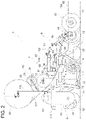
- FIG. 2 A side view of the mulching machine.
- FIG. 3 A plan view schematically illustrating main parts of the mulching machine.
- FIG. 4 A view illustrating a state where the mulching machine was performing work.
- FIG. 5 A side view illustrating the mulching machine separated into a front unit and a rear unit.
- FIG. 6 A view illustrating a portion for coupling the front unit and the rear unit to each other.
- FIG. 7 A view for explaining positional arrangement of the main parts of the mulching machine, viewed from a side.
- FIG. 8 A perspective view of a braking unit.
- a mulching machine 1 is configured to be attachable to a rear portion of a tractor 2 .
- the rear portion of the tractor 2 has a three-link mechanism including right and left paired lower links 3 and an upper link 4 .
- the mulching machine 1 is configured to be attachable to the three-link mechanism.
- the rear portion of the tractor 2 has a lifting device (not illustrated) including a hydraulic device such as a lifting cylinder. As a result of lifting or lowering of the three-link mechanism, the mulching machine 1 is lifted or lowered.
- the mulching machine 1 has a machine body 5 including a tilling unit 6 for performing tilling, a ridge forming unit 7 for forming, with use of the tilled soil, a ridge 10 having a trapezoid cross section, a mulch film laying unit 8 for drawing a mulch film 82 from a film roll 81 and laying the mulch film 82 over the ridge 10 , and ground wheels 9 that can support the machine body 5 .
- the tilling unit 6 includes a tilling shaft 61 configured to be rotated by rotational drive power transmitted from a power take-off (PTO) shaft (not illustrated) provided in the rear portion of the tractor 2 (see FIG. 1 ) and a plurality of tilling claws 62 configured to perform tilling along with the rotation of the tilling shaft 61 .
- the tilling shaft 61 and the tilling claws 62 are disposed across the full length of the machine body 5 of the mulching machine 1 in a width direction of the machine body 5 (i.e., in a width direction of the tractor 2 ).
- a power transmission unit and/or the like (not illustrated) for transmitting the rotational drive power from the PTO shaft to the tilling shaft 61 is accommodated in a transmission case 63 .
- the tilling unit 6 includes a cover 74 (see FIG. 6 ) that covers the upper and rear sides of the tilling claws 62 .
- the ridge forming unit 7 is provided in a laterally center portion (i.e., a center portion in the width direction) of the machine body 5 of the mulching machine 1 .
- the ridge forming unit 7 includes an upper-side forming plate 71 for forming the upper side of a ridge and right and left paired lateral-side forming plates 72 for forming the lateral sides of the ridge.
- FIG. 3 is a plan view schematically illustrating positional arrangement of the elements in the mulching machine 1 , such as the ridge forming unit 7 , the ground wheels 9 , the film roll 81 , and a tube roll 90 .
- the upper-side forming plate 71 is shaped in a plate extending in a traveling direction of the machine body 5 and being inclined downward as it gets closer to the rear side of the machine body 5 in the traveling direction of the machine body 5 (i.e., as it gets closer to the lower side in FIG. 3 and the right side in FIG. 7 ).
- Each of the lateral-side forming plates 72 is shaped in a plate extending in a top-bottom direction and being inclined laterally outward of the machine body 5 (i.e., outward in the width direction of the machine body 5 ; rightward or leftward in FIG. 3 ) as it gets closer to the bottom.
- the ridge forming unit 7 includes, in its front portion, soil moving plates 73 for moving, toward the ridge forming unit 7 , the soil tilled by the tilling unit 6 .
- Each of the soil moving plates 73 is shaped in a plate extending from the front end of a respective one of the right and left paired lateral-side forming plates 72 toward the front side in the traveling direction of the machine body 5 .
- each of the soil moving plates 73 is inclined outward as it gets closer to the front side in the traveling direction of the machine body 5 .
- the mulch film laying unit 8 includes the film roll 81 around which the mulch film 82 is wound, a first intermediate guide roller 83 and a second intermediate guide roller 84 for guiding the mulch film 82 drawn from the film roll 81 , a laying roller 85 for laying a laterally center portion of the mulch film 82 (i.e., a center portion of the mulch film 82 in the width direction of the mulch film 82 ) on the upper side 10 a of the ridge 10 , right and left paired trampling wheels 86 for trampling the laterally opposite ends of the mulch film 82 (i.e., the ends of the mulch film 82 in the width direction of the mulch film 82 ) to lay the mulch film 82 on the laterally opposite sides of the ridge 10 , and right and left paired soil covering wheels 87 for covering, with the soil, the laterally opposite ends of the mulch film 82 having been laid by the trampling wheels 86 .
- the first intermediate guide roller 83 and the second intermediate guide roller 84 are disposed across the full length of the mulch film 82 in a width direction of the mulch film 82 .
- the first intermediate guide roller 83 and the second intermediate guide roller 84 are configured to guide, toward the upper side 10 a of the ridge 10 formed by the ridge forming unit 7 , the mulch film 82 drawn from the film roll 81 .
- a lifting support 88 is provided between the film roll 81 and the first intermediate guide roller 83 .
- the lifting support 88 is configured to lift upward the mulch film 82 drawn from the film roll 81 and to support the mulch film 82 at that position.
- the mulch film 82 is arranged such that the mulch film 82 is guided by the lifting support 88 , the first intermediate guide roller 83 , and the second intermediate guide roller 84 with a tension applied to the mulch film 82 .
- the laying roller 85 is disposed across the full length of the upper side 10 a of the ridge 10 in the width direction of the upper side 10 a , and is configured to press the mulch film 82 downward so that the mulch film 82 is laid on the upper side 10 a of the ridge 10 .
- FIG. 4 shows an image of the mulching machine 1 taken from an obliquely rear side while the mulching machine 1 was performing the work of laying the mulch film 82 and a watering tube 91 .
- the trampling wheels 86 trample on the mulch film 82 to draw the mulch film 82 from the film roll 81 .
- the mulch film 82 is laid on the laterally opposite sides of the ridge 10 .
- the soil covering wheels 87 are positioned at locations overlapping the trampling wheels 86 in the traveling direction of the machine body 5 . As the machine body 5 travels, the soil covering wheels 87 cover, with the soil, the laterally opposite ends of the mulch film 82 laid on the laterally opposite sides of the ridge 10 . Thanks to this, the ridge 10 is kept covered with the mulch film 82 .
- the mulch film laying unit 8 which can lay the mulch film 82 over the ridge 10 , is also configured to be capable of laying the mulch film 82 over the ridge 10 while drawing the watering tube 91 from the tube roll 90 and laying the watering tube 91 on the upper side 10 a of the ridge 10 .
- the mulch film laying unit 8 includes the film roll 81 around which the mulch film 82 is wound and the tube roll 90 around which the watering tube 91 is wound. As the machine body 5 travels, the mulch film laying unit 8 draws the watering tube 91 from the tube roll 90 and guides the watering tube 91 to be placed under the mulch film 82 .
- the laying roller 85 lays the watering tube 91 and the mulch film 82 on the upper side 10 a of the ridge 10 . Consequently, the mulch film 82 is laid over the ridge 10 with the watering tube 91 laid on the upper side 10 a of the ridge 10 .
- the machine body 5 of the mulching machine 1 can be separated into a front unit 11 including the tilling unit 6 and a rear unit 12 including the ground wheels 9 and the ridge forming unit 7 .
- the front unit 11 has a rear end whose laterally opposite ends are respectively provided with front couplers 13 , via which the front unit 11 is coupled to the rear unit 12 .
- the rear unit 12 has a front end whose laterally opposite ends are respectively provided with rear couplers 14 , via which the rear unit 12 is coupled to the front unit 11 .
- Each of the front couplers 13 is shaped in a plate extending in the top-bottom direction and having a recessed slit 15 opened upward.
- Each of the rear couplers 14 includes two plate-shaped members spaced from each other in the width direction of the machine body 5 and a bar-shaped member 16 laid between the two plate-shaped members. The two plate-shaped members of each of the rear couplers 14 are fitted into a respective one of the front couplers 13 so that the bar-shaped member 16 is engaged with the slit 15 . Then, the front coupler 13 and the rear coupler 14 are fixed to each other via a fastener and/or the like (not illustrated). In this manner, the front unit 11 and the rear unit 12 can be coupled to each other.
- the front unit 11 includes a first lateral machine frame 101 extending in the width direction of the machine body 5 , right and left paired first support frames 111 extending from a portion above the tilling unit 6 to a portion above the ridge forming unit 7 along the traveling direction of the machine body 5 (front-rear direction), right and left paired second support frames 112 extending upward from the right and left paired first support frames 111 , respectively, and right and left paired third support frames 113 extending in the top-bottom direction.
- the first lateral machine frame 101 is laid across the full length of the tilling unit 6 in the width direction of the machine body 5 .
- the first lateral machine frame 101 supports the tilling unit 6 , including the transmission case 63 , a cover 74 (see FIG. 6 ) covering the tilling claws 62 , and the like.
- the first support frames 111 are positioned at locations respectively corresponding to the laterally opposite ends of the machine body 5 (i.e., the opposite ends of the machine body 5 in the width direction of the machine body 5 ).
- the first support frames 111 extend rearward from the cover 74 (see FIG. 6 ) covering the tilling claws 62 and the like.
- the second support frames 112 extend upward from rear portions of the respective first support frames 111 .
- the film roll 81 is supported by the right and left paired second support frames 112 with the film roll 81 laid between the second support frames 112 .
- the third support frames 113 are located at a laterally center portion of the machine body 5 (i.e., a center portion of the machine body 5 in the width direction of the machine body 5 ), and extend upward from the cover 74 (see FIG. 6 ) covering the tilling claws 62 and the like.
- the tube roll 90 is supported by the right and left paired third support frames 113 with the tube roll 90 laid between the third support frames 113 .
- the tube roll 90 and the film roll 81 are included in the front unit 11 in a state where the tube roll 90 and the film roll 81 are supported by the front unit 11 .
- the rear unit 12 includes a second lateral machine frame 102 extending in the width direction of the machine body 5 and a third lateral machine frame 103 extending in the width direction of the machine body 5 .
- the third lateral machine frame 103 is positioned at a location rearward and upward of the second lateral machine frame 102 .
- the second lateral machine frame 102 and the third lateral machine frame 103 are connected to each other via couplers 120 extending in the traveling direction (front-rear direction) of the machine body 5 .
- the couplers 120 are positioned at locations respectively corresponding to the laterally opposite ends of the machine body 5 .
- the couplers 120 are configured to connect the laterally opposite ends of the second lateral machine frame 102 to the laterally opposite ends of the third lateral machine frame 103 , respectively.
- the laterally opposite ends of the second lateral machine frame 102 are respectively connected to fourth support frames 114 extending downward.
- the fourth support frames 114 support the lateral-side forming plates 72 of the ridge forming unit 7 and the ground wheels 9 .
- the upper-side forming plate 71 of the ridge forming unit 7 and the first intermediate guide roller 83 are supported by a support frame connected to the second lateral machine frame 102 .
- the laterally opposite ends of the second lateral machine frame 102 are respectively coupled to fifth support frames 115 extending rearward.
- the fifth support frames 115 support the trampling wheels 86 and the soil covering wheels 87 .
- Each of the fifth support frames 115 is constituted by support frames coupled to each other.
- each of the fifth support frames 115 one of the support frames supporting a corresponding one of the trampling wheels 86 and a corresponding one of the soil covering wheels 87 is pivotally linked to another one of the support frames in such a manner that the one of the support frames is movable in a swinging motion.
- the support frames supporting the trampling wheels 86 and the soil covering wheels 87 are moved upward in a swinging motion, so that the trampling wheels 86 and the soil covering wheels 87 can be moved upward to a retracted position upwardly away from the field.
- the third lateral machine frame 103 has, in its center, a sixth support frame 116 extending rearward to a midway portion and extending downward therefrom.
- the sixth support frame 116 supports the second intermediate guide roller 84 and the laying roller 85 .
- the tilling unit 6 and the ridge forming unit 7 are arranged in this order from the front side (the left side in FIG. 7 ) in the traveling direction of the machine body 5 .
- the ground wheels 9 are arranged laterally to the right and left sides of the ridge forming unit 7 , as illustrated in FIG. 3 .
- the ground wheels 9 are positioned rearward of the tilling unit 6 , as illustrated in FIG. 7 .
- the film roll 81 is positioned such that, as illustrated in FIGS. 3 and 7 , the center of gravity G 1 of the film roll 81 does not overlap the ground wheels 9 and is located forward of the ground wheels 9 in the traveling direction of the machine body 5 and forward of the ridge forming unit 7 in the traveling direction of the machine body 5 .
- the film roll 81 is arranged such that, as illustrated in FIG. 7 , the center of gravity G 1 of the film roll 81 is located between the tilling unit 6 and the ridge forming unit 7 in the traveling direction of the machine body 5 , and the film roll 81 is located upward of the tilling unit 6 and the ridge forming unit 7 .
- a space between the center of the tilling shaft 61 of the tilling unit 6 and the center of one of the ground wheels 9 is evenly divided into three regions, i.e., a front part P 1 , an intermediate part P 2 , and a rear part P 3 .
- the film roll 81 is arranged such that the center of gravity G 1 of the film roll 81 is positioned in the front part P 1 or the intermediate part P 2 , each of which is located forward of the rear part P 3 .
- the film roll 81 positioned at the above-described location hardly causes an increase in the load applied to a portion of the mulching machine 1 which portion is rearward of the ground wheels 9 .
- the machine body 5 of the mulching machine 1 can be supported by the ground wheels 9 in a suitable manner.
- the power transmission unit and/or the like for transmitting rotational drive power from the PTO shaft is a heavy article, and therefore the center of gravity of the mulching machine 1 is located at or near the tilling unit 6 .
- the center of gravity of the film roll 81 can be located closer to the tilling unit 6 when viewed in the traveling direction of the machine body 5 . Accordingly, even if the weight of the film roll 81 is increased due to an increase in the number of turns of the film roll 81 , a suitable weight balance in the traveling direction of the machine body 5 can be maintained.
- the tube roll 90 is positioned at the center in the width direction of the machine body 5 .
- the tube roll 90 is positioned at a location overlapping the tilling unit 6 in the traveling direction of the machine body 5 and being away from and upward of the tilling unit 6 . This creates a space between the tube roll 90 and the tilling unit 6 .
- the film roll 81 is positioned to enter a space under the tube roll 90 .
- both of the tube roll 90 and the film roll 81 can be arranged efficiently in a settled manner while the centers of gravity of the tube roll 90 and the film roll 81 are located closer to the tilling unit 6 . Consequently, even if the weight of the tube roll 90 is added as a result of attachment of the tube roll 90 and the weight of the film roll 81 is increased due to an increase in the number of turns of the film roll 81 , it is possible to maintain a suitable weight balance in the traveling direction of the machine body 5 .
- the mulching machine 1 includes a braking unit 20 configured to come in contact with the outer periphery of the film roll 81 to give braking power to the film roll 81 .
- FIG. 8 is a perspective view of main parts of the braking unit 20 , viewed from the right side of the mulching machine 1 .
- the braking unit 20 is positioned on the right side of the tube roll 90 in the width direction of the machine body 5 . Namely, the braking unit 20 is positioned at a location laterally away from the tube roll 90 , which is positioned at the center.
- the braking unit 20 includes a roller 21 that is rotatable while being in contact with the outer periphery of the film roll 81 and braking power giving members 22 configured to come in contact with the side surfaces of the roller 21 , respectively, to give braking power to the roller 21 .
- the machine body 5 includes a seventh support frame 117 extending obliquely rearward from a position above the tilling unit 6 .
- a roller 21 is supported rotatably. The roller 21 is disposed above the film roll 81 such that the roller 21 comes in contact with an upper portion of the outer periphery of the film roll 81 .
- the proximal end (front end) of the seventh support frame 117 is coupled to a portion of the machine body 5 which portion is rearward of the first support frame 111 .
- the proximal end of the seventh support frame 117 is rotatable around an axis being in parallel to the width direction of the machine body 5 .
- a spring 25 is interposed between the seventh support frame 117 and the coupled portion, so that the spring 25 gives a biasing force for causing the seventh support frame 117 to move downward in a swinging motion.
- the biasing force given by the spring 25 acts to press the roller 21 onto the outer periphery of the film roll 81 .
- the distal end of the seventh support frame 117 is provided with a handle 24 extending therefrom.
- An operator or the like can hold the handle 24 to cause the seventh support frame 117 to move forward and upward in a swinging motion. This releases the contact between the roller 21 and the outer periphery of the film roll 81 , so that the roller 21 can be moved to a position away from the film roll 81 .
- the braking power giving members 22 are each shaped in a disc configured to come in contact with a corresponding one of the side surfaces of the roller 21 .
- the right and left paired braking power giving members 22 are arranged such that the roller 21 is sandwiched therebetween.
- a compression spring is provided between the braking power giving members 22 and a spring washer. With this configuration, a fastening force is given to the right and left paired braking power giving members 22 so that the right and left paired braking power giving members 22 are pressed onto the side surfaces of the roller 21 , respectively.
- the roller 21 has an elastic member 23 that is a contact portion configured to come in contact with the outer periphery of the film roll 81 .
- the elastic member 23 is a sponge or rubber member having a tubular shape and being outwardly fitted to the outer periphery of the roller 21 .
- the film roll 81 may be positioned at any location, as long as the film roll 81 is positioned such that the center of gravity G 1 of the film roll 81 does not overlap the ground wheels 9 and is located forward of the ground wheels 9 in the traveling direction of the machine body 5 , and is located forward of the ridge forming unit 7 in the traveling direction of the machine body 5 .
- a distance by which the center of gravity G 1 of the film roll 81 is forward of the ground wheels 9 can be changed as appropriate.
- a distance by which the center of gravity G 1 of the film roll 81 is forward of the ridge forming unit 7 can be changed as appropriate.
- the film roll 81 may be positioned such that the center of gravity G 1 of the film roll 81 overlaps the tilling unit 6 .
- the mulch film laying unit 8 is configured to lay not only the mulch film 82 but also the watering tube 91 over the ridge 10 .
- the tube roll 90 may be omitted, and the mulch film laying unit 8 may be configured to lay only the mulch film 82 over the ridge 10 .
- the film roll 81 may be positioned at a location overlapping the tilling unit 6 in the traveling direction of the machine body 5 , for example.
- the machine body 5 of the mulching machine 1 can be separated into the front unit 11 and the rear unit 12 .
- the machine body 5 of the mulching machine 1 may not be separated into the front unit 11 and the rear unit 12 , but may have an integrated configuration.
- the mulching machine 1 includes the braking unit 20 configured to come in contact with the outer periphery of the film roll 81 to give braking power to the film roll 81 .
- the configuration of the braking unit is not limitative. The braking unit only needs to be capable of giving braking power to the film roll 81 .
- the embodiment described above has dealt with the example in which the mulching machine 1 is attached to the rear portion of the tractor 2 in such a manner that the mulching machine 1 can be lifted and lowered.
- the mulching machine 1 may be attached to a rear portion of another type of trailing vehicle.
- the vehicle towing the mulching machine 1 is not limited to the tractor 2 .
- the present invention is applicable to a mulching machine for forming a ridge as a machine body of the mulching machine travels and for laying a mulch film over the ridge.
Landscapes
- Life Sciences & Earth Sciences (AREA)
- Environmental Sciences (AREA)
- Engineering & Computer Science (AREA)
- Mechanical Engineering (AREA)
- Soil Sciences (AREA)
- Health & Medical Sciences (AREA)
- General Health & Medical Sciences (AREA)
- Toxicology (AREA)
- Protection Of Plants (AREA)
- Soil Working Implements (AREA)
Abstract
Description
-
- a tilling unit for performing tilling,
- a ridge forming unit for forming a ridge with use of the tilled soil,
- a mulch film laying unit for drawing a mulch film from a film roll and laying the mulch film over the ridge, and
- ground wheels capable of supporting the machine body, wherein
-
- a roller that is rotatable while being in contact with the outer periphery of the film roll and
- braking power giving members configured to come in contact with side surfaces of the roller, respectively, to give braking power to the roller, and
Claims (12)
Applications Claiming Priority (4)
| Application Number | Priority Date | Filing Date | Title |
|---|---|---|---|
| JP2017005369A JP6877151B2 (en) | 2017-01-16 | 2017-01-16 | Multi-working machine |
| JP2017-005369 | 2017-01-16 | ||
| JPJP2017-005369 | 2017-01-16 | ||
| PCT/JP2018/000766 WO2018131701A1 (en) | 2017-01-16 | 2018-01-15 | Multitask machine |
Publications (2)
| Publication Number | Publication Date |
|---|---|
| US20190364716A1 US20190364716A1 (en) | 2019-12-05 |
| US11297752B2 true US11297752B2 (en) | 2022-04-12 |
Family
ID=62839887
Family Applications (1)
| Application Number | Title | Priority Date | Filing Date |
|---|---|---|---|
| US16/478,039 Active 2038-09-26 US11297752B2 (en) | 2017-01-16 | 2018-01-15 | Mulching machine |
Country Status (4)
| Country | Link |
|---|---|
| US (1) | US11297752B2 (en) |
| EP (1) | EP3569059A4 (en) |
| JP (1) | JP6877151B2 (en) |
| WO (1) | WO2018131701A1 (en) |
Families Citing this family (11)
| Publication number | Priority date | Publication date | Assignee | Title |
|---|---|---|---|---|
| CN109673186B (en) * | 2019-01-22 | 2021-10-08 | 江苏大学 | A small-scale agricultural rotary tillage, ridge-raising and film-covering integrated machine |
| CN110810095A (en) * | 2019-11-06 | 2020-02-21 | 肖建堤 | A device for laying mulch film for crop cultivation |
| CN111418288B (en) * | 2020-04-21 | 2022-06-21 | 吉林省农业科学院 | Industrial hemp tectorial membrane suppression all-in-one |
| CN111869484A (en) * | 2020-07-20 | 2020-11-03 | 胡鑫 | Garlic is planted and buries native all-in-one with tectorial membrane |
| CN112088590B (en) * | 2020-10-13 | 2025-06-20 | 陇西县渭河福利机械制造有限责任公司 | Ridge spraying and film covering machine |
| CN112314076A (en) * | 2020-11-11 | 2021-02-05 | 山东省农业机械科学研究院 | A rotary tiller for planting crops in hilly areas |
| CN112292941A (en) * | 2020-11-18 | 2021-02-02 | 艾海提·阿卜力米提 | Cotton stalk crushing and returning combined machine for recovering residual film |
| CN114303487A (en) * | 2021-12-30 | 2022-04-12 | 广西壮族自治区亚热带作物研究所(广西亚热带农产品加工研究所) | A papaya planter |
| CN114616939A (en) * | 2022-01-29 | 2022-06-14 | 常州汉森机械股份有限公司 | Farmland plastic film recycling machine |
| CN114521350B (en) * | 2022-02-25 | 2022-11-22 | 连云港九迁机械制造有限公司 | Big data-based rotary cultivator with strong soil condition self-adaption capability |
| CN114342624B (en) * | 2022-02-25 | 2022-09-27 | 广州大学 | Automatic irrigation and fertilization all-in-one is planted to sugarcane intelligence |
Citations (33)
| Publication number | Priority date | Publication date | Assignee | Title |
|---|---|---|---|---|
| US2740233A (en) * | 1954-04-22 | 1956-04-03 | Reynolds Metals Co | Machine for foil protection of plant growth |
| US2890665A (en) * | 1956-01-30 | 1959-06-16 | Lawrence S C Kang | Planting machine |
| US3121973A (en) | 1962-01-05 | 1964-02-25 | Soilserv Inc | Soil treating method |
| US3180290A (en) * | 1962-08-13 | 1965-04-27 | Prec Agricultural Machinery Co | Plastic sheet laying and planting machine |
| US3204589A (en) * | 1962-06-27 | 1965-09-07 | Homer T Blackhurst | Mulching and seeding apparatus |
| US3293797A (en) * | 1965-04-01 | 1966-12-27 | Prec Agricultural Machinery Co | Sheet laying method and apparatus |
| US3468267A (en) * | 1966-08-02 | 1969-09-23 | Union Carbide Corp | Mulching and seeding apparatus |
| US3559599A (en) * | 1968-12-06 | 1971-02-02 | Campbell Soup Co | Machine for planting and sealing furrow with transparent material |
| US3751821A (en) * | 1971-12-13 | 1973-08-14 | Univ California | Raisin grape spreader |
| US4117787A (en) * | 1976-09-20 | 1978-10-03 | Pavan Jean Paul | Machine for performing cultivation under plastics |
| US4285161A (en) * | 1979-04-03 | 1981-08-25 | Kubota Ltd. | Mulcher |
| JPS5737950Y2 (en) | 1978-12-07 | 1982-08-20 | ||
| US4377979A (en) * | 1981-03-31 | 1983-03-29 | Hiniker Company | Conservation tillage row crop planter system |
| US4513530A (en) * | 1983-06-22 | 1985-04-30 | Mechanical Transplanter Company | Machine for laying film material |
| US4886002A (en) * | 1986-11-06 | 1989-12-12 | Loris Scudellaro | Transplanting machine |
| US4953482A (en) * | 1984-07-18 | 1990-09-04 | Atochem | Mulching and seeding apparatus and method with film severing and covering |
| JPH0516888Y2 (en) | 1987-10-05 | 1993-05-07 | ||
| US5226376A (en) * | 1991-10-25 | 1993-07-13 | Ellsworth Shaw | Machine for laying agricultural plastic film |
| US5906167A (en) * | 1995-07-06 | 1999-05-25 | Sanyo Turf Co., Ltd. | Method and apparatus for planting net tape runners |
| JP2004065024A (en) | 2002-08-01 | 2004-03-04 | Kubota Corp | Ground work machine |
| JP3642902B2 (en) | 1996-10-16 | 2005-04-27 | 石川島芝浦機械株式会社 | Multi film coating equipment |
| US20050198895A1 (en) * | 2004-03-15 | 2005-09-15 | Rose Mark D. | Machine for laying ground cover on seeded areas |
| JP3727618B2 (en) | 2002-08-06 | 2005-12-14 | 鋤柄農機株式会社 | Spare film roll support structure for multi-work machine |
| JP2009106189A (en) | 2007-10-30 | 2009-05-21 | Sano Atatsuchi Kenkyusho:Kk | Mulching sheet-laying machine with feeding-out device |
| JP2009225706A (en) | 2008-03-21 | 2009-10-08 | Sukigara Noki Kk | Mulching working machine |
| JP2009291125A (en) | 2008-06-05 | 2009-12-17 | Mitsubishi Agricult Mach Co Ltd | Operating machine for laying mulching sheet |
| US20110209885A1 (en) * | 2007-12-17 | 2011-09-01 | Rocca Manufacturing Pty Ltd | Plastic mulch retrievers |
| US20190166753A1 (en) * | 2012-02-03 | 2019-06-06 | Tillage Management Incorporated | Reconfigurable tillage system |
| US10433494B1 (en) * | 2016-08-08 | 2019-10-08 | Edward E. Woerner | Steam treatment of soil |
| US20190364747A1 (en) * | 2017-02-14 | 2019-12-05 | Norseman Machinery Imports Pty Ltd | Improved film deployer, improved trash whipper and improved planter |
| US10512222B1 (en) * | 2016-08-08 | 2019-12-24 | Edward E. Woerner | Steam treatment of soil |
| US20200236873A1 (en) * | 2019-01-24 | 2020-07-30 | Willie L. Albrecht | Apparatus, Systems and Methods for Dispensing and Laying a Sheet of Film Material |
| US20200390019A1 (en) * | 2019-06-13 | 2020-12-17 | Nanjing Institute Of Agricultural Mechanization, Ministry Of Agriculture And Rural Affairs | Fully-automatic transplanting combined machine |
Family Cites Families (2)
| Publication number | Priority date | Publication date | Assignee | Title |
|---|---|---|---|---|
| JPS6010683B2 (en) * | 1981-12-15 | 1985-03-19 | 茂三 平塚 | folding multilayer |
| JP3862364B2 (en) * | 1997-05-30 | 2006-12-27 | 鋤柄農機株式会社 | Multi working machine |
-
2017
- 2017-01-16 JP JP2017005369A patent/JP6877151B2/en active Active
-
2018
- 2018-01-15 WO PCT/JP2018/000766 patent/WO2018131701A1/en not_active Ceased
- 2018-01-15 EP EP18738941.6A patent/EP3569059A4/en not_active Withdrawn
- 2018-01-15 US US16/478,039 patent/US11297752B2/en active Active
Patent Citations (33)
| Publication number | Priority date | Publication date | Assignee | Title |
|---|---|---|---|---|
| US2740233A (en) * | 1954-04-22 | 1956-04-03 | Reynolds Metals Co | Machine for foil protection of plant growth |
| US2890665A (en) * | 1956-01-30 | 1959-06-16 | Lawrence S C Kang | Planting machine |
| US3121973A (en) | 1962-01-05 | 1964-02-25 | Soilserv Inc | Soil treating method |
| US3204589A (en) * | 1962-06-27 | 1965-09-07 | Homer T Blackhurst | Mulching and seeding apparatus |
| US3180290A (en) * | 1962-08-13 | 1965-04-27 | Prec Agricultural Machinery Co | Plastic sheet laying and planting machine |
| US3293797A (en) * | 1965-04-01 | 1966-12-27 | Prec Agricultural Machinery Co | Sheet laying method and apparatus |
| US3468267A (en) * | 1966-08-02 | 1969-09-23 | Union Carbide Corp | Mulching and seeding apparatus |
| US3559599A (en) * | 1968-12-06 | 1971-02-02 | Campbell Soup Co | Machine for planting and sealing furrow with transparent material |
| US3751821A (en) * | 1971-12-13 | 1973-08-14 | Univ California | Raisin grape spreader |
| US4117787A (en) * | 1976-09-20 | 1978-10-03 | Pavan Jean Paul | Machine for performing cultivation under plastics |
| JPS5737950Y2 (en) | 1978-12-07 | 1982-08-20 | ||
| US4285161A (en) * | 1979-04-03 | 1981-08-25 | Kubota Ltd. | Mulcher |
| US4377979A (en) * | 1981-03-31 | 1983-03-29 | Hiniker Company | Conservation tillage row crop planter system |
| US4513530A (en) * | 1983-06-22 | 1985-04-30 | Mechanical Transplanter Company | Machine for laying film material |
| US4953482A (en) * | 1984-07-18 | 1990-09-04 | Atochem | Mulching and seeding apparatus and method with film severing and covering |
| US4886002A (en) * | 1986-11-06 | 1989-12-12 | Loris Scudellaro | Transplanting machine |
| JPH0516888Y2 (en) | 1987-10-05 | 1993-05-07 | ||
| US5226376A (en) * | 1991-10-25 | 1993-07-13 | Ellsworth Shaw | Machine for laying agricultural plastic film |
| US5906167A (en) * | 1995-07-06 | 1999-05-25 | Sanyo Turf Co., Ltd. | Method and apparatus for planting net tape runners |
| JP3642902B2 (en) | 1996-10-16 | 2005-04-27 | 石川島芝浦機械株式会社 | Multi film coating equipment |
| JP2004065024A (en) | 2002-08-01 | 2004-03-04 | Kubota Corp | Ground work machine |
| JP3727618B2 (en) | 2002-08-06 | 2005-12-14 | 鋤柄農機株式会社 | Spare film roll support structure for multi-work machine |
| US20050198895A1 (en) * | 2004-03-15 | 2005-09-15 | Rose Mark D. | Machine for laying ground cover on seeded areas |
| JP2009106189A (en) | 2007-10-30 | 2009-05-21 | Sano Atatsuchi Kenkyusho:Kk | Mulching sheet-laying machine with feeding-out device |
| US20110209885A1 (en) * | 2007-12-17 | 2011-09-01 | Rocca Manufacturing Pty Ltd | Plastic mulch retrievers |
| JP2009225706A (en) | 2008-03-21 | 2009-10-08 | Sukigara Noki Kk | Mulching working machine |
| JP2009291125A (en) | 2008-06-05 | 2009-12-17 | Mitsubishi Agricult Mach Co Ltd | Operating machine for laying mulching sheet |
| US20190166753A1 (en) * | 2012-02-03 | 2019-06-06 | Tillage Management Incorporated | Reconfigurable tillage system |
| US10433494B1 (en) * | 2016-08-08 | 2019-10-08 | Edward E. Woerner | Steam treatment of soil |
| US10512222B1 (en) * | 2016-08-08 | 2019-12-24 | Edward E. Woerner | Steam treatment of soil |
| US20190364747A1 (en) * | 2017-02-14 | 2019-12-05 | Norseman Machinery Imports Pty Ltd | Improved film deployer, improved trash whipper and improved planter |
| US20200236873A1 (en) * | 2019-01-24 | 2020-07-30 | Willie L. Albrecht | Apparatus, Systems and Methods for Dispensing and Laying a Sheet of Film Material |
| US20200390019A1 (en) * | 2019-06-13 | 2020-12-17 | Nanjing Institute Of Agricultural Mechanization, Ministry Of Agriculture And Rural Affairs | Fully-automatic transplanting combined machine |
Non-Patent Citations (1)
| Title |
|---|
| International Search Report dated Apr. 17, 2018 issued in corresponding PCT Application PCT/JP2018/000766cites the patent documents above. |
Also Published As
| Publication number | Publication date |
|---|---|
| US20190364716A1 (en) | 2019-12-05 |
| WO2018131701A1 (en) | 2018-07-19 |
| EP3569059A4 (en) | 2020-11-18 |
| JP2018113871A (en) | 2018-07-26 |
| EP3569059A1 (en) | 2019-11-20 |
| JP6877151B2 (en) | 2021-05-26 |
Similar Documents
| Publication | Publication Date | Title |
|---|---|---|
| US11297752B2 (en) | Mulching machine | |
| US11617297B2 (en) | Agricultural vehicle-trailer combination | |
| ES2658053T3 (en) | Collection head without external frame | |
| US8739650B2 (en) | Control lever device for work vehicle | |
| JP2000300035A (en) | Mowing machine having cutting apparatus linked to chassis via improved linking device | |
| JP2023126618A (en) | mower | |
| KR200483458Y1 (en) | Caterpillar and caterpillar capable of selectively varying the position of manure | |
| US8555606B2 (en) | Agricultural machine movable between a lateral transport position and an operative position | |
| JP6785688B2 (en) | Work vehicle | |
| JP6089724B2 (en) | Chemical spray vehicle | |
| JP2014030363A (en) | Ground leveling member for agricultural working machine | |
| JP4110321B2 (en) | Agricultural work equipment mounting device | |
| JPS606382Y2 (en) | Power work vehicle with simple riding device | |
| JPH0143987Y2 (en) | ||
| JP2014144665A5 (en) | ||
| JPH05294253A (en) | Self-traveling working vehicle | |
| US20160135355A1 (en) | Implement and work vehicle | |
| ITMI992349A1 (en) | CUTTING EQUIPMENT WITH WHEEL AND SIMILAR BLADES APPLIED TO THE FRONT OF A DRIVE | |
| JP2733808B2 (en) | Pull-out transport mechanism for agricultural harvesting equipment | |
| JP2004182020A (en) | Farm work vehicle | |
| JP6191744B2 (en) | Walking type management machine | |
| JP2017055667A (en) | Agricultural work truck of high floor form | |
| JP5991170B2 (en) | Walking type work machine | |
| JPH0646274Y2 (en) | Combine harvester structure | |
| IT202300001083A1 (en) | LAWN MOWER MACHINE |
Legal Events
| Date | Code | Title | Description |
|---|---|---|---|
| AS | Assignment |
Owner name: YANMAR CO., LTD., JAPAN Free format text: ASSIGNMENT OF ASSIGNORS INTEREST;ASSIGNORS:KISHIMOTO, TAKESHI;KOTANI, KAZUYUKI;KOKUBUNJI, TOSHIKAZU;AND OTHERS;SIGNING DATES FROM 20190612 TO 20190624;REEL/FRAME:049753/0731 |
|
| FEPP | Fee payment procedure |
Free format text: ENTITY STATUS SET TO UNDISCOUNTED (ORIGINAL EVENT CODE: BIG.); ENTITY STATUS OF PATENT OWNER: LARGE ENTITY |
|
| AS | Assignment |
Owner name: YANMAR POWER TECHNOLOGY CO., LTD., JAPAN Free format text: CHANGE OF NAME;ASSIGNOR:YANMAR CO., LTD.;REEL/FRAME:053070/0206 Effective date: 20200401 |
|
| STPP | Information on status: patent application and granting procedure in general |
Free format text: NON FINAL ACTION MAILED |
|
| STPP | Information on status: patent application and granting procedure in general |
Free format text: RESPONSE TO NON-FINAL OFFICE ACTION ENTERED AND FORWARDED TO EXAMINER |
|
| STPP | Information on status: patent application and granting procedure in general |
Free format text: NOTICE OF ALLOWANCE MAILED -- APPLICATION RECEIVED IN OFFICE OF PUBLICATIONS |
|
| STPP | Information on status: patent application and granting procedure in general |
Free format text: PUBLICATIONS -- ISSUE FEE PAYMENT VERIFIED |
|
| STCF | Information on status: patent grant |
Free format text: PATENTED CASE |
|
| FEPP | Fee payment procedure |
Free format text: MAINTENANCE FEE REMINDER MAILED (ORIGINAL EVENT CODE: REM.); ENTITY STATUS OF PATENT OWNER: LARGE ENTITY |