US11279357B2 - Vehicle diagnosis system and method - Google Patents
Vehicle diagnosis system and method Download PDFInfo
- Publication number
- US11279357B2 US11279357B2 US15/369,920 US201615369920A US11279357B2 US 11279357 B2 US11279357 B2 US 11279357B2 US 201615369920 A US201615369920 A US 201615369920A US 11279357 B2 US11279357 B2 US 11279357B2
- Authority
- US
- United States
- Prior art keywords
- engine
- vehicle
- stop
- value
- prerequisite
- Prior art date
- Legal status (The legal status is an assumption and is not a legal conclusion. Google has not performed a legal analysis and makes no representation as to the accuracy of the status listed.)
- Active
Links
Images


Classifications
-
- G—PHYSICS
- G07—CHECKING-DEVICES
- G07C—TIME OR ATTENDANCE REGISTERS; REGISTERING OR INDICATING THE WORKING OF MACHINES; GENERATING RANDOM NUMBERS; VOTING OR LOTTERY APPARATUS; ARRANGEMENTS, SYSTEMS OR APPARATUS FOR CHECKING NOT PROVIDED FOR ELSEWHERE
- G07C5/00—Registering or indicating the working of vehicles
- G07C5/08—Registering or indicating performance data other than driving, working, idle, or waiting time, with or without registering driving, working, idle or waiting time
- G07C5/0816—Indicating performance data, e.g. occurrence of a malfunction
- G07C5/0825—Indicating performance data, e.g. occurrence of a malfunction using optical means
-
- B—PERFORMING OPERATIONS; TRANSPORTING
- B60—VEHICLES IN GENERAL
- B60W—CONJOINT CONTROL OF VEHICLE SUB-UNITS OF DIFFERENT TYPE OR DIFFERENT FUNCTION; CONTROL SYSTEMS SPECIALLY ADAPTED FOR HYBRID VEHICLES; ROAD VEHICLE DRIVE CONTROL SYSTEMS FOR PURPOSES NOT RELATED TO THE CONTROL OF A PARTICULAR SUB-UNIT
- B60W30/00—Purposes of road vehicle drive control systems not related to the control of a particular sub-unit, e.g. of systems using conjoint control of vehicle sub-units
- B60W30/18—Propelling the vehicle
- B60W30/18009—Propelling the vehicle related to particular drive situations
- B60W30/18018—Start-stop drive, e.g. in a traffic jam
-
- B—PERFORMING OPERATIONS; TRANSPORTING
- B60—VEHICLES IN GENERAL
- B60L—PROPULSION OF ELECTRICALLY-PROPELLED VEHICLES; SUPPLYING ELECTRIC POWER FOR AUXILIARY EQUIPMENT OF ELECTRICALLY-PROPELLED VEHICLES; ELECTRODYNAMIC BRAKE SYSTEMS FOR VEHICLES IN GENERAL; MAGNETIC SUSPENSION OR LEVITATION FOR VEHICLES; MONITORING OPERATING VARIABLES OF ELECTRICALLY-PROPELLED VEHICLES; ELECTRIC SAFETY DEVICES FOR ELECTRICALLY-PROPELLED VEHICLES
- B60L15/00—Methods, circuits, or devices for controlling the traction-motor speed of electrically-propelled vehicles
- B60L15/20—Methods, circuits, or devices for controlling the traction-motor speed of electrically-propelled vehicles for control of the vehicle or its driving motor to achieve a desired performance, e.g. speed, torque, programmed variation of speed
- B60L15/2009—Methods, circuits, or devices for controlling the traction-motor speed of electrically-propelled vehicles for control of the vehicle or its driving motor to achieve a desired performance, e.g. speed, torque, programmed variation of speed for braking
-
- B—PERFORMING OPERATIONS; TRANSPORTING
- B60—VEHICLES IN GENERAL
- B60R—VEHICLES, VEHICLE FITTINGS, OR VEHICLE PARTS, NOT OTHERWISE PROVIDED FOR
- B60R16/00—Electric or fluid circuits specially adapted for vehicles and not otherwise provided for; Arrangement of elements of electric or fluid circuits specially adapted for vehicles and not otherwise provided for
- B60R16/02—Electric or fluid circuits specially adapted for vehicles and not otherwise provided for; Arrangement of elements of electric or fluid circuits specially adapted for vehicles and not otherwise provided for electric constitutive elements
- B60R16/023—Electric or fluid circuits specially adapted for vehicles and not otherwise provided for; Arrangement of elements of electric or fluid circuits specially adapted for vehicles and not otherwise provided for electric constitutive elements for transmission of signals between vehicle parts or subsystems
- B60R16/0231—Circuits relating to the driving or the functioning of the vehicle
- B60R16/0236—Circuits relating to the driving or the functioning of the vehicle for economical driving
-
- B—PERFORMING OPERATIONS; TRANSPORTING
- B60—VEHICLES IN GENERAL
- B60T—VEHICLE BRAKE CONTROL SYSTEMS OR PARTS THEREOF; BRAKE CONTROL SYSTEMS OR PARTS THEREOF, IN GENERAL; ARRANGEMENT OF BRAKING ELEMENTS ON VEHICLES IN GENERAL; PORTABLE DEVICES FOR PREVENTING UNWANTED MOVEMENT OF VEHICLES; VEHICLE MODIFICATIONS TO FACILITATE COOLING OF BRAKES
- B60T17/00—Component parts, details, or accessories of power brake systems not covered by groups B60T8/00, B60T13/00 or B60T15/00, or presenting other characteristic features
- B60T17/18—Safety devices; Monitoring
- B60T17/22—Devices for monitoring or checking brake systems; Signal devices
- B60T17/221—Procedure or apparatus for checking or keeping in a correct functioning condition of brake systems
-
- B—PERFORMING OPERATIONS; TRANSPORTING
- B60—VEHICLES IN GENERAL
- B60W—CONJOINT CONTROL OF VEHICLE SUB-UNITS OF DIFFERENT TYPE OR DIFFERENT FUNCTION; CONTROL SYSTEMS SPECIALLY ADAPTED FOR HYBRID VEHICLES; ROAD VEHICLE DRIVE CONTROL SYSTEMS FOR PURPOSES NOT RELATED TO THE CONTROL OF A PARTICULAR SUB-UNIT
- B60W20/00—Control systems specially adapted for hybrid vehicles
- B60W20/50—Control strategies for responding to system failures, e.g. for fault diagnosis, failsafe operation or limp mode
-
- B—PERFORMING OPERATIONS; TRANSPORTING
- B60—VEHICLES IN GENERAL
- B60W—CONJOINT CONTROL OF VEHICLE SUB-UNITS OF DIFFERENT TYPE OR DIFFERENT FUNCTION; CONTROL SYSTEMS SPECIALLY ADAPTED FOR HYBRID VEHICLES; ROAD VEHICLE DRIVE CONTROL SYSTEMS FOR PURPOSES NOT RELATED TO THE CONTROL OF A PARTICULAR SUB-UNIT
- B60W30/00—Purposes of road vehicle drive control systems not related to the control of a particular sub-unit, e.g. of systems using conjoint control of vehicle sub-units
- B60W30/18—Propelling the vehicle
- B60W30/18009—Propelling the vehicle related to particular drive situations
- B60W30/18109—Braking
- B60W30/18127—Regenerative braking
-
- B—PERFORMING OPERATIONS; TRANSPORTING
- B60—VEHICLES IN GENERAL
- B60W—CONJOINT CONTROL OF VEHICLE SUB-UNITS OF DIFFERENT TYPE OR DIFFERENT FUNCTION; CONTROL SYSTEMS SPECIALLY ADAPTED FOR HYBRID VEHICLES; ROAD VEHICLE DRIVE CONTROL SYSTEMS FOR PURPOSES NOT RELATED TO THE CONTROL OF A PARTICULAR SUB-UNIT
- B60W30/00—Purposes of road vehicle drive control systems not related to the control of a particular sub-unit, e.g. of systems using conjoint control of vehicle sub-units
- B60W30/18—Propelling the vehicle
- B60W30/192—Mitigating problems related to power-up or power-down of the driveline, e.g. start-up of a cold engine
-
- F—MECHANICAL ENGINEERING; LIGHTING; HEATING; WEAPONS; BLASTING
- F02—COMBUSTION ENGINES; HOT-GAS OR COMBUSTION-PRODUCT ENGINE PLANTS
- F02D—CONTROLLING COMBUSTION ENGINES
- F02D41/00—Electrical control of supply of combustible mixture or its constituents
- F02D41/02—Circuit arrangements for generating control signals
- F02D41/04—Introducing corrections for particular operating conditions
- F02D41/042—Introducing corrections for particular operating conditions for stopping the engine
-
- F—MECHANICAL ENGINEERING; LIGHTING; HEATING; WEAPONS; BLASTING
- F02—COMBUSTION ENGINES; HOT-GAS OR COMBUSTION-PRODUCT ENGINE PLANTS
- F02D—CONTROLLING COMBUSTION ENGINES
- F02D41/00—Electrical control of supply of combustible mixture or its constituents
- F02D41/22—Safety or indicating devices for abnormal conditions
-
- F—MECHANICAL ENGINEERING; LIGHTING; HEATING; WEAPONS; BLASTING
- F02—COMBUSTION ENGINES; HOT-GAS OR COMBUSTION-PRODUCT ENGINE PLANTS
- F02D—CONTROLLING COMBUSTION ENGINES
- F02D41/00—Electrical control of supply of combustible mixture or its constituents
- F02D41/24—Electrical control of supply of combustible mixture or its constituents characterised by the use of digital means
- F02D41/26—Electrical control of supply of combustible mixture or its constituents characterised by the use of digital means using computer, e.g. microprocessor
-
- F—MECHANICAL ENGINEERING; LIGHTING; HEATING; WEAPONS; BLASTING
- F02—COMBUSTION ENGINES; HOT-GAS OR COMBUSTION-PRODUCT ENGINE PLANTS
- F02N—STARTING OF COMBUSTION ENGINES; STARTING AIDS FOR SUCH ENGINES, NOT OTHERWISE PROVIDED FOR
- F02N11/00—Starting of engines by means of electric motors
- F02N11/08—Circuits specially adapted for starting of engines
- F02N11/0814—Circuits specially adapted for starting of engines comprising means for controlling automatic idle-start-stop
- F02N11/0818—Conditions for starting or stopping the engine or for deactivating the idle-start-stop mode
- F02N11/0825—Conditions for starting or stopping the engine or for deactivating the idle-start-stop mode related to prevention of engine restart failure, e.g. disabling automatic stop at low battery state
-
- G—PHYSICS
- G07—CHECKING-DEVICES
- G07C—TIME OR ATTENDANCE REGISTERS; REGISTERING OR INDICATING THE WORKING OF MACHINES; GENERATING RANDOM NUMBERS; VOTING OR LOTTERY APPARATUS; ARRANGEMENTS, SYSTEMS OR APPARATUS FOR CHECKING NOT PROVIDED FOR ELSEWHERE
- G07C5/00—Registering or indicating the working of vehicles
- G07C5/004—Indicating the operating range of the engine
-
- G—PHYSICS
- G07—CHECKING-DEVICES
- G07C—TIME OR ATTENDANCE REGISTERS; REGISTERING OR INDICATING THE WORKING OF MACHINES; GENERATING RANDOM NUMBERS; VOTING OR LOTTERY APPARATUS; ARRANGEMENTS, SYSTEMS OR APPARATUS FOR CHECKING NOT PROVIDED FOR ELSEWHERE
- G07C5/00—Registering or indicating the working of vehicles
- G07C5/08—Registering or indicating performance data other than driving, working, idle, or waiting time, with or without registering driving, working, idle or waiting time
- G07C5/0808—Diagnosing performance data
-
- G—PHYSICS
- G07—CHECKING-DEVICES
- G07C—TIME OR ATTENDANCE REGISTERS; REGISTERING OR INDICATING THE WORKING OF MACHINES; GENERATING RANDOM NUMBERS; VOTING OR LOTTERY APPARATUS; ARRANGEMENTS, SYSTEMS OR APPARATUS FOR CHECKING NOT PROVIDED FOR ELSEWHERE
- G07C5/00—Registering or indicating the working of vehicles
- G07C5/08—Registering or indicating performance data other than driving, working, idle, or waiting time, with or without registering driving, working, idle or waiting time
- G07C5/0816—Indicating performance data, e.g. occurrence of a malfunction
-
- Y—GENERAL TAGGING OF NEW TECHNOLOGICAL DEVELOPMENTS; GENERAL TAGGING OF CROSS-SECTIONAL TECHNOLOGIES SPANNING OVER SEVERAL SECTIONS OF THE IPC; TECHNICAL SUBJECTS COVERED BY FORMER USPC CROSS-REFERENCE ART COLLECTIONS [XRACs] AND DIGESTS
- Y02—TECHNOLOGIES OR APPLICATIONS FOR MITIGATION OR ADAPTATION AGAINST CLIMATE CHANGE
- Y02T—CLIMATE CHANGE MITIGATION TECHNOLOGIES RELATED TO TRANSPORTATION
- Y02T10/00—Road transport of goods or passengers
- Y02T10/10—Internal combustion engine [ICE] based vehicles
- Y02T10/40—Engine management systems
-
- Y—GENERAL TAGGING OF NEW TECHNOLOGICAL DEVELOPMENTS; GENERAL TAGGING OF CROSS-SECTIONAL TECHNOLOGIES SPANNING OVER SEVERAL SECTIONS OF THE IPC; TECHNICAL SUBJECTS COVERED BY FORMER USPC CROSS-REFERENCE ART COLLECTIONS [XRACs] AND DIGESTS
- Y02—TECHNOLOGIES OR APPLICATIONS FOR MITIGATION OR ADAPTATION AGAINST CLIMATE CHANGE
- Y02T—CLIMATE CHANGE MITIGATION TECHNOLOGIES RELATED TO TRANSPORTATION
- Y02T10/00—Road transport of goods or passengers
- Y02T10/60—Other road transportation technologies with climate change mitigation effect
- Y02T10/72—Electric energy management in electromobility
-
- Y—GENERAL TAGGING OF NEW TECHNOLOGICAL DEVELOPMENTS; GENERAL TAGGING OF CROSS-SECTIONAL TECHNOLOGIES SPANNING OVER SEVERAL SECTIONS OF THE IPC; TECHNICAL SUBJECTS COVERED BY FORMER USPC CROSS-REFERENCE ART COLLECTIONS [XRACs] AND DIGESTS
- Y10—TECHNICAL SUBJECTS COVERED BY FORMER USPC
- Y10S—TECHNICAL SUBJECTS COVERED BY FORMER USPC CROSS-REFERENCE ART COLLECTIONS [XRACs] AND DIGESTS
- Y10S903/00—Hybrid electric vehicles, HEVS
- Y10S903/902—Prime movers comprising electrical and internal combustion motors
- Y10S903/903—Prime movers comprising electrical and internal combustion motors having energy storing means, e.g. battery, capacitor
- Y10S903/904—Component specially adapted for hev
Definitions
- the present disclosure generally relates to a vehicle diagnosis system and method for performing a diagnosis-related process for vehicles provided with a temporal engine stop function or a generator for generating regenerative power.
- the engine of such a vehicle stops when a prescribed condition is satisfied.
- the above-mentioned prescribed condition may be, for example, a greater-than prescribed temperature of an engine cooling water, a braking of the vehicle, or the like.
- a vehicle having a generator performs a regenerative power generation, or a power regeneration, which is disclosed, for example, in a following patent document 2 (i.e., Japanese Patent JP-A-2001-169402).
- a power regeneration is performed for collecting an electric power and the collected power is used in the vehicle, the environmental load of such vehicle is reduced (i.e., reduces greenhouse gas emissions).
- the regenerative power generation may be not performed even though the above-described certain condition is satisfied because of an abnormality or a device failure of some kind.
- the expected effect of a power regeneration function which is a reduction effect for reducing the emission of the greenhouse gas, may be reduced or not fully realized. Therefore, damage to the environment may result when a vehicle with such kind of abnormality is driven or operated for a long time.
- a driver of the vehicle or other people involved should be quickly notified for a quick fix of the vehicle.
- a vehicle diagnosis system performs a diagnosis-related process for a vehicle having a temporal engine stop function that temporarily stops an engine of the vehicle when a certain condition is satisfied.
- the vehicle diagnosis system includes a prerequisite determiner that determines whether a prerequisite condition for performing a temporal stop of the engine is satisfied, a requisite determiner that determines whether a requisite condition for performing the temporal stop of the engine is satisfied, the requisite condition being different from the prerequisite condition, an event counter that counts, as an events count, (i) a number of requisite-satisfied events in which the requisite determiner determines that the requisite condition is satisfied or (ii) an accumulated time of the requisite-satisfied events, respectively in a prerequisite satisfied expected state in which satisfaction of the prerequisite is expected, an episode counter that counts, as an episodes count, (i) a number of episodes or (ii) an accumulated time of the episodes, and an output section that outputs the events count and the episodes count to an external device.
- a vehicle diagnosis system is disposed in a vehicle and the vehicle diagnosis system includes an accelerator-off counter that counts accelerator-offs each of which representing an occurrence of an accelerator-off state, a temporal-stop counter that counts temporal-stops of an engine during an accelerator-off period, and one of an output section that outputs an accelerator-offs count and a temporal-stops count to an external device that is different from the vehicle, or an abnormality determiner that determines whether a vehicle abnormality regarding a temporal-stop of the engine is caused, which cancels a greenhouse gas reduction effect by the temporal stop of the engine, based on the accelerator-offs count and the temporal-stops count.
- a vehicle diagnosis system is disposed in a vehicle and the vehicle diagnosis system includes an accelerator-off counter that counts accelerator-offs that represent a number of occurrences of an accelerator-off state, a temporal-stop counter that counts temporal-stops of the engine during an accelerator-off period, and one of an output section that outputs an accelerator-offs count and a temporal-stops count to an external device that is different from the vehicle, or an abnormality determiner that determines whether a vehicle abnormality regarding a temporal-stop of the engine is caused, which cancels a greenhouse gas reduction effect by the temporal-stop of the engine, based on the accelerator-offs count or the temporal-stops count.
- a vehicle diagnosis system is disposed in a vehicle and the vehicle diagnosis system includes a temporal-stop counter that counts temporal-stops of an engine of the vehicle during an accelerator-off period, a temporal-stop counter that counts temporal-stops of the engine during the accelerator-off period, and one of an output section that outputs a temporal-stops count and a temporal-stop voidings count to an external device that is different from the vehicle, or a abnormality determiner that determines whether a vehicle abnormality regarding a temporal-stop of the engine is caused, which cancels a greenhouse gas reduction effect by the temporal-stop of the engine, based on the temporal-stops count or the temporal-stops count.
- a vehicle diagnosis system is disposed in a vehicle and the vehicle diagnosis system includes an accelerator-off counter that counts accelerator-offs that represent a number of occurrences of an accelerator-off state, a temporal-stop counter that counts temporal-stops of the engine during an accelerator-off period, and one of an output section that outputs an accelerator-offs count and a temporal-stops count to an external device that is different from the vehicle, or an abnormality determiner that determines whether a vehicle abnormality regarding a temporal-stop of the engine is caused, which cancels a greenhouse gas reduction effect by the temporal-stop of the engine, based on the accelerator-offs count or the temporal-stops count.
- a vehicle diagnosis system is disposed in a vehicle and the vehicle diagnosis system includes a temporal-stop counter that counts temporal-stops of an engine of the vehicle during an accelerator-off period, a temporal-stop counter that counts temporal-stops of the engine during the accelerator-off period, and one of an output section that outputs a temporal-stops count and a temporal-stop voidings count to an external device that is different from the vehicle, or an abnormality determiner that determines whether a vehicle abnormality regarding a temporal-stop of the engine is caused, which cancels a greenhouse gas reduction effect by the temporal-stop of the engine, based on the temporal-stops count or the temporal-stops count.
- a vehicle diagnosis method performs a diagnosis of a vehicle having a temporal engine stop function that temporarily stops an engine of the vehicle when a certain condition is satisfied.
- the vehicle diagnosis method includes determining whether a prerequisite is satisfied for performing a temporal stop of the engine, and determining whether a vehicle abnormality regarding the temporal engine stop function is caused, which cancels a greenhouse gas reduction effect by the temporal stop of the engine, based on (i) a state of determination of the prerequisite determination step or (ii) a state of operation for performing the temporal stop of the engine.
- a vehicle diagnosis system includes a prerequisite determiner and an abnormality determiner, for determining a prerequisite met satisfied state for a temporal stop of an engine and for determining whether a vehicle abnormality regarding a temporal engine stop function is caused in a mode that cancels a greenhouse gas reduction effect of the temporal stop of the engine, based on (i) a state of determination of the prerequisite determiner or (ii) a state of operation for performing a temporal stop of an engine, thereby quickly letting a driver of a vehicle know that the vehicle should be fixed.
- a vehicle diagnosis system performs a diagnosis for a vehicle having a temporal engine stop function that temporarily stops an engine of the vehicle in a certain condition satisfied state.
- the vehicle diagnosis system includes an abnormality determiner determining an occurrence of a specific abnormality of the vehicle, the specific abnormality being an abnormality in a mode that cancels a greenhouse gas reduction effect by the temporal engine stop function.
- a vehicle diagnosis method performs a diagnosis for a vehicle having a temporal engine stop function that temporarily stops an engine of the vehicle in a certain condition satisfied state.
- the vehicle diagnosis method includes determining an occurrence of abnormality of the vehicle, which includes determining whether a specific abnormality is occurring, and whether the specific abnormality is an abnormality in a mode that cancels a greenhouse gas reduction effect by the temporal engine stop function.
- the abnormality determiner determines the occurrence of the abnormality of the vehicle. Specifically, in the present disclosure, the abnormality determiner determines the specific abnormality.
- the specific abnormality is an abnormality of the vehicle in a mode that cancels the greenhouse gas reduction effect of the temporal stop function of the engine.
- the abnormality is quickly notified to a driver or the like, thereby enabling a quick fix thereof.
- the present disclosure enables an environmental impact of the vehicle that has the above-described engine installed therein as much as possible.
- a vehicle diagnosis system performs a diagnosis-related process for a vehicle that has an electric power regeneration function that is performed by using a generator in a certain condition satisfied state.
- the vehicle diagnosis system includes a prerequisite determiner determining whether a prerequisite condition for performing an electric power regeneration is satisfied, a requisite determiner determining whether a requisite condition for performing the electric power regeneration is satisfied, the requisite condition being different from the prerequisite condition, and an event counter counting events and obtaining an events count, the events counted being either (i) satisfaction events respectively determined by the requisite determiner as satisfaction of the requisite condition in a prerequisite satisfaction expected state or (ii) an accumulated time of counted events.
- the vehicle diagnosis system also includes an operation counter counting operations or obtaining an operation count, the operations counted being either (i) electric power regeneration operations actually performed or (ii) an accumulated time of electric power regeneration operations performed, and an output section outputting the event count and the operation count to an external device.
- a vehicle diagnosis system performs a diagnosis for a vehicle that has an electric power regeneration function that is performed by using a generator in a certain condition satisfied state.
- the vehicle diagnosis system includes a prerequisite determiner determining whether a prerequisite condition for performing an electric power regeneration is satisfied, a requisite determiner determining whether a requisite condition for performing the electric power regeneration is satisfied, the requisite condition being different from the prerequisite condition, an event counter counting events and obtaining an events count, the events counted being either (i) satisfaction events respectively determined by the requisite determiner as satisfaction of the requisite condition in a prerequisite satisfaction expected state or (ii) an accumulated time of counted events, an operation counter counting operations or obtaining an operations count, the operations counted being either (i) electric power regeneration operations actually performed or (ii) an accumulated time of electric power regeneration operations performed, and an abnormality determiner determining, based on the event count and the operation count, whether an abnormality of the vehicle regarding the electric power regeneration function is caused in a mode within which a greenhouse gas
- a vehicle diagnosis system performs a diagnosis-related process for a vehicle that has an electric power regeneration function that is performed by using a generator in a certain condition satisfied state.
- the vehicle diagnosis system includes a prerequisite determiner determining whether a prerequisite condition for performing an electric power regeneration is satisfied, a requisite determiner determining whether a requisite condition for performing the electric power regeneration is satisfied, the requisite condition being different from the prerequisite condition, an event counter counting events and obtaining an events count, the events counted being either (i) satisfaction events respectively determined by the requisite determiner as satisfaction of the requisite condition in a prerequisite satisfaction expected state or (ii) an accumulated time of counted events, a missing operation counter counting missing operations in spite of having the counted events or obtaining a missing operation count, the missing operations counted being either (i) a number of electric power regeneration operations not performed in event counted occasions or (ii) an accumulated time of the missing operations, and one of an output section outputting the event count and the missing operation count to an
- a diagnosis-related process for a vehicle that has an electric power regeneration function that is performed by using a generator in a certain condition satisfied state.
- the vehicle diagnosis system includes a prerequisite determiner determining whether a prerequisite condition for performing an electric power regeneration is satisfied, a requisite determiner determining whether a requisite condition for performing the electric power regeneration is satisfied, the requisite condition being different from the prerequisite condition, an event counter counting events and obtaining an events count, the events counted being satisfaction events respectively determined by the requisite determiner as satisfaction of the requisite condition in a prerequisite satisfaction expected state, a missing operation counter counting missing operations in spite of having the counted events or obtaining a missing operation count, the missing operations counted being either (i) a number of electric power regeneration operations not performed in event counted occasions or (ii) an accumulated time of the missing operations, and one of an output section outputting the event count and the missing operation count to an external device, or an abnormality determiner determining whether an abnormality of the vehicle is caused based on the
- a vehicle diagnosis system performs a diagnosis-related process for a vehicle that has an electric power regeneration function that is performed by using a generator in a certain condition satisfied state.
- the vehicle diagnosis system includes at least two of a first accumulator, a second accumulator, and a third accumulator.
- the first accumulator determines a number of brake pedal depressions or a total time of brake pedal depression, each of the brake pedal depressions exceeding a preset amount of brake pedal depression.
- the second accumulator determines a total number or a total time of missing electric power regenerations by the generator during brake pedal depression periods exceeding the preset amount of brake pedal depression.
- the third accumulator determines a total number or a total time of electric power regenerations by the generator during the brake pedal depression periods exceeding the preset amount of brake pedal depression.
- the vehicle diagnosis system also includes at least one of an output section outputting to an external device that is external to the vehicle at least two pieces of information derived from the at least two of the first accumulator, the second accumulator, and the third accumulator, or an abnormality determiner determining an abnormality of the vehicle based on the at least two pieces of information.
- a method of performs a diagnosis for a vehicle that has an electric power regeneration function that is performed by using a generator in a certain condition satisfied state includes determining whether a prerequisite condition for performing an electric power regeneration is satisfied, determining whether a requisite condition for performing the electric power regeneration is satisfied, the requisite condition being different from the prerequisite condition, counting events and obtaining an events count, the events counted being either (i) satisfaction events respectively determined by the requisite determiner as satisfaction of the requisite condition in a prerequisite satisfaction expected state or (ii) an accumulated time of counted events, counting operations or obtaining an operations count, the operations counted being either (i) electric power regeneration operations actually performed or (ii) an accumulated time of electric power regeneration operations performed, and determining, based on the event count and the operation count, whether an abnormality of the vehicle regarding the electric power regeneration function is caused in a mode within which a greenhouse gas reduction effect is cancelled.
- the vehicle diagnosis system includes a prerequisite determiner, a requisite determiner, an event counter, an episode counter, and an abnormality determiner.
- the event counter counts a number of events (i.e., events of requisite being met in an anticipation of a prerequisite-met state).
- the event counter counts a number of number of episodes (i.e., episodes of regeneration operation).
- the abnormality determiner determines an occurrence of an abnormality of regeneration, which is caused in a manner that cancels a greenhouse gas reduction effect, based on (i) the events count and (ii) the episodes count.
- a vehicle diagnosis system is configured to perform a diagnosis of a vehicle that is equipped with a generator having a regeneration function.
- the vehicle diagnosis system includes a detector detecting electric power regeneration being performed in a manner that reduces a greenhouse gas reduction effect.
- the detector detects such an effect-cancelling state of the regeneration function.
- the detection result may then be quickly notified to a driver of the vehicle or the like.
- an abnormality is quickly fixed, i.e., as soon as possible. Therefore, when the present disclosure is implemented in the vehicle, the original effect of the regeneration function is quickly recovered and the environmental load of the vehicle is quickly reduced.
- FIG. 1 is a block diagram of a vehicle to which one embodiment of the present disclosure is applied;
- FIG. 2 is a functional block diagram of a vehicle diagnosis system of the vehicle in FIG. 1 and an external device of the present disclosure
- FIG. 3 is a functional block diagram of the vehicle diagnosis system of the vehicle in FIG. 1 and the external device of the present disclosure
- FIG. 4 is a flowchart of an operation of the vehicle diagnosis system in FIG. 3 ;
- FIG. 5 is a flowchart of an operation of the vehicle diagnosis system in FIG. 3 ;
- FIG. 6 is a functional block diagram of the vehicle diagnosis system of the vehicle in FIG. 1 and the external device of the present disclosure
- FIG. 7 is a flowchart of an operation of the vehicle diagnosis system in FIG. 6 ;
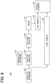
- FIG. 8 is a functional block diagram of a modification of the vehicle diagnosis system in FIG. 2 ;
- FIG. 9 is a flowchart of an operation of the vehicle diagnosis system in FIG. 8 ;
- FIG. 10 is a functional block diagram of another modification of the vehicle diagnosis system in FIG. 2 ;
- FIG. 11 is a functional block diagram of another modification of the vehicle diagnosis system in FIG. 2 ;
- FIG. 12A is a functional block diagram of yet another modification of the vehicle diagnosis system in FIG. 2 ;
- FIG. 12B is a functional block diagram of yet another modification of the vehicle diagnosis system in FIG. 2 ;
- FIG. 12C is a functional block diagram of yet another modification of the vehicle diagnosis system in FIG. 2 ;
- FIG. 12D is a functional block diagram of yet another modification of the vehicle diagnosis system in FIG. 2 ;
- FIG. 13 is a functional block diagram of a vehicle diagnosis system of the vehicle in FIG. 1 in the present disclosure
- FIG. 14 is a flowchart of an operation of the vehicle diagnosis system in FIG. 13 ;
- FIG. 15 is a functional block diagram of a modification of the vehicle diagnosis system in FIG. 13 ;
- FIG. 16 is a flowchart of an operation of the modification of the vehicle diagnosis system in FIG. 15 ;
- FIG. 17 is a flowchart of a modification of the operation in FIG. 14 ;
- FIG. 18 is a flowchart of another modification of the operation in FIG. 14 ;
- FIG. 19 is a flowchart of yet another modification of the operation in FIG. 14 ;
- FIG. 20 is a flowchart of yet another modification of the operation in FIG. 14 ;
- FIG. 21 is a flowchart of yet another modification of the operation in FIG. 14 ;
- FIG. 22 is a flowchart of yet another modification of the operation in FIG. 14 ;
- FIG. 23 is a flowchart of yet another modification of the operation in FIG. 14 ;
- FIG. 24 is a flowchart of yet another modification of the operation in FIG. 14 ;
- FIG. 25 is a flowchart of yet another modification of the operation in FIG. 14 ;
- FIG. 26 is a functional block diagram of a vehicle diagnosis system of the vehicle in FIG. 1 and an external device in the present disclosure
- FIG. 27 is a functional block diagram of the vehicle diagnosis system of the vehicle in FIG. 1 and the external device in the present disclosure
- FIG. 28 is a flowchart of an operation of the vehicle diagnosis system in FIG. 27 ;
- FIG. 29 is a flowchart of an operation of the vehicle diagnosis system in FIG. 27 ;
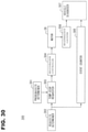
- FIG. 30 is a functional block diagram of the vehicle diagnosis system of the vehicle in FIGS. 26 and 27 in a modification example
- FIG. 31 is a flowchart of an operation of the vehicle diagnosis system in FIG. 32 ;
- FIG. 32 is a functional block diagram of the vehicle diagnosis system of the vehicle in FIGS. 26 and 27 in another modification example;
- FIG. 33 is a functional block diagram of the vehicle diagnosis system of the vehicle in FIGS. 26 and 27 in yet another modification example;
- FIG. 34 is a functional block diagram of the vehicle diagnosis system of the vehicle in FIGS. 26 and 27 in still yet another modification example
- FIG. 35 is a functional block diagram of the vehicle diagnosis system of the vehicle in FIGS. 26 and 27 in still yet another modification example
- FIG. 36 is a block diagram of a vehicle diagnosis system implemented in a vehicle in the present disclosure.
- FIG. 37 is a schematic diagram of functional blocks of the vehicle diagnosis system implemented in the vehicle of FIG. 36 ;
- FIG. 38 is a flowchart of an operation of the vehicle diagnosis system in FIG. 37 ;
- FIG. 39 is a schematic diagram of functional blocks of the vehicle diagnosis system implemented in the vehicle of FIG. 36 ;
- FIG. 40 is a schematic diagram of functional blocks of the vehicle diagnosis system implemented in the vehicle of FIG. 36 ;
- FIG. 41 is a schematic diagram of functional blocks of the vehicle diagnosis system implemented in the vehicle of FIG. 36 ;
- FIG. 42 is a schematic diagram of functional blocks of the vehicle diagnosis system implemented in the vehicle of FIG. 36 ;
- FIG. 43 is a flowchart of an operation of the vehicle diagnosis system in FIG. 42 ;
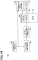
- FIG. 44 is a schematic diagram of functional blocks of the vehicle diagnosis system implemented in the vehicle of FIG. 36 ;
- FIG. 45 is a schematic diagram of functional blocks of the vehicle diagnosis system implemented in the vehicle of FIG. 36 .
- An external device C shown in FIG. 1 is disposed in data-communicable manner with a vehicle V, which is a so-called hybrid vehicle, via a communication channel that is either a wired communication or a wireless communication.
- the vehicle V has an engine 10 (i.e., a multi-cylinder gasoline engine of a spark ignition type) installed therein.
- a throttle valve 12 of the electric drive type is disposed in an inlet pipe 11 of the engine 10 .
- an injector 13 as a means to inject gasoline fuel is disposed.
- a spark plug 15 and an igniter 16 which applies high voltage for an ignition of the spark plug 15 are disposed on each cylinder as an ignition means of the engine 10 .
- An intake valve 17 and an exhaust valve 18 are respectively disposed in the intake port and in the exhaust port.
- a catalytic converter 23 as an exhaust emission purifier is disposed in an exhaust pipe 21 of the engine 10 .
- the catalytic converter 23 has a three-way catalyst, for example, and it is configured so that the detrimental constituent (i.e., HC, CO, NOx) in the exhaust gas is purified when the exhaust gas passes therethrough.
- a transmission 26 containing a power distribution device with a planetary gear mechanism is connected to a crank shaft 25 of the engine 10 .
- a motor 28 which can operate as an electric motor and as a generator is connected to the transmission 26 via a gear shaft 27 .
- a wheel (i.e., a driving wheel) 33 is connected via an output shaft 29 , a differential gear 31 , and a drive shaft 32 . That is, the transmission 26 is configured to be capable of outputting an output power of the engine 10 and an output power of the motor 28 to the same drive shaft 32 .
- the motor 28 is connected to a high voltage battery 35 via an inverter 34 .
- the inverter 34 is used for charging an electric power to the high voltage battery 35 , after converting the electric power generated by the motor 28 from a direct current to an alternating current.
- the inverter 34 is used to convert the electric power outputted from the high voltage battery 35 from the direct current to the alternating current, and to output the converted electric power to the motor 28 .
- the inlet pipe 11 has, disposed thereon, an air flow meter 41 a , an intake air temperature sensor 41 b , and a throttle position sensor 41 c .
- the air flow meter 41 a is disposed so that the output (of the meter 41 a ) corresponds to the mass flow rate (Ga) of the intake air which passes through the inlet pipe 11 .
- the intake air temperature sensor 41 b is disposed so that the output corresponds to the temperature (Tin) of the above-mentioned intake air.
- the throttle position sensor 41 c is disposed at a position corresponding to the throttle valve 12 so that the output corresponds to a throttle opening TA which is an opening (i.e., a rotation angle) of the throttle valve 12 .
- an A/F sensor 41 d On the exhaust pipe 21 , an A/F sensor 41 d , a catalyst temperature sensor 41 e , and an exhaust gas temperature sensor 41 f are provided.
- the A/F sensor 41 d is an oxygen density sensor which produces an output corresponding to the oxygen density in the exhaust gas, and is disposed at an upstream position of the catalytic converter 23 on the exhaust pipe 21 .
- the catalyst temperature sensor 41 e is disposed on the catalytic converter 23 so that the output of the sensor 41 e corresponds to the temperature (Tc) of the catalytic converter 23 .
- the exhaust gas temperature sensor 41 f is provided so that the output of the sensor 41 f corresponds to the temperature (Tex) of the exhaust gas which passes through the exhaust pipe 21 .
- the transmission 26 is equipped with a mission oil temperature sensor 41 g .
- the mission oil temperature sensor 41 g is disposed so that the output corresponds to the operating oil temperature inside the transmission 26 (Tm).
- the engine 10 is equipped with a cooling water temperature sensor 41 h , and a crank angle sensor 41 k .
- the cooling water temperature sensor 41 h is disposed so that the output corresponds to a cooling water temperature (Tw) of the engine 10 .
- the crank angle sensor 41 k is disposed on a crank case of the engine 10 so that an output signal therefrom includes a narrow width pulse at every 10 degree rotation of the crank shaft 25 and a broad width pulse at every 360 degree rotation of the crank shaft 25 , which may be mainly used for a detection of an engine rotation number Ne.
- the vehicle V is equipped with a vehicle speed sensor 41 m , and a brake pressure sensor 41 n .
- the vehicle speed sensor 41 m is disposed so that the output corresponds to a travel speed (ve) of the vehicle V.
- the brake pressure sensor 41 n is disposed so that the output corresponds to a brake oil pressure (Pbr) which is a pressure of a hydraulic fluid supplied to a brake caliper (not illustrated) from a brake actuator (not illustrated).
- Pbr brake oil pressure
- the vehicle V is equipped with a shift position sensor 41 p , a brake sensor 41 r , an accelerator opening sensor 41 s and an open-close sensor 41 t .
- the shift position sensor 41 p is disposed so that the output corresponds to an operation state of the gearshift (not illustrated) disposed near the driver's seat of the vehicle V.
- the brake sensor 41 r is disposed so that the output corresponds to an operation amount of a brake pedal (not illustrated).
- the accelerator opening sensor 41 s is disposed so that the output corresponds to an accelerator opening Acc which is an operation amount of an accelerator (not illustrated).
- the open-close sensor 41 t is disposed so that the output corresponds to an open-close state of a door of the vehicle V or of a hood of the vehicle V (not illustrated).
- a voltage sensor 41 v and an electric current sensor 41 x are electrically connected to the high voltage battery 35 .
- the voltage sensor 41 v is disposed so that the output corresponds to a voltage Vb between the terminals of the high voltage battery 35 .
- the electric current sensor 41 x is disposed so that the output corresponds to charge and discharge currents Ib of the high voltage battery 35 .
- a start switch 42 which may also be called as an ignition switch, is provided in the vehicle V.
- the start switch 42 is a switch operated for a switch ON and a switch OFF of the vehicle V (i.e., a hybrid system), and is disposed near the driver's seat.
- the engine ECU 51 and the hybrid ECU 52 are basically comprised of a microcomputer that has, as well-known, CPU, ROM, RAM, etc., respectively, and perform various controls about an operation of the vehicle V by executing various kinds of control programs memorized in the ROM.
- the engine ECU 51 is electrically connected to the above-mentioned sensors, except for the voltage sensor 41 v and the electric current sensor 41 x .
- the hybrid ECU 52 is electrically connected to the voltage sensor 41 v , the electric current sensor 41 x , and to the start switch 42 .
- the engine ECU 51 and the hybrid ECU 52 are electrically connected with each other for an exchange of signals.
- the engine ECU 51 receives, as an input signal, a signal outputted from the above-mentioned sensors and the hybrid ECU 52 which are electrically connected thereto (i.e., to the ECU 51 ), and controls a drive of each part (i.e., the injector 13 , igniter 16 etc.) of the engine 10 based on such input signal.
- the hybrid ECU 52 receives an output signal of the above-mentioned sensors, except for the voltage sensor 41 v and the electric current sensor 41 x , via the engine ECU 51 , and (directly) receives an output signal outputted from the voltage sensor 41 v and the electric current sensor 41 x , and, based on those received signals, performs an operation control of the motor 28 , an operation control of the inverter 34 , a charge and discharge control of the high voltage battery 35 , etc.
- the engine ECU 51 and the hybrid ECU 52 perform, in cooperation with each other (i.e., through an exchange of a control signal, data, etc.), various controls such as a travel mode control, a temporal stop/restart control of the engine 10 etc. regarding the vehicle V (i.e., a hybrid system). That is, the vehicle V is provided with a temporal stop function of the engine 10 in a hybrid system (i.e., a function that temporarily stops the engine 10 when a prescribed condition is satisfied).
- a “temporal engine stop function” is a function to temporarily stop the engine when a prescribed condition is satisfied.
- a temporal stop of an engine may simply be designated as “a temporal stop” or “a temp-stop” for brevity.
- a temporal engine stop function may simply be designated as “a temporal stop function” or a “temp-stop function” for brevity.
- a vehicle diagnosis system 100 for greenhouse gas emission amount reduction in the first embodiment of the present disclosure is described in terms of how it performs a process about diagnosis of the vehicle V of FIG. 1 .
- a vehicle diagnosis system 100 has a prerequisite determiner 101 , a requisite determiner 102 , a temp-stop requester 103 , a stop-start actuator 104 (i.e., a temporal-stop and restart section 104 in a very true translation), an event counter 105 , a stop counter 106 , and a vehicle diagnose 107 .
- the prerequisite determiner 101 equivalent to a “prerequisite determiner” of the present disclosure is provided so that formation, or a satisfaction, of the prerequisite for performing a temporal stop may be determined.
- a “prerequisite” is a condition, or a state of the vehicle V, that should normally, i.e., when having no abnormality/failure, be satisfied after a preset time from a start of the engine 10 , which may be at least one of the followings.
- Tw>Tw0 i.e., Tw0: a specified value
- Tm>Tm0 i.e., Tm0: a specified value
- SOC of the high voltage battery 35 is in an estimable/foreseeable state (SOC: State Of Charge),
- Vb>Vb0 i.e., Vb0: a specified value
- the prerequisite determiner 101 determines “the satisfaction of the prerequisite” when all of the conditions (1)-(8) mentioned above are satisfied.
- the item (5) “SOC of the high voltage battery 35 is in an estimable/foreseeable state” may be rephrased as a condition in which the high voltage battery 35 is substantially in a full charge state at least once (i.e., a charging current ⁇ a predetermined threshold value). That is, SOC can be estimated, as everyone knows, based on “a relation between a charging current and SOC.” Now, when SOC is low, “the relation between the charging current and SOC” may vary drastically under the influence of the temperature etc., which does not enables an accurate estimation of SOC.
- a standard procedure of estimating SOC is that, (i) a battery is once brought to a full charge state, and (ii) an SOC estimation value of such a full charge state is obtained, and (iii) such an SOC estimation value is updated according to the charging and discharging currents of the high voltage battery 35 .
- the requisite determiner 102 equivalent to a “requisite determiner” or an “operation condition determiner” of the present disclosure is provided so that formation, or a satisfaction, of an operation condition (i.e., requisite, or a condition, for a temporal stop which is different from the above-mentioned prerequisite) may be determined
- the “operation condition” is a state of drive operation of the vehicle V for performing a temporal stop, based on an assumption that the “prerequisite” is (already) satisfied/satisfied, which may be at least one of the followings.
- the requisite determiner 102 determines “the satisfaction of the requisite” when all of the conditions (i)-(v) mentioned above are satisfied.
- the temp-stop requester 103 When satisfaction of a prerequisite is determined by the prerequisite determiner 101 and satisfaction of an operation condition (i.e., requisite) is determined by the requisite determiner 102 , the temp-stop requester 103 is configured to issue a temporal stop request (i.e., a signal for performing a temporal stop process of the engine 10 ). Based on a reception state of the temporal stop request from the temp-stop requester 103 , the stop-start actuator 104 is configured to temporarily stop the engine 10 and restarts the engine 10 .
- a temporal stop request i.e., a signal for performing a temporal stop process of the engine 10 .
- the event counter 105 is equivalent to an “event counter” of the present disclosure is provided so that an event counted value Creq may be obtained.
- an “event counted value Creq” is a counted value about the frequency of, i.e., the number or quantity of, “expected events.”
- the “expected event” is an event in which satisfaction of the operation condition (i.e., requisite) is determined by the requisite determiner 102 in a prerequisite satisfaction expected state, i.e., in which satisfaction of the prerequisite is expected.
- the “prerequisite satisfaction expected state” which is the condition for obtainment of the event counted value Creq shall mean a time lapse state in which a predetermined time has passed from a start of the engine 10 .
- the “predetermined time” should be respectively different for a restart-from-temp-stop case and for other cases (i.e., typically, for a cold-start case). Therefore, in the present embodiment, the event counter 105 switches a threshold value for the restart-from-temp-stop case and for the other cases, for the determination whether the predetermined time has passed from a start of the engine 10 .
- the stop counter 106 is equivalent to an “episode counter” or an “operation counter” of the present disclosure is provided so that an operation counted value Cstp may be obtained.
- the “operation counted value Cstp” is a counted value about the frequency, or the number or quantity of, temporal stop operations by the stop-start actuator 104 , i.e., how many times an operation is performed for a temporal stop.
- the prerequisite determiner 101 the requisite determiner 102 , the temp-stop requester 103 , the event counter 105 , and the stop counter 106 are provided in the hybrid ECU 52 . Further, the stop-start actuator 104 is provided in the engine ECU 51 .
- the vehicle diagnoser 107 is configured to send the event counted value Creq obtained by the event counter 105 and the operation counted value Cstp obtained by the stop counter 106 to the external device C from the vehicle V (refer to FIG. 1 ).
- the vehicle diagnoser 107 is provided with a communicator 107 b .
- the communicator 107 b which is provided in the hybrid ECU 52 , sends the newest/latest value of the event counted value Creq obtained by the event counter 105 and the newest value of operation counted value Cstp obtained by the stop counter 106 to the external device C according to a request from the external device C, or the like.
- These newest values transmitted to the external device C by the communicator 107 b may be memorized by the event counter 105 , or by the stop counter 106 , or may also be memorized by a memory provided in the vehicle diagnoser 107 .
- the event counter 105 obtains the event counted value Creq by counting the number of trips in which the expected event happened. Further, the stop counter 106 obtains the operation counted value Cstp by counting the number of trips in which a temporal stop (causing) operation had happened (i.e., causing a temporal stop operation to occur).
- a “trip” shall mean a period from a switching OFF to ON of the start switch 42 to a next switching OFF to ON of the start switch 42 .
- the engine ECU 51 and the hybrid ECU 52 control an operation of each part of the vehicle V (i.e., a hybrid system) based on the various states etc. of the vehicle V grasped by the output signal of the above-mentioned multiple sensors, exchanging various signals among the two (ECUs).
- the hybrid ECU 52 obtains the various states of the vehicle V, etc., based on the input signals from the voltage sensor 41 v , the electric current sensor 41 x , the start switch 42 etc., and also based on the signal inputted by the signal exchange with the engine ECU 51 , etc., for example.
- the hybrid ECU 52 sets up a travel mode (i.e., including a temporal stop/restart of the engine 10 ) of the vehicle V, taking the fuel mileage of the engine 10 into consideration and based on the various states etc. of the vehicle V.
- a travel mode i.e., including a temporal stop/restart of the engine 10
- the engine ECU 51 performs a drive control of the engine 10 according to the travel mode set up (i.e., determined) by the hybrid ECU 52 . That is, for example, the engine ECU 51 performs various controls (i.e., a fuel injection control including a so-called fuel cut, an ignition control, etc.) of the engine 10 during a drive period of the engine 10 based on the drive state or the like of the vehicle V.
- the hybrid ECU 52 calculates a remaining amount of charge (SOC) of the high voltage battery 35 based on the charge and discharge currents detected by the electric current sensor 41 x . Further, the hybrid ECU 52 controls the drive of the motor 28 , the inverter 34 etc. based on the drive state of the vehicle V, a remaining amount of charge of the high voltage battery 35 , or the like.
- a temporal stop/restart control of the engine 10 is described in more details.
- whether the prerequisite for performing a temporal stop is satisfied is determined by the prerequisite determiner 101 .
- whether the above-mentioned operation condition (i.e., requisite) is satisfied is determined by the requisite determiner 102 .
- a temporal stop request is issued by the temp-stop requester 103 . If such a temporal stop request is issued, the stop-start actuator 104 temporarily stops the engine 10 as a result of the temp-stop function being performed.
- the prerequisite satisfied determination by the prerequisite determiner 101 should be established after a predetermined time from a start of the engine 10 , as mentioned above. Therefore, if the above-mentioned operation condition (i.e., requisite) is satisfied after a predetermined time from a start of the engine 10 (with a reservation that “a predetermined time” is different for a restart-after-temp-stop case and for other cases), the engine 10 is temporarily stopped and a greenhouse gas reduction effect should be achieved.
- the above-mentioned operation condition i.e., requisite
- the temporal stop of the engine 10 may be not performed, or may be hindered due to unknown abnormality/failure, even though (i) the prerequisite has already been satisfied and (ii) the above-mentioned operation condition (i.e., requisite) has already been satisfied, which results in cancelling the greenhouse gas reduction effect (i.e., the reduction effect will not be fully/preferably achieved).
- Driving the vehicle V continued for a long time in such a state i.e., a temp-stop function disabled state, is problematic from a viewpoint of an environmental impact. Therefore, when such an abnormality (i.e., failure) is caused, the driver (of the vehicle V) should be prompted to fix the vehicle as soon as possible.
- the event counter 105 counts a value regarding the number of occurrences of the expected event (i.e., more practically, the number of trips in which the expected event happened), and obtains the event counted value Creq. Specifically, the event counter 105 increments, i.e., counts up by only one count, the event counted value Creq, when an expected event occurs even once in the current trip. Further, the event counter 105 switches a threshold value for a restart-after-temp-stop case and for other cases, for a determination of a condition, i.e., whether a predetermined time has passed from a start of the engine 10 , which is, in other words, a “prerequisite satisfaction expected state.”
- the stop counter 106 obtains the operation counted value Cstp, by counting a value regarding the number of temporal stop (causing) operations (i.e., the number of trips in which the stop-start actuator 104 has performed a temporal stop (causing) operation). Specifically, the stop counter 106 increments, i.e., counts up only one count, the operation counted value Cstp, when the above-mentioned operation occurs even once in the current trip.
- the event counted value Creq and the operation counted value Cstp are outputted to the external device C by the communicator 107 b provided on a vehicle V side.
- the vehicle diagnosis system 100 enables a manufacturer, a seller, a maintenance personnel or the like of the vehicle V to quickly and appropriately obtain a state of abnormality (i.e., failure) of the vehicle V which leads to an increase of the greenhouse gas emitted from the vehicle V in a market.
- the vehicle diagnosis system 100 in the second embodiment of the present disclosure is understood as being configured to perform a diagnosis of the vehicle V (see also FIG. 1 ).
- vehicle diagnosis system 100 has the prerequisite determiner 101 , the requisite determiner 102 , the temp-stop requester 103 , the stop-start actuator 104 , the event counter 105 , the stop counter 106 , and the vehicle diagnoser 107 .
- the prerequisite determiner 101 , the requisite determiner 102 , the temp-stop requester 103 , the stop-start actuator 104 , the event counter 105 , and the stop counter 106 are the same as those of the above-mentioned first embodiment.
- the vehicle diagnoser 107 is provided with a greenhouse gas increase determiner 107 c .
- a greenhouse gas increase determiner 107 c is configured to detect/determine, based on the newest value (i.e., a value received from the communicator 107 b ) of the event counted value Creq and the operation counted value Cstp, whether “the abnormality of a temporal stop function in a mode by which a greenhouse gas reduction effect is reduced/cancelled” is caused. In the following, such determination is designated as “a greenhouse gas increase determination.”
- the determination by the prerequisite determiner 101 whether the prerequisite has been satisfied is, in a normal operation, i.e., having no abnormality/failure, is established as satisfied after a predetermined time from a start of the engine 10 . Therefore, when the prerequisite is satisfied after a predetermined time from a start of the engine 10 (with a reservation that “a predetermined time” is different for a restart-after-temp-stop case and for other cases), the temporal stop of the engine 10 is (i.e., should be) performed and the greenhouse gas reduction effect should be achieved/exerted.
- the temporal stop of the engine 10 may be not performed, or may be hindered due to some/unknown abnormality/failure, even though (i) the prerequisite has already been satisfied and (ii) the above-mentioned operation condition (i.e., requisite) has already been satisfied, which results in cancelling the greenhouse gas reduction effect (i.e., the reduction effect will not be fully/preferably achieved).
- Driving the vehicle V continued for a long time in such a state i.e., a temp-stop function disabled state, is problematic from a viewpoint of an environmental impact.
- the vehicle diagnose 107 i.e., the greenhouse gas increase determiner 107 c ) performs the greenhouse gas increase determination based on an occurrence state of a temporal stop (causing) operation.
- the event counter 105 counts a value regarding the number of occurrence times of an expected event (i.e., the number of trips in which the expected event had happened, more specifically), and obtains the event counted value Creq. Specifically, the event counter 105 increments, or counts up, by only one count, the event counted value Creq when an expected event occurs even once in the current trip. Further, the event counter 105 switches a threshold value for a restart-after-temp-stop case and for other cases, for a determination of a condition, i.e., whether a predetermined time has passed from a start of the engine 10 , which is, in other words, a “prerequisite satisfaction expected state.”
- the stop counter 106 obtains the operation counted value Cstp, by counting a value regarding the number of temporal stop (causing) operations (i.e., the number of trips in which the stop-start actuator 104 has performed a temporal stop (causing) operation). Specifically, the stop counter 106 increments, i.e., counts up only one count, the operation counted value Cstp, when the above-mentioned operation occurs even once in the current trip. Then, the greenhouse gas increase determiner 107 c performs the greenhouse gas increase determination, based on the newest values of the event counted value Creq and the operation counted value Cstp.
- An initialization routine shown in FIG. 4 is started by a main CPU in the hybrid ECU 52 immediately after a start of the hybrid system by the start switch 42 .
- predetermined clear conditions e.g., input of a clear command from the external device C, etc.
- Step 407 whether the operation condition (i.e., requisite) is satisfied is determined.
- the process proceeds to above-mentioned step 405 , such procedure is once finished.
- the process proceeds to Step 409 .
- Step 409 whether the prerequisite is satisfied or not is determined.
- Step 409 YES
- the process proceeds to Step 411 and a temporal stop request is set to provide a request for a temporary stop of the engine.
- Step 409 NO
- the process proceeds to Step 413 and a temporal stop request is canceled.
- Step 415 whether a predetermined time has pass after a start of the engine 10 is determined.
- Step 415 is a determination process regarding an “expected event” or a “prerequisite satisfaction expected state.”
- the process of Step 417 is skipped and the process proceeds to Step 419 thereafter.
- the threshold value of the determination of whether a predetermined time has passed from a start of the engine 10 is switched for a restart-after-temp-stop case and for other cases.
- a threshold value for the restart-after-temp-stop case is set as a value smaller than a threshold value for the other cases (see a setting process of a threshold value t0 in a flowchart of FIG. 7 concerning the embodiment mentioned later).
- Step 419 whether the count request flag Fc is changed to the set state from the reset state by a current execution of the procedure is determined.
- the process proceeds to Step 423 .
- Step 419 determines whether the determination of Step 419 is “NO”, the process of Step 421 is skipped and the process proceeds to Step 423 thereafter.
- Step 423 YES
- Steps 427 and 429 the greenhouse gas increase determination is performed based on a newest value of the event counted value Creq and a newest value of the operation counted value Cstp. Specifically, it is first determined in Step 427 whether the value (i.e., a ratio) which is derived by dividing the operation counted value Cstp by the event counted value Creq is smaller than a predetermined threshold value K0. After the process of Step 429 is performed according to the determined result in Step 427 , the procedure is once finished.
- the value i.e., a ratio
- Step 427 YES
- Step 427 NO
- whether the abnormality about the temporal stop function in the mode by which a greenhouse gas reduction effect is reduced is caused is determined based on an occurrence state of the temporal stop (causing) operation in the prerequisite satisfaction expected state.
- a determination of occurrence of such an abnormality may enable a quick fix of the abnormality as soon as possible by notifying a driver etc. about such an abnormality. Therefore, according to the present embodiment, the system 100 reduces the environmental impact caused by the vehicle V having the engine 10 as much as possible.
- the vehicle diagnosis system 100 in the third embodiment of the present disclosure is provided with the prerequisite determiner 101 , the requisite determiner 102 , the temp-stop requester 103 , the stop-start actuator 104 , and a vehicle diagnoser 108 as shown in FIG. 6 .
- the prerequisite determiner 101 , the requisite determiner 102 , the temp-stop requester 103 , and the stop-start actuator 104 are the same as those of the above-mentioned first embodiment.
- the vehicle diagnoser 108 is disposed in the hybrid ECU 52 , i.e., on a vehicle V side. Such a vehicle diagnoser 108 performs the greenhouse gas increase determination based on the determination state in the prerequisite determiner 101 . That is, the vehicle diagnoser 108 is provided with a greenhouse gas determination section (refer to greenhouse gas determination section 107 c in FIG. 3 ) as well as the vehicle diagnoser 107 in the second embodiment.
- the vehicle diagnoser 108 determines whether the abnormality about the temporal stop function in the mode by which a greenhouse gas reduction effect is reduced is caused when satisfaction of the prerequisite is not determined by the prerequisite determiner 101 even after satisfaction of a condition of a predetermined time having passed after a start of the engine 10 . Further, the vehicle diagnoser 108 switches a threshold value (i.e., a threshold value t0 in a flowchart of FIG. 7 ) for determining whether a condition of a predetermined time having passed after a start of the engine 10 is satisfied for a restart-after-temp-stop case and for other cases.
- a threshold value i.e., a threshold value t0 in a flowchart of FIG. 7
- Step 631 YES
- Step 631 NO
- Step 631 NO
- Step 631 YES
- Step 635 whether a stop the engine 10 is “a temporal stop,” i.e., a stop of the engine 10 is caused by the temporal stop request issued by the temp-stop requester 103 .
- Step 635 YES
- Step 635 NO
- such value t02 is obtained from a map (i.e., from a look-up table) which defines t0 values with parameters such as a cooling water temperature (Tw), an intake air temperature (Tin) etc. of the engine 10 .
- a map i.e., from a look-up table
- Tw cooling water temperature
- Tin intake air temperature
- Step 631 NO
- the process proceeds to Step 641 , and an increment of the engine operation time counter ts is performed.
- Step 643 whether the engine operation time counter ts is greater than the threshold value t0 is determined.
- the threshold value t0 is switched for a restart-after-temp-stop case and for other cases by the processes after the above-mentioned step 635 . Therefore, the process in Step 643 determines whether a predetermined time has passed from a start of the engine 10 with respectively different thresholds for the restart-after-temp-stop case and for the other cases.
- Step 643 NO
- Step 643 YES
- the procedure is once finished (i.e., finished for the current cycle).
- Step 645 whether a satisfaction of the prerequisite is determined by the prerequisite determiner 101 is determined.
- the process of Step 647 is skipped.
- the abnormality when, due to some failure (e.g., degradation of the high voltage battery 35 , failure of the cooling water temperature sensor 41 h , etc.) the prerequisite will not be satisfied, the abnormality may be quickly fixed as soon as possible by notifying a driver etc. of such prerequisite unsatisfiable state.
- some failure e.g., degradation of the high voltage battery 35 , failure of the cooling water temperature sensor 41 h , etc.
- the system 100 reduces the environmental impact caused by the vehicle V having the engine 10 as much as possible.
- the present disclosure is not limited to the configuration of each embodiment mentioned above.
- the present disclosure is not limited to a hybrid vehicle which is mentioned above. That is, the present disclosure is widely applicable to the various vehicles, which may have an internal-combustion engine (not limited to a gasoline engine) as its source of thrust power.
- a temporal stop function is called an “idle stop function.”
- a temporal stop of the engine 10 in a hybrid vehicle may also be called as an “idle stop” depending on a situation.
- the engine ECU 51 and the hybrid ECU 52 may have one body configuration. Further, in each of the various configurations of the above-mentioned embodiments, a parameter obtained by using a certain sensor may be replaced with other parameters derived from outputs of other sensors, or on-board estimation values derived from outputs of other sensors. More practically, a brake oil pressure Pbr may be replaceable with a negative pressure, for example.
- the prerequisite determiner 101 determines “the satisfaction of the prerequisite” when all of the eight conditions are satisfied.
- the prerequisite satisfaction conditions may have three conditions in addition to the above-mentioned eight conditions. More practically, the following three conditions may be added, that is,
- the greenhouse gas increase determiner 107 c may be disposed on a vehicle V side, or may be disposed on the external device C, or may be disposed in a server etc. which is connected to the external device C by the wired channel or the wireless channel so that the information obtained from the external device C is appropriately processed.
- the parameter used for the determination of the prerequisite in the prerequisite determiner 101 may be selected from among the above-mentioned items, and may be additionally employed from the items other than the above. Further, any requisite mentioned above may be used as the prerequisite instead. Such a switching of requisite to prerequisite may apply the determination of the requisite by the requisite determiner 102 .
- the above-mentioned condition (v) about the brake oil pressure Pbr is used as the prerequisite rather than the requisite
- the above-mentioned requisite (i)-(iv) correspond to the operation state of the vehicle V by the driver or occupants (i.e., operation state realized by human).
- the above-mentioned prerequisites (1)-(8) and the prerequisite (v) correspond to the drive state (i.e., the operation state) of the vehicle V which is caused by the operation state of the vehicle V by the driver or occupants.
- the number of times by which the temporal stop operation is performed by the stop-start actuator 104 is counted as the number of temporal stop (causing) operations.
- the present disclosure is not limited to such mode.
- the number of times by which the engine 10 has actually stopped, the number of times by which the temporal stop request has been issued, and the number of times by which the fuel cut is caused by the temporal stop request may also be counted as the number of temporal stop (causing) operations.
- the stop counter 106 may count the number of times by which the temporal stop request is issued by the temp-stop requester 103 as the operation counted value Cstp.
- the stop counter 106 may count the number of times by which the engine 10 has actually stopped as the operation counted value Cstp.
- stop counter 106 may count the number of times by which the fuel cut is caused by the temporal stop request as the operation counted value Cstp.
- the counting subject may be switched to the number of voidings of the temporal stop (causing) operation during (i.e., in spite of) the occurrence of the (expected) event.
- the abnormality is determined by the number of occurrences of the expected event and the number of voidings.
- the abnormality is determined by the number of occurrences of the expected event and the number of temporal stop (causing) operations in first and second embodiments, the abnormality may also be determined differently, i.e., by the number of temporal stop (causing) operations and the number of voidings of the temporal stop (causing) operation.
- the event counted value Creq is counted up only by one (i.e., incremented).
- the operation counted value Cstp is counted up only by one (i.e., incremented).
- the present disclosure is not limited to such mode.
- FIG. 8 corresponds to a modification of the vehicle diagnosis system in FIG. 2 . That is, in the modification of FIG. 8 , the event counter 105 obtains the event counted value Creq whenever an expected event occurs, i.e., by actually counting the number of the expected events. The stop counter 106 obtains the operation counted value Cstp whenever the temporal stop (causing) operations occurs, i.e., by actually counting the number of temporal stop (causing) operations.
- the vehicle diagnoser 109 is configured to perform the greenhouse gas increase determination, similarly to the vehicle diagnoser 107 (refer to FIG. 3 ) in the above-mentioned second embodiment, based on the event counted value Creq obtained by the event counter 105 and the operation counted value Cstp obtained by the stop counter 106 . That is, the vehicle diagnoser 109 is provided with the greenhouse gas determination section (refer to the greenhouse gas determination section 107 c in FIG. 3 ) just like the vehicle diagnoser 107 in the second embodiment.
- the procedure shown in FIG. 9 is a concrete example of the operation of the modified configuration described above.
- the procedure is performed at predetermined intervals after a start of the hybrid system by the start switch 42 .
- the procedure in FIG. 9 is similar to the one in FIG. 5 . However, unlike the procedure in FIG. 5 , the execution of an initialization routine (refer to FIG. 4 ) or the temp-stop already-counted flag Fd (refer to FIGS. 4 and 5 ) are not required.
- Step 807 whether the operation condition (i.e., requisite) is satisfied is determined.
- the procedure is once finished.
- Step 807 YES
- Step 809 whether the prerequisite is satisfied is determined.
- the process proceeds to Step 811 and a temporal stop request is set.
- Step 809 NO
- the process proceeds to Step 813 and a temporal stop request is canceled.
- Step 811 the process of Step 811 or the process of 813 is performed according to the determined result of Step 809 .
- the process proceeds to Step 815 .
- Step 815 whether a predetermined time has passed from a start of the engine 10 is determined.
- Step 815 YES
- the process proceeds to Step 817 , and the count request flag Fc is set
- Step 819 whether the count request flag Fc is changed to the set state from the reset state by a current execution of the procedure is determined.
- the process proceeds to Step 823 .
- Step 819 determines whether the determination of Step 819 is “NO”, the process of Step 821 is skipped and the process proceeds to Step 823 thereafter.
- Step 823 whether an “edge” which indicates that an engine rpm Ne is equal to zero is detected is determined.
- Step 823 YES
- the process proceeds to Step 827 .
- Step 825 the operation counted value Cstp is counted up (i.e., incremented).
- Step 823 NO
- the process of Step 825 is skipped and the process proceeds to Step 827 .
- Steps 827 and 829 the greenhouse gas increase determination is performed based on the event counted value Creq and the operation counted value Cstp. Specifically, it is first determined in Step 827 whether the value (i.e., a ratio) which is derived by dividing the operation counted value Cstp by the event counted value Creq is smaller than a predetermined threshold value K0. After the process of Step 829 is performed according to the determined result in Step 827 , the procedure is once finished.
- the value i.e., a ratio
- Step 827 YES
- Step 827 NO
- the determination by the “number of times” is normal (i.e., indicating normal operation)
- the greenhouse gas reduction effect becomes insufficient as a result of decrease of an actual temporal stop time (i.e., duration) of the engine 10 . Therefore, the determination by the “number of times” may be replaced with the determination by “time” (i.e., duration).
- FIG. 10 corresponds to a modification of the vehicle diagnosis system in FIG. 2 . That is, in the modification shown in FIG. 10 , the vehicle diagnosis system 100 has the prerequisite determiner 101 , the requisite determiner 102 , the temp-stop requester 103 , the stop-start actuator 104 , the vehicle diagnoser 109 , the event time counter 115 , and the stop time counter 116 .
- FIG. 11 is similar to FIG. 10 but includes an idle time counter 118 rather than an event time counter 115 .
- the even time counter 115 is configured to obtain the event counted value Creq as a counted value of an accumulated time of occurrences of the “expected event”.
- the stop time counter 116 is configured to obtain the operation counted value Cstp as a counted value of an accumulated time of occurrences of the temporal stop (causing) operation.
- the accumulated amount of savable fuel is calculated by a time-integration of a per-unit-time idle time fuel consumption amount (calculated based on a water temperature table) for/during an occurrence duration of the expected events.
- the accumulated amount of saved fuel is calculated by a time-integration of a per-unit-time idle time fuel consumption amount (calculated based on a water temperature table) for/during an occurrence of the temporal stop (causing) operation during an occurrence of the expected events.
- the accumulated amount of saved fuel is calculated by a time-integration of a per-unit-time idle time fuel consumption amount (calculated based on a water temperature table) for/during a voiding duration of the temporal stop (causing) operation during an occurrence of the expected events.
- the amount may be calculated by a time-integration of an actual injection amount for/during a voiding duration of the temporal stop (causing) operation during an occurrence of the expected events.
- the conditions for obtainment of the event counted value Creq i.e., a “prerequisite satisfaction expected state” is not limited only to a state of lapse of a predetermined time from a start of the engine 10 . That is, the others of the above-mentioned prerequisites may be used as such conditions.
- the vehicle diagnoser 109 may be a means of communications (refer to the communicator 107 b in FIG. 2 ) just like the vehicle diagnoser 107 in the first embodiment.
- FIG. 12A shows an example of an in-part modification of the configuration of FIG. 8 .
- the event counter 105 is deleted, and the accel-off counter 121 is newly added, for counting the number of times by which an accelerator is turned off, i.e., having an accelerator opening Acc smaller than a preset threshold Acc0.
- a non-stop counter 119 is added, for counting the number of times by which the engine rpm Ne of the engine 10 stays to be equal to or greater than a specified value Ne0 during an accelerator-off period (i.e., the counter 119 counts the number of not performing a temporal stop of the engine).
- two values may be used for determining whether the abnormality about the temporal stop function in the mode by which a greenhouse gas reduction effect is reduced is caused.
- a quotient of two values outputted to vehicle diagnoser 109 is used for the determination, i.e., whether the quotient is smaller than the preset threshold is determined.
- the abnormality about a temporal stop function is determined.
- the “number of times” determination may be replaced with the “time (i.e., duration)” determination.
- the engine may be immediately (e.g., automatically) restarted (for preventing a further voltage lowering in the battery).
- Such an abnormality may also be covered/detectable by using the present embodiment, as an abnormality about the temporal stop of the engine 10 .
- the accel-off counter 121 may be replaced with a savable fuel amount estimator, which is not illustrated.
- the savable fuel amount estimator calculates an amount of savable fuel from a temporal stop of the engine 10 during all accelerator-off periods. Even in such a configuration, with the help of the operation of base configuration in FIG. 12A , whether the abnormality about the temporal stop function in the mode by which a greenhouse gas reduction effect is reduced is caused is detectable, based on the occurrence state of the temporal stop operation.
- the non-stop counter 119 may be replaced with a used fuel amount calculator 120 .
- the used fuel amount calculator 120 calculates/accumulates an amount of used fuel by idling of the engine 10 during an accelerator-off period. Even in such a configuration, with the help of the operation of base configuration in FIG. 12A , whether the abnormality about the temporal stop function in the mode by which a greenhouse gas reduction effect is reduced is caused is detectable, based on the occurrence state of the temporal stop operation.
- the stop counter 106 may be replaced with a saved fuel amount calculator.
- the saved fuel amount calculator calculates/accumulates an amount of saved fuel saved by performing a temporal stop of the engine 10 during an accelerator-off period. Even in such a configuration, with the help of the operation of base configuration in FIG. 12A , whether the abnormality about the temporal stop function in the mode by which a greenhouse gas reduction effect is reduced is caused is detectable, based on the occurrence state of the temporal stop operation.
- the accel-off counter 121 may be replaced with the savable fuel amount estimator 121 c
- the non-stop counter 119 may be replaced with the used fuel amount calculator 119 c .
- the accel-off counter 121 may be replaced with the savable fuel amount estimator 121 d
- the stop counter 106 may be replaced with a saved fuel amount calculator 106 d .
- the stop counter 106 may be replaced with a saved fuel amount calculator, and the non-stop counter 119 may be replaced with the used fuel amount calculator. Even in such a configuration, with the help of the operation of base configuration in FIG. 12A , whether the abnormality about the temporal stop function in the mode by which a greenhouse gas reduction effect is reduced is caused is detectable, based on the occurrence state of the temporal stop operation.
- the accel-off counter 121 may be replaced with the savable fuel amount estimator, and the stop counter 106 may be replaced with a saved fuel amount calculator, and the non-stop counter 119 may be replaced with the used fuel amount calculator. Even in such a configuration, with the help of the operation of base configuration in FIG. 12A , whether the abnormality about the temporal stop function in the mode by which a greenhouse gas reduction effect is reduced is caused is detectable, based on the occurrence state of the temporal stop operation.
- a prescribed condition may be a combination of following three conditions.
- Ne i.e., Ne0: a specified value
- ve ⁇ ve0 i.e., ve0: a specified value
- an accel-off time i.e., duration
- a temporal stop time i.e., duration
- a time (i.e., duration) of having the engine rpm is equal to or smaller than a threshold ( ⁇ 0) may be counted (i.e., accumulated), or a fuel cut period during the accelerator-off period may be counted (i.e., accumulated).
- a fuel cut for a temporal stop and the above-mentioned deceleration fuel cut may both be caused.
- a period of the above-mentioned deceleration fuel cut is basically a fuel reduction period, regardless of whether the engine 10 has a temporal stop function or not. Therefore, such a period may preferably be excluded from a temporal stop function abnormality determination.
- At least one of the accel-off counter, the stop counter, and the non-stop counter may be prohibited to count up.
- the conditions for starting the fuel cut for the temporal stop may include, other than the accel-off condition, a condition of a vehicle speed falling to be equal to or below a threshold (i.e., to a near-zero value) in a brake depressed state (i.e., when it is securely assumed that the driver is stopping the vehicle).
- a threshold i.e., to a near-zero value
- a brake depressed state i.e., when it is securely assumed that the driver is stopping the vehicle.
- the counting up of at least one of the accel-off counter, the stop counter, and the non-stop counter may be prohibited.
- VVT VVT return delay abnormality
- a throttle valve operation delay abnormality i.e., a delay of throttling the throttle valve 12 prior to a fuel cut for diminishing a stepwise torque change
- a transmission-engine disconnection delay abnormality i.e., a delay of disconnection between the engine 10 and the transmission 26 for a temporal stop of the engine 10
- Such abnormalities are also detectable (by the present configuration) as an abnormality about the temporal stop function.
- the vehicle V performs a fuel cut when a preset condition is satisfied
- at least one of the accel-off time (i.e., duration) count and a temporal stop time (i.e., duration) count may be prohibited basically in case of performing a fuel cut.
- whether the abnormality about the temporal stop function in the mode by which a greenhouse gas reduction effect is reduced is caused is detectable only for the temporal stop of the engine 10 .
- the vehicle diagnoser 109 may be equipped with the communicator, just like the vehicle diagnoser 107 in the first embodiment (refer to the communicator 107 b in FIG. 2 ).
- the prerequisite determiner 101 and the requisite determiner 102 are divided/separate sections, they may be not necessarily divided.
- an ISS execution determiner may be provided, and such an ISS execution determiner may be configured to be serving as the prerequisite determiner 101 and the requisite determiner 102 , for the determination of the prerequisite and for the determination of the operation condition.
- Such a configuration can also appropriately perform the diagnosis process for diagnosing the vehicle state.
- the event counter 105 counts the frequency (i.e., the number of events) of the satisfaction of the operation condition (i.e., requisite) in the prerequisite satisfaction expected state.
- Such a configuration may be changed to the counting in a prerequisite actually-satisfied (i.e., satisfaction-determined) state, from the prerequisite satisfaction expected state.
- a “trip” is not necessarily limited to a period from an OFF-to-ON switching of the start switch 42 to a next OFF-to-ON switching of the start switch 42 .
- a “trip” may be a period between two ON-to-OFF switching timings of the start switch 42 . That is, a “trip” may be variously defined according to a kind of the vehicle V, etc. and according to an intended use of a trip period.
- a “trip” may be a period from a charge timing to a next charge timing, for example, respectively by using a charger.
- a “trip” may be a period from a start of the engine 10 to a complete stop of the engine 10 , which does not include the above-mentioned temporal stop period.
- An external device C shown in FIG. 1 is disposed in data-communicable manner with a vehicle V, which is a so-called hybrid vehicle, via a communication channel that is either a wired communication or a wireless communication.
- the vehicle V has an engine 10 (i.e., a multi-cylinder gasoline engine of a spark ignition type) installed therein.
- a throttle valve 12 of the electric drive type is disposed in an inlet pipe 11 of the engine 10 .
- an injector 13 as a means to inject gasoline fuel is disposed.
- a spark plug 15 and an igniter 16 which applies high voltage for an ignition of the spark plug 15 are disposed on each cylinder as an ignition means of the engine 10 .
- An intake valve 17 and an exhaust valve 18 are respectively disposed in the intake port and in the exhaust port.
- a catalytic converter 23 as an exhaust emission purifier is disposed in an exhaust pipe 21 of the engine 10 .
- the catalytic converter 23 has a three-way catalyst, for example, and it is configured so that the detrimental constituent (i.e., HC, CO, NOx) in the exhaust gas is purified when the exhaust gas passes therethrough.
- a transmission 26 containing a power distribution device with a planetary gear mechanism is connected to a crank shaft 25 of the engine 10 .
- a motor 28 which can operate as an electric motor and as a generator is connected to the transmission 26 via a gear shaft 27 .
- a wheel (i.e., a driving wheel) 33 is connected via an output shaft 29 , a differential gear 31 , and a drive shaft 32 . That is, the transmission 26 is configured to be capable of outputting an output power of the engine 10 and/or the motor 28 to the same drive shaft 32 .
- the motor 28 is connected to a high voltage battery 35 via an inverter 34 .
- the inverter 34 is used for charging an electric power to the high voltage battery 35 , after converting the electric power generated by the motor 28 from a direct current to an alternating current.
- the inverter 34 is used to convert the electric power outputted from the high voltage battery 35 from the direct current to the alternating current, and to output the converted electric power to the motor 28 .
- the inlet pipe 11 has, disposed thereon, an air flow meter 41 a , an intake air temperature sensor 41 b , and a throttle position sensor 41 c .
- the air flow meter 41 a is disposed so that the output (of the meter 41 a ) corresponds to the mass flow rate (Ga) of the intake air which passes through the inlet pipe 11 .
- the intake air temperature sensor 41 b is disposed so that the output corresponds to the temperature (Tin) of the above-mentioned intake air.
- the throttle position sensor 41 c is disposed at a position corresponding to the throttle valve 12 so that the output corresponds to a throttle opening TA which is an opening (i.e., a turning angle) of the throttle valve 12 .
- an A/F sensor 41 d On an exhaust pipe 21 , an A/F sensor 41 d , a catalyst temperature sensor 41 e , and an exhaust gas temperature sensor 41 f are provided.
- the A/F sensor 41 d is an oxygen density sensor which produces an output corresponding to the oxygen density in the exhaust gas, and is disposed at an upstream position of the catalytic converter 23 on the exhaust pipe 21 .
- the catalytic converter 23 is equipped with a catalyst temperature sensor 41 e so that the output corresponds to the temperature (Tc) of the catalytic converter 23 .
- the exhaust gas temperature sensor 41 f are provided so that the output corresponding to the temperature (Tex) of the exhaust gas which passes through the exhaust pipe 21 .
- the transmission 26 is equipped with a mission oil temperature sensor 41 g .
- the mission oil temperature sensor 41 g is disposed so that the output corresponds to the operating oil temperature inside the transmission 26 (Tm).
- the engine 10 is equipped with a cooling water temperature sensor 41 h , and a crank angle sensor 41 k .
- the cooling water temperature sensor 41 h is disposed so that the output corresponds to a cooling water temperature (Tw) of the engine 10 .
- the crank angle sensor 41 k is disposed on a crank case of the engine 10 so that an output signal therefrom includes a narrow width pulse at every 10 degree rotation of the crank shaft 25 and a broad width pulse at every 360 degree rotation of the crank shaft 25 , which may be mainly used for a detection of an engine rotation number Ne.
- the vehicle V is equipped with a vehicle speed sensor 41 m , and a brake pressure sensor 41 n .
- the vehicle speed sensor 41 m is disposed so that the output corresponds to a travel speed (ve) of the vehicle V.
- the brake pressure sensor 41 n is disposed so that the output corresponds to a brake oil pressure (Pbr) which is a pressure of a hydraulic fluid supplied to a brake caliper (not illustrated) from a brake actuator (not illustrated).
- Pbr brake oil pressure
- the vehicle V is equipped with a shift position sensor 41 p , a brake sensor 41 r , an accelerator opening sensor 41 s and an open-close sensor 41 t .
- the shift position sensor 41 p is disposed so that the output corresponds to an operation state of the gearshift (not illustrated) disposed near the driver's seat of the vehicle V.
- the brake sensor 41 r is disposed so that the output corresponds to an operation amount of a brake pedal (not illustrated).
- the accelerator opening sensor 41 s is disposed so that the output corresponds to an accelerator opening Acc which is an operation amount of an accelerator (not illustrated).
- the open-close sensor 41 t is disposed so that the output corresponds to an open-close state of a door of the vehicle V or of a hood of the vehicle V (not illustrated).
- a voltage sensor 41 v and an electric current sensor 41 x are electrically connected to the high voltage battery 35 .
- the voltage sensor 41 v is disposed so that the output corresponds to a voltage Vb between the terminals of the high voltage battery 35 .
- the electric current sensor 41 x is disposed so that the output corresponds to charging and discharge currents Ib of the high voltage battery 35 .
- a start switch 42 which may also be called as an ignition switch, is provided in the vehicle V.
- the start switch 42 is a switch operated for a switch ON and a switch OFF of the vehicle V (i.e., a hybrid system), and is disposed near the driver's seat.
- the engine ECU 51 and the hybrid ECU 52 are basically comprised of a microcomputer that has, as well-known, CPU, ROM, RAM, etc., respectively, and perform various controls about an operation of the vehicle V by executing various kinds of control programs memorized in the ROM.
- the engine ECU 51 is electrically connected to two or more above-mentioned sensors, except for the voltage sensor 41 v and the electric current sensor 41 x .
- the hybrid ECU 52 is electrically connected to the voltage sensor 41 v , the electric current sensor 41 x , and to the start switch 42 .
- the engine ECU 51 and the hybrid ECU 52 are electrically connected with each other for an exchange of signals.
- the engine ECU 51 receives, as an input signal, a signal outputted from the above-mentioned sensors and the hybrid ECU 52 which are electrically connected thereto, and controls a drive of each part (i.e., the injector 13 , igniter 16 etc.) of the engine 10 based on such input signal.
- the hybrid ECU 52 receives an output signal of the above-mentioned sensors, except for the voltage sensor 41 v and the electric current sensor 41 x , via the engine ECU 51 , and an output signal outputted from the voltage sensor 41 v and the electric current sensor 41 x , and, based on those received signals, performs an operation control of the motor 28 , an operation control of the inverter 34 , a charge and discharge control of the high voltage battery 35 , etc.
- the engine ECU 51 and the hybrid ECU 52 perform, in cooperation with each other (i.e., through an exchange of a control signal, data, etc.), various controls such as a travel mode control, a temporal stop/restart control of the engine 10 etc. regarding the vehicle V (i.e., a hybrid system). That is, the vehicle V is provided with a temporal stop function of the engine 10 in a hybrid system (i.e., a function that temporarily stops the engine 10 when a preset condition is satisfied).
- a vehicle diagnosis system 200 in a third embodiment of the present disclosure is described in terms of how it performs a process about diagnosis of the vehicle V of FIG. 1 .
- the components 201 , 202 , 203 , 205 , 206 are provided in a hybrid ECU 52
- the component 204 is provided in an engine ECU 51 .
- the prerequisite determiner 201 equivalent to a “prerequisite determiner” of the present disclosure is provided so that formation, or a satisfaction, of the prerequisite for performing a temporal stop may be determined.
- a “prerequisite” is a condition, or a state of the vehicle V, that should normally, i.e., when having no abnormality/failure, be satisfied after a preset time from a start of the engine 10 , which may be at least one of the following eight items.
- Tw>Tw0 i.e., Tw0: a specified value
- Tm ⁇ Tm0 i.e., Tm0: a specified value
- SOC of the high voltage battery 35 is in an estimable/foreseeable state (SOC: State Of Charge),
- Vb ⁇ Vb0 i.e., Vb0: a specified value
- the prerequisite determiner 201 determines “the satisfaction of the prerequisite” when all of the conditions (1)-(8) mentioned above are satisfied.
- the requisite determiner 202 equivalent to a “requisite determiner” or an “operation condition determiner” of the present disclosure is provided so that formation, or a satisfaction, of an operation condition (i.e., requisite, or a condition, for a temporal stop which is different from the above-mentioned prerequisite) may be determined
- the “operation condition” is a state of drive operation of the vehicle V for performing a temporal stop, based on an assumption that the “prerequisite” is (already) satisfied/met, which may be at least one of the followings.
- the requisite determiner 202 determines “the satisfaction of the requisite” when all of the conditions (i)-(v) mentioned above are satisfied.
- the temp-stop requester 203 is configured to issue a temporal stop request (i.e., a signal for performing a temporal stop process of the engine 10 ).
- a temporal stop request i.e., a signal for performing a temporal stop process of the engine 10 .
- the stop-start actuator 204 is configured to suspend/temporarily stop the engine 10 and restarts the engine 10 .
- the specific failure determiner 205 is configured to determine an occurrence of a specific abnormality based on an output from at least one of the plural sensors described above.
- the generic failure determiner 206 is configured to determine an occurrence of a generic abnormality that is different from the specific abnormality based on an output from at least one of the plural sensors described above.
- the “specific abnormality” may be defined here as, for example, a vehicle abnormality of/in the vehicle V by which a greenhouse gas reduction effect by a temporal stop function is reduced/cancelled.
- the specific abnormality is an abnormality that either hinders or delays (i) a satisfaction of the above-described prerequisite or (ii) a determination of a satisfaction thereof (i.e., an abnormality that (i-a) may hinder a satisfaction of the prerequisite or (i-b) may delay a satisfaction of the prerequisite OR an abnormality that (ii-a) may hinder a determination of satisfaction of the prerequisite or (ii-b) may delay a determination of satisfaction of the prerequisite).
- the specific abnormality may be an abnormality that hinders or delays (i) a reaching of an engine cooling water temperature to a standard temperature or (ii) a detection of the reaching of the engine cooling water temperature to the standard temperature.
- the specific failure determiner 105 is configured to determine an occurrence of an abnormality that hinders a detection of a rise of a cooling water temperature Tw to a standard temperature (i.e., an abnormality (i) that hinders or delays a rise of the temperature to the standard temperature or (ii) that hinders or delays a detection of a rise of the temperature to the standard temperature).
- the engine ECU 51 and the hybrid ECU 52 control an operation of each part of the vehicle V (i.e., a hybrid system) based on the various states etc. of the vehicle V grasped by the output signal of the above-mentioned multiple sensors, exchanging various signals among the two (ECUs).
- the hybrid ECU 52 acquires the various states of the vehicle V, etc., based on the input signals from the voltage sensor 41 v , the electric current sensor 41 x , the start switch 42 etc., and also based on the signal inputted by the signal exchanged with the engine ECU 51 , etc., for example.
- the hybrid ECU 52 sets up a travel mode (i.e., including a temporal stop/restart of the engine 10 ) of the vehicle V, taking the fuel mileage of the engine 10 into consideration and based on the various states, etc. of the vehicle V.
- a travel mode i.e., including a temporal stop/restart of the engine 10
- the engine ECU 51 performs a drive control of the engine 10 according to the travel mode set up (i.e., determined) by the hybrid ECU 52 . That is, for example, the engine ECU 51 performs various controls (i.e., a fuel injection control including a so-called fuel cut, an ignition control, etc.) of the engine 10 during a drive period of the engine 10 based on the drive state or the like of the vehicle V.
- the hybrid ECU 52 calculates a remaining amount of charge (SOC) of the high voltage battery 35 based on the charging and discharge currents detected by the electric current sensor 41 x . Further, the hybrid ECU 52 controls the drive of the motor 28 , the inverter 34 etc. based on the drive state of the vehicle V, a remaining amount of charge of the high voltage battery 35 , or the like.
- a temporal stop/restart control of the engine 10 is described in more details.
- whether the prerequisite for performing a temporal stop is satisfied is determined by the prerequisite determiner 201 .
- whether the above-mentioned operation condition (i.e., requisite) is satisfied is determined by the requisite determiner 202 .
- a temporal stop request is issued by the temp-stop requester 203 . If such a temporal stop request is issued, the stop-start actuator 204 temporarily stops the engine 10 .
- the prerequisite includes that the cooling water temperature Tw is equal to or greater than the standard temperature Tw0 (Tw ⁇ Tw0).
- the reasons why such condition is included are reasons (a) to (c) in the following.
- the specific failure determiner 205 and the generic failure determiner 106 diagnose, based on the output from various sensors and the like, various parts of the vehicle V. The results of such diagnosis are notified to a driver of the vehicle V via a meter, a gauge and the like in the vehicle V, and are transmitted to the external device C when circumstances allow such a transmission of data thereto.
- the prerequisite satisfied determination by the prerequisite determiner 101 should be established after a predetermined time from a start of the engine 10 , as mentioned above. Therefore, if the above-mentioned operation condition (i.e., requisite) is satisfied after a predetermined time from a start of the engine 10 (with a reservation that “a predetermined time” is different for a restart-after-temp-stop case and for other cases), the engine 10 is temporarily stopped and a greenhouse gas reduction effect should be achieved.
- the above-mentioned operation condition i.e., requisite
- the temporal stop of the engine 10 may be not performed, or may be hindered due to some/unknown abnormality/failure, even though (i) the prerequisite has already been satisfied and (ii) the above-mentioned operation condition (i.e., requisite) has already been satisfied.
- the output of the cooling water temperature sensor 41 h may not transit from a low temperature side to a high temperature side, due to an abnormality, for example.
- a specific failure occurs in the vehicle V (e.g., a thermostat valve having a failure to stay in a valve open state in a cooling water circulation system of the engine 10 , which is not illustrated in the drawing)
- the above-mentioned prerequisite becomes unsatisfiable in the first place/to begin with.
- the specific failure determiner 205 is configured to determine an occurrence of a vehicle abnormality, i.e., a “specific abnormality,” which is caused in a mode that cancels a greenhouse gas reduction effect of the vehicle V by the temporal stop function.
- the specific failure determiner determines an occurrence of an abnormality that hinders a detection of a rise of a cooling water temperature Tw to a standard temperature (i.e., an abnormality (i) that hinders or delays a rise of the temperature to the standard temperature or (ii) that hinders or delays a detection of a rise of the temperature to the standard temperature even when the temperature has actually risen to the standard temperature).
- the specific failure determiner 205 determines an occurrence of a specific failure, such a specific failure is notified to the driver or the like, thereby enabling a quick fix of such abnormality as soon as possible.
- the vehicle V having the engine 10 is controlled to reduce its impact on the environment as much as possible.
- Step 2310 whether the detection value Tw of the cooling water temperature sensor 41 h is within a normal range (e.g., is equal to or lower than 130 degree Celsius) is determined.
- Step 2310 NO
- Step 2320 it is determined whether such a state is continuing for a preset time.
- Step 2320 YES
- the process advances to Step 2325 , in which a generic failure of a water temperature control system (i.e., the cooling water temperature sensor 41 h or the above-mentioned thermostat valve) is determined, and the process advances to Step 2330 .
- Step 2320 NO
- Step 2325 is skipped and the process advances to Step 2330 .
- Step 2310 YES
- Step 2330 whether a preset time has passed from a start of the engine 10 is determined.
- a “preset time” is switched for an after-temp-stop restart case and for other cases.
- a threshold serving as the preset time may be a predetermined value.
- a threshold may be a value greater than the above-mentioned predetermined value.
- the threshold for the latter case may be, more practically, obtained from a map (i.e., from a look-up table of a microcomputer) having parameters such as a cooling water temperature Tw, a temperature of an intake air (Tin), or the like.
- Step 2330 NO
- the process after Step 2380 is skipped, and the present procedure is finished (i.e., finished or completed for the current cycle of execution of the process).
- Step 2330 YES
- the process advances to Step 2380 .
- Step 2380 whether the detection value Tw of the cooling water temperature sensor 41 h is equal to or higher than a preset standard temperature Tw0 (i.e., a temporal stop permission temperature).
- Step 2380 YES
- Step 2380 NO
- the process advances to Step 2390 .
- Step 2390 YES
- the process advances to Step 2395 and a specific failure about the water temperature control system is determined, and the present procedure is once finished.
- Step 2390 NO
- the process of Step 2395 is skipped and the present procedure is once finished.
- the present disclosure is not limited to the above-described configuration.
- the present disclosure is not limited to a hybrid vehicle which is mentioned above. That is, the present disclosure is widely applicable to the vehicles that use an internal-combustion engine as a source of its thrust power, which is not necessarily limited to a gasoline engine. More practically, when the present disclosure is applied to the vehicles that are provided only with an internal-combustion engine as a source of thrust power, for example, a temporal stop function is called as an “idling stop function.” However, a temporal stop of the engine 10 in a hybrid vehicle may also be called as an “idling stop” depending on a context.
- the eight conditions are respectively described as a “prerequisite” that is usually supposed to be satisfied after a preset time from a start of the engine 10 .
- the preset process i.e., a temporal stop
- VVT Variable Valve Timing
- EGR Exhaust Gas Recirculation
- Negative pressure sensor in a brake booster indicates an over-threshold value (i.e., a difference between a brake booster's negative pressure and an atmospheric pressure is equal to or greater than a threshold).
- satisfaction of all of eleven items of (1)-(11) may be determined as a satisfaction of prerequisite.
- the engine ECU 51 and the hybrid ECU 52 may be combined to have a one-body structure, or those ECUs 51 , 52 may be separately disposed.
- the prerequisite determiner 201 may be distributively disposed on the engine ECU 51 and hybrid ECU 52 , and the engine ECU 51 may determine an engine-related prerequisite satisfaction, and the hybrid ECU 52 may determine a satisfaction of the prerequisite for the motor 28 and the high voltage battery 35 . In such a case, when both determinations are satisfactory, it may be determined that the prerequisite is satisfied.
- a parameter obtained by using a certain sensor may be replaced with other parameter obtained by using an output of other sensor, with an on-board estimation value that is derived from an output of other sensor.
- an engine oil temperature may be used, for example, and, in place of an amount of brake pedal operation amount (Ab), a brake oil pressure Pbr may be used.
- At least one of the two may be disposed on an external device C side (particularly, the specific failure determiner 205 ). In such a way, how an abnormality of the vehicle V, i.e., especially an abnormality to increase an emission of the greenhouse gas, is occurring in the market place is quickly and appropriately obtained by a manufacture, a seller, a maintenance shop and the like.
- the specific failure determiner 205 determines an occurrence of abnormality in which the cooling water temperature Tw cannot reach (rise or increase to) the standard temperature Tw0 by using the cooling water temperature sensor 41 h .
- the specific failure determiner 205 may determine an occurrence of abnormality that hinders a detection by the cooling water temperature sensor 41 h about the cooling water temperature Tw reaching/rising to the preset temperature Twth (i.e., an abnormality (i) that hinders or delays a rise of the temperature Tw to a preset temperature Twth or (ii) that hinders or delays a detection of a rise of the temperature Tw to a preset temperature Twth even when Tw has actually risen to Twth).
- the preset temperature Twth is a temperature value at which a temporal stop is substantially permitted.
- such preset temperature Twth is not necessarily equal to the standard temperature Tw0.
- the prerequisite (9) “VVT is in a ready-to-go state” includes as a determination condition “a water temperature has reached a level that makes VVT operable,” it becomes not necessary for a determination of the standard temperature Tw0 to consider an operable temperature of VVT.
- Twth and Tw0 can be respectively different values.
- the preset temperature Twth may be set as a value other than the above-mentioned “water temperature value at which a temporal stop is substantially permitted.”
- some of the devices may be excluded from a subject of the specific abnormality determination (e.g., in case that (i) a certain device may be detected as abnormal by other diagnosis and (ii) no discretion between the specific abnormality and the generic abnormality is required for such a device).
- the preset temperature Twth may be determined without considering such a device, and, as a result, the preset temperature Twth may have a different value from the “water temperature value at which a temporal stop is substantially permitted.”
- Step 2330 shown in FIG. 14 whether a preset time has passed from a start of the engine 10 is determined in the above. Instead, whether an estimated cooling water temperature value may be determined as being equal to or higher than the preset temperature (e.g., a preset temperature value may be a sum of the standard temperature Tw0 and an estimated error [a margin]).
- FIG. 15 is a functional block diagram of one of the modifications of the vehicle diagnostic system 200 .
- the vehicle diagnostic system 200 of this modification is provided with the prerequisite determiner 201 , the operation condition determiner 202 , the stop requester 203 , the stop-start actuator 204 , a failure determiner 207 , and a specific failure mode determiner 208 .
- the failure determiner 207 determines an occurrence of failure (i.e., abnormality) of all kinds including the above-mentioned generic failure and specific failure.
- the specific failure mode determiner 208 determines whether a failure concerned is a specific failure, when a certain failure is determined by the failure determiner 207 . In such a configuration, the same effects as the above-mentioned embodiment are achieved.
- FIG. 16 is a flowchart of an example operation by the configuration of the modification shown in FIG. 15 .
- the procedure shown in FIG. 16 is performed at predetermined intervals after a start of the hybrid system started by the start switch 42 . After a start of such a procedure, it is determined in Step 2501 whether the detection value Tw of the cooling water temperature sensor 41 h is lower than a value Tmin
- Tmin is a lowest value of the detection value Tw of the cooling water temperature sensor 41 h
- a latest value of Tmin is memorized (i.e., stored) on demand in a rewritable memory area (e.g., in an EEPROM, etc.) which is provided in the engine ECU 51 or the hybrid ECU 52 .
- Step 2501 YES
- the process advances to Step 2502 , and the value of Tmin is rewritten by this new detection value Tw of the cooling water temperature sensor 41 h . Then, the process advances to Step 2503 .
- Step 2501 NO
- the process of Step 2502 is skipped and the process advances to Step 2503 .
- Step 2503 it is determined whether the detection value Tw of the cooling water temperature sensor 41 h is higher than a value Tmax.
- Tmax is a peak/highest value of the detection value Tw of the cooling water temperature sensor 41 h , and a latest value of Tmax is memorized (i.e., stored) on demand, just like Tmin, in the above-mentioned rewritable memory area.
- Step 2503 YES
- the process advances to Step 2504 and the value of Tmax is rewritten by this new detection value Tw of the cooling water temperature sensor 41 h . Then, the process advances to Step 2505 .
- Step 2503 NO
- the process of Step 2504 is skipped and the process advances to Step 2505 .
- Step 2505 YES
- the process advances to Step 2506 .
- Step 2506 it is determined whether the difference between Tmax and Tmin is smaller than a specified value ⁇ T0.
- ⁇ T0 a specified value
- Step 2506 YES
- the process advances after Step 2507 .
- Step 2507 an occurrence of a certain failure, including the above-mentioned generic failure and specific failure, in the water temperature control system is determined.
- Step 2508 After the process of above-mentioned Step 2507 .
- Step 2508 it is determined whether the value of the current Tmax is lower than the standard temperature (i.e., a temporal stop permission temperature) Tw0 which is a preset value.
- the standard temperature i.e., a temporal stop permission temperature
- Step 2508 YES
- the process advances to Step 2509 and an occurrence of a specific failure about the water temperature control system is determined, just like above-mentioned Step 2395 (refer to FIG. 14 ). Then, the present procedure is once finished.
- Step 2508 NO
- the process of Step 2509 is skipped and the present procedure is once finished.
- an inequality sign “ ⁇ ” may be replaceable with a sign “>” and vice versa.
- “ ⁇ ” may be replaceable with a sign “ ⁇ ” and vice versa.
- the process using the cooling water temperature Tw may be replaceable with a process which uses an operation oil temperature (Tm) inside the transmission 26 almost “as is”. That is, the process using the above-mentioned Tw and Tw0 may be replaceable with the process which uses Tm and Tm0 substantially without any change.
- Tm operation oil temperature
- an abnormality that either hinders or delays a detection of a reach/rise of the operation oil temperature Tm to the standard temperature Tm0 in the transmission 26 is detected as a specific abnormality (i.e., as an abnormality (i) that hinders or delays a rise of the operation oil temperature Tm to the standard temperature Tm0 or (ii) that hinders or delays a detection of a rise of the temperature Tm to the standard temperature Tm0 even when Tm has actually risen to Tm0).
- the parameter used for the determination of the prerequisite by the prerequisite determiner 201 may be suitably chosen from among the above, or a new condition or two may further be added to the above.
- any requisite i.e., an operation condition
- any requisite may be used as a prerequisite instead of being used as a requisite.
- the above-described operation conditions (i.e., requisites) (i) thru (iv) correspond to the operation state of the vehicle V either by a driver or an occupant of the vehicle V (i.e., an artificial operation state).
- the above-mentioned prerequisites (1)-(8) and the prerequisite (v) correspond to the drive state operating state of the vehicle V, which is caused by the operation state of the vehicle V by the driver or the occupant.
- a determination of specific abnormality may be, as described above, performed by using parameters other than the cooling water temperature Tw.
- the determination of specific abnormality may be performed by using the temperature of the various sensors (e.g., the A/F sensor 41 d ) installed in the exhaust pipe 21 .
- the above-mentioned prerequisite includes that the A/F sensor 41 d is in an active state, i.e., an element temperature Ts of the A/F sensor 41 d (i.e., hereafter simply designated as an “element temperature Ts”) is equal to or higher than a preset standard temperature Ts0 (Ts Ts0).
- an element temperature Ts of the A/F sensor 41 d i.e., hereafter simply designated as an “element temperature Ts”
- Ts Ts0 a preset standard temperature Ts0
- the element temperature Ts should be reaching the standard temperature Ts0 in a preset time after the start of the engine 10 , just like the cooling water temperature Tw does.
- a certain/unknown abnormality i.e., failure
- the reach of the element temperature Ts rising to the standard temperature Ts0 is not detected, which hinders/delays a determination of the element activated state of the A/F sensor 41 d (i.e., an activation of the A/F sensor 41 d not determined in a preset time from the engine start).
- the temporal stop of the engine 10 may be not performable. Therefore, the above-described specific failure needs to be detected as a specific abnormality (i.e., as an abnormality (i) that hinders or delays a rise of the element temperature Ts to the standard temperature Ts0 or (ii) that hinders or delays a detection of a rise of the temperature Ts to the standard temperature Ts0 even when Ts has actually risen to Ts0).
- a specific abnormality i.e., as an abnormality (i) that hinders or delays a rise of the element temperature Ts to the standard temperature Ts0 or (ii) that hinders or delays a detection of a rise of the temperature Ts to the standard temperature Ts0 even when Ts has actually risen to Ts0).
- FIG. 17 is a flowchart corresponding to an operation of such a modification.
- the procedure shown in FIG. 17 is performed at predetermined intervals from a start of the hybrid system by the start switch 42 .
- Step 2610 NO
- the process advances to Step 2620 and it is determined whether such a state is continuing for a preset time.
- Step 2620 YES
- Step 2630 an occurrence of a generic failure about the A/F sensor 41 d is determined
- Step 2620 NO
- the process of Step 2625 is skipped and the process advances to Step 2630 .
- Step 2610 YES
- the processes of Steps 2620 and 2625 are skipped and the process advances to Step 2630 .
- Step 2630 it is determined whether an accumulated value Ph of the supply power to a heater (not shown) in the A/F sensor 41 d is exceeding a specified value Ph0.
- the process after Step 2680 is skipped and the present procedure is once finished.
- Step 2630 YES
- the process advances to Step 2680 .
- Step 2680 it is determined whether the element temperature Ts is equal to or higher than a preset standard temperature Ts0.
- the element temperature Ts is a detection value (i.e., a measured value). That is, the detection value of the element temperature Ts is obtained from a linear relationship between the resistance of the above-mentioned heater (i.e., the resistance may be computed based on a voltage between two terminals of the heater and the detection value of the supply current to the heater) and the element temperature Ts. Since the detection technique of such an element temperature Ts is well-known, the details of such technique is omitted (if required, refer to a specification of a U.S. Pat. No. 6,332,459, etc.).
- Step 2680 YES
- Step 2680 NO
- the process advances to Step 2690 .
- Step 2690 YES
- Step 2695 an occurrence of the specific failure about A/F sensor 41 d is determined, and the present procedure is once finished.
- Step 2690 NO
- the process of Step 2695 is skipped and the present procedure is once finished.
- the element temperature Ts may be, as is well-known, detected by using the temperature characteristics of the element's electrical properties (e.g., admittance, impedance, etc.).
- the element temperature Ts may be on-board estimated, as is well-known, by using (i) other parameters, e.g., an exhaust gas temperature Tex, temperature Tc of the catalytic converter 23 , and an intake air temperature Tin, and (ii) a preset equation, etc.
- other parameters e.g., an exhaust gas temperature Tex, temperature Tc of the catalytic converter 23 , and an intake air temperature Tin, and (ii) a preset equation, etc.
- FIG. 18 is a partial modification of the procedure of FIG. 17 .
- the procedure of FIG. 18 performs a determination of a specific failure by using a detection value and an on-board estimation value of the element temperature Ts.
- Steps 2710 , 2720 , and 2725 are the same as the processes of Steps 2610 , 2620 , and 2625 in the procedure of FIG. 17 respectively. Therefore, the processes after Step 2730 are described hereafter.
- Step 2730 it is determined whether the on-board estimation value of the element temperature Ts is equal to or higher than the standard temperature Ts0.
- Step 2730 NO
- the process after Step 2780 is skipped and the present procedure is once finished.
- Step 2730 YES
- the process advances to Step 2780 .
- Step 2780 it is determined whether the detection value of the element temperature Ts is equal to or higher than a preset standard temperature Ts0.
- the present procedure is once finished.
- Step 2780 NO
- the process advances to Step 2790 .
- Step 2790 and Step 2795 are the same as the processes of Step 2690 and Step 2695 in the procedure of FIG. 17 , respectively.
- the element temperature of the A/F sensor 41 d may be replaced with the element temperature of other exhaust gas sensors (e.g., a NOx sensor, a PM sensor, etc.) which are not illustrated.
- other exhaust gas sensors e.g., a NOx sensor, a PM sensor, etc.
- an oxygen density sensor i.e., such a sensor may be called as an “O2 sensor”
- an O2 sensor may be disposed on the downstream side of the catalytic converter 23 in the exhaust pipe 21 .
- the element temperature of such a sensor may be used.
- the engine 10 i.e., the high voltage battery 35 and various sensors connected thereto
- the temporarily stopped engine 10 cannot be restarted when the remaining amount of charge (i.e., SOC) of the high voltage battery 35 is low. Therefore, the above-mentioned prerequisite includes that the remaining charge amount is greater than a preset standard remaining amount (SOC ⁇ SOC0).
- the remaining charge amount may be hindered or delayed to reach an amount of equal to or greater than a preset standard remaining amount, or a detection of the reach of the remaining charge amount may be hindered or delayed even when the remaining charge amount has already reached to standard remaining amount.
- the temporal stop of the engine 10 becomes impossible or the timing of enablement of such a temporal stop is may be delayed.
- the procedure shown in FIG. 19 is performed at predetermined intervals after a start of the hybrid system by the start switch 42 .
- the present procedure determines first, after a start of the system, whether the detection value Vb of the voltage sensor 41 v is within a normal range in Step 2810 .
- Step 2810 NO
- the process advances to Step 2820 , and it is determined whether such a state is continuing for a preset time.
- Step 2820 YES
- Step 2820 NO
- the process of Step 2825 is skipped and the process advances to Step 2830 .
- Step 2810 YES
- the processes of Steps 2820 and 2825 are skipped and the process advances to Step 2830 .
- Step 2830 it is determined whether an accumulated value Pin of the input power to the high voltage battery 35 after a start of the engine 10 (i.e., in the current “trip”) is greater than a specified value Pin0.
- Step 2830 NO
- the process after Step 2880 is skipped and the present procedure is once finished.
- Step 2830 YES
- the process advances to Step 2880 .
- Step 2880 it is determined whether the detection value SOC of the remaining charge amount of the high voltage battery 35 is equal to or greater than the standard remaining amount SOC0.
- Step 2880 YES
- Step 2880 NO
- the process advances to Step 2890 .
- Step 2890 YES
- an occurrence of a specific failure about a restart power system is determined (i.e., it is determined that a specific abnormality is happening which (i) hinders or delays a reach of the detection value SOC of the remaining charge amount to the standard remaining amount SOC0, or (ii) hinders or delays a detection of reach of the detection value SOC of the remaining charge amount to the standard remaining amount SOC0)
- the present procedure is once finished.
- Step 2890 NO
- the process of Step 2895 is skipped and the present procedure is once finished.
- FIG. 20 is a partial modification of the procedure of FIG. 19 .
- Step 2830 a comparison determination between the accumulated value Pin of the electric power and the specified value Pin0 in FIG. 19 (Step 2830 ) is replaced with a determination of whether a charging of the high voltage battery 35 is performed for a preset time or more from a start of the engine 10 (Step 2930 ).
- each of the Steps 2910 , 2920 , 2925 , 2980 , 2990 , and 2995 of FIG. 20 is the same as the process of each of the Steps 2810 , 2820 , 2825 , 2880 , 2890 , and 2895 of FIG. 19 , respectively. According to such a procedure of FIG. 20 , the same effects as FIG. 19 are also achievable.
- FIG. 22 is also a partial modification of the procedure of FIG. 22 .
- Step 2830 a comparison determination between the accumulated value Pin of the electric power and the specified value Pin0 in FIG. 19 (Step 2830 ) is replaced with a determination of whether a preset time has passed from a start of the engine 10 (i.e., a determination of whether the crank shaft 25 has rotated for a preset time or more from the start of the engine 10 ) (Step 2930 ).
- each of the Steps 21010 , 21020 , 21025 , 21080 , 21090 , and 21095 of FIG. 21 is the same as the process of each of the Steps 2810 , 2820 , 2825 , 2880 , 2890 , and 2895 of FIG. 19 respectively. According to such a procedure of FIG. 21 , the same effects as FIG. 19 are also achievable.
- FIGS. 22 to 24 are also part modifications of the procedure of FIGS. 19 to 21 . The same effects are achieved by the procedures of FIGS. 22 to 24 , as to the procedures of FIGS. 19 to 21 .
- Step 21110 it is determined in Step 21110 whether the detection value Vb of the voltage sensor 41 v is within a normal range.
- Step 21110 NO
- the process advances to Step 21120 , and it is determined whether such a state is continuing for a preset time.
- Step 21120 YES
- Step 21125 an occurrence of a generic failure about a restart power system is determined
- Step 21120 NO
- the process of Step 21125 is skipped and the process advances to Step 21150 .
- Step 21110 YES
- the process of Steps 21120 and 21125 is skipped and the process advances to Step 21150 .
- Step 21150 it is determined whether the engine 10 is currently cranking.
- Step 21150 NO
- the process after Step 21160 is skipped and the present procedure is once finished.
- Step 21150 YES
- the process advances to Step 21160 .
- Step 21160 the detection value Vb of the voltage sensor 41 v is set up as a specific failure determination parameter Vb1. Then, the process advances to Step 21170 .
- Step 21170 it is determined whether the accumulated value Pin of the input power to the high voltage battery 35 until the last (i.e., an immediately-before) temporal stop of the engine 10 is greater than the specified value Pin0.
- Step 21170 NO
- the process after Step 21180 is skipped and the present procedure is once finished.
- Step 21170 YES
- Step 21180 it is determined whether the specific failure determination parameter Vb1 (i.e., a value estimated to be an actual voltage between the terminals of the high voltage battery 35 ) is the preset reference voltage Vb0.
- the standard voltage Vb0 is one of the prerequisites of a temporal stop of the engine 10 , and it corresponds to the minimum value of the voltage between the terminals of the high voltage battery 35 which is required for a restart (of the engine 10 ).
- Step 21180 YES
- Step 21180 NO
- the process advances to Step 21190 .
- Step 21190 YES
- the process advances to Step 21195 , after an occurrence of the specific failure about the restart power system is determined (i.e., an abnormality which (i) hinders or delays of reach of the voltage Vb between the terminals of the high voltage battery 35 to reach the standard voltage Vb0, or (ii) hinders or delays a detection of reach of the voltage Vb between the terminals of the high voltage battery 35 to the standard voltage Vb0 even when Vb has actually reached Vb0), the present procedure is once finished.
- an abnormality which (i) hinders or delays of reach of the voltage Vb between the terminals of the high voltage battery 35 to reach the standard voltage Vb0, or (ii) hinders or delays a detection of reach of the voltage Vb between the terminals of the high voltage battery 35 to the standard voltage Vb0 even when Vb has actually reached Vb0
- the present procedure is once finished.
- Step 21190 NO
- the process of Step 21195 is skipped and the present procedure is once finished.
- FIG. 24 is a partial modification of the procedure of FIG. 23 .
- Step 21170 a determination of whether the accumulated value Pin of the input power to the high voltage battery 35 until the last temporal stop of the engine 10 in FIG. 22 is greater than a specified value Pin0 (Step 21170 ) is replaced with a determination of whether a charging of the high voltage battery 35 is performed for a preset time or more before the last stop of the engine 10 (Step 21270 ).
- each of the Steps 21210 , 21220 , 21225 , 21250 , 21260 , 21280 , 21290 , and 21295 of FIG. 23 is the same as the process of each of the Steps 21110 , 21120 , 21125 , 21150 , 21160 , 21180 , 21190 , and 21195 of FIG. 22 , respectively.
- FIG. 24 is also a partial modification of the procedure of FIG. 22 .
- Step 21170 a determination of whether the accumulated value Pin of the input power to the high voltage battery 35 until the last temporal stop of the engine 10 in FIG. 22 is greater than a specified value Pin0 (Step 21170 ) is replaced with a determination of whether the engine 10 (i.e., the crank shaft 25 ) has rotated for a preset time or more until/before the last stop of the engine 10 (Step 21370 ).
- each of the Steps 21310 , 21320 , 21325 , 21350 , 21360 , 21380 21390 , and 21395 of FIG. 24 is, respectively, the same as the process of each of the Steps 21110 , 21120 , 21125 , 21150 , 21160 , 21180 , 21190 , and 21195 of FIG. 22 .
- a condition that a negative pressure sensor value of the brake is equal to or greater than a standard amount i.e., a difference between an in-booster pressure and an atmospheric pressure is equal to or greater than a standard amount.
- a negative pressure Vbr of the brake may be hindered or delayed to reach the standard amount Vbr0 if a certain abnormality is happening in the booster, or a detection of the reach of the negative pressure Vbr to Vbr0 may be hindered or delayed even when Vbr has already reached Vbr0 if a certain abnormality is happening in the negative pressure sensor of the brake.
- a temporal stop of the engine 10 becomes impossible or the timing of enablement of such a temporal stop may be delayed.
- Step corresponding to S 21010 it is determined whether a negative pressure sensor value of the brake is within a normal range. Further, in Step corresponding to Step 21080 , it is determined whether the negative pressure Vbr of the brake is equal to or greater than Vbr0.
- the processes other than the above are performed according to the process of each of the Step of FIG. 21 , i.e., according to S 21020 , S 21025 , S 21030 , S 21090 , and S 21095 .
- FIG. 25 describes an embodiment, in which an abnormality that hinders satisfaction of one of the requisites, i.e., an amount of operation of the brake pedal is equal to or greater than a preset amount, due to a sensor failure of the brake sensor 41 r is detected.
- the procedure shown in FIG. 25 is performed at predetermined intervals after a start of the hybrid system by the start switch 42 .
- a gearshifter is operated to be in a D range (i.e., drive).
- Step 21410 it is determined in Step 21410 whether an output value of a brake pedal depression amount Ab from a brake sensor 41 r is within a normal range.
- Step 21410 NO
- the process advances to Step 21420 , and it is determined whether such a state is continuing for a preset time.
- Step 21420 YES
- Step 21420 NO
- Step 21425 is skipped and the process advances to Step 21450 .
- Step 21410 YES
- the processes of Steps 21420 and 21425 are skipped and the process advances to Step 21450 .
- Step 21450 it is determined whether a travel speed ve of the vehicle V is lower than a specified value ve0.
- Step 21450 NO
- ve ⁇ ve0 a threshold travel speed for determining whether the vehicle V is in a stop state.
- Step 21450 YES
- Step 21460 it is determined whether the brake pedal depression amount Ab is equal to or greater than the specified values Ab0.
- Step 21460 YES
- the process after Step 21470 is skipped and the present procedure is once finished.
- Step 21460 NO
- the process advances to Step 21470 .
- Step 21470 YES
- Step 21470 NO
- the process of Step 21475 is skipped and the present procedure is once finished.
- a failure that hinders (i.e., makes it impossible for) the brake pedal depression amount Ab to reach the specified value Ab0, or a failure that makes an output value of the brake sensor 41 r to stay at a fixed value that is smaller than Ab0 are both determinable/detectable.
- such an abnormality is determined as a specific abnormality (A) when the abnormality is causing a non-satisfaction of the requisite or is disabling a determination of satisfaction of the requisite, or (B) when the abnormality is causing a delay of satisfaction of the requisite or a delay of determination of satisfaction of the requisite.
- a comparison determination for comparing the brake pedal depression amount Ab with the specified value Ab0 may be replaced with a comparison determination for comparing the brake oil pressure Pbr with the specified value Pbr0.
- Step 21460 it is determined whether the brake oil pressure Pbr is equal to or greater than the specified values Pbr0.
- Such a procedure also enables a determination of a specific failure.
- a comparison determination for comparing the brake pedal depression amount Ab with the specified value Ab0 may be replaced with a comparison determination for comparing the travel speed ve with the specified value ve0.
- Step 21450 it is determined whether the gearshifter is operated to be in a P (i.e., parking) range based on the output value from the shift position sensor 41 p , or whether the brake pedal depression amount Ab is equal to or greater than the specified value Ab0 based on the output of the brake sensor 41 r , together with other conditions.
- a P i.e., parking
- Step 21460 it is determined whether the travel speed ve is equal to or lower than ve0.
- Such a procedure also properly enables a determination of a specific failure.
- the accelerator opening sensor 41 s , the brake sensor 41 r , and the throttle position sensor 41 c are respectively provided as a set of two sensors, i.e., as a combination of one sensor for a control and the other sensor for a diagnosis.
- the procedure of FIG. 25 may be partially modified.
- a comparison determination for comparing the brake pedal depression amount Ab with the specified value Ab0 may be replaced with a comparison determination for comparing an output of the control sensor with an output of the diagnosis sensor.
- Step corresponding to S 21410 of FIG. 25 it is determined whether both of the two output values from the brake sensor 41 r are within the normal range. Further, Step corresponding to S 21450 is removed since, in the present modification, such Step is not required.
- Step corresponding to Step 21460 it is determined whether a sensor state indicates the output of the control sensor is smaller than a preset value AB0 even though the output of the diagnosis sensor is equal to or greater than a preset value AB1 (i.e., the value AB1 and the value AB0 are basically the same value. However, the value AB1 and the value AB0 may be different by a variation amount of the output value of the sensor which is cause by an amount of tolerance of each of those sensors. Except for the above, the process is performed according to each of the Steps 21420 , 21425 , 21470 , and 21475 of FIG. 25 , respectively.
- the specific failure may be determined.
- a vehicle speed signal inputted to the requisite determiner is received via CAN from TCM (Transmission Control Module) or from BCM (Brake Control Module), the same determination may be performed for the vehicle speed signal.
- TCM Transmission Control Module
- BCM Brake Control Module
- An external device C shown in FIG. 1 is disposed in data-communicable manner with a vehicle V, which is a so-called hybrid vehicle, via a communication channel that is either a wired communication or a wireless communication.
- the vehicle V has an engine 10 (i.e., a multi-cylinder gasoline engine of a spark ignition type) installed therein.
- a throttle valve 12 of the electric drive type is disposed in an inlet pipe 11 of the engine 10 .
- an injector 13 as a means to inject gasoline fuel is disposed.
- a spark plug 15 and an igniter 16 which applies high voltage for an ignition of the spark plug 15 are disposed on each cylinder as an ignition means of the engine 10 .
- An intake valve 17 and an exhaust valve 18 are respectively disposed in the intake port and in the exhaust port.
- a catalytic converter 23 as an exhaust emission purifier is disposed in an exhaust pipe 21 of the engine 10 .
- the catalytic converter 23 has a three-way catalyst, for example, and it is configured so that the detrimental constituent (i.e., HC, CO, NOx) in the exhaust gas is purified when the exhaust gas passes therethrough.
- a transmission 26 containing a power distribution device with a planetary gear mechanism is connected to a crank shaft 25 of the engine 10 .
- a motor 28 which can operate as an electric motor and as a generator is connected to the transmission 26 via a gear shaft 27 .
- the motor 28 serves as a generator when a certain condition is satisfied during a deceleration of the vehicle V, for providing a regeneration braking function.
- the power generation by the motor 28 in the above-described manner by the regeneration braking function is hereafter designated as a “power regeneration.”
- a wheel i.e., a driving wheel
- the transmission 26 is configured to be capable of outputting an output power of the engine 10 and an output power of the motor 28 to the same drive shaft 32 .
- the motor 28 is connected to a high voltage battery 35 via an inverter 34 .
- the inverter 34 is used for charging an electric power to the high voltage battery 35 , after converting the electric power generated by the motor 28 from a direct current to an alternating current.
- the inverter 34 is used to convert the electric power outputted from the high voltage battery 35 from the direct current to the alternating current, and to output the converted electric power to the motor 28 .
- the inlet pipe 11 has, disposed thereon, an air flow meter 41 a , an intake air temperature sensor 41 b , and a throttle position sensor 41 c .
- the air flow meter 41 a is disposed so that the output (of the meter 41 a ) corresponds to the mass flow rate (Ga) of the intake air which passes through the inlet pipe 11 .
- the intake air temperature sensor 41 b is disposed so that the output corresponds to the temperature (Tin) of the above-mentioned intake air.
- the throttle position sensor 41 c is disposed at a position corresponding to the throttle valve 12 so that the output corresponds to a throttle opening TA which is an opening (i.e., a rotation angle) of the throttle valve 12 .
- an A/F sensor 41 d On the exhaust pipe 21 , an A/F sensor 41 d , a catalyst temperature sensor 41 e , and an exhaust gas temperature sensor 41 f are provided.
- the A/F sensor 41 d is an oxygen density sensor which produces an output corresponding to the oxygen density in the exhaust gas, and is disposed at an upstream position of the catalytic converter 23 on the exhaust pipe 21 .
- the catalyst temperature sensor 41 e is disposed on the catalytic converter 23 so that the output of the sensor 41 e corresponds to the temperature (Tc) of the catalytic converter 23 .
- the exhaust gas temperature sensor 41 f is provided so that the output of the sensor 41 f corresponds to the temperature (Tex) of the exhaust gas which passes through the exhaust pipe 21 .
- the transmission 26 is equipped with a mission oil temperature sensor 41 g .
- the mission oil temperature sensor 41 g is disposed so that the output corresponds to the operating oil temperature inside the transmission 26 (Tm).
- the engine 10 is equipped with a cooling water temperature sensor 41 h , and a crank angle sensor 41 k .
- the cooling water temperature sensor 41 h is disposed so that the output corresponds to a cooling water temperature (Tw) of the engine 10 .
- the crank angle sensor 41 k is disposed on a crank case of the engine 10 so that an output signal therefrom includes a narrow width pulse at every 10 degree rotation of the crank shaft 25 and a broad width pulse at every 360 degree rotation of the crank shaft 25 , which may be mainly used for a detection of an engine rotation number Ne.
- the vehicle V is equipped with a vehicle speed sensor 41 m , and a brake pressure sensor 41 n .
- the vehicle speed sensor 41 m is disposed so that the output corresponds to a travel speed (ve) of the vehicle V.
- the brake pressure sensor 41 n is disposed so that the output corresponds to a brake oil pressure (Pbr) which is a pressure of a hydraulic fluid supplied to a brake caliper (not illustrated) from a brake actuator (not illustrated).
- Pbr brake oil pressure
- the vehicle V is equipped with a shift position sensor 41 p , a brake sensor 41 r , an accelerator opening sensor 41 s and an open-close sensor 41 t .
- the shift position sensor 41 p is disposed so that the output corresponds to an operation state of the gearshift (not illustrated) disposed near the driver's seat of the vehicle V.
- the brake sensor 41 r is disposed so that the output corresponds to an operation amount of a brake pedal (not illustrated).
- the accelerator opening sensor 41 s is disposed so that the output corresponds to an accelerator opening Acc which is an operation amount of an accelerator (not illustrated).
- the open-close sensor 41 t is disposed so that the output corresponds to an open-close state of a door of the vehicle V or of a hood of the vehicle V (not illustrated).
- a voltage sensor 41 v and an electric current sensor 41 x are electrically connected to the high voltage battery 35 .
- the voltage sensor 41 v is disposed so that the output corresponds to a voltage Vb between the terminals of the high voltage battery 35 .
- the electric current sensor 41 x is disposed so that the output corresponds to charge and discharging currents Ib of the high voltage battery 35 .
- a start switch 42 which may also be called as an ignition switch, is provided in the vehicle V.
- the start switch 42 is a switch operated for a switch ON and a switch OFF of the vehicle V (i.e., a hybrid system), and is disposed near the driver's seat.
- the engine ECU 51 and the hybrid ECU 52 are basically comprised of a microcomputer that has, as well-known, CPU, ROM, RAM, etc., respectively, and perform various controls about an operation of the vehicle V by executing various kinds of control programs memorized in the ROM.
- the engine ECU 51 is electrically connected to the above-mentioned sensors, except for the voltage sensor 41 v and the electric current sensor 41 x .
- the hybrid ECU 52 is electrically connected to the voltage sensor 41 v , the electric current sensor 41 x , and to the start switch 42 .
- the engine ECU 51 and the hybrid ECU 52 are electrically connected with each other for an exchange of signals.
- the engine ECU 51 receives, as an input signal, a signal outputted from the above-mentioned sensors and the hybrid ECU 52 which are electrically connected thereto (i.e., to the ECU 51 ), and controls a drive of each part (i.e., the injector 13 , igniter 16 , etc.) of the engine 10 based on such input signal.
- the hybrid ECU 52 receives an output signal of the above-mentioned sensors, except for the voltage sensor 41 v and the electric current sensor 41 x , via the engine ECU 51 , and (directly) receives an output signal outputted from the voltage sensor 41 v and the electric current sensor 41 x , and, based on those received signals, performs an operation control of the motor 28 , an operation control of the inverter 34 , a charge and discharge control of the high voltage battery 35 , etc.
- the engine ECU 51 and the hybrid ECU 52 perform, in cooperation with each other (i.e., through an exchange of a control signal, data, etc.), various controls such as a travel mode control, a temporal stop/restart control of the engine 10 etc. regarding the vehicle V (i.e., a hybrid system). That is, the vehicle V is provided with a temporal stop function of the engine 10 in a hybrid system (i.e., a function that temporarily stops the engine 10 when a prescribed condition is satisfied).
- a vehicle diagnosis system 300 is described in terms of how it performs a process about diagnosis of the vehicle V of FIG. 1 .
- a vehicle diagnosis system 300 has a prerequisite determiner 301 , a requisite determiner 302 , a regeneration requester 303 , a regeneration controller 304 , an event counter 305 , a regeneration counter 306 , and a vehicle diagnoser 307 .
- the prerequisite determiner 301 equivalent to a “prerequisite determiner” of the present disclosure is provided so that formation, or a satisfaction, of the prerequisite for performing a power regeneration may be determined
- a “prerequisite” is a condition, or a state of the vehicle V, that should normally, i.e., when having no abnormality/failure, be satisfied after a preset time from a start of a travel of the vehicle V, which may be at least one of the followings.
- a travel speed ve of the vehicle V reaching to a preset value ve0 i.e., ve0: a preset value
- ve0 a preset value
- a specific component e.g., the high voltage battery 35 , etc. not in a failure condition.
- a “trip” indicates a period between two switch-ON timings of the start switch 42 , i.e., a period of time from one OFF-to-ON switch of the start switch 42 to the next one.
- the requisite determiner 302 equivalent to a “requisite determiner” or an “operation condition determiner” of the present disclosure is provided so that formation, or a satisfaction, of an operation condition (i.e., requisite, or a condition, for performing a power regeneration which is different from the above-mentioned prerequisite) may be determined.
- an operation condition i.e., requisite, or a condition, for performing a power regeneration which is different from the above-mentioned prerequisite
- the “operation condition” is a state of drive operation of the vehicle V for performing the power regeneration, based on an assumption that the “prerequisite” is (already) satisfied, which may be at least one of the followings.
- Transmission 26 is in a connected state (i.e., the transmission 26 connects the motor 28 and the output shaft 29 in a driver power transferable manner),
- the requisite determiner 102 determines that “the requisite is satisfied” when all of the conditions (i)-(vi) mentioned above are satisfied.
- the regeneration requester 303 is configured to generate a power regeneration request (i.e., a signal for performing the power regeneration), when satisfaction of the prerequisite is determined by the prerequisite determiner 301 and satisfaction of the operation condition (i.e., requisite) is determined by the requisite determiner 302 .
- the regeneration controller 304 is configured to control a power regeneration state of the motor 28 .
- the event counter 305 is equivalent to an “event counter” of the present disclosure is provided so that an event count value Creq may be obtained.
- an “event count value Creq” is a counted value about the frequency of, i.e., the number or quantity of, “expected events.”
- the “expected event” is an event in which satisfaction of the operation condition (i.e., requisite) is determined by the requisite determiner 302 in a prerequisite satisfaction expected state, i.e., in which satisfaction of the prerequisite is expected.
- the “prerequisite satisfaction expected state” which is the condition for obtainment of the event count value Creq shall mean a condition that the above-described condition (1) is satisfied.
- the regeneration counter 306 is equivalent to an “operation counter” of the present disclosure is provided so that an operation count value Cgen may be obtained.
- the “operation count value Cgen” is a counted value about the frequency, or the number or quantity of, operations for performing the power regeneration (i.e., more practically, the number of power regeneration control operations performed by the regeneration controller 304 ).
- the system 300 in the present embodiment includes, the prerequisite determiner 301 , the requisite determiner 302 , the regeneration requester 303 , the regeneration controller 304 , the event counter 305 , and the regeneration counter 106 are provided in the hybrid ECU 52 .
- the vehicle diagnoser 307 is configured to send the event count value Creq obtained by the event counter 305 and the operation count value Cgen obtained by the regeneration counter 306 to the external device C from the vehicle V (refer to FIG. 1 ). Specifically, the vehicle diagnoser 307 is provided with a communicator 307 b.
- the communicator 307 b which is provided in the hybrid ECU 52 , sends the newest/latest value of the event count value Creq obtained by the event counter 305 and the newest value of operation count value Cgen obtained by the regeneration counter 306 to the external device C according to a request from the external device C, or the like.
- These newest values sent to the external device C by the communicator 307 b may be memorized by the event counter 305 , or by the regeneration counter 306 , or may also be memorized by a memory provided in the vehicle diagnoser 307 .
- the event counter 305 obtains the event count value Creq by counting the number of trips in which the expected event happened. Further, the regeneration counter 306 obtains the operation count value Cgen by counting the number of trips in which an operation for performing the power regeneration happened.
- the engine ECU 51 and the hybrid ECU 52 control an operation of each part of the vehicle V (i.e., a hybrid system) based on the various states etc. of the vehicle V grasped by the output signal of the above-mentioned multiple sensors, exchanging various signals among the two (ECUs).
- the hybrid ECU 52 obtains the various states of the vehicle V, etc., based on the input signals from the voltage sensor 41 v , the electric current sensor 41 x , the start switch 42 etc., and also based on the signal inputted by the signal exchange with the engine ECU 51 , etc., for example.
- the hybrid ECU 52 sets up a travel mode (i.e., including a temporal stop/restart of the engine 10 ) of the vehicle V, taking the fuel mileage of the engine 10 into consideration and based on the various states etc. of the vehicle V.
- a travel mode i.e., including a temporal stop/restart of the engine 10
- the engine ECU 51 performs a drive control of the engine 10 according to the travel mode set up (i.e., determined) by the hybrid ECU 52 . That is, for example, the engine ECU 51 performs various controls (i.e., a fuel injection control including a so-called fuel cut, an ignition control, etc.) of the engine 10 during a drive period of the engine 10 based on the drive state or the like of the vehicle V.
- the hybrid ECU 52 calculates a remaining amount of charge (SOC) of the high voltage battery 35 based on the charge and discharging currents detected by the electric current sensor 41 x . Further, the hybrid ECU 52 controls the drive of the motor 28 , the inverter 34 etc. based on the drive state of the vehicle V, a remaining amount of charge of the high voltage battery 35 , or the like.
- a power regeneration control is described in more details. As mentioned above, in such a control, whether the prerequisite for performing a power regeneration is satisfied is determined by the prerequisite determiner 301 . Further, whether the above-mentioned operation condition (i.e., requisite) is satisfied is determined by the requisite determiner 302 . When satisfaction of the prerequisite is determined by the prerequisite determiner 301 and satisfaction of the operation condition (i.e., requisite) is determined by the requisite determiner 302 , a power regeneration request is issued by the regeneration requester 303 . If such a power regeneration request is issued, the regeneration controller 304 controls a power regeneration state of the motor 28 . In such manner, the motor 28 outputs a regenerated electric power under control of the regeneration controller 304 .
- the prerequisite satisfied determination by the prerequisite determiner 301 should be established after a predetermined time from a start of the travel of the vehicle V, as mentioned above.
- the kinetic energy of the vehicle should be collected as an electric power/energy by the power regeneration at the time of deceleration of the vehicle V, thereby achieving the greenhouse gas reduction effect.
- the power regeneration may be not performed due to unknown abnormality/failure, even when the above-described operation condition is satisfied in a prerequisite satisfied state.
- the greenhouse gas reduction effect is reduced or is not preferably achieved.
- the event counter 305 counts the number of occurrences of the expected event (i.e., more practically, the number of trips in which the expected event happened), and obtains the event count value Creq. Specifically, the event counter 305 increments, i.e., counts up by only one count, the event count value Creq, when an expected event occurs even once in the current trip.
- the regeneration counter 306 obtains the operation count value Cgen, by counting the number of operations for performing the power regeneration (i.e., the number of trips in which the regeneration controller 304 has performed a power regeneration control operation). Specifically, the regeneration counter 306 increments, i.e., counts up only one count, the operation count value Cgen, when the above-mentioned operation occurs even once in the current trip. The event count value Creq and the operation count value Cgen are outputted to the external device C.
- the vehicle diagnosis system 300 enables a manufacturer, a seller, a maintenance personnel or the like of the vehicle V to quickly and appropriately obtain a state of abnormality (i.e., failure) of the vehicle V which leads to an increase of the greenhouse gas emitted from the vehicle V in a market.
- the vehicle diagnosis system 300 in the fifth embodiment of the present disclosure is understood as being configured to perform a diagnosis of the vehicle V (see also FIG. 1 ).
- vehicle diagnosis system 300 has the prerequisite determiner 301 , the requisite determiner 302 , the temp-stop requester 303 , the regeneration controller 304 , the event counter 305 , the regeneration counter 306 , and the vehicle diagnoser 307 .
- the prerequisite determiner 301 the requisite determiner 302 , the temp-stop requester 303 , the regeneration controller 304 , the event counter 305 , and the regeneration counter 306 are the same as those of the above-mentioned fourth embodiment.
- the vehicle diagnoser 307 is provided with a greenhouse gas increase determiner 307 c .
- a greenhouse gas increase determiner 307 c is configured to detect/determine, based on the newest value (i.e., a value received from the communicator 307 b ) of the event count value Creq and the operation count value Cgen, whether “the abnormality of a power regeneration function in a mode by which a greenhouse gas reduction effect is reduced/cancelled” is caused. In the following, such determination is designated as “a greenhouse gas increase determination.”
- the satisfaction determination by the prerequisite determiner 301 whether the prerequisite has been satisfied is, in a normal operation, i.e., having no abnormality/failure, is established after a predetermined time from a start of travel of the vehicle V. Therefore, when the prerequisite is satisfied after a predetermined time from a start of travel of the vehicle V, the power regeneration is (i.e., should be) performed at a vehicle deceleration time and the greenhouse gas reduction effect should be achieved/exerted by collecting a kinetic energy of the vehicle V as an electric energy.
- the power regeneration may be not performed, or may be hindered due to some/unknown abnormality/failure even when the requisite is satisfied, although the prerequisite has already been satisfied. Therefore, such an abnormality results in cancelling the greenhouse gas reduction effect of the power regeneration (i.e., the reduction effect will not be fully/preferably achieved).
- the power regeneration should automatically start when the requisite is satisfied, and when the power regeneration does not automatically start in a “requisite satisfied state,” that is an abnormality of the regeneration function due to some/unknown failure, and which cancels the greenhouse gas reduction effect.
- the vehicle diagnose 307 i.e., the greenhouse gas increase determiner 307 c
- the greenhouse gas increase determination based on a counted value of the power regeneration operations (Cgen) and a counted value of occurrences of the regeneration-expected state of the vehicle V.
- the event counter 305 counts a value regarding the number of occurrences of an expected event (i.e., the number of trips in which the expected event had happened, more specifically), and obtains the event count value Creq. Specifically, the event counter 305 increments, or counts up, by only one count, the event count value Creq when an expected event occurs even once in the current trip.
- the regeneration counter 306 obtains the operation count value Cgen, by counting a value regarding the number of power regeneration operations (i.e., the number of trips in which the regeneration controller 304 has performed a power regeneration operation). Specifically, the regeneration counter 306 increments, i.e., counts up only one count, the operation count value Cgen, when the above-mentioned operation occurs even once in the current trip. Then, the greenhouse gas increase determiner 307 c performs the greenhouse gas increase determination, based on the newest/latest value of the event count value Creq and the newest/latest value of the operation count value Cgen.
- An initialization routine shown in FIG. 28 is started by a main CPU in the hybrid ECU 52 immediately after a start of the hybrid system by the start switch 42 .
- predetermined clear conditions e.g., input of a clear command from the external device C, etc.
- Step 3407 whether the operation condition (i.e., requisite) is satisfied is determined.
- Step 3407 YES
- the process proceeds to Step 409 .
- Step 3409 whether the prerequisite is satisfied or not is determined More practically, whether both of the conditions (1) and (2) are satisfied is determined.
- Step 3409 YES
- Step 3411 a power regeneration request is set.
- Step 3413 a power regeneration request is canceled.
- Step 3415 whether, among the two prerequisites (1) and (2), the prerequisite “(1) a travel speed ve of the vehicle V reaching to a preset value ve0 (i.e., ve0: a preset value) at least one time during a current trip of the vehicle V” is satisfied is determined.
- the determination process in Step 3415 is a determination of the “expected event,” that is, “the prerequisite satisfaction expected state.”
- the process of Step 3417 is skipped and the process proceeds to Step 3419 thereafter.
- Step 3419 whether the count request flag Fc is changed to the set state from the reset state by a current execution of the procedure is determined.
- Step 3419 YES
- the process of Step 3421 is skipped and the process proceeds to Step 3423 thereafter.
- Step 3423 YES
- Steps 3427 and 3429 the greenhouse gas increase determination is performed based on the event count value Creq and the operation count value Cgen. Specifically, it is first determined in Step 3427 whether the value (i.e., a ratio) which is derived by dividing the operation count value Cgen by the event count value Creq is smaller than a predetermined threshold value K0. Then, after the process of Step 3429 is performed according to the determined result in Step 3427 , the procedure is once finished.
- the value i.e., a ratio
- Step 3627 YES
- Step 3427 NO
- whether the abnormality about the power regeneration function in the mode by which a greenhouse gas reduction effect is reduced is caused is determined based on the operation count value Cgen and the event count value Creq.
- a determination of occurrence of such an abnormality may enable a quick fix of the abnormality as soon as possible by notifying a driver etc. about such an abnormality. Therefore, according to the present embodiment, the system 300 reduces, as much as possible, the environmental impact caused by the vehicle V having the engine 10 .
- the present disclosure is not limited to a hybrid vehicle which is mentioned above. That is, the present disclosure is widely applicable to various vehicles as long as regenerative power generation is enabled therein.
- Such vehicles may be, for example, an electric vehicle and a vehicle that has, as a source of its thrust power, an internal combustion engine only.
- a vehicle using the motor 28 for power regeneration, instead of using the alternator 36 or instead of using the motor 28 in combination with the alternator 36 may also be a target of the present disclosure.
- the prerequisite may also be the following conditions, which should normally be substantially satisfied after a preset time from the start of travel of the vehicle V (i.e., a preset state of the vehicle V).
- a travel speed ve of the vehicle V reaching to a preset value ve0 i.e., ve0: a preset value
- ve0 a preset value
- a specific component e.g., the high voltage battery 35 , etc. not in a failure condition.
- Such a condition may be added.
- an SOC (State Of Charge) of the high-voltage battery 35 is in an estimable state” may more practically be a condition that the high-voltage battery 35 has experienced a full charge state (i.e., a charging current ⁇ a preset threshold). That is, as is well known, the SOC is estimable, based on “a relationship between the charging current and SOC.”
- a standard procedure of estimating SOC is that, (i) a battery is once brought to a full charge state, and (ii) an SOC estimation value of such a full charge state is obtained, and (iii) such an SOC estimation value is updated according to the charging and discharging currents of the high voltage battery 35 .
- the prerequisite determiner 302 determines that “the prerequisite is satisfied based on the satisfaction of all of the above-described six conditions.
- the satisfaction of six conditions may further be changed to the satisfaction of two additional conditions (i.e., a total of eight conditions). Specifically, a condition (vii) a steep deceleration is requested (i.e., requested deceleration dc>dc0), and a condition (viii) SOC, or a remaining charge amount is low (i.e., SOC ⁇ SOC0 [SOC0: a preset value]) may be added.
- the engine ECU 51 and the hybrid ECU 52 may have one body configuration. Further, in each of the various configurations of the above-mentioned embodiments, a parameter obtained by using a certain sensor may be replaced with other parameters derived from outputs of other sensors, or on-board estimation values derived from outputs of other sensors. More practically, a brake oil pressure Pbr may be replaceable with a negative pressure, for example.
- the greenhouse gas increase determiner 307 c may be disposed on a vehicle V side, or may be disposed on the external device C, or may be disposed in a server etc. which is connected to the external device C by the wired channel or the wireless channel so that the information obtained from the external device C is appropriately processed.
- the parameter used for the determination of the prerequisite in the prerequisite determiner 301 may be selected from among the above-mentioned items, and may be additionally employed from the items other than the above.
- the “prerequisite” other conditions that should normally be satisfied after a preset time from the start of the hybrid system or the engine 10 (i.e., a state of the vehicle V) may also be used.
- the above-mentioned condition (1) may be omissible.
- the process of Step 3415 may be omissible (i.e., the same omission applicable to Step 3615 described below).
- the parameter for the determination of the operation condition by the requisite determiner 302 may also be, just like the above, selectable from among the above-mentioned items, and other parameters other than the above may be additionally employable.
- the number of operations for performing the power regeneration by the regeneration controller 304 is counted.
- other configuration may also be usable. That is, for example, the number of occasions of having an over-threshold regenerated electric power (i.e., an actual number of regeneration operations) may be counted as such number, or the number of the power regeneration requests may be counted as such number.
- the regeneration counter 306 may count the number of issued power regeneration requests issued by the regeneration requester 303 as the operation count value Cgen.
- the regeneration counter 306 may count the number of occasions of having the over-threshold regenerated electric power (i.e., an actual number of regeneration operations) as the operation count value Cgen.
- the event count value Creq is counted up only by one (i.e., incremented).
- the operation count value Cgen is counted up only by one (i.e., incremented).
- FIG. 30 shows such a modification regarding the counting of the expected events.
- a vehicle diagnosis system 300 in FIG. 301 has the prerequisite determiner 301 , the requisite determiner 302 , the regeneration requester 303 , the regeneration controller 304 , the event counter 305 , the regeneration counter 306 , and the vehicle diagnoser 307 .
- the prerequisite determiner 301 , the requisite determiner 302 , the regeneration requester 303 , and the regeneration controller 304 are the same as the ones in the above-mentioned embodiment.
- the event counter 305 obtains the event count value Creq by counting every event, i.e., whenever the expected event happens. Further, the regeneration counter 306 counts every operation for performing the power regeneration as the operation count value Cgen.
- the vehicle diagnoser 307 performs a greenhouse gas increase determination based on the event count value Creq obtained by the event counter 305 and the operation count value Cgen obtained by the regeneration counter 306 .
- the vehicle diagnose 307 is equipped with, just like the fifth embodiment, a greenhouse gas increase detector (i.e., the greenhouse gas increase determiner 307 c in FIG. 28 ).
- the procedure shown in FIG. 31 is a flowchart of such an operation according to the configuration of the modification.
- the procedure is performed at predetermined intervals after a start of the hybrid system by the start switch 42 .
- This procedure is substantially the same as the one shown in FIG. 29 .
- the initialization routine in FIG. 28 and the counted flag Fd in FIGS. 28 and 29 are not required.
- predetermined clear conditions e.g., input of a clear command from the external device C, etc.
- Step 3607 whether the operation condition (i.e., requisite) is satisfied is determined.
- Step 3609 whether the prerequisite is satisfied or not is determined.
- the process proceeds to Step 3611 and a power regeneration request is set.
- the process proceeds to Step 3613 and a power regeneration request is canceled.
- Step 3615 whether, among the prerequisites, the prerequisite (1) is satisfied is determined.
- the process of Step 3617 is skipped and the process proceeds to Step 3619 .
- Step 3619 whether the count request flag Fc is changed to the set state from the reset state by a current execution of the procedure is determined.
- Step 3619 YES
- the process of Step 3621 is skipped and the process proceeds to Step 3623 thereafter.
- Steps 3627 and 3629 the greenhouse gas increase determination is performed based on the event count value Creq and the operation count value Cgen. Specifically, it is first determined in Step 3627 whether the value (i.e., a ratio) which is derived by dividing the operation count value Cgen by the event count value Creq is smaller than a predetermined threshold value K0. Then, after the process of Step 3629 is performed according to the determined result in Step 3627 , the procedure is once finished.
- the value i.e., a ratio
- Step 3627 YES
- Step 3627 NO
- the vehicle diagnosis system 300 has the prerequisite determiner 301 , the requisite determiner 302 , the regeneration requester 303 , the regeneration controller 304 , an event time counter 315 , a regeneration time counter 316 , and a vehicle diagnoser 317 .
- the event time counter 315 is configured to obtain an accumulated time of occurrence of the expected event (e.g., an accumulated time of occurrence of the expected events in the current trip) as the event count value Creq.
- the regeneration time counter 316 is configured to obtain an accumulated time of occurrence of the power regeneration operations (e.g., an accumulated time of occurrence of the power regeneration operations in the current trip) as the operation count value Cgen.
- the vehicle diagnose 317 is configured to perform a greenhouse gas increase determination based on the event count value Creq obtained by the event time counter 315 and the operation count value Cgen obtained by the regeneration time counter 316 .
- the vehicle diagnosis system 300 has the prerequisite determiner 301 , the requisite determiner 302 , the regeneration requester 303 , the regeneration controller 304 , an expected power accumulator 325 , a regenerated power accumulator 326 , and a vehicle diagnoser 327 .
- the expected power accumulator 325 is configured to obtain an expected amount of electric power that should be generated by the power regeneration, i.e., by the expected event, (i.e., the expected amount of the regeneration power accumulated from all occurrences of the expected events in the current trip) as the event count value Creq.
- the regenerated power accumulator 326 is configured to obtain an actually regenerated amount of electric power from all power regeneration operations (in the current trip) as the operation count value Cgen.
- the vehicle diagnoser 327 is configured to perform a greenhouse gas increase determination based on the event count value Creq obtained by the expected power accumulator 325 and the operation count value Cgen obtained by the regenerated power accumulator 326 .
- the vehicle diagnosis system 300 has the prerequisite determiner 301 , the requisite determiner 302 , the regeneration requester 303 , the regeneration controller 304 , an expected power accumulator 335 , a regenerated charge power accumulator 336 , and a vehicle diagnoser 337 .
- the expected power accumulator 335 is configured to obtain an expected amount of electric power that should be supplied from the motor 28 to the high-voltage battery 35 for regeneration charging of the battery 35 (i.e., the expected amount of the regeneration charge power accumulated from all occurrences of the expected events in the current trip) as the event count value Creq.
- the regenerated charge power accumulator 336 is configured to obtain an actually charged amount of electric power which has been charged to the high-voltage battery 35 by the power regeneration as the operation count value Cgen.
- the vehicle diagnoser 337 is configured to perform a greenhouse gas increase determination based on the event count value Creq obtained by the expected power accumulator 335 and the operation count value Cgen obtained by the regenerated charge power accumulator 336 .
- vehicle diagnoser 317 to 337 may have a communicator (i.e., see, for example, the communicator 307 b in FIG. 26 ) just like the vehicle diagnoser 307 in the fourth embodiment.
- the event counter 305 in the above is configured to count the number of occurrences of an event in which the satisfaction of the operation condition, or the requisite, is determined by the requisite determiner 302 in the prerequisite satisfaction expected state. Regarding such a determination, the event counter 305 may count the number of occurrences of the event in which the satisfaction of the operation condition, or the requisite, is determined by the requisite determiner 302 in a prerequisite satisfied state.
- the regeneration counter 306 is configured to count the number of regeneration operations performed by the regeneration controller 304 .
- the number of non-regenerations which is a count of disabled/missing power regeneration in an event occurred state, may also be counted instead.
- a missing regeneration counter 309 may count the number of situations in which the regenerated electric power does not rise to or exceed a preset value in the event-happened state (i.e., after a preset time from an occurrence of the event).
- the event counter 305 is configured to count the number of satisfaction of the operation condition (i.e., the requisite) determined by the requisite determiner 302 in the prerequisite satisfaction expected state.
- the regeneration counter 306 is configured to count the number of regeneration operations performed by the regeneration controller 304 .
- the event counter 305 may obtain an expectation value regarding a requested amount of electric power from the power regeneration when the satisfaction of the operation condition (i.e., the requisite) is determined by the requisite determiner 302 .
- an “operation count obtainer” that replaces the regeneration counter 306 is configured to obtain a request value that is requested by the regeneration requester 303 when the power regeneration is performed.
- the event counter 305 is configured to count the number of satisfaction of the operation condition (i.e., the requisite) determined by the requisite determiner 302 in the prerequisite satisfaction expected state.
- the regeneration counter 306 is configured to count the number of regeneration operations performed by the regeneration controller 304 .
- the event counter 305 may obtain a travel distance of the vehicle V during a period of time in which the satisfaction of the operation condition (i.e., the requisite) is determined by the requisite determiner 302 .
- an “operation count obtainer” that replaces the regeneration counter 306 is configured to obtain a travel distance of the vehicle V during a period of power regeneration time.
- FIG. 35 the configuration of FIG. 34 is partially modified. That is, in FIG. 34 , the expected power accumulator 335 is provided and the expected amount of electric power is accumulated as the event count value Creq.
- the expected power accumulator 335 may be omitted and a brake pedal accumulator 348 (i.e., a first accumulator) may be provided, which obtains the number of times when a brake pedal operation amount exceeds a preset amount based on the detection by the brake sensor 41 r .
- the preset amount may be a threshold pedal pressure, travel distance, or the like.
- a regeneration power accumulator 346 (i.e., a third accumulator) is provided.
- the regeneration power accumulator 346 accumulates the number of times/occurrences when the power regeneration operation is performed. More practically, the number of power regeneration control operations by the regeneration controller 304 is accumulatively counted by the regeneration power accumulator 346 .
- a missing regeneration accumulator 349 i.e., a second accumulator
- the number of missing power regeneration operations in the requisite satisfied state i.e., the number of situations in which the power regeneration is not performed even when the operation condition (i.e., the requisite) is satisfied.
- the prerequisite determiner 301 , the requisite determiner 302 , the regeneration requester 303 , and the regeneration controller 304 in FIG. 35 are the same as those in the above-mentioned embodiments.
- the vehicle diagnoser 347 can determine whether an abnormality regarding a power regeneration function in a mode by which the greenhouse gas reduction effect is canceled. In such a case, it is determined whether a quotient of the two values that are output to the vehicle diagnoser 347 is smaller than a preset threshold. When the quotient is smaller than the threshold, an abnormality of the power regeneration function is determined.
- the vehicle diagnoser 347 may have, just like the vehicle diagnoser 307 in the fourth embodiment, a communicator 347 b (i.e., a communicator 307 b in FIG. 26 ). Further, in the present modification and other modifications depending therefrom, the “number of times” determination may be replaced with the “time (i.e., duration)” determination.
- the brake pedal accumulator 348 may be replaced with a kinetic energy accumulator.
- the kinetic energy accumulator is configured to accumulate the kinetic energy possessed by the vehicle V at a time immediately before a preset amount of depression of the brake pedal.
- the brake pedal accumulator 348 may be replaced with a regeneration power amount estimator.
- the regeneration power amount estimator is configured to calculate, or estimate, a total amount of electric power regenerated or charged by the power regeneration, based on an assumption that if the power regeneration is performed, during a brake pedal depression period, i.e., when the brake pedal is depressed by a preset amount or more.
- the missing regeneration accumulator 349 may be replaced with a missing regeneration power accumulator.
- the missing regeneration power accumulator is configured to accumulate the amount of electric power that is missed by the missing or disablement of power regeneration operations even when the (regeneration-causing) event has occurred.
- the missing regeneration accumulator 349 may be replaced with a brake work accumulator.
- the brake work accumulator is configured to accumulate the amount of negative work that is used for braking/decelerating the vehicle V.
- the regeneration power accumulator 346 may be replaced with a regeneration power accumulator.
- the regeneration power accumulator is configured to accumulate the amount of actually regenerated electric power in the same manner as the regenerated power accumulator 326 in FIG. 33 .
- the regeneration power accumulator 346 may be replaced with a generated power accumulator.
- the generated power accumulator is configured to accumulate the total amount of actually generated electric power generated/charged by the motor 28 or the alternator during a brake pedal depression period, i.e., when the brake pedal is depressed by a preset amount.
- the regeneration power accumulator 346 , the brake pedal accumulator 348 and the missing regeneration accumulator 349 described above may be arbitrarily combined.
- the brake work accumulator may be configured to not only accumulate the amount of negative work of the brake which is used for braking the vehicle V, but may also be configured accumulate at least one of the negative works from the engine 10 , the transmission 26 , and the like, i.e., the friction and other losses of energy caused in the travel (i.e., a travel resistance) of the vehicle V.
- the energy not collected by the regeneration is more accurately determined, and, as a result, an abnormality regarding the power regeneration function is more accurately performed.
- the brake pedal accumulator 348 is configured to obtain the number of times of a preset amount of depression of the brake pedal based on the detection of the brake sensor 41 r .
- the brake pedal accumulator 348 may also be configured to obtain the number of situations when the brake oil pressure Pbr detected by the brake sensor 41 r exceeds a preset value.
- the brake pedal accumulator 348 may also be configured to obtain the number of occasions when a request value of braking caused by the depression of the brake pedal exceeds a preset value.
- a “trip” is not necessarily limited to a period from an OFF-to-ON switching of the start switch 42 to a next OFF-to-ON switching of the start switch 42 .
- a “trip” may be a period between two ON-to-OFF switching timings of the start switch 42 . That is, a “trip” may be variously defined according to a kind of the vehicle V, etc. and according to an intended use of a trip period. More practically, when the vehicle V is an electric vehicle or a plug-in hybrid vehicle, a “trip” may be a period from a charge timing to a next charge timing, for example, respectively by using a charger. Alternatively, when the vehicle V is provided only with an internal-combustion engine as a source of thrust power, a “trip” may be a period from a start of the engine 10 to a complete stop of the engine 10 , which does not include the above-mentioned temporal stop period.
- An external device C shown in FIG. 36 is disposed in data-communicable manner with a vehicle V, which is a so-called hybrid vehicle, via a communication channel that is either a wired communication or a wireless communication.
- the vehicle V has an engine 410 (i.e., a multi-cylinder gasoline engine of a spark ignition type) installed therein.
- a throttle valve 412 of the electric drive type is disposed in an inlet pipe 411 of the engine 410 .
- an injector 413 as a means to inject gasoline fuel is disposed.
- a spark plug 415 and an igniter 416 which applies high voltage for an ignition of the spark plug 415 are disposed on each cylinder as an ignition means of the engine 410 .
- An intake valve 417 and an exhaust valve 418 are respectively disposed in the intake port and in the exhaust port.
- a catalytic converter 423 as an exhaust emission purifier is disposed in an exhaust pipe 421 of the engine 410 .
- the catalytic converter 423 has a three-way catalyst, for example, and it is configured so that the detrimental constituent (i.e., HC, CO, NOx) in the exhaust gas is purified when the exhaust gas passes therethrough.
- a transmission 426 containing a power distribution device with a planetary gear mechanism is connected to a crankshaft 425 of the engine 410 .
- a motor 428 which can operate as an electric motor and as a generator is connected to the transmission 426 via a gear shaft 427 .
- a wheel i.e., a driving wheel
- the transmission 426 is configured to be capable of outputting an output power of the engine 410 and/or the motor 28 to the same drive shaft 432 .
- the motor 428 is connected to a high voltage battery 435 via an inverter 434 .
- the inverter 434 is used for charging an electric power to the high voltage battery 435 , after converting the electric power generated by the motor 428 from a direct current to an alternating current.
- the inverter 434 is used to convert the electric power outputted from the high voltage battery 435 from the direct current to the alternating current, and to output the converted electric power to the motor 428 .
- the vehicle V has an alternator 436 installed therein.
- the alternator 436 which serves as a “generator” of the present disclosure, receives a rotational drive power from the crankshaft 425 to be operated as a generator.
- the alternator 436 is electrically connected to a low-voltage battery, which is charged by an electric power from the alternator 436 .
- the alternator 436 operates as a generator when a certain condition is satisfied at a time of deceleration of the vehicle V, which is also used as a regeneration brake function.
- the generation of electric power by such a regeneration brake function is in the following designated as “power regeneration.”
- the inlet pipe 411 has, disposed thereon, an air flow meter 441 a , an intake air temperature sensor 441 b , and a throttle position sensor 441 c .
- the air flow meter 441 a is disposed so that the output (of the meter 441 a ) corresponds to the mass flow rate (Ga) of the intake air which passes through the inlet pipe 411 .
- the intake air temperature sensor 441 b is disposed so that the output corresponds to the temperature (Tin) of the above-mentioned intake air.
- the throttle position sensor 441 c is disposed at a position corresponding to the throttle valve 412 so that the output corresponds to a throttle opening TA which is an opening (i.e., a turning angle) of the throttle valve 412 .
- an A/F sensor 441 d On an exhaust pipe 421 , an A/F sensor 441 d , a catalyst temperature sensor 441 e , and an exhaust gas temperature sensor 441 f are provided.
- the A/F sensor 441 d is an oxygen density sensor which produces an output corresponding to the oxygen density in the exhaust gas, and is disposed at an upstream position of the catalytic converter 423 on the exhaust pipe 421 .
- the catalytic converter 423 is equipped with a catalyst temperature sensor 441 e so that the output corresponds to the temperature (Tc) of the catalytic converter 423 .
- the exhaust gas temperature sensor 441 f are provided so that the output corresponding to the temperature (Tex) of the exhaust gas which passes through the exhaust pipe 421 .
- the transmission 426 is equipped with a mission oil temperature sensor 441 g .
- the mission oil temperature sensor 441 g is disposed so that the output corresponds to the operating oil temperature inside the transmission 426 (Tm).
- the engine 410 is equipped with a cooling water temperature sensor 441 h , and a crank angle sensor 441 k .
- the cooling water temperature sensor 441 h is disposed so that the output corresponds to a cooling water temperature (Tw) of the engine 410 .
- the crank angle sensor 441 k is disposed on a crank case of the engine 410 so that an output signal therefrom includes a narrow width pulse at every 410 degree rotation of the crank shaft 425 and a broad width pulse at every 360 degree rotation of the crank shaft 425 , which may be mainly used for a detection of an engine rotation number Ne.
- the vehicle V is equipped with a vehicle speed sensor 441 m , and a brake pressure sensor 441 n .
- the vehicle speed sensor 441 m is disposed so that the output corresponds to a travel speed (ve) of the vehicle V.
- the brake pressure sensor 441 n is disposed so that the output corresponds to a brake oil pressure (Pbr) which is a pressure of a hydraulic fluid supplied to a brake caliper (not illustrated) from a brake actuator (not illustrated).
- Pbr brake oil pressure
- the vehicle V is equipped with a shift position sensor 441 p , a brake sensor 441 r , an accelerator opening sensor 441 s and an open-close sensor 441 t .
- the shift position sensor 441 p is disposed so that the output corresponds to an operation state of the gearshift (not illustrated) disposed near the driver's seat of the vehicle V.
- the brake sensor 441 r is disposed so that the output corresponds to an operation amount of a brake pedal (not illustrated).
- the accelerator opening sensor 441 s is disposed so that the output corresponds to an accelerator opening Acc which is an operation amount of an accelerator (not illustrated).
- the open-close sensor 441 t is disposed so that the output corresponds to an open-close state of a door of the vehicle V or of a hood of the vehicle V (not illustrated).
- a voltage sensor 441 v and an electric current sensor 441 x are electrically connected to the high voltage battery 435 .
- the voltage sensor 441 v is disposed so that the output corresponds to a voltage Vb between the terminals of the high voltage battery 435 .
- the electric current sensor 441 x is disposed so that the output corresponds to charging and discharge currents Ib of the high voltage battery 435 .
- a start switch 442 which may also be called as an ignition switch, is provided in the vehicle V.
- the start switch 442 is a switch operated for a switch ON and a switch OFF of the vehicle V (i.e., a hybrid system), and is disposed near the driver's seat.
- the engine ECU 451 and the hybrid ECU 452 are basically comprised of a microcomputer that has, as well-known, CPU, ROM, RAM, etc., respectively, and perform various controls about an operation of the vehicle V by executing various kinds of control programs memorized in the ROM.
- the engine ECU 451 is electrically connected to two or more above-mentioned sensors, except for the voltage sensor 441 v and the electric current sensor 441 x .
- the hybrid ECU 452 is electrically connected to the voltage sensor 441 v , the electric current sensor 441 x , and to the start switch 442 .
- the engine ECU 451 and the hybrid ECU 452 are electrically connected with each other for an exchange of signals.
- the engine ECU 451 receives, as an input signal, a signal outputted from the above-mentioned sensors and the hybrid ECU 452 which are electrically connected thereto, and controls a drive of each of the components (i.e., the injector 413 , igniter 416 etc.) of the engine 410 as well as the alternator 36 based on such input signal.
- the hybrid ECU 452 receives an output signal of the above-mentioned sensors, except for the voltage sensor 441 v and the electric current sensor 41 x , via the engine ECU 451 , and an output signal outputted from the voltage sensor 441 v and the electric current sensor 441 x , and, based on those received signals, performs an operation control of the motor 428 , an operation control of the inverter 434 , a charge and discharge control of the high voltage battery 435 , etc.
- the engine ECU 451 and the hybrid ECU 452 perform, in cooperation with each other (i.e., through an exchange of a control signal, data, etc.), various controls such as a travel mode control, a temporal stop/restart control of the engine 410 etc. regarding the vehicle V (i.e., a hybrid system). That is, the vehicle V is provided with a temporal stop function of the engine 410 in a hybrid system (i.e., a function that temporarily stops the engine 410 when a prescribed condition is satisfied).
- a vehicle diagnosis system 400 in the sixth embodiment of the present disclosure is described in terms of how it performs a process about diagnosis of the vehicle V of FIG. 36 .
- a vehicle diagnosis system 400 has a requested injection amount calculator 401 , a requested injection pulse calculator 402 , an injector driver 403 , a fuel cut requester 404 , a regeneration requester 405 , an injector drive monitor 406 , and a greenhouse gas increase determiner 409 .
- these components 401 to 409 are provided as a functional block, respectively, in the above-mentioned CPU that is disposed in the engine ECU 51 .
- the requested injection amount calculator 401 is configured to calculate a requested injection amount Qr based on an output of the above-mentioned sensors, i.e., an operational status of the vehicle V and various kinds of correction coefficients, and the like.
- the requested injection amount Qr is a value (i.e., a signal) corresponding to the fuel injection amount to be injected from the injector 13 at a current fuel injection timing, which may be calculated based on an intake air flow amount Ga, a throttle opening TA, etc. which are detected by the sensors.
- the requested injection pulse calculator 402 is configured to calculate a requested injection pulse width Wr, based on the requested injection amount Qr calculated by the requested injection amount calculator 101 .
- the requested fuel injection pulse width Wr is a value (i.e., a signal) corresponding to a pulse width of a valve-open ON signal which needs to be applied to the injector 13 in order to actually inject the fuel amount corresponding to the requested injection amount Qr from the injector 13 .
- the requested injection pulse calculator 402 sets the requested injection pulse width Wr to zero, when a fuel cut request occurs in the fuel cut requester 404 that is mentioned later.
- the injector driver 403 is configured to output a pulse-shape drive signal Wd to the injector 13 based on the requested injection pulse width Wr calculated by the requested injection pulse calculator 402 .
- the fuel cut requester 404 which may be a “fuel cut requester” of the present disclosure is configured to generate a fuel cut request based on the output of the above-mentioned sensors, i.e., the operational status of the vehicle V.
- the fuel cut request is an operation request (i.e., a signal) of a fuel cut.
- the fuel cut requester 404 generates the fuel cut request, when predetermined fuel cut conditions are satisfied.
- the above-mentioned “fuel cut conditions” shall be satisfied, when all of the following conditions are satisfied.
- Ne>Ne0 i.e., a specified value
- the regeneration requester 405 corresponding to a “regeneration requester” of the present disclosure is configured to generate a regeneration request based on the operational status of the vehicle V, etc.
- the regeneration request is an operation request (i.e., a signal) of regenerative power generation.
- the regeneration requester 405 generates the regeneration request, when predetermined regeneration conditions are satisfied.
- regeneration conditions shall be satisfied, when all of the following conditions are satisfied.
- the regeneration requester 405 is configured to generate a regeneration request when the above-described conditions of (A)-(C) are fulfilled during a fuel cut.
- the injector drive monitor 406 is configured to monitor the drive signal Wd outputted to the injector 13 .
- the greenhouse gas increase determiner 409 corresponding to a “detector” of the present disclosure is configured to detect that a regenerative power generation is performed in a manner/mode by which a greenhouse gas reduction effect is reduced.
- the greenhouse gas increase determiner 409 detects a drive state of the injector 13 based on the monitored result of the drive signal Wd by the injector drive monitor 406 .
- the determiner 409 detects a fact “a regenerative power generation is performed in the mode by which a greenhouse gas reduction effect is reduced.”
- a greenhouse gas increase determination The determination of whether a regenerative power generation is performed in the mode by which a greenhouse gas reduction effect is reduced is abbreviated as a following phrase, i.e., “a greenhouse gas increase determination” in the following description.
- the engine ECU 51 and the hybrid ECU 52 control an operation of each part of the vehicle V (i.e., a hybrid system) based on the various states etc. of the vehicle V grasped by the output signal of the above-mentioned multiple sensors, exchanging various signals among the two (ECUs).
- the hybrid ECU 52 obtains the various states of the vehicle V, etc., based on the input signals from the voltage sensor 41 v , the electric current sensor 41 x , the start switch 42 etc., and also based on the signal inputted by the signal exchanged with the engine ECU 51 , etc., for example.
- the hybrid ECU 52 sets up a travel mode (i.e., including a temporal stop/restart of the engine 10 ) of the vehicle V, taking the fuel mileage of the engine 10 into consideration and based on the various states etc. of the vehicle V.
- a travel mode i.e., including a temporal stop/restart of the engine 10
- the engine ECU 51 performs a drive control of the engine 10 according to the travel mode set up (i.e., determined) by the hybrid ECU 52 . That is, for example, the engine ECU 51 performs various controls (i.e., a fuel injection control including a so-called fuel cut, an ignition control, etc.) of the engine 10 during a drive period of the engine 10 based on the drive state or the like of the vehicle V.
- the hybrid ECU 52 calculates a remaining amount of charge (SOC) of the high voltage battery 35 based on the charge and discharge currents detected by the electric current sensor 41 x . Further, the hybrid ECU 52 controls the drive of the motor 28 , the inverter 34 etc. based on the drive state of the vehicle V, a remaining amount of charge of the high voltage battery 35 , or the like.
- the requested injection amount calculator 401 calculates the request injection amount Qr based on the operational status of the vehicle V, etc.
- the fuel cut requester 404 generates a fuel cut request based on the operational status of the vehicle V.
- the requested injection pulse calculator 402 calculates the requested injection pulse width Wr based on the requested injection amount Qr calculated by the requested injection amount calculator 401 .
- the injector driver 403 outputs the pulse-shape drive signal Wd to the injector 13 based on the requested injection pulse width Wr calculated by the requested injection pulse calculator 402 .
- the requested injection pulse calculator 402 sets the requested injection pulse width Wr to zero, when the fuel cut request occurs in the fuel cut requester 404 .
- an ON pulse width in the drive signal Wd usually outputted from the injector driver 403 is also set to zero. In such manner, a fuel cut is performed.
- the regeneration requester 405 generates a regeneration request based on the operational status of the vehicle V, and the generation state of the fuel cut request in the fuel cut requester 404 . That is, the regeneration requester 405 generates a regeneration request, when the fuel cut requester 404 generates a fuel cut request and the above-mentioned conditions of (A) to (C) are fulfilled.
- the engine ECU 51 controls a power regeneration state of the alternator 36 . Thereby, the alternator 36 outputs an electric power derived from the power regeneration.
- the power regeneration is performed in a mode that reduces an original power regeneration effect (i.e., a reduction of emission of the greenhouse gas)
- the driving the vehicle V with the power regeneration function in such mode for a long time is not good, in terms of environmental load.
- a power regeneration which should be performed during a fuel cut period, may have an erroneous fuel injection.
- the erroneously injected fuel may generate a torque, and such a torque may be consumed by a brake control that is not accompanied by the power regeneration, which may greatly deteriorate a fuel consumption rate. Therefore, at the time of having such an abnormality, a driver of such a vehicle should be quickly notified for such abnormality.
- the injector drive monitor 406 monitors the drive signal Wd outputted to the injector 13 . Then, the greenhouse gas increase determiner 409 performs a greenhouse gas increase determination based on the monitored result of the drive signal Wd by the injector drive monitor 406 .
- the greenhouse gas increase determiner 409 detects a fact “a fuel cut is not performed during a generation of a regeneration request”, the determiner 409 detects a fact (i.e., a greenhouse gas increase failure) “a regenerative power generation is performed in the mode by which a greenhouse gas reduction effect is reduced.”
- a fact i.e., a greenhouse gas increase failure
- a regenerative power generation is performed in the mode by which a greenhouse gas reduction effect is reduced.
- the procedure in FIG. 38 is performed at predetermined intervals after a start of the hybrid system by the start switch 42 .
- Step 4301 YES
- Step 4302 the value of the requested injection pulse width Wr is set as “0”
- the process further advances to Step 4303 .
- Step 4301 NO
- Step 4302 is skipped and the process advances to Step 4303 .
- Step 4303 It is then determined in Step 4303 whether a regeneration request is generated.
- Step 4304 it is determined whether the detection value of the drive signal Wd by the injector drive monitor 406 is smaller than a predetermined threshold value Wth. That is, in Step 4304 , it is determined whether the pulse width of the drive signal Wd is substantially equal to “0”.
- Step 4304 YES
- the process after Step 4305 is skipped in this case, and the procedure is once finished.
- Step 4305 it is determined whether a state in which a fuel injection is performed during the power generation is continuing for a preset time.
- Step 4305 YES
- the process advances to Step 4306 , and it is then determined whether a greenhouse gas increase failure “a regenerative power generation is performed in the mode by which a greenhouse gas reduction effect is reduced” is being caused. Then, the procedure is once finished.
- Step 4305 determines whether the determination of Step 4305 is “NO”, the process of Step 4306 is skipped and the procedure is once finished.
- a vehicle diagnosis system 500 in the seventh embodiment of the present disclosure includes a requested injection amount calculator 501 , a requested injection pulse calculator 502 , an injector driver 503 , a fuel cut requester 504 , a power regeneration requester 505 , and a greenhouse gas increase determiner 509 .
- the requested injection amount calculator 501 , the requested injection pulse calculator 502 , the injector driver 503 , the fuel cut requester 504 , and the power regeneration requester 505 are configured in the same manner as the requested injection amount calculator 401 , the requested injection pulse calculator 402 , the injector driver 403 , the fuel cut requester 504 , and the regeneration requester 405 in the above-mentioned sixth embodiment.
- the greenhouse gas increase determiner 509 is configured to perform a greenhouse gas increase determination. That is, the greenhouse gas increase determiner 509 determines a greenhouse gas increase failure, when the requested injection pulse width Wr is not substantially equal to “0”, even though a regeneration request is generated, that is, in case of Wr ⁇ Wrth (i.e., a specified value). In such a configuration, the same operation and effect as the sixth embodiment are achieved.
- a vehicle diagnosis system 600 in the eighth embodiment of the present disclosure includes a requested injection amount calculator 601 , a requested injection pulse calculator 602 , an injector driver 603 , a fuel cut requester 604 , a power regeneration requester 605 , and a greenhouse gas increase determiner 609 .
- the requested injection amount calculator 601 , the requested injection pulse calculator 602 , the injector driver 603 , the fuel cut requester 604 , and the power regeneration requester 605 are respectively configured in the same manner as the requested injection amount calculator 401 , the requested injection pulse calculator 402 , the injector driver 403 , the fuel cut requester 404 , and the regeneration requester 405 in the sixth embodiment.
- the greenhouse gas increase determiner 609 is configured to the increase determination in greenhouse gas may be performed. That is, the greenhouse gas increase determiner 609 determines the greenhouse gas increase failure, when the requested injection amount Qr is not substantially equal to “0”, even though a regeneration request is generated [in case of Qr ⁇ Qrth (i.e., a specified value)]. In such a configuration, the same operation and effect as the sixth embodiment are achieved.
- a vehicle diagnosis system 700 in the ninth embodiment of the present disclosure includes a requested injection amount calculator 701 , a requested injection pulse calculator 702 , an injector driver 703 , a fuel cut requester 704 , a power regeneration requester 705 , an injector lift detector 707 , and a greenhouse gas increase determiner 709 .
- the requested injection amount calculator 701 , the requested injection pulse calculator 702 , the injector driver 703 , the fuel cut requester 704 , and the power regeneration requester 705 are respectively configured in the same manner as the requested injection amount calculator 401 , the requested injection pulse calculator 402 , the injector driver 403 , the fuel cut requester 404 , and the regeneration requester 405 in the sixth embodiment.
- the injector lift detector 707 is configured to detect an actual lift amount of the injector 13 . Then, based on the lift amount detected by the injector lift detector 707 , the greenhouse gas increase determiner 709 is configured to perform the greenhouse gas increase determination. That is, the greenhouse gas increase determiner 709 determines the greenhouse gas increase failure, when the actual lift amount of the injector 13 is equal to or greater than a specified value, even though a regeneration request is generated. In such a configuration, the same operation and effect as the sixth embodiment are achieved.
- a vehicle diagnosis system 800 in the Tenth embodiment of the present disclosure includes a power generation amount configurator 801 , a power generation control signal transmitter 802 , a power regeneration requester 805 , a power generation state detector 808 , and a greenhouse gas increase determiner 809 .
- the power regeneration requester 805 is configured in the same manner as the regeneration requester 405 in each of the above-mentioned embodiments.
- the power generation amount configurator 801 corresponding to a “power generation amount set unit” of the present disclosure is configured to calculate a preset value Vs of a adjustment voltage of the alternator 36 .
- the “adjustment voltage” is a voltage for adjusting a power generation amount by the alternator 36 .
- the preset value Vs is a parameter corresponding to a target value of a power generation amount by the alternator 36 .
- the power generation control signal transmitter 802 is configured to control a power generation state by the alternator 36 (i.e., to output a voltage adjusted to the preset value Vs to the alternator 36 ) based on the preset value Vs of the adjustment voltage calculated by the power generation amount configurator 501 .
- the power generation state detector 808 corresponding to a “power generation amount obtainer” of the present disclosure is configured to generate an output that reflects an operating state of the alternator 36 .
- the power generation state detector 808 detects the adjustment voltage of the alternator 36 .
- a detection value Vd of the adjustment voltage by the power generation state detector 808 is a parameter corresponding to an actual value of a power generation amount by the alternator 36 .
- the greenhouse gas increase determiner 809 is configured to perform the greenhouse gas increase determination based on the preset value Vs of the adjustment voltage by the power generation amount configurator 801 and the detection value Vd of the adjustment voltage by the power generation state detector 808 . That is, the greenhouse gas increase determiner 809 determines the greenhouse gas increase failure, when a requested reduction of power generation is not performed in a requested manner, in spite of a request for reduction of the power generation by the alternator 36 .
- the operation of the alternator 36 may be controlled in the following manner. That is, a power generation operation is performed in a concentrated manner (e.g., frequently/intensely) typically in a situation when the vehicle V decelerates for creating an opportunity of power regeneration. In other situations, on the other hand, by reducing a power generation by using the alternator 36 , a torque of the alternator 36 is reduced. Thereby, a greenhouse gas reduction effect is fully achieved (i.e., a fuel consumption improvement effect is exerted).
- the procedure shown in FIG. 43 is performed at predetermined intervals after a start of the hybrid system by the start switch 42 .
- this procedure it is first determined in Step 4801 whether the preset value Vs of the adjustment voltage is lower than a specified value Vth1.
- the specified value Vth1 is a value corresponding to a condition for reducing the power generation by the alternator 36 .
- Step 4801 NO
- the processes after Step 4802 are skipped and this procedure is once finished.
- Step 4801 YES
- Step 4802 it is determined whether the detection value Vd of the adjustment voltage is lower than a specified value Vth2.
- Step 4802 YES
- Step 4802 NO
- the process advances to Step 4803 .
- Step 4803 YES
- the process advances to Step 4804 , and the greenhouse gas increase failure is determined. Then, this procedure is once finished.
- Step 4803 determines whether the determination of Step 4803 is “NO”, the process of Step 4804 is skipped and this procedure is once finished.
- a vehicle diagnosis system 900 in the eleventh embodiment of the present disclosure includes a power generation amount configurator 901 , a power generation control signal transmitter 902 , a power regeneration requester 905 , a power generation state detector 908 , and a greenhouse gas increase determiner 909
- the power generation amount configurator 901 , the power generation control signal transmitter 902 , and the power regeneration requester 905 are respectively configured in the same manner as the power generation amount configurator 801 , the power generation control signal transmitter 802 , and the power regeneration requester 805 in the tenth embodiment.
- the power generation state detector 908 is configured to detect an actual power generation amount by the alternator 36 based on the output current from the alternator 36 .
- the greenhouse gas increase determiner 909 is configured to perform the greenhouse gas increase determination based on (i) a generation state of the regeneration request in the power regeneration requester 905 and (ii) the actual power generation amount by the alternator 36 detected by the power generation state detector 608 .
- the greenhouse gas increase determiner 909 determines the greenhouse gas increase failure, when a requested reduction of power generation is not performed in a requested manner, in spite of a request for reduction of the power generation by the alternator 36 . Thereby, an abnormality that cancels/reduces a greenhouse gas reduction effect is quickly fixed as soon as possible.
- the same numeral as the above-mentioned embodiment i.e., the first embodiment
- description of the same-numeral-assigned component/function of the above-mentioned embodiment basically applies to the present embodiment unless otherwise described or unless any technical restriction applies.
- the regeneration requester 105 generates the regeneration request, when the fuel cut requester 104 generates a fuel cut request and predetermined conditions are satisfied.
- a regeneration request may be generated by the regeneration requester 105 , regardless of whether a fuel cut request is generated by the fuel cut requester 104 .
- a vehicle diagnosis system 1000 in the twelfth embodiment of the present disclosure includes, as shown in FIG. 45 , a vehicle manager 4710 and a requested injection amount calculator 4701 , a requested injection pulse calculator 4702 and an injector driver 4703 , a fuel cut requester 4704 , a power generation controller 4705 (i.e., corresponding to a regeneration request generator), a torque controller 4706 , a brake controller 4707 , a throttle controller 4708 A, an ignition controller 4708 B, and a greenhouse gas increase determiner 4709 .
- these components are respectively provided as a functional block of the above-mentioned CPU that is disposed in the engine ECU 51 .
- the requested injection amount calculator 4701 , the requested injection pulse calculator 4702 , and the injector driver 4703 are configured in the same manner as the requested injection amount calculator 401 , the requested injection pulse calculator 402 , and the injector driver 403 in the sixth embodiment.
- the vehicle manager 4710 outputs, based on the present operational status, a request value of each of the following controls, i.e., an engine control, a brake control, and a power generation control, which are a brake-portion request braking torque, a request power generation amount, and a request (engine) torque, respectively.
- a request value of each of the following controls i.e., an engine control, a brake control, and a power generation control, which are a brake-portion request braking torque, a request power generation amount, and a request (engine) torque, respectively.
- a regeneration request state is in effect, for an increase of a requested power generation amount.
- the regeneration conditions do not include a condition (D) Fuel cut is being performed in the sixth embodiment. That is, in other words, when three conditions (A) to (C) among all regeneration conditions are satisfied, the regeneration request state is caused. Conditions (A) to (C) are listed in the following again.
- the power generation controller 4705 performs a power generation control so that a request power generation amount is output.
- the brake controller 4707 controls a brake 39 so that the brake-portion request braking torque is output.
- the torque controller 4706 controls the throttle controller 4708 A and the ignition controller 4708 B, respectively, according to the request torque inputted by the vehicle manager 4710 , for a control of the output of the engine 10 . More practically, according to the request torque, a throttle opening TA is controlled by the throttle controller 4708 A, and an ignition timing of the spark plug 15 is controlled by the ignition controller 4708 B, for the control of the output of the engine 10 .
- a target deceleration is calculated based on a brake pedal depression amount, and a required braking torque for realizing such a target deceleration is calculated (such a torque is designated as a “request braking torque” hereafter).
- the request braking torque is distributed, i.e., divided, into a brake-portion request braking torque that is realized by the brake 39 and a regeneration-portion request braking torque.
- the regeneration-portion request braking torque is then converted into a power generation amount that is required for realizing such a torque (such a torque is designated as a “regeneration-time power regeneration amount” hereafter).
- the above-mentioned request power generation amount is switched to the regeneration-time power regeneration amount, to have a value that is greater than a normally-used value.
- the power generation controller 4705 increases a power generation amount according to such increase in the request power generation amount.
- the brake controller 4707 controls the brake 39 so that the brake-portion request braking torque is realized.
- the vehicle manager 4710 outputs an accelerator-OFF equivalent request torque to the torque controller 4706 .
- the accelerator-OFF equivalent request torque is output and a condition Ne>Ne0 (i.e., a specified value) is satisfied, the fuel cut requester 4704 outputs a fuel cut request.
- the greenhouse gas increase determiner 4709 determines, at the time of Ne>Ne0, based on (i) the requested injection pulse width Wr calculated by the requested injection pulse calculator 4702 and (ii) whether there is a regeneration request generated by the vehicle manager 4710 , the greenhouse gas increase determination.
- the greenhouse gas increase determiner 4709 determines the greenhouse gas increase failure, when the requested injection pulse width Wr is not substantially equal to “0” [i.e., in case of Wr ⁇ Wrth (i.e., a specified value)] in spite of (i) a generation of a regeneration request and (ii) Ne>Ne0. In such a configuration, the same operation and effect as the seventh embodiment are achieved.
- the present disclosure is not limited to a hybrid vehicle which is mentioned above. That is, the present disclosure is widely applicable to various vehicles as long as regenerative power generation is enabled therein.
- Such vehicles may be, for example, an electric vehicle and a vehicle that has, as a source of its thrust power, an internal combustion engine only.
- a vehicle using the motor 28 for power regeneration instead of using the alternator 36 or in combination with the alternator 36 , may also be a target of the present disclosure.
- each of the above-mentioned vehicle diagnosis system is described as realized by a CPU in the engine ECU 51 , it is not limited to a CPU in the engine ECU 51 .
- a CPU may be disposed in the hybrid ECU 52 .
- the engine ECU 51 and the hybrid ECU 52 may be combined to have one, integrated body.
- the parameter obtained by using a certain sensor may be replaced with other parameter(s) derived from an output of other sensor(s), or with an on-board estimation value(s) derived therefrom.
- the regeneration requester 405 may generate a regeneration request, when all of the following conditions are satisfied.
- Ne>Ne0 i.e., a specified value
- Brake-ON i.e., a brake pedal depression amount equal to or greater than a predetermined amount
- the regeneration requester 405 may determine, on its own, the common/similar conditions (i) to (iii) as the fuel cut conditions, individually from the determination by the fuel cut requester 404 .
- the parameter used for determining whether a fuel cut request or a regeneration request is generated may be changed from or added to the above-described parameters.
- the power generation state detectors 808 , 908 may be configured to detect or obtain an excitation current of a generator, such as the alternator 36 or the like. Alternatively, the power generation state detectors 808 , 908 may be configured to detect or obtain the parameter about the charging power to charge the low-voltage battery 37 .
Landscapes
- Engineering & Computer Science (AREA)
- Mechanical Engineering (AREA)
- Transportation (AREA)
- Combustion & Propulsion (AREA)
- Physics & Mathematics (AREA)
- Chemical & Material Sciences (AREA)
- General Engineering & Computer Science (AREA)
- Automation & Control Theory (AREA)
- General Physics & Mathematics (AREA)
- Biomedical Technology (AREA)
- Health & Medical Sciences (AREA)
- General Health & Medical Sciences (AREA)
- Power Engineering (AREA)
- Computer Hardware Design (AREA)
- Microelectronics & Electronic Packaging (AREA)
- Combined Controls Of Internal Combustion Engines (AREA)
- Control Of Vehicle Engines Or Engines For Specific Uses (AREA)
Abstract
Description
-
- (ii) Accelerator-OFF [Acc<Acc0 (i.e., Acc0: a specified value)],
- (iii) ve<ve0 (i.e., ve0: a specified value),
- (iv) Door and hood closed, and
- (v) Pbr>Pbr0 (i.e., Pbr0: a specified value).
Claims (3)
Priority Applications (1)
| Application Number | Priority Date | Filing Date | Title |
|---|---|---|---|
| US15/369,920 US11279357B2 (en) | 2013-12-25 | 2016-12-06 | Vehicle diagnosis system and method |
Applications Claiming Priority (26)
| Application Number | Priority Date | Filing Date | Title |
|---|---|---|---|
| JP2013-267394 | 2013-12-25 | ||
| JP2013267394 | 2013-12-25 | ||
| JPJP2013-267394 | 2013-12-25 | ||
| JP2013-269256 | 2013-12-26 | ||
| JPJP2013-269255 | 2013-12-26 | ||
| JP2013-269257 | 2013-12-26 | ||
| JP2013269255 | 2013-12-26 | ||
| JP2013269256 | 2013-12-26 | ||
| JP2013269257 | 2013-12-26 | ||
| JPJP2013-269257 | 2013-12-26 | ||
| JPJP2013-269256 | 2013-12-26 | ||
| JP2013-269255 | 2013-12-26 | ||
| JP2014-216573 | 2014-10-23 | ||
| JPJP2014-216571 | 2014-10-23 | ||
| JP2014-216572 | 2014-10-23 | ||
| JP2014-216571 | 2014-10-23 | ||
| JP2014216573A JP6447000B2 (en) | 2013-12-25 | 2014-10-23 | Vehicle diagnostic system and vehicle diagnostic method |
| JP2014216572A JP6488636B2 (en) | 2013-12-26 | 2014-10-23 | Vehicle diagnostic system |
| JPJP2014-216574 | 2014-10-23 | ||
| JP2014-216574 | 2014-10-23 | ||
| JPJP2014-216572 | 2014-10-23 | ||
| JPJP2014-216573 | 2014-10-23 | ||
| JP2014216571A JP6459386B2 (en) | 2013-12-26 | 2014-10-23 | Vehicle diagnostic system and vehicle diagnostic method |
| JP2014216574A JP6459387B2 (en) | 2013-12-26 | 2014-10-23 | Vehicle diagnostic system and vehicle diagnostic method |
| US14/581,648 US9677529B2 (en) | 2013-12-25 | 2014-12-23 | Vehicle diagnosis system and method |
| US15/369,920 US11279357B2 (en) | 2013-12-25 | 2016-12-06 | Vehicle diagnosis system and method |
Related Parent Applications (1)
| Application Number | Title | Priority Date | Filing Date |
|---|---|---|---|
| US14/581,648 Division US9677529B2 (en) | 2013-12-25 | 2014-12-23 | Vehicle diagnosis system and method |
Publications (2)
| Publication Number | Publication Date |
|---|---|
| US20170084092A1 US20170084092A1 (en) | 2017-03-23 |
| US11279357B2 true US11279357B2 (en) | 2022-03-22 |
Family
ID=80684727
Family Applications (1)
| Application Number | Title | Priority Date | Filing Date |
|---|---|---|---|
| US15/369,920 Active US11279357B2 (en) | 2013-12-25 | 2016-12-06 | Vehicle diagnosis system and method |
Country Status (1)
| Country | Link |
|---|---|
| US (1) | US11279357B2 (en) |
Cited By (1)
| Publication number | Priority date | Publication date | Assignee | Title |
|---|---|---|---|---|
| US20220397087A1 (en) * | 2019-11-26 | 2022-12-15 | Great Wall Motor Company Limited | Method and device for start-stop controlling of vehicle, vehicle and electronic apparatus |
Families Citing this family (5)
| Publication number | Priority date | Publication date | Assignee | Title |
|---|---|---|---|---|
| JP6848791B2 (en) * | 2017-09-28 | 2021-03-24 | 株式会社デンソー | Vehicle diagnostic equipment, vehicle diagnostic system and vehicle diagnostic program |
| JP6988674B2 (en) * | 2018-05-07 | 2022-01-05 | トヨタ自動車株式会社 | Diagnostic equipment, diagnostic system, and diagnostic method |
| CN111814586B (en) * | 2020-06-18 | 2024-09-17 | 维沃移动通信有限公司 | Fingerprint module control method, device, electronic device and readable storage medium |
| CN113442898B (en) * | 2021-06-18 | 2024-04-09 | 浙江吉利控股集团有限公司 | Three-way catalytic converter preheating control method, system, vehicle and storage medium |
| CN114148270B (en) * | 2021-11-25 | 2023-10-27 | 上汽通用五菱汽车股份有限公司 | Low-voltage fault warning shielding method, system and medium in engine starting process |
Citations (118)
| Publication number | Priority date | Publication date | Assignee | Title |
|---|---|---|---|---|
| US4286683A (en) * | 1979-08-20 | 1981-09-01 | Zemco, Inc. | Stop/start control system for engine |
| JPS59191402A (en) | 1983-04-15 | 1984-10-30 | Hitachi Ltd | Vehicle brake monitoring device |
| US4768013A (en) * | 1987-07-01 | 1988-08-30 | Nissan Motor Company, Limited | Method and apparatus for diagnosing failure in idle switch for internal combustion engines |
| US5303163A (en) * | 1992-08-20 | 1994-04-12 | Cummins Electronics Company | Configurable vehicle monitoring system |
| US5318355A (en) | 1991-12-05 | 1994-06-07 | Honda Giken Kogyo Kabushiki Kaisha | Brake system in electric vehicle |
| JPH0960548A (en) * | 1995-08-22 | 1997-03-04 | Isuzu Motors Ltd | Automatic engine stop / start device |
| JPH09170485A (en) * | 1995-12-20 | 1997-06-30 | Nissan Motor Co Ltd | Accelerator pedal switch diagnostic device |
| JP2000018060A (en) * | 1998-06-30 | 2000-01-18 | Suzuki Motor Corp | Engine automatic stop device |
| JP2000170568A (en) | 1998-09-28 | 2000-06-20 | Toyota Motor Corp | Automatic engine stop / restart control system for vehicles |
| JP2000175304A (en) | 1998-12-03 | 2000-06-23 | Toyota Motor Corp | Vehicle power source control device |
| JP2000205030A (en) * | 1999-01-18 | 2000-07-25 | Mitsubishi Electric Corp | Engine automatic stop / restart control device |
| US6112148A (en) * | 1998-12-18 | 2000-08-29 | Cummins Engine Co., Inc. | System and method for controlling diagnostic annunciators |
| JP2000257498A (en) | 1999-03-03 | 2000-09-19 | Nissan Motor Co Ltd | Vehicle self-diagnosis device |
| US6134488A (en) * | 1997-03-10 | 2000-10-17 | Honda Giken Kogyo Kabushiki Kaisha | Method and device for diagnosis for vehicle |
| JP2001169402A (en) | 1999-12-07 | 2001-06-22 | Toyota Motor Corp | Vehicle regenerative control device |
| US6253129B1 (en) * | 1997-03-27 | 2001-06-26 | Tripmaster Corporation | System for monitoring vehicle efficiency and vehicle and driver performance |
| US20010013701A1 (en) * | 2000-02-15 | 2001-08-16 | Taiichi Onoyama | Automatic stop/restart device of vehicle engine |
| JP2001289110A (en) * | 2000-04-07 | 2001-10-19 | Yazaki Corp | Fuel consumption measuring device |
| US6308129B1 (en) * | 1998-12-28 | 2001-10-23 | Nissan Motor Co., Ltd. | Method and apparatus for automatically stopping engine idling of automotive vehicle during stop of vehicle |
| JP2002021690A (en) * | 2000-07-05 | 2002-01-23 | Isuzu Motors Ltd | Engine automatic stop and start device |
| US6358180B1 (en) * | 1999-08-16 | 2002-03-19 | Honda Giken Kogyo Kabushiki Kaisha | Engine control system and method |
| US6371889B1 (en) * | 1999-08-16 | 2002-04-16 | Honda Giken Kogyo Kabushiki Kaisha | Engine automatic start stop control apparatus |
| US20020046732A1 (en) | 2000-08-25 | 2002-04-25 | Yoshiaki Katou | Control system of automatic transmission |
| US20020056314A1 (en) * | 2000-09-20 | 2002-05-16 | Satoshi Kumagai | Vehicle state analysis system and its analysis method |
| US6504259B1 (en) * | 1999-08-16 | 2003-01-07 | Honda Giken Kogyo Kabushiki Kaisha | Engine automatic start stop control apparatus |
| US6606551B2 (en) * | 2000-06-08 | 2003-08-12 | Toyota Jidosha Kabushiki Kaisha | Malfunction determining apparatus of engine system |
| US6605946B1 (en) | 1999-08-25 | 2003-08-12 | Toyota Jidosha Kabushiki Kaisha | Abnormality detection apparatus for power supply circuit |
| US6675088B2 (en) * | 2001-07-16 | 2004-01-06 | Fujitsu Ten Limited | Vehicle idling stop control apparatus |
| US6718425B1 (en) * | 2000-05-31 | 2004-04-06 | Cummins Engine Company, Inc. | Handheld computer based system for collection, display and analysis of engine/vehicle data |
| JP2004162617A (en) | 2002-11-13 | 2004-06-10 | Toyota Motor Corp | Control device for internal combustion engine |
| JP2004224269A (en) * | 2003-01-24 | 2004-08-12 | Toyota Motor Corp | Display device and display method for vehicle |
| US20050021222A1 (en) * | 2003-07-24 | 2005-01-27 | Katsuaki Minami | Evaluation system for vehicle operating conditions and evaluation method thereof |
| US20050027423A1 (en) * | 2003-07-18 | 2005-02-03 | Katsuaki Minami | Ealuation system for vehicle operating conditions and evaluation method thereof |
| JP2005045851A (en) | 2003-07-22 | 2005-02-17 | Toyota Motor Corp | Vehicle regeneration control device and regeneration control method |
| US20050060070A1 (en) * | 2000-08-18 | 2005-03-17 | Nnt, Inc. | Wireless communication framework |
| US20050096836A1 (en) * | 2002-05-16 | 2005-05-05 | Katsuaki Minami | Vehicle operation information management evaluation system |
| US20050143876A1 (en) * | 2003-06-26 | 2005-06-30 | Yamaha Corporation | Energy-saving evaluation apparatus, ecological driving evaluation apparatus, energy saving evaluation system, ecological driving evaluation system and method thereof |
| US6913558B2 (en) | 2002-08-07 | 2005-07-05 | Honda Giken Kogyo Kabushiki Kaisha | Control system for stopping and starting vehicle engine |
| JP2005248796A (en) | 2004-03-03 | 2005-09-15 | Mazda Motor Corp | Vehicle control device |
| US20050209771A1 (en) * | 2002-05-10 | 2005-09-22 | Shinichi Ishiguro | Fuel and method for evaluating fuel saving operation |
| US20050288850A1 (en) * | 2004-06-24 | 2005-12-29 | Kabushiki Kaisha Toshiba | Driving evaluation apparatus, driving evaluation program, and driving evaluation method |
| JP2006070722A (en) * | 2004-08-31 | 2006-03-16 | Mitsubishi Electric Corp | Engine automatic stop start device |
| US20060089785A1 (en) * | 2004-10-25 | 2006-04-27 | Mitsubishi Fuso Truck And Bus Corporation | Fuel consumption estimating unit of vehicle |
| US20060200292A1 (en) * | 2003-01-31 | 2006-09-07 | Obelco Construction Machinery Co., Ltd. | Engine control device for and administration system for contruction machine |
| JP2006312945A (en) * | 2006-08-28 | 2006-11-16 | Hitachi Ltd | Throttle valve control device |
| JP2006329122A (en) | 2005-05-27 | 2006-12-07 | Fujitsu Ten Ltd | ENGINE AUTOMATIC STOP / START DEVICE AND METHOD, AND ENGINE CONTROL SYSTEM |
| US20060273591A1 (en) | 2005-06-02 | 2006-12-07 | Denso Corporation | Vehicle generator control device |
| JP2007046546A (en) * | 2005-08-10 | 2007-02-22 | Toyota Motor Corp | Idle stop vehicle control device |
| US20070073468A1 (en) * | 2005-09-27 | 2007-03-29 | Denso Corporation | Ecological driving system |
| US20070256481A1 (en) * | 2004-08-18 | 2007-11-08 | Nissan Diesel Motor Co., Ltd | Fuel Consumption Evaluation System |
| JP2008121471A (en) * | 2006-11-09 | 2008-05-29 | Calsonic Kansei Corp | Fuel consumption saving monitor |
| WO2008072395A1 (en) | 2006-12-13 | 2008-06-19 | Toyota Jidosha Kabushiki Kaisha | Controller for hybrid vehicle |
| WO2008075421A1 (en) * | 2006-12-20 | 2008-06-26 | Pioneer Corporation | Information notification device, information notification method, information notification program, and recording medium |
| JP2008174096A (en) * | 2007-01-18 | 2008-07-31 | Denso Corp | Vehicle display device |
| JP2009127512A (en) | 2007-11-22 | 2009-06-11 | Toyota Motor Corp | Vehicle control device |
| JP2009138647A (en) | 2007-12-06 | 2009-06-25 | Fujitsu Ten Ltd | Control system and control method |
| US20090241884A1 (en) | 2008-04-01 | 2009-10-01 | Denso Corporation | Diagnosis device for vehicle |
| US20090299594A1 (en) * | 2008-05-29 | 2009-12-03 | Fujitsu Ten Limited | Driving evaluating apparatus and driving evaluation method |
| US20090298644A1 (en) | 2008-06-03 | 2009-12-03 | Nissan Motor Co., Ltd. | Idling-stop cancellation control apparatus of vehicle driving system |
| US20090299595A1 (en) * | 2008-05-30 | 2009-12-03 | Fujitsu Ten Limited | Driving evaluating apparatus, driving evaluating method, and computer program for driving evaluation |
| US20090308148A1 (en) * | 2008-06-11 | 2009-12-17 | Hyundai Motor Company | Method for confirming function of idling stop and restarting system |
| US20100088163A1 (en) * | 2008-09-09 | 2010-04-08 | United Parcel Service Of America, Inc. | Systems and Methods for Utilizing Telematics Data To Improve Fleet Management Operations |
| US20100106390A1 (en) * | 2007-04-19 | 2010-04-29 | Fujitsu Ten Limited | Eco-run system, control program and eco-run state informing apparatus |
| JP2010101249A (en) | 2008-10-23 | 2010-05-06 | Denso Corp | Idle stop control device for internal combustion engine |
| US20100185356A1 (en) * | 2009-01-16 | 2010-07-22 | International Truck Intellectual Property Company, Llc | Compiling Source Information From A Motor Vehicle Data System and Configuring A Telematic Module |
| US20100235038A1 (en) * | 2009-03-11 | 2010-09-16 | Denso Corporation | Fuel saving driving assistance apparatus |
| JP2010247556A (en) * | 2009-04-10 | 2010-11-04 | Fujitsu Ten Ltd | Economical running control device |
| US20100305805A1 (en) * | 2009-06-01 | 2010-12-02 | Fujitsu Ten Limited | Vehicle status monitoring apparatus |
| JP2010275890A (en) | 2009-05-27 | 2010-12-09 | Honda Motor Co Ltd | Engine idle control device |
| JP2010281237A (en) * | 2009-06-03 | 2010-12-16 | Toyota Motor Corp | Control device for vehicle with idle stop device |
| US20100324795A1 (en) * | 2008-02-12 | 2010-12-23 | Toyota Jidosha Kabushiki Kaisha | Vehicle running control apparatus and vehicle running control method |
| US20110004396A1 (en) * | 2009-07-01 | 2011-01-06 | Fujitsu Ten Limited | Eco-run control device and eco-run control method |
| US20110035137A1 (en) * | 2009-08-07 | 2011-02-10 | Aisin Aw Co., Ltd. | Vehicle operation diagnostic device, vehicle operation diagnostic method, and computer program |
| US20110112749A1 (en) * | 2008-07-30 | 2011-05-12 | Toyota Jidosha Kabushiki Kaisha | Fuel-saving driving diagnosis apparatus, in-vehicle system, drive control apparatus, and fuel-saving driving diagnosis program |
| US20110137511A1 (en) * | 2008-07-30 | 2011-06-09 | Fujitsu Ten Limited | Fuel-saving driving diagnostic apparatus, in-vehicle system, driving control device, and fuel-saving driving diagnostic program |
| US20110133921A1 (en) * | 2008-07-31 | 2011-06-09 | Fujitsu Ten Limited | Fuel-saving driving diagnostic device, fuel-saving driving diagnostic system, control device of prime mover, fuel-saving driving rating device, and fuel-saving driving diagnostic method |
| US20110213525A1 (en) * | 2010-03-01 | 2011-09-01 | Denso Corporation | Control apparatus and method for a vehicle having idle stop function |
| JP2011179406A (en) | 2010-03-01 | 2011-09-15 | Honda Motor Co Ltd | Abnormality determining device of water temperature sensor |
| JP2011196288A (en) * | 2010-03-22 | 2011-10-06 | Denso Corp | Abnormality diagnostic device of idle stop system |
| JP2011196339A (en) | 2010-03-23 | 2011-10-06 | Denso Corp | Idle stop control device |
| US20110256980A1 (en) * | 2010-04-15 | 2011-10-20 | Advics Co., Ltd. | Vehicle control apparatus |
| JP2011221813A (en) | 2010-04-09 | 2011-11-04 | Denso Corp | Vehicle diagnosis system |
| US20120035817A1 (en) * | 2010-08-05 | 2012-02-09 | Jatco Ltd | Idle stop vehicle and control method thereof |
| US20120059571A1 (en) * | 2010-09-03 | 2012-03-08 | Jatco Ltd | Engine auto-stop vehicle and control method therefor |
| US20120065874A1 (en) * | 2009-03-19 | 2012-03-15 | Honda Motor Co., Ltd. | Method and apparatus for diagnosing driving operation |
| US20120077640A1 (en) * | 2010-09-27 | 2012-03-29 | Denso Corporation | Engine control apparatus |
| US8151916B2 (en) | 2009-01-26 | 2012-04-10 | Ford Global Technologies, Llc | Energy management system and method for hybrid electric vehicles |
| US20120133500A1 (en) | 2010-11-30 | 2012-05-31 | Hyundai Motor Company | Apparatus and method for guiding deactivation of battery sensor of isg vehicles |
| US20120138006A1 (en) * | 2010-12-06 | 2012-06-07 | Kia Motors Corporation | Idle stop and go system and method for controlling thereof |
| US20120143449A1 (en) * | 2010-12-07 | 2012-06-07 | Vnomics Corp. | System and method for measuring and reducing vehicle fuel waste |
| JP2012154252A (en) | 2011-01-26 | 2012-08-16 | Mazda Motor Corp | Engine control device |
| EP2497915A1 (en) | 2010-08-25 | 2012-09-12 | Toyota Jidosha Kabushiki Kaisha | Control device for internal combustion engine |
| US20120232747A1 (en) * | 2010-09-11 | 2012-09-13 | William Ben Miners | Flexible coaching platform for telematics system |
| US20120316747A1 (en) * | 2011-03-28 | 2012-12-13 | Everyday Solutions, Inc. | Systems, devices and methods for detecting engine idling and reporting same |
| JP2012246867A (en) | 2011-05-30 | 2012-12-13 | Nissan Motor Co Ltd | Idling stop control device |
| US8380405B2 (en) | 2008-06-03 | 2013-02-19 | Nissan Motor Co., Ltd. | Trouble-deciding device for electric oil pump to be used in transmission of vehicle having engine automatic-stop control device |
| EP2592254A1 (en) * | 2010-09-22 | 2013-05-15 | Toyota Jidosha Kabushiki Kaisha | Control device for internal combustion engine and control method for internal combustion engine |
| US8511270B2 (en) | 2010-01-27 | 2013-08-20 | Nissan Motor Co., Ltd. | Control of idle-stop operation |
| US20130304276A1 (en) * | 2012-05-10 | 2013-11-14 | Qualcomm Incorporated | Off-board hours-of-service ("hos") processing |
| US20130338855A1 (en) * | 2012-06-19 | 2013-12-19 | Telogis, Inc. | System for processing fleet vehicle operation information |
| JP2014009672A (en) * | 2012-07-03 | 2014-01-20 | Hino Motors Ltd | Idle stop device |
| US20140100738A1 (en) * | 2012-10-08 | 2014-04-10 | Toyota Motor Engineering & Manufacturing North America, Inc. | Enhanced vehicle onboard diagnostic system and method |
| US20140156132A1 (en) * | 2011-07-27 | 2014-06-05 | Toyota Jidosha Kabushiki Kaisha | Control device and control method for hybrid vehicle |
| JP2014104873A (en) * | 2012-11-28 | 2014-06-09 | Daimler Ag | Operation frequency transfer device of idle stop-and-start apparatus |
| US8805639B1 (en) * | 2011-03-24 | 2014-08-12 | Greenroad Driving Technologies Ltd. | Idle detection for improving fuel consumption efficiency in a vehicle |
| JP2014177187A (en) * | 2013-03-14 | 2014-09-25 | Fuji Heavy Ind Ltd | Fuel saving display device for hybrid vehicle |
| US20140297165A1 (en) * | 2011-12-22 | 2014-10-02 | Toyota Jidosha Kabushiki Kaisha | Idling stop control device, vehicle and vehicle control method |
| US20140346041A1 (en) | 2012-02-14 | 2014-11-27 | Toyota Jidosha Kabushiki Kaisha | Control device for exhaust gas sensor |
| US20140350775A1 (en) * | 2011-12-28 | 2014-11-27 | Honda Motor Co., Ltd. | Vehicle diagnostic system, vehicle diagnostic method, and external diagnostic device |
| US20140358359A1 (en) * | 2011-12-28 | 2014-12-04 | Honda Motor Co., Ltd. | Vehicle diagnostic system, vehicle diagnostic method, and external diagnostic device |
| US20140379200A1 (en) * | 2011-12-28 | 2014-12-25 | Honda Motor Co., Ltd. | Vehicle diagnostic system, vehicle diagnostic method, and vehicle |
| US20150025753A1 (en) * | 2013-07-22 | 2015-01-22 | Komatsu Ltd. | Work vehicle |
| US20150032314A1 (en) * | 2013-07-23 | 2015-01-29 | Komatsu Ltd. | Hybrid Work Machine and Method of Controlling Auto-Stop of Engine for the Same |
| US20150073675A1 (en) * | 2013-09-12 | 2015-03-12 | Ford Global Technologies, Llc | Methods and systems for operating a stop/start engine |
| US20150075491A1 (en) * | 2013-09-16 | 2015-03-19 | Hyundai Motor Company | Idle stop condition determination method of engine |
| US20150088405A1 (en) | 2012-04-27 | 2015-03-26 | Nissan Motor Co., Ltd. | Vehicle control device |
| US20150178997A1 (en) | 2013-12-25 | 2015-06-25 | Denso Corporation | Vehicle diagnosis system and method |
| US20160229406A1 (en) * | 2013-10-04 | 2016-08-11 | Honda Motor Co., Ltd. | Vehicle control device |
-
2016
- 2016-12-06 US US15/369,920 patent/US11279357B2/en active Active
Patent Citations (121)
| Publication number | Priority date | Publication date | Assignee | Title |
|---|---|---|---|---|
| US4286683A (en) * | 1979-08-20 | 1981-09-01 | Zemco, Inc. | Stop/start control system for engine |
| JPS59191402A (en) | 1983-04-15 | 1984-10-30 | Hitachi Ltd | Vehicle brake monitoring device |
| US4768013A (en) * | 1987-07-01 | 1988-08-30 | Nissan Motor Company, Limited | Method and apparatus for diagnosing failure in idle switch for internal combustion engines |
| US5318355A (en) | 1991-12-05 | 1994-06-07 | Honda Giken Kogyo Kabushiki Kaisha | Brake system in electric vehicle |
| US5303163A (en) * | 1992-08-20 | 1994-04-12 | Cummins Electronics Company | Configurable vehicle monitoring system |
| JPH0960548A (en) * | 1995-08-22 | 1997-03-04 | Isuzu Motors Ltd | Automatic engine stop / start device |
| JPH09170485A (en) * | 1995-12-20 | 1997-06-30 | Nissan Motor Co Ltd | Accelerator pedal switch diagnostic device |
| US6134488A (en) * | 1997-03-10 | 2000-10-17 | Honda Giken Kogyo Kabushiki Kaisha | Method and device for diagnosis for vehicle |
| US6253129B1 (en) * | 1997-03-27 | 2001-06-26 | Tripmaster Corporation | System for monitoring vehicle efficiency and vehicle and driver performance |
| JP2000018060A (en) * | 1998-06-30 | 2000-01-18 | Suzuki Motor Corp | Engine automatic stop device |
| JP2000170568A (en) | 1998-09-28 | 2000-06-20 | Toyota Motor Corp | Automatic engine stop / restart control system for vehicles |
| JP2000175304A (en) | 1998-12-03 | 2000-06-23 | Toyota Motor Corp | Vehicle power source control device |
| US6112148A (en) * | 1998-12-18 | 2000-08-29 | Cummins Engine Co., Inc. | System and method for controlling diagnostic annunciators |
| US6308129B1 (en) * | 1998-12-28 | 2001-10-23 | Nissan Motor Co., Ltd. | Method and apparatus for automatically stopping engine idling of automotive vehicle during stop of vehicle |
| JP2000205030A (en) * | 1999-01-18 | 2000-07-25 | Mitsubishi Electric Corp | Engine automatic stop / restart control device |
| JP2000257498A (en) | 1999-03-03 | 2000-09-19 | Nissan Motor Co Ltd | Vehicle self-diagnosis device |
| US6358180B1 (en) * | 1999-08-16 | 2002-03-19 | Honda Giken Kogyo Kabushiki Kaisha | Engine control system and method |
| US6504259B1 (en) * | 1999-08-16 | 2003-01-07 | Honda Giken Kogyo Kabushiki Kaisha | Engine automatic start stop control apparatus |
| US6371889B1 (en) * | 1999-08-16 | 2002-04-16 | Honda Giken Kogyo Kabushiki Kaisha | Engine automatic start stop control apparatus |
| US6605946B1 (en) | 1999-08-25 | 2003-08-12 | Toyota Jidosha Kabushiki Kaisha | Abnormality detection apparatus for power supply circuit |
| JP2001169402A (en) | 1999-12-07 | 2001-06-22 | Toyota Motor Corp | Vehicle regenerative control device |
| US20010013701A1 (en) * | 2000-02-15 | 2001-08-16 | Taiichi Onoyama | Automatic stop/restart device of vehicle engine |
| JP2001289110A (en) * | 2000-04-07 | 2001-10-19 | Yazaki Corp | Fuel consumption measuring device |
| US6718425B1 (en) * | 2000-05-31 | 2004-04-06 | Cummins Engine Company, Inc. | Handheld computer based system for collection, display and analysis of engine/vehicle data |
| US6606551B2 (en) * | 2000-06-08 | 2003-08-12 | Toyota Jidosha Kabushiki Kaisha | Malfunction determining apparatus of engine system |
| JP2002021690A (en) * | 2000-07-05 | 2002-01-23 | Isuzu Motors Ltd | Engine automatic stop and start device |
| US20050060070A1 (en) * | 2000-08-18 | 2005-03-17 | Nnt, Inc. | Wireless communication framework |
| US20020046732A1 (en) | 2000-08-25 | 2002-04-25 | Yoshiaki Katou | Control system of automatic transmission |
| US20020056314A1 (en) * | 2000-09-20 | 2002-05-16 | Satoshi Kumagai | Vehicle state analysis system and its analysis method |
| US6675088B2 (en) * | 2001-07-16 | 2004-01-06 | Fujitsu Ten Limited | Vehicle idling stop control apparatus |
| US20050209771A1 (en) * | 2002-05-10 | 2005-09-22 | Shinichi Ishiguro | Fuel and method for evaluating fuel saving operation |
| US20050096836A1 (en) * | 2002-05-16 | 2005-05-05 | Katsuaki Minami | Vehicle operation information management evaluation system |
| US6913558B2 (en) | 2002-08-07 | 2005-07-05 | Honda Giken Kogyo Kabushiki Kaisha | Control system for stopping and starting vehicle engine |
| JP2004162617A (en) | 2002-11-13 | 2004-06-10 | Toyota Motor Corp | Control device for internal combustion engine |
| JP2004224269A (en) * | 2003-01-24 | 2004-08-12 | Toyota Motor Corp | Display device and display method for vehicle |
| US20060200292A1 (en) * | 2003-01-31 | 2006-09-07 | Obelco Construction Machinery Co., Ltd. | Engine control device for and administration system for contruction machine |
| US20050143876A1 (en) * | 2003-06-26 | 2005-06-30 | Yamaha Corporation | Energy-saving evaluation apparatus, ecological driving evaluation apparatus, energy saving evaluation system, ecological driving evaluation system and method thereof |
| US20050027423A1 (en) * | 2003-07-18 | 2005-02-03 | Katsuaki Minami | Ealuation system for vehicle operating conditions and evaluation method thereof |
| JP2005045851A (en) | 2003-07-22 | 2005-02-17 | Toyota Motor Corp | Vehicle regeneration control device and regeneration control method |
| US20050021222A1 (en) * | 2003-07-24 | 2005-01-27 | Katsuaki Minami | Evaluation system for vehicle operating conditions and evaluation method thereof |
| JP2005248796A (en) | 2004-03-03 | 2005-09-15 | Mazda Motor Corp | Vehicle control device |
| US20050288850A1 (en) * | 2004-06-24 | 2005-12-29 | Kabushiki Kaisha Toshiba | Driving evaluation apparatus, driving evaluation program, and driving evaluation method |
| US20070256481A1 (en) * | 2004-08-18 | 2007-11-08 | Nissan Diesel Motor Co., Ltd | Fuel Consumption Evaluation System |
| JP2006070722A (en) * | 2004-08-31 | 2006-03-16 | Mitsubishi Electric Corp | Engine automatic stop start device |
| US20060089785A1 (en) * | 2004-10-25 | 2006-04-27 | Mitsubishi Fuso Truck And Bus Corporation | Fuel consumption estimating unit of vehicle |
| JP2006329122A (en) | 2005-05-27 | 2006-12-07 | Fujitsu Ten Ltd | ENGINE AUTOMATIC STOP / START DEVICE AND METHOD, AND ENGINE CONTROL SYSTEM |
| US20060273591A1 (en) | 2005-06-02 | 2006-12-07 | Denso Corporation | Vehicle generator control device |
| JP2007046546A (en) * | 2005-08-10 | 2007-02-22 | Toyota Motor Corp | Idle stop vehicle control device |
| US20070073468A1 (en) * | 2005-09-27 | 2007-03-29 | Denso Corporation | Ecological driving system |
| JP2006312945A (en) * | 2006-08-28 | 2006-11-16 | Hitachi Ltd | Throttle valve control device |
| JP2008121471A (en) * | 2006-11-09 | 2008-05-29 | Calsonic Kansei Corp | Fuel consumption saving monitor |
| WO2008072395A1 (en) | 2006-12-13 | 2008-06-19 | Toyota Jidosha Kabushiki Kaisha | Controller for hybrid vehicle |
| WO2008075421A1 (en) * | 2006-12-20 | 2008-06-26 | Pioneer Corporation | Information notification device, information notification method, information notification program, and recording medium |
| JP2008174096A (en) * | 2007-01-18 | 2008-07-31 | Denso Corp | Vehicle display device |
| US20100106390A1 (en) * | 2007-04-19 | 2010-04-29 | Fujitsu Ten Limited | Eco-run system, control program and eco-run state informing apparatus |
| JP2009127512A (en) | 2007-11-22 | 2009-06-11 | Toyota Motor Corp | Vehicle control device |
| JP2009138647A (en) | 2007-12-06 | 2009-06-25 | Fujitsu Ten Ltd | Control system and control method |
| US20100324795A1 (en) * | 2008-02-12 | 2010-12-23 | Toyota Jidosha Kabushiki Kaisha | Vehicle running control apparatus and vehicle running control method |
| US20090241884A1 (en) | 2008-04-01 | 2009-10-01 | Denso Corporation | Diagnosis device for vehicle |
| US20090299594A1 (en) * | 2008-05-29 | 2009-12-03 | Fujitsu Ten Limited | Driving evaluating apparatus and driving evaluation method |
| US20090299595A1 (en) * | 2008-05-30 | 2009-12-03 | Fujitsu Ten Limited | Driving evaluating apparatus, driving evaluating method, and computer program for driving evaluation |
| US20090298644A1 (en) | 2008-06-03 | 2009-12-03 | Nissan Motor Co., Ltd. | Idling-stop cancellation control apparatus of vehicle driving system |
| US8380405B2 (en) | 2008-06-03 | 2013-02-19 | Nissan Motor Co., Ltd. | Trouble-deciding device for electric oil pump to be used in transmission of vehicle having engine automatic-stop control device |
| US8251870B2 (en) | 2008-06-03 | 2012-08-28 | Nissan Motor Co., Ltd. | Idling-stop cancellation control apparatus of vehicle driving system |
| US20090308148A1 (en) * | 2008-06-11 | 2009-12-17 | Hyundai Motor Company | Method for confirming function of idling stop and restarting system |
| US20110112749A1 (en) * | 2008-07-30 | 2011-05-12 | Toyota Jidosha Kabushiki Kaisha | Fuel-saving driving diagnosis apparatus, in-vehicle system, drive control apparatus, and fuel-saving driving diagnosis program |
| US20110137511A1 (en) * | 2008-07-30 | 2011-06-09 | Fujitsu Ten Limited | Fuel-saving driving diagnostic apparatus, in-vehicle system, driving control device, and fuel-saving driving diagnostic program |
| US20110133921A1 (en) * | 2008-07-31 | 2011-06-09 | Fujitsu Ten Limited | Fuel-saving driving diagnostic device, fuel-saving driving diagnostic system, control device of prime mover, fuel-saving driving rating device, and fuel-saving driving diagnostic method |
| US20100088163A1 (en) * | 2008-09-09 | 2010-04-08 | United Parcel Service Of America, Inc. | Systems and Methods for Utilizing Telematics Data To Improve Fleet Management Operations |
| JP2010101249A (en) | 2008-10-23 | 2010-05-06 | Denso Corp | Idle stop control device for internal combustion engine |
| US20100185356A1 (en) * | 2009-01-16 | 2010-07-22 | International Truck Intellectual Property Company, Llc | Compiling Source Information From A Motor Vehicle Data System and Configuring A Telematic Module |
| US8151916B2 (en) | 2009-01-26 | 2012-04-10 | Ford Global Technologies, Llc | Energy management system and method for hybrid electric vehicles |
| US20100235038A1 (en) * | 2009-03-11 | 2010-09-16 | Denso Corporation | Fuel saving driving assistance apparatus |
| US20120065874A1 (en) * | 2009-03-19 | 2012-03-15 | Honda Motor Co., Ltd. | Method and apparatus for diagnosing driving operation |
| JP2010247556A (en) * | 2009-04-10 | 2010-11-04 | Fujitsu Ten Ltd | Economical running control device |
| JP2010275890A (en) | 2009-05-27 | 2010-12-09 | Honda Motor Co Ltd | Engine idle control device |
| US20100305805A1 (en) * | 2009-06-01 | 2010-12-02 | Fujitsu Ten Limited | Vehicle status monitoring apparatus |
| JP2010281237A (en) * | 2009-06-03 | 2010-12-16 | Toyota Motor Corp | Control device for vehicle with idle stop device |
| US20110004396A1 (en) * | 2009-07-01 | 2011-01-06 | Fujitsu Ten Limited | Eco-run control device and eco-run control method |
| US20110035137A1 (en) * | 2009-08-07 | 2011-02-10 | Aisin Aw Co., Ltd. | Vehicle operation diagnostic device, vehicle operation diagnostic method, and computer program |
| US8511270B2 (en) | 2010-01-27 | 2013-08-20 | Nissan Motor Co., Ltd. | Control of idle-stop operation |
| JP2011179406A (en) | 2010-03-01 | 2011-09-15 | Honda Motor Co Ltd | Abnormality determining device of water temperature sensor |
| US20110213525A1 (en) * | 2010-03-01 | 2011-09-01 | Denso Corporation | Control apparatus and method for a vehicle having idle stop function |
| JP2011196288A (en) * | 2010-03-22 | 2011-10-06 | Denso Corp | Abnormality diagnostic device of idle stop system |
| JP2011196339A (en) | 2010-03-23 | 2011-10-06 | Denso Corp | Idle stop control device |
| JP2011221813A (en) | 2010-04-09 | 2011-11-04 | Denso Corp | Vehicle diagnosis system |
| US20110256980A1 (en) * | 2010-04-15 | 2011-10-20 | Advics Co., Ltd. | Vehicle control apparatus |
| US20120035817A1 (en) * | 2010-08-05 | 2012-02-09 | Jatco Ltd | Idle stop vehicle and control method thereof |
| US20130152887A1 (en) | 2010-08-25 | 2013-06-20 | Toyota Jidosha Kabushiki Kaisha | Control apparatus for internal combustion engine |
| EP2497915A1 (en) | 2010-08-25 | 2012-09-12 | Toyota Jidosha Kabushiki Kaisha | Control device for internal combustion engine |
| US20120059571A1 (en) * | 2010-09-03 | 2012-03-08 | Jatco Ltd | Engine auto-stop vehicle and control method therefor |
| US20120232747A1 (en) * | 2010-09-11 | 2012-09-13 | William Ben Miners | Flexible coaching platform for telematics system |
| EP2592254A1 (en) * | 2010-09-22 | 2013-05-15 | Toyota Jidosha Kabushiki Kaisha | Control device for internal combustion engine and control method for internal combustion engine |
| US20130311061A1 (en) * | 2010-09-22 | 2013-11-21 | Toyota Jidosha Kabushiki Kaisha | Control device for internal combustion engine and control method for internal combustion engine |
| US20120077640A1 (en) * | 2010-09-27 | 2012-03-29 | Denso Corporation | Engine control apparatus |
| US20120133500A1 (en) | 2010-11-30 | 2012-05-31 | Hyundai Motor Company | Apparatus and method for guiding deactivation of battery sensor of isg vehicles |
| US20120138006A1 (en) * | 2010-12-06 | 2012-06-07 | Kia Motors Corporation | Idle stop and go system and method for controlling thereof |
| US20120143449A1 (en) * | 2010-12-07 | 2012-06-07 | Vnomics Corp. | System and method for measuring and reducing vehicle fuel waste |
| JP2012154252A (en) | 2011-01-26 | 2012-08-16 | Mazda Motor Corp | Engine control device |
| US8805639B1 (en) * | 2011-03-24 | 2014-08-12 | Greenroad Driving Technologies Ltd. | Idle detection for improving fuel consumption efficiency in a vehicle |
| US20120316747A1 (en) * | 2011-03-28 | 2012-12-13 | Everyday Solutions, Inc. | Systems, devices and methods for detecting engine idling and reporting same |
| JP2012246867A (en) | 2011-05-30 | 2012-12-13 | Nissan Motor Co Ltd | Idling stop control device |
| US20140156132A1 (en) * | 2011-07-27 | 2014-06-05 | Toyota Jidosha Kabushiki Kaisha | Control device and control method for hybrid vehicle |
| US20140297165A1 (en) * | 2011-12-22 | 2014-10-02 | Toyota Jidosha Kabushiki Kaisha | Idling stop control device, vehicle and vehicle control method |
| US20140379200A1 (en) * | 2011-12-28 | 2014-12-25 | Honda Motor Co., Ltd. | Vehicle diagnostic system, vehicle diagnostic method, and vehicle |
| US20140358359A1 (en) * | 2011-12-28 | 2014-12-04 | Honda Motor Co., Ltd. | Vehicle diagnostic system, vehicle diagnostic method, and external diagnostic device |
| US20140350775A1 (en) * | 2011-12-28 | 2014-11-27 | Honda Motor Co., Ltd. | Vehicle diagnostic system, vehicle diagnostic method, and external diagnostic device |
| US20140346041A1 (en) | 2012-02-14 | 2014-11-27 | Toyota Jidosha Kabushiki Kaisha | Control device for exhaust gas sensor |
| US20150088405A1 (en) | 2012-04-27 | 2015-03-26 | Nissan Motor Co., Ltd. | Vehicle control device |
| US20130304276A1 (en) * | 2012-05-10 | 2013-11-14 | Qualcomm Incorporated | Off-board hours-of-service ("hos") processing |
| US20130338855A1 (en) * | 2012-06-19 | 2013-12-19 | Telogis, Inc. | System for processing fleet vehicle operation information |
| JP2014009672A (en) * | 2012-07-03 | 2014-01-20 | Hino Motors Ltd | Idle stop device |
| US20140100738A1 (en) * | 2012-10-08 | 2014-04-10 | Toyota Motor Engineering & Manufacturing North America, Inc. | Enhanced vehicle onboard diagnostic system and method |
| JP2014104873A (en) * | 2012-11-28 | 2014-06-09 | Daimler Ag | Operation frequency transfer device of idle stop-and-start apparatus |
| JP2014177187A (en) * | 2013-03-14 | 2014-09-25 | Fuji Heavy Ind Ltd | Fuel saving display device for hybrid vehicle |
| US20150025753A1 (en) * | 2013-07-22 | 2015-01-22 | Komatsu Ltd. | Work vehicle |
| US20150032314A1 (en) * | 2013-07-23 | 2015-01-29 | Komatsu Ltd. | Hybrid Work Machine and Method of Controlling Auto-Stop of Engine for the Same |
| US20150073675A1 (en) * | 2013-09-12 | 2015-03-12 | Ford Global Technologies, Llc | Methods and systems for operating a stop/start engine |
| US20150075491A1 (en) * | 2013-09-16 | 2015-03-19 | Hyundai Motor Company | Idle stop condition determination method of engine |
| US20160229406A1 (en) * | 2013-10-04 | 2016-08-11 | Honda Motor Co., Ltd. | Vehicle control device |
| US20150178997A1 (en) | 2013-12-25 | 2015-06-25 | Denso Corporation | Vehicle diagnosis system and method |
Non-Patent Citations (8)
| Title |
|---|
| EPO machine translation of JP 2007-46546 (original JP document published Feb. 22, 2007) (Year: 2007). * |
| JPO machine translation of JP 09-170485 (original JP document published Jun. 30, 1997) (Year: 1997). * |
| JPO machine translation of JP 2000-170568 (original JP document published Jun. 20, 2000). |
| JPO machine translation of JP 2009-127512 (original JP document published Jun. 11, 2009). |
| JPO machine translation of JP 2012-246867 (original JP document published Dec. 13, 2012). |
| JPO machine translation of JP 2014-104873 (original JP document published Jun. 9, 2014) (Year: 2014). * |
| Oksaki, Final Office Action dated Sep. 14, 2016 issued in parent U.S. Appl. No. 14/581,648, filed Dec. 23, 2014 (22 pages). |
| Oksaki, Office Action dated Feb. 29, 2016 issued in parent Application No. 14/581,648, filed Dec. 23, 2014 (33 pages). |
Cited By (2)
| Publication number | Priority date | Publication date | Assignee | Title |
|---|---|---|---|---|
| US20220397087A1 (en) * | 2019-11-26 | 2022-12-15 | Great Wall Motor Company Limited | Method and device for start-stop controlling of vehicle, vehicle and electronic apparatus |
| US11795897B2 (en) * | 2019-11-26 | 2023-10-24 | Great Wall Motor Company Limited | Method and device for start-stop controlling of vehicle, vehicle and electronic apparatus |
Also Published As
| Publication number | Publication date |
|---|---|
| US20170084092A1 (en) | 2017-03-23 |
Similar Documents
| Publication | Publication Date | Title |
|---|---|---|
| US10371074B2 (en) | Vehicle diagnosis system and method | |
| US11279357B2 (en) | Vehicle diagnosis system and method | |
| KR101031900B1 (en) | Power control device and power control method for hybrid vehicle | |
| US11024103B2 (en) | Method for sharing and receiving vehicle fuel quality alerts | |
| CN106470868B (en) | Controller of vehicle | |
| US9014889B2 (en) | Hybrid vehicle and method of controlling hybrid vehicle | |
| US10145901B2 (en) | Method for the management of the electrical current supply in a motor vehicle | |
| US10808594B2 (en) | Generalized cold start emissions reduction strategy | |
| US8437898B2 (en) | Vehicle control apparatus and vehicle control method | |
| CN108730092B (en) | Method for controlling stop/start of a vehicle | |
| US20140365099A1 (en) | Vehicle control apparatus, vehicle, and vehicle control method | |
| US10363926B2 (en) | Controller for vehicle and method for controlling vehicle | |
| US20040070353A1 (en) | Vehicle controller that stably supplies power to a battery and method thereof | |
| CN112193235B (en) | Control method, device and equipment of extended range electric vehicle and storage medium | |
| US9306477B2 (en) | Control device for hybrid vehicle | |
| WO2014053894A2 (en) | Control apparatus for plug-in hybrid vehicle, and control method for the same | |
| CN112776791B (en) | Method and device for reducing emissions of a hybrid motor vehicle | |
| JP6447000B2 (en) | Vehicle diagnostic system and vehicle diagnostic method | |
| KR20160014035A (en) | Method for operating a vehicle comprising an internal combustion engine having a start-stop function | |
| JP6459387B2 (en) | Vehicle diagnostic system and vehicle diagnostic method | |
| JP6488636B2 (en) | Vehicle diagnostic system | |
| JP7694226B2 (en) | Exhaust system temperature estimation device | |
| JP7682593B2 (en) | Hybrid vehicle control device | |
| JP7435915B2 (en) | Exhaust recirculation system failure diagnosis device | |
| JP6089586B2 (en) | Control device for hybrid vehicle |
Legal Events
| Date | Code | Title | Description |
|---|---|---|---|
| STPP | Information on status: patent application and granting procedure in general |
Free format text: FINAL REJECTION MAILED |
|
| STPP | Information on status: patent application and granting procedure in general |
Free format text: DOCKETED NEW CASE - READY FOR EXAMINATION |
|
| STPP | Information on status: patent application and granting procedure in general |
Free format text: NON FINAL ACTION MAILED |
|
| STPP | Information on status: patent application and granting procedure in general |
Free format text: RESPONSE TO NON-FINAL OFFICE ACTION ENTERED AND FORWARDED TO EXAMINER |
|
| STPP | Information on status: patent application and granting procedure in general |
Free format text: FINAL REJECTION MAILED |
|
| STPP | Information on status: patent application and granting procedure in general |
Free format text: RESPONSE AFTER FINAL ACTION FORWARDED TO EXAMINER |
|
| STPP | Information on status: patent application and granting procedure in general |
Free format text: ADVISORY ACTION MAILED |
|
| STPP | Information on status: patent application and granting procedure in general |
Free format text: NON FINAL ACTION MAILED |
|
| STPP | Information on status: patent application and granting procedure in general |
Free format text: RESPONSE TO NON-FINAL OFFICE ACTION ENTERED AND FORWARDED TO EXAMINER |
|
| STPP | Information on status: patent application and granting procedure in general |
Free format text: FINAL REJECTION MAILED |
|
| STPP | Information on status: patent application and granting procedure in general |
Free format text: RESPONSE AFTER FINAL ACTION FORWARDED TO EXAMINER |
|
| STPP | Information on status: patent application and granting procedure in general |
Free format text: NOTICE OF ALLOWANCE MAILED -- APPLICATION RECEIVED IN OFFICE OF PUBLICATIONS |
|
| STCF | Information on status: patent grant |
Free format text: PATENTED CASE |
|
| MAFP | Maintenance fee payment |
Free format text: PAYMENT OF MAINTENANCE FEE, 4TH YEAR, LARGE ENTITY (ORIGINAL EVENT CODE: M1551); ENTITY STATUS OF PATENT OWNER: LARGE ENTITY Year of fee payment: 4 |