US11272102B2 - Image capturing apparatus, control method of image capturing apparatus, and control method of information processing apparatus - Google Patents
Image capturing apparatus, control method of image capturing apparatus, and control method of information processing apparatus Download PDFInfo
- Publication number
- US11272102B2 US11272102B2 US16/813,007 US202016813007A US11272102B2 US 11272102 B2 US11272102 B2 US 11272102B2 US 202016813007 A US202016813007 A US 202016813007A US 11272102 B2 US11272102 B2 US 11272102B2
- Authority
- US
- United States
- Prior art keywords
- image
- image capturing
- capturing apparatus
- captured
- standby state
- Prior art date
- Legal status (The legal status is an assumption and is not a legal conclusion. Google has not performed a legal analysis and makes no representation as to the accuracy of the status listed.)
- Active
Links
Images


Classifications
-
- H04N5/232411—
-
- H—ELECTRICITY
- H04—ELECTRIC COMMUNICATION TECHNIQUE
- H04N—PICTORIAL COMMUNICATION, e.g. TELEVISION
- H04N23/00—Cameras or camera modules comprising electronic image sensors; Control thereof
- H04N23/60—Control of cameras or camera modules
- H04N23/65—Control of camera operation in relation to power supply
- H04N23/651—Control of camera operation in relation to power supply for reducing power consumption by affecting camera operations, e.g. sleep mode, hibernation mode or power off of selective parts of the camera
-
- H—ELECTRICITY
- H04—ELECTRIC COMMUNICATION TECHNIQUE
- H04N—PICTORIAL COMMUNICATION, e.g. TELEVISION
- H04N23/00—Cameras or camera modules comprising electronic image sensors; Control thereof
- H04N23/60—Control of cameras or camera modules
- H04N23/66—Remote control of cameras or camera parts, e.g. by remote control devices
- H04N23/661—Transmitting camera control signals through networks, e.g. control via the Internet
-
- H—ELECTRICITY
- H04—ELECTRIC COMMUNICATION TECHNIQUE
- H04N—PICTORIAL COMMUNICATION, e.g. TELEVISION
- H04N23/00—Cameras or camera modules comprising electronic image sensors; Control thereof
- H04N23/60—Control of cameras or camera modules
- H04N23/667—Camera operation mode switching, e.g. between still and video, sport and normal or high- and low-resolution modes
-
- H—ELECTRICITY
- H04—ELECTRIC COMMUNICATION TECHNIQUE
- H04N—PICTORIAL COMMUNICATION, e.g. TELEVISION
- H04N23/00—Cameras or camera modules comprising electronic image sensors; Control thereof
- H04N23/60—Control of cameras or camera modules
- H04N23/695—Control of camera direction for changing a field of view, e.g. pan, tilt or based on tracking of objects
-
- H04N5/23206—
-
- H04N5/23245—
-
- H04N5/23299—
-
- H—ELECTRICITY
- H04—ELECTRIC COMMUNICATION TECHNIQUE
- H04N—PICTORIAL COMMUNICATION, e.g. TELEVISION
- H04N7/00—Television systems
- H04N7/18—Closed-circuit television [CCTV] systems, i.e. systems in which the video signal is not broadcast
- H04N7/183—Closed-circuit television [CCTV] systems, i.e. systems in which the video signal is not broadcast for receiving images from a single remote source
Definitions
- the present invention relates to an image capturing technique.
- image capturing apparatuses that can distribute captured images, modify settings, or the like via a network.
- IP Internet Protocol
- the application lists image capturing apparatuses connected to the network.
- Some of such image capturing apparatuses may have a standby mode (standby state) intended for power saving.
- Japanese Patent Laid-Open No. 2004-328271 discloses a technique for transmitting a digital image captured by a shooting operation or a reproduced digital image selected by a reproducing operation, according to whether the operation state of the image capturing apparatus is in a shooting mode or a reproducing mode.
- Thumbnail images acquired from video images being distributed by an image capturing apparatus found by the aforementioned search may be displayed as a list, and the listed thumbnail images may be checked to select a desired camera.
- an image capturing apparatus in the standby state does not perform image capturing, and thus no video image can be acquired from such an image capturing apparatus. It is therefore impossible to acquire a thumbnail image corresponding to the image capturing apparatus in the standby state, and the aforementioned list of thumbnail images does not display any thumbnail image corresponding to the image capturing apparatus in the standby state. Accordingly, there has been a problem in such a related-art technique that it is difficult for the user to find an “image capturing apparatus in the standby state”.
- the present invention provides a technique that can provide images required for the aforementioned list, even when the image capturing apparatus is in the standby state.
- an image capturing apparatus having an image capturing unit, the image capturing apparatus comprising: a storage control unit configured to store, in a memory, a single image captured by the image capturing unit, upon receiving a transition request to a standby state in which an image capturing function of the image capturing unit is deactivated; and a transmission unit configured to transmit an image stored in the memory, upon the image capturing apparatus in the standby state receiving an image acquisition request.
- a control method of an image capturing apparatus having an image capturing unit comprising: storing, in a memory, a single image captured by the image capturing unit, upon receiving a transition request to a standby state in which an image capturing function of the image capturing unit is deactivated; and transmitting the image stored in the memory, upon the image capturing apparatus in the standby state receiving an image acquisition request.
- a control method of an information processes apparatus comprising: receiving captured images transmitted from a plurality of image capturing apparatuses and displaying respective ones of the received captured images in a manner that allows for distinguishing between images captured by an image capturing apparatus whose image capturing function has not been deactivated, and images captured by an image capturing apparatus whose image capturing function has been deactivated.
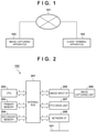
- FIG. 1 is a block diagram illustrating a configuration example of a system
- FIG. 2 is a block diagram illustrating a hardware configuration example of an image capturing apparatus 102 ;
- FIG. 3 illustrates a computer program in a primary memory 203 and data in a secondary memory 204 ;
- FIG. 4 is a flowchart of a process performed by the image capturing apparatus 102 ;
- FIG. 5 illustrates an example of displaying a list on a client terminal apparatus 103 ;
- FIG. 6 is a flowchart of a process performed by the image capturing apparatus 102 ;
- FIG. 7 is a flowchart of a process performed by the image capturing apparatus 102 ;
- FIG. 8 is a flowchart of a process performed by the image capturing apparatus 102 .
- FIG. 9 is a block diagram illustrating a hardware configuration example of the client terminal apparatus 103 .
- the system according to the present embodiment includes an image capturing apparatus 102 and a client terminal apparatus 103 , the image capturing apparatus 102 and the client terminal apparatus 103 being connected to a network 101 .
- the image capturing apparatus 102 may be an image capturing apparatus that captures motion images, or may be an image capturing apparatus that captures static images regularly or irregularly. In the former case, the image capturing apparatus 102 transmits (distributes), as captured images, images of respective frames forming the motion image to the client terminal apparatus 103 via the network 101 . On the other hand, in the latter case, the image capturing apparatus 102 transmits (distributes), as captured images, respective static images captured regularly or irregularly to the client terminal apparatus 103 via the network 101 . The image capturing apparatus 102 performs processes in accordance with various requests from the client terminal apparatus 103 .
- the hardware configuration example of the image capturing apparatus 102 will be described, referring to the block diagram of FIG. 2 .
- a CPU 202 performs various processes using computer programs and data stored in a primary memory 203 .
- the CPU 202 thus controls the overall operation of the image capturing apparatus 102 , and also performs or controls respective processes described below with the assumption to be performed by the image capturing apparatus 102 .
- the primary memory 203 is a high-speed, read and writable storage device represented by a RAM.
- the primary memory 203 has an area for storing computer programs (OS (operating system) and various computer programs described below) or data loaded from the secondary memory 204 .
- the primary memory 203 has an area for storing captured images received from an image capturing unit 206 via an image input I/F (interface) 205 , and various information received from the client terminal apparatus 103 via a network I/F 208 .
- the primary memory 203 has a work area used when the CPU 202 performs various processes. The primary memory 203 can thus provide various areas as appropriate.
- the secondary memory 204 which is a non-volatile storage device represented by an HDD (hard disk drive), a flash memory, an SD card, or the like, may be configured to be removable.
- the secondary memory 204 has stored therein the OS, various computer programs described below, and various data described below.
- the computer programs and data stored in the secondary memory 204 include computer programs and data for causing the CPU 202 to perform or control respective processes described below with the assumption to be performed by the image capturing apparatus 102 .
- the captured images received from the image capturing unit 206 via the image input I/F (interface) 205 and the various information received from the client terminal apparatus 103 via the network I/F 208 may be stored in the secondary memory 204 .
- the computer programs and data stored in the secondary memory 204 are loaded on the primary memory 203 as appropriate in accordance with the control of the CPU 202 , and subject to processing by the CPU 202 .
- the image input I/F 205 is an interface for connecting the image capturing unit 206 .
- the images captured by the image capturing unit 206 (images of respective frames in a motion image, static images captured regularly or irregularly) are transmitted to the primary memory 203 and the secondary memory 204 via the image input I/F 205 .
- the images captured by the image capturing unit 206 may also be transmitted to the client terminal apparatus 103 via the network I/F 208 .
- a PTZ drive unit 207 controls a motor (not illustrated) or the like to control P (pan), T (tilt), Z (zoom) of the image capturing apparatus 102 .
- the PTZ drive unit 207 may conduct not only PTZ control but also other settings or control in the image capturing apparatus 102 such as focus or white balance.
- the network I/F 208 is an interface for connecting the image capturing apparatus 102 to the network 101 .
- the image capturing apparatus 102 performs data communication with the client terminal apparatus 103 via the network I/F 208 .
- the CPU 202 , the primary memory 203 , the secondary memory 204 , the image input I/F 205 , the PTZ drive unit 207 , and the network I/F 208 are all connected to the internal bus 201 .
- FIG. 1 displays a configuration of a system in which a single client terminal apparatus 103 and a single image capturing apparatus 102 are connected to the network 101 .
- the number of the image capturing apparatuses 102 and the client terminal apparatus 103 connected to the network 101 is not limited to one and may be more than one.
- the client terminal apparatus 103 is a computer apparatus (information processing apparatus) such as a PC (personal computer), a tablet terminal apparatus, a smart phone, or the like.
- the hardware configuration example of the client terminal apparatus 103 will be described, referring to the block diagram of FIG. 9 .
- a CPU 901 performs various processes using computer programs and data stored in a RAM 902 or a ROM 903 . Therefore, the CPU 901 controls the overall operation of the client terminal apparatus 103 , and also performs or controls respective processes described below with the assumption to be performed by the client terminal apparatus 103 .
- the RAM 902 has an area for storing computer programs or data loaded from the ROM 903 or an external storage device 906 , or data received from the image capturing apparatus 102 via an I/F 907 .
- the RAM 902 also has a work area used when the CPU 901 performs various processes.
- the RAM 902 can thus provide various areas as appropriate.
- the ROM 903 has stored therein setting data, an activation program, or the like for the client terminal apparatus 103 .
- An operation unit 904 is a user interface such as a keyboard, a mouse, a touch panel screen, or the like, which may be operated by the user to input various instructions to the CPU 901 .
- a display unit 905 having a liquid crystal screen or a touch panel screen, can display results of processing by the CPU 901 via images, characters, or the like.
- the display unit 905 may be a projection device such as a projector that projects images or characters.
- the operation unit 904 and the display unit 905 may be integrated to form a touch panel screen.
- the external storage device 906 is a large-capacity information storage device represented by a hard disk drive or a flash memory.
- the external storage device 906 has stored therein computer programs and data for causing the CPU 901 to perform or control respective processes described below with the assumption to be performed by the client terminal apparatus 103 .
- the computer programs and data stored in the external storage device 906 are loaded to the RAM 902 as appropriate in accordance with the control of the CPU 901 , so as to be processed by the CPU 901 .
- the I/F 907 is intended to connect the client terminal apparatus 103 to the network 101 , and the client terminal apparatus 103 performs data communication with the image capturing apparatus 102 via the I/F 907 .
- the CPU 901 , the RAM 902 , the ROM 903 , the operation unit 904 , the display unit 905 , the external storage device 906 , and the I/F 907 are all connected to the bus 908 .
- the hardware configuration applicable to the client terminal apparatus 103 is not limited to the configuration illustrated in FIG. 9 .
- the network 101 is realized by a plurality of routers, switches, cables, or the like complying with a communication standard such as the ETHERNET (registered trademark), for example.
- the network 101 may be realized by the Internet, wired LAN (Local Area Network), wireless LAN, WAN (Wide Area Network), or the like.
- An OS 301 is a basic program for controlling the entire image capturing apparatus 102 .
- location (address) and size of respective programs ( 302 to 307 ) described below in the primary memory 203 is managed by the OS 301 .
- An image capturing program 302 is a computer program for implementing the image capturing function of the image capturing apparatus 102 .
- the image capturing program 302 performs an operation of acquiring a captured image from the image capturing unit 206 in accordance with an image acquisition request received from the client terminal apparatus 103 or an instruction from another computer program.
- the image capturing program 302 converts the acquired captured image into an image of the JPEG format or the like, or into a motion image of the H.264 format or the like.
- An operation state control program 303 manages the operation state of the image capturing apparatus 102 .
- the operation state of the image capturing apparatus 102 includes two types: activation state and standby state.
- the activation state is a state in which all the functions in the image capturing apparatus 102 are active
- the standby state is a state in which some of the image capturing functions are deactivated despite that the image capturing apparatus 102 is being powered.
- the standby state in the present embodiment is a state in which at least the image capturing function is deactivated.
- the operation state control program 303 upon receiving from the client terminal apparatus 103 a transition request to the standby state, deactivates the image capturing program 302 so as to deactivate the image capturing function.
- the operation state control program 303 upon receiving from the client terminal apparatus 103 a transition request to the standby state, causes a PTZ control program 304 to move the PTZ of the image capturing apparatus 102 to its home position.
- the operation state control program 303 upon receiving from the client terminal apparatus 103 a transition request to the activation state, activates the image capturing program 302 to activate the image capturing function.
- the function to be activated in response to receiving from the client terminal apparatus 103 a transition request to the activation state is a function deactivated when transitioning to the standby state.
- the operation state control program 303 upon transitioning of the operation state of the image capturing apparatus 102 (from activation state to standby state or from standby state to activation state), stores information indicating the post-transition operation state in the secondary memory 204 as camera operation state information 309 .
- the PTZ Control program 304 is a control program for driving and controlling the PTZ drive unit 207 to change the PTZ of the image capturing apparatus 102 .
- a home position setting program 305 is a program for setting a home position.
- a home position is an initial PTZ (selling value) of the image capturing apparatus 102 (image capturing unit 206 ) when the operation state of the image capturing apparatus 102 transitions from the standby state to the activation state.
- the user operates the operation unit 904 at the client terminal apparatus 103 to set a home position or change an already set home position, the set or changed home position is transmitted to the image capturing apparatus 102 via the network 101 .
- the home position setting program 305 receives the home position transmitted from e client terminal apparatus 103 and stores the received home position in the secondary memory 204 as home position information 308 .
- the home position includes only the initial PTZ, this is not limiting and any information may be included provided that it defines the initial state of the image capturing apparatus 102 (image capturing unit 206 ) when the operation state of the image capturing apparatus 102 transitions from the standby state to the activation state.
- the home position may include other setting information such as a value of focus or white balance of the image capturing unit 206 .
- An image storing program 306 upon receiving from the client terminal apparatus 103 a transition request to the standby state, acquires one of captured images from the image capturing program 302 , and stores the acquired captured image in the secondary memory 204 as image data 310 . Note that, in a case where the image data 310 is already stored in the secondary memory 204 , the image storing program 306 overwrites the one of captured images acquired from the image capturing program 302 on the image data 310 .
- the image storing program 306 performs such a storage control of images.
- the one of captured images to be acquired from the image capturing program 302 may be any image provided that it is captured before transitioning to the standby state. For example, the image may be one that has been recently captured before transitioning to the standby state, or one that has been captured within a defined time period before transitioning to the standby state.
- a request reception program 307 is a program for receiving various requests (image acquisition request, transition request, or the like) transmitted from the client terminal apparatus 103 .
- the request transmitted from the client terminal apparatus 103 may be transmitted using a general communication protocol such as http (Hypertext Transfer Protocol).
- the request receive program 307 receives, from the client terminal apparatus 103 , a transition request to the standby state.
- the request receive program 307 inquires to the operation state control program 303 whether the current operation state of the image capturing apparatus 102 is in the activation state or the standby state.
- the operation state control program 303 returns, to the request reception program 307 , the current operation state of the image capturing apparatus 102 indicated by the camera operation state information 309 stored in the secondary memory 204 .
- the request reception program 307 instructs the operation state control program 303 to transition to the standby state in a case where the operation state of the image capturing apparatus 102 returned from the operation state control program 303 is in the activation state.
- the process then proceeds to step S 403 .
- the request reception program 307 does nothing and terminates the process described in the flowchart of FIG. 4 , in a case where the operation state of the image capturing apparatus 102 returned from the operation state control program 303 is in the standby state.
- the operation state control program 303 instructs the PTZ, control program 304 to perform a PTZ control to return to the home position.
- the PTZ control program 304 reads the home position information 308 stored in the secondary memory 204 , and performs a PTZ control to move the PTZ of the image capturing apparatus 102 to the initial PTZ indicated by the read-in home position information 308 .
- the operation state control program 303 issues an instruction to the image storing program 306 to acquire and store the most recent image.
- the image storing program 306 acquires one of captured images from the image capturing program 302 , and stores (overwrites) the acquired captured image in the secondary memory 204 as the image data 310 .
- the captured image to be stored may be stored after being subjected to rendering as appropriate.
- the one of captured images acquired from the image capturing program 302 may be subjected to image processing or processes such as character superimposition so as to be distinguished from live-distributed images.
- resolution, image format, or the like may be changed when storing the captured image.
- the operation state control program 303 deactivates the image capturing program 302 to deactivate the image capturing function and transition to the standby state.
- steps S 405 other processes may be performed at step S 405 , in addition to deactivating the image capturing function.
- processes may be performed such as moving the PTZ position to a standby-state position, or providing a reception limit with regard to requests for changing the setting of the image capturing apparatus 102 by the request reception program 307 besides image acquisition requests or transition requests to the activation state.
- the operation state control program 303 then updates the camera operation state information 309 stored in the secondary memory 204 to information indicating that the current operation state of the image capturing apparatus 102 is in the standby state.
- the request reception program 307 acquires the image acquisition request transmitted from the client terminal apparatus 103 .
- the request receive program 307 inquires to the operation state control program 303 whether the current operation state of the image capturing apparatus 102 is in the activation state or the standby state.
- the operation state control program 303 returns, to the request reception program 307 , the current operation state of the image capturing apparatus 102 indicated by the camera operation state information 309 stored in the secondary memory 204 .
- step S 603 the process proceeds to step S 604 in a case where the operation state of the image capturing apparatus 102 is in the standby state.
- the request reception program 307 acquires the captured image from the image capturing program 302 as a live video.
- the request reception program 307 acquires the image data 310 stored in the secondary memory 204 .
- the request reception program 307 transmits (distributes) the live video acquired at step S 603 or the image data 310 acquired at step S 604 to the client terminal apparatus 103 via the network I/F 208 .
- FIG. 5 illustrates an example of displaying a list of information received from the image capturing apparatus 102 in response to transmitting, by the client terminal apparatus 103 , the image acquisition request to each of the four image capturing apparatuses 102 , in a case where four image capturing apparatuses 102 are connected to the network I/F 208 .
- Captured images 501 and 502 are captured images (live video) received from the image capturing apparatus 102 in the activation state.
- each of the image capturing apparatuses 102 is transmitting not only the captured images but also the camera operation state information 309 to the client terminal apparatus 103 .
- there is displayed a mark 505 on the left side of the captured image 501 indicating that the captured image 501 has been received from the image capturing apparatus 102 in the activation state.
- there is displayed a mark 506 on the left side of the captured image 502 indicating that the captured image 502 has been received from the image capturing apparatus 102 in the activation state.
- Captured images 503 and 504 are captured images (image data 310 ) received from the image capturing apparatus 102 in the standby state. There is displayed a mark 507 on the left side of the captured image 503 , indicating that the captured image 503 has been received from the image capturing apparatus 102 in the standby state. There is displayed a mark 508 on the left side of the captured image 504 , indicating that the captured image 504 has been received from the image capturing apparatus 102 in the standby state. In FIG.
- the marks 505 and 506 indicating that the captured images are received from the image capturing apparatus 102 in the activation state are displayed with a darker color than the marks 507 and 508 indicating that the captured images are received from the image capturing apparatus 102 in the standby state. Note that it suffices to display (control display of) the marks corresponding to captured images received from the image capturing apparatus 102 in the activation state and the marks corresponding to captured images received from the image capturing apparatus 102 in the standby state as marks distinguishable from each other, with the display method not being limited to any specific display method.
- the client terminal apparatus 103 Upon the user's pointing the mark 507 (the user may point using the operation unit 904 , or tap the mark 507 on the display screen), the client terminal apparatus 103 transmits, to the image capturing apparatus 102 that has captured the captured image 503 , a transition request to the activation state.
- the client terminal apparatus 103 transmits, to the image capturing apparatus 102 that has captured the captured image 504 , a transition request to the activation state.
- a captured image may be pointed instead of a mark.
- the method of displaying a captured image as it is may be changed according to whether the captured image has been received from the image capturing apparatus 102 in the standby state, or from the image capturing apparatus 102 in the activation state.
- the captured images 503 and 504 received from the image capturing apparatus 102 in the standby state are displayed darker than the captured images 501 and 502 received from the image capturing apparatus 102 in the activation state.
- images whose image capturing direction at the time of activating the image capturing apparatus is known can be acquired also from the image capturing apparatus in the standby state, and therefore it becomes easier for a user to select an image capturing apparatus that the user desires to activate from a list of image capturing apparatuses, thereby improving the convenience.
- the image capturing apparatus 102 in the activation state performs a process according to the flowchart illustrated in FIG. 7 .
- the image storing program 306 starts clocking (starts time measurement).
- the image storing program 306 determines whether or not the time being clocked has exceeded a predetermined time (predetermined time)
- the predetermined time may be a time period such as 30 minutes, for example, which is a default setting in the image capturing apparatus 102 , a time period preliminarily set by the user in the image capturing apparatus 102 or the client terminal apparatus 103 , or elapsed time acquired at step S 706 described below.
- step S 704 the process proceeds to step S 703 when the time being clocked has fallen below the predetermined time.
- the PTZ control program 304 determines whether or not a change in PTZ (change in at least one of P, and Z) has been detected.
- a change in PTZ change in at least one of P, and Z
- the process proceeds to step S 701 , or the process proceeds to step S 702 when no change in PTZ has been detected.
- the image storing program 306 acquires one of captured images from the image capturing program 302 , and stores (overwrites) the acquired captured image in the secondary memory 204 as the image data 310 .
- the captured image to be stored may be stored after being subjected to rendering as appropriate.
- the one of captured images acquired from the image capturing program 302 may be subjected to image processing or processes such as character superimposition so as to be distinguished from live-distributed images.
- resolution, image format, or the like may be changed when storing the captured image.
- step S 705 it is determined whether or not a change in PTZ (change in at least one of P, T and Z) has been detected at or subsequent to step S 701 .
- a change in PTZ change in at least one of P, T and Z
- the configuration for “detecting a change in PTZ” is not limited to a specific configuration.
- step S 701 When, as a result of such a determination, a change in PTZ has been detected at or subsequent to step S 701 , the process proceeds to step S 706 , or the process proceeds to step S 705 when no change in PTZ has been detected at or subsequent to step S 701 .
- the image storing program 306 stores the time clocked up to now (time passed since the start of measurement to the current time point) in the secondary memory 204 as elapsed time.
- the elapsed time stored here may be used as the predetermined time described above.
- the form of storing the elapsed time is not limited to a specific storage form, and the elapsed time may be stored as header data of the image data 310 , for example, or may be stored as text data separate from the image data 310 .
- the process then proceeds to step S 701 .
- elapsed time is counted each time PTZ control is performed even when the image capturing apparatus 102 is the activation state, and the image data 310 stored in the secondary memory 204 is updated when a predetermined time has elapsed. Accordingly, the client terminal apparatus 103 can acquire and display an image at a location where the image capturing apparatus 102 has been performing image capturing for the longest time, as a captured image acquired in response to an image acquisition request from the image capturing apparatus 102 in the standby state. Accordingly, the convenience when the user is selecting from the list of image capturing apparatuses increases.
- the present embodiment controls whether or not to overwrite the captured image acquired from the image capturing program 302 by the image storing program 306 over the image data 310 already stored in the secondary memory 204 .
- a process for controlling whether or not to overwrite, by the image storing program 306 , the captured image acquired from the image capturing program 302 over the image data 310 previously stored in the secondary memory 204 will be described in accordance with the flowchart of FIG. 8 .
- the image storing program 306 determines whether or not the image data 310 has already been stored in the secondary memory 204 .
- the process proceeds to step S 802 , or the process proceeds to step S 803 when the image data 310 has not yet been stored in the secondary memory 204 .
- the image storing program 306 acquires the image data 310 already stored in the secondary memory 204 .
- the image storing program 306 acquires one of captured images from the image capturing program 302 .
- the operation of the image storing program 306 at step S 804 is different for when the image storing program 306 performs the process of step S 802 and for when the image storing program 306 is not performing the process of step S 802 .
- the image storing program 306 determines which of the “image data 310 ” acquired at step S 802 or the “captured image” acquired at step S 803 is to be stored in the secondary memory 204 as a new version of the image data 310 .
- the method for determining an image to be stored in the secondary memory 204 as a new version of the image data 310 is not limited to a specific method.
- the image to be stored in the secondary memory 204 as a new version of the image data 310 may be determined by comparing histograms of luminance values of respective images and selecting an image with less blown-out highlights or shadow detail loss.
- a better-focused image may be determined as the image to be stored in the secondary memory 204 as a new version of the image data 310 .
- the image to be stored in the secondary memory 204 may be determined as a new version of the image data 310 on the basis of image information of respective images.
- the image storing program 306 then does nothing when having determined to store the “image data 310 ” acquired at step S 802 in the secondary memory 204 as a new version of the image data 310 .
- the image storing program 306 stores (overwrites) the “captured image” in the secondary memory 204 as the image data 310 .
- the image storing program 306 stores (overwrites) the “captured image” acquired at step S 803 in the secondary memory 204 as a new version of the image data 310 .
- deactivation of the image capturing function is not limited to deactivate acquisition of captured images by the image capturing unit 206 .
- the power being supplied to the image capturing unit 206 may be reduced to be lower than the power supplied in the activation state.
- a part or all of the aforementioned embodiments may be used in combination as appropriate.
- a part or all of the aforementioned embodiments may be selectively used.
- Embodiment(s) of the present invention can also be realized by a computer of a system or apparatus that reads out and executes computer executable instructions (e.g., one or more programs) recorded on a storage medium (which may also be referred to more fully as a ‘non-transitory computer-readable storage medium’) to perform the functions of one or more of the above-described embodiment(s) and/or that includes one or more circuits (e.g., application specific integrated circuit (ASIC)) for performing the functions of one or more of the above-described embodiment(s), and by a method performed by the computer of the system or apparatus by, for example, reading out and executing the computer executable instructions from the storage medium to perform the functions of one or more of the above-described embodiment(s) and/or controlling the one or more circuits to perform the functions of one or more of the above-described embodiment(s).
- computer executable instructions e.g., one or more programs
- a storage medium which may also be referred to more fully as a
- the computer may comprise one or more processors (e.g., central processing unit (CPU), micro processing unit (MPU)) and may include a network of separate computers or separate processors to read out and execute the computer executable instructions.
- the computer executable instructions may be provided to the computer, for example, from a network or the storage medium.
- the storage medium may include, for example, one or more of a hard disk, a random-access memory (RAM), a read only memory (ROM), a storage of distributed computing systems, an optical disk (such as a compact disc (CD), digital versatile disc (DVD), or Blu-ray Disc (BD)TM), a flash memory device, a memory card, and the like.
Landscapes
- Engineering & Computer Science (AREA)
- Multimedia (AREA)
- Signal Processing (AREA)
- Studio Devices (AREA)
- Details Of Cameras Including Film Mechanisms (AREA)
- Indication In Cameras, And Counting Of Exposures (AREA)
- Accessories Of Cameras (AREA)
- Closed-Circuit Television Systems (AREA)
Applications Claiming Priority (3)
| Application Number | Priority Date | Filing Date | Title |
|---|---|---|---|
| JP2019-044193 | 2019-03-11 | ||
| JP2019044193A JP7284600B2 (ja) | 2019-03-11 | 2019-03-11 | 撮像装置、撮像装置の制御方法、情報処理装置、情報処理装置の制御方法 |
| JPJP2019-044193 | 2019-03-11 |
Publications (2)
| Publication Number | Publication Date |
|---|---|
| US20200296297A1 US20200296297A1 (en) | 2020-09-17 |
| US11272102B2 true US11272102B2 (en) | 2022-03-08 |
Family
ID=72422812
Family Applications (1)
| Application Number | Title | Priority Date | Filing Date |
|---|---|---|---|
| US16/813,007 Active US11272102B2 (en) | 2019-03-11 | 2020-03-09 | Image capturing apparatus, control method of image capturing apparatus, and control method of information processing apparatus |
Country Status (2)
| Country | Link |
|---|---|
| US (1) | US11272102B2 (enExample) |
| JP (1) | JP7284600B2 (enExample) |
Families Citing this family (1)
| Publication number | Priority date | Publication date | Assignee | Title |
|---|---|---|---|---|
| JP2022175637A (ja) * | 2021-05-14 | 2022-11-25 | キヤノン株式会社 | 撮像装置、撮像方法、及びコンピュータプログラム |
Citations (3)
| Publication number | Priority date | Publication date | Assignee | Title |
|---|---|---|---|---|
| JP2004328271A (ja) | 2003-04-23 | 2004-11-18 | Canon Inc | 撮像装置及びそのデータ送信制御方法 |
| US20110157460A1 (en) * | 2009-12-30 | 2011-06-30 | Samsung Electronics Co., Ltd. | Method and apparatus for driving camera |
| US20140184824A1 (en) * | 2012-12-28 | 2014-07-03 | Canon Kabushiki Kaisha | Communication apparatus and method of controlling communication apparatus |
Family Cites Families (3)
| Publication number | Priority date | Publication date | Assignee | Title |
|---|---|---|---|---|
| JP4244539B2 (ja) | 2001-08-03 | 2009-03-25 | 富士フイルム株式会社 | カメラの遠隔制御方法及びカメラシステム |
| JP4667246B2 (ja) | 2006-01-06 | 2011-04-06 | キヤノン株式会社 | 撮像装置及び画像データの制御方法 |
| JP6436948B2 (ja) | 2016-08-30 | 2018-12-12 | キヤノン株式会社 | 通信装置、通信装置の制御方法、プログラム |
-
2019
- 2019-03-11 JP JP2019044193A patent/JP7284600B2/ja active Active
-
2020
- 2020-03-09 US US16/813,007 patent/US11272102B2/en active Active
Patent Citations (3)
| Publication number | Priority date | Publication date | Assignee | Title |
|---|---|---|---|---|
| JP2004328271A (ja) | 2003-04-23 | 2004-11-18 | Canon Inc | 撮像装置及びそのデータ送信制御方法 |
| US20110157460A1 (en) * | 2009-12-30 | 2011-06-30 | Samsung Electronics Co., Ltd. | Method and apparatus for driving camera |
| US20140184824A1 (en) * | 2012-12-28 | 2014-07-03 | Canon Kabushiki Kaisha | Communication apparatus and method of controlling communication apparatus |
Also Published As
| Publication number | Publication date |
|---|---|
| JP2020150332A (ja) | 2020-09-17 |
| US20200296297A1 (en) | 2020-09-17 |
| JP7284600B2 (ja) | 2023-05-31 |
Similar Documents
| Publication | Publication Date | Title |
|---|---|---|
| US9967473B2 (en) | Information processing apparatus, information processing method, and program | |
| US11172136B2 (en) | Image capturing apparatus, control apparatus, storage medium, and control method | |
| US20150116489A1 (en) | Imaging apparatus | |
| US10063734B2 (en) | Information processing apparatus that receives data from external apparatus via network, method of controlling the same, and storage medium | |
| US11711607B2 (en) | Information processing apparatus capable of applying image processing based on evaluation results, image processing apparatus, and method of controlling the same | |
| US10771732B2 (en) | System, imaging apparatus, information processing apparatus, and recording medium | |
| US11272102B2 (en) | Image capturing apparatus, control method of image capturing apparatus, and control method of information processing apparatus | |
| JP6980450B2 (ja) | 制御装置、制御方法、及びプログラム | |
| US10567634B2 (en) | Image capturing apparatus, communication apparatus, and control methods thereof | |
| EP2811732B1 (en) | Image processing apparatus, image processing method, computer-readable storage medium and program | |
| US10349002B2 (en) | Image recording apparatus and method for controlling the same | |
| US20200177803A1 (en) | Imaging apparatus, control method, and program | |
| CN107295247B (zh) | 图像记录装置及其控制方法 | |
| US11064103B2 (en) | Video image transmission apparatus, information processing apparatus, system, information processing method, and recording medium | |
| US20060059202A1 (en) | Image capture device | |
| JP2017228897A (ja) | 通信装置、撮像装置、それらの制御方法、プログラム及び記録媒体 | |
| US12542865B2 (en) | Communication device and control device | |
| US20120327253A1 (en) | Image capturing transfer apparatus that sends a flash on/off parameter instruction for a flash unit connected to the image capturing apparatus | |
| US11943528B2 (en) | Information processing apparatus, information processing method, and program | |
| US20250203226A1 (en) | Electronic device and imaging apparatus | |
| US11831978B2 (en) | Recording apparatus, control method thereof, and storage medium | |
| US11528415B2 (en) | Imaging apparatus, method of controlling imaging apparatus, and storage medium | |
| US20240365001A1 (en) | Image capture apparatus and method of controlling image capture apparatus, and non-transitory computer-readable medium | |
| US10372404B2 (en) | Data processing apparatus, data processing method, and non-transitory computer readable medium | |
| US20210258469A1 (en) | Image processing apparatus, image processing system, and control method for the same |
Legal Events
| Date | Code | Title | Description |
|---|---|---|---|
| FEPP | Fee payment procedure |
Free format text: ENTITY STATUS SET TO UNDISCOUNTED (ORIGINAL EVENT CODE: BIG.); ENTITY STATUS OF PATENT OWNER: LARGE ENTITY |
|
| AS | Assignment |
Owner name: CANON KABUSHIKI KAISHA, JAPAN Free format text: ASSIGNMENT OF ASSIGNORS INTEREST;ASSIGNOR:YANAGISAWA, TAKAFUMI;REEL/FRAME:053105/0301 Effective date: 20200214 |
|
| STPP | Information on status: patent application and granting procedure in general |
Free format text: DOCKETED NEW CASE - READY FOR EXAMINATION |
|
| STPP | Information on status: patent application and granting procedure in general |
Free format text: NON FINAL ACTION MAILED |
|
| STPP | Information on status: patent application and granting procedure in general |
Free format text: NOTICE OF ALLOWANCE MAILED -- APPLICATION RECEIVED IN OFFICE OF PUBLICATIONS |
|
| STPP | Information on status: patent application and granting procedure in general |
Free format text: DOCKETED NEW CASE - READY FOR EXAMINATION |
|
| STPP | Information on status: patent application and granting procedure in general |
Free format text: NOTICE OF ALLOWANCE MAILED -- APPLICATION RECEIVED IN OFFICE OF PUBLICATIONS |
|
| STCF | Information on status: patent grant |
Free format text: PATENTED CASE |
|
| MAFP | Maintenance fee payment |
Free format text: PAYMENT OF MAINTENANCE FEE, 4TH YEAR, LARGE ENTITY (ORIGINAL EVENT CODE: M1551); ENTITY STATUS OF PATENT OWNER: LARGE ENTITY Year of fee payment: 4 |