US11234297B2 - Plate heater - Google Patents
Plate heater Download PDFInfo
- Publication number
- US11234297B2 US11234297B2 US16/170,876 US201816170876A US11234297B2 US 11234297 B2 US11234297 B2 US 11234297B2 US 201816170876 A US201816170876 A US 201816170876A US 11234297 B2 US11234297 B2 US 11234297B2
- Authority
- US
- United States
- Prior art keywords
- electrode
- electrodes
- branch electrodes
- branch
- power input
- Prior art date
- Legal status (The legal status is an assumption and is not a legal conclusion. Google has not performed a legal analysis and makes no representation as to the accuracy of the status listed.)
- Active, expires
Links
Images


Classifications
-
- H—ELECTRICITY
- H05—ELECTRIC TECHNIQUES NOT OTHERWISE PROVIDED FOR
- H05B—ELECTRIC HEATING; ELECTRIC LIGHT SOURCES NOT OTHERWISE PROVIDED FOR; CIRCUIT ARRANGEMENTS FOR ELECTRIC LIGHT SOURCES, IN GENERAL
- H05B3/00—Ohmic-resistance heating
- H05B3/84—Heating arrangements specially adapted for transparent or reflecting areas, e.g. for demisting or de-icing windows, mirrors or vehicle windshields
-
- H—ELECTRICITY
- H05—ELECTRIC TECHNIQUES NOT OTHERWISE PROVIDED FOR
- H05B—ELECTRIC HEATING; ELECTRIC LIGHT SOURCES NOT OTHERWISE PROVIDED FOR; CIRCUIT ARRANGEMENTS FOR ELECTRIC LIGHT SOURCES, IN GENERAL
- H05B3/00—Ohmic-resistance heating
- H05B3/02—Details
- H05B3/03—Electrodes
-
- H—ELECTRICITY
- H05—ELECTRIC TECHNIQUES NOT OTHERWISE PROVIDED FOR
- H05B—ELECTRIC HEATING; ELECTRIC LIGHT SOURCES NOT OTHERWISE PROVIDED FOR; CIRCUIT ARRANGEMENTS FOR ELECTRIC LIGHT SOURCES, IN GENERAL
- H05B3/00—Ohmic-resistance heating
- H05B3/10—Heating elements characterised by the composition or nature of the materials or by the arrangement of the conductor
- H05B3/12—Heating elements characterised by the composition or nature of the materials or by the arrangement of the conductor characterised by the composition or nature of the conductive material
- H05B3/14—Heating elements characterised by the composition or nature of the materials or by the arrangement of the conductor characterised by the composition or nature of the conductive material the material being non-metallic
- H05B3/145—Carbon only, e.g. carbon black, graphite
-
- H—ELECTRICITY
- H05—ELECTRIC TECHNIQUES NOT OTHERWISE PROVIDED FOR
- H05B—ELECTRIC HEATING; ELECTRIC LIGHT SOURCES NOT OTHERWISE PROVIDED FOR; CIRCUIT ARRANGEMENTS FOR ELECTRIC LIGHT SOURCES, IN GENERAL
- H05B3/00—Ohmic-resistance heating
- H05B3/10—Heating elements characterised by the composition or nature of the materials or by the arrangement of the conductor
- H05B3/16—Heating elements characterised by the composition or nature of the materials or by the arrangement of the conductor the conductor being mounted on an insulating base
-
- H—ELECTRICITY
- H05—ELECTRIC TECHNIQUES NOT OTHERWISE PROVIDED FOR
- H05B—ELECTRIC HEATING; ELECTRIC LIGHT SOURCES NOT OTHERWISE PROVIDED FOR; CIRCUIT ARRANGEMENTS FOR ELECTRIC LIGHT SOURCES, IN GENERAL
- H05B3/00—Ohmic-resistance heating
- H05B3/20—Heating elements having extended surface area substantially in a two-dimensional plane, e.g. plate-heater
- H05B3/22—Heating elements having extended surface area substantially in a two-dimensional plane, e.g. plate-heater non-flexible
- H05B3/26—Heating elements having extended surface area substantially in a two-dimensional plane, e.g. plate-heater non-flexible heating conductor mounted on insulating base
-
- H—ELECTRICITY
- H05—ELECTRIC TECHNIQUES NOT OTHERWISE PROVIDED FOR
- H05B—ELECTRIC HEATING; ELECTRIC LIGHT SOURCES NOT OTHERWISE PROVIDED FOR; CIRCUIT ARRANGEMENTS FOR ELECTRIC LIGHT SOURCES, IN GENERAL
- H05B2203/00—Aspects relating to Ohmic resistive heating covered by group H05B3/00
- H05B2203/002—Heaters using a particular layout for the resistive material or resistive elements
- H05B2203/006—Heaters using a particular layout for the resistive material or resistive elements using interdigitated electrodes
-
- H—ELECTRICITY
- H05—ELECTRIC TECHNIQUES NOT OTHERWISE PROVIDED FOR
- H05B—ELECTRIC HEATING; ELECTRIC LIGHT SOURCES NOT OTHERWISE PROVIDED FOR; CIRCUIT ARRANGEMENTS FOR ELECTRIC LIGHT SOURCES, IN GENERAL
- H05B2214/00—Aspects relating to resistive heating, induction heating and heating using microwaves, covered by groups H05B3/00, H05B6/00
- H05B2214/04—Heating means manufactured by using nanotechnology
Definitions
- the present invention relates to a plane heater in which graphene or the like is used as the conductive heat generation material thereof.
- plane heaters may be applied to the glass surfaces of freezing display cases, window systems, the glass surfaces or sheets of automobiles, the mirrors of bathrooms, electric rice cookers, etc.
- Such a plane heater is generally configured such that a conductive heat generation material, such as graphene or the like, is applied to a nonconductive substrate and, for example, a first electrode, i.e., a positive electrode, and a second electrode, i.e., a negative electrode, are coupled to the conductive heat generation material. Then, when a direct or alternating current voltage is applied to the first electrode and the second electrode, current flows across the conductive heating material and thus resistance heat is generated.
- a conductive heat generation material such as graphene or the like
- the present invention has been conceived to overcome the above-described problems of the prior art, and an object of the present invention is to provide technology that enables resistance to be uniform throughout all electric circuits including both electrodes and heat generation material.
- a plane heater including: a nonconductor substrate; a heat generation material applied to the nonconductor substrate; and a pair of electrodes configured to generate resistance heat in the heat generation material; wherein the pair of electrodes include: a first electrode configured to be connected to one pole of a power source; and a second electrode configured to be connected to the other pole of the power source; and wherein the sectional areas of at least some portions of the first electrode and the second electrode are determined such that a plurality of electric circuits formed by the first electrode, the heat generation material, and the second electrode can have the theoretically same resistance.
- the first electrode may include first branch electrodes branched off from the first primary electrode; the second electrode may include second branch electrodes branched off from the second primary electrode; and the first primary electrode and the second primary electrode may be disposed opposite to each other, and the sectional areas of the branch electrodes may be made different from each other such that the plurality of electric circuits can have the theoretically same resistance.
- the sectional areas of the branch electrodes may be increased in proportion to their distances from power input points at which power is input to the first electrode and the second electrode.
- the branch electrodes may be each divided into two twig electrodes; each adjacent two of the twig electrodes having different poles may have the same sectional area; and, of the twig electrodes constituting each of the branch electrodes, the twig electrode farther from the power source input points may have a larger sectional area than the twig electrode closer to the power source input points.
- the first or second electrode may further include a blocking electrode branched off from the first or second primary electrode in order to prevent a direct electric circuit from being formed between the first or second primary electrode and one of the branch electrodes that have opposite poles.
- the first electrode may include first branch electrodes branched off from the first primary electrode; the second electrode may include second branch electrodes branched off from the second primary electrode; and the first branch electrodes and the second branch electrodes may be provided in arc shapes, and the sectional areas of the branch electrodes may be increased in a direction from the center of a circle to the outside thereof.
- the sectional areas of at least some portions of electrodes constituting the electric circuits may be increased in proportion to the distances over which current flows in the corresponding electric circuits.
- a plane heater including: a nonconductor substrate; a heat generation material applied to the nonconductor substrate; and a pair of electrodes configured to generate resistance heat in the heat generation material; wherein the pair of electrodes include: a first electrode configured to be connected to one pole of a power source; and a second electrode configured to be connected to the other pole of the power source; and wherein the intervals between at least some portions of the first electrode and the second electrode are determined such that a plurality of electric circuits formed by the first electrode, the heat generation material, and the second electrode can have the theoretically same resistance.
- the first electrode may include first branch electrodes branched off from the first primary electrode; the second electrode may include second branch electrodes branched off from the second primary electrode; and the first primary electrode and the second primary electrode may be disposed opposite to each other, and the intervals between the branch electrodes may be made different from each other such that the plurality of electric circuits can have the theoretically same resistance.
- the intervals between the branch electrodes may be decreased in proportion to their distances from power input points at which power is input to the first electrode and the second electrode.
- the first or second electrode may further include a blocking electrode branched off from the first or second primary electrode in order to prevent a direct electric circuit from being formed between the first or second primary electrode and one of the branch electrodes that have opposite poles.
- the first electrode may include first branch electrodes branched off from the first primary electrode; the second electrode may include second branch electrodes branched off from the second primary electrode; and the first branch electrodes and the second branch electrodes may be provided in arc shapes, and the intervals between the branch electrodes may be decreased in a direction from the outside of a circle to the center thereof.
- the intervals between at least some portions of electrodes constituting the electric circuits may be decreased in proportion to distances over which current flows in the corresponding electric circuits.
- the sectional areas of at least some portions of the first electrode and the second electrode may be determined such that the plurality of electric circuits formed by the first electrode, the heat generation material, and the second electrode can have the theoretically same resistance.
- a plane heater including: a nonconductor substrate; a heat generation material applied to the nonconductor substrate; a pair of electrodes configured to generate resistance heat in the heat generation material; and a bridge configured to serve as a medium for a current flow between the pair of electrodes; wherein the pair of electrodes include: a first electrode configured to be connected to one pole of a power source; and a second electrode configured to be connected to the other pole of the power source; and wherein the bridge is disposed to serve as a medium for a current flow between the first electrode and the second electrode.
- the bridge may include a plurality of bridges, and the plurality of bridges may be disposed such that current can flow between the first electrode and the second electrode through at least two of the bridges.
- Linear cut regions formed by cutting a heat generation material layer may be provided such that current can flow between the first electrode and the second electrode through the at least two of the bridges.
- FIG. 1 shows a first embodiment of the electrodes of a plane heater according to a first aspect of the present invention
- FIG. 2 shows excerpts of two representative electric circuits that are taken from the electrodes of FIG. 1 ;
- FIG. 3 is a reference diagram illustrating a difference in width between the branch electrodes of FIG. 1 ;
- FIG. 4 shows a second embodiment of the electrodes of a plane heater according to the first aspect of the present invention
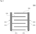
- FIG. 5 shows a third embodiment of the electrodes of a plane heater according to the first aspect of the present invention
- FIG. 6 shows a fourth embodiment of the electrodes of a plane heater according to the first aspect of the present invention.
- FIG. 7 shows a fifth embodiment of the electrodes of a plane heater according to the first aspect of the present invention.
- FIG. 8 shows a sixth embodiment of the electrodes of a plane heater according to the first aspect of the present invention.
- FIG. 9 shows a first embodiment of the electrodes of a plane heater according to a second aspect of the present invention.
- FIG. 10 shows excerpts of two representative electric circuits that are taken from the electrodes of FIG. 9 ;
- FIG. 11 is a reference diagram illustrating a difference in interval between the branch electrodes of FIG. 9 ;
- FIG. 12 shows a second embodiment of the electrodes of a plane heater according to the second aspect of the present invention.
- FIG. 13 shows a third embodiment of the electrodes of a plane heater according to the second aspect of the present invention.
- FIG. 14 illustrates the electrodes of a plane heater according to a modification of the embodiment of FIG. 13 ;
- FIG. 15 shows a fourth embodiment of the electrodes of a plane heater according to the second aspect of the present invention.
- FIG. 16 shows a fifth embodiment of the electrodes of a plane heater according to the second aspect of the present invention.
- FIG. 17 shows a first embodiment of the electrodes of a plane heater according to a third aspect of the present invention.
- FIG. 18 shows a second embodiment of the electrodes of a plane heater according to the third aspect of the present invention.
- FIG. 19 shows a third embodiment of the electrodes of a plane heater according to the third aspect of the present invention.
- FIG. 20 shows a fourth embodiment of the electrodes of a plane heater according to the third aspect of the present invention.
- FIG. 21 shows a fifth embodiment of the electrodes of a plane heater according to the third aspect of the present invention.
- heat generation material such as graphene or the like
- a nonconductor substrate For reference, in the following description of the present invention, it is assumed that heat generation material, such as graphene or the like, is uniformly applied to a nonconductor substrate. Based on this assumption, the following description will be given on a focus on the structures of arrangements of first and second electrodes, which are the characteristic parts of the present invention.
- FIG. 1 is a view illustrating an arrangement of electrodes in a plane heater 100 A that is implemented as a first embodiment according to a first aspect of the present invention.
- the plane heater 100 A includes a pair of first and second electrodes 110 A and 120 A configured to generate resistance heat in heat generation material.
- the first electrode 110 A includes a first power input point 111 A, a first primary electrode 112 A, and a plurality of first branch electrodes 113 A.
- the first power input point 111 A is connected to the + pole or ⁇ pole of a power source.
- the first primary electrode 112 A is extended in a U shape in left and right directions from the first power input point 111 A.
- the plurality of first branch electrodes 113 A is branched off from the first primary electrode 112 A, and is extended in an inward direction, i.e., a direction toward the second electrode 120 A to be described below.
- the second electrode 120 A includes a second power input point 121 A, a second primary electrode 122 A, and a plurality of second branch electrodes 123 A.
- the second power input point 121 A is connected to the pole of the power source that is opposite to the pole to which the first power input point 111 A is connected.
- the second primary electrode 122 A is spaced apart from the first primary electrode 112 A while facing the first primary electrode 112 A, and is extended in a U shape in left and right directions from the second power input point 121 A.
- the plurality of second branch electrodes 123 A is branched off from the second primary electrode 122 A, and is extended in an outward direction, i.e., a direction toward the first primary electrode 112 A.
- the first branch electrodes 113 A and the second branch electrodes 123 A are alternately arranged, and thus current can flow across the heat generation material between the first branch electrodes 113 A and the second branch electrodes 123 A.
- the first branch electrodes 113 A and the second branch electrodes 123 A are arranged in such a manner that each of the second branch electrodes 123 A is located between corresponding adjacent two of the first branch electrodes 113 A.
- the first power input point 111 A when the first power input point 111 A is connected to the + pole of the power source, current flows along a plurality of electric circuits that are connected in the sequence of the first power input point 111 A, the first primary electrode 112 A, the plurality of first branch electrodes 113 A, the heat generation material, the plurality of second branch electrodes 123 A, the second primary electrode 122 A, and the second power input point 121 A.
- current flows across the heat generation material, resistance heat is generated due to the resistance of the heat generation material.
- the present invention it is required that all the theoretically possible electric circuits connected from the first power input point 111 A to the second power input point 121 A have the same resistance. In that case, the amount of current flowing through the heat generation material between both branch electrodes 113 A and 123 A becomes the same in all areas, with the result that the same resistance heat can be generated in all areas where the heating material is present.
- FIGS. 2( a ) and 2( b ) are excerpts of two electric circuits that are taken from FIG. 1 as an example.
- FIG. 2 there are shown a first electric circuit EC 1 (see FIG. 2( a ) ) in which a first branch electrode 113 A-N and a second branch electrode 123 A-N closest to both the power input points 111 A and 121 A are included, and a second electric circuit EC 2 (see FIG. 2( b ) ) in which a first branch electrode 113 A-F and a second branch electrode 123 A-F farthest from both the power input points 111 A and 121 A are included.
- the first electric circuit EC 1 is significantly shorter than the second electric circuit EC 2 .
- resistance is known to be present not only in the heat generation material but also in both the primary electrodes 112 A and 122 A and the branch electrodes 113 A and 123 A.
- the first electric circuit EC 1 has lower resistance than the second electric circuit EC 2 when viewed only from the point of view of the lengths of the electric circuits EC 1 and EC 2 . Accordingly, it can be seen that a larger amount of current flows along the first electric circuit EC 1 and thus a larger amount of resistance heat is generated in the heat generation material between both the branch electrodes 113 A-N and 123 A-N that are present in the corresponding circuit.
- the widths W F1 and W F2 of both the branch electrodes 113 A-F and 123 A-F constituting the second electric circuit EC 2 are made larger than the widths W N1 and W N2 of both the branch electrodes 113 A-N and 123 A-N constituting the first electric circuit EC 1 , and thus the resistance of both the branch electrodes 113 A-F and 123 A-F constituting the second electric circuit EC 2 is made lower than the resistance of both the branch electrodes 113 A-N and 123 A-N constituting the first electric circuit EC 1 .
- the difference between the widths of the branch electrodes 112 A and 113 A is determined to be a value at which all the electric circuits have the same the resistances.
- the coating thickness of both the branch electrodes 113 A-F and 123 A-F constituting the second electric circuit EC 2 is ideally the same as the coating thickness of both the branch electrodes 113 A-N and 123 A-N constituting the first electric circuit EC 1 .
- the resistance in both the branch electrodes 113 A-F and 123 A-F constituting the second electric circuit EC 2 and the resistance in both the branch electrodes 113 A-N and 123 A-N constituting the first electric circuit EC 1 are made different from each other.
- the difference in the resistance is set such that the overall resistance of the first electric circuit EC 1 and the overall resistance of the second electric circuit EC 2 have the ideally same value.
- the difference in the sectional area may be set by changing the thicknesses of both the branch electrodes 113 A and 123 A or the widths and thicknesses thereof because resistance is inversely proportional to the sectional area of a conductive line.
- changing the widths is more advantageous in terms of a process than changing the thicknesses, and thus it may be preferably taken into account that the widths of the branch electrodes 113 A and 123 A are made different from each other, as in the present embodiment.
- all the electric circuits that can be theoretically taken into account are made to have the same resistance in such a manner that the widths of the branch electrodes 113 A and 123 A are decreased as the branch electrodes 113 A and 123 A become closer to the power input points 111 A and 121 A and the widths of the branch electrodes 113 A and 123 A are increased as the branch electrodes 113 A and 123 A become farther from the power input points 111 A and 121 A.
- a cut line C or uncoated region configured to block a current flow is placed on the heat generation material of a corresponding portion. It will be apparent that such a cut line C or uncoated region may be placed on any portion where an unintended current flow occurs between the branch electrode 113 A or 123 A and the primary electrode 112 A or 122 A. This is also applied to other embodiments.
- FIG. 4 is a view illustrating an arrangement of electrodes in a plane heater 200 A that is implemented as a second embodiment according to the first aspect of the present invention.
- both power input points 211 A and 221 A are off-centered to one side on a first electrode 210 A and a second electrode 220 A unlike those of the first embodiment.
- all the electric circuits that can be ultimately taken into account are made to have the same resistance in such a manner that the widths of branch electrodes 213 A and 223 A are increased as the branch electrodes 213 A and 223 A become farther from the power input points 211 A and 223 A.
- a blocking electrode 223 A-I branched off from a second primary electrode 222 A is disposed such that the second primary electrode 222 A having a portion parallel to the branch electrodes 213 A and 223 A can be prevented from being directly adjacent to a branch electrode 213 A branched off from a first primary electrode 212 A. Accordingly, an electric circuit can be prevented from being formed between a first branch electrode 213 A-N closest to the first power input point 211 A and the portion of the second primary electrode 222 A parallel to the first branch electrode 213 A-N.
- the first primary electrode may be configured to have a portion parallel to the branch electrodes depending on implementation, in which case a blocking electrode may be branched off from the first primary electrode.
- FIG. 5 is a view illustrating an arrangement of electrodes in a plane heater 300 A that is implemented as a third embodiment according to the first aspect of the present invention.
- primary electrodes 312 A and 322 A are extended from separate power input points 311 A and 321 A, respectively, in parallel to each other.
- branch electrodes 313 A and 323 A are branched off from the primary electrodes 312 A and 322 A, and are alternately arranged.
- the widths of the branch electrodes 313 A and 323 A are increased as the branch electrodes 313 A and 323 A become farther from the power input points 311 A and 321 A, in the same manner as in the previous embodiments.
- FIG. 6 is a view illustrating an arrangement of electrodes in a plane heater 400 A that is implemented as a fourth embodiment according to the first aspect of the present invention.
- the plane heater 400 A also includes: a first electrode 410 A including a first power input point 411 A, a first primary electrode 412 A, and first branch electrodes 413 A; and a second electrode 420 A including a second power input point 421 A, a second primary electrode 422 A, and second branch electrodes 423 A.
- the branch electrodes 413 A and 423 A are arranged in arc shapes. Furthermore, the first power input point 411 A and the second power input point 421 A are disposed on both corresponding sides, respectively, on a line L that passes through the center O of the outermost branch electrode 413 A-L having the largest radius. In other words, the first power input point 411 A and the second power input point 421 A are disposed as far as possible from each other.
- branch electrodes 413 A and 423 A are provided in the form of arcs having different radii, and are disposed such that opposite poles can be adjacent to each other.
- the widths of the branch electrodes 413 A and 423 A are increased in a direction from the center a circle to the outside thereof so that the widths (and/or thicknesses) of the branch electrodes 413 A and 423 A are increased in proportion to the distance over which current flows.
- a plane heater 500 A shown in FIG. 7 is configured such that both power input points 511 A and 521 A of both electrodes 510 A and 520 A are gathered together and arranged on the same side and branch electrodes 513 A and 523 A branched off from primary electrodes 512 A and 522 A are divided into both sides and formed in arc shapes, unlike that shown in FIG. 6 .
- the widths (and/or thicknesses) of the branch electrodes 513 A and 523 A are increased in a direction from the center of a circle to the outside thereof.
- FIG. 8 is a view illustrating an arrangement of electrodes in a plane heater 600 A that is implemented as a sixth embodiment according to the first aspect of the present invention.
- the plane heater 600 A includes a pair of first and second electrodes 610 A and 620 A configured to generate resistance heat in heat generation material.
- the first electrode 610 A includes a first power input point 611 A, a first primary electrode 612 A, a plurality of first branch electrodes 613 A
- the second electrode 620 A includes a second power input point 621 A, a second primary electrode 622 A, and a plurality of second branch electrodes 623 A, in the same manner as in the above-described first to third embodiments.
- each of the first branch electrodes 613 A includes two twig electrodes 613 A-a and 613 A-b and the second branch electrode 623 A includes two twig electrodes 623 A-a and 623 A-b.
- the sectional areas of the branch electrodes 613 A and 623 A are increased as the branch electrodes 613 A and 623 A become farther from the power input points 611 A and 621 A in the same manner as in the previous embodiments.
- each of the branch electrodes 613 A and 623 A is divided into the twig electrodes 613 A-a and 613 A-b, or 623 A-a and 623 A-b, in which case it will be apparent that the twig electrodes 613 A-a and 613 A-b, or 623 A-a and 623 A-b constituting each of the branch electrodes 613 A and 623 A have the same pole.
- the adjacent twig electrodes (e.g., 613 A-a and 623 A-b) having different poles have the same width W 0 (more specifically, the same sectional area) and a uniform current flow is formed therebetween, and the twig electrodes 623 A-a and 623 A-b constituting each branch electrode (e.g., 623 A) are configured such that the width W 1 (more specifically, the sectional area) of the twig electrode 623 A-a farther from the power source input point 621 A is larger than the width W 0 (more specifically, the sectional area) of the twig electrode 623 A-b closer to the power source input point 621 A (W 0 ⁇ W 1 ).
- uniform current flows can be distributed over the overall area of the heat generation materials between the branch electrodes 613 A and 623 A. It will be apparent that this structure includes all the branch electrodes 613 A and 613 A shown in FIG. 8 .
- a cut line C or uncoated region between the twig electrodes 613 A-a and 613 A-b, or 623 A-a and 623 A-b.
- FIG. 9 is a view illustrating an arrangement of electrodes in a plane heater 100 B that is implemented as a first embodiment according to the second aspect of the present invention.
- the plane heater 100 B includes a pair of first and second electrodes 110 B and 120 B configured to generate resistance heat in heat generation material.
- the first electrode 110 B includes a first power input point 111 B, a first primary electrode 112 B, and a plurality of first branch electrodes 113 B.
- the first power input point 111 B is connected to the + pole and ⁇ pole of a power source.
- the first primary electrode 112 B is extended in a U shape in left and right directions from the first power input point 111 B.
- the plurality of first branch electrodes 113 B is branched off from the first primary electrode 112 B, and is extended in an inward direction, i.e., a direction toward the second electrode 120 B to be described below.
- the second electrode 120 B includes a second power input point 121 B, a second primary electrode 122 B, and a plurality of second branch electrodes 123 B.
- the second power input point 121 B is connected to the pole of the power source that is opposite to the pole to which the first power input point 111 B is connected.
- the second primary electrode 122 B is spaced apart from the first primary electrode 112 B while facing the first primary electrode 112 B, and is extended in a U shape in left and right directions from the second power input point 121 B.
- the plurality of second branch electrodes 123 B is branched off from the second primary electrode 122 B, and is extended from an outward direction, i.e., a direction toward the first primary electrode 112 B.
- the first branch electrode 113 B and the second branch electrodes 123 B are alternately arranged, and thus current can flow across the heat generation material between the first branch electrodes 113 B and the second branch electrodes 123 B.
- the first power input point 111 B when the first power input point 111 B is connected to the + pole of the power source, current flows along a plurality of electric circuits that are connected in the sequence of the first power input point 111 B, the first primary electrode 112 B, the plurality of first branch electrodes 113 B, the heat generation material, the plurality of second branch electrodes 123 B, the second primary electrode 122 B, and the second power input point 121 B.
- FIGS. 10( a ) and 10( b ) are excerpts of two electric circuits that are taken from FIG. 9 as an example.
- FIG. 10 there are shown a first electric circuit EC 1 in which a first branch electrode 113 B-N and a second branch electrode 123 B-N closest to both the power input points 111 B and 121 B are included, and a second electric circuit EC 2 in which a first branch electrode 113 B-F and a second branch electrode 123 B-F farthest from both the power input points 111 B and 121 B.
- the first electric circuit EC 1 is significantly shorter than the second electric circuit EC 2 in the same manner as in the first aspect of the present invention.
- the interval G F between both the branch electrodes 113 B-F and 123 B-F constituting the second electric circuit EC 2 is made larger than the interval G N between both the branch electrodes 113 B-N and 123 B-N constituting the first electric circuit EC 1 , and thus the resistance of the heat generation material between both the branch electrodes 113 B-F and 123 B-F constituting the second electric circuit EC 2 is made lower than the resistance of the heat generation material between both the branch electrodes 113 B-N and 123 B-N constituting the first electric circuit EC 1 .
- the difference in the interval between the branch electrodes 112 B and 113 B may be determined to be a value at which all the electric circuits can have the same resistance.
- the resistance of the heat generation material between both the branch electrodes 113 B-F and 123 B-F constituting the second electric circuit EC 2 and the resistance of the heat generation material between both the branch electrodes 113 B-N and 123 B-N constituting the first electric circuit EC 1 is made different from each other.
- the difference in the resistance is set such that the resistance of the first electric circuit EC 1 and the resistance of the second electric circuit EC 2 have the ideally same value.
- all the electric circuits that can be theoretically taken into account are made to have the same resistance in such a manner that the widths of the branch electrodes 113 B and 123 B are decreased as the branch electrodes 113 B and 123 B become closer to the power input points 111 B and 121 B and the widths of the branch electrodes 113 B and 123 B are increased as the branch electrodes 113 B and 123 B become farther from the power input points 111 B and 121 B.
- resistance is inversely proportional to the sectional area of a conductive line.
- the resistance values of all the electric circuits are made the same by appropriately applying a method of changing the widths or thicknesses of the branch electrodes 113 B and 123 B and a method of changing the intervals between the branch electrodes 113 B and 123 B.
- a method of changing the intervals between electrodes or branch electrodes and the sectional areas of electrodes or branch electrodes in order to make resistances to be the same may be efficiently applied to a plane heater having a wide heat generation area.
- a cut line C or uncoated region configured to block a current flow is placed on the heat generation material of a corresponding portion. It will be apparent that such a cut line C or uncoated region may be placed on any necessary portion in other embodiments.
- FIG. 12 is a view illustrating an arrangement of electrodes in a plane heater 200 B that is implemented as a second embodiment according to the second aspect of the present invention.
- both power input points 211 B and 221 B are off-centered to one side on a first electrode 210 B and a second electrode 220 B unlike those of the first embodiment.
- all the electric circuits that can be taken into account are made to have the same resistance in such a manner that the intervals between branch electrodes 213 B and 223 B are decreased as the branch electrodes 213 B and 223 B become farther from the power input points 211 B and 223 B.
- a blocking electrode 223 B-I branched off from a second primary electrode 222 B is disposed such that the second primary electrode 222 B having a portion parallel to the branch electrodes 213 B and 223 B can be prevented from being directly adjacent to a branch electrode 213 B branched off from a first primary electrode 212 B. Accordingly, an electric circuit can be prevented from being formed between a first branch electrode 213 B-N closest to the first power input point 211 B and the portion of the second primary electrode 222 B parallel to the first branch electrode 213 B-N.
- the first primary electrode may be configured to have a portion parallel to the branch electrodes depending on implementation, in which case a blocking electrode may be branched off from the first primary electrode.
- FIG. 13 is a view illustrating an arrangement of electrodes in a plane heater 300 B that is implemented as a third embodiment according to the second aspect of the present invention.
- FIG. 13 is illustrated in an exaggerated manner.
- primary electrodes 312 B and 322 B are extended from power input points 311 B and 321 B, respectively, in rectilinear line shapes without separate branch electrodes.
- the interval between corresponding portions of the primary electrodes 312 B and 322 B is increased as the corresponding portions of the primary electrodes 312 B and 322 B become farther from the power input points 311 B and 321 B (GF ⁇ GN).
- the present embodiment may be modified to that shown in FIG. 14 .
- This may be implemented such that a first primary electrode 312 B and a second primary electrode 322 B are disposed in parallel to each other and a plurality of first branch electrodes 313 B and a plurality of second branch electrodes 323 B are branched off from the first primary electrode 312 B and the second primary electrode 322 B, respectively.
- This modification needs to be configured such that the intervals between the first branch electrodes 313 B and the second branch electrodes 323 B are decreased in proportion to their distances from the power input points 311 B and 321 B.
- FIG. 15 is a view illustrating an arrangement of electrodes in a plane heater 400 B that is implemented as a fourth embodiment according to the second aspect of the present invention.
- the plane heater 400 B also includes: a first electrode 410 B including a first power input point 411 B, a first primary electrode 412 B, and first branch electrodes 413 B; and a second electrode 420 B including a second power input point 421 B, a second primary electrode 422 B, and second branch electrodes 423 B.
- the branch electrodes 413 B and 423 B are arranged in arc shapes. Furthermore, the first power input point 411 B and the second power input point 421 B are disposed on both corresponding sides, respectively, on a line L that passes through the center O of the outermost branch electrode 413 B-L having the largest radius.
- branch electrodes 413 B and 423 B are provided in the form of arcs having different radii, and are disposed such that opposite poles can be adjacent to each other.
- the intervals between the branch electrodes 413 B and 423 B are decreased in a direction from the outside of a circle to the center O thereof so that the intervals between the branch electrodes 413 B and 423 B are decreased in inverse proportion to their distances from both the power input points 411 B and 421 B.
- a plane heater 500 B shown in FIG. 16 is configured such that both power input points 511 B and 521 B of both electrodes 510 B and 520 B are gathered together and arranged on the same side and branch electrodes 513 B and 523 B branched off from primary electrodes 512 B and 522 B are divided into both sides and formed in arc shapes, unlike the structure shown in FIG. 15 . In this case, it will be apparent that the intervals between the branch electrodes 513 B and 523 B are decreased in a direction from the outside of a circle to the center thereof.
- Embodiments according to a third aspect of the present invention each have a pattern in which a bridge configured to serve as a medium for a current flow between a first electrode and a second electrode in an electric circuit formed between the first electrode and the second electrode is further disposed in addition to the first electrode and the second electrode.
- FIG. 17 is a view illustrating an arrangement of electrodes in a plane heater 100 C that is implemented as a first embodiment of the third aspect of the present invention.
- the plane heater 100 C includes a first electrode 110 C, a second electrode 120 C, and a bridge 130 C in order to generate resistance heat in heat generation material.
- the first electrode 110 C includes a first power input point 111 C, a first primary electrode 112 C, and a plurality of first branch electrodes 113 C
- the second electrode 120 C includes a second power input point 121 C, a second primary electrode 122 C, and a plurality of second branch electrodes 123 C.
- the bridge 130 C is interposed between the first electrode 110 C and the second electrode 120 C on an electric circuit including the first electrode 110 C and the second electrode 120 C, and serves as a medium for a current flow between the first electrode 110 C and the second electrode 120 C.
- the bridge 130 C does not have a separate power input point, and includes a third primary electrode 132 C and a plurality of third branch electrodes 133 C.
- the present embodiment has a current flow connected in the sequence of a first branch electrode 113 C, heat generation material, a third branch electrode 133 C, heat generation material, and a second branch electrode 123 C, as in one electric circuit EC 3 shown in FIG. 17 , in place of a current flow connected from a first branch electrode 113 C of the first electrode 110 C through heat generation material to a second branch electrode 123 C of the second electrode 120 C.
- Plane heaters 200 C and 300 C shown in FIG. 18 or 19 are each designed such that a first electrode 210 C or 310 C and a second electrode 220 C or 320 C are symmetrical to each other with respect to a vertical line and form a polygonal shape, and each have a structure in which a bridge 230 C or 330 C is disposed to serve as a medium for a current flow between the first electrode 210 C or 310 C and the second electrode 220 C or 320 C. It will be apparent that the first electrodes 210 C and 310 C and the second electrodes 220 C and 320 C can be implemented in arc shapes. Various modifications each having the bridge 230 C or 330 C may be present.
- a first electrode 410 C and a second electrode 420 C are symmetrically disposed on the left and right sides of the bottom of the plane heater 400 C, and four first bridges 430 C, a second bridge 4400 , and four third bridges 450 C are provided.
- Each of the first electrode 410 C and the second electrode 420 C includes a primary electrode 412 C or 422 C and branch electrodes 413 C or 423 C branched off from the primary electrode 412 C or 422 C.
- the first branch electrodes 413 C are provided only in a left first sector W
- the second branch electrodes 423 C are provided only in a right fourth sector Z.
- a heat generation material layer is divided into four sectors W, X, Y and Z by two linear cut regions CL 1 and CL 2 that pass through a center O and are cut in a cross shape, and thus current flows attributable to the heat generation material between the sectors W, X, Y and Z are blocked.
- the first bridges 430 C function as paths through which current flows from the first electrode 410 C to the second bridge 440 C. In other words, when the first electrode is a + pole, current flows from the first sector W to the second sector X through the first bridges 430 C.
- the second bridge 440 C serves as a medium for a current flow between the second sector X and the third sector Y.
- the second bridge 440 C includes a third primary electrode 442 C and a plurality of third branch electrodes 443 C. Furthermore, the third branch electrodes 443 C are alternated with the first branch electrodes 413 C in the first sector W, and are alternated with the second branch electrodes 423 C in the fourth sector Z.
- the third bridges 450 C serve as media for current flows between the second bridge 440 C and the second electrode 420 C. In other words, current flows from the third sector Y to the fourth sector Z through the third bridges 450 C.
- the first electrode 410 when it is assumed that the first electrode 410 is a + pole, current flows in the sequence of the first electrode 410 C, the heat generation material, a corresponding one of the first bridges 430 C, the heat generation material, the second bridge 440 C, the heat generation material, a corresponding one of the third bridges 450 C, the heat generation material, and the second electrode 420 C (see a dotted line EC 3 ). Since the current flows across the heat generation material four times, resistance is increased. When voltage is constant, more resistance heat is generated as much as the resistance is increased.
- a heat generation material layer is cut by three cut lines CL 1 , CL 2 and CL 3 , and is thus divided into four sectors W, X, Y and Z in a left-right direction.
- Both electrodes 510 C and 520 C are divided into left and right sides, the first electrode 510 C is disposed in the first sector W, and the second electrode 520 C is disposed in the fourth sector Z. It will be apparent that each of both the electrodes 510 C and 520 C includes a plurality of branch electrodes 513 C or 523 C.
- first bridges 530 C serve as media for current flows between the first sector W and the second sector X
- second bridges 540 C serve as media for current flows between the second sector X and the third sector Y
- third bridges 550 C serve as media for current flows between the third sector Y and the fourth sector Z, in the same manner as in the previous embodiments of the third aspect.
- the amounts of current flowing through all the electric circuits can be made uniform via the bridge 230 C, 330 C, 430 C, 440 C, 450 C, 530 C, 540 C or 550 C. Furthermore, when input voltage is the same, a design can be made to reduce the amount of current and increase resistance. Accordingly, an overall design area can be reduced by increasing heat generation rate per the same area or increasing the degree of integration.
- the present invention makes it possible to uniformly generate resistance heat in the heat generation material by making all the theoretically constructed electric circuits have the same resistance.
- the sectional areas of or the intervals between at least some portions of the first electrode 110 A, 210 A 310 A, 410 A, 510 A, 610 A, 110 B, 210 B, 310 B, 410 B, 510 B, 110 C, 210 C or 310 C and the second electrode 120 A, 220 A, 320 A, 420 A, 520 A, 620 A, 120 B, 220 B, 320 B, 420 B, 520 B, 120 C, 220 C or 320 C constituting electric circuits are determined to be different from each other so that the plurality of electric circuit can have the theoretically same resistance.
- a bridge electrode is provided between both electrodes, and thus it is possible to reduce the amount of current flowing through the heat generation material while making the amount of current uniform, with the result that the amount of heat to be generated can be increased or the plane heater can be fabricated in a small size.
Landscapes
- Resistance Heating (AREA)
Abstract
Description
Claims (5)
Priority Applications (2)
| Application Number | Priority Date | Filing Date | Title |
|---|---|---|---|
| US17/146,066 US11716790B2 (en) | 2018-02-26 | 2021-01-11 | Plate heater |
| US17/146,099 US11716791B2 (en) | 2018-02-26 | 2021-01-11 | Plate heater |
Applications Claiming Priority (4)
| Application Number | Priority Date | Filing Date | Title |
|---|---|---|---|
| KR10-2018-0023127 | 2018-02-26 | ||
| KR1020180023176A KR102053101B1 (en) | 2018-02-26 | 2018-02-26 | Plate heater |
| KR1020180023127A KR102053096B1 (en) | 2018-02-26 | 2018-02-26 | Plate heater |
| KR10-2018-0023176 | 2018-02-26 |
Related Child Applications (2)
| Application Number | Title | Priority Date | Filing Date |
|---|---|---|---|
| US17/146,066 Division US11716790B2 (en) | 2018-02-26 | 2021-01-11 | Plate heater |
| US17/146,099 Division US11716791B2 (en) | 2018-02-26 | 2021-01-11 | Plate heater |
Publications (2)
| Publication Number | Publication Date |
|---|---|
| US20190268975A1 US20190268975A1 (en) | 2019-08-29 |
| US11234297B2 true US11234297B2 (en) | 2022-01-25 |
Family
ID=67684044
Family Applications (3)
| Application Number | Title | Priority Date | Filing Date |
|---|---|---|---|
| US16/170,876 Active 2039-11-12 US11234297B2 (en) | 2018-02-26 | 2018-10-25 | Plate heater |
| US17/146,099 Active 2039-05-21 US11716791B2 (en) | 2018-02-26 | 2021-01-11 | Plate heater |
| US17/146,066 Active 2039-05-21 US11716790B2 (en) | 2018-02-26 | 2021-01-11 | Plate heater |
Family Applications After (2)
| Application Number | Title | Priority Date | Filing Date |
|---|---|---|---|
| US17/146,099 Active 2039-05-21 US11716791B2 (en) | 2018-02-26 | 2021-01-11 | Plate heater |
| US17/146,066 Active 2039-05-21 US11716790B2 (en) | 2018-02-26 | 2021-01-11 | Plate heater |
Country Status (2)
| Country | Link |
|---|---|
| US (3) | US11234297B2 (en) |
| CN (1) | CN110198575B (en) |
Cited By (1)
| Publication number | Priority date | Publication date | Assignee | Title |
|---|---|---|---|---|
| US20220151026A1 (en) * | 2019-01-25 | 2022-05-12 | Tokyo Electron Limited | Heater temperature control method, heater, and placement stand |
Families Citing this family (6)
| Publication number | Priority date | Publication date | Assignee | Title |
|---|---|---|---|---|
| FR3083177B1 (en) * | 2018-06-27 | 2021-04-02 | Valeo Systemes Thermiques | RADIANT PANEL INTENDED TO BE INSTALLED INSIDE A VEHICLE INTERIOR |
| FR3086371B1 (en) * | 2018-09-26 | 2020-12-04 | Valeo Systemes Thermiques | RADIANT PANEL INTENDED TO BE INSTALLED INSIDE A VEHICLE INTERIOR |
| KR102905300B1 (en) | 2018-11-30 | 2025-12-29 | 젠썸 인코포레이티드 | Thermoelectric air conditioning system and method |
| DE112020001024T5 (en) * | 2019-03-01 | 2022-01-05 | Gentherm Incorporated | Resistance heat-assisted cooling and heating technology |
| US12552223B2 (en) | 2021-03-18 | 2026-02-17 | Gentherm Incorporated | Optimal control of convective thermal devices |
| JPWO2023063379A1 (en) * | 2021-10-14 | 2023-04-20 |
Citations (9)
| Publication number | Priority date | Publication date | Assignee | Title |
|---|---|---|---|---|
| JPH0714668A (en) | 1993-06-17 | 1995-01-17 | Yasuzo Imoto | Fog-proof mirror |
| JP2002313540A (en) | 2001-04-13 | 2002-10-25 | Nok Corp | Planar heating element |
| US20040149734A1 (en) * | 1998-06-15 | 2004-08-05 | Victor Petrenko | Ice modification removal and prevention |
| JP2007280788A (en) | 2006-04-07 | 2007-10-25 | Matsushita Electric Ind Co Ltd | Planar heating element |
| JP2007299546A (en) | 2006-04-27 | 2007-11-15 | Denso Corp | Planar heating element |
| CN202334949U (en) | 2011-11-11 | 2012-07-11 | 珠海格力电器股份有限公司 | Electrothermal film and electrothermal film electric heater using same |
| CN102655693A (en) | 2012-04-28 | 2012-09-05 | 法国圣戈班玻璃公司 | Electrical heating layer as well as current path arrangement method and electrical heating method thereof |
| KR20150033290A (en) | 2013-09-24 | 2015-04-01 | 주식회사 이노케어 | Graphene heating plate and method for manufacturing the same |
| CN104869676A (en) | 2015-04-24 | 2015-08-26 | 冯冠平 | Low-voltage transparent electrothermal film and preparation process thereof |
Family Cites Families (14)
| Publication number | Priority date | Publication date | Assignee | Title |
|---|---|---|---|---|
| US4777351A (en) * | 1984-09-14 | 1988-10-11 | Raychem Corporation | Devices comprising conductive polymer compositions |
| US4645970A (en) * | 1984-11-05 | 1987-02-24 | Donnelly Corporation | Illuminated EL panel assembly |
| US5206482A (en) * | 1990-11-08 | 1993-04-27 | Smuckler Jack H | Self regulating laminar heating device and method of forming same |
| KR100991376B1 (en) * | 2007-08-30 | 2010-11-02 | 한국전기연구원 | Planar heating element and heating device having same |
| DE102008063849A1 (en) * | 2008-12-19 | 2010-06-24 | Tesa Se | Heated surface element and method for its attachment |
| WO2011149680A1 (en) * | 2010-05-27 | 2011-12-01 | W.E.T. Automotive Systems, Ltd. | Heater for an automotive vehicle and method of forming same |
| CN103202093B (en) * | 2010-11-08 | 2016-01-20 | 松下知识产权经营株式会社 | Planar heat producing body and manufacture method thereof |
| WO2013129814A1 (en) * | 2012-02-28 | 2013-09-06 | 한라비스테온공조 주식회사 | Vehicle heater |
| KR101360786B1 (en) * | 2012-05-25 | 2014-02-12 | 한국생산기술연구원 | A Fabrication Method of Transparent Surface Heater with High Heating Performance and Uniformity |
| JP2017520083A (en) * | 2014-04-30 | 2017-07-20 | エージーシー オートモーティヴ アメリカズ アールアンドディー,インコーポレイテッド | Bus bar for electric device and window glass including the same |
| US20180325736A1 (en) * | 2015-10-23 | 2018-11-15 | Abominable Labs, Llc | Electrical interconnection system for heating eye-shield |
| CN205847633U (en) * | 2016-07-27 | 2016-12-28 | 昆明鼎邦科技有限公司 | A kind of flat graphite heater |
| CN112534705B (en) * | 2019-04-16 | 2024-11-12 | 日本特殊陶业株式会社 | Holding device and method for manufacturing the same, and method for manufacturing a structure for holding device |
| EP4102933B1 (en) * | 2021-06-07 | 2023-12-13 | Calefact Limited | Flexible heating device and methods of manufacture and use of same |
-
2018
- 2018-10-25 US US16/170,876 patent/US11234297B2/en active Active
- 2018-10-26 CN CN201811258215.8A patent/CN110198575B/en active Active
-
2021
- 2021-01-11 US US17/146,099 patent/US11716791B2/en active Active
- 2021-01-11 US US17/146,066 patent/US11716790B2/en active Active
Patent Citations (9)
| Publication number | Priority date | Publication date | Assignee | Title |
|---|---|---|---|---|
| JPH0714668A (en) | 1993-06-17 | 1995-01-17 | Yasuzo Imoto | Fog-proof mirror |
| US20040149734A1 (en) * | 1998-06-15 | 2004-08-05 | Victor Petrenko | Ice modification removal and prevention |
| JP2002313540A (en) | 2001-04-13 | 2002-10-25 | Nok Corp | Planar heating element |
| JP2007280788A (en) | 2006-04-07 | 2007-10-25 | Matsushita Electric Ind Co Ltd | Planar heating element |
| JP2007299546A (en) | 2006-04-27 | 2007-11-15 | Denso Corp | Planar heating element |
| CN202334949U (en) | 2011-11-11 | 2012-07-11 | 珠海格力电器股份有限公司 | Electrothermal film and electrothermal film electric heater using same |
| CN102655693A (en) | 2012-04-28 | 2012-09-05 | 法国圣戈班玻璃公司 | Electrical heating layer as well as current path arrangement method and electrical heating method thereof |
| KR20150033290A (en) | 2013-09-24 | 2015-04-01 | 주식회사 이노케어 | Graphene heating plate and method for manufacturing the same |
| CN104869676A (en) | 2015-04-24 | 2015-08-26 | 冯冠平 | Low-voltage transparent electrothermal film and preparation process thereof |
Non-Patent Citations (5)
| Title |
|---|
| Chinese Office Action dated Mar. 26, 2021, issued to Chinese Application No. 201811258215.8. |
| Korean Office Action dated Jan. 28, 2021, issued to Korean Application No. 10-2019-0083933. |
| Korean Office Action dated Jan. 28, 2021, issued to Korean Application No. 10-2019-0084145. |
| Korean Office Action dated Mar. 21, 2019, issued to Korean Application No. 10-2018-0023127. |
| Korean Office Action dated Mar. 29, 2019, issued to Korean Application No. 10-2018-0023176. |
Cited By (2)
| Publication number | Priority date | Publication date | Assignee | Title |
|---|---|---|---|---|
| US20220151026A1 (en) * | 2019-01-25 | 2022-05-12 | Tokyo Electron Limited | Heater temperature control method, heater, and placement stand |
| US12356508B2 (en) * | 2019-01-25 | 2025-07-08 | Tokyo Electron Limited | Heater temperature control method, heater, and placement stand |
Also Published As
| Publication number | Publication date |
|---|---|
| US20210136877A1 (en) | 2021-05-06 |
| US20190268975A1 (en) | 2019-08-29 |
| US11716791B2 (en) | 2023-08-01 |
| CN110198575B (en) | 2022-01-04 |
| CN110198575A (en) | 2019-09-03 |
| US20210136878A1 (en) | 2021-05-06 |
| US11716790B2 (en) | 2023-08-01 |
Similar Documents
| Publication | Publication Date | Title |
|---|---|---|
| US11716791B2 (en) | Plate heater | |
| US7929271B2 (en) | Film capacitor | |
| KR20100091499A (en) | Heating substrate equipped with conductive-thin-film and electrode | |
| US20040012479A1 (en) | Resistor and method of manufacturing the same | |
| JP5548343B2 (en) | Metallized film capacitors | |
| KR102053096B1 (en) | Plate heater | |
| KR102312494B1 (en) | Plate heater | |
| KR102312495B1 (en) | Plate heater | |
| KR102053101B1 (en) | Plate heater | |
| JP2016058269A (en) | Heating element | |
| US9570239B2 (en) | Electrode forming film and film capacitor using the same | |
| JP2017068977A (en) | Electric heater | |
| JP6125958B2 (en) | Conductor deposition film for film capacitors | |
| JP2016139481A (en) | mirror | |
| JP4534607B2 (en) | Waveguide-type variable optical attenuator | |
| JP6756430B2 (en) | Equipment for vehicle heating equipment | |
| CN118741777A (en) | Heating assembly and preparation method thereof, and optical device | |
| CN120264514A (en) | Electric heating device and method for manufacturing the same | |
| KR20020086158A (en) | Electric heating plate | |
| JP2019125587A5 (en) | ||
| JP2021128855A (en) | Plasma generation device | |
| JP2020064870A (en) | Laminated glass and conductive heating element | |
| JPS61200051A (en) | Heater coated mirror body | |
| JP2003198075A (en) | Printed wiring board | |
| JPH06241916A (en) | Platinum temperature sensor |
Legal Events
| Date | Code | Title | Description |
|---|---|---|---|
| FEPP | Fee payment procedure |
Free format text: ENTITY STATUS SET TO UNDISCOUNTED (ORIGINAL EVENT CODE: BIG.); ENTITY STATUS OF PATENT OWNER: SMALL ENTITY |
|
| AS | Assignment |
Owner name: CHARMTRON CO., LTD., KOREA, REPUBLIC OF Free format text: ASSIGNMENT OF ASSIGNORS INTEREST;ASSIGNOR:KIM, YONG-KI;REEL/FRAME:047324/0949 Effective date: 20181023 |
|
| FEPP | Fee payment procedure |
Free format text: ENTITY STATUS SET TO SMALL (ORIGINAL EVENT CODE: SMAL); ENTITY STATUS OF PATENT OWNER: SMALL ENTITY |
|
| AS | Assignment |
Owner name: CHARMGRAPHENE CO., LTD., KOREA, REPUBLIC OF Free format text: CHANGE OF NAME;ASSIGNOR:CHARMTRON CO., LTD.;REEL/FRAME:054911/0871 Effective date: 20190807 |
|
| STPP | Information on status: patent application and granting procedure in general |
Free format text: NON FINAL ACTION MAILED |
|
| STPP | Information on status: patent application and granting procedure in general |
Free format text: RESPONSE TO NON-FINAL OFFICE ACTION ENTERED AND FORWARDED TO EXAMINER |
|
| STPP | Information on status: patent application and granting procedure in general |
Free format text: AWAITING TC RESP., ISSUE FEE NOT PAID |
|
| STPP | Information on status: patent application and granting procedure in general |
Free format text: AWAITING TC RESP, ISSUE FEE PAYMENT VERIFIED |
|
| STPP | Information on status: patent application and granting procedure in general |
Free format text: PUBLICATIONS -- ISSUE FEE PAYMENT VERIFIED |
|
| STCF | Information on status: patent grant |
Free format text: PATENTED CASE |
|
| MAFP | Maintenance fee payment |
Free format text: PAYMENT OF MAINTENANCE FEE, 4TH YR, SMALL ENTITY (ORIGINAL EVENT CODE: M2551); ENTITY STATUS OF PATENT OWNER: SMALL ENTITY Year of fee payment: 4 |