US11229753B2 - Subcutaneous insertion systems, devices and related methods - Google Patents
Subcutaneous insertion systems, devices and related methods Download PDFInfo
- Publication number
- US11229753B2 US11229753B2 US16/097,449 US201716097449A US11229753B2 US 11229753 B2 US11229753 B2 US 11229753B2 US 201716097449 A US201716097449 A US 201716097449A US 11229753 B2 US11229753 B2 US 11229753B2
- Authority
- US
- United States
- Prior art keywords
- site
- insertion device
- housing
- needle
- degrees
- Prior art date
- Legal status (The legal status is an assumption and is not a legal conclusion. Google has not performed a legal analysis and makes no representation as to the accuracy of the status listed.)
- Active, expires
Links
Images


Classifications
-
- A—HUMAN NECESSITIES
- A61—MEDICAL OR VETERINARY SCIENCE; HYGIENE
- A61M—DEVICES FOR INTRODUCING MEDIA INTO, OR ONTO, THE BODY; DEVICES FOR TRANSDUCING BODY MEDIA OR FOR TAKING MEDIA FROM THE BODY; DEVICES FOR PRODUCING OR ENDING SLEEP OR STUPOR
- A61M5/00—Devices for bringing media into the body in a subcutaneous, intra-vascular or intramuscular way; Accessories therefor, e.g. filling or cleaning devices, arm-rests
- A61M5/178—Syringes
- A61M5/31—Details
- A61M5/32—Needles; Details of needles pertaining to their connection with syringe or hub; Accessories for bringing the needle into, or holding the needle on, the body; Devices for protection of needles
- A61M5/3287—Accessories for bringing the needle into the body; Automatic needle insertion
-
- A—HUMAN NECESSITIES
- A61—MEDICAL OR VETERINARY SCIENCE; HYGIENE
- A61B—DIAGNOSIS; SURGERY; IDENTIFICATION
- A61B5/00—Measuring for diagnostic purposes; Identification of persons
- A61B5/0002—Remote monitoring of patients using telemetry, e.g. transmission of vital signals via a communication network
- A61B5/0015—Remote monitoring of patients using telemetry, e.g. transmission of vital signals via a communication network characterised by features of the telemetry system
- A61B5/002—Monitoring the patient using a local or closed circuit, e.g. in a room or building
-
- A—HUMAN NECESSITIES
- A61—MEDICAL OR VETERINARY SCIENCE; HYGIENE
- A61B—DIAGNOSIS; SURGERY; IDENTIFICATION
- A61B5/00—Measuring for diagnostic purposes; Identification of persons
- A61B5/68—Arrangements of detecting, measuring or recording means, e.g. sensors, in relation to patient
- A61B5/6846—Arrangements of detecting, measuring or recording means, e.g. sensors, in relation to patient specially adapted to be brought in contact with an internal body part, i.e. invasive
- A61B5/6847—Arrangements of detecting, measuring or recording means, e.g. sensors, in relation to patient specially adapted to be brought in contact with an internal body part, i.e. invasive mounted on an invasive device
- A61B5/6848—Needles
-
- A—HUMAN NECESSITIES
- A61—MEDICAL OR VETERINARY SCIENCE; HYGIENE
- A61B—DIAGNOSIS; SURGERY; IDENTIFICATION
- A61B5/00—Measuring for diagnostic purposes; Identification of persons
- A61B5/68—Arrangements of detecting, measuring or recording means, e.g. sensors, in relation to patient
- A61B5/6846—Arrangements of detecting, measuring or recording means, e.g. sensors, in relation to patient specially adapted to be brought in contact with an internal body part, i.e. invasive
- A61B5/6847—Arrangements of detecting, measuring or recording means, e.g. sensors, in relation to patient specially adapted to be brought in contact with an internal body part, i.e. invasive mounted on an invasive device
- A61B5/6861—Capsules, e.g. for swallowing or implanting
-
- A—HUMAN NECESSITIES
- A61—MEDICAL OR VETERINARY SCIENCE; HYGIENE
- A61M—DEVICES FOR INTRODUCING MEDIA INTO, OR ONTO, THE BODY; DEVICES FOR TRANSDUCING BODY MEDIA OR FOR TAKING MEDIA FROM THE BODY; DEVICES FOR PRODUCING OR ENDING SLEEP OR STUPOR
- A61M25/00—Catheters; Hollow probes
- A61M25/01—Introducing, guiding, advancing, emplacing or holding catheters
- A61M25/06—Body-piercing guide needles or the like
-
- A—HUMAN NECESSITIES
- A61—MEDICAL OR VETERINARY SCIENCE; HYGIENE
- A61M—DEVICES FOR INTRODUCING MEDIA INTO, OR ONTO, THE BODY; DEVICES FOR TRANSDUCING BODY MEDIA OR FOR TAKING MEDIA FROM THE BODY; DEVICES FOR PRODUCING OR ENDING SLEEP OR STUPOR
- A61M5/00—Devices for bringing media into the body in a subcutaneous, intra-vascular or intramuscular way; Accessories therefor, e.g. filling or cleaning devices, arm-rests
- A61M5/14—Infusion devices, e.g. infusing by gravity; Blood infusion; Accessories therefor
- A61M5/142—Pressure infusion, e.g. using pumps
- A61M5/14244—Pressure infusion, e.g. using pumps adapted to be carried by the patient, e.g. portable on the body
- A61M5/14248—Pressure infusion, e.g. using pumps adapted to be carried by the patient, e.g. portable on the body of the skin patch type
-
- A—HUMAN NECESSITIES
- A61—MEDICAL OR VETERINARY SCIENCE; HYGIENE
- A61M—DEVICES FOR INTRODUCING MEDIA INTO, OR ONTO, THE BODY; DEVICES FOR TRANSDUCING BODY MEDIA OR FOR TAKING MEDIA FROM THE BODY; DEVICES FOR PRODUCING OR ENDING SLEEP OR STUPOR
- A61M5/00—Devices for bringing media into the body in a subcutaneous, intra-vascular or intramuscular way; Accessories therefor, e.g. filling or cleaning devices, arm-rests
- A61M5/14—Infusion devices, e.g. infusing by gravity; Blood infusion; Accessories therefor
- A61M5/158—Needles for infusions; Accessories therefor, e.g. for inserting infusion needles, or for holding them on the body
-
- A—HUMAN NECESSITIES
- A61—MEDICAL OR VETERINARY SCIENCE; HYGIENE
- A61B—DIAGNOSIS; SURGERY; IDENTIFICATION
- A61B17/00—Surgical instruments, devices or methods
- A61B17/34—Trocars; Puncturing needles
- A61B17/3403—Needle locating or guiding means
-
- A—HUMAN NECESSITIES
- A61—MEDICAL OR VETERINARY SCIENCE; HYGIENE
- A61B—DIAGNOSIS; SURGERY; IDENTIFICATION
- A61B2562/00—Details of sensors; Constructional details of sensor housings or probes; Accessories for sensors
- A61B2562/16—Details of sensor housings or probes; Details of structural supports for sensors
- A61B2562/162—Capsule shaped sensor housings, e.g. for swallowing or implantation
-
- A—HUMAN NECESSITIES
- A61—MEDICAL OR VETERINARY SCIENCE; HYGIENE
- A61B—DIAGNOSIS; SURGERY; IDENTIFICATION
- A61B5/00—Measuring for diagnostic purposes; Identification of persons
- A61B5/0059—Measuring for diagnostic purposes; Identification of persons using light, e.g. diagnosis by transillumination, diascopy, fluorescence
- A61B5/0082—Measuring for diagnostic purposes; Identification of persons using light, e.g. diagnosis by transillumination, diascopy, fluorescence adapted for particular medical purposes
- A61B5/0084—Measuring for diagnostic purposes; Identification of persons using light, e.g. diagnosis by transillumination, diascopy, fluorescence adapted for particular medical purposes for introduction into the body, e.g. by catheters
-
- A—HUMAN NECESSITIES
- A61—MEDICAL OR VETERINARY SCIENCE; HYGIENE
- A61B—DIAGNOSIS; SURGERY; IDENTIFICATION
- A61B5/00—Measuring for diagnostic purposes; Identification of persons
- A61B5/145—Measuring characteristics of blood in vivo, e.g. gas concentration or pH-value ; Measuring characteristics of body fluids or tissues, e.g. interstitial fluid or cerebral tissue
- A61B5/14532—Measuring characteristics of blood in vivo, e.g. gas concentration or pH-value ; Measuring characteristics of body fluids or tissues, e.g. interstitial fluid or cerebral tissue for measuring glucose, e.g. by tissue impedance measurement
-
- A—HUMAN NECESSITIES
- A61—MEDICAL OR VETERINARY SCIENCE; HYGIENE
- A61B—DIAGNOSIS; SURGERY; IDENTIFICATION
- A61B5/00—Measuring for diagnostic purposes; Identification of persons
- A61B5/145—Measuring characteristics of blood in vivo, e.g. gas concentration or pH-value ; Measuring characteristics of body fluids or tissues, e.g. interstitial fluid or cerebral tissue
- A61B5/14542—Measuring characteristics of blood in vivo, e.g. gas concentration or pH-value ; Measuring characteristics of body fluids or tissues, e.g. interstitial fluid or cerebral tissue for measuring blood gases
-
- A—HUMAN NECESSITIES
- A61—MEDICAL OR VETERINARY SCIENCE; HYGIENE
- A61B—DIAGNOSIS; SURGERY; IDENTIFICATION
- A61B5/00—Measuring for diagnostic purposes; Identification of persons
- A61B5/68—Arrangements of detecting, measuring or recording means, e.g. sensors, in relation to patient
- A61B5/6846—Arrangements of detecting, measuring or recording means, e.g. sensors, in relation to patient specially adapted to be brought in contact with an internal body part, i.e. invasive
- A61B5/6847—Arrangements of detecting, measuring or recording means, e.g. sensors, in relation to patient specially adapted to be brought in contact with an internal body part, i.e. invasive mounted on an invasive device
- A61B5/6865—Access ports
-
- A—HUMAN NECESSITIES
- A61—MEDICAL OR VETERINARY SCIENCE; HYGIENE
- A61M—DEVICES FOR INTRODUCING MEDIA INTO, OR ONTO, THE BODY; DEVICES FOR TRANSDUCING BODY MEDIA OR FOR TAKING MEDIA FROM THE BODY; DEVICES FOR PRODUCING OR ENDING SLEEP OR STUPOR
- A61M5/00—Devices for bringing media into the body in a subcutaneous, intra-vascular or intramuscular way; Accessories therefor, e.g. filling or cleaning devices, arm-rests
- A61M5/14—Infusion devices, e.g. infusing by gravity; Blood infusion; Accessories therefor
- A61M5/158—Needles for infusions; Accessories therefor, e.g. for inserting infusion needles, or for holding them on the body
- A61M2005/1585—Needle inserters
-
- A—HUMAN NECESSITIES
- A61—MEDICAL OR VETERINARY SCIENCE; HYGIENE
- A61M—DEVICES FOR INTRODUCING MEDIA INTO, OR ONTO, THE BODY; DEVICES FOR TRANSDUCING BODY MEDIA OR FOR TAKING MEDIA FROM THE BODY; DEVICES FOR PRODUCING OR ENDING SLEEP OR STUPOR
- A61M5/00—Devices for bringing media into the body in a subcutaneous, intra-vascular or intramuscular way; Accessories therefor, e.g. filling or cleaning devices, arm-rests
- A61M5/14—Infusion devices, e.g. infusing by gravity; Blood infusion; Accessories therefor
- A61M5/158—Needles for infusions; Accessories therefor, e.g. for inserting infusion needles, or for holding them on the body
- A61M2005/1587—Needles for infusions; Accessories therefor, e.g. for inserting infusion needles, or for holding them on the body suitable for being connected to an infusion line after insertion into a patient
-
- A—HUMAN NECESSITIES
- A61—MEDICAL OR VETERINARY SCIENCE; HYGIENE
- A61M—DEVICES FOR INTRODUCING MEDIA INTO, OR ONTO, THE BODY; DEVICES FOR TRANSDUCING BODY MEDIA OR FOR TAKING MEDIA FROM THE BODY; DEVICES FOR PRODUCING OR ENDING SLEEP OR STUPOR
- A61M5/00—Devices for bringing media into the body in a subcutaneous, intra-vascular or intramuscular way; Accessories therefor, e.g. filling or cleaning devices, arm-rests
- A61M5/14—Infusion devices, e.g. infusing by gravity; Blood infusion; Accessories therefor
- A61M5/168—Means for controlling media flow to the body or for metering media to the body, e.g. drip meters, counters ; Monitoring media flow to the body
- A61M5/172—Means for controlling media flow to the body or for metering media to the body, e.g. drip meters, counters ; Monitoring media flow to the body electrical or electronic
- A61M5/1723—Means for controlling media flow to the body or for metering media to the body, e.g. drip meters, counters ; Monitoring media flow to the body electrical or electronic using feedback of body parameters, e.g. blood-sugar, pressure
- A61M2005/1726—Means for controlling media flow to the body or for metering media to the body, e.g. drip meters, counters ; Monitoring media flow to the body electrical or electronic using feedback of body parameters, e.g. blood-sugar, pressure the body parameters being measured at, or proximate to, the infusion site
-
- A—HUMAN NECESSITIES
- A61—MEDICAL OR VETERINARY SCIENCE; HYGIENE
- A61M—DEVICES FOR INTRODUCING MEDIA INTO, OR ONTO, THE BODY; DEVICES FOR TRANSDUCING BODY MEDIA OR FOR TAKING MEDIA FROM THE BODY; DEVICES FOR PRODUCING OR ENDING SLEEP OR STUPOR
- A61M2205/00—General characteristics of the apparatus
- A61M2205/35—Communication
- A61M2205/3576—Communication with non implanted data transmission devices, e.g. using external transmitter or receiver
-
- A—HUMAN NECESSITIES
- A61—MEDICAL OR VETERINARY SCIENCE; HYGIENE
- A61M—DEVICES FOR INTRODUCING MEDIA INTO, OR ONTO, THE BODY; DEVICES FOR TRANSDUCING BODY MEDIA OR FOR TAKING MEDIA FROM THE BODY; DEVICES FOR PRODUCING OR ENDING SLEEP OR STUPOR
- A61M5/00—Devices for bringing media into the body in a subcutaneous, intra-vascular or intramuscular way; Accessories therefor, e.g. filling or cleaning devices, arm-rests
- A61M5/46—Devices for bringing media into the body in a subcutaneous, intra-vascular or intramuscular way; Accessories therefor, e.g. filling or cleaning devices, arm-rests having means for controlling depth of insertion
Definitions
- Embodiments relate generally to medical devices, and more particularly to subcutaneous insertion systems comprising a device to be applied to a patient and an insertion system for applying the device to the patient, wherein the applying can include subcutaneous insertion of a cannula or other element, and related devices and methods.
- a variety of devices can be applied to a patient to provide a treatment or monitor a patient condition. Some can do both.
- an infusion system used to deliver substances such as fluids and medications into the subcutaneous layer of skin of a patient.
- a subcutaneous infusion system includes a site applied to the surface of the skin of a patient, the site having a cannula that is introduced into the skin, as well as a tube extending from the site to, for example, an infusion pump to deliver the substance.
- a patient monitoring system used to check or monitor one or more conditions of a patient (e.g., blood levels, such as glucose or oxygen), which also can include a device applied to the skin of the patient and comprising a cannula, filament, wire or other device introduced at least partially subcutaneously.
- a patient e.g., blood levels, such as glucose or oxygen
- sites e.g., surface devices generally, whether for infusion, monitoring or some other purpose, will generally be referred to herein as sites.
- sites refer to sensors or “patch pumps”.
- devices for assisting in insertion of the cannula of an infusion device into the skin of the patient are known.
- some devices utilize springs to automatically drive a needle into the skin of a patient to introduce the cannula of the site into the subcutaneous layer.
- a needle is used to introduce the cannula of the infusion device into the subcutaneous layer of skin, there is a risk associated with inadvertent exposure to the needle.
- patients may react adversely to viewing the needle prior to insertion and may, for example, be reluctant to self-insert the needle into the skin.
- Prior devices may not adequately shroud the needle prior to and/or after introduction of the site.
- an insertion device comprising a housing comprising a first end; a sleeve slidably arranged at least partially in the housing; a cylinder hub at least partially arranged in the sleeve and the housing and comprising a shoulder portion and a body portion, the shoulder portion proximate to the first end of the housing; a needle hub slidably arranged in the cylinder hub and comprising a needle; and a site comprising a patient side surface and a subcutaneous element, the subcutaneous element coupled to the site at an angle greater than 0 degrees and less than 90 degrees with respect to the patient side surface, the site arranged within the housing such that the needle can pass through at least a portion of the site to enter the subcutaneous element at the angle.
- a method comprises providing an insertion device comprising a housing comprising a first end, a sleeve slidably arranged at least partially in the housing, a cylinder hub at least partially arranged in the sleeve and the housing and comprising a shoulder portion and a body portion, the shoulder portion proximate to the first end of the housing, and a needle hub slidably arranged in the cylinder hub and comprising a needle; providing a site to be applied by the insertion device, the site comprising a patient side surface and a subcutaneous element to be inserted by the insertion device, the subcutaneous element coupled to the site at an angle greater than 0 degrees and less than 90 degrees with respect to the patient side surface; and configuring the insertion device and the site to be coupled with one another such that the needle can pass through at least a portion of the site to enter the subcutaneous element at the angle to insert the subcutaneous element during use.
- an insertion device comprises a housing comprising a first end; a sleeve slidably arranged at least partially in the housing; a cylinder hub at least partially arranged in the sleeve and the housing and comprising a shoulder portion and a body portion, the shoulder portion proximate to the first end of the housing; and a needle hub slidably arranged in the cylinder hub and comprising a needle; wherein the insertion device is configured to be coupled with a site to insert a subcutaneous element of the site subcutaneously, the subcutaneous element coupled to the site at an angle greater than 0 degrees and less than 90 degrees with respect to a patient-contacting surface of the site, the site coupled with the insertion device such that the needle can pass through at least a portion of the site to enter the subcutaneous element at the angle.
- FIG. 1 is an exploded view of an insertion device according to an embodiment.
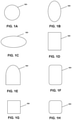
- FIGS. 1A-H are perimeter shapes for sites, site pads, and sleeve pads according to various embodiments.
- FIG. 2A is a top view of an insertion device in a “shipped” state according to an embodiment.
- FIG. 2B is a side cross-sectional view of the insertion device of FIG. 2A .
- FIG. 3A is a top perspective view of a cylinder hub of an insertion device according to an embodiment.
- FIG. 3B is an end perspective view of the cylinder hub of FIG. 3A .
- FIG. 4 is an end perspective view of a housing of an insertion device according to an embodiment.
- FIG. 5A is a side perspective view of a needle hub of an insertion device according to an embodiment.
- FIG. 5B is a side perspective view of a needle hub of an insertion device according to an embodiment.
- FIG. 5C is a side exploded view of a needle hub of an insertion device according to an embodiment.
- FIG. 6A is a top exploded view of a site according to an embodiment.
- FIG. 6B is a side exploded view of a site according to an embodiment.
- FIG. 6C is a back side view of a portion of a site according to an embodiment.
- FIG. 6D is a top view of a site according to an embodiment.
- FIG. 6E is a side cross-sectional view of the site of FIG. 6D .
- FIG. 6F is a side view of a septum of a site accordingly to an embodiment.
- FIG. 6G is a bottom view of a septum of a site accordingly to an embodiment.
- FIG. 6H is a back side view of a septum of a site accordingly to an embodiment.
- FIG. 6I is a front side view of a septum of a site accordingly to an embodiment.
- FIG. 6J is a perspective view of a septum of a site accordingly to an embodiment.
- FIG. 6K is a perspective view of a septum of a site accordingly to an embodiment.
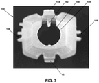
- FIG. 7 is an end perspective view of a sleeve of an insertion device according to an embodiment.
- FIG. 8A is a top view of an insertion device in a “triggered” state according to an embodiment.
- FIG. 8B is a side cross-sectional view of the insertion device of FIG. 8A .
- FIG. 9A is a top view of an insertion device in a “retracted” state according to an embodiment.
- FIG. 9B is a side cross-sectional view of the insertion device of FIG. 9A .
- FIG. 10 is a cross-sectional side view of a site providing a sensor with a multi-surfaced housing according to an embodiment.
- FIG. 11A is a top view of a site providing an elliptical patch pump or sensor with a multi-surfaced housing according to an embodiment.
- FIG. 11B is a top view of a site providing a rectangular patch pump or sensor with a multi-surfaced housing according to an embodiment.
- FIG. 12 is a schematic view of internal patch pump components according to an embodiment.
- FIG. 13 is a side cross-sectional view of an insertion device in a “shipped” state using a patch pump, presented as an alternate cross-sectional view of FIG. 2A , according to an embodiment.
- FIG. 14 is a side cross-sectional view of an insertion device in a “triggered” state using a patch pump, presented as an alternate cross-sectional view of FIG. 8A , according to an embodiment.
- FIG. 15 is a side cross-sectional view of an insertion device in a “retracted” state using a patch pump, presented as an alternate cross-sectional view of FIG. 9A , according to an embodiment.
- FIGS. 16A and 16B are side cross-sectional views of a patch pump retention arrangement with the cylinder hub prior to and during needle retraction, respectfully, according to an embodiment.
- FIG. 17 is a perspective view depicting retention fingers located at the end portion of the cylinder hub according to an embodiment.
- Embodiments relate to subcutaneous insertion systems comprising a site or other surface device to be applied to a patient and an insertion system for applying the site or other surface device to the patient, wherein the applying can include subcutaneous insertion of a cannula or other element, and related devices and methods.
- the site or other surface device can comprise a device applied to the skin of the patient and comprising a cannula, filament, wire, sensor or other subcutaneous element to be introduced at least partially subcutaneously into the skin of a patient.
- sites and other surface devices generally, whether for infusion, monitoring or some other purpose, will generally be referred to herein as sites.
- sites may refer to sensors or “patch pumps”.
- a subcutaneous insertion system comprises a site and an insertion device for applying the site to the skin of a user.
- the site comprises a surface for application to the skin of a patient and a subcutaneous element, such as a cannula, filament, wire, sensor or other subcutaneous element to be introduced at least partially subcutaneously into the skin of a patient, extending from the surface at an angle greater than 0 degrees and less than 90 degrees.
- the site can be preloaded in the insertion device, which comprises a needle configured to interact with the cannula or other subcutaneous element to insert the cannula or other subcutaneous element into the skin of the patient at an angle greater than 0 degrees and less than 90 degrees with respect to the surface of the skin of the patient as the site is applied to the surface of the skin of the patient by the insertion device.
- the insertion device is configured to retract and securely retain the needle in an inaccessible portion of the insertion device after insertion of the cannula or other subcutaneous element.
- the subcutaneous insertion system can further comprise a set comprising tubing and configured to be removably coupled to the site while on the skin of the patient in order to convey fluid from a source coupled to the set to the patient via the tubing, site and cannula.
- devices and elements other than tubing sets can be mechanically, electrically and/or communicatively coupled with the site following application to the skin of the patient.
- the site (or “payload”) can be circular, elliptical, rectangular, or modifications of those general shapes.
- examples discussed herein generally relate to an infusion site comprising a cannula. These examples are used without limitation or effect on the scope of the claims, as various other types of devices and elements are contemplated and may or may not fall within the scope of the claims.
- Some of these other devices and elements include patient monitoring systems and devices used to check or monitor one or more conditions of a patient (e.g., blood levels such as glucose, carbon dioxide, or oxygen) or body temperature, which also can include a device applied to the skin and comprising a cannula, filament, wire, sensor or other device introduced at least partially subcutaneously.
- Still other devices can be used in embodiments for application in or on the skin of a patient, including those with a different type of or without a subcutaneous element, with a plurality of subcutaneous elements, or with a subcutaneous element as well as surface elements (e.g., sensors or other devices configured to monitor a patient condition at the surface of the skin, independent of or in combination with a subcutaneous element).
- a site may comprise a “patch pump” or similar device which may include its own fluid reservoir, power mechanism, power supply, electronic circuitry and cannula insertion system.
- insertion device 100 comprises a housing 110 , a needle hub assembly 120 , a cylinder hub 130 , a biasing element 140 , a sleeve 150 , a cap 160 and a lock pin 170 .
- Lock pin 170 secures cap 160 to housing 110 via an aperture 172 in housing 110 and an aperture 174 in cap 160 and can also abut or otherwise interact with sleeve 150 to prevent sleeve 150 from moving within housing 110 and cap 160 . This can prevent inadvertent activation of insertion device 100 , such as if insertion device was inadvertently dropped or jarred, while also providing a child safety feature.
- Lock pin 170 can form part of or be coupled with a tear-away band 176 that can be part of cap 160 or housing 172 , such that removing tear-away band 176 removes lock pin 170 and enables cap 160 to be decoupled from housing 110 while also freeing sleeve 150 for movement.
- Cap 160 can comprise a label 161 in embodiments, wherein the label identifies at least one of a manufacturer of insertion device 100 , name of insertion device 100 , a serial number of insertion device 100 , a barcode or other computer-readable identifier, instructions or warnings with respect to use of insertion device 100 , and the like.
- Cap 160 can include a raised annular rib around its inner surface near the proximal end. This rib can be continuous or discontinuous. In some embodiments, the choice of cap design could be influenced by the sterilization method used on the device.
- Insertion device 100 can be preloaded with or otherwise comprise a site 180 including a central hub 181 extending upwardly from a top surface or side of site 180 .
- site 180 is not pre-loaded within insertion device 100 and instead can be coupled with insertion device 100 just prior to application of site 180 to the skin of the patient.
- Site 180 can be coupled with a site pad 182 and sleeve pad 184 on a bottom surface or side opposing its top surface.
- site 180 is differently configured and/or comprises a different type of device, the configuration of site pad 182 and/or sleeve pad 184 can vary, or one or both could be omitted or replaced by a different element.
- Site pad 182 can couple or interface between site 180 and sleeve pad 184 , while sleeve pad 184 can be configured to removably secure site 180 to sleeve 150 before application of site 180 to the skin of a patient.
- Sleeve pad 184 can comprise an adhesive layer, such as one comprising TEGADERM or another similar adhesive suitable for application to human skin or tissue, to removably couple site 180 to the skin of a patient after activation of device 100 , which separates sleeve pad 184 from sleeve 150 as site 180 is applied to the skin of the patient.
- the adhesive layer can be applied to or coupled with a bottom surface of sleeve pad 184 , or in another embodiment the adhesive layer can be applied to or coupled with a different surface of or coupled to site 180 .
- a top surface of sleeve pad 184 is visible.
- Sleeve pad 184 can also comprise a finger tab 186 , which can be an additional layer of material or an area free of adhesive between sleeve pad 184 and the skin of the patient to enable the patient or a clinician to easily grasp and remove site 180 from the skin of the patient or otherwise hold site 180 via sleeve pad 184 with no or reduced interaction with the adhesive layer.
- site 180 , site pad 182 and sleeve pad 184 can be precoupled with one another within insertion device 100 (i.e., combined or assembled together during manufacturing of insertion device 100 ), or in some embodiments they can be separate components combined upon activation of device 100 .
- site 180 and site pad 182 are precoupled with one another within insertion device 100 during manufacturing, and subsequently the combination is coupled with sleeve pad 184 , via an additional adhesive layer on a top surface of sleeve pad 184 and/or on a bottom surface of site pad 182 , only upon activation of device 100 to apply site 180 , along with site pad 182 and sleeve pad 184 , to the skin of a patient.
- each of site 180 , site pad 182 and sleeve pad 184 can be a variety of shapes. As shown in FIGS. 1A-H , the general perimeter 191 may be round, elliptical, oblong, rectangular, semi-rectangular, rounded rectangular, square, rounded square or some other shape in various embodiments.
- the site 180 , site pad 182 and sleeve pad 184 may have a combination of such perimeter shapes as well. In one embodiment, for example, site 180 and site pad 182 have generally round perimeters while sleeve pad 184 has a generally elliptical perimeter.
- FIG. 2A depicts a top view of insertion device 100 in which cap 160 is secured to housing 110 by lock pin 170
- FIG. 2B depicts a side sectional view of insertion device 100
- a subcutaneous element such as a cannula 188
- cannula 188 extends from the bottom surface of site 180 at an angle greater than 0 degrees and less than 90 degrees with respect to that bottom surface.
- cannula 188 can be at an angle ⁇ (see FIG. 6E ) of between about 20 degrees and about 50 degrees, such as between about 25 degrees and about 35 degrees, for example about 30 degrees.
- cannula 188 can instead comprise a wire, filament, sensor, or other device or element configured to be inserted at least partially subcutaneously.
- An embodiment comprising a cannula is discussed herein by way of example only.
- Site pad 182 and sleeve pad 184 each comprise an aperture 183 and 185 (see FIG. 1 ), respectively, that enables cannula 188 to pass through site pad 182 and sleeve pad 184 when site 180 is applied to the skin of a patient.
- Apertures 183 and 185 can be elliptical, which can be more easily compatible with the angle of cannula 188 , or round or some other shape.
- Apertures 183 and 185 can have the same or different shapes, circumferences, relative placements on site pad 182 and sleeve pad 184 , respectively, and other features and characteristics.
- FIGS. 2A and 2B depict insertion device 100 in a post-manufacturing shipped state, and in an embodiment in which site 180 is preloaded in insertion device, and cap 160 is secured to housing 110 by lock pin 170 and includes tear-away band 176 .
- Cap 160 comprises a cap post 162 extending upwardly or away from an inner bottom surface of cap 160 at a similar angle as cannula 188 .
- Cap post 162 is hollow or otherwise comprises an interior channel 164 to house cannula 188 in the shipped state.
- the top or open end of cap post 162 is configured to support site 180 .
- the open end of cap post 162 is stepped or graduated such that a first portion 166 of cap post 162 supports site 180 near one side or edge of site 180 and a second portion 168 of cap post 162 supports site 180 at or near its center, accommodating the relative angles between site 180 and cap post 162 .
- second portion 168 and one or both of apertures 183 and 185 are arranged to enable second portion 168 to pass therethrough and contact the bottom surface of site 180 proximate, such as adjacent to or at least partially around, cannula 180 .
- one or both of first and second portions 166 and 168 can be configured to engage with a corresponding portion of site 180 to more securely support site 180 within insertion device 100 .
- Site 180 is also supported or held in place within insertion device 100 by an end portion 132 of cylinder hub 130 and trigger rib 152 of sleeve 150 .
- End portion 132 and trigger rib 152 can abut and/or support at least a portion of a central hub 181 of site 180 .
- end portion 132 can further be configured to abut and/or support at least a portion of the top surface of site 180 .
- end portion 132 of cylinder hub 130 is also configured to support site 180 in an orientation in which the top and bottom surfaces of site 180 are neither parallel nor perpendicular with the sidewalls of housing 110 and cap 160 .
- the bottom surface of site 180 is generally parallel to the top surface of sleeve pad 184 .
- site 180 is generally parallel with an end portion 169 of cap 160 , wherein end portion 169 is not perpendicular with the sidewall of cap 160 and is not parallel with an end surface of housing 110 .
- the angle between end portion 169 and the sidewall of cap 160 is similar to the angle at which cannula 188 extends from the bottom surface of site 180 (i.e., an angle between about 20 degrees and about 50 degrees, such as between about 25 degrees and about 35 degrees, for example about 30 degrees, in various embodiments).
- end portion 169 of cap 160 is not parallel to the bottom surface of site 180 and the angle between end portion 169 of cap 160 and the sidewalls of housing 110 and cap 160 may be a different angle, such as a right angle.
- cylinder hub 130 is generally hollow and comprises a shoulder portion 131 and a body portion 133 .
- Shoulder portion 131 can have a generally ovular or oblong cross-section, while body portion 133 also can be generally ovular, oblong or round.
- body portion 133 tapers slightly (i.e., the cross-section diameter decreases) between shoulder portion 131 and a distal end of cylinder hub 130 .
- Shoulder portion 131 can comprise two tabs 134 configured to engage with shoulders 112 (see FIG. 2B ) of housing 110 to couple cylinder hub 130 and housing 110 with at least a portion of shoulder portion 131 abutting an inner surface of an end of housing 110 .
- an internal top surface 114 of housing 110 can comprise a standing circular rib 116 configured to interface with shoulder portion 131 to hold shoulder portion in place within housing 110 .
- Housing 110 also comprises guide ribs 118 and sleeve tabs 119 .
- Cylinder hub 130 further comprises apertures 136 (see FIG. 1 ) extending from a first end of cylinder hub 130 , through shoulder portion 131 via internal guides 135 that form a channel in shoulder portion 131 to connect with apertures 136 formed in body portion 133 .
- Apertures 136 are configured to guide needle hub 120 within cylinder hub 130 and extend from shoulder portion 131 to about a midpoint of body portion 133 .
- Apertures 136 are formed opposite each other, on opposing sides of cylinder hub 130 .
- Body portion 133 comprises an aperture 137 configured to interact with a corresponding tab on needle hub 120 .
- Body portion 133 also comprises a needle guide 138 and previously mentioned end portion 132 that abuts site 180 as discussed above.
- needle hub 120 is configured to be slidably arranged within the hollow cylinder hub 130 (see FIG. 3A ).
- Needle hub 120 comprises tabs 123 configured to slide within guides 135 and apertures 136 of cylinder hub 130 (see FIG. 3B ).
- Tabs 123 also can interact with biasing element 140 (see FIG. 1 ), such as to compress biasing element toward site 180 (as depicted in FIG. 2B ).
- Needle hub 120 further comprises needle retaining portion 124 and snap arm 126 . During use and operation, snap arm 126 interacts with both aperture 137 (see FIG.
- site 180 is depicted, along with septum 190 and site cap 187 .
- Septum 190 is configured to fit within central hub 181 and facilitate fluid communication between needle 122 and cannula 188 in use.
- septum 190 is asymmetrical, having a slanted lower portion 192 .
- An inner surface 189 of central hub 181 is correspondingly slanted to accommodate septum 190 .
- Site cap 187 fits on central hub 181 over septum 190 to secure septum 190 therewithin.
- needle 122 enters site 180 via a side aperture 194 formed in central hub 181 .
- Needle 122 passes through septum 190 within central hub 181 and exits site 180 via needle aperture 196 . As needle 122 passes through needle aperture 196 , needle 122 enters cannula 188 (not shown in FIGS. 6A and 6C ) to insert cannula into the skin of a patient as site 180 is applied to the skin of the patient. Needle 122 is then removed and retracted within insertion device 100 , as will be discussed more below.
- septum 190 is depicted from various perspectives, for use in a site 180 . Specifically, the views shown are side, bottom, back side, front side, and multiple perspective views, respectively. As shown, septum 190 is generally made up of a main body portion 193 , an upper protrusion 195 , and a slanted lower portion 192 .
- Main body portion 193 is generally a vertically disposed, cylindrical member which surrounds a cylindrical cavity 197 . Extending vertically from main body portion 193 is a tapered, generally conical, upper protrusion 195 .
- the main body portion 193 is merged with a smaller diameter, generally cylindrical, slanted lower portion 192 that extends across the bottom of the main body portion 193 in an angled manner.
- Lower portion 192 has a planar, angled face 198 at its lower end. This angled face 198 contains an arch shaped aperture 199 that provides a channel 177 that extends partially through the slanted lower portion 192 and merges with the cylindrical cavity 197 of the main body portion.
- the slanted lower portion 192 further contains a lower aperture 178 that provides access to the cylindrical cavity 197 from the bottom of the septum 190 . This lower aperture 178 further provides a small recess from the bottom surface of the lower portion 192 .
- the channel 177 formed within the septum 190 provides angled access for a cannula 188 that is inserted through a site 180 at various angles.
- the contours of the arch shaped aperture 199 and channel 177 provide a versatile and functional passage and arrangement for cannula insertion. Accordingly, the when the cannula 188 is inserted through the aperture 196 , wall 179 , and channel 177 of lower portion 192 , a convenient seal is made possible by the septum 190 .
- Sleeve 150 is depicted in FIG. 7 .
- Sleeve 150 comprises trigger rib 152 .
- Sleeve 150 further comprises tabs 154 and guide channels 156 , each of which interacts with a corresponding portion of housing 110 : tabs 154 can interlock with sleeve tabs 119 (see FIG. 4 ) while guide channels 156 can guide sleeve ribs 118 (see FIG. 4 ) on each side. The ends of guide channels 156 can prevent further relative movement of housing 110 and sleeve during operation.
- Cylinder hub 130 is configured to be arranged through central aperture 158 , while a rib 159 in which central aperture 158 is formed can be a stop or fixing point for biasing element 140 , such that biasing element 140 is arranged between tabs 123 of needle hub 120 and rib 159 in at least one operational state of insertion device 100 .
- Biasing element 140 can comprise a spring, such as a coil spring, in embodiment. In other embodiments, some other type or form of biasing element can be used. As discussed below, biasing element 140 is compressed during application of site 180 , and release of the compression retracts needle 122 during use and operation of insertion device 100 .
- Insertion device 100 is depicted in a “triggered” state.
- lock pin 170 , tear-away band 176 and cap 160 are removed.
- Insertion device 100 is placed on the skin of the patient, with the open bottom portion of sleeve 150 against and substantially parallel with the skin of the patient.
- Housing 110 is pushed toward the skin of the patient while sleeve 150 remains generally stationary with respect to the skin of the patient.
- housing 110 causes site 180 and cannula 188 , cylinder hub 130 , needle hub 120 and needle 122 to advance toward the skin of the patient until site pad 182 is in contact with sleeve pad 184 that is already in contact with the skin of the patient and needle 120 has inserted cannula 188 into the skin of the patient.
- biasing element 140 is compressed. This is generally the state depicted in FIG. 8B , although sleeve pad 184 is not specifically depicted in this view.
- cannula 188 would be inserted into the skin of a patient if so applied, and cannula 188 would enter the skin of the patient at an angle between 0 degrees and 90 degrees, as discussed above.
- cannula 188 is about 6 mm to about 25 mm long, such as about 13 mm long in one example embodiment and such as about 19 mm in another example embodiment.
- the length of cannula 188 can vary in other embodiments.
- Another advantage of the angled insertion of cannula 188 can be an increased resistance to potential escape of the medicament being infused, which might occur if a portion of the medicament were to follow the exterior surface of cannula 188 to the surface of the patient's skin.
- cannula 188 can be longer, such as twice as long or more, yet penetrate to the same depth within the subcutaneous layer of the patient's skin.
- trigger rib 152 causes snap arm 126 to disengage from aperture 137 (see FIG. 3A ). Because biasing element 140 has been compressed during the movement of housing 110 and cylinder hub 130 toward the skin and relative to sleeve 150 , disengagement of snap arm 126 from aperture 137 by trigger rib 152 causes needle hub 120 and needle 122 to be retracted upwardly away from the skin within cylinder hub 130 and housing 110 by the released force of compressed biasing element 140 , which engages with tabs 123 to retract needle hub 120 . Insertion device is then in a “retracted” state.
- Needle hub 120 is retracted within cylinder hub 130 and housing 110 until needle 122 is substantially or fully within cylinder hub 130 , such that it cannot be accessed or inadvertently “stick” someone after it has now been used to apply site 180 and insert cannula 188 .
- Biasing element 140 is generally relaxed, or at least less compressed than in either the “shipped” or “triggered” states.
- an infusion set can be coupled to site 180 to enable an infusion pump or other fluid source to deliver a fluid to the patient via site 180 , in an embodiment in which site 180 is used for infusion.
- infusion sets are disclosed in U.S. Pat. No. 9,192,717 to Cote et al., which is incorporated herein by reference in its entirety.
- the set can be coupled to site 180 in a plurality of different relative positions (i.e., to change the side or angle from which infusion tubing of the set extends from site 180 to increase comfort and convenience to the patient).
- an infusion set can be coupled to site 180 in at least different relative positions, such as with the needle of the set entering site 180 from one of four different sides spaced apart from another by about 90 degrees. In other embodiments, more or fewer relative coupling relationships between site 180 and the set are possible.
- a needle within the set passes through a side of central hub 180 and pierces septum 190 , establishing fluid communication between the needle (and medical tubing coupled thereto via the rest of the set, such as from an infusion pump) and cannula 188 .
- devices other than infusion sets and tubing can be coupled to site 180 .
- this coupling can be mechanical, electrical, communicative or some combination of these coupling modalities.
- a set or other type of mechanical coupler can be used in embodiments, or a set can be omitted.
- the configuration of site 180 can vary in embodiments, as can the configuration, size and orientation of some or all of the components of insertion device 100 .
- the configuration of portions of sleeve 150 , cylinder hub 130 and/or needle hub 120 which can interact with site 180 to abut and/or support site 180 within insertion device 100 , can vary from those depicted as the configuration or type of payload (e.g., site 180 ) of insertion device 100 varies.
- insertion device 100 can be used to apply, including subcutaneously, at least a portion of a site or other device at an angle between 0 degrees and 90 degrees to the skin of a patient.
- the insertion needle passageway through the site can always be used for attachment of a set buckle to the site after placement onto the skin of a patient.
- site 180 can comprise additional elements or devices that communicate, cooperate or support the subcutaneous element or that otherwise provide a desired function.
- site 180 can comprise a radio-frequency identification (RFID) tag, chip, circuit, memory, sensor, light-emitting diode (LED), user interface, or other device or feature.
- RFID radio-frequency identification
- LED light-emitting diode
- site 180 can communicate with an external device, such as a meter, smartphone, smart watch, tablet, handheld or bodyworn computer or device, laptop, network, computer terminal, data reader or virtually any other device.
- the communications can be wired or wireless and can utilize one or more communication techniques including WIFI, BLUETOOTH, near- or far-field communications, or other techniques.
- FIG. 10 provides a cross-sectional side view of one embodiment of a site 280 depicted in a similar orientation to site 180 shown in FIG. 6E .
- Site 280 provides a sensor 210 , such as an analyte sensor, in a multi-surfaced, generally disc-shaped housing 212 .
- the sensor 210 is shown with a proximal portion 214 as well as a sensing filament 216 extending from the generally flat bottom surface 218 of the housing 212 to distal portion 220 at an angle ⁇ . In some embodiments, angle ⁇ will be about 30 degrees.
- the angled, sensing filament 216 has advantages over a perpendicular filament as it can be twice as long and contact much more tissue in certain embodiments.
- housing 212 may include a printed circuit board 222 and associated electronics.
- sensors 210 of this type may be used for monitoring analytes, such as glucose, in bodily fluids (blood, interstitial fluid, or others) where the sensing filament is positioned below the skin surface and monitoring is in vivo.
- Housing 212 is shown with a generally planar top housing surface 224 and an angled side housing surface 226 along at least one side.
- the remaining side surface(s) 228 may be perpendicular to the top housing surface 224 or may gradually slope down to the bottom surface 218 , as depicted in FIG. 10 .
- the angled side surface 226 of the housing makes it possible to appropriately fit the site 280 within the confines of an angled insertion device 100 (or 300 ) having a housing 110 and sleeve 150 disposed similar to the arrangement depicted in FIG. 2B .
- the angled side surface is oriented at an angle generally consistent with the sensing filament 216 or other subcutaneous element.
- the partially angled housing surface configuration can permit mounting and delivery of site components which have a desired cross section, such as a circular cross-section. This cross-section can match a desired cross section of a sleeve 150 of an insertion device 100 , for example.
- Top housing surface 224 contains a clearance aperture 230 . This aperture 230 provides an angled hole for passage of an introducer needle 122 .
- the housing and sensor arrangement of the site 280 accordingly permit a sensor that may be introduced and secured by angled introduction of a needle 122 and sensing filament 216 .
- patch pumps refer to small infusion pumps that can be adhered directly to the skin for wear. Such patch pumps can be used to infuse a variety of fluids or medicaments. Patch pumps include insulin pumps which can provide insulin to diabetic users; however, their usefulness can extend beyond insulin delivery to the delivery of other medicaments. In some embodiments, patch pumps involve no tubing, readily adhere to the body, are small, lightweight, completely or partially disposable, and are capable of being worn and manipulated discreetly under clothing. Some patch pumps are controlled wirelessly by a separate controller.
- FIGS. 11A-17 and the corresponding description generally depict patch pumps (i.e. sites 380 ) and corresponding features of an insertion device 300 .
- This insertion device 300 should be understood to generally operate in a corresponding manner to insertion device 100 with some variations necessary for the accommodation of the particular dimensions and parameters of the site 380 rather than a site 180 . These differences include a different retention arrangement of the site 380 that is discussed in further detail in connection with FIGS. 13-17 . While the details of a patch pump site 380 are more specifically addressed below, a sensor site 280 of similar housing shapes and/or arrangements should be understood to be fully disclosed by this description as well.
- FIG. 11A is a top view of a site or elliptical patch with a multi-surfaced housing 312 according to an embodiment.
- the elliptical patch pump 380 includes a generally planar top housing surface 324 and an angled side housing surface 326 .
- the patch pump 380 is shaped and sized such that it can be applied by an angled insertion device 300 with a circular cross section across its sleeve 150 .
- Patch pumps 380 of a variety of shapes and sizes are possible, but must be appropriately shaped to fit within the cross section of the desired angled insertion device 300 .
- FIG. 11B is a top view of a site constituting a rectangular patch pump 380 a with a multi-surfaced housing 312 a according to an embodiment.
- the rectangular patch pump 380 a includes a generally planar top housing surface 324 a and an angled side housing surface 326 a .
- the patch pump 380 a is shaped and sized such that it can be applied by an angled insertion device 100 with a square cross section across its sleeve 150 .
- a patch pump 380 can generally contain an adhesive pad across its bottom surface when deployed on a user in certain embodiments, which will extend beyond and around the perimeter of the housing 312 .
- Adhesive pads of this type can be adapted for use over periods of long term wear in some embodiments.
- FIG. 12 sets forth a schematic diagram of the internal components of a patch pump 380 inside housing 312 .
- the housing 312 can be watertight or otherwise impermeably sealed in various embodiments.
- the patch pump 380 generally contains a fluid reservoir 332 , a drive mechanism 334 , a power supply 336 , electronic circuitry 338 and an angled access cannula insertion system 340 .
- the components are generally coupled with one another, but do not require tubes or similar components subject to occlusion or similar malfunction in certain embodiments.
- fluid reservoir 332 can hold a limited supply of insulin or other medicament.
- the fluid reservoir 332 may be replaceable.
- the fluid reservoir 332 may be disposable once the fluid reservoir 332 is used.
- Drive mechanism 334 can comprise a variety of types of pumping mechanisms sized for the patch pump and will generally be controlled by electric circuitry 338 .
- the electronic circuitry 338 can program fluid delivery and communications.
- Electronic circuitry 338 can include a controller or can be controlled wirelessly by a controller located outside the pump housing 312 .
- the power supply 336 can comprise one or more batteries in various embodiments.
- the angled access cannula insertion system 340 provides an access passageway and features which enable safe application of the patch pump 380 to a user. This cannula insertion system 340 can include all insertion related features and passages of the patch pump 380 and can be better understood in the subsequent figures and discussion of the application.
- FIG. 13 a side cross-sectional view of an insertion device 300 in a post-manufacturing “shipped” state, for use applying a preloaded patch pump 380 .
- This view is presented as an alternate cross-sectional view of FIG. 2A .
- a subcutaneous element such as a cannula 388 , extends from the bottom surface of patch pump 380 at an angle greater than 0 degrees and less than 90 degrees with respect to that bottom surface.
- cannula 388 can be at an angle ⁇ (see FIG. 16A ) of between about 20 degrees and about 50 degrees, such as between about 25 degrees and about 35 degrees, for example about 30 degrees.
- Site pad 182 and sleeve pad 184 each comprise an aperture that enables cannula 388 to pass through site pad 182 and sleeve pad 184 when patch pump 380 is applied to the skin of a patient.
- Patch pump 380 is preloaded in insertion device 300 , and cap 160 is secured to housing 110 by lock pin 170 and includes tear-away band 176 .
- the top or open end of cap post 162 is configured to support patch pump 380 with stepped or graduated features.
- no cap post 162 will be present for support of a patch pump 380 .
- support for the patch pump 380 can also rely on an arrangement of retention fingers 350 that can extended from the end portion 132 of cylinder hub 130 into the attachment aperture 352 of the patch pump 380 .
- End portion 132 of cylinder hub 130 is also configured to support patch pump 380 in an orientation in which the top surface 354 and bottom surface 356 of patch pump 380 are neither parallel nor perpendicular with the sidewalls of housing 110 and cap 160 .
- the bottom surface 356 of patch pump 380 is generally parallel with an end portion 169 of cap 160 , wherein end portion 169 is not perpendicular with the sidewall of cap 160 and is not parallel with an end surface of housing 110 .
- the angle between end portion 169 and the sidewall of cap 160 is similar to the angle at which cannula 388 extends from the bottom surface of patch pump 380 (i.e., an angle between about 20 degrees and about 50 degrees, such as between about 25 degrees and about 35 degrees, for example about 30 degrees, in various embodiments).
- end portion 169 of cap 160 is not parallel to the bottom surface of patch pump 380 and the angle between end portion 169 of cap and the sidewalls of housing 119 and cap 160 may be a different angle, such as a right angle.
- FIG. 14 is a side cross-sectional view of an insertion device depicted in a “triggered” state for applying a patch pump 380 .
- This is presented as an alternate cross-sectional view of FIG. 8A .
- lock pin 170 , tear-away band 176 and cap 160 have been removed and insertion device 300 has been placed on the skin of the patient.
- the open bottom portion of sleeve 150 has been placed against and parallel with the skin of the patient.
- Housing 110 has been pushed toward the skin while sleeve 150 remains generally stationary with respect to the skin.
- Patch pump 380 , cannula 388 , cylinder hub 130 , needle hub 120 and needle 122 have been advanced toward the skin until patch pump 380 is in contact with the skin and needle 120 has inserted cannula 388 into the skin.
- This arrangement would insert a cannula 388 into the skin of the patient at an angle between 0 degrees and 90 degrees.
- trigger rib 152 causes snap arm 126 to disengage from aperture 137 . Because biasing element 140 has been compressed during the movement of housing 110 and cylinder hub 130 toward the skin and relative to sleeve 150 , disengagement of snap arm 126 from aperture 137 by trigger rib 152 causes needle hub 120 and needle 122 to be retracted upwardly away from the skin within cylinder hub 130 and housing 110 by the released force of compressed biasing element 140 , which engages with tabs 123 (See FIG. 5A ) to retract needle hub 120 . Insertion device 300 is then in a “retracted” state.
- FIG. 15 is a side cross-sectional view of an insertion device 300 in a “retracted” state using a patch pump 380 .
- This view is presented as an alternate cross-sectional view of FIG. 9A .
- Needle hub 120 is retracted within cylinder hub 130 and housing 110 until needle 122 is substantially or fully within cylinder hub 130 , such that it cannot be accessed or inadvertently “stick” someone after it has now been used to apply patch pump 380 and insert cannula 388 .
- Biasing element 140 is generally relaxed, or at least less compressed than in either the “shipped” or “triggered” states.
- the needle 122 is retracted, leaving the cannula 388 of the patch pump 380 inserted in the desired patient location.
- retention fingers 350 of the cylinder hub 130 are permitted to disengage from the patch pump 380 .
- This disengagement results in the patch pump 380 being separated from the rest of the insertion device 300 . Accordingly, retraction of the needle allows the retention fingers 350 to move inward during removal. Operation of the retention fingers 350 is described in greater detail in FIGS. 16A-17 and the related disclosure.
- FIGS. 16A and 16B are side cross-sectional views of a patch pump retention arrangement with the cylinder hub 130 prior to and during needle retraction, respectfully.
- patch pump 380 having a housing 312 with a top housing surface 354 , angled side surface 355 , and bottom surface 356 is shown.
- the top housing surface 354 contains an attachment aperture 352 which provides an angled passageway 358 through the housing 312 at an angle that is generally parallel to that of the angled side surface 355 .
- the angled side surface 355 is oriented at an angle generally consistent with the cannula 388 or other subcutaneous element.
- the angled passageway 358 provides space for a needle 122 to pass through the housing 312 and a location for securing the patch pump 380 to the cylinder hub 130 of the insertion mechanism 300 until the needle 122 is retracted.
- the angled passageway 358 begins to extend inward from the attachment aperture 352 in an angled manner with a smooth surface diameter. Partially into the angled passageway 358 an annular constriction 360 protrudes inward from the perimeter before the angled passageway 358 again widens to a section 362 of smooth diameter that houses a self-sealing septum 364 .
- the angled passageway 358 is reduced to a final, narrow diameter passage 366 leading to the bottom housing surface 356 , out of which cannula 388 extends in an angled manner from the housing 312 .
- features of the cylinder hub 130 consisting of retention fingers 350 (also interchangeably and more specifically identified individually as 350 a , 350 b . . . etc. in the figures and description), extend into the angled passageway 358 .
- retention fingers 350 also interchangeably and more specifically identified individually as 350 a , 350 b . . . etc. in the figures and description.
- a first retention finger 350 a and a second retention finger 350 b are present, surrounded by a central passageway 368 .
- a greater number of retention fingers 350 can be present which are radially surrounded by the central passageway 368 in a spaced-apart manner.
- the retention fingers 350 have a generally smooth inner surface 370 partially surrounding the central passageway 368 which is in adjacent contact with the surface of the needle 122 extending therethrough.
- the outer surface portion 372 of the retention fingers 350 is generally smooth for a distance as it extends from the cylinder hub 130 into the contoured angled passageway 358 of the housing 312 .
- a recessed section 374 is present partway along the outer surface 372 as well as an outwardly extending tab 376 extends toward the passageway wall at or near the distal end of the retention finger 350 .
- the retention fingers 350 are engaged within the angled passageway 358 such that the outwardly extending tab 376 is located in the wider section 362 of the angled passageway 358 beyond the annular constriction 360 . In this position, the annular constriction 360 projects inwardly toward recessed section 374 of the retention finger 350 .
- the retention fingers 350 are generally held in place when needle 122 extends through the central passageway 368 as the needle 122 interferes with the ability of the retention fingers 350 to flex inwardly so that the annular constriction 360 and outwardly extending tabs 376 interfere with movement past each other.
- FIG. 16B shows the release of the patch pump 380 upon retraction of the needle 122 .
- Medicament reaches the top end of the cannula 388 through a cavity, not shown, below self-sealing septum 364 that is in fluid communication with fluid reservoir 332 .
- FIG. 17 is a perspective view depicting one embodiment of a pair of retention fingers 350 a and 350 b that could be used as part of the end portion 132 of the cylinder hub 130 .
- Each retention finger 350 a and 350 b has a smooth inner surface and a projecting tab 376 a and 376 b extending outwardly at respective distal ends of the retention fingers 350 a and 350 b .
- the tab portion consists of a first projecting flat surface, a flat end surface, and an angled flat surface extending between the first projecting flat surface and the flat end surface.
- Various shapes and sizes may be used for tabs to provide secure engagement within the contoured passageway. In general, however, rigid outward extension of the tabs 376 a and 376 b are held in place and made possible based on interference of a central needle 122 , when present, with the inside smooth surfaces of the retention fingers 350 a and 350 b.
Landscapes
- Health & Medical Sciences (AREA)
- Life Sciences & Earth Sciences (AREA)
- Engineering & Computer Science (AREA)
- Public Health (AREA)
- Heart & Thoracic Surgery (AREA)
- Animal Behavior & Ethology (AREA)
- General Health & Medical Sciences (AREA)
- Veterinary Medicine (AREA)
- Biomedical Technology (AREA)
- Hematology (AREA)
- Anesthesiology (AREA)
- Biophysics (AREA)
- Vascular Medicine (AREA)
- Medical Informatics (AREA)
- Physics & Mathematics (AREA)
- Pathology (AREA)
- Molecular Biology (AREA)
- Surgery (AREA)
- Computer Networks & Wireless Communication (AREA)
- Dermatology (AREA)
- Pulmonology (AREA)
- Infusion, Injection, And Reservoir Apparatuses (AREA)
- Media Introduction/Drainage Providing Device (AREA)
Priority Applications (1)
| Application Number | Priority Date | Filing Date | Title |
|---|---|---|---|
| US16/097,449 US11229753B2 (en) | 2016-04-29 | 2017-04-25 | Subcutaneous insertion systems, devices and related methods |
Applications Claiming Priority (3)
| Application Number | Priority Date | Filing Date | Title |
|---|---|---|---|
| US201662329352P | 2016-04-29 | 2016-04-29 | |
| PCT/US2017/029353 WO2017189541A1 (en) | 2016-04-29 | 2017-04-25 | Subcutaneous insertion systems, devices and related methods |
| US16/097,449 US11229753B2 (en) | 2016-04-29 | 2017-04-25 | Subcutaneous insertion systems, devices and related methods |
Related Parent Applications (1)
| Application Number | Title | Priority Date | Filing Date |
|---|---|---|---|
| PCT/US2017/029353 A-371-Of-International WO2017189541A1 (en) | 2016-04-29 | 2017-04-25 | Subcutaneous insertion systems, devices and related methods |
Related Child Applications (1)
| Application Number | Title | Priority Date | Filing Date |
|---|---|---|---|
| US17/549,373 Continuation US11998727B2 (en) | 2016-04-29 | 2021-12-13 | Subcutaneous insertion systems; devices and related methods |
Publications (2)
| Publication Number | Publication Date |
|---|---|
| US20190151567A1 US20190151567A1 (en) | 2019-05-23 |
| US11229753B2 true US11229753B2 (en) | 2022-01-25 |
Family
ID=60161082
Family Applications (2)
| Application Number | Title | Priority Date | Filing Date |
|---|---|---|---|
| US16/097,449 Active 2037-11-14 US11229753B2 (en) | 2016-04-29 | 2017-04-25 | Subcutaneous insertion systems, devices and related methods |
| US17/549,373 Active US11998727B2 (en) | 2016-04-29 | 2021-12-13 | Subcutaneous insertion systems; devices and related methods |
Family Applications After (1)
| Application Number | Title | Priority Date | Filing Date |
|---|---|---|---|
| US17/549,373 Active US11998727B2 (en) | 2016-04-29 | 2021-12-13 | Subcutaneous insertion systems; devices and related methods |
Country Status (4)
| Country | Link |
|---|---|
| US (2) | US11229753B2 (de) |
| EP (2) | EP3448491B1 (de) |
| AU (2) | AU2017257665B2 (de) |
| WO (1) | WO2017189541A1 (de) |
Cited By (1)
| Publication number | Priority date | Publication date | Assignee | Title |
|---|---|---|---|---|
| US20220096746A1 (en) * | 2018-08-29 | 2022-03-31 | Insulet Corporation | Drug delivery system with sensor having optimized communication and infusion site |
Families Citing this family (5)
| Publication number | Priority date | Publication date | Assignee | Title |
|---|---|---|---|---|
| CN109998555B (zh) * | 2019-04-30 | 2023-12-15 | 苏州百孝医疗科技有限公司 | 一种受体生理参数测量系统 |
| US11771882B2 (en) * | 2019-08-20 | 2023-10-03 | Becton, Dickinson And Company | Catheter adapters |
| KR102384074B1 (ko) * | 2020-05-22 | 2022-04-07 | 주식회사 노바메디 | 주사 바늘 장치 |
| KR102531521B1 (ko) * | 2021-01-05 | 2023-05-15 | 인싸이토(주) | 마이크로 니들을 이용한 경사 주사침 세트 및 경사 주사침 |
| US20220240785A1 (en) * | 2021-01-30 | 2022-08-04 | Microvascular Health Solutions, LLC | Method and apparatus for microvascular vessel imaging |
Citations (162)
| Publication number | Priority date | Publication date | Assignee | Title |
|---|---|---|---|---|
| US3094989A (en) | 1960-06-10 | 1963-06-25 | Int Treuhand A G | Ampulla incorporating an injection syringe |
| US3547119A (en) | 1967-12-08 | 1970-12-15 | Baxter Laboratories Inc | Catheter assembly |
| US4235234A (en) | 1978-11-30 | 1980-11-25 | Martin John K Iii | Subcutaneous injection system |
| US4378015A (en) | 1981-12-21 | 1983-03-29 | Wardlaw Stephen C | Automatic injecting syringe |
| US4531937A (en) | 1983-01-24 | 1985-07-30 | Pacesetter Systems, Inc. | Introducer catheter apparatus and method of use |
| US4563177A (en) | 1983-12-22 | 1986-01-07 | Kamen Dean L | Catheter stabilization pad |
| US4645495A (en) | 1985-06-26 | 1987-02-24 | Vaillancourt Vincent L | Vascular access implant needle patch |
| US4747831A (en) | 1987-04-29 | 1988-05-31 | Phase Medical, Inc. | Cannula insertion set with safety retracting needle |
| US4755173A (en) | 1986-02-25 | 1988-07-05 | Pacesetter Infusion, Ltd. | Soft cannula subcutaneous injection set |
| US4781695A (en) * | 1986-07-11 | 1988-11-01 | Dalton Michael J | Implantable fluid dispenser |
| US4805791A (en) | 1988-05-04 | 1989-02-21 | Continental White Cap, Inc. | Band with lock ring for tamper-evident cap |
| US4813939A (en) | 1987-12-04 | 1989-03-21 | Joel Marcus | Winged infusion apparatus for patient implantable access ports |
| CA1272423A (en) | 1986-02-25 | 1990-08-07 | Peter C. Lord | Soft cannula subcutaneous injection set and method of making same |
| US4994042A (en) | 1989-10-02 | 1991-02-19 | Vadher Dinesh L | Combined catheter and needle |
| EP0451040A1 (de) | 1990-04-03 | 1991-10-09 | Robert L. Parker | Intravenöser Katheter als geschlossenes System |
| US5092853A (en) | 1991-02-04 | 1992-03-03 | Couvertier Ii Douglas | Automatic retractable medical needle and method |
| US5122119A (en) | 1989-09-07 | 1992-06-16 | Dieter Lucas | Hypodermic syringe |
| US5129884A (en) | 1990-01-16 | 1992-07-14 | Dysarz Edward D | Trap in barrel one handed retracted intervenous catheter device |
| US5135496A (en) | 1989-05-17 | 1992-08-04 | Arzneimittel Gmbh Apotheker Vetter & Co. | Tamper-proof hypodermic syringe assembly |
| US5135502A (en) | 1987-12-03 | 1992-08-04 | Medfusion Inc. | Solid introducer for catheter to a port and method of use |
| US5137516A (en) | 1989-11-28 | 1992-08-11 | Glaxo Group Limited | Triggered application device for medicament to be more descriptive of the invention |
| US5167632A (en) | 1992-01-24 | 1992-12-01 | New Potency Products, Inc. | Syringe |
| US5176650A (en) | 1992-02-10 | 1993-01-05 | Haining Michael L | Intravenous catheter and insertion device |
| US5176662A (en) | 1990-08-23 | 1993-01-05 | Minimed Technologies, Ltd. | Subcutaneous injection set with improved cannula mounting arrangement |
| US5257980A (en) | 1993-04-05 | 1993-11-02 | Minimed Technologies, Ltd. | Subcutaneous injection set with crimp-free soft cannula |
| US5391151A (en) | 1991-01-15 | 1995-02-21 | Survival Technology, Inc. | Subcutaneous injector |
| US5451210A (en) | 1991-04-29 | 1995-09-19 | Lifequest Medical, Inc. | System and method for rapid vascular drug delivery |
| US5522803A (en) | 1993-03-09 | 1996-06-04 | Pharma Plast International A/S | Infusion set for an intermittent or continuous administration of a therapeutical substance |
| US5545143A (en) | 1993-01-21 | 1996-08-13 | T. S. I. Medical | Device for subcutaneous medication delivery |
| WO1996032981A1 (en) | 1995-04-17 | 1996-10-24 | Med Design Corporation | Safety stylet for intravenous catheter insertion |
| US5573510A (en) | 1994-02-28 | 1996-11-12 | Isaacson; Dennis R. | Safety intravenous catheter assembly with automatically retractable needle |
| US5575777A (en) | 1993-11-15 | 1996-11-19 | Becton Dickinson And Company | Retractable needle cannula insertion set with refinements to better control leakage, retraction speed and reuse |
| US5584813A (en) | 1995-06-07 | 1996-12-17 | Minimed Inc. | Subcutaneous injection set |
| US5591188A (en) | 1994-04-12 | 1997-01-07 | Wais-Med Lmt, A Subsidiary Company Of Teic Technion Enterpreneurial Incubator Ltd. | Surgical instrument for impact insertion of an intraosseous trocar-needle |
| US5676156A (en) | 1991-08-14 | 1997-10-14 | Yoon; Inbae | Automatic retractable safety penetrating instrument |
| FR2752164A1 (fr) | 1996-08-09 | 1998-02-13 | Vygon | Dispositif pour realiser une ponction a travers la peau au moyen d'une aiguille |
| US5738641A (en) | 1996-07-31 | 1998-04-14 | Watson; Robert L. | Blood withdrawal patch |
| US5817058A (en) | 1996-12-23 | 1998-10-06 | Shaw; Thomas J. | Retractable catheter introducer structure |
| US5833666A (en) | 1993-11-23 | 1998-11-10 | Uresil Corporation | Catheter fixation assembly |
| US5848990A (en) | 1993-10-22 | 1998-12-15 | Hoffmann-La Roche Inc. | Device for introducing active substance into a patient |
| US5848989A (en) | 1997-06-05 | 1998-12-15 | Davinci Biomedical Research Products, Inc. | Implantable port with low profile housing for delivery/collection of fluids and implantation method |
| US5851197A (en) | 1997-02-05 | 1998-12-22 | Minimed Inc. | Injector for a subcutaneous infusion set |
| WO1998058693A1 (en) | 1997-06-20 | 1998-12-30 | Maersk Medical A/S | Subcutaneous infusion set |
| US5865842A (en) | 1996-08-29 | 1999-02-02 | Medtronic, Inc. | System and method for anchoring brain stimulation lead or catheter |
| US5873856A (en) | 1995-06-22 | 1999-02-23 | Pharmacia Ab | Limited depth penetration needle housing |
| WO1999033504A1 (en) | 1997-12-31 | 1999-07-08 | Minimed Inc. | Insertion device for an insertion set and method of using the same |
| WO1999034739A1 (en) | 1998-01-12 | 1999-07-15 | Roenborg Steen Meier | An injection unit |
| US5947931A (en) | 1989-07-24 | 1999-09-07 | Venetec International, Inc. | Tube fitting anchoring system |
| DE29905072U1 (de) | 1998-03-20 | 1999-09-09 | Maersk Medical A/S, Lynge | Subkutane Infusionsvorrichtung |
| US5954643A (en) | 1997-06-09 | 1999-09-21 | Minimid Inc. | Insertion set for a transcutaneous sensor |
| US5971950A (en) | 1983-01-24 | 1999-10-26 | Icu Medical, Inc. | Medical connector |
| US5980506A (en) | 1998-03-20 | 1999-11-09 | Mathiasen; Orla | Subcutaneous infusion device |
| JPH11347120A (ja) | 1998-05-14 | 1999-12-21 | Disetronic Licensing Ag | カテ―テルヘッド |
| US6056718A (en) | 1998-03-04 | 2000-05-02 | Minimed Inc. | Medication infusion set |
| US6074369A (en) | 1998-02-20 | 2000-06-13 | Becton, Dickinson And Company | Low-profile automatic injection device with self-emptying reservoir |
| US6077244A (en) | 1998-04-30 | 2000-06-20 | Mdc Investment Holdings, Inc. | Catheter insertion device with retractable needle |
| US6086575A (en) | 1998-03-20 | 2000-07-11 | Maersk Medical A/S | Subcutaneous infusion device |
| US6093172A (en) | 1997-02-05 | 2000-07-25 | Minimed Inc. | Injector for a subcutaneous insertion set |
| JP2000254225A (ja) | 1999-03-05 | 2000-09-19 | Medikit Kk | 安全留置針 |
| US6123690A (en) | 1998-03-20 | 2000-09-26 | Maersk Medical A/S | Subcutaneous infusion device |
| US6159181A (en) | 1998-04-18 | 2000-12-12 | Owen Mumford Limited Of Brook Hill | Injection device |
| US6191338B1 (en) | 1998-11-19 | 2001-02-20 | Kurt Haller | Adhesive bandage, matrix, and methods of removal |
| US20010039387A1 (en) | 2000-04-04 | 2001-11-08 | Wlodzimierz Rutynowski | Arrangement regulating depth of the puncture, used in the device for puncturing |
| US20010053889A1 (en) * | 1998-05-14 | 2001-12-20 | Rolf Marggi | Catheter head for subcutaneous administration of an active substance |
| US20020010423A1 (en) | 1997-06-16 | 2002-01-24 | Elan Corporation Plc | Pre-filled drug-delivery device and method of manufacture and assembly of same |
| US20020022855A1 (en) | 1997-12-31 | 2002-02-21 | Bobroff Randa M. | Insertion device for an insertion set and method of using the same |
| US6355021B1 (en) | 1998-07-14 | 2002-03-12 | Maersk Medical A/S | Medical puncturing device |
| US20020072720A1 (en) * | 2000-12-11 | 2002-06-13 | Hague Clifford W. | Rigid soluble materials for use with needle-less infusion sets, sensor sets and injection devices and methods of making the same |
| US20020077599A1 (en) | 2000-12-19 | 2002-06-20 | Animas Corporation | Transcutaneous inserter for low-profile infusion sets |
| US20020082543A1 (en) | 2000-12-14 | 2002-06-27 | Jung-Hwan Park | Microneedle devices and production thereof |
| US6419699B1 (en) | 1999-04-14 | 2002-07-16 | Mcghan Medical Corporation | Universal implant fill connector |
| US6428515B1 (en) | 2000-06-01 | 2002-08-06 | Venetec International, Inc. | Anchoring system for leur lock connector |
| US20020123724A1 (en) | 2001-03-04 | 2002-09-05 | Douglas Joel S. | Infusion hub assembly and fluid line disconnect system |
| US20020123740A1 (en) | 2000-11-09 | 2002-09-05 | Flaherty J. Christopher | Transcutaneous delivery means |
| US6450992B1 (en) | 1999-07-02 | 2002-09-17 | Smith & Nephew, Inc. | Cannula interface |
| WO2002081012A2 (de) | 2001-04-06 | 2002-10-17 | Disetronic Licensing Ag | Infusionsset |
| WO2002083206A2 (en) | 2001-04-13 | 2002-10-24 | Nipro Diabetes Systems | Infusion set with tape |
| US20020173769A1 (en) | 2001-05-18 | 2002-11-21 | Gray Larry B. | Infusion set for a fluid pump |
| WO2002100467A2 (en) | 2001-06-08 | 2002-12-19 | Eli Lilly And Company | Needle hiding assembly for a medication injector |
| WO2002102442A1 (en) | 2001-06-14 | 2002-12-27 | Occupational & Medical Innovations Ltd | A retractable needle assembly for a catheter and which uses an elastomeric member to retract the needle |
| US20030014018A1 (en) | 2000-08-02 | 2003-01-16 | Lucio Giambattista | Pen needle and safety shield system |
| US6517517B1 (en) | 2000-06-08 | 2003-02-11 | Mayo Foundation For Medical Education And Research | Automated injection device for administration of liquid medicament |
| US20030060776A1 (en) | 2000-03-01 | 2003-03-27 | Hanspeter Heiniger | Disposable injector cap |
| US20030060798A1 (en) | 2001-09-21 | 2003-03-27 | Fischer Gregory A. | Method and device for the iontophoretic delivery of a drug |
| US20030060781A1 (en) | 2001-09-27 | 2003-03-27 | Mogensen Lasse Wesseltoft | Injector device for placing a subcutaneous infusion set |
| US6549810B1 (en) | 1999-12-01 | 2003-04-15 | Vertis Neuroscience, Inc. | Percutaneous electrical therapy system with electrode depth control |
| US6572586B1 (en) | 2000-07-25 | 2003-06-03 | Animas Corporation | Low profile infusion set |
| US20030109829A1 (en) | 2001-09-28 | 2003-06-12 | Mogensen Lasse Wesseltoft | Injector device for placing a subcutaneous infusion set |
| US6579267B2 (en) | 2001-01-05 | 2003-06-17 | Applied Diabetes Research, Inc. | Pivoting joint infusion assembly |
| US20030158520A1 (en) | 1997-02-05 | 2003-08-21 | Medtronic Minimed, Inc. | Insertion device for an insertion set and method of using the same |
| US6620136B1 (en) | 1999-02-18 | 2003-09-16 | Medsafe Technologies, Llc | Retractable I-V catheter placement device |
| US20030181863A1 (en) * | 2000-11-09 | 2003-09-25 | Ackley Donald E. | Microneedle adapter |
| DE20220543U1 (de) | 2002-11-29 | 2003-10-02 | Disetronic Licensing Ag, Burgdorf | Katheterkopf mit verschließbarem Dichtelement |
| US20030225374A1 (en) | 2002-02-12 | 2003-12-04 | Orla Mathiasen | Infusion device with needle shield |
| US20030236498A1 (en) | 1998-03-23 | 2003-12-25 | Joseph Gross | Device for measuring volume of drug |
| US20040002682A1 (en) | 1997-02-05 | 2004-01-01 | Medtronic Minimed, Inc. | Insertion device for an insertion set and method of using the same |
| US6736797B1 (en) | 1998-06-19 | 2004-05-18 | Unomedical A/S | Subcutaneous infusion set |
| US6749589B1 (en) | 2000-01-18 | 2004-06-15 | Sterling Medications, Inc. | Subcutaneous injection set for use with a reservoir that has a septum |
| US20040116866A1 (en) | 2002-12-17 | 2004-06-17 | William Gorman | Skin attachment apparatus and method for patient infusion device |
| US20040138612A1 (en) | 2002-07-22 | 2004-07-15 | Shermer Charles D. | Patch-like infusion device |
| US20040143216A1 (en) | 2002-08-30 | 2004-07-22 | Spectrx, Inc. | Adapter connector for an infusion set and inserter system |
| US20040147877A1 (en) | 2003-01-27 | 2004-07-29 | Heuser Richard R | Catheter introducer system |
| US20040162521A1 (en) | 2002-10-07 | 2004-08-19 | Henrik Bengtsson | Needle device comprising a plurality of needles |
| EP1329233B1 (de) | 2001-12-28 | 2004-09-01 | CANE' S.r.l. | Behälter für wegwerfbare Nadel |
| US20040199123A1 (en) | 2003-04-01 | 2004-10-07 | Nielsen Jens Egebjerg | Infusion device and an adhesive sheet material and a release liner |
| US20040215151A1 (en) | 2001-07-28 | 2004-10-28 | Jeremy Marshall | Injection devices |
| WO2004101071A2 (en) | 2003-05-09 | 2004-11-25 | Medsolve Technologies, L.L.C. | Infusion hub assembly and inserter |
| US20040260250A1 (en) | 2003-06-18 | 2004-12-23 | Harris R. Bradley | Infusion device with safety guard |
| US20050075606A1 (en) | 1998-07-31 | 2005-04-07 | Michael Botich | Retractable needle medical device |
| US20050090779A1 (en) | 2002-03-15 | 2005-04-28 | Osypka Thomas P. | Locking vascular introducer assembly with adjustable hemostatic seal |
| US20050101912A1 (en) | 2003-11-10 | 2005-05-12 | Mark Faust | Device and method for insertion of a cannula of an infusion device |
| US20050101932A1 (en) | 2003-11-10 | 2005-05-12 | Steve Cote | Subcutaneous infusion device and device for insertion of a cannula of an infusion device and method |
| US20050101910A1 (en) | 2003-11-10 | 2005-05-12 | Medtronic Minimed, Inc. | Subcutaneous infusion set |
| US20050101933A1 (en) | 2003-11-10 | 2005-05-12 | James Marrs | Subcutaneous infusion device and method |
| US20050107743A1 (en) | 2003-11-18 | 2005-05-19 | Fangrow Thomas F.Jr. | Infusion set |
| US20050113761A1 (en) | 2003-11-10 | 2005-05-26 | Mark Faust | Subcutaneous infusion device and method including release feature for adhesive portion |
| US20050131346A1 (en) | 2002-02-26 | 2005-06-16 | Douglas Joel S. | Insertion device for an insertion set and method of using the same |
| US6923791B2 (en) | 2003-03-31 | 2005-08-02 | Sterling Medivations, Inc. | Infusion device having offset flow path |
| US20050215979A1 (en) | 2004-03-26 | 2005-09-29 | Grete Kornerup | Infusion set and injector device for infusion set |
| US20050240154A1 (en) * | 2004-04-21 | 2005-10-27 | Unomedical A/S: | Infusion set with patch |
| US20050283114A1 (en) | 2004-06-16 | 2005-12-22 | Timothy Bresina | Device and method for insertion of a cannula of an infusion device |
| US20060041224A1 (en) | 2003-02-12 | 2006-02-23 | Unomedical A/S | Cover |
| US7018344B2 (en) | 2003-01-21 | 2006-03-28 | Becton, Dickinson And Company | Retractable needle shielding device |
| US20060129090A1 (en) | 2004-12-03 | 2006-06-15 | Medtronic Minimed, Inc. | Multi-position infusion set device and process |
| US20060173413A1 (en) | 2004-12-21 | 2006-08-03 | Taiject Medical Device Co., Ltd. | Intravenous catheter insertion device with retractable needle |
| US7129389B1 (en) | 2002-10-29 | 2006-10-31 | Robert Watson | Puncture site patch |
| US20070066955A1 (en) * | 2003-10-21 | 2007-03-22 | Novo Nordisk A/S | Reservoir device with integrated mounting means |
| US20070276355A1 (en) * | 2004-02-18 | 2007-11-29 | Nielsen Jens E | Infusion Device Provided with Septum Housing |
| US7303543B1 (en) | 2004-12-03 | 2007-12-04 | Medtronic Minimed, Inc. | Medication infusion set |
| WO2008022476A1 (en) | 2006-08-24 | 2008-02-28 | F. Hoffmann-La Roche Ag | Insertion device for insertion heads, in particular for infusion sets |
| US20080071156A1 (en) | 2004-07-13 | 2008-03-20 | Dexcom, Inc. | Transcutaneous analyte sensor |
| US20080103450A1 (en) | 2006-10-31 | 2008-05-01 | James Marrs | Subcutaneous Infusion Device and Method including Tapered Cannula |
| US20080154205A1 (en) | 2005-10-19 | 2008-06-26 | Animas Corporation | Safety infusion set |
| USD576267S1 (en) | 2003-10-15 | 2008-09-02 | Unomedical A/S | Medical infusion device |
| US20080243051A1 (en) | 2007-03-30 | 2008-10-02 | Animas Corporation | Torsion bar-based cannula insertion device |
| US20090012472A1 (en) * | 2004-09-22 | 2009-01-08 | Novo Nordisk A/S | Medical Device with Cannula Inserter |
| US20090076453A1 (en) * | 2005-12-23 | 2009-03-19 | Signe Thorning Mejlhede | Device for Administration |
| US20090124979A1 (en) | 2007-09-17 | 2009-05-14 | Icu Medical, Inc | Insertion devices for infusion devices |
| US20090143763A1 (en) * | 2006-06-07 | 2009-06-04 | Martin Wyss | Rotatable infusion set |
| US20090215979A1 (en) | 2005-02-08 | 2009-08-27 | Novo Nordisk A/S | Process for the preparation of alkoxyamine functionalized polyethylene glycols |
| US7594902B2 (en) * | 2002-09-12 | 2009-09-29 | Disetronic Licensing Ag | Catheter head with catheter drain in discrete rotational positions |
| US20100049129A1 (en) | 2008-08-20 | 2010-02-25 | Hiroyuki Yokoi | Inserter |
| US20100063453A1 (en) * | 2007-02-02 | 2010-03-11 | Julie Grundtvig Theander | Gateway Device |
| US20100217105A1 (en) | 2006-11-28 | 2010-08-26 | Ofer Yodfat | Insertion device and method for inserting a subcutaneously insertable element into body |
| WO2011014492A1 (en) | 2009-07-29 | 2011-02-03 | Smiths Medical Asd, Inc. | Device and method for insertion of a cannula of an infusion device |
| US7931615B2 (en) | 2006-02-07 | 2011-04-26 | Icu Medical, Inc. | Infusion set |
| US20110125106A1 (en) | 2008-06-10 | 2011-05-26 | Shl Group Ab | Injection Needle Assembly |
| US7985199B2 (en) * | 2005-03-17 | 2011-07-26 | Unomedical A/S | Gateway system |
| US8157773B2 (en) * | 2004-07-21 | 2012-04-17 | Animas Corporation | Method and systems for providing an infusion device interface |
| US8226614B2 (en) * | 2005-11-03 | 2012-07-24 | Patton Medical Devices, Lp | Fluid delivery devices, systems and methods |
| US8303545B2 (en) * | 2007-09-07 | 2012-11-06 | Stat Medical Devices, Inc. | Infusion device and method of using and making the same |
| US8343115B2 (en) | 2001-01-05 | 2013-01-01 | Applied Diabetes Research, Inc. | Low profile pivoting joint infusion assembly |
| US20130274576A1 (en) * | 2012-04-16 | 2013-10-17 | PicoLife Technologies | Medication delivery device with multi-reservoir cartridge system and related methods of use |
| US20140039453A1 (en) | 2012-07-31 | 2014-02-06 | Becton, Dickinson And Company | Subcutaneous Infusion Set With Side Port Fluid Connector |
| US20140088555A1 (en) * | 2012-09-24 | 2014-03-27 | Po-Ying Li | Systems and Methods for Electrolysis Pump Control |
| US20160296695A1 (en) | 2015-04-08 | 2016-10-13 | Cequr Sa | Combined medicament fill and cannula insertion device |
| US20160339172A1 (en) | 2015-05-18 | 2016-11-24 | Tandem Diabetes Care, Inc. | Patch pump cartridge attachment |
| US9662440B2 (en) * | 2006-12-22 | 2017-05-30 | Roche Diabetes Care, Inc. | Systems, devices and methods for sustained delivery of a therapeutic fluid |
| US9795777B2 (en) * | 2011-12-07 | 2017-10-24 | Becton, Dickinson And Company | Infusion device with releasable fluid connector |
| US10076606B2 (en) * | 2007-12-10 | 2018-09-18 | Medtronic Minimed, Inc. | Insertion devices, insertion needles, and related methods |
| US10307532B2 (en) * | 2010-06-18 | 2019-06-04 | Roche Diabetes Care, Inc. | Infusion site interfaces and insertion devices for infusion site interfaces |
| US10434285B2 (en) * | 2011-02-09 | 2019-10-08 | Becton, Dickinson And Company | Self-contained inserter for drug delivery infusion set |
Family Cites Families (2)
| Publication number | Priority date | Publication date | Assignee | Title |
|---|---|---|---|---|
| WO2006102412A2 (en) * | 2005-03-21 | 2006-09-28 | Abbott Diabetes Care, Inc. | Method and system for providing integrated medication infusion and analyte monitoring system |
| KR20090117749A (ko) * | 2007-02-02 | 2009-11-12 | 우노메디컬 에이/에스 | 약물 공급장치 |
-
2017
- 2017-04-25 EP EP17790248.3A patent/EP3448491B1/de active Active
- 2017-04-25 EP EP24195561.6A patent/EP4442297A3/de active Pending
- 2017-04-25 WO PCT/US2017/029353 patent/WO2017189541A1/en not_active Ceased
- 2017-04-25 AU AU2017257665A patent/AU2017257665B2/en active Active
- 2017-04-25 US US16/097,449 patent/US11229753B2/en active Active
-
2021
- 2021-12-13 US US17/549,373 patent/US11998727B2/en active Active
-
2022
- 2022-02-15 AU AU2022200990A patent/AU2022200990B2/en active Active
Patent Citations (257)
| Publication number | Priority date | Publication date | Assignee | Title |
|---|---|---|---|---|
| US3094989A (en) | 1960-06-10 | 1963-06-25 | Int Treuhand A G | Ampulla incorporating an injection syringe |
| US3547119A (en) | 1967-12-08 | 1970-12-15 | Baxter Laboratories Inc | Catheter assembly |
| US4235234A (en) | 1978-11-30 | 1980-11-25 | Martin John K Iii | Subcutaneous injection system |
| US4378015A (en) | 1981-12-21 | 1983-03-29 | Wardlaw Stephen C | Automatic injecting syringe |
| US5971950A (en) | 1983-01-24 | 1999-10-26 | Icu Medical, Inc. | Medical connector |
| US4531937A (en) | 1983-01-24 | 1985-07-30 | Pacesetter Systems, Inc. | Introducer catheter apparatus and method of use |
| US4563177A (en) | 1983-12-22 | 1986-01-07 | Kamen Dean L | Catheter stabilization pad |
| US4645495A (en) | 1985-06-26 | 1987-02-24 | Vaillancourt Vincent L | Vascular access implant needle patch |
| US4755173A (en) | 1986-02-25 | 1988-07-05 | Pacesetter Infusion, Ltd. | Soft cannula subcutaneous injection set |
| CA1272423A (en) | 1986-02-25 | 1990-08-07 | Peter C. Lord | Soft cannula subcutaneous injection set and method of making same |
| EP0239244B1 (de) | 1986-02-25 | 1991-09-18 | Pacesetter Infusion Ltd. | Subkutanes Injektionsbesteck |
| US4781695A (en) * | 1986-07-11 | 1988-11-01 | Dalton Michael J | Implantable fluid dispenser |
| US4747831A (en) | 1987-04-29 | 1988-05-31 | Phase Medical, Inc. | Cannula insertion set with safety retracting needle |
| EP0290176B1 (de) | 1987-04-29 | 1996-02-28 | Phase Medical, Inc. | Kanüleneinführvorrichtung mit aus Sicherheitsgründen zurückziehbarer Nadel |
| US5135502A (en) | 1987-12-03 | 1992-08-04 | Medfusion Inc. | Solid introducer for catheter to a port and method of use |
| US5248301A (en) | 1987-12-03 | 1993-09-28 | Medfusion, Inc. | Transcutaneous infusion apparatus and methods of manufacture and use |
| US4813939A (en) | 1987-12-04 | 1989-03-21 | Joel Marcus | Winged infusion apparatus for patient implantable access ports |
| US4805791A (en) | 1988-05-04 | 1989-02-21 | Continental White Cap, Inc. | Band with lock ring for tamper-evident cap |
| EP0397951B1 (de) | 1989-05-17 | 1994-07-20 | Arzneimittel GmbH Apotheker Vetter & Co. Ravensburg | Spritze für medizinische Zwecke |
| US5135496A (en) | 1989-05-17 | 1992-08-04 | Arzneimittel Gmbh Apotheker Vetter & Co. | Tamper-proof hypodermic syringe assembly |
| US5947931A (en) | 1989-07-24 | 1999-09-07 | Venetec International, Inc. | Tube fitting anchoring system |
| US5122119A (en) | 1989-09-07 | 1992-06-16 | Dieter Lucas | Hypodermic syringe |
| US4994042A (en) | 1989-10-02 | 1991-02-19 | Vadher Dinesh L | Combined catheter and needle |
| US5137516A (en) | 1989-11-28 | 1992-08-11 | Glaxo Group Limited | Triggered application device for medicament to be more descriptive of the invention |
| US5129884A (en) | 1990-01-16 | 1992-07-14 | Dysarz Edward D | Trap in barrel one handed retracted intervenous catheter device |
| EP0451040A1 (de) | 1990-04-03 | 1991-10-09 | Robert L. Parker | Intravenöser Katheter als geschlossenes System |
| US5176662A (en) | 1990-08-23 | 1993-01-05 | Minimed Technologies, Ltd. | Subcutaneous injection set with improved cannula mounting arrangement |
| US5391151A (en) | 1991-01-15 | 1995-02-21 | Survival Technology, Inc. | Subcutaneous injector |
| US5092853A (en) | 1991-02-04 | 1992-03-03 | Couvertier Ii Douglas | Automatic retractable medical needle and method |
| US5451210A (en) | 1991-04-29 | 1995-09-19 | Lifequest Medical, Inc. | System and method for rapid vascular drug delivery |
| US5676156A (en) | 1991-08-14 | 1997-10-14 | Yoon; Inbae | Automatic retractable safety penetrating instrument |
| US5167632A (en) | 1992-01-24 | 1992-12-01 | New Potency Products, Inc. | Syringe |
| US5176650A (en) | 1992-02-10 | 1993-01-05 | Haining Michael L | Intravenous catheter and insertion device |
| US6017328A (en) | 1993-01-21 | 2000-01-25 | Magnolia Medical, Llc | Device for subcutaneous medication delivery |
| US5545143A (en) | 1993-01-21 | 1996-08-13 | T. S. I. Medical | Device for subcutaneous medication delivery |
| EP0615768B1 (de) | 1993-01-21 | 1999-12-15 | Robert E. Fischell | Vorrichtung für subkutane Verabreichung von Medikamenten |
| US5522803A (en) | 1993-03-09 | 1996-06-04 | Pharma Plast International A/S | Infusion set for an intermittent or continuous administration of a therapeutical substance |
| US5257980A (en) | 1993-04-05 | 1993-11-02 | Minimed Technologies, Ltd. | Subcutaneous injection set with crimp-free soft cannula |
| US5848990A (en) | 1993-10-22 | 1998-12-15 | Hoffmann-La Roche Inc. | Device for introducing active substance into a patient |
| US5575777A (en) | 1993-11-15 | 1996-11-19 | Becton Dickinson And Company | Retractable needle cannula insertion set with refinements to better control leakage, retraction speed and reuse |
| US5833666A (en) | 1993-11-23 | 1998-11-10 | Uresil Corporation | Catheter fixation assembly |
| US5573510A (en) | 1994-02-28 | 1996-11-12 | Isaacson; Dennis R. | Safety intravenous catheter assembly with automatically retractable needle |
| US6056726A (en) | 1994-02-28 | 2000-05-02 | Isaacson; Dennis Ray | Self-contained safety intravenous catheter insertion device |
| US5591188A (en) | 1994-04-12 | 1997-01-07 | Wais-Med Lmt, A Subsidiary Company Of Teic Technion Enterpreneurial Incubator Ltd. | Surgical instrument for impact insertion of an intraosseous trocar-needle |
| WO1996032981A1 (en) | 1995-04-17 | 1996-10-24 | Med Design Corporation | Safety stylet for intravenous catheter insertion |
| US5584813A (en) | 1995-06-07 | 1996-12-17 | Minimed Inc. | Subcutaneous injection set |
| US5873856A (en) | 1995-06-22 | 1999-02-23 | Pharmacia Ab | Limited depth penetration needle housing |
| US5738641A (en) | 1996-07-31 | 1998-04-14 | Watson; Robert L. | Blood withdrawal patch |
| FR2752164A1 (fr) | 1996-08-09 | 1998-02-13 | Vygon | Dispositif pour realiser une ponction a travers la peau au moyen d'une aiguille |
| US5865842A (en) | 1996-08-29 | 1999-02-02 | Medtronic, Inc. | System and method for anchoring brain stimulation lead or catheter |
| US5817058A (en) | 1996-12-23 | 1998-10-06 | Shaw; Thomas J. | Retractable catheter introducer structure |
| US20030125669A1 (en) | 1997-02-05 | 2003-07-03 | Minimed Inc. | Insertion device for an insertion set and method of using the same |
| US20030130619A1 (en) | 1997-02-05 | 2003-07-10 | Medtronic Minimed, Inc. | Insertion device for an insertion set and method of using the same |
| US20030158520A1 (en) | 1997-02-05 | 2003-08-21 | Medtronic Minimed, Inc. | Insertion device for an insertion set and method of using the same |
| US20030225373A1 (en) | 1997-02-05 | 2003-12-04 | Minimed, Inc. | Insertion device for an insertion set and method of using the same |
| US20040002682A1 (en) | 1997-02-05 | 2004-01-01 | Medtronic Minimed, Inc. | Insertion device for an insertion set and method of using the same |
| US6093172A (en) | 1997-02-05 | 2000-07-25 | Minimed Inc. | Injector for a subcutaneous insertion set |
| US5851197A (en) | 1997-02-05 | 1998-12-22 | Minimed Inc. | Injector for a subcutaneous infusion set |
| US20070142776A9 (en) | 1997-02-05 | 2007-06-21 | Medtronic Minimed, Inc. | Insertion device for an insertion set and method of using the same |
| US5848989A (en) | 1997-06-05 | 1998-12-15 | Davinci Biomedical Research Products, Inc. | Implantable port with low profile housing for delivery/collection of fluids and implantation method |
| US5954643A (en) | 1997-06-09 | 1999-09-21 | Minimid Inc. | Insertion set for a transcutaneous sensor |
| US20020010423A1 (en) | 1997-06-16 | 2002-01-24 | Elan Corporation Plc | Pre-filled drug-delivery device and method of manufacture and assembly of same |
| US5968011A (en) | 1997-06-20 | 1999-10-19 | Maersk Medical A/S | Subcutaneous injection set |
| WO1998058693A1 (en) | 1997-06-20 | 1998-12-30 | Maersk Medical A/S | Subcutaneous infusion set |
| WO1999033504A9 (en) | 1997-12-31 | 1999-11-04 | Minimed Inc | Insertion device for an insertion set and method of using the same |
| US20030199823A1 (en) | 1997-12-31 | 2003-10-23 | Minimed Inc. | Insertion device for an insertion set and method of using the same |
| WO1999033504A1 (en) | 1997-12-31 | 1999-07-08 | Minimed Inc. | Insertion device for an insertion set and method of using the same |
| US20020022855A1 (en) | 1997-12-31 | 2002-02-21 | Bobroff Randa M. | Insertion device for an insertion set and method of using the same |
| US6607509B2 (en) | 1997-12-31 | 2003-08-19 | Medtronic Minimed, Inc. | Insertion device for an insertion set and method of using the same |
| US6293925B1 (en) | 1997-12-31 | 2001-09-25 | Minimed Inc. | Insertion device for an insertion set and method of using the same |
| WO1999034739A1 (en) | 1998-01-12 | 1999-07-15 | Roenborg Steen Meier | An injection unit |
| US6447482B1 (en) | 1998-01-12 | 2002-09-10 | Claus Mollsoe | Injector |
| US6074369A (en) | 1998-02-20 | 2000-06-13 | Becton, Dickinson And Company | Low-profile automatic injection device with self-emptying reservoir |
| US6520938B1 (en) | 1998-03-04 | 2003-02-18 | Medtronic Minimed, Inc. | Medication infusion set |
| US6056718A (en) | 1998-03-04 | 2000-05-02 | Minimed Inc. | Medication infusion set |
| US6123690A (en) | 1998-03-20 | 2000-09-26 | Maersk Medical A/S | Subcutaneous infusion device |
| US6086575A (en) | 1998-03-20 | 2000-07-11 | Maersk Medical A/S | Subcutaneous infusion device |
| DE29905072U1 (de) | 1998-03-20 | 1999-09-09 | Maersk Medical A/S, Lynge | Subkutane Infusionsvorrichtung |
| US5980506A (en) | 1998-03-20 | 1999-11-09 | Mathiasen; Orla | Subcutaneous infusion device |
| US20030236498A1 (en) | 1998-03-23 | 2003-12-25 | Joseph Gross | Device for measuring volume of drug |
| US6159181A (en) | 1998-04-18 | 2000-12-12 | Owen Mumford Limited Of Brook Hill | Injection device |
| US6077244A (en) | 1998-04-30 | 2000-06-20 | Mdc Investment Holdings, Inc. | Catheter insertion device with retractable needle |
| US6302866B1 (en) | 1998-05-14 | 2001-10-16 | Disetronic Licensing Ag | Catheter head for subcutaneous administration of an substance |
| JPH11347120A (ja) | 1998-05-14 | 1999-12-21 | Disetronic Licensing Ag | カテ―テルヘッド |
| US20010053889A1 (en) * | 1998-05-14 | 2001-12-20 | Rolf Marggi | Catheter head for subcutaneous administration of an active substance |
| US6736797B1 (en) | 1998-06-19 | 2004-05-18 | Unomedical A/S | Subcutaneous infusion set |
| US6355021B1 (en) | 1998-07-14 | 2002-03-12 | Maersk Medical A/S | Medical puncturing device |
| US20020045867A1 (en) | 1998-07-14 | 2002-04-18 | Maersk Medical A/S | Medical puncturing device |
| US20050075606A1 (en) | 1998-07-31 | 2005-04-07 | Michael Botich | Retractable needle medical device |
| US6191338B1 (en) | 1998-11-19 | 2001-02-20 | Kurt Haller | Adhesive bandage, matrix, and methods of removal |
| US6620136B1 (en) | 1999-02-18 | 2003-09-16 | Medsafe Technologies, Llc | Retractable I-V catheter placement device |
| JP2000254225A (ja) | 1999-03-05 | 2000-09-19 | Medikit Kk | 安全留置針 |
| US6419699B1 (en) | 1999-04-14 | 2002-07-16 | Mcghan Medical Corporation | Universal implant fill connector |
| US6450992B1 (en) | 1999-07-02 | 2002-09-17 | Smith & Nephew, Inc. | Cannula interface |
| US6549810B1 (en) | 1999-12-01 | 2003-04-15 | Vertis Neuroscience, Inc. | Percutaneous electrical therapy system with electrode depth control |
| US6749589B1 (en) | 2000-01-18 | 2004-06-15 | Sterling Medications, Inc. | Subcutaneous injection set for use with a reservoir that has a septum |
| US20030060776A1 (en) | 2000-03-01 | 2003-03-27 | Hanspeter Heiniger | Disposable injector cap |
| US6613064B2 (en) | 2000-04-04 | 2003-09-02 | P.Z. “Htl” S.A. | Arrangement regulating depth of the puncture, used in the device for puncturing |
| US20010039387A1 (en) | 2000-04-04 | 2001-11-08 | Wlodzimierz Rutynowski | Arrangement regulating depth of the puncture, used in the device for puncturing |
| US6428515B1 (en) | 2000-06-01 | 2002-08-06 | Venetec International, Inc. | Anchoring system for leur lock connector |
| US6517517B1 (en) | 2000-06-08 | 2003-02-11 | Mayo Foundation For Medical Education And Research | Automated injection device for administration of liquid medicament |
| US6572586B1 (en) | 2000-07-25 | 2003-06-03 | Animas Corporation | Low profile infusion set |
| US20030014018A1 (en) | 2000-08-02 | 2003-01-16 | Lucio Giambattista | Pen needle and safety shield system |
| US20030181863A1 (en) * | 2000-11-09 | 2003-09-25 | Ackley Donald E. | Microneedle adapter |
| US20020123740A1 (en) | 2000-11-09 | 2002-09-05 | Flaherty J. Christopher | Transcutaneous delivery means |
| US20020072720A1 (en) * | 2000-12-11 | 2002-06-13 | Hague Clifford W. | Rigid soluble materials for use with needle-less infusion sets, sensor sets and injection devices and methods of making the same |
| US20020082543A1 (en) | 2000-12-14 | 2002-06-27 | Jung-Hwan Park | Microneedle devices and production thereof |
| US20020077599A1 (en) | 2000-12-19 | 2002-06-20 | Animas Corporation | Transcutaneous inserter for low-profile infusion sets |
| US7052483B2 (en) | 2000-12-19 | 2006-05-30 | Animas Corporation | Transcutaneous inserter for low-profile infusion sets |
| US6579267B2 (en) | 2001-01-05 | 2003-06-17 | Applied Diabetes Research, Inc. | Pivoting joint infusion assembly |
| US8343115B2 (en) | 2001-01-05 | 2013-01-01 | Applied Diabetes Research, Inc. | Low profile pivoting joint infusion assembly |
| US20020123724A1 (en) | 2001-03-04 | 2002-09-05 | Douglas Joel S. | Infusion hub assembly and fluid line disconnect system |
| US6685674B2 (en) | 2001-03-04 | 2004-02-03 | Sterling Medivations, Inc. | Infusion hub assembly and fluid line disconnect system |
| US8152769B2 (en) | 2001-03-04 | 2012-04-10 | Tecpharma Licensing Ag | Infusion hub assembly and fluid line disconnect system |
| JP2004524926A (ja) | 2001-04-06 | 2004-08-19 | ディセトロニック・ライセンシング・アクチェンゲゼルシャフト | 注入装置 |
| WO2002081012A3 (de) | 2001-04-06 | 2002-12-27 | Disetronic Licensing Ag | Infusionsset |
| US20040158207A1 (en) | 2001-04-06 | 2004-08-12 | Marcel Hunn | Infusion set |
| US7879010B2 (en) | 2001-04-06 | 2011-02-01 | Roche Diagnostics International Ag | Infusion set |
| WO2002081012A2 (de) | 2001-04-06 | 2002-10-17 | Disetronic Licensing Ag | Infusionsset |
| WO2002083206A2 (en) | 2001-04-13 | 2002-10-24 | Nipro Diabetes Systems | Infusion set with tape |
| US20020161332A1 (en) | 2001-04-13 | 2002-10-31 | Kirk Ramey | Infusion set with tape |
| WO2002100457A3 (en) | 2001-04-20 | 2003-02-20 | Medtronic Minimed Inc | Insertion device for an insertion set and method of using the same |
| WO2002100457A2 (en) | 2001-04-20 | 2002-12-19 | Medtronic Minimed, Inc. | Insertion device for an insertion set and method of using the same |
| CA2446976C (en) | 2001-04-20 | 2008-07-22 | Medtronic Minimed, Inc. | Insertion device for an insertion set and method of using the same |
| US20020173769A1 (en) | 2001-05-18 | 2002-11-21 | Gray Larry B. | Infusion set for a fluid pump |
| US20040236284A1 (en) | 2001-06-08 | 2004-11-25 | Hoste Shannon Marie-Lynn | Needle hiding assembly for a medication injector |
| WO2002100467A2 (en) | 2001-06-08 | 2002-12-19 | Eli Lilly And Company | Needle hiding assembly for a medication injector |
| WO2002102442A1 (en) | 2001-06-14 | 2002-12-27 | Occupational & Medical Innovations Ltd | A retractable needle assembly for a catheter and which uses an elastomeric member to retract the needle |
| US20040215151A1 (en) | 2001-07-28 | 2004-10-28 | Jeremy Marshall | Injection devices |
| US20030060798A1 (en) | 2001-09-21 | 2003-03-27 | Fischer Gregory A. | Method and device for the iontophoretic delivery of a drug |
| US20050043687A1 (en) | 2001-09-27 | 2005-02-24 | Mogensen Lasse Wesseltoft | Injector device for placing a subcutaneous infusion set |
| US20030060781A1 (en) | 2001-09-27 | 2003-03-27 | Mogensen Lasse Wesseltoft | Injector device for placing a subcutaneous infusion set |
| US20040204687A1 (en) | 2001-09-27 | 2004-10-14 | Mogensen Lasse Wesseltoft | Injector device for placing a subcutaneous infusion set |
| US6830562B2 (en) | 2001-09-27 | 2004-12-14 | Unomedical A/S | Injector device for placing a subcutaneous infusion set |
| US20030109829A1 (en) | 2001-09-28 | 2003-06-12 | Mogensen Lasse Wesseltoft | Injector device for placing a subcutaneous infusion set |
| US7407493B2 (en) | 2001-12-28 | 2008-08-05 | Unomedical A/S | Container for disposable needle or cannula |
| EP1329233B1 (de) | 2001-12-28 | 2004-09-01 | CANE' S.r.l. | Behälter für wegwerfbare Nadel |
| US20030225374A1 (en) | 2002-02-12 | 2003-12-04 | Orla Mathiasen | Infusion device with needle shield |
| US7056302B2 (en) | 2002-02-26 | 2006-06-06 | Sterling Medivations, Inc. | Insertion device for an insertion set and method of using the same |
| US20050131346A1 (en) | 2002-02-26 | 2005-06-16 | Douglas Joel S. | Insertion device for an insertion set and method of using the same |
| US20050090779A1 (en) | 2002-03-15 | 2005-04-28 | Osypka Thomas P. | Locking vascular introducer assembly with adjustable hemostatic seal |
| US20040138612A1 (en) | 2002-07-22 | 2004-07-15 | Shermer Charles D. | Patch-like infusion device |
| US20040143216A1 (en) | 2002-08-30 | 2004-07-22 | Spectrx, Inc. | Adapter connector for an infusion set and inserter system |
| US7594902B2 (en) * | 2002-09-12 | 2009-09-29 | Disetronic Licensing Ag | Catheter head with catheter drain in discrete rotational positions |
| US20040162521A1 (en) | 2002-10-07 | 2004-08-19 | Henrik Bengtsson | Needle device comprising a plurality of needles |
| US7129389B1 (en) | 2002-10-29 | 2006-10-31 | Robert Watson | Puncture site patch |
| DE20220543U1 (de) | 2002-11-29 | 2003-10-02 | Disetronic Licensing Ag, Burgdorf | Katheterkopf mit verschließbarem Dichtelement |
| US20040116866A1 (en) | 2002-12-17 | 2004-06-17 | William Gorman | Skin attachment apparatus and method for patient infusion device |
| US7018344B2 (en) | 2003-01-21 | 2006-03-28 | Becton, Dickinson And Company | Retractable needle shielding device |
| US20040147877A1 (en) | 2003-01-27 | 2004-07-29 | Heuser Richard R | Catheter introducer system |
| US20060041224A1 (en) | 2003-02-12 | 2006-02-23 | Unomedical A/S | Cover |
| US6923791B2 (en) | 2003-03-31 | 2005-08-02 | Sterling Medivations, Inc. | Infusion device having offset flow path |
| US20040199123A1 (en) | 2003-04-01 | 2004-10-07 | Nielsen Jens Egebjerg | Infusion device and an adhesive sheet material and a release liner |
| US20050119611A1 (en) | 2003-05-09 | 2005-06-02 | Medsolve Technologies, Llc | Apparatus and method for delivery of therapeutic and/or diagnostic agents |
| WO2004101071A3 (en) | 2003-05-09 | 2005-02-10 | Medsolve Technologies L L C | Infusion hub assembly and inserter |
| US6926694B2 (en) | 2003-05-09 | 2005-08-09 | Medsolve Technologies, Llc | Apparatus and method for delivery of therapeutic and/or diagnostic agents |
| WO2004101071A2 (en) | 2003-05-09 | 2004-11-25 | Medsolve Technologies, L.L.C. | Infusion hub assembly and inserter |
| US7022108B2 (en) | 2003-05-09 | 2006-04-04 | Medsolve Technologies, Inc. | Method for delivery of therapeutic and/or diagnostic agents |
| US6991620B2 (en) | 2003-05-09 | 2006-01-31 | Medsolve Technologies, Inc. | Apparatus for delivery of therapeutic and/or diagnostic agents |
| US20040260250A1 (en) | 2003-06-18 | 2004-12-23 | Harris R. Bradley | Infusion device with safety guard |
| USD576267S1 (en) | 2003-10-15 | 2008-09-02 | Unomedical A/S | Medical infusion device |
| US20070066955A1 (en) * | 2003-10-21 | 2007-03-22 | Novo Nordisk A/S | Reservoir device with integrated mounting means |
| EP1687046B1 (de) | 2003-11-10 | 2008-09-03 | Smiths Medical MD, Inc. | Subkutane infusionsvorrichtung |
| WO2005046781A1 (en) | 2003-11-10 | 2005-05-26 | Smiths Medical Md, Inc. | Device and method for insertion of a cannula of an infusion device |
| EP1684840B1 (de) | 2003-11-10 | 2017-10-25 | Smiths Medical ASD, Inc. | Vorrichtung um eine kanüle von einer infusionsvorrichtung einzufügen |
| JP5976091B2 (ja) | 2003-11-10 | 2016-08-23 | スミスズ メディカル エーエスディー,インコーポレイティド | 輸液装置のカニューレを挿入するための装置 |
| US7731691B2 (en) | 2003-11-10 | 2010-06-08 | Smiths Medical Asd, Inc. | Subcutaneous infusion device and device for insertion of a cannula of an infusion device and method |
| US7699807B2 (en) | 2003-11-10 | 2010-04-20 | Smiths Medical Asd, Inc. | Device and method for insertion of a cannula of an infusion device |
| CA2792489C (en) | 2003-11-10 | 2016-03-08 | Smiths Medical Asd, Inc. | Device for insertion of a cannula of an infusion device |
| CA2544299C (en) | 2003-11-10 | 2016-01-12 | Smiths Medical Md, Inc. | Device for insertion of a cannula of an infusion device |
| US7699808B2 (en) | 2003-11-10 | 2010-04-20 | Smiths Medical Asd, Inc. | Subcutaneous infusion device and method |
| AU2004289185A1 (en) | 2003-11-10 | 2005-05-26 | Smiths Medical Asd, Inc. | Device and method for insertion of a cannula of an infusion device |
| JP2007510497A (ja) | 2003-11-10 | 2007-04-26 | スミス メディカル エムディー,インク | 輸液装置のカニューレを挿入するための装置 |
| US20050113761A1 (en) | 2003-11-10 | 2005-05-26 | Mark Faust | Subcutaneous infusion device and method including release feature for adhesive portion |
| US9192717B2 (en) | 2003-11-10 | 2015-11-24 | Smiths Medical Asd, Inc. | Subcutaneous infusion device and device for insertion of a cannula of an infusion device and method |
| US7850658B2 (en) | 2003-11-10 | 2010-12-14 | Smiths Medical Asd, Inc. | Subcutaneous infusion device and method including release feature for adhesive portion |
| AU2004289183B2 (en) | 2003-11-10 | 2011-01-06 | Smiths Medical Asd, Inc. | Device for insertion of a cannula of an infusion device |
| JP5575084B2 (ja) | 2003-11-10 | 2014-08-20 | スミスズ メディカル エーエスディー,インコーポレイティド | 輸液装置のカニューレを挿入するための装置 |
| EP1691877B1 (de) | 2003-11-10 | 2013-12-18 | Smiths Medical ASD, Inc. | Vorrichtung zur einführung einer kanüle einer infusionsvorrichtung |
| CA2544303C (en) | 2003-11-10 | 2013-06-11 | Smiths Medical Md, Inc. | Device and method for insertion of a cannula of an infusion device |
| JP2013039416A (ja) | 2003-11-10 | 2013-02-28 | Smiths Medical Asd Inc | 輸液装置のカニューレを挿入するための装置 |
| US20050101912A1 (en) | 2003-11-10 | 2005-05-12 | Mark Faust | Device and method for insertion of a cannula of an infusion device |
| WO2005046767A1 (en) | 2003-11-10 | 2005-05-26 | Smiths Medical Md, Inc. | Subcutaneous infusion device and method |
| AU2004289184B2 (en) | 2003-11-10 | 2010-11-18 | Smiths Medical Asd, Inc. | Subcutaneous infusion device and method |
| WO2005046780A1 (en) | 2003-11-10 | 2005-05-26 | Smiths Medical Md, Inc. | Device for insertion of a cannula of an infusion device |
| US20050101910A1 (en) | 2003-11-10 | 2005-05-12 | Medtronic Minimed, Inc. | Subcutaneous infusion set |
| US8317759B2 (en) | 2003-11-10 | 2012-11-27 | Medtronic Minimed, Inc. | Multi-position infusion set device and process |
| US20120179106A1 (en) | 2003-11-10 | 2012-07-12 | Steve Cote | Subcutaneous infusion device and device for insertion of a cannula of an infusion device and method |
| US20050101932A1 (en) | 2003-11-10 | 2005-05-12 | Steve Cote | Subcutaneous infusion device and device for insertion of a cannula of an infusion device and method |
| US7520867B2 (en) | 2003-11-10 | 2009-04-21 | Medtronic Minimed, Inc. | Subcutaneous infusion set |
| JP4891086B2 (ja) | 2003-11-10 | 2012-03-07 | スミスズ メディカル エーエスディー,インコーポレイティド | 皮下輸液装置及び方法 |
| CA2544293C (en) | 2003-11-10 | 2012-01-03 | Smiths Medical Md, Inc. | Subcutaneous infusion device and method |
| CN100506310C (zh) | 2003-11-10 | 2009-07-01 | 施曼信医疗Md公司 | 用于插入输液设备插管的设备和方法 |
| EP2383011A2 (de) | 2003-11-10 | 2011-11-02 | Smiths Medical ASD, Inc. | Vorrichtung zum Einführen einer Kanüle einer Infusionsvorrichtung |
| EP2380620A2 (de) | 2003-11-10 | 2011-10-26 | Smiths Medical ASD, Inc. | Vorrichtung zum Einführen einer Kanüle einer Infusionsvorrichtung |
| CN1878592B (zh) | 2003-11-10 | 2011-07-27 | 施曼信医疗Asd公司 | 用于插入输液设备插管的设备 |
| US20050101933A1 (en) | 2003-11-10 | 2005-05-12 | James Marrs | Subcutaneous infusion device and method |
| US20090264825A1 (en) | 2003-11-10 | 2009-10-22 | Smiths Medical Md, Inc. | Subcutaneous Infusion Device and Device for Insertion of a Cannula of an Infusion Device and Method |
| JP4685024B2 (ja) | 2003-11-10 | 2011-05-18 | スミスズ メディカル エーエスディー,インコーポレイティド | 輸液装置のカニューレ挿入装置 |
| CN100571799C (zh) | 2003-11-10 | 2009-12-23 | 施曼信医疗Md公司 | 皮下输液设备及方法 |
| US20050107743A1 (en) | 2003-11-18 | 2005-05-19 | Fangrow Thomas F.Jr. | Infusion set |
| US7297138B2 (en) | 2003-11-18 | 2007-11-20 | Icu Medical, Inc. | Infusion set |
| WO2005049117A2 (en) | 2003-11-18 | 2005-06-02 | Icu Medical, Inc. | Infusion set |
| US20070276355A1 (en) * | 2004-02-18 | 2007-11-29 | Nielsen Jens E | Infusion Device Provided with Septum Housing |
| US20050215979A1 (en) | 2004-03-26 | 2005-09-29 | Grete Kornerup | Infusion set and injector device for infusion set |
| US20050240154A1 (en) * | 2004-04-21 | 2005-10-27 | Unomedical A/S: | Infusion set with patch |
| EP1789116B1 (de) | 2004-06-16 | 2013-05-01 | Smiths Medical ASD, Inc. | Vorrichtung zur einführung einer kanüle einer infusionsvorrichtung |
| US20090287153A1 (en) | 2004-06-16 | 2009-11-19 | Smiths Medical Md, Inc. | Device and Method for Insertion of a Cannula of an Infusion Device |
| AU2005264927B2 (en) | 2004-06-16 | 2010-12-02 | Smiths Medical Asd, Inc. | Device and method for insertion of a cannula of an infusion device |
| CN101018578B (zh) | 2004-06-16 | 2010-04-07 | 施曼信医疗Asd公司 | 用于插入输注设备的插管的设备和方法 |
| WO2006009665A1 (en) | 2004-06-16 | 2006-01-26 | Smiths Medical Md, Inc. | Device and method for insertion of a cannula of an infusion device |
| US20050283114A1 (en) | 2004-06-16 | 2005-12-22 | Timothy Bresina | Device and method for insertion of a cannula of an infusion device |
| CA2570868C (en) | 2004-06-16 | 2014-05-27 | Smiths Medical Md, Inc. | Device and method for insertion of a cannula of an infusion device |
| US7585287B2 (en) | 2004-06-16 | 2009-09-08 | Smiths Medical Md, Inc. | Device and method for insertion of a cannula of an infusion device |
| EP2596821A1 (de) | 2004-06-16 | 2013-05-29 | Smiths Medical ASD, Inc. | Vorrichtung und Verfahren zum Einführen einer Kanüle einer Infusionsvorrichtung |
| CN101018578A (zh) | 2004-06-16 | 2007-08-15 | 施曼信医疗Md公司 | 用于插入输注设备的插管的设备和方法 |
| US20080071156A1 (en) | 2004-07-13 | 2008-03-20 | Dexcom, Inc. | Transcutaneous analyte sensor |
| US8157773B2 (en) * | 2004-07-21 | 2012-04-17 | Animas Corporation | Method and systems for providing an infusion device interface |
| WO2006020851A1 (en) | 2004-08-13 | 2006-02-23 | Smiths Medical Md, Inc. | Subcutaneous infusion device and method including release feature for adhesive portion |
| US20090012472A1 (en) * | 2004-09-22 | 2009-01-08 | Novo Nordisk A/S | Medical Device with Cannula Inserter |
| US7303543B1 (en) | 2004-12-03 | 2007-12-04 | Medtronic Minimed, Inc. | Medication infusion set |
| US20060129090A1 (en) | 2004-12-03 | 2006-06-15 | Medtronic Minimed, Inc. | Multi-position infusion set device and process |
| US20060173413A1 (en) | 2004-12-21 | 2006-08-03 | Taiject Medical Device Co., Ltd. | Intravenous catheter insertion device with retractable needle |
| US20090215979A1 (en) | 2005-02-08 | 2009-08-27 | Novo Nordisk A/S | Process for the preparation of alkoxyamine functionalized polyethylene glycols |
| US7985199B2 (en) * | 2005-03-17 | 2011-07-26 | Unomedical A/S | Gateway system |
| US20080154205A1 (en) | 2005-10-19 | 2008-06-26 | Animas Corporation | Safety infusion set |
| US8226614B2 (en) * | 2005-11-03 | 2012-07-24 | Patton Medical Devices, Lp | Fluid delivery devices, systems and methods |
| US20090076453A1 (en) * | 2005-12-23 | 2009-03-19 | Signe Thorning Mejlhede | Device for Administration |
| US7931615B2 (en) | 2006-02-07 | 2011-04-26 | Icu Medical, Inc. | Infusion set |
| US20090143763A1 (en) * | 2006-06-07 | 2009-06-04 | Martin Wyss | Rotatable infusion set |
| US20090216215A1 (en) | 2006-08-24 | 2009-08-27 | Christian Thalmann | Insertion device for insertion heads and infusion sets |
| WO2008022476A1 (en) | 2006-08-24 | 2008-02-28 | F. Hoffmann-La Roche Ag | Insertion device for insertion heads, in particular for infusion sets |
| US7993306B2 (en) | 2006-10-31 | 2011-08-09 | Smiths Medical Asd, Inc. | Subcutaneous infusion device and method including tapered cannula |
| US20080103450A1 (en) | 2006-10-31 | 2008-05-01 | James Marrs | Subcutaneous Infusion Device and Method including Tapered Cannula |
| US20100217105A1 (en) | 2006-11-28 | 2010-08-26 | Ofer Yodfat | Insertion device and method for inserting a subcutaneously insertable element into body |
| US9662440B2 (en) * | 2006-12-22 | 2017-05-30 | Roche Diabetes Care, Inc. | Systems, devices and methods for sustained delivery of a therapeutic fluid |
| US20100063453A1 (en) * | 2007-02-02 | 2010-03-11 | Julie Grundtvig Theander | Gateway Device |
| US20080243051A1 (en) | 2007-03-30 | 2008-10-02 | Animas Corporation | Torsion bar-based cannula insertion device |
| US8303545B2 (en) * | 2007-09-07 | 2012-11-06 | Stat Medical Devices, Inc. | Infusion device and method of using and making the same |
| US20090124979A1 (en) | 2007-09-17 | 2009-05-14 | Icu Medical, Inc | Insertion devices for infusion devices |
| US10076606B2 (en) * | 2007-12-10 | 2018-09-18 | Medtronic Minimed, Inc. | Insertion devices, insertion needles, and related methods |
| US20110125106A1 (en) | 2008-06-10 | 2011-05-26 | Shl Group Ab | Injection Needle Assembly |
| US20100049129A1 (en) | 2008-08-20 | 2010-02-25 | Hiroyuki Yokoi | Inserter |
| US8795309B2 (en) | 2009-07-29 | 2014-08-05 | Smiths Medical Asd, Inc. | Device for insertion of a cannula of an infusion device and method |
| US20130012881A1 (en) | 2009-07-29 | 2013-01-10 | Christopher Allen Lacy | Device for insertion of a cannula of an infusion device and method |
| US9227013B2 (en) | 2009-07-29 | 2016-01-05 | Smiths Medical Asd, Inc. | Device for insertion of a cannula of an infusion device and method |
| US20110028982A1 (en) | 2009-07-29 | 2011-02-03 | Smiths Medical Asd, Inc. | Device for Insertion of a Cannula of an Infusion Device and Method |
| WO2011014492A1 (en) | 2009-07-29 | 2011-02-03 | Smiths Medical Asd, Inc. | Device and method for insertion of a cannula of an infusion device |
| US10307532B2 (en) * | 2010-06-18 | 2019-06-04 | Roche Diabetes Care, Inc. | Infusion site interfaces and insertion devices for infusion site interfaces |
| US10434285B2 (en) * | 2011-02-09 | 2019-10-08 | Becton, Dickinson And Company | Self-contained inserter for drug delivery infusion set |
| US9795777B2 (en) * | 2011-12-07 | 2017-10-24 | Becton, Dickinson And Company | Infusion device with releasable fluid connector |
| US20130274576A1 (en) * | 2012-04-16 | 2013-10-17 | PicoLife Technologies | Medication delivery device with multi-reservoir cartridge system and related methods of use |
| US20140039453A1 (en) | 2012-07-31 | 2014-02-06 | Becton, Dickinson And Company | Subcutaneous Infusion Set With Side Port Fluid Connector |
| US20140088555A1 (en) * | 2012-09-24 | 2014-03-27 | Po-Ying Li | Systems and Methods for Electrolysis Pump Control |
| US20160296695A1 (en) | 2015-04-08 | 2016-10-13 | Cequr Sa | Combined medicament fill and cannula insertion device |
| US9993595B2 (en) | 2015-05-18 | 2018-06-12 | Tandem Diabetes Care, Inc. | Patch pump cartridge attachment |
| US20160339172A1 (en) | 2015-05-18 | 2016-11-24 | Tandem Diabetes Care, Inc. | Patch pump cartridge attachment |
Non-Patent Citations (19)
| Title |
|---|
| "Technical Information Sheet Product No. 1538L, 3M™ Medical Rayon Woven Tape on Liner," 3M, 2 pages (2003). |
| Application and File history for U.S. Appl. No. 10/705,719, filed Nov. 10, 2003. Inventors: Cote et al. |
| Application and File history for U.S. Appl. No. 10/705,725, filed Nov. 10, 2003. Inventors: Faust et al. |
| Application and File history for U.S. Appl. No. 10/705,736, filed Apr. 20, 2010, Inventors: Marrs et al. |
| Application and File history for U.S. Appl. No. 10/869,181, filed Jun. 16, 2004. Inventors: Bresina et al. |
| Application and File history for U.S. Appl. No. 10/918,212, filed Dec. 14, 2010. Inventors: Faust et al. |
| Application and File history for U.S. Appl. No. 11/554,835, filed Oct. 31, 2006. Inventors: Marrs et al. |
| Application and File history for U.S. Appl. No. 12/509,063, filed Jul. 24, 2009. Inventors: Bresina et al. |
| Application and File history for U.S. Appl. No. 12/844,402, filed Jul. 27, 2010, Inventors: Lacy. |
| Application and File history for U.S. Appl. No. 13/351,993, filed Jan. 17, 2012. Inventors: Cote et al. |
| Application and File history for U.S. Appl. No. 13/619,396, filed Sep. 14, 2012, Inventors: Lacy. |
| Communication dated Dec. 10, 2019 for EP Application No. 17790248.3, 8 pages. |
| FreeStyle Libre https://www.freestylelibre.us/support/overview.html Getting Started introduction video. © 2018 Abbott Laboratories. |
| Inset®Visual Guide, Unomedical, 16 pages, 2004. |
| International Search Report for corresponding International Application No. PCT/US2017/029353 dated Aug. 3, 2017; 12 pages. |
| Mike H., "New FreeStyle Libre ‘Hybrid’ Glucose Monitor Approved in Europe," Sep. 5, 2014, 6 paegs. |
| Smiths Medical MD, Inc., "Infusion Sets Overview," 2009, 2 pages. |
| Transcript of Diabetando Diabetando YouTube video "FreeStyle Libre Getting Start," https://www.youtube.com/watch?v=OcXwO9YBJxE, Sep. 2, 2014, 39 pages. |
| Written Opinion of the International Searching Authority for corresponding International Application No. PCT/US2017/029353 dated Aug. 3, 2017; 10 pages. |
Cited By (1)
| Publication number | Priority date | Publication date | Assignee | Title |
|---|---|---|---|---|
| US20220096746A1 (en) * | 2018-08-29 | 2022-03-31 | Insulet Corporation | Drug delivery system with sensor having optimized communication and infusion site |
Also Published As
| Publication number | Publication date |
|---|---|
| AU2022200990A1 (en) | 2022-03-03 |
| US20190151567A1 (en) | 2019-05-23 |
| CA3022387A1 (en) | 2017-11-02 |
| AU2022200990B2 (en) | 2024-05-02 |
| EP3448491A1 (de) | 2019-03-06 |
| EP4442297A2 (de) | 2024-10-09 |
| US11998727B2 (en) | 2024-06-04 |
| AU2017257665A1 (en) | 2018-12-13 |
| EP3448491B1 (de) | 2024-09-11 |
| AU2017257665B2 (en) | 2022-02-03 |
| WO2017189541A1 (en) | 2017-11-02 |
| US20220096757A1 (en) | 2022-03-31 |
| EP3448491A4 (de) | 2020-01-08 |
| EP4442297A3 (de) | 2025-01-01 |
Similar Documents
| Publication | Publication Date | Title |
|---|---|---|
| US11998727B2 (en) | Subcutaneous insertion systems; devices and related methods | |
| JP7449289B2 (ja) | 分析物センサの挿入のためのシステム、デバイス、及び方法 | |
| JP7619903B2 (ja) | 導入ニードルサブアセンブリを製造する方法 | |
| ES2881798T3 (es) | Insertadores de dispositivos médicos y procedimientos de inserción y uso de dispositivos médicos | |
| US20220071657A1 (en) | Inserter for simultaneous insertion of multiple transcutaneous parts | |
| EP3616735B1 (de) | Arzneimittelabgabesystem mit sensor mit optimierter kommunikations- und infusionsstelle | |
| AU2016260547B2 (en) | Compact medical device inserters and related systems and methods | |
| CA2867525C (en) | Manual pressure activated application mechanism | |
| JP2019503250A (ja) | 薬剤送達に関連する情報を通信するための電気情報デバイス | |
| CN115715674A (zh) | 能够自动回退的辅助装置 | |
| US11541169B2 (en) | Applicators for systems and methods for delivering microdoses of medication | |
| CN105592876A (zh) | 安全针设备 | |
| DK2865325T3 (en) | STANDING ON THE SKIN OF INFUSION PUMP OR CONTINUOUS BLOOD SUGAR MONITOR WITH OPTICAL INDICATION ORGANIZATION | |
| JP7053598B2 (ja) | 薬剤送達装置のためのハウジング要素、ハウジング要素に取り付けるための補助ユニット、およびハウジング要素を備える薬剤送達装置 | |
| CA3022387C (en) | Subcutaneous insertion systems, devices and related methods | |
| KR20260012248A (ko) | 분석물 모니터링을 위한 시스템, 디바이스, 및 방법 | |
| AU2022285937A1 (en) | Systems and methods for delivering microdoses of medication | |
| WO2022254286A1 (en) | Systems and methods for delivering microdoses of medication | |
| HK1210727B (zh) | 无导管药物流体输注器件 |
Legal Events
| Date | Code | Title | Description |
|---|---|---|---|
| AS | Assignment |
Owner name: SMITHS MEDICAL ASD, INC., MINNESOTA Free format text: ASSIGNMENT OF ASSIGNORS INTEREST;ASSIGNORS:COTE, STEVEN ALBERT;FAUST, MARK HENRY;JUSTMANN, DAVID ANDRAE;SIGNING DATES FROM 20161116 TO 20161117;REEL/FRAME:047903/0519 |
|
| FEPP | Fee payment procedure |
Free format text: ENTITY STATUS SET TO UNDISCOUNTED (ORIGINAL EVENT CODE: BIG.); ENTITY STATUS OF PATENT OWNER: LARGE ENTITY |
|
| STPP | Information on status: patent application and granting procedure in general |
Free format text: DOCKETED NEW CASE - READY FOR EXAMINATION |
|
| STPP | Information on status: patent application and granting procedure in general |
Free format text: NON FINAL ACTION MAILED |
|
| STPP | Information on status: patent application and granting procedure in general |
Free format text: FINAL REJECTION MAILED |
|
| STPP | Information on status: patent application and granting procedure in general |
Free format text: DOCKETED NEW CASE - READY FOR EXAMINATION |
|
| STPP | Information on status: patent application and granting procedure in general |
Free format text: NON FINAL ACTION MAILED |
|
| STPP | Information on status: patent application and granting procedure in general |
Free format text: RESPONSE TO NON-FINAL OFFICE ACTION ENTERED AND FORWARDED TO EXAMINER |
|
| STPP | Information on status: patent application and granting procedure in general |
Free format text: NOTICE OF ALLOWANCE MAILED -- APPLICATION RECEIVED IN OFFICE OF PUBLICATIONS |
|
| STPP | Information on status: patent application and granting procedure in general |
Free format text: PUBLICATIONS -- ISSUE FEE PAYMENT VERIFIED |
|
| STCF | Information on status: patent grant |
Free format text: PATENTED CASE |
|
| AS | Assignment |
Owner name: WELLS FARGO BANK, NATIONAL ASSOCIATION, AS COLLATERAL AGENT, TEXAS Free format text: SECURITY AGREEMENT;ASSIGNOR:SMITHS MEDICAL ASD, INC.;REEL/FRAME:061179/0320 Effective date: 20220815 |
|
| AS | Assignment |
Owner name: ICU MEDICAL, INC., CALIFORNIA Free format text: MERGER;ASSIGNOR:SMITHS MEDICAL ASD, INC.;REEL/FRAME:069101/0767 Effective date: 20240801 |
|
| MAFP | Maintenance fee payment |
Free format text: PAYMENT OF MAINTENANCE FEE, 4TH YEAR, LARGE ENTITY (ORIGINAL EVENT CODE: M1551); ENTITY STATUS OF PATENT OWNER: LARGE ENTITY Year of fee payment: 4 |