US11178791B2 - Apparatus for increasing heat dissipation capacity of a DIN rail mounted enclosure - Google Patents
Apparatus for increasing heat dissipation capacity of a DIN rail mounted enclosure Download PDFInfo
- Publication number
- US11178791B2 US11178791B2 US15/107,681 US201315107681A US11178791B2 US 11178791 B2 US11178791 B2 US 11178791B2 US 201315107681 A US201315107681 A US 201315107681A US 11178791 B2 US11178791 B2 US 11178791B2
- Authority
- US
- United States
- Prior art keywords
- mounting
- enclosure assembly
- mounting bracket
- din rail
- heat sink
- Prior art date
- Legal status (The legal status is an assumption and is not a legal conclusion. Google has not performed a legal analysis and makes no representation as to the accuracy of the status listed.)
- Active, expires
Links
- 230000017525 heat dissipation Effects 0.000 title description 5
- 239000000463 material Substances 0.000 claims abstract description 53
- 230000007246 mechanism Effects 0.000 claims description 15
- 150000001875 compounds Chemical class 0.000 claims description 9
- 239000006260 foam Substances 0.000 claims description 9
- 229910052782 aluminium Inorganic materials 0.000 claims description 6
- XAGFODPZIPBFFR-UHFFFAOYSA-N aluminium Chemical compound [Al] XAGFODPZIPBFFR-UHFFFAOYSA-N 0.000 claims description 6
- RVCKCEDKBVEEHL-UHFFFAOYSA-N 2,3,4,5,6-pentachlorobenzyl alcohol Chemical compound OCC1=C(Cl)C(Cl)=C(Cl)C(Cl)=C1Cl RVCKCEDKBVEEHL-UHFFFAOYSA-N 0.000 description 22
- 238000000034 method Methods 0.000 description 18
- 229910052751 metal Inorganic materials 0.000 description 7
- 239000002184 metal Substances 0.000 description 7
- 230000000712 assembly Effects 0.000 description 6
- 238000000429 assembly Methods 0.000 description 6
- 230000002093 peripheral effect Effects 0.000 description 5
- 239000000758 substrate Substances 0.000 description 4
- RYGMFSIKBFXOCR-UHFFFAOYSA-N Copper Chemical compound [Cu] RYGMFSIKBFXOCR-UHFFFAOYSA-N 0.000 description 3
- 229910052802 copper Inorganic materials 0.000 description 3
- 239000010949 copper Substances 0.000 description 3
- 230000000670 limiting effect Effects 0.000 description 3
- 239000000853 adhesive Substances 0.000 description 2
- 230000001070 adhesive effect Effects 0.000 description 2
- 230000004075 alteration Effects 0.000 description 2
- 238000010276 construction Methods 0.000 description 2
- 238000001816 cooling Methods 0.000 description 2
- 230000000694 effects Effects 0.000 description 2
- 230000006872 improvement Effects 0.000 description 2
- 230000014759 maintenance of location Effects 0.000 description 2
- 238000012986 modification Methods 0.000 description 2
- 230000004048 modification Effects 0.000 description 2
- 229910000975 Carbon steel Inorganic materials 0.000 description 1
- 238000010521 absorption reaction Methods 0.000 description 1
- 239000000956 alloy Substances 0.000 description 1
- AZDRQVAHHNSJOQ-UHFFFAOYSA-N alumane Chemical group [AlH3] AZDRQVAHHNSJOQ-UHFFFAOYSA-N 0.000 description 1
- 230000008901 benefit Effects 0.000 description 1
- DMFGNRRURHSENX-UHFFFAOYSA-N beryllium copper Chemical compound [Be].[Cu] DMFGNRRURHSENX-UHFFFAOYSA-N 0.000 description 1
- 239000010962 carbon steel Substances 0.000 description 1
- 230000008859 change Effects 0.000 description 1
- 239000004020 conductor Substances 0.000 description 1
- 238000009434 installation Methods 0.000 description 1
- 230000002452 interceptive effect Effects 0.000 description 1
- 230000013011 mating Effects 0.000 description 1
- 230000000704 physical effect Effects 0.000 description 1
- 239000004065 semiconductor Substances 0.000 description 1
- 230000035939 shock Effects 0.000 description 1
- 239000007787 solid Substances 0.000 description 1
- 239000010935 stainless steel Substances 0.000 description 1
- 229910001220 stainless steel Inorganic materials 0.000 description 1
- 238000009423 ventilation Methods 0.000 description 1
Images


Classifications
-
- H—ELECTRICITY
- H05—ELECTRIC TECHNIQUES NOT OTHERWISE PROVIDED FOR
- H05K—PRINTED CIRCUITS; CASINGS OR CONSTRUCTIONAL DETAILS OF ELECTRIC APPARATUS; MANUFACTURE OF ASSEMBLAGES OF ELECTRICAL COMPONENTS
- H05K7/00—Constructional details common to different types of electric apparatus
- H05K7/20—Modifications to facilitate cooling, ventilating, or heating
- H05K7/2039—Modifications to facilitate cooling, ventilating, or heating characterised by the heat transfer by conduction from the heat generating element to a dissipating body
- H05K7/20436—Inner thermal coupling elements in heat dissipating housings, e.g. protrusions or depressions integrally formed in the housing
- H05K7/20445—Inner thermal coupling elements in heat dissipating housings, e.g. protrusions or depressions integrally formed in the housing the coupling element being an additional piece, e.g. thermal standoff
- H05K7/20472—Sheet interfaces
-
- H—ELECTRICITY
- H05—ELECTRIC TECHNIQUES NOT OTHERWISE PROVIDED FOR
- H05K—PRINTED CIRCUITS; CASINGS OR CONSTRUCTIONAL DETAILS OF ELECTRIC APPARATUS; MANUFACTURE OF ASSEMBLAGES OF ELECTRICAL COMPONENTS
- H05K7/00—Constructional details common to different types of electric apparatus
- H05K7/14—Mounting supporting structure in casing or on frame or rack
- H05K7/1462—Mounting supporting structure in casing or on frame or rack for programmable logic controllers [PLC] for automation or industrial process control
- H05K7/1474—Mounting of modules, e.g. on a base or rail or wall
-
- H—ELECTRICITY
- H05—ELECTRIC TECHNIQUES NOT OTHERWISE PROVIDED FOR
- H05K—PRINTED CIRCUITS; CASINGS OR CONSTRUCTIONAL DETAILS OF ELECTRIC APPARATUS; MANUFACTURE OF ASSEMBLAGES OF ELECTRICAL COMPONENTS
- H05K7/00—Constructional details common to different types of electric apparatus
- H05K7/18—Construction of rack or frame
Definitions
- the present disclosure relates generally to the field of electronics and, more particularly, to devices and methods that remove or dissipate heat from electronic components.
- a typical convective heat sink is designed to transfer heat energy from the high temperature component to lower temperature of the surrounding air.
- Such typical heat sinks attach to the components through a base and include fins or pins to increase the surface area of the heat sink within a given space.
- thermal management Typically, natural air convection patterns are tuned for maximum chimney effect to pull outside cooler air in and to push inside heated air out of the enclosure.
- every enclosure has its own maximum thermal capacity based on several physical properties, such as total cubic volume, location of heat producing components, enclosure material, and proper ventilation design.
- Heat dissipation techniques include electronic component mounted heat sinks, heat pipes, heat spreaders, and increasing the enclosure physical size, all of which are designed to assist the natural connection of the enclosure assembly.
- Circulation fans can also be used to increase air movement across these devices.
- industrial embedded products typically have long life expectancies (up to ten years) and must be rated to work in temperature environments from ⁇ 25 to +70 degrees Celsius (° C.) and cooling fans cannot reliably meet these requirements. Therefore, a solution is needed to either reduce the internal heat rise to begin with or to increase the enclosures capacity to dissipate more heat without increasing its physical size.
- Embodiments of the mounting enclosure assembly further may include providing the thermal bonding material with a flexible sheet that is wrapped along the edge of the electronic component.
- the flexible sheet may embody a thermal foam pad.
- the thermal bonding material may include a thermal compound paste that is disposed within the slot prior to inserting the edge of the electronic substrate into the slot.
- the mounting configuration may include a slot having snap-fit protrusions that are sized to receive the DIN rail within the slot in snap-fit relation.
- the heat sink may include fins that extend toward the DIN rail.
- the mounting bracket may be fabricated from plastic material.
- the heat sink may be fabricated from aluminum material.
- the mounting enclosure assembly configured to mount electronic components onto a DIN rail.
- the mounting enclosure assembly includes a mounting bracket having a heat sink configured to secure the mounting bracket to the DIN rail and a retainer secured to the heat sink and configured to receive an edge of the electronic component therein.
- the mounting enclosure assembly further includes a thermal bonding material disposed within the retainer to secure the electronic component to the heat sink of the mounting bracket within the retainer.
- Embodiments of the mounting enclosure assembly further may include providing the thermal bonding material with a flexible sheet that is wrapped along the edge of the electronic component.
- the flexible sheet may embody a thermal foam pad.
- the thermal bonding material may include a thermal compound paste that is disposed within the retainer prior to inserting the edge of the electronic substrate into the retainer.
- the mounting bracket may be fabricated from plastic material.
- Yet another aspect of the present disclosure is directed to a method of mounting electronic components onto a DIN rail.
- the method comprises: providing a mounting bracket, the mounting bracket including a body having a heat sink and at least one elongate slot formed in the body, the elongated slot being configured to receive an edge of the electronic component therein; disposing a thermal bonding material within the slot of the body of the mounting bracket; positioning the electronic component in the slot to secure the electronic component to the body of the mounting bracket within the slot; and securing the mounting bracket onto the DIN rail.
- Embodiments of the method may include providing the thermal bonding material with a flexible sheet that is wrapped along the edge of the electronic component.
- the flexible sheet may embody a thermal foam pad.
- the thermal bonding material may include a thermal compound paste that is disposed within the slot prior to inserting the edge of the electronic substrate into the slot.
- the heat sink may include a mounting configuration configured to secure the mounting bracket to the DIN rail, the mounting configuration including a slot sized to receive the DIN rail within the slot.
- the heat sink may be configured to engage an edge of the DIN rail to hold the mounting bracket in place on the DIN rail.
- the mounting bracket may be fabricated from plastic material and the heat sink is fabricated from heat dissipating material.
- FIG. 1 is a front perspective view of a mounting enclosure assembly configured to support multiple printed circuit board assemblies (PCBAs);
- PCBAs printed circuit board assemblies
- FIG. 2 is a back perspective view of the mounting enclosure assembly shown in FIG. 1 ;
- FIG. 3 is a back perspective view of the mounting enclosure assembly shown in FIG. 2 mounted on a DIN rail;
- FIG. 4 is a cross-sectional view of the mounting enclosure assembly supporting a PCBA and secured to a DIN rail;
- FIG. 5 is a front perspective view of the mounting enclosure assembly mounted on the DIN rail with a cover of the mounting enclosure assembly removed to reveal an interior of a base of the mounting enclosure assembly;
- FIG. 10 is an enlarged perspective view of a mounting enclosure assembly of another embodiment having a mounting fixture used to secure a PCBA on a heat sink.
- the systems and methods disclosed herein enable DIN rail mountable enclosures to utilize the readily available metal mass of the DIN rail to function as a greater heat sink device.
- the systems and methods embody a combined DIN rail mounting bracket and heat sink assembly integrated with multiple printed circuit board assemblies (PCBAs), thermal bonding material, and a plastic DIN rail mountable enclosure.
- the combined DIN rail mounting bracket and heat sink device serves many purposes, including: 1) a DIN rail mounting bracket support mechanism; 2) a thermal bonding contact point with the DIN rail; 3) a thermal transfer point with the PCBAs; and 4) an integral part of the plastic enclosure assembly.
- the PCBAs and DIN rail mounting bracket/heat sink sub-assembly snap fit together into the back of the plastic enclosure, thus integrating the assembly with the four main walls of the enclosure and also provides the DIN rail mounting mechanism. Installation of the plastic enclosure front cover is achieved by press fitting against an opposite edge of the assembly to hold all PCBAs and the DIN rail mounting bracket/heat sink assembly tightly together.
- the entire assembly is mounted to the DIN rail and locked in place with the enclosure's locking mechanism.
- the DIN rail mounting bracket/heat sink assembly provides a solid metal to metal contact with the DIN rail, thus completing the thermal contact from the DIN rail and sub-panel materials and the internal PCBAs.
- the DIN rail assembly provides improved thermal capacity even when mounted on adiabatic materials. The net effect of the assembly is that the heat of electronic components inside the enclosure is absorbed into the PCBA inner copper layer thermal planes and drawn out of the plastic enclosure area through the aforementioned apparatus and finally transferred outside the enclosure and into the DIN rail and surrounding panel materials thus increasing the enclosures heat dissipation capacity.
- the base 16 includes a back wall 20 and a contiguous peripheral outer wall 22 that extends from the back wall.
- the cover 18 includes a front wall 24 and a contiguous peripheral outer wall 26 that extends from the front wall.
- the outer wall 22 of the base 16 and the outer wall 26 of the cover 18 engage one another at peripheral edges when assembled to create a unified structure or body.
- the front wall 24 of the cover 18 of the mounting bracket 12 includes a raised portion 28 having a display panel 30 , which displays relevant information about the electronic components (e.g., PCBAs) housed within the mounting enclosure assembly 10 .
- the electronic components e.g., PCBAs
- the back wall 20 of the base 16 of the mounting bracket 12 includes a mounting configuration defined as a recessed slot 32 formed in the base.
- a mounting configuration defined as a recessed slot 32 formed in the base.
- each heat sink 14 includes a pair of oppositely facing protrusions 42 , 44 that are designed to receive and secure the DIN rail 40 in a snap-fit fashion.
- the base 16 of the mounting bracket 12 also can be formed with protrusions 42 , 44 to secure the base of the mounting bracket to the DIN rail 40 , if desired.
- the heat sink material may be cast aluminum but can be a machined aluminum part as well.
- the heat sinks 14 are secured in the base 16 with plastic clips that flex outward when the heat sink is set in place. These plastic clips are configured to overcome some physical stops, and then flex back inward and clip in place. These clips can be seen in FIG. 5 .
- the clips are an integral part of the base 20 , with three on each side of each heat sink 14 .
- ledges built into the base 20 to receive and cradle the heat sinks 14 .
- each heat sink 14 is configured with the protrusions 42 , 44 to engage an edge or flange of the DIN rail 40 to hold the mounting bracket 12 in place on the DIN rail.
- the heat sinks 14 of the mounting bracket serve at least two purposes: (1) providing a support structure as an integral part of the DIN rail hanger; and (2) providing a thermal contact point with the DIN rail 40 and sub-panel for heat transfer to panel chassis.
- the back wall 20 of the base 16 of the mounting bracket 12 includes a locking mechanism generally indicated at 46 to releasably lock the mounting enclosure assembly to the DIN rail 40 .
- the locking mechanism 46 includes a head portion 48 and a handle portion 50 that is connected to the head portion. The arrangement is such that the head portion 48 of the locking mechanism 46 can be slid into and away from the recessed slot 32 of the back wall 20 of the mounting bracket 12 by manipulating the handle portion 50 . When slid into the recessed slot 32 by pushing the handle portion 50 , the head portion 48 of the locking mechanism 46 engages or overlaps a flange of the DIN rail 40 to help secure the base 16 of the mounting bracket 12 to the DIN rail.
- the locking mechanism 46 along with the protrusions 42 , 44 of each heat sink 14 , secures the mounting bracket 12 to the DIN rail 40 .
- an interior of the mounting enclosure assembly 10 includes a plurality of slots to secure PCBAs within the mounting enclosure assembly.
- a surface 52 of the heat sink 14 (opposite surface 36 ) has a plurality of slots, each indicated at 54 , formed therein in a direction along a length of the heat sink.
- any number of slots 54 may be provided to accommodate a desired number of PCBAs, each indicated at 56 .
- the mounting enclosure assembly can be designed to accommodate any number of PCBAs and fall within the scope of the present disclosure.
- Each slot 54 is sized and configured to receive an edge 58 of the PCBA 56 therein.
- the arrangement is such that mounting bracket 12 can be fabricated to include heat sinks 14 that dissipate heat from the mounting bracket or opening(s) configured to receive and secure heat sink(s) therein.
- the cover 18 is releasably secured to the base 16 by four tabs, each indicated at 62 , that extend up from the outer wall 22 of the base 16 near the four corners of the base.
- the four tabs 62 are received within respective openings, each indicated at 64 , formed in the cover 18 near the four corners of the cover.
- the tabs 62 are aligned with the openings 64 when positioning the cover 18 on the base 16 in the manner illustrated in FIGS. 1 and 2 .
- the arrangement is such that when the cover 18 is placed in a position in which the tabs 62 are inboard with respect to outer wall 26 of the cover 18 , and the cover is moved toward the base 16 so that a peripheral edge of the cover engages a peripheral edge of the base, the tabs extend through the openings 64 to secure the cover in place.
- the tabs 62 are moved inboard with respect to the cover and removed from their respective openings 64 to enable the movement of the cover away from the base 16 .
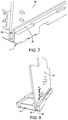
- FIGS. 7-9 illustrate the manner in which the PCBAs 56 are fitted within respective slots of the heat sink 14 to secure the PCBAs within the mounting bracket 12 of the mounting enclosure assembly 10 .
- the mounting enclosure assembly 10 further includes PCBA bonding material 66 disposed within the slot 54 of the heat sink 14 .
- this bonding material 66 is achieved by wrapping the edge 58 of the PCBA 56 with a thermal transfer material, such as a film or a thermal foam pad, e.g., 3M 5589H, or by filling the heat sink mounting slot 54 with a thermal compound paste, and then inserting the PCBA into the slot formed in the heat sink 14 .
- This bonding material 66 is press fit into the slot 54 of the heat sink 14 .
- FIGS. 8 and 9 show PCBA thermal transfer contact area of the heat sink 14 .
- FIG. 10 illustrates an alternate PCBA mounting solution, which, in one embodiment, includes a commercial retaining bracket 70 , such as a PCB-TainerTM provided by Birtcher Products of San Diego, Calif.
- a commercial retaining bracket 70 such as a PCB-TainerTM provided by Birtcher Products of San Diego, Calif.
- This solution requires the thermal bonding material 66 ; however, the retaining bracket 70 is attached to the heat sink 14 by suitable fasteners 72 , such as screws, rivets, and/or bolts/nuts, and the PCBA 56 is inserted in the retaining bracket.
- suitable fasteners 72 such as screws, rivets, and/or bolts/nuts
- the retaining bracket 70 may include beryllium copper retainers having a low-cost spring-action card retention design. The retainers attach to the heat sink using screws, rivets or adhesives and are designed primarily for use in sheet metal applications. The retainers provide protection against shock and vibration and offer excellent grounding characteristics.
- a method includes providing a mounting bracket and disposing a thermal bonding material within the slot of the body of the mounting bracket.
- the electronic component is positioned in the slot to secure the electronic component to the body of the mounting bracket within the slot.
- the mounting bracket is then secured to the mounting bracket onto the DIN rail.
- the thermal bonding material includes a flexible sheet that is wrapped along the edge of the electronic component.
- the flexible sheet can include a thermal foam pad.
- the thermal bonding material includes a thermal compound paste that is disposed within the slot prior to inserting the edge of the electronic substrate into the slot.
- An alternate embodiment may include constructing an entire rear surface of the enclosure out of the heat sink material or make the entire enclosure out of the heat sink material rather than integrating the heat sink into the enclosure plastic.
- An alternate design might construct the heat sinks out of a different type of material other than aluminum.
- An alternate design might shape the heat sinks differently, add airflow fins, change the contact points with the DIN rail, or even add thermal bonding material between the heat sink and the DIN rail contact point on the sub-panel chassis.
- heat sinks of the present disclosure produce heat sinks that are as efficient as heat sinks that are used with forced cooling.
- heat sinks produced in the manner disclosed herein are less expensive to make, and are more efficient.
- references to “or” may be construed as inclusive so that any terms described using “or” may indicate any of a single, more than one, and all of the described terms. Any references to front and back, left and right, top and bottom, upper and lower, and vertical and horizontal are intended for convenience of description, not to limit the present systems and methods or their components to any one positional or spatial orientation.
Abstract
Description
Claims (21)
Applications Claiming Priority (1)
| Application Number | Priority Date | Filing Date | Title |
|---|---|---|---|
| PCT/US2013/078241 WO2015102560A1 (en) | 2013-12-30 | 2013-12-30 | Method and apparatus for increasing heat dissipation capacity of a din rail mounted enclosure |
Related Parent Applications (1)
| Application Number | Title | Priority Date | Filing Date |
|---|---|---|---|
| PCT/US2013/078241 A-371-Of-International WO2015102560A1 (en) | 2013-12-30 | 2013-12-30 | Method and apparatus for increasing heat dissipation capacity of a din rail mounted enclosure |
Related Child Applications (1)
| Application Number | Title | Priority Date | Filing Date |
|---|---|---|---|
| US17/479,086 Division US20220007546A1 (en) | 2013-12-30 | 2021-09-20 | Apparatus for increasing heat dissipation capacity of a din rail mounted enclosure |
Publications (2)
| Publication Number | Publication Date |
|---|---|
| US20160330869A1 US20160330869A1 (en) | 2016-11-10 |
| US11178791B2 true US11178791B2 (en) | 2021-11-16 |
Family
ID=53493772
Family Applications (2)
| Application Number | Title | Priority Date | Filing Date |
|---|---|---|---|
| US15/107,681 Active 2036-08-30 US11178791B2 (en) | 2013-12-30 | 2013-12-30 | Apparatus for increasing heat dissipation capacity of a DIN rail mounted enclosure |
| US17/479,086 Pending US20220007546A1 (en) | 2013-12-30 | 2021-09-20 | Apparatus for increasing heat dissipation capacity of a din rail mounted enclosure |
Family Applications After (1)
| Application Number | Title | Priority Date | Filing Date |
|---|---|---|---|
| US17/479,086 Pending US20220007546A1 (en) | 2013-12-30 | 2021-09-20 | Apparatus for increasing heat dissipation capacity of a din rail mounted enclosure |
Country Status (4)
| Country | Link |
|---|---|
| US (2) | US11178791B2 (en) |
| EP (1) | EP3090611B8 (en) |
| CN (1) | CN105874895B (en) |
| WO (1) | WO2015102560A1 (en) |
Cited By (2)
| Publication number | Priority date | Publication date | Assignee | Title |
|---|---|---|---|---|
| US20210410323A1 (en) * | 2020-06-25 | 2021-12-30 | Phoenix Contact Gmbh & Co. Kg | Assembly with a heat sink core element forming a supporting structure |
| US20220256731A1 (en) * | 2019-01-09 | 2022-08-11 | Weidmüller Interface GmbH & Co. KG | Controler and modular control system of an industrial automation system |
Families Citing this family (13)
| Publication number | Priority date | Publication date | Assignee | Title |
|---|---|---|---|---|
| DE102013112115A1 (en) * | 2013-11-04 | 2015-05-07 | Phoenix Contact Gmbh & Co. Kg | Bridge module for a component assembly system |
| DE102013112117A1 (en) * | 2013-11-04 | 2015-05-07 | Phoenix Contact Gmbh & Co. Kg | Functional component for a component assembly system |
| KR102047500B1 (en) | 2014-11-27 | 2019-11-21 | 삼성전자주식회사 | System and method for providing to-do-list of user |
| USD855025S1 (en) * | 2017-02-23 | 2019-07-30 | Siemens Aktiengesellschaft | Switching device |
| USD839842S1 (en) * | 2017-03-20 | 2019-02-05 | Lsis Co., Ltd. | Digital motor protection relay |
| US10653022B2 (en) * | 2018-09-10 | 2020-05-12 | Caci, Inc.-Federal | Deployable hardened housing units |
| USD922365S1 (en) * | 2019-02-22 | 2021-06-15 | Ambit Microsystems (Shanghai) Ltd. | Smart gateway |
| USD916701S1 (en) * | 2019-03-25 | 2021-04-20 | Lsis Co., Ltd. | Gateway data logger |
| JP2021052155A (en) * | 2019-09-26 | 2021-04-01 | ファナック株式会社 | Electrical device including fan unit, and control panel including electrical device |
| JP2022147499A (en) * | 2021-03-23 | 2022-10-06 | パナソニックIpマネジメント株式会社 | Enclosure for electronic equipment |
| JP2022147498A (en) * | 2021-03-23 | 2022-10-06 | パナソニックIpマネジメント株式会社 | Enclosure for electronic equipment |
| DE102021120493A1 (en) * | 2021-08-06 | 2023-02-09 | Phoenix Contact Gmbh & Co. Kg | Electronics housing for mounting on a mounting rail and a system |
| BE1029900B1 (en) * | 2021-11-05 | 2023-06-05 | Phoenix Contact Gmbh & Co | Housing for accommodating an electrical heat source |
Citations (19)
| Publication number | Priority date | Publication date | Assignee | Title |
|---|---|---|---|---|
| EP0476322A1 (en) | 1990-09-10 | 1992-03-25 | Yokogawa Electric Corporation | Casing assembly for electronic equipment. |
| US5414593A (en) | 1992-12-24 | 1995-05-09 | Thomson-Csf | Electronic unit formed by two boards joined by assembling means |
| EP0740499A1 (en) | 1995-04-21 | 1996-10-30 | MAN Roland Druckmaschinen AG | Rail mounting of an equipment |
| JPH09162574A (en) | 1995-12-08 | 1997-06-20 | Keyence Corp | Electronic apparatus unit and electronic apparatus |
| US6563710B1 (en) | 1998-04-01 | 2003-05-13 | Omron Corporation | Electronic device, panel device, and supporting rail |
| US20050234681A1 (en) | 2004-04-20 | 2005-10-20 | National Instruments Corporation | Compact input measurement module |
| US20100128448A1 (en) * | 2008-11-25 | 2010-05-27 | Mettler-Toledo, Inc. | Mounting for industrial instrumentation |
| CN101763149A (en) | 2008-12-25 | 2010-06-30 | 研华股份有限公司 | Extensible industry computer system and host computer thereof |
| US20100232114A1 (en) | 2009-03-11 | 2010-09-16 | Square D Company | Solid state relay with internal heat sink |
| CN101865731A (en) | 2010-07-24 | 2010-10-20 | 永济新时速电机电器有限责任公司 | Novel temperature measurement electronic module |
| US7843691B2 (en) * | 2008-02-01 | 2010-11-30 | Telefonaktiebolaget L M Ericsson (Publ) | Techniques for cooling portable devices |
| US20100314522A1 (en) * | 2009-06-15 | 2010-12-16 | Rockwell Automation Technologies, Inc. | Integrated din rail attachment feature for superior attachment |
| US20110061591A1 (en) | 2009-09-17 | 2011-03-17 | Sciaky, Inc. | Electron beam layer manufacturing |
| US20110273844A1 (en) | 2010-05-05 | 2011-11-10 | Oscar Rivera Hernandez | Solid State Switching Device with Integral Heatsink |
| EP2551973A1 (en) * | 2011-07-28 | 2013-01-30 | ABB Technology AG | Clamping element |
| CN202930319U (en) | 2012-08-29 | 2013-05-08 | 安良电气有限公司 | Solid state relay |
| US20130188320A1 (en) * | 2012-01-24 | 2013-07-25 | General Electric Company | Mounting Base for Circuit Boards |
| US20130229775A1 (en) * | 2012-03-02 | 2013-09-05 | Dell Products L.P. | System and method for a convertible tower-to-rack enclosure |
| US20150168181A1 (en) * | 2013-12-18 | 2015-06-18 | General Electric Company | Systems and methods for displaying a probe gap value on a sensor system |
-
2013
- 2013-12-30 WO PCT/US2013/078241 patent/WO2015102560A1/en active Application Filing
- 2013-12-30 CN CN201380081933.1A patent/CN105874895B/en active Active
- 2013-12-30 EP EP13900733.0A patent/EP3090611B8/en active Active
- 2013-12-30 US US15/107,681 patent/US11178791B2/en active Active
-
2021
- 2021-09-20 US US17/479,086 patent/US20220007546A1/en active Pending
Patent Citations (19)
| Publication number | Priority date | Publication date | Assignee | Title |
|---|---|---|---|---|
| EP0476322A1 (en) | 1990-09-10 | 1992-03-25 | Yokogawa Electric Corporation | Casing assembly for electronic equipment. |
| US5414593A (en) | 1992-12-24 | 1995-05-09 | Thomson-Csf | Electronic unit formed by two boards joined by assembling means |
| EP0740499A1 (en) | 1995-04-21 | 1996-10-30 | MAN Roland Druckmaschinen AG | Rail mounting of an equipment |
| JPH09162574A (en) | 1995-12-08 | 1997-06-20 | Keyence Corp | Electronic apparatus unit and electronic apparatus |
| US6563710B1 (en) | 1998-04-01 | 2003-05-13 | Omron Corporation | Electronic device, panel device, and supporting rail |
| US20050234681A1 (en) | 2004-04-20 | 2005-10-20 | National Instruments Corporation | Compact input measurement module |
| US7843691B2 (en) * | 2008-02-01 | 2010-11-30 | Telefonaktiebolaget L M Ericsson (Publ) | Techniques for cooling portable devices |
| US20100128448A1 (en) * | 2008-11-25 | 2010-05-27 | Mettler-Toledo, Inc. | Mounting for industrial instrumentation |
| CN101763149A (en) | 2008-12-25 | 2010-06-30 | 研华股份有限公司 | Extensible industry computer system and host computer thereof |
| US20100232114A1 (en) | 2009-03-11 | 2010-09-16 | Square D Company | Solid state relay with internal heat sink |
| US20100314522A1 (en) * | 2009-06-15 | 2010-12-16 | Rockwell Automation Technologies, Inc. | Integrated din rail attachment feature for superior attachment |
| US20110061591A1 (en) | 2009-09-17 | 2011-03-17 | Sciaky, Inc. | Electron beam layer manufacturing |
| US20110273844A1 (en) | 2010-05-05 | 2011-11-10 | Oscar Rivera Hernandez | Solid State Switching Device with Integral Heatsink |
| CN101865731A (en) | 2010-07-24 | 2010-10-20 | 永济新时速电机电器有限责任公司 | Novel temperature measurement electronic module |
| EP2551973A1 (en) * | 2011-07-28 | 2013-01-30 | ABB Technology AG | Clamping element |
| US20130188320A1 (en) * | 2012-01-24 | 2013-07-25 | General Electric Company | Mounting Base for Circuit Boards |
| US20130229775A1 (en) * | 2012-03-02 | 2013-09-05 | Dell Products L.P. | System and method for a convertible tower-to-rack enclosure |
| CN202930319U (en) | 2012-08-29 | 2013-05-08 | 安良电气有限公司 | Solid state relay |
| US20150168181A1 (en) * | 2013-12-18 | 2015-06-18 | General Electric Company | Systems and methods for displaying a probe gap value on a sensor system |
Non-Patent Citations (2)
| Title |
|---|
| Extended European Search Report from corresponding European Application No. 13900733.0 dated Jul. 20, 2017. |
| Notification of transmittal of the International Search Report and the Written Opinion of the International Searching Authority from corresponding PCT/US2013/078241 dated Apr. 29, 2014. |
Cited By (2)
| Publication number | Priority date | Publication date | Assignee | Title |
|---|---|---|---|---|
| US20220256731A1 (en) * | 2019-01-09 | 2022-08-11 | Weidmüller Interface GmbH & Co. KG | Controler and modular control system of an industrial automation system |
| US20210410323A1 (en) * | 2020-06-25 | 2021-12-30 | Phoenix Contact Gmbh & Co. Kg | Assembly with a heat sink core element forming a supporting structure |
Also Published As
| Publication number | Publication date |
|---|---|
| EP3090611A1 (en) | 2016-11-09 |
| CN105874895B (en) | 2018-07-31 |
| US20160330869A1 (en) | 2016-11-10 |
| US20220007546A1 (en) | 2022-01-06 |
| WO2015102560A1 (en) | 2015-07-09 |
| CN105874895A (en) | 2016-08-17 |
| EP3090611A4 (en) | 2017-08-23 |
| EP3090611B1 (en) | 2020-08-19 |
| EP3090611B8 (en) | 2020-12-09 |
Similar Documents
| Publication | Publication Date | Title |
|---|---|---|
| US20220007546A1 (en) | Apparatus for increasing heat dissipation capacity of a din rail mounted enclosure | |
| EP2540148B1 (en) | Miniature multilayer radiative cooling case with hidden quick release snaps | |
| EP2887788B1 (en) | Electronics chassis and method of fabricating the same | |
| EP2961252B1 (en) | Systems and methods for passive cooling of components within electrical devices | |
| WO2008141170A1 (en) | Thermal management systems and methods for electronic components in a sealed enclosure | |
| US7796384B2 (en) | Hybrid chassis cooling system | |
| US9414524B2 (en) | Extended heat frame for printed circuit board | |
| US20140118954A1 (en) | Electronic device with heat-dissipating structure | |
| JP5698458B2 (en) | Electronic unit | |
| KR20160043050A (en) | Multi-layer heat spreader assembly with isolated convective fins | |
| EP3557964B1 (en) | Electronics cooling module | |
| US20180011522A1 (en) | Electronic device | |
| US20080266806A1 (en) | Electronic assembly that includes a heat sink which cools multiple electronic components | |
| US7551446B2 (en) | Thermal management device attachment | |
| RU170544U1 (en) | MODULAR ELECTRONIC DEVICE | |
| JP4269632B2 (en) | Electronic circuit module | |
| JP2015012004A (en) | Electronic device with heat sink | |
| CN210515131U (en) | Expansion module mounting frame and expansion module device with same | |
| CN209861420U (en) | Module power supply mounting structure | |
| CN215983314U (en) | Semiconductor refrigerating device and refrigerating electric appliance | |
| RU137635U1 (en) | ELECTRONIC MODULE IN THE HOUSING FOR CONDUCTIVE COOLING OF HEAT FUEL COMPONENTS | |
| US11844191B2 (en) | Apparatus for heat management in an electronic device | |
| CN114650709A (en) | Heat dissipation structure of chassis fan | |
| US20090143002A1 (en) | Computer system airflow optimization and configuration device | |
| CN102638955A (en) | Radiating device |
Legal Events
| Date | Code | Title | Description |
|---|---|---|---|
| AS | Assignment |
Owner name: SCHNEIDER ELECTRIC USA, INC., MASSACHUSETTS Free format text: ASSIGNMENT OF ASSIGNORS INTEREST;ASSIGNORS:WILLIAMS, JEFFREY SCOTT;MAYES, GARY LENN;FARRELL, MICHAEL JAMES;REEL/FRAME:039029/0964 Effective date: 20140205 |
|
| STPP | Information on status: patent application and granting procedure in general |
Free format text: DOCKETED NEW CASE - READY FOR EXAMINATION |
|
| STPP | Information on status: patent application and granting procedure in general |
Free format text: NON FINAL ACTION MAILED |
|
| STPP | Information on status: patent application and granting procedure in general |
Free format text: RESPONSE TO NON-FINAL OFFICE ACTION ENTERED AND FORWARDED TO EXAMINER |
|
| STPP | Information on status: patent application and granting procedure in general |
Free format text: FINAL REJECTION MAILED |
|
| STPP | Information on status: patent application and granting procedure in general |
Free format text: NON FINAL ACTION MAILED |
|
| STPP | Information on status: patent application and granting procedure in general |
Free format text: RESPONSE TO NON-FINAL OFFICE ACTION ENTERED AND FORWARDED TO EXAMINER |
|
| STPP | Information on status: patent application and granting procedure in general |
Free format text: FINAL REJECTION MAILED |
|
| STPP | Information on status: patent application and granting procedure in general |
Free format text: RESPONSE AFTER FINAL ACTION FORWARDED TO EXAMINER |
|
| STPP | Information on status: patent application and granting procedure in general |
Free format text: NOTICE OF ALLOWANCE MAILED -- APPLICATION RECEIVED IN OFFICE OF PUBLICATIONS |
|
| STPP | Information on status: patent application and granting procedure in general |
Free format text: PUBLICATIONS -- ISSUE FEE PAYMENT VERIFIED |
|
| STCF | Information on status: patent grant |
Free format text: PATENTED CASE |