JP2015012004A - Electronic device with heat sink - Google Patents
Electronic device with heat sink Download PDFInfo
- Publication number
- JP2015012004A JP2015012004A JP2013133766A JP2013133766A JP2015012004A JP 2015012004 A JP2015012004 A JP 2015012004A JP 2013133766 A JP2013133766 A JP 2013133766A JP 2013133766 A JP2013133766 A JP 2013133766A JP 2015012004 A JP2015012004 A JP 2015012004A
- Authority
- JP
- Japan
- Prior art keywords
- heat sink
- guide rail
- heat
- electronic
- fin
- Prior art date
- Legal status (The legal status is an assumption and is not a legal conclusion. Google has not performed a legal analysis and makes no representation as to the accuracy of the status listed.)
- Pending
Links
Images


Abstract
Description
ヒートシンクを備えた電子基板等の電子装置に関し、特に大型ヒートシンクの固定構造に関する。 The present invention relates to an electronic device such as an electronic substrate provided with a heat sink, and more particularly to a structure for fixing a large heat sink.
作動時の発熱量が高い発熱部品を有する電子基板については、図1に示すように、大型ヒートシンクを搭載する必要がある。こうした基板をサブラックのガイドレールに装填した場合には、ヒートシンクの質量によって、振動、重力等の負荷を受け、変形及び破損する可能性がある。そのため、ヒートシンク負荷を考慮した構造を採用することが必要である。
このような構造として、図2に示すように、基板の背面に補強部品を実装することでヒートシンク負荷による変形を低減させるものがある。しかし、補強部品の追加が必要となり、基板寸法や組立工程の増加を招く。また、ヒートシンクが大型になるほど負荷が増加するため、それに合わせて補強部品も大型化したり、多数設けることが必要となる。
As shown in FIG. 1, a large heat sink needs to be mounted on an electronic board having a heat generating component that generates a large amount of heat during operation. When such a substrate is loaded on a guide rail of a subrack, it may be deformed or damaged due to a load such as vibration or gravity due to the mass of the heat sink. Therefore, it is necessary to adopt a structure that takes into account the heat sink load.
As such a structure, as shown in FIG. 2, there is one that reduces deformation due to a heat sink load by mounting a reinforcing component on the back surface of the substrate. However, it is necessary to add a reinforcing component, resulting in an increase in board dimensions and assembly process. In addition, since the load increases as the heat sink becomes larger, it is necessary to increase the size of the reinforcing parts or to provide a large number of reinforcing parts accordingly.
この解決策として、特許文献1には、図3、図4に示すように、ヒートシンク1の荷重を、筐体(構造体)に設置されたガイドレール3により支持することで、コネクタへ荷重が負荷されることを防止することが示されている。このような構造によれば、ヒートシンク1の負荷は構造体が支えるため、基板への負荷が発生せず、基板の補強部品は不要となり、ヒートシンクが大型化した場合でも基板への負荷は増加しない。
As a solution to this problem, as shown in FIGS. 3 and 4,
しかし、図3に示される支持構造は、ガイドレール3が、ヒートシンクの上端及び下端において、フィンの高さ方向全体を覆うよう支持するものであり、上端、下端においては、フィンがガイドレール3に対し平行に配置することになり、フィンを水平あるいは傾斜して横向きとなるような実装のみに限定され、フィンから放熱に伴う上向きの対流による自然空冷を利用することができない。
仮にフィンが縦向きとなるような実装に適用した場合、ガイドレール3が、フィン上下端でフィンの長手方向に対し直交する方向で塞ぐため、フィンからの放熱による対流を妨げて放熱性能が著しく低下する。すなわち、特許文献1に示される構造は、冷却ファンを用いてフィンの表面に沿って冷却風を強制的に送風する強制空冷ヒートシンクを前提としているものであり、フィンは、その長手方向を送風方向に沿うよう配置されればよく、フィン自体もガイドレールで覆われる程度の長さ(ベースからフィン先端までの寸法)でも、冷却ファンの容量や回転数を増加させることで、所望の冷却を行うことを前提としている。
However, in the support structure shown in FIG. 3, the
If it is applied to mounting in which the fins are vertically oriented, the
しかし、強制空冷ヒートシンクは、冷却ファンを駆動する電動モータを始め、送風を行うための機器が必要となり、コストアップ、スペース増、消費電力の増加を招くばかりでなく、例えば、鉄道車両に搭載された場合、架線事故等により電源が突然遮断された際には、発熱部品が過熱し損傷を招くおそれがある。したがって、特に、鉄道車両に搭載される電子基板に関しては、フィンに沿う対流を利用した自然空冷で必要な冷却容量を確保することが好ましいが、特許文献1に示される構造では困難である。
However, forced air-cooled heat sinks require equipment for blowing air, including an electric motor that drives a cooling fan, which not only increases costs, increases space, and increases power consumption. In such a case, when the power supply is suddenly shut down due to an overhead line accident or the like, the heat generating parts may overheat and cause damage. Therefore, in particular, regarding an electronic board mounted on a railway vehicle, it is preferable to secure a necessary cooling capacity by natural air cooling using convection along fins, but the structure shown in
また、特許文献1には、ヒートシンクの構造体への固定手段として、図3に示されるように、ヒートシンク1を直接構造体に固定する態様と、図4に示されるように、ヒートシンク1と構造体との間に固定用部材4を設けることで、ヒートシンクと構造体を間接的に固定する態様とが提案されている。両者を比較した場合、以下の理由によって前者のほうがヒートシンクの固有振動数を上昇させることができ、振動に強い構造とすることができる。
Further, in
例えば、ヒートシンク固定部を構造体に直接固定する場合、ヒートシンク中央の固有振動数ω1は、ヒートシンク質量mと、ヒートシンク中央からヒートシンク固定部(=構造体)までのバネ定数k1より、以下のように与えられる。
ω1=(k1/m)1/2
For example, when directly fixing the heat sink fixing portion to the structure, the natural frequency ω 1 at the center of the heat sink is expressed by the following from the heat sink mass m and the spring constant k 1 from the heat sink center to the heat sink fixing portion (= structure): As given.
ω 1 = (k 1 / m) 1/2
次に、ヒートシンク固定部と構造体の間にバネ定数k2を持つ固定用部材を挿入した場合、ヒートシンク中央から構造体までのバネ定数k12は、k1及びk2を直列に結合した値となるため、以下のようになる。
k12=(k1・k2)/(k1+k2)<k1
また、このときの固有振動数ω12は、次のように求めることができる。
ω12=(k12/m)1/2
Next, when a fixing member having a spring constant k 2 is inserted between the heat sink fixing portion and the structure, the spring constant k 12 from the center of the heat sink to the structure is a value obtained by coupling k 1 and k 2 in series. Therefore, it becomes as follows.
k 12 = (k 1 · k 2 ) / (k 1 + k 2 ) <k 1
Further, the natural frequency ω 12 at this time can be obtained as follows.
ω 12 = (k 12 / m) 1/2
ここで、ω1とω12を比較すると、k12<k1であることからω12<ω1となり、ヒートシンクと構造体を直接固定する構造の方が、固有振動数が高くなる。すなわち、振動に強い構造とすることができる。逆に、ヒートシンクと構造体の間に直列に実装される固定用部材が増加するほど、振動に弱い構造となる。すなわち、前述の理由からヒートシンクは直接構造体に固定することが望ましい。
そのため、図4の構造では、図3の構造と同様、対流を利用した自然空冷により十分な冷却能力が得られないばかりでなく、固有振動数を低下させ、振動に弱い構造となってしまう。
Here, when ω 1 and ω 12 are compared, since k 12 <k 1 , ω 12 <ω 1 , and the natural frequency is higher in the structure in which the heat sink and the structure are directly fixed. That is, a structure resistant to vibration can be obtained. Conversely, as the number of fixing members mounted in series between the heat sink and the structure increases, the structure is more susceptible to vibration. That is, it is desirable to fix the heat sink directly to the structure for the reasons described above.
Therefore, in the structure of FIG. 4, as in the structure of FIG. 3, not only sufficient cooling capacity cannot be obtained by natural air cooling using convection, but also the natural frequency is lowered and the structure is weak against vibration.
そこで、本発明の目的は、強制空冷ヒートシンクを利用することなく、対流を利用した自然空冷でも、電子基板の冷却性能を低下させず、しかも、追加部品を必要とせずにヒートシンクの重量が基板に負荷されないようにするとともに、固有振動数を上昇させて、耐振動性の高い構造を提供することを目的としている。 Therefore, an object of the present invention is to reduce the cooling performance of the electronic board without using a forced air-cooled heat sink, even with natural air cooling using convection, and the weight of the heat sink does not require additional components. The object is to provide a structure with high vibration resistance by preventing the load and increasing the natural frequency.
上記課題を解決するために、例えば特許請求の範囲に記載の構成を採用する。本願は上記課題を解決する手段を複数含んでいるが、その一例を挙げるならば、本発明のヒートシンクを備えた電子装置においては、ベースと該ベースに対し略垂直方向に延出するフィンを備えたヒートシンクと、該ヒートシンクに装着され、発熱部品の発熱を前記ヒートシンクを介して放熱する電子基板と、前記電子基板及びヒートシンクを格納する構造体とを備え、前記ヒートシンクを前記構造体に支持させるとともに、前記フィン間に対流方向の流路空隙を形成する固定構造を具備するようにした。 In order to solve the above problems, for example, the configuration described in the claims is adopted. The present application includes a plurality of means for solving the above-described problems. For example, in an electronic device including a heat sink according to the present invention, a base and a fin extending in a direction substantially perpendicular to the base are provided. A heat sink, an electronic board mounted on the heat sink and dissipating heat from the heat-generating component via the heat sink, and a structure for storing the electronic board and the heat sink, and supporting the heat sink to the structure. A fixing structure for forming a flow passage gap in the convection direction between the fins is provided.
また、上記のヒートシンクを備えた電子装置において、前記構造体の上下に前記ヒートシンクを支持するガイドレールを設けるとともに、前記ヒートシンクに前記ガイドレールと結合する結合部を設け、前記ヒートシンクを前記ベースと平行に誘導して、前記構造体に格納するようにした。 Further, in the electronic device including the heat sink, a guide rail that supports the heat sink is provided above and below the structure, and a coupling portion that is coupled to the guide rail is provided on the heat sink, and the heat sink is parallel to the base. To be stored in the structure.
本発明の電子装置によれば、ヒートシンクを追加部品を必要とせずに、直接ガイドレールや筐体などの構造体に固定することができ、電子基板にヒートシンクの負荷が掛からないようにすることができる。また、ヒートシンクを直接構造体に固定することで、固定用部材を介して間接的にヒートシンクを構造体に固定する場合と比較して、剛性が増加し固有振動数が上昇するために振動に強くなる。さらに、ヒートシンクと構造体との固定部を増やすことで、より固有振動数を上昇させることができる。
また、自然空冷ヒートシンクでは、一般的にフィンの長さ(ベースからフィン先端までの寸法)を十分に確保することが必要であることから、これを利用し、フィンにガイドレールとの結合部を設けてフィンを構造体に固定することで、ヒートシンクと構造体との固定点を増加させ、固有振動数をさらに上昇させ、振動に強い構造とすることができる。
According to the electronic device of the present invention, the heat sink can be directly fixed to a structure such as a guide rail or a housing without the need for additional components, and the load of the heat sink is not applied to the electronic board. it can. In addition, by fixing the heat sink directly to the structure, the rigidity is increased and the natural frequency is increased compared to the case where the heat sink is indirectly fixed to the structure through a fixing member, so that it is resistant to vibration. Become. Furthermore, the natural frequency can be further increased by increasing the number of fixing portions between the heat sink and the structure.
In addition, in natural air-cooled heat sinks, it is generally necessary to ensure a sufficient length of the fin (dimension from the base to the tip of the fin), so this can be used to connect the guide rail to the fin. By providing and fixing the fin to the structure, the fixing point between the heat sink and the structure can be increased, the natural frequency can be further increased, and a structure resistant to vibration can be obtained.
また、ガイドレール、ガイドレールとの結合部は適宜設計可能であり、幅を縮小することができるため、縦置きヒートシンクの上下にレールを設置しても対流を塞ぐことがなく、自然空冷効果を最大限に高めることができる。特に、レールを熱伝導率の高い金属で形成した場合、ヒートシンクの熱がガイドレールを経由してサブラック等の構造体に伝導するため、ヒートシンクの放熱性能を向上することができる。 In addition, the guide rail and the connecting portion with the guide rail can be designed as appropriate, and the width can be reduced, so even if rails are installed above and below the vertical heat sink, convection is not blocked and natural air cooling effect is achieved. Can be maximized. In particular, when the rail is formed of a metal having high thermal conductivity, the heat of the heat sink is conducted to the structure such as the subrack via the guide rail, so that the heat dissipation performance of the heat sink can be improved.
しかも、ヒートシンクが備える固定部を、ガイドレールに挿入可能な構造とすることで、ガイドレールを備えたサブラック(もしくはレールを備えたバックプレーン)に挿入して搭載するような、ヒートシンク実装基板に対して、搭載と同時にヒートシンクが直接ガイドレールに固定される構造となり、容易に上述の固定構造及び効果が実現可能となる。
上記した以外の課題、構成及び効果は、以下の実施形態の説明により明らかにされる。
In addition, by adopting a structure that allows the fixed part of the heat sink to be inserted into the guide rail, it can be mounted on a heat sink mounting board that is inserted and mounted on a subrack (or a backplane with a rail) equipped with a guide rail. On the other hand, the heat sink is directly fixed to the guide rail simultaneously with the mounting, and the above-described fixing structure and effects can be easily realized.
Problems, configurations, and effects other than those described above will be clarified by the following description of embodiments.
以下、図面を参照して本発明の実施形態について説明する。 Hereinafter, embodiments of the present invention will be described with reference to the drawings.
[実施例1]
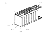
図5〜図7は、本発明に係るヒートシンクを備えた電子装置の実施例1を示すもので、図5は、ヒートシンクの各フィンと、構造体としてのガイドレールとの関係を示す斜視図、図6は上面図、図7は前面図をそれぞれ示している。
なお、本実施例は、例えば、鉄道車両など、特に振動の大きい移動体に搭載される電子装置へ適用することで高い効果が得られるものである。こうした移動体においては、ATC用車上装置に代表されるように、数多くの電子部品が搭載されており、例えば、電源部、送信部、受信部、外部接続部といった機能毎に区分けされた電子部品が、規格化されたサイズの電子基板上に搭載されている。こうした電子基板類を、やはり規格化された、構造体としてのサブラックに装着されたガイドレールに差し込んで挿入することで装填し、相互に接続することにより車上装置の送受信部を構成するのが一般的である。
[Example 1]
5 to 7 show Example 1 of an electronic device including a heat sink according to the present invention, and FIG. 5 is a perspective view showing a relationship between each fin of the heat sink and a guide rail as a structure. 6 shows a top view, and FIG. 7 shows a front view.
In addition, a high effect is acquired by applying a present Example to the electronic device mounted in the mobile body with especially large vibrations, such as a rail vehicle, for example. In such a moving body, a large number of electronic components are mounted as typified by the on-board device for ATC. For example, an electronic device divided into functions such as a power supply unit, a transmission unit, a reception unit, and an external connection unit. The component is mounted on a standardized size electronic board. These electronic boards are loaded by inserting them into a standardized guide rail mounted on a subrack as a structure, and they are connected to each other to constitute a transmission / reception unit of an on-board device. Is common.
本実施例では、電子基板をサブラックのガイドレールに差し込むのに代えて、電子基板に装着されたヒートシンクをガイドレールで支持するようにした。
具体的には、図6に示すように、こうした基板類のうち、例えば、送信部のように、発熱量の高い発熱部品202を搭載する電子基板200には、ヒートシンク210が装着される。ヒートシンク210は、アルミニウム等の軽量で熱伝達率の高い素材で成型されたもので、電子基板200に直交する方向に延びるフィン212、及び電子基板に略平行なベース211から構成され、ベース211に発熱部品202が装着されることで、発熱部品202で発生した熱量がベース212を介してフィン212に伝達され、外気に放熱する機能を有している。
In this embodiment, instead of inserting the electronic board into the guide rail of the subrack, the heat sink mounted on the electronic board is supported by the guide rail.
Specifically, as shown in FIG. 6, a
この実施例では、図7に示すように、各フィン212及びベース211の上下端に、ベース211に略平行な基板挿入方向に、直線上に整列するよう、レール挿入部213a〜213cをそれぞれ備えている。
これらのレール挿入部213a〜213cは、サブラック220に奥行き方向に取り付けられたガイドレール230a〜230cの凹部にそれぞれ嵌合して結合される。
すなわち、ベース211の上下端面に形成されたレール挿入部213aは、基板挿入方向、すなわち電子基板200と平行に延びており、ガイドレール230aの凹部に嵌合するよう挿入されて結合される。
同様に、各フィン212の上下端面から延びるレール挿入部213b、213cも、電子基板200と平行に整列しており、それぞれガイドレール230b、230cの凹部に挿入されて結合される。
In this embodiment, as shown in FIG. 7, rail insertion portions 213 a to 213 c are respectively provided at the upper and lower ends of the
These rail insertion portions 213a to 213c are respectively fitted and coupled to concave portions of guide rails 230a to 230c attached to the sub-rack 220 in the depth direction.
In other words, the rail insertion portions 213a formed on the upper and lower end surfaces of the base 211 extend in parallel with the board insertion direction, that is, the
Similarly, rail insertion portions 213b and 213c extending from the upper and lower end surfaces of the
ガイドレール230の幅は、フィン212の長さ(ベースからフィン先端までの寸法)と比較してもできるだけ小さくするとともに、各ガイドレール間の距離は、対流が円滑に行われる程度の距離を確保して配置されている。また、図6に示されるように、この実施例では、サブラック220の上面及び下面はともに外気に開放されていることから、ガイドレール230が対流を塞ぐことない。このため、ヒートシンク210のフィン212からの放熱により発生する上昇気流が妨げられることはなく、サブラック220の下面から導入された外気が、フィン212と効率よく熱交換を行い、サブラック220の上面から円滑に排出されることで、フィン212の長手方向に沿う対流によりヒートシンク210の放熱性能を確保することができる。
The width of the
本実施例によれば、ヒートシンク210に形成されたレール挿入部213a〜213cが、サブラック220に装着されているガイドレール230に固定されることで、電子基板200には、ヒートシンク210の重量がなんら負荷されない構造となる。
また、本実施例では、レール挿入部213aにより、ベース211をガイドレール230aで固定するのに加え、フィン212にもガイドレール230b、230cへの固定点を設けることで、ヒートシンク210の固定可能箇所を増加することができる。また、フィン212の長さが大きいヒートシンク210を搭載する場合においても、フィン212が長い分、レール230の実装可能数を増加することができるため、ヒートシンク210の固定点を増加し、固定強度を維持可能となる。さらに、固定点が増加する場合、以下の理由によって固有振動数が上昇するため、振動強度が向上する。
According to the present embodiment, the rail insertion portions 213a to 213c formed in the
In the present embodiment, in addition to fixing the base 211 with the guide rail 230a by the rail insertion portion 213a, the
仮に、質量mのヒートシンクが固定点P1で構造体に固定される場合、ヒートシンク中央の固有振動数ω1は、ヒートシンク中央から構造体(固定部P1)までのバネ係数k1によって以下のように与えられる。
ω1=(k1/m)1/2
次に、ヒートシンクが固定点P2を追加した場合、ヒートシンク中央からP2までのバネ係数をk2とすると、ヒートシンク中央から構造体までのバネ係数k12は、k1及びk2を並列に結合することで、以下のように与えられる。
k12=k1+k2
よって、前記固有振動数の式より、ヒートシンクがP1及びP2で固定された場合のヒートシンク中央の固有振動数ω12は以下となる。
ω12=(k12/m)1/2=((k1+k2)/m)1/2>ω1
If the heat sink with mass m is fixed to the structure at the fixing point P 1 , the natural frequency ω 1 at the center of the heat sink is represented by the following spring coefficient k 1 from the center of the heat sink to the structure (fixed part P 1 ). As given.
ω 1 = (k 1 / m) 1/2
Then, if the heat sink has added fixed point P 2, the spring coefficient of the middle of the heat sink to P 2 When k 2, the spring coefficient k 12 from the heat sink center to structure, the k 1 and k 2 in parallel By combining, it is given as follows.
k 12 = k 1 + k 2
Therefore, from the natural frequency equation, the natural frequency ω 12 at the center of the heat sink when the heat sink is fixed at P 1 and P 2 is as follows.
ω 12 = (k 12 / m) 1/2 = ((k 1 + k 2 ) / m) 1/2 > ω 1
すなわち、P1のみで固定した場合と比較して、P1及びP2で固定した場合の方が、固有振動数が高いことが分かる。また、固定点を増加させるほど、ヒートシンク中央から構造体までのバネ係数が増加するため、固有振動数が上昇する。固有振動数が高いことは、すなわちヒートシンクが共振する周波数が高いことであり、振動に強いことを意味する。よって、ヒートシンクの固定点が多いほど振動に強い固定構造であることが分かる。
なお、固定点の数や位置は任意に設計可能であるため、例えば、図8に示すように、上方で1点、下方で2点のように、上下の固定点数を変えるなど、条件ごとに最適な設計とすることができる。
That is, it can be seen that the natural frequency is higher in the case of fixing with P 1 and P 2 than in the case of fixing with P 1 alone. Further, as the fixed point is increased, the natural coefficient increases because the spring coefficient from the center of the heat sink to the structure increases. A high natural frequency means that the frequency at which the heat sink resonates is high, which means it is resistant to vibration. Therefore, it can be seen that the more the heat sink fixing points, the stronger the fixing structure.
Since the number and position of the fixed points can be arbitrarily designed, for example, as shown in FIG. 8, the number of fixed points at the top and bottom is changed, such as one point at the top and two points at the bottom. Optimal design can be achieved.
また、本実施形態では、ヒートシンク210の上下を、構造体としてのガイドレール230に直接固定する固定構造であるため、固定のための追加部品が不要であり、かつ、電子基板200及びヒートシンク210の寸法を増大させずに固定可能となる。
さらに、フィン212の上下のみで固定する場合、ヒートシンク210の電子基板200側にガイドレール230の淵が突出することがないため、電子基板200とガイドレール230との干渉がなくなり、特許文献1のように電子基板200をヒートシンク210より小さくする必要がなくなる。
In this embodiment, since the upper and lower sides of the
Furthermore, when fixing only by the upper and lower sides of the
特に、規格化されたサブラックシステム(例えば、19インチラックシステム)に本実施形態を適用する場合、レール挿入部213の幅を、やはり規格化された電子基板の厚さ(例えば、1.6mm)と同じ寸法とすることで、ガイドレール230に電子基板を挿入するための規格化されたガイドレールを使用することができる。このガイドレールは標準化されているために安価で容易に入手可能であるため、ガイドレール230を個別に設計、製造する必要がなくなり、製造コストを削減することができる。
In particular, when this embodiment is applied to a standardized subrack system (for example, a 19-inch rack system), the width of the
図7に示されるように、サブラック220にはバックプレーン221と、ガイドレール230が固定されている。電子基板200は、発熱部品202に加え、コネクタ201を搭載し、レール挿入部213を備えたヒートシンク210には、発熱部品202と接触するように電子基板200が搭載される。ヒートシンク210は、レール挿入部213a〜cをガイドレール230a〜cに挿入することで、バックプレーン221に誘導され、コネクタ201をバックプレーン221に接続する。
また、サブラック220は、フロントパネル222(図6参照)を備えており、フロントパネル222は、電子基板200をサブラック220に搭載することにより、サブラック220の電子基板200挿入口を塞ぎ、サブラック220に固定される。また、ヒートシンク210は、フロントパネル222により固定されており、それによって、サブラック220と間接的に固定されている。
さらに、ヒートシンク210をバックプレーン221と固定してもよい。ヒートシンク210をフロントパネル222及びバックプレーン221に固定することで、ヒートシンク210はレールの長手方向への振動に対する強度が向上する。
As shown in FIG. 7, a backplane 221 and a
The sub-rack 220 includes a front panel 222 (see FIG. 6). The
Further, the
[実施例2]
図9に示す実施例では、電子基板300に搭載されるヒートシンク310は、フィン312全体をレール330に挿入されることで固定される。すなわち、ガイドレール330の幅は、ヒートシンク310のフィン312を長さ方向に覆うように設定されており、上下面に通気口331が形成されている。
これにより、ヒートシンク310が熱せられてフィン312の間に対流が発生した場合においても、ガイドレール330が対流を塞ぐことなく、ヒートシンク310の放熱性能を確保可能となっている。
なお、図10に示すように、ガイドレールを設けることなく、サブラック320に直接支持させ、ヒートシンク310の上端、下端において、左右(フィン312の先端とベース311の背面)を固定部340で支持する構造としてもよい。
[Example 2]
In the embodiment shown in FIG. 9, the
Thereby, even when the
As shown in FIG. 10, without providing the guide rail, the sub-rack 320 is directly supported, and the left and right (the tip of the
さらに、図11に示すように、フィン321の中央部付近に凹部を形成し、挿入方向に形成した固定部340に嵌合するようにしてもよい。また、図12に示すように、固定部340をL字型として、ヒートシンク310の上端、下端において、左右を支持するようにしてもよい。
これらの固定部340は、電子基板300に搭載されるヒートシンク310の挿入方向に連続的に設けてもよく、断続的に設けてもよい。
本実施例によれば、ヒートシンク310をサブラック320に装填する際は、上下にレール挿入部を設けるための加工が不要となるため、ヒートシンク310の製造コストが減少する。
Furthermore, as shown in FIG. 11, a recess may be formed near the center of the fin 321 and may be fitted to a fixing
These fixing
According to the present embodiment, when the
[実施例3]
図13は、ヒートシンク310の上下をサブラック320で直接支持し、ヒートシンク310にレール挿入用部品350を連結し、電子基板300の上下を挟むようにした例である。本実施例によれば、サブラック320に装填する際には、レール挿入用部品350の上下に形成したレール挿入部を、対応するガイドレール330に嵌合させて挿入すればよく、フィンやベースにレール挿入部加工が不要となる。また、レール挿入用部品350を電磁シールド効果のある材質で形成することで、電磁ノイズの放射を抑制することもできる。
[Example 3]
FIG. 13 shows an example in which the upper and lower sides of the
[実施例4]
図14は、ヒートシンク310に形成したレール挿入部、ガイドレール330に形成した凹部を、三角形状に接触させるようにした例である。本実施例によれば、ヒートシンク310に形成したレール挿入部とガイドレール330との接触部の角度が大きくなり、接触面積も増大できるため、接合部の応力集中が軽減でき、強度が向上する。また、レール挿入部を三角形とすることで、レール挿入部の寸法精度が低い場合においても、高い位置精度で実装することが可能となる。
両者の接触形状は、三角形に限らず、円形、あるいは、ガイドレールの両外側に密着するような凹型等、ヒートシンク310の形態に応じて、様々なものを採用することができる。また、ヒートシンク310に形成したレール挿入部とガイドレール330との接触部の両方、あるいはいずれか一方に、自己潤滑性樹脂等の樹脂皮膜を形成しておくと、サブラック320への挿入を円滑にするとともに、固有振動数を高めることができる。
[Example 4]
FIG. 14 shows an example in which the rail insertion portion formed in the
The contact shape of both is not limited to a triangle, and various shapes can be adopted depending on the form of the
本発明は上記した実施例に限定されるものではなく、様々な変形例が含まれる。例えば、上記した実施例は本発明を分かりやすく説明するために詳細に説明したものであり、必ずしも説明した全ての構成を備えるものに限定されるものではない。また、ある実施例の構成の一部を他の実施例の構成に置き換えることが可能であり、また、ある実施例の構成に他の実施例の構成を加えることも可能である。また、各実施例の構成の一部について、他の構成の追加・削除・置換をすることが可能である。 The present invention is not limited to the above-described embodiments, and includes various modifications. For example, the above-described embodiments have been described in detail for easy understanding of the present invention, and are not necessarily limited to those having all the configurations described. Further, a part of the configuration of one embodiment can be replaced with the configuration of another embodiment, and the configuration of another embodiment can be added to the configuration of one embodiment. Further, it is possible to add, delete, and replace other configurations for a part of the configuration of each embodiment.
100 電子基板
110 ヒートシンク
111 ベース
112 フィン
113 レール挿入部
130 レール
200 電子基板
201 コネクタ
202 発熱部品
210 ヒートシンク
212 フィン
213 レール挿入部
220 サブラック
221 バックプレーン
222 フロントパネル
230 ガイドレール
300 電子基板
310 ヒートシンク
330 レール
331 通気口
340 固定部
100 Electronic board 110 Heat sink 111 Base 112 Fin 113 Rail insertion part 130
Claims (4)
前記ヒートシンクを前記構造体に支持させるとともに、前記フィン間に対流方向の流路空隙を形成する固定構造を具備することを特徴とするヒートシンクを備えた電子装置。 A heat sink having a base and a fin extending in a direction substantially perpendicular to the base, an electronic board mounted on the heat sink and dissipating heat generated by the heat-generating component via the heat sink, and the electronic board and the heat sink are stored. With a structure,
An electronic apparatus comprising a heat sink, comprising: a fixing structure that supports the heat sink on the structure and that forms a flow passage gap in a convection direction between the fins.
Priority Applications (1)
| Application Number | Priority Date | Filing Date | Title |
|---|---|---|---|
| JP2013133766A JP2015012004A (en) | 2013-06-26 | 2013-06-26 | Electronic device with heat sink |
Applications Claiming Priority (1)
| Application Number | Priority Date | Filing Date | Title |
|---|---|---|---|
| JP2013133766A JP2015012004A (en) | 2013-06-26 | 2013-06-26 | Electronic device with heat sink |
Publications (1)
| Publication Number | Publication Date |
|---|---|
| JP2015012004A true JP2015012004A (en) | 2015-01-19 |
Family
ID=52304953
Family Applications (1)
| Application Number | Title | Priority Date | Filing Date |
|---|---|---|---|
| JP2013133766A Pending JP2015012004A (en) | 2013-06-26 | 2013-06-26 | Electronic device with heat sink |
Country Status (1)
| Country | Link |
|---|---|
| JP (1) | JP2015012004A (en) |
Cited By (2)
| Publication number | Priority date | Publication date | Assignee | Title |
|---|---|---|---|---|
| CN106804100A (en) * | 2015-11-26 | 2017-06-06 | 英业达科技有限公司 | Radiator positioner |
| CN109275301A (en) * | 2018-11-28 | 2019-01-25 | 王付华 | A kind of newly-designed 19 inches of plug-in card cabinets |
Citations (3)
| Publication number | Priority date | Publication date | Assignee | Title |
|---|---|---|---|---|
| JPH10117077A (en) * | 1996-10-11 | 1998-05-06 | Fujikura Ltd | Heat sink |
| JP3057411U (en) * | 1998-06-29 | 1999-06-02 | 奇▲宏▼股▲ふん▼有限公司 | Mounting device for no-package type CPU board |
| JP2007134471A (en) * | 2005-11-10 | 2007-05-31 | Fuji Electric Systems Co Ltd | Power converter for railway coach |
-
2013
- 2013-06-26 JP JP2013133766A patent/JP2015012004A/en active Pending
Patent Citations (3)
| Publication number | Priority date | Publication date | Assignee | Title |
|---|---|---|---|---|
| JPH10117077A (en) * | 1996-10-11 | 1998-05-06 | Fujikura Ltd | Heat sink |
| JP3057411U (en) * | 1998-06-29 | 1999-06-02 | 奇▲宏▼股▲ふん▼有限公司 | Mounting device for no-package type CPU board |
| JP2007134471A (en) * | 2005-11-10 | 2007-05-31 | Fuji Electric Systems Co Ltd | Power converter for railway coach |
Cited By (2)
| Publication number | Priority date | Publication date | Assignee | Title |
|---|---|---|---|---|
| CN106804100A (en) * | 2015-11-26 | 2017-06-06 | 英业达科技有限公司 | Radiator positioner |
| CN109275301A (en) * | 2018-11-28 | 2019-01-25 | 王付华 | A kind of newly-designed 19 inches of plug-in card cabinets |
Similar Documents
| Publication | Publication Date | Title |
|---|---|---|
| US20220007546A1 (en) | Apparatus for increasing heat dissipation capacity of a din rail mounted enclosure | |
| US20080278912A1 (en) | Thermal management systems and methods for electronic components in a sealed enclosure | |
| EP2887788B1 (en) | Electronics chassis and method of fabricating the same | |
| US7974093B2 (en) | Open frame electronic chassis for enclosed modules | |
| EP2961252B1 (en) | Systems and methods for passive cooling of components within electrical devices | |
| TWI722195B (en) | Electronic device and heat radiation structure of electronic device | |
| US9578781B2 (en) | Heat management for electronic enclosures | |
| CN108697030B (en) | Electronic device for a motor vehicle | |
| JP2012023329A (en) | Substrate unit and electronic device | |
| US10455741B2 (en) | Rack enclosure with perforations for cooling | |
| JP6337547B2 (en) | Electronic equipment housing | |
| US9414524B2 (en) | Extended heat frame for printed circuit board | |
| WO2021038954A1 (en) | Electrical device and electronic control device | |
| JP2015012004A (en) | Electronic device with heat sink | |
| JP2006506808A (en) | Housing for electronic circuits and components | |
| JP3983496B2 (en) | Transmission amplification unit for wireless communication device | |
| JP2012164743A (en) | On-vehicle electronic apparatus | |
| JP2012089594A (en) | On-vehicle electronic apparatus | |
| CN104981132A (en) | Dummy handle bar | |
| JP2015011045A (en) | Cooling structure of display device | |
| JP7309454B2 (en) | Electronic units and electronic equipment | |
| JP5717676B2 (en) | Heat dissipation structure of electronic equipment | |
| JP2017162892A (en) | Electronic device housing | |
| JP5347638B2 (en) | Subrack structure and rack structure | |
| JP2023080447A (en) | Electronic control device |
Legal Events
| Date | Code | Title | Description |
|---|---|---|---|
| A621 | Written request for application examination |
Free format text: JAPANESE INTERMEDIATE CODE: A621 Effective date: 20160203 |
|
| A977 | Report on retrieval |
Free format text: JAPANESE INTERMEDIATE CODE: A971007 Effective date: 20161020 |
|
| A131 | Notification of reasons for refusal |
Free format text: JAPANESE INTERMEDIATE CODE: A131 Effective date: 20161025 |
|
| A02 | Decision of refusal |
Free format text: JAPANESE INTERMEDIATE CODE: A02 Effective date: 20170418 |