US11166319B2 - Performing a two-step random access channel procedure - Google Patents
Performing a two-step random access channel procedure Download PDFInfo
- Publication number
- US11166319B2 US11166319B2 US16/584,249 US201916584249A US11166319B2 US 11166319 B2 US11166319 B2 US 11166319B2 US 201916584249 A US201916584249 A US 201916584249A US 11166319 B2 US11166319 B2 US 11166319B2
- Authority
- US
- United States
- Prior art keywords
- random access
- access channel
- step random
- channel procedure
- procedure
- Prior art date
- Legal status (The legal status is an assumption and is not a legal conclusion. Google has not performed a legal analysis and makes no representation as to the accuracy of the status listed.)
- Active
Links
Images


Classifications
-
- H—ELECTRICITY
- H04—ELECTRIC COMMUNICATION TECHNIQUE
- H04W—WIRELESS COMMUNICATION NETWORKS
- H04W76/00—Connection management
- H04W76/10—Connection setup
- H04W76/11—Allocation or use of connection identifiers
-
- H—ELECTRICITY
- H04—ELECTRIC COMMUNICATION TECHNIQUE
- H04L—TRANSMISSION OF DIGITAL INFORMATION, e.g. TELEGRAPHIC COMMUNICATION
- H04L5/00—Arrangements affording multiple use of the transmission path
- H04L5/0091—Signalling for the administration of the divided path, e.g. signalling of configuration information
- H04L5/0094—Indication of how sub-channels of the path are allocated
-
- H—ELECTRICITY
- H04—ELECTRIC COMMUNICATION TECHNIQUE
- H04W—WIRELESS COMMUNICATION NETWORKS
- H04W72/00—Local resource management
- H04W72/04—Wireless resource allocation
- H04W72/044—Wireless resource allocation based on the type of the allocated resource
- H04W72/0446—Resources in time domain, e.g. slots or frames
-
- H—ELECTRICITY
- H04—ELECTRIC COMMUNICATION TECHNIQUE
- H04W—WIRELESS COMMUNICATION NETWORKS
- H04W74/00—Wireless channel access
- H04W74/002—Transmission of channel access control information
- H04W74/004—Transmission of channel access control information in the uplink, i.e. towards network
-
- H—ELECTRICITY
- H04—ELECTRIC COMMUNICATION TECHNIQUE
- H04W—WIRELESS COMMUNICATION NETWORKS
- H04W74/00—Wireless channel access
- H04W74/08—Non-scheduled access, e.g. ALOHA
- H04W74/0833—Random access procedures, e.g. with 4-step access
-
- H—ELECTRICITY
- H04—ELECTRIC COMMUNICATION TECHNIQUE
- H04W—WIRELESS COMMUNICATION NETWORKS
- H04W74/00—Wireless channel access
- H04W74/08—Non-scheduled access, e.g. ALOHA
- H04W74/0833—Random access procedures, e.g. with 4-step access
- H04W74/0836—Random access procedures, e.g. with 4-step access with 2-step access
-
- H—ELECTRICITY
- H04—ELECTRIC COMMUNICATION TECHNIQUE
- H04W—WIRELESS COMMUNICATION NETWORKS
- H04W80/00—Wireless network protocols or protocol adaptations to wireless operation
- H04W80/02—Data link layer protocols
-
- H—ELECTRICITY
- H04—ELECTRIC COMMUNICATION TECHNIQUE
- H04W—WIRELESS COMMUNICATION NETWORKS
- H04W74/00—Wireless channel access
- H04W74/08—Non-scheduled access, e.g. ALOHA
- H04W74/0833—Random access procedures, e.g. with 4-step access
- H04W74/0838—Random access procedures, e.g. with 4-step access using contention-free random access [CFRA]
Definitions
- the subject matter disclosed herein relates generally to wireless communications and more particularly relates to performing a two-step random access channel procedure.
- a RACH procedure may be used.
- the RACH procedure may take longer than desired.
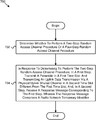
- One embodiment of a method includes determining whether to perform a two-step random access channel procedure or a four-step random access channel procedure.
- the method includes, in response to determining to perform the two-step random access channel procedure: in a first step: transmitting a preamble in a first time slot; and transmitting an uplink data transmission via a physical uplink shared channel in a second time slot different from the first time slot; and, in a second step, receiving a response message corresponding to the first step, wherein the response message comprises a radio network temporary identifier.
- One apparatus for performing a two-step random access channel procedure includes a processor that determines whether to perform a two-step random access channel procedure or a four-step random access channel procedure.
- the apparatus includes a transmitter.
- the apparatus includes a receiver.
- in response to determining to perform the two-step random access channel procedure in a first step, the transmitter: transmits a preamble in a first time slot; and transmits an uplink data transmission via a physical uplink shared channel in a second time slot different from the first time slot; and in a second step, the receiver receives a response message corresponding to the first step, wherein the response message comprises a radio network temporary identifier.
- Another embodiment of a method for performing a two-step random access channel procedure includes receiving a preamble in a first time slot and receiving an uplink data transmission via a physical uplink shared channel in a second time slot different from the first time slot in response to a determination by a remote unit to perform a two-step random access channel procedure.
- the method includes transmitting a response message corresponding to the preamble and the uplink data transmission, wherein the response message comprises a radio network temporary identifier.
- One apparatus for performing a two-step random access channel procedure includes a receiver that receives a preamble in a first time slot and receiving an uplink data transmission via a physical uplink shared channel in a second time slot different from the first time slot in response to a determination by a remote unit to perform a two-step random access channel procedure.
- the apparatus includes a transmitter that transmits a response message corresponding to the preamble and the uplink data transmission, wherein the response message comprises a radio network temporary identifier.
- FIG. 1 is a schematic block diagram illustrating one embodiment of a wireless communication system for performing a two-step random access channel procedure
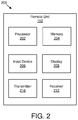
- FIG. 2 is a schematic block diagram illustrating one embodiment of an apparatus that may be used for performing a two-step random access channel procedure
- FIG. 3 is a schematic block diagram illustrating one embodiment of an apparatus that may be used for performing a two-step random access channel procedure
- FIG. 4 is a communication diagram illustrating one embodiment of communications as part of a RACH procedure
- FIG. 5 is a communication diagram illustrating another embodiment of communications as part of a RACH procedure
- FIG. 6 is a resource diagram illustrating a time offset and a frequency offset
- FIG. 7 is a flow chart diagram illustrating one embodiment of a method for performing a two-step random access channel procedure.
- FIG. 8 is a flow chart diagram illustrating another embodiment of a method for performing a two-step random access channel procedure.
- embodiments may be embodied as a system, apparatus, method, or program product. Accordingly, embodiments may take the form of an entirely hardware embodiment, an entirely software embodiment (including firmware, resident software, micro-code, etc.) or an embodiment combining software and hardware aspects that may all generally be referred to herein as a “circuit,” “module” or “system.” Furthermore, embodiments may take the form of a program product embodied in one or more computer readable storage devices storing machine readable code, computer readable code, and/or program code, referred hereafter as code. The storage devices may be tangible, non-transitory, and/or non-transmission. The storage devices may not embody signals. In a certain embodiment, the storage devices only employ signals for accessing code.
- modules may be implemented as a hardware circuit comprising custom very-large-scale integration (“VLSI”) circuits or gate arrays, off-the-shelf semiconductors such as logic chips, transistors, or other discrete components.
- VLSI very-large-scale integration
- a module may also be implemented in programmable hardware devices such as field programmable gate arrays, programmable array logic, programmable logic devices or the like.
- Modules may also be implemented in code and/or software for execution by various types of processors.
- An identified module of code may, for instance, include one or more physical or logical blocks of executable code which may, for instance, be organized as an object, procedure, or function. Nevertheless, the executables of an identified module need not be physically located together, but may include disparate instructions stored in different locations which, when joined logically together, include the module and achieve the stated purpose for the module.
- a module of code may be a single instruction, or many instructions, and may even be distributed over several different code segments, among different programs, and across several memory devices.
- operational data may be identified and illustrated herein within modules, and may be embodied in any suitable form and organized within any suitable type of data structure. The operational data may be collected as a single data set, or may be distributed over different locations including over different computer readable storage devices.
- the software portions are stored on one or more computer readable storage devices.
- the computer readable medium may be a computer readable storage medium.
- the computer readable storage medium may be a storage device storing the code.
- the storage device may be, for example, but not limited to, an electronic, magnetic, optical, electromagnetic, infrared, holographic, micromechanical, or semiconductor system, apparatus, or device, or any suitable combination of the foregoing.
- a storage device More specific examples (a non-exhaustive list) of the storage device would include the following: an electrical connection having one or more wires, a portable computer diskette, a hard disk, a random access memory (“RAM”), a read-only memory (“ROM”), an erasable programmable read-only memory (“EPROM” or Flash memory), a portable compact disc read-only memory (“CD-ROM”), an optical storage device, a magnetic storage device, or any suitable combination of the foregoing.
- a computer readable storage medium may be any tangible medium that can contain, or store a program for use by or in connection with an instruction execution system, apparatus, or device.
- Code for carrying out operations for embodiments may be any number of lines and may be written in any combination of one or more programming languages including an object oriented programming language such as Python, Ruby, Java, Smalltalk, C++, or the like, and conventional procedural programming languages, such as the “C” programming language, or the like, and/or machine languages such as assembly languages.
- the code may execute entirely on the user's computer, partly on the user's computer, as a stand-alone software package, partly on the user's computer and partly on a remote computer or entirely on the remote computer or server.
- the remote computer may be connected to the user's computer through any type of network, including a local area network (“LAN”) or a wide area network (“WAN”), or the connection may be made to an external computer (for example, through the Internet using an Internet Service Provider).
- LAN local area network
- WAN wide area network
- Internet Service Provider an Internet Service Provider
- the code may also be stored in a storage device that can direct a computer, other programmable data processing apparatus, or other devices to function in a particular manner, such that the instructions stored in the storage device produce an article of manufacture including instructions which implement the function/act specified in the schematic flowchart diagrams and/or schematic block diagrams block or blocks.
- the code may also be loaded onto a computer, other programmable data processing apparatus, or other devices to cause a series of operational steps to be performed on the computer, other programmable apparatus or other devices to produce a computer implemented process such that the code which execute on the computer or other programmable apparatus provide processes for implementing the functions/acts specified in the flowchart and/or block diagram block or blocks.
- each block in the schematic flowchart diagrams and/or schematic block diagrams may represent a module, segment, or portion of code, which includes one or more executable instructions of the code for implementing the specified logical function(s).
- FIG. 1 depicts an embodiment of a wireless communication system 100 for performing a two-step random access channel procedure.
- the wireless communication system 100 includes remote units 102 and network units 104 . Even though a specific number of remote units 102 and network units 104 are depicted in FIG. 1 , one of skill in the art will recognize that any number of remote units 102 and network units 104 may be included in the wireless communication system 100 .
- the remote units 102 may include computing devices, such as desktop computers, laptop computers, personal digital assistants (“PDAs”), tablet computers, smart phones, smart televisions (e.g., televisions connected to the Internet), set-top boxes, game consoles, security systems (including security cameras), vehicle on-board computers, network devices (e.g., routers, switches, modems), aerial vehicles, drones, or the like.
- the remote units 102 include wearable devices, such as smart watches, fitness bands, optical head-mounted displays, or the like.
- the remote units 102 may be referred to as subscriber units, mobiles, mobile stations, users, terminals, mobile terminals, fixed terminals, subscriber stations, UE, user terminals, a device, or by other terminology used in the art.
- the remote units 102 may communicate directly with one or more of the network units 104 via UL communication signals.
- the network units 104 may be distributed over a geographic region.
- a network unit 104 may also be referred to as an access point, an access terminal, a base, a base station, a Node-B, an eNB, a gNB, a Home Node-B, a relay node, a device, a core network, an aerial server, a radio access node, an AP, NR, a network entity, an AMF, a UDM, a UDR, a UDM/UDR, a PCF, a RAN, an NSSF, or by any other terminology used in the art.
- the network units 104 are generally part of a radio access network that includes one or more controllers communicably coupled to one or more corresponding network units 104 .
- the radio access network is generally communicably coupled to one or more core networks, which may be coupled to other networks, like the Internet and public switched telephone networks, among other networks. These and other elements of radio access and core networks are not illustrated but are well known generally by those having ordinary skill in the art.
- the wireless communication system 100 is compliant with NR protocols standardized in 3GPP, wherein the network unit 104 transmits using an OFDM modulation scheme on the DL and the remote units 102 transmit on the UL using a SC-FDMA scheme or an OFDM scheme. More generally, however, the wireless communication system 100 may implement some other open or proprietary communication protocol, for example, WiMAX, IEEE 802.11 variants, GSM, GPRS, UMTS, LTE variants, CDMA2000, Bluetooth®, ZigBee, Sigfoxx, among other protocols. The present disclosure is not intended to be limited to the implementation of any particular wireless communication system architecture or protocol.
- the network units 104 may serve a number of remote units 102 within a serving area, for example, a cell or a cell sector via a wireless communication link.
- the network units 104 transmit DL communication signals to serve the remote units 102 in the time, frequency, and/or spatial domain.
- a remote unit 102 may determine whether to perform a two-step random access channel procedure or a four-step random access channel procedure. In some embodiments, the remote unit 102 may, in response to determining to perform the two-step random access channel procedure: in a first step: transmit a preamble in a first time slot; and transmit an uplink data transmission via a physical uplink shared channel in a second time slot different from the first time slot; and, in a second step, receive a response message corresponding to the first step, wherein the response message comprises a radio network temporary identifier. Accordingly, the remote unit 102 may be used for performing a two-step random access channel procedure.
- a network unit 104 may receive a preamble in a first time slot and receiving an uplink data transmission via a physical uplink shared channel in a second time slot different from the first time slot in response to a determination by a remote unit to perform a two-step random access channel procedure.
- the network unit 104 may transmit a response message corresponding to the preamble and the uplink data transmission, wherein the response message comprises a radio network temporary identifier. Accordingly, the network unit 104 may be used for performing a two-step random access channel procedure.
- FIG. 2 depicts one embodiment of an apparatus 200 that may be used for performing a two-step random access channel procedure.
- the apparatus 200 includes one embodiment of the remote unit 102 .
- the remote unit 102 may include a processor 202 , a memory 204 , an input device 206 , a display 208 , a transmitter 210 , and a receiver 212 .
- the input device 206 and the display 208 are combined into a single device, such as a touchscreen.
- the remote unit 102 may not include any input device 206 and/or display 208 .
- the remote unit 102 may include one or more of the processor 202 , the memory 204 , the transmitter 210 , and the receiver 212 , and may not include the input device 206 and/or the display 208 .
- the processor 202 may include any known controller capable of executing computer-readable instructions and/or capable of performing logical operations.
- the processor 202 may be a microcontroller, a microprocessor, a central processing unit (“CPU”), a graphics processing unit (“GPU”), an auxiliary processing unit, a field programmable gate array (“FPGA”), or similar programmable controller.
- the processor 202 executes instructions stored in the memory 204 to perform the methods and routines described herein.
- the processor 202 may determine whether to perform a two-step random access channel procedure or a four-step random access channel procedure.
- the processor 202 is communicatively coupled to the memory 204 , the input device 206 , the display 208 , the transmitter 210 , and the receiver 212 .
- the memory 204 in one embodiment, is a computer readable storage medium.
- the memory 204 includes volatile computer storage media.
- the memory 204 may include a RAM, including dynamic RAM (“DRAM”), synchronous dynamic RAM (“SDRAM”), and/or static RAM (“SRAM”).
- the memory 204 includes non-volatile computer storage media.
- the memory 204 may include a hard disk drive, a flash memory, or any other suitable non-volatile computer storage device.
- the memory 204 includes both volatile and non-volatile computer storage media.
- the memory 204 also stores program code and related data, such as an operating system or other controller algorithms operating on the remote unit 102 .
- the input device 206 may include any known computer input device including a touch panel, a button, a keyboard, a stylus, a microphone, or the like.
- the input device 206 may be integrated with the display 208 , for example, as a touchscreen or similar touch-sensitive display.
- the input device 206 includes a touchscreen such that text may be input using a virtual keyboard displayed on the touchscreen and/or by handwriting on the touchscreen.
- the input device 206 includes two or more different devices, such as a keyboard and a touch panel.
- the display 208 may include any known electronically controllable display or display device.
- the display 208 may be designed to output visual, audible, and/or haptic signals.
- the display 208 includes an electronic display capable of outputting visual data to a user.
- the display 208 may include, but is not limited to, an LCD display, an LED display, an OLED display, a projector, or similar display device capable of outputting images, text, or the like to a user.
- the display 208 may include a wearable display such as a smart watch, smart glasses, a heads-up display, or the like.
- the display 208 may be a component of a smart phone, a personal digital assistant, a television, a table computer, a notebook (laptop) computer, a personal computer, a vehicle dashboard, or the like.
- the display 208 includes one or more speakers for producing sound.
- the display 208 may produce an audible alert or notification (e.g., a beep or chime).
- the display 208 includes one or more haptic devices for producing vibrations, motion, or other haptic feedback.
- all or portions of the display 208 may be integrated with the input device 206 .
- the input device 206 and display 208 may form a touchscreen or similar touch-sensitive display.
- the display 208 may be located near the input device 206 .
- the transmitter 210 in response to determining to perform the two-step random access channel procedure: in a first step, the transmitter 210 : transmits a preamble in a first time slot; and transmits an uplink data transmission via a physical uplink shared channel in a second time slot different from the first time slot; and in a second step, the receiver 212 receives a response message corresponding to the first step, wherein the response message comprises a radio network temporary identifier.
- the remote unit 102 may have any suitable number of transmitters 210 and receivers 212 .
- the transmitter 210 and the receiver 212 may be any suitable type of transmitters and receivers. In one embodiment, the transmitter 210 and the receiver 212 may be part of a transceiver.
- FIG. 3 depicts one embodiment of an apparatus 300 that may be used for performing a two-step random access channel procedure.
- the apparatus 300 includes one embodiment of the network unit 104 .
- the network unit 104 may include a processor 302 , a memory 304 , an input device 306 , a display 308 , a transmitter 310 , and a receiver 312 .
- the processor 302 , the memory 304 , the input device 306 , the display 308 , the transmitter 310 , and the receiver 312 may be substantially similar to the processor 202 , the memory 204 , the input device 206 , the display 208 , the transmitter 210 , and the receiver 212 of the remote unit 102 , respectively.
- the receiver 312 receives a preamble in a first time slot and receives an uplink data transmission via a physical uplink shared channel in a second time slot different from the first time slot in response to a determination by a remote unit to perform a two-step random access channel procedure.
- the transmitter 310 transmits a response message corresponding to the preamble and uplink data transmission, wherein the response message comprises a radio network temporary identifier.
- the network unit 104 may have any suitable number of transmitters 310 and receivers 312 .
- the transmitter 310 and the receiver 312 may be any suitable type of transmitters and receivers.
- the transmitter 310 and the receiver 312 may be part of a transceiver.
- a CBRA procedure involves the exchange of four messages.
- each of the four messages exchanged during the RACH procedure may undergo a CCA procedure before a transmission may be made on the unlicensed cell.
- a 2-step RACH procedure may be used.
- Certain details of a 2-step RACH procedure may include: 1) a format and/or content of a response message (e.g., in step 2 of the 2-step RACH procedure); 2) power control issues for a preamble and an uplink transmission in step 1 of the 2-step RACH procedure; 3) uplink timing for a PUSCH transmission and a preamble transmission in step 1 of the 2-step RACH procedure; 4) switching between a 2-step RACH procedure and a 4-step RACH procedure; and/or 5 ) resource allocation for an uplink transmission in step 1 of the 2-step RACH procedure.
- FIG. 4 is a communication diagram illustrating one embodiment of communications 400 as part of a RACH procedure (e.g., 4-step RACH procedure).
- the communications 400 occur between a UE 402 (e.g., remote unit 102 ) and a gNB 404 (e.g., network unit 104 , gNB).
- a UE 402 e.g., remote unit 102
- a gNB 404 e.g., network unit 104 , gNB.
- each of the communications 400 described herein may include one or more messages.
- the gNB 404 transmits a SIB to the UE 402 in a first communication 406 transmitted from the gNB 404 to the UE 402 . In certain embodiments, in a second communication 408 transmitted from the UE 402 to the gNB 404 , the UE 402 transmits a PRACH preamble to the gNB 404 . In some embodiments, in a third communication 410 transmitted from the gNB 404 to the UE 402 , the gNB 404 transmits a RAR to the UE 402 in a third communication 410 transmitted from the gNB 404 to the UE 402 .
- the UE 402 transmits an uplink transmission on the PUSCH, e.g. connection request message to the gNB 404 .
- the gNB 404 transmits a contention resolution message to the UE 402 in a fourth communication 412 transmitted from the UE 402 to the gNB 404 .
- FIG. 4 shows CBRA. It should be noted that CFRA does not include the fourth communication 412 and the fifth communication 414 .
- CFRA does not include the fourth communication 412 and the fifth communication 414 .
- a UE may be allocated a RACH preamble and/or RACH resource (e.g., by means of a PDCCH order) that makes a need for a contention resolution obsolete.
- An RAR message may have the same content for CBRA and CFRA.
- a CFRA may be used for HO, uplink timing alignment, and beam failure recovery, for example.
- embodiments described herein may be applied to CBRA. Moreover, embodiments described herein may be described in the context of an unlicensed transmission and/or cell (e.g., NR-U); however, the embodiments herein may also be applicable to licensed cells (e.g., NR or LTE).
- NR-U unlicensed transmission and/or cell
- LTE licensed cells
- FIG. 5 is a communication diagram illustrating another embodiment of communications 500 as part of a RACH procedure (e.g., 2-step RACH procedure).
- the communications 500 occur between a UE 502 (e.g., remote unit 102 ) and an gNB 504 (e.g., network unit 104 , gNB).
- a UE 502 e.g., remote unit 102
- an gNB 504 e.g., network unit 104 , gNB
- each of the communications 500 described herein may include one or more messages.
- the gNB 504 transmits a SIB to the UE 502 .
- a second communication 508 e.g., first step in the 2-step RACH procedure, msg1 and msg3 of the 4-step RACH procedure
- the UE 502 transmits a PRACH preamble to the gNB 504 and an uplink transmission (e.g., on PUSCH).
- the gNB 504 transmits a RAR and a contention resolution message to the UE 502 (e.g., second step in the 2-step RACH procedure, msg2 and msg4 of the 4-step RACH procedure).
- a UE after having sent in a first step of a 2-step RACH procedure a preamble-like signal and an initial uplink transmission (e.g., on PUSCH), monitors for one or more response messages (e.g., in a second step of the 2-step RACH procedure) sent from a gNB.
- the UE may monitor for the one or more response messages during a defined time period (e.g., time window).
- the UE monitors during the time window for a PDCCH identified by an RA-RNTI scheduling PDSCH resources on which the one or more response messages are transmitted.
- an initial uplink transmission transmitted in a first step of the 2-step RACH procedure may include a TB containing at least a UE identifier such as a C-RNTI MAC control element or a UL CCCH SDU.
- the TB may contain data of a data radio bearer or control information such as a BSR or a PHR.
- a response message (e.g., in step 2 of a 2-step RACH procedure) sent from a network device (e.g., gNB) in response to the successful detection of a preamble-like signal (e.g., sent in step 1 of the 2-step RACH procedure together with an initial uplink transmission) contains a random access preamble identifier field identifying a preamble received.
- the response message may contain a TA Value that the gNB uses to inform the UE to change its timing so it may compensate for a round trip delay caused by the UE distance from the gNB.
- the response message may include an UL grant field within which a gNB may schedule a retransmission of a transport block transmitted in step-1 of a 2-step RACH procedure or a new initial uplink transmission.
- the gNB may schedule a retransmission of the TB.
- the gNB may decode the TB as soon as possible to resolve a potential contention.
- a HARQ process used for the transmission of an uplink transmission (e.g., on PUSCH) in step 1 of a 2-step RACH procedure may be predefined, preconfigured, and/or fixed in a standard.
- an UL grant contained within a response message may allocate multiple uplink resources for an initial transmission or retransmission (e.g., for transmissions on an unlicensed cell).
- a response message may contain an ID field echoing the identifier sent in step 1, thereby resolving a potential contention. For example, if an uplink transmission in step 1 containing a C-RNTI MAC CE (e.g., for UEs in an RRC CONNECTED state having already a C-RNTI allocated) is successfully decoded, the response message may contain a C-RNTI MAC CE set to the same value as the C-RNTI MAC CE sent in step 1.
- the response message may carry a UE contention resolution ID MAC CE (e.g., first 48 bits of the UL CCCH SDU transmitted in step 1).
- a response message may not contain an identifier field (e.g., C-RNTI MAC CE or UE contention resolution ID MAC CE) because the identity of a UE is not known to a gNB.
- a potential contention may not be resolved (e.g., one or more further retransmissions of the uplink transmission of step 1 is required).
- a response message may contain a temporary C-RNTI field that may include an identity assigned by a gNB for further communication.
- the temporary C-RNTI field may only be present in the response message, such as if a TB sent in step 1 of a 2-step RACH procedure is not able to be successfully decoded or if the TB sent in step 1 contains a UL CCCH SDU (e.g., if a UE is in an RRC_IDLE state).
- a C-RNTI field may not be used if the UE already has an assigned C-RNTI that is known to the gNB.
- a temporary C-RNTI field is always present in a response message and a UE may ignore the temporary C-RNTI field upon reception of the response message if the identifier sent in the response message (e.g., temporary C-RNTI MAC CE) matches an ID sent in step 1 of the 2-step RACH procedure.
- a response message of a 2-step RACH procedure is transmitted within a RACH response message transmitted on a PDSCH (e.g., MAC PDU).
- a UE may monitor upon transmission of a preamble and an UL transmission during a RACH response window for a response message (e.g., PDCCH addressed to RA-RNTI calculated from a timeslot in which the preamble is sent).
- a RAPID in a MAC subheader for a random access response indicates whether a corresponding MAC RAR is a legacy RAR or a new response message for a 2-step RACH.
- certain fields in a MAC RAR identify a response for a 2-step RACH and a legacy random access response.
- a reserved bit in a MAC RAR e.g., see Table 1 may be used to indicate a format of the MAC RAR (e.g., response for 2-step RACH or a legacy RAR—4-step RACH RAR).
- a first reserved bit set to ‘1’ indicates that a response for a 2-step RACH procedure is contained within the MAC RAR.
- a format for a MAC RAR that includes a response for a 2-step RACH procedure may be different than a legacy MAC RAR format.
- a response message for a 2-step RACH may schedule a retransmission of an uplink transmission made in step 1 of the 2-step RACH procedure.
- an indicator that distinguishes between an UL grant for a retransmission and an initial transmission may be contained in the UL grant field.
- a response message for a 2-step RACH procedure may contain a C-RNTI MAC CE or a UE contention resolution ID MAC CE (e.g., depending on a decoding status of a first uplink transmission and a UE RRC state).
- a MAC RAR containing a response for 2-step RACH procedure may have a variable size.
- extension bits may indicate a presence of a C-RNTI MAC CE or a UE contention resolution ID MAC CE.
- a response message for a 2-step RACH procedure may contain a DL allocation (e.g., either a DL TB or DL grant information pointing to PDSCH resources).
- a RNTI used for identifying a response for a 2-step RACH procedure may be calculated differently (e.g., using a different formula) than the RA-RNTI used for a RAR of a legacy RACH procedure (e.g., 4-step RACH procedure).
- a legacy RACH procedure may refer to a 4-step RACH procedure.
- a UE in response to not receiving a response message in step 2 of a 2-step RACH procedure, may repeat step 1 of the 2-step RACH procedure and may send a preamble-like signal together with an uplink transmission.
- a UE that does not successfully receive a response message within a defined time window may assume that a preamble was not detected by a gNB.
- a UE transmits or retransmits a preamble and an uplink transmission sent previously in step 1 of a 2-step RACH procedure with an increased transmission power than a transmission power used for a previous transmission of the preamble and the uplink transmission (e.g., power ramping may be applied to both the preamble and the uplink transmission).
- a UE switches to a legacy 4-step RACH procedure in the absence of a response message during a defined time window.
- a UE if a UE doesn't successfully receive a response message for a 2-step RACH procedure, the UE switches to the legacy 4-step RACH procedure and subsequently transmits only a preamble (e.g., no UL transmission on PUSCH with the preamble).
- a preamble transmission may be transmitted with an increased transmission power as compared to a previous preamble transmission (e.g., power ramping).
- a UE may select a preamble reserved for the 4-step RACH procedure.
- a UE stores a MAC PDU sent in step 1 of a 2-step RACH procedure in a Msg3 buffer if switching to a 4-step RACH procedure.
- a new transmission buffer may be used in which a UE stores a MAC PDU sent in step 1 of a 2-step RACH procedure after generating the MAC PDU.
- storing a MAC PDU generated for step 1 in a separate buffer may enable later retransmissions of the generated MAC PDU (e.g., if contention resolution fails).
- a UE transmits or retransmits a preamble together with an uplink (e.g., UL-SCH) transmission in the absence of a response message.
- the UE may determine whether to apply power ramping (e.g., transmitting with an increased TX power compared to a previous transmission) for both the preamble and the uplink transmission or for only the preamble.
- a UE calculates a required transmission power for both a preamble transmission P preamble using a power control formula specified for preamble transmission thereby assuming an predefined power offset and for an uplink transmission P UL using a power control formula specified for the uplink transmission to account for the predefined power offset.
- the predefined power offset also referred to as Power_Ramping_Stepsize
- the predefined power offset may be separately defined for the preamble transmission and the uplink transmission.
- a sum of a required transmission power for a preamble and an uplink transmission e.g., including power offsets
- a UE's total maximum transmission power e.g., P CMAX,f,c (i)
- power ramping may be applied to both the preamble and the uplink transmission.
- P CMAX,f,c (i) total maximum transmission power ramping may be applied to both the preamble and the uplink transmission.
- P cmax,c power ramping may only be applied to the preamble transmission.
- P Preamble including a power offset and P UL without consideration of a power offset exceeds P CMAX,f,c (i)
- a UE may switch to a legacy 4-step RACH procedure.
- a UE transmits a preamble-like signal and an uplink data transmission conveyed by PUSCH (e.g., elements forming step 1 in a 2-step RACH procedure) in different time slots.
- PUSCH e.g., elements forming step 1 in a 2-step RACH procedure
- one benefit of transmitting the preamble-like signal and the uplink data transmission in different time slots may be that a power between the preamble-like signal and the uplink data transmission does not need to be shared so that both transmissions may operate at optimum coverage (e.g., optimal power).
- a network node e.g., gNB
- transmitting the preamble-like signal and the uplink data transmission in different time slots may eliminate and/or reduce the need for precautionary buffering of a received time slot.
- a gNB may configure a time offset that a UE has to observe between a transmission of a preamble-like signal and a transmission of uplink data.
- the configuration may be advertised (e.g., in broadcast information in an SIB because all UEs may observe the same offset).
- an offset may depend on an employed subcarrier spacing (e.g., because a duration of a preamble-like signal may be a function of the subcarrier spacing) even though a required detection time may not scale equally.
- an offset may be 1 slot, and in another subcarrier spacing the offset may be 2 slots.
- an offset can be 0 slots (e.g., implying that a preamble-like signal and an uplink data transmission occur in the same slot).
- this may be beneficial in an unlicensed carrier configuration in which the UE contends for channel access (e.g., where any gap may bear the risk of losing a right to transmit on a channel), or with interference from a hidden node.
- a UE may perform a clear channel assessment before transmission of uplink data. As may be appreciated, this may result in not being able to transmit the uplink data in a designated slot due to a blocked channel.
- a UE repeats a transmission of a preamble-like signal and uplink data for a number of consecutive slots based on an offset value.
- an offset value is n_o
- a UE may transmit and/or repeat a preamble-like signal during n_o slots followed by uplink data transmitted and/or repeated during n_o slots.
- the gNB may be able to receive an uplink data signal in slot n1+n_o.
- an offset may be set to a fixed value of 1 slot so that a preamble-like transmission and uplink data transmission occur in adjacent slots. As may be appreciated, this does not require a configuration of an offset value and, therefore, uses less overhead than configurations in which the offset is configured via a message and/or signaling.
- a transmission of a preamble-like signal and uplink data occur in the same slot, available transmit power of a UE may be shared.
- the preamble-like signal may be prioritized over the uplink data signal so that the preamble-like signal is transmitted with a designated power, and the transmit power of the uplink data signal is reduced to not exceed a total available transmit power.
- a good reception quality of the preamble-like signal may be made. Having good reception quality for the preamble-like signa may be more important than good reception quality of the uplink data transmission for the RACH procedure.
- the gNB may still be aware that a RACH procedure has been initiated by the UE, and may request a retransmission of the uplink data.
- a UE may use the same power control parameters for calculating a transmit power P PUSCH,b,f,c (i,j,q d ,l) of the uplink transmission in step 1 of the 2-step RACH procedure as the power control parameters used for a msg3 PUSCH transmission.
- the power control parameters may include P O_PUSCH,b,f,c , ⁇ b,f,c, , PL b,f,c (q d ).
- the PUSCH transmission in step 1 of the 2-step RACH procedure may be treated as a msg3 PUSCH transmission from a power control perspective.
- separate power control parameters may be defined for a PUSCH transmission in step 1 of a 2-step RACH procedure (e.g., separate values are defined for P O_PUSCH,b,f,c , ⁇ b,f,c, , PL b,f,c (q d ) to satisfy different requirements in terms of reliability (e.g., BLER) or latency).
- reliability e.g., BLER
- latency e.g., the following formula may be used:
- P PUSCH , b , f , c ⁇ ( i , j , q d , l ) min ⁇ ⁇ P CMAX , f , c ⁇ ( i ) , P O ⁇ _ ⁇ PUSCH , b , f , c ⁇ ( j ) + 10 ⁇ log 10 ⁇ ( 2 ⁇ ⁇ M RB , b , f , c PUSCH ⁇ ( i ) ) + ⁇ b , f , c ⁇ ( j ) ⁇ PL b , f , c ⁇ ( q d ) + ⁇ TF , b , f , c ⁇ ( i ) + f b , f , c ⁇ ( i , l ) ⁇
- M RB,b,f,c PUSCH (i) is the bandwidth of the PUSCH resource assignment expressed in number of resource blocks for PUSCH transmission occasion i on UL BWP b of carrier f of serving cell c and ⁇ may be predefined.
- PL b,f,c (q d ) is a downlink path-loss estimate in dB calculated by the UE using reference signal (RS) index q d for a DL BWP that is linked with UL BWP b of carrier f of serving cell c.
- RS reference signal
- the UE calculates PL b,f,c (q d ) using a RS resource from the SS/PBCH block index that the UE obtains higher layer parameter MasterInformationBlock.
- the UE is configured with a number of RS resource indexes up to the value of higher layer parameter maxNrofPUSCH-PathlossReferenceRSs and a respective set of RS configurations for the number of RS resource indexes by higher layer parameter PUSCH-PathlossReferenceRS.
- the set of RS resource indexes can include one or both of a set of SS/PBCH block indexes, each provided by higher layer parameter ssb-Index when a value of a corresponding higher layer parameter pusch-PathlossReferenceRS-Id maps to a SS/PBCH block index, and a set of CSI-RS resource indexes, each provided by higher layer parameter csi-RS-Index when a value of a corresponding higher layer parameter pusch-PathlossReferenceRS-Id maps to a CSI-RS resource index.
- the UE identifies a RS resource index in the set of RS resource indexes to correspond either to a SS/PBCH block index or to a CSI-RS resource index as provided by higher layer parameter pusch-PathlossReferenceRS-Id in PUSCH-PathlossReferenceRS.
- the UE uses the same RS resource index as for a corresponding PRACH transmission.
- referenceSignalPower is provided by higher layer parameter ss-PBCH-BlockPower.
- referenceSignalPower is configured by either higher layer parameter ss-PBCH-BlockPower or, when periodic CSI-RS transmission is configured, by higher layer parameter powerControlOffsetSS providing an offset of the CSI-RS transmission power relative to the SS/PBCH block transmission power.
- BPRE and ⁇ offset PUSCH for each UL BWP b of each carrier f and each serving cell c, are computed as below.
- C is the number of code blocks
- K r is the size for code block r
- O CSI is the number of CSI part 1 bits including CRC bits
- N RE is the number of resource elements determined as
- N symb,b,f,c PUSCH (i) is the number of symbols for PUSCH transmission occasion i on UL BWP b of carrier f of serving cell c
- N sc,data RB (i,j) is a number of subcarriers excluding DM-RS subcarriers in PUSCH symbol j, 0 ⁇ j ⁇ N symb,b,f,c PUSCH (i)
- Cm K r are defined in [5, TS 38.212].
- a UE may defer the uplink data transmission to a later slot if insufficient power is available for transmission of the preamble-like signal and the uplink data in the same slot.
- a UE may defer an uplink data transmission to a next slot after a slot used to transmit a preamble-like signal so that the preamble-like signal and uplink data are transmitted in adjacent slots.
- a gNB performs a blind detection of uplink data at expected resources in the same slot and one or more slots after a detected preamble-like signal.
- a preamble-like signal indicates whether uplink data is transmitted in the same slot, or deferred to a later slot.
- a plurality of preamble-like signals forms two or more sets in which the transmission of a preamble-like signal from a first set indicates that the uplink data is transmitted in the same slot as the preamble-like signal.
- the preamble-like signal is from a second set, this indicates that transmission of the uplink data is deferred to a later slot than the preamble-like signal (e.g., to the next slot).
- partitioning of the preamble-like signals to sets may be defined in a communication system, or configured by a network (e.g., by broadcast in system information or by dedicated configuration signals).
- a UE before it performs transmission of step 1 of a 2-step RACH procedure, may determine which resources may be used for transmitting a preamble and an uplink transmission.
- PRACH resources are determined as in a 4-step RACH procedure (e.g., using RACH-ConfigGeneric parameters broadcasted as part of SIB1 in 5G NR). It should be noted that parameters used to determine PUSCH resources may be broadcast specifically for the purpose of transmitting step 1 of a 2-step RACH procedure. Accordingly, the PUSCH resources to be used by the UE may have a linking to chosen PRACH resources.
- the linking may be accomplished using one or more of the following offsets: 1) frequency offset, O_f: offset of lowest PUSCH transmission occasion in a frequency domain with respective to PRACH resources defined by msg1-FrequencyStart in 5G NR system; and/or 2 ) time offset, T_f: offset of lowest PUSCH transmission occasion in time domain with respective to PRACH transmission occasion chosen by the UE.
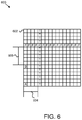
- FIG. 6 is a resource diagram 600 illustrating a time offset and a frequency offset.
- the resource diagram 600 includes a 16 ⁇ 16 grid of resource elements 602 .
- One resource element 602 is PRB0 “A”
- another resource element 602 is the PRACH resource “B”.
- a time offset 604 “T_f” is defined relative to the PRACH resource B to indicate a lowest time “T” in the time domain for a PUSCH transmission. This is illustrated by the column of resource elements 602 T.
- a frequency offset 608 “O_f” is defined relative to the PRACH resource B to indicate a lowest frequency “F” in the frequency domain for a PUSCH transmission. This is illustrated by the row of resource elements 602 F.
- the intersection of the lowest time T and the lowest frequency F is illustrated by resource element 602 “C”.
- a time offset may be a value in a number of symbols, a number of slots, or in milliseconds.
- more than one set of O_f and T_f may be broadcast such that for one preamble ID or group of preambles IDs, one specific set of O_f and T_f may be used. For example, if 2 sets of O_f and T_f are broadcast then a first half of the preambles used in this cell (e.g., 0 . . . 31) may use the first set of O_f and T_f and the second half of the preambles used in this cell (e.g., 32 . . . 63) may use the second set of O_f and T_f.
- a dedicated RRC signaling or specified values may also be used (e.g., for a non-initial random access procedure).
- a network may configure how many PRBs are used for transmitting PUSCH of step 1 of a 2-step RACH procedure using RRC signaling.
- physical layer parameters like MCS may be specified or configured using RRC signaling for transmitting the PUSCH of step 1 of a 2-step RACH procedure.
- a UE decides whether to start a 2-step RACH procedure or a legacy 4-step RACH procedure once an RACH procedure has been triggered depending on certain criteria.
- a UE may determine whether to start a 2-step RACH procedure or a 4-step RACH procedure based on e.g., its power status.
- the UE calculates a required transmission power for both a preamble transmission P preamble according to the power control formula specified for preamble transmission and for an uplink transmission P UL according to a power control formula specified for the uplink transmission.
- a UE if the sum of P preamble and P UL doesn't exceed a UE's total maximum transmission power (e.g., P cmax,c ), a UE starts a 2-step RACH procedure, otherwise the UE uses the 4-step RACH procedure.
- a criterion for determining whether to use a 2-step RACH procedure or a 4-step RACH procedure may be a size of data to be transmitted in an UL transmission (e.g., if the size of the data is above a certain configured threshold, the UE may use the 4-step RACH procedure).
- a network entity configures whether a UE is enabled, allowed, and/or obliged to perform a 2-step RACH procedure and/or a 4-step RACH procedure in a current cell.
- the configuration may be made per RACH type (e.g., the 2-step RACH procedure is used for handover situations and for scheduling request purposes the 4-step RACH procedure is used).
- a PDCCH order or a RRC message ordering a handover may indicate whether to use a legacy contention-free RACH procedure or a 2-step RACH procedure (e.g., a handover complete message may be included in step 1 of the 2-step RACH procedure).
- a configuration and/or a specification may indicate that a 2-step RACH procedure is used in an unlicensed spectrum.
- use of a 2-step RACH procedure or a 4-step RACH procedure may be tied to COT (e.g., determining to use either the 2-step RACH procedure or the 4-step RACH procedure based on whether the COT is above and/or below certain threshold).
- a UE is enabled to use a channel access Type 2 (e.g., implying a fixed or shorter sensing interval for a CCA procedure) for transmission of a preamble-like signal and an uplink transmission in step 1 of a 2-step RACH procedure.
- a channel access Type 2 e.g., implying a fixed or shorter sensing interval for a CCA procedure
- FIG. 7 is a flow chart diagram illustrating one embodiment of a method 700 for performing a two-step random access channel procedure.
- the method 700 is performed by an apparatus, such as the remote unit 102 .
- the method 700 may be performed by a processor executing program code, for example, a microcontroller, a microprocessor, a CPU, a GPU, an auxiliary processing unit, a FPGA, or the like.
- the method 700 may include determining 702 whether to perform a two-step random access channel procedure or a four-step random access channel procedure.
- the method 700 includes, in response to determining to perform the two-step random access channel procedure: in a first step: transmitting 704 a preamble in a first time slot; and transmitting an uplink data transmission via a physical uplink shared channel in a second time slot different from the first time slot; and, in a second step, receiving a response message corresponding to the first step, wherein the response message comprises a radio network temporary identifier.
- the method 700 further comprises monitoring during a response window for the response message.
- the radio network temporary identifier for the two-step random access channel procedure is calculated using a first formula
- a radio network temporary identifier for the four-step random access channel procedure is calculated using a second formula different from the first formula.
- the uplink data transmission comprises a medium access control physical data unit.
- the method 700 further comprises storing the medium access control physical data unit in a buffer.
- the medium access control physical data unit is stored in the buffer in response to switching from the two-step random access channel procedure to the four-step random access channel procedure.
- the method 700 further comprises delaying for an offset time between transmission of the preamble and transmission of the uplink data transmission.
- the offset time corresponds to a subcarrier spacing.
- determining whether to perform the two-step random access channel procedure or the four-step random access channel procedure comprises determining whether to perform the two-step random access channel procedure or the four-step random access channel procedure based on a predetermined factor.
- the predetermined factor comprises a power status.
- the method 700 further comprises receiving information configuring a requirement for performing the two-step random access channel procedure.
- the information indicates that the two-step random access channel procedure is allowed. In one embodiment, the information indicates that the two-step random access channel procedure is required.
- FIG. 8 is a flow chart diagram illustrating another embodiment of a method 800 for performing a two-step random access channel procedure.
- the method 800 is performed by an apparatus, such as the network unit 104 .
- the method 800 may be performed by a processor executing program code, for example, a microcontroller, a microprocessor, a CPU, a GPU, an auxiliary processing unit, a FPGA, or the like.
- the method 800 may include receiving 802 a preamble in a first time slot and receiving an uplink data transmission via a physical uplink shared channel in a second time slot different from the first time slot in response to a determination by a remote unit to perform a two-step random access channel procedure.
- the method 800 includes transmitting 804 a response message corresponding to the preamble, wherein the response message comprises a radio network temporary identifier.
- the radio network temporary identifier for the two-step random access channel procedure is calculated using a first formula
- a radio network temporary identifier for a four-step random access channel procedure is calculated using a second formula different from the first formula.
- the uplink data transmission comprises a medium access control physical data unit.
- an offset time delay is between receiving the preamble and receiving the uplink data transmission.
- the offset time corresponds to a subcarrier spacing.
- the method 800 further comprises transmitting information configuring a requirement for performing the two-step random access channel procedure.
- the information indicates that the two-step random access channel procedure is allowed.
- the information indicates that the two-step random access channel procedure is required.
- a method comprises: determining whether to perform a two-step random access channel procedure or a four-step random access channel procedure; and, in response to determining to perform the two-step random access channel procedure: in a first step: transmitting a preamble in a first time slot; and transmitting an uplink data transmission via a physical uplink shared channel in a second time slot different from the first time slot; and, in a second step, receiving a response message corresponding to the first step, wherein the response message comprises a radio network temporary identifier.
- the method further comprises monitoring during a response window for the response message.
- the radio network temporary identifier for the two-step random access channel procedure is calculated using a first formula
- a radio network temporary identifier for the four-step random access channel procedure is calculated using a second formula different from the first formula.
- the uplink data transmission comprises a medium access control physical data unit.
- the method further comprises storing the medium access control physical data unit in a buffer.
- the medium access control physical data unit is stored in the buffer in response to switching from the two-step random access channel procedure to the four-step random access channel procedure.
- the method further comprises delaying for an offset time between transmission of the preamble and transmission of the uplink data transmission.
- the offset time corresponds to a subcarrier spacing.
- determining whether to perform the two-step random access channel procedure or the four-step random access channel procedure comprises determining whether to perform the two-step random access channel procedure or the four-step random access channel procedure based on a predetermined factor.
- the predetermined factor comprises a power status
- the method further comprises receiving information configuring a requirement for performing the two-step random access channel procedure.
- the information indicates that the two-step random access channel procedure is allowed.
- the information indicates that the two-step random access channel procedure is required.
- an apparatus comprises: a processor that determines whether to perform a two-step random access channel procedure or a four-step random access channel procedure; a transmitter; and a receiver, wherein in response to determining to perform the two-step random access channel procedure: in a first step, the transmitter: transmits a preamble in a first time slot; and transmits an uplink data transmission via a physical uplink shared channel in a second time slot different from the first time slot; and in a second step, the receiver receives a response message corresponding to the first step, wherein the response message comprises a radio network temporary identifier.
- the processor monitors during a response window for the response message.
- the radio network temporary identifier for the two-step random access channel procedure is calculated using a first formula
- a radio network temporary identifier for the four-step random access channel procedure is calculated using a second formula different from the first formula.
- the uplink data transmission comprises a medium access control physical data unit.
- the apparatus further comprising a buffer that stores the medium access control physical data unit.
- the medium access control physical data unit is stored in the buffer in response to switching from the two-step random access channel procedure to the four-step random access channel procedure.
- the processor delays for an offset time between transmission of the preamble and transmission of the uplink data transmission.
- the offset time corresponds to a subcarrier spacing.
- the processor determines whether to perform the two-step random access channel procedure or the four-step random access channel procedure by determining whether to perform the two-step random access channel procedure or the four-step random access channel procedure based on a predetermined factor.
- the predetermined factor comprises a power status
- the receiver receives information configuring a requirement for performing the two-step random access channel procedure.
- the information indicates that the two-step random access channel procedure is allowed.
- the information indicates that the two-step random access channel procedure is required.
- a method comprises: receiving a preamble in a first time slot and receiving an uplink data transmission via a physical uplink shared channel in a second time slot different from the first time slot in response to a determination by a remote unit to perform a two-step random access channel procedure; and transmitting a response message corresponding to the preamble, wherein the response message comprises a radio network temporary identifier.
- the radio network temporary identifier for the two-step random access channel procedure is calculated using a first formula
- a radio network temporary identifier for a four-step random access channel procedure is calculated using a second formula different from the first formula
- the uplink data transmission comprises a medium access control physical data unit.
- an offset time delay is between receiving the preamble and receiving the uplink data transmission.
- the offset time corresponds to a subcarrier spacing.
- the method further comprises transmitting information configuring a requirement for performing the two-step random access channel procedure.
- the information indicates that the two-step random access channel procedure is allowed.
- the information indicates that the two-step random access channel procedure is required.
- an apparatus comprises: a receiver that receives a preamble in a first time slot and receiving an uplink data transmission via a physical uplink shared channel in a second time slot different from the first time slot in response to a determination by a remote unit to perform a two-step random access channel procedure; and a transmitter that transmits a response message corresponding to the preamble, wherein the response message comprises a radio network temporary identifier.
- the radio network temporary identifier for the two-step random access channel procedure is calculated using a first formula
- a radio network temporary identifier for a four-step random access channel procedure is calculated using a second formula different from the first formula
- the uplink data transmission comprises a medium access control physical data unit.
- an offset time delay is between receiving the preamble and receiving the uplink data transmission.
- the offset time corresponds to a subcarrier spacing.
- the transmitter transmits information configuring a requirement for performing the two-step random access channel procedure.
- the information indicates that the two-step random access channel procedure is allowed.
- the information indicates that the two-step random access channel procedure is required.
Landscapes
- Engineering & Computer Science (AREA)
- Signal Processing (AREA)
- Computer Networks & Wireless Communication (AREA)
- Mobile Radio Communication Systems (AREA)
Priority Applications (3)
| Application Number | Priority Date | Filing Date | Title |
|---|---|---|---|
| US16/584,249 US11166319B2 (en) | 2018-09-26 | 2019-09-26 | Performing a two-step random access channel procedure |
| US17/515,770 US11653391B2 (en) | 2018-09-26 | 2021-11-01 | Performing a two-step random access channel procedure |
| US18/296,212 US12336014B2 (en) | 2018-09-26 | 2023-04-05 | Performing a two-step random access channel procedure |
Applications Claiming Priority (2)
| Application Number | Priority Date | Filing Date | Title |
|---|---|---|---|
| US201862736928P | 2018-09-26 | 2018-09-26 | |
| US16/584,249 US11166319B2 (en) | 2018-09-26 | 2019-09-26 | Performing a two-step random access channel procedure |
Related Child Applications (1)
| Application Number | Title | Priority Date | Filing Date |
|---|---|---|---|
| US17/515,770 Continuation US11653391B2 (en) | 2018-09-26 | 2021-11-01 | Performing a two-step random access channel procedure |
Publications (2)
| Publication Number | Publication Date |
|---|---|
| US20200100299A1 US20200100299A1 (en) | 2020-03-26 |
| US11166319B2 true US11166319B2 (en) | 2021-11-02 |
Family
ID=68655566
Family Applications (3)
| Application Number | Title | Priority Date | Filing Date |
|---|---|---|---|
| US16/584,249 Active US11166319B2 (en) | 2018-09-26 | 2019-09-26 | Performing a two-step random access channel procedure |
| US17/515,770 Active US11653391B2 (en) | 2018-09-26 | 2021-11-01 | Performing a two-step random access channel procedure |
| US18/296,212 Active US12336014B2 (en) | 2018-09-26 | 2023-04-05 | Performing a two-step random access channel procedure |
Family Applications After (2)
| Application Number | Title | Priority Date | Filing Date |
|---|---|---|---|
| US17/515,770 Active US11653391B2 (en) | 2018-09-26 | 2021-11-01 | Performing a two-step random access channel procedure |
| US18/296,212 Active US12336014B2 (en) | 2018-09-26 | 2023-04-05 | Performing a two-step random access channel procedure |
Country Status (5)
| Country | Link |
|---|---|
| US (3) | US11166319B2 (de) |
| EP (1) | EP3858079B1 (de) |
| CN (2) | CN118488603A (de) |
| ES (1) | ES3035100T3 (de) |
| WO (1) | WO2020065398A1 (de) |
Cited By (2)
| Publication number | Priority date | Publication date | Assignee | Title |
|---|---|---|---|---|
| US20210307073A1 (en) * | 2020-03-31 | 2021-09-30 | Asustek Computer Inc. | Method and apparatus for random access preamble partition for small data transmission in a wireless communication system |
| US20220287107A1 (en) * | 2019-07-05 | 2022-09-08 | Samsung Electronics Co., Ltd. | Apparatus and method for random access procedure in wireless communication system |
Families Citing this family (57)
| Publication number | Priority date | Publication date | Assignee | Title |
|---|---|---|---|---|
| JP2020109886A (ja) * | 2017-04-28 | 2020-07-16 | シャープ株式会社 | 端末装置および方法 |
| US11259292B2 (en) * | 2018-02-12 | 2022-02-22 | Qualcomm Incorporated | Response-based resource management |
| EP3817495A4 (de) * | 2018-06-28 | 2022-03-09 | Ntt Docomo, Inc. | Benutzerendgerät |
| US20210250985A1 (en) * | 2018-06-28 | 2021-08-12 | Ntt Docomo, Inc. | User terminal |
| CN113170503B (zh) * | 2018-09-28 | 2024-08-30 | 三星电子株式会社 | 无线通信系统中的随机接入方法和装置 |
| US11632801B2 (en) * | 2018-10-03 | 2023-04-18 | Qualcomm Incorporated | Message 1 of a two-step random access procedure |
| KR102174653B1 (ko) * | 2018-10-24 | 2020-11-05 | 연세대학교 산학협력단 | 무선 통신 시스템의 랜덤 액세스 장치 및 방법 |
| ES2995224T3 (en) * | 2019-01-07 | 2025-02-07 | Ericsson Telefon Ab L M | Method, terminal device, base station for power control in random access procedure |
| US12464470B2 (en) * | 2019-01-17 | 2025-11-04 | Apple Inc. | System and method for power control for 2-step random access channel (RACH) |
| US11350463B2 (en) * | 2019-01-31 | 2022-05-31 | Qualcomm Incorporated | Random access channel (RACH) procedure power control |
| US11490346B2 (en) * | 2019-02-01 | 2022-11-01 | Qualcomm Incorporated | Open loop timing control for 2-step RACH |
| CN113303020B (zh) | 2019-02-13 | 2025-03-25 | 三星电子株式会社 | 无线通信系统中的处理两步随机接入过程中的msg a重传的方法和设备 |
| EP3925378A4 (de) * | 2019-02-14 | 2022-09-07 | ZTE Corporation | Leistungssteuerung für direktzugriffsprotokolle |
| EP3925388B1 (de) * | 2019-02-15 | 2024-08-21 | Telefonaktiebolaget LM Ericsson (publ) | Endgerät, netzwerkvorrichtung und verfahren darin |
| EP3915328B1 (de) | 2019-02-15 | 2025-09-03 | Nokia Technologies Oy | Struktur einer nachricht von benutzergerät zu basisstation in einem zweistufigen direktzugriff |
| US11452141B2 (en) * | 2019-03-04 | 2022-09-20 | Qualcomm Incorporated | Techniques for formatting random access messages in wireless communications |
| KR20200110201A (ko) * | 2019-03-14 | 2020-09-23 | 한국전자통신연구원 | 통신 시스템에서 단말의 접속 제어 방법 |
| WO2020184954A1 (ko) | 2019-03-14 | 2020-09-17 | 한국전자통신연구원 | 통신 시스템에서 단말의 접속 제어 방법 |
| US11310834B2 (en) * | 2019-03-18 | 2022-04-19 | Qualcomm Incorporated | Priority handling for a random access message that includes a preamble and a payload |
| CN113519202A (zh) * | 2019-03-27 | 2021-10-19 | 株式会社Ntt都科摩 | 用户装置 |
| US11438931B2 (en) * | 2019-03-28 | 2022-09-06 | Ofinno, Llc | Selecting a random access procedure type in a wireless system |
| WO2020198980A1 (en) * | 2019-03-29 | 2020-10-08 | Qualcomm Incorporated | Preamble to demodulation reference signal mapping for random access procedures |
| KR102820245B1 (ko) * | 2019-04-30 | 2025-06-12 | 지티이 코포레이션 | 충돌 회피를 갖는 무선 통신 |
| US12101826B2 (en) * | 2019-05-23 | 2024-09-24 | Lg Electronics Inc. | Method of performing random access (RA) procedure, and transmitting device, apparatus and storage medium therefor, and method and apparatus for transmitting MAC PDU of RA procedure |
| EP3888406B1 (de) * | 2019-07-12 | 2024-11-06 | Samsung Electronics Co., Ltd. | Verfahren und vorrichtung zum senden und empfangen von signalen in einem kommunikationssystem |
| US11405145B2 (en) * | 2019-07-12 | 2022-08-02 | Samsung Electronics Co., Ltd. | Method and apparatus for transmitting and receiving signal in a communication system |
| EP3996457A4 (de) * | 2019-07-31 | 2022-08-03 | Samsung Electronics Co., Ltd. | Verfahren und vorrichtung zur durchführung von zweistufigem direktzugriffsvorgang in einem drahtloskommunikationssystem |
| EP4039034A1 (de) * | 2019-09-30 | 2022-08-10 | Telefonaktiebolaget LM Ericsson (publ) | Verfahren, benutzergerät und netzwerkknoten zur handhabung von prach-konfigurationen |
| CN114467356B (zh) * | 2019-09-30 | 2025-03-28 | 中兴通讯股份有限公司 | 用于无线网络中数据传输的方法和系统 |
| EP4055916A4 (de) * | 2019-11-04 | 2023-07-19 | Apple Inc. | Strahlausfallverwaltung für benutzergerät aus synchronisation in uplink |
| CN115053622B (zh) | 2020-02-03 | 2025-06-03 | 三星电子株式会社 | 用于在无线通信系统中执行通信的方法和装置 |
| WO2021189202A1 (zh) * | 2020-03-23 | 2021-09-30 | 北京小米移动软件有限公司 | 用于随机接入的通信方法、装置及计算机可读存储介质 |
| KR102881443B1 (ko) * | 2020-04-01 | 2025-11-06 | 삼성전자 주식회사 | 무선 통신 시스템에서 유휴 모드 동작을 위한 방법 및 장치 |
| US11570808B2 (en) * | 2020-04-08 | 2023-01-31 | Qualcomm Incorporated | Two-step random access procedure in wireless communication |
| US12501493B2 (en) | 2020-04-09 | 2025-12-16 | Samsung Electronics Co., Ltd. | Method and device for determining configuration |
| CN113518468B (zh) * | 2020-04-09 | 2025-03-25 | 北京三星通信技术研究有限公司 | 用于确定配置的方法和设备 |
| CN113940135B (zh) * | 2020-04-28 | 2023-07-11 | 上海诺基亚贝尔股份有限公司 | 发送随机接入过程的报告 |
| WO2021231852A2 (en) * | 2020-05-14 | 2021-11-18 | Hua Zhou | Random access procedure with coverage enhancement |
| CN111669822B (zh) * | 2020-06-18 | 2022-06-24 | 河南工学院 | 基于车联网的车辆行驶位置信息的传输方法及系统 |
| US11743951B2 (en) * | 2020-07-28 | 2023-08-29 | Qualcomm Incorporated | Two step RACH based L1/L2 inter-cell mobility |
| WO2022027411A1 (en) * | 2020-08-06 | 2022-02-10 | Apple Inc. | Base station signaling for user equipment direct transmission while inactive |
| CN116210328B (zh) | 2020-08-06 | 2026-03-24 | 苹果公司 | 用于非活动时的用户装备直接传输的装置和方法 |
| KR102381003B1 (ko) * | 2020-09-23 | 2022-04-01 | 성균관대학교산학협력단 | 무선 네트워크 환경에서 랜덤 빔-스위칭을 이용한 랜덤 액세스 방법 및 장치 |
| WO2022067549A1 (zh) * | 2020-09-29 | 2022-04-07 | Oppo广东移动通信有限公司 | 无线通信的方法和设备 |
| CN115997450B (zh) * | 2020-12-03 | 2025-03-04 | Oppo广东移动通信有限公司 | 无线通信方法和设备 |
| CN114615751B (zh) * | 2020-12-04 | 2024-12-27 | 维沃移动通信有限公司 | 一种随机接入方法、装置及设备 |
| WO2022173221A1 (en) | 2021-02-10 | 2022-08-18 | Samsung Electronics Co., Ltd. | Method and ue for controlling 2-step and 4-step rach procedure in a wireless network |
| US20240049291A1 (en) * | 2021-03-31 | 2024-02-08 | Qualcomm Incorporated | Random access channel type selection and fallback mechanism related to slicing |
| US11979919B2 (en) * | 2021-09-17 | 2024-05-07 | Qualcomm Incorporated | Flexible random access channel configurations |
| CN114205916B (zh) * | 2021-11-12 | 2024-02-27 | 杭州昌泽信息技术有限公司 | 一种两阶段非正交随机接入的方法 |
| CN116931808B (zh) * | 2022-03-29 | 2026-04-24 | 华为技术有限公司 | 数据写入方法和装置 |
| CN117015060A (zh) * | 2022-04-29 | 2023-11-07 | 中国移动通信有限公司研究院 | 随机接入方法、终端、网络侧设备及可读存储介质 |
| CN114879942B (zh) * | 2022-05-20 | 2023-02-03 | 北京宇信科技集团股份有限公司 | 分布式时间轮分组注册的校验方法、装置、介质和设备 |
| US12016778B2 (en) | 2022-06-06 | 2024-06-25 | Roger D. Dragsdorf | Implantable joint having heating system |
| US12408054B2 (en) * | 2022-06-29 | 2025-09-02 | Verizon Patent And Licensing Inc. | Systems and methods for quality of service monitoring activated by policy control function |
| CN115665880A (zh) * | 2022-09-23 | 2023-01-31 | 网络通信与安全紫金山实验室 | 应用于短波通信系统的随机接入方法和装置 |
| CN119450794B (zh) * | 2024-12-02 | 2025-10-17 | 中山大学 | 一种用于大规模多输入多输出系统的免授权随机接入方法 |
Citations (14)
| Publication number | Priority date | Publication date | Assignee | Title |
|---|---|---|---|---|
| US20180049234A1 (en) * | 2015-03-16 | 2018-02-15 | Lg Electronics Inc. | Method of fast-retransmitting uplink data in wireless communication system and apparatus therefor |
| US20180110074A1 (en) * | 2016-10-19 | 2018-04-19 | Qualcomm Incorporated | Enhanced random access channel (rach) procedure |
| US20180279375A1 (en) * | 2017-03-22 | 2018-09-27 | Comcast Cable Communications, Llc | Random Access Process in New Radio |
| US20190075599A1 (en) * | 2017-09-07 | 2019-03-07 | Futurewei Technologies, Inc. | System and Method for Request Multiplexing |
| US10477592B2 (en) * | 2016-11-16 | 2019-11-12 | Qualcomm Incorporated | UL waveform during RACH procedure and autonomous UL transmission |
| US20190364599A1 (en) * | 2018-05-23 | 2019-11-28 | Qualcomm Incorporated | Wireless communication including random access |
| US20190380154A1 (en) * | 2017-01-05 | 2019-12-12 | Sony Corporation | Communications device, infrastructure equipment and methods |
| US20190380071A1 (en) * | 2017-02-28 | 2019-12-12 | Guangdong Oppo Mobile Telecommunications Corp., Ltd. | Random Access Method, Terminal Device and Network Device |
| US10568130B2 (en) * | 2016-12-22 | 2020-02-18 | Qualcomm Incorporated | Techniques and apparatuses for multiple types of physical random access channel (PRACH) transmission utilization |
| US20200100297A1 (en) * | 2018-09-21 | 2020-03-26 | Samsung Electronics Co., Ltd. | Method and apparatus for supporting multiple message a sizes and uplink coverage for two step random access procedure |
| US10693605B2 (en) * | 2016-09-30 | 2020-06-23 | Qualcomm Incorporated | RACH transmission using multiple ports |
| US10785801B2 (en) * | 2017-01-05 | 2020-09-22 | Telefonaktiebolaget Lm Ericsson (Publ) | Method and apparatus for random access in a wireless communication system |
| US10848287B2 (en) * | 2017-01-13 | 2020-11-24 | Motorola Mobility Llc | Method and apparatus for performing contention based random access in a carrier frequency |
| US10917879B2 (en) * | 2016-10-07 | 2021-02-09 | Samsung Electronics Co., Ltd. | Method and apparatus for enhanced contention based random access procedure |
Family Cites Families (9)
| Publication number | Priority date | Publication date | Assignee | Title |
|---|---|---|---|---|
| CN107872899B (zh) * | 2016-09-23 | 2022-12-06 | 中兴通讯股份有限公司 | 一种随机接入方法、装置和设备 |
| US10405342B2 (en) * | 2016-11-01 | 2019-09-03 | Qualcomm Incorporated | Two step random access procedure |
| WO2018085205A1 (en) * | 2016-11-04 | 2018-05-11 | Intel IP Corporation | Two-element random access channel (prach) transmission |
| US11191108B2 (en) * | 2016-11-14 | 2021-11-30 | Qualcomm Incorporated | Two step random-access channel (RACH) procedure in millimeter wave (MMW) |
| CN115348683A (zh) * | 2017-01-05 | 2022-11-15 | Oppo广东移动通信有限公司 | 用于随机接入的方法和终端设备 |
| CN108282899B (zh) * | 2017-01-05 | 2020-03-06 | 电信科学技术研究院 | 一种两步竞争随机接入方法和装置 |
| CN108282895B (zh) * | 2017-01-06 | 2019-12-20 | 电信科学技术研究院 | 一种随机接入方法及终端 |
| US10568007B2 (en) * | 2017-03-22 | 2020-02-18 | Comcast Cable Communications, Llc | Handover random access |
| CN110351878B (zh) * | 2018-04-04 | 2023-07-14 | 华为技术有限公司 | 一种随机接入处理方法和相关设备 |
-
2019
- 2019-09-26 ES ES19809139T patent/ES3035100T3/es active Active
- 2019-09-26 CN CN202410650853.3A patent/CN118488603A/zh active Pending
- 2019-09-26 CN CN201980061134.5A patent/CN112771983B/zh active Active
- 2019-09-26 EP EP19809139.9A patent/EP3858079B1/de active Active
- 2019-09-26 US US16/584,249 patent/US11166319B2/en active Active
- 2019-09-26 WO PCT/IB2019/001052 patent/WO2020065398A1/en not_active Ceased
-
2021
- 2021-11-01 US US17/515,770 patent/US11653391B2/en active Active
-
2023
- 2023-04-05 US US18/296,212 patent/US12336014B2/en active Active
Patent Citations (14)
| Publication number | Priority date | Publication date | Assignee | Title |
|---|---|---|---|---|
| US20180049234A1 (en) * | 2015-03-16 | 2018-02-15 | Lg Electronics Inc. | Method of fast-retransmitting uplink data in wireless communication system and apparatus therefor |
| US10693605B2 (en) * | 2016-09-30 | 2020-06-23 | Qualcomm Incorporated | RACH transmission using multiple ports |
| US10917879B2 (en) * | 2016-10-07 | 2021-02-09 | Samsung Electronics Co., Ltd. | Method and apparatus for enhanced contention based random access procedure |
| US20180110074A1 (en) * | 2016-10-19 | 2018-04-19 | Qualcomm Incorporated | Enhanced random access channel (rach) procedure |
| US10477592B2 (en) * | 2016-11-16 | 2019-11-12 | Qualcomm Incorporated | UL waveform during RACH procedure and autonomous UL transmission |
| US10568130B2 (en) * | 2016-12-22 | 2020-02-18 | Qualcomm Incorporated | Techniques and apparatuses for multiple types of physical random access channel (PRACH) transmission utilization |
| US10785801B2 (en) * | 2017-01-05 | 2020-09-22 | Telefonaktiebolaget Lm Ericsson (Publ) | Method and apparatus for random access in a wireless communication system |
| US20190380154A1 (en) * | 2017-01-05 | 2019-12-12 | Sony Corporation | Communications device, infrastructure equipment and methods |
| US10848287B2 (en) * | 2017-01-13 | 2020-11-24 | Motorola Mobility Llc | Method and apparatus for performing contention based random access in a carrier frequency |
| US20190380071A1 (en) * | 2017-02-28 | 2019-12-12 | Guangdong Oppo Mobile Telecommunications Corp., Ltd. | Random Access Method, Terminal Device and Network Device |
| US20180279375A1 (en) * | 2017-03-22 | 2018-09-27 | Comcast Cable Communications, Llc | Random Access Process in New Radio |
| US20190075599A1 (en) * | 2017-09-07 | 2019-03-07 | Futurewei Technologies, Inc. | System and Method for Request Multiplexing |
| US20190364599A1 (en) * | 2018-05-23 | 2019-11-28 | Qualcomm Incorporated | Wireless communication including random access |
| US20200100297A1 (en) * | 2018-09-21 | 2020-03-26 | Samsung Electronics Co., Ltd. | Method and apparatus for supporting multiple message a sizes and uplink coverage for two step random access procedure |
Non-Patent Citations (12)
Cited By (4)
| Publication number | Priority date | Publication date | Assignee | Title |
|---|---|---|---|---|
| US20220287107A1 (en) * | 2019-07-05 | 2022-09-08 | Samsung Electronics Co., Ltd. | Apparatus and method for random access procedure in wireless communication system |
| US12219615B2 (en) * | 2019-07-05 | 2025-02-04 | Samsung Electronics Co., Ltd. | Apparatus and method for random access procedure in wireless communication system |
| US20210307073A1 (en) * | 2020-03-31 | 2021-09-30 | Asustek Computer Inc. | Method and apparatus for random access preamble partition for small data transmission in a wireless communication system |
| US11991749B2 (en) * | 2020-03-31 | 2024-05-21 | Asustek Computer Inc. | Method and apparatus for random access preamble partition for small data transmission in a wireless communication system |
Also Published As
| Publication number | Publication date |
|---|---|
| EP3858079B1 (de) | 2025-07-02 |
| CN112771983A (zh) | 2021-05-07 |
| US20200100299A1 (en) | 2020-03-26 |
| CN118488603A (zh) | 2024-08-13 |
| EP3858079A1 (de) | 2021-08-04 |
| US20230239934A1 (en) | 2023-07-27 |
| ES3035100T3 (en) | 2025-08-28 |
| US20220132588A1 (en) | 2022-04-28 |
| US11653391B2 (en) | 2023-05-16 |
| US12336014B2 (en) | 2025-06-17 |
| EP3858079C0 (de) | 2025-07-02 |
| WO2020065398A1 (en) | 2020-04-02 |
| CN112771983B (zh) | 2024-06-11 |
Similar Documents
| Publication | Publication Date | Title |
|---|---|---|
| US12336014B2 (en) | Performing a two-step random access channel procedure | |
| US11792739B2 (en) | Uplink power control | |
| US11956830B2 (en) | PUSCH transmission using an aggregation factor | |
| US11991648B2 (en) | Determining a power headroom report | |
| EP3949550B1 (de) | Sendeleistung für duale konnektivität | |
| US12446113B2 (en) | Medium access control protocol data unit in a message 3 buffer | |
| US11224074B2 (en) | Bandwidth part configuration based on a clear channel assessment |
Legal Events
| Date | Code | Title | Description |
|---|---|---|---|
| AS | Assignment |
Owner name: LENOVO (SINGAPORE) PTE. LTD., SINGAPORE Free format text: ASSIGNMENT OF ASSIGNORS INTEREST;ASSIGNORS:LOEHR, JOACHIM;GOLITSCHEK EDLER VON ELBWART, ALEXANDER JOHANN MARIA;BASU MALLICK, PRATEEK;AND OTHERS;REEL/FRAME:050506/0870 Effective date: 20190923 |
|
| FEPP | Fee payment procedure |
Free format text: ENTITY STATUS SET TO UNDISCOUNTED (ORIGINAL EVENT CODE: BIG.); ENTITY STATUS OF PATENT OWNER: LARGE ENTITY |
|
| STPP | Information on status: patent application and granting procedure in general |
Free format text: RESPONSE TO NON-FINAL OFFICE ACTION ENTERED AND FORWARDED TO EXAMINER |
|
| STPP | Information on status: patent application and granting procedure in general |
Free format text: DOCKETED NEW CASE - READY FOR EXAMINATION |
|
| STPP | Information on status: patent application and granting procedure in general |
Free format text: NON FINAL ACTION MAILED |
|
| STPP | Information on status: patent application and granting procedure in general |
Free format text: RESPONSE TO NON-FINAL OFFICE ACTION ENTERED AND FORWARDED TO EXAMINER |
|
| STPP | Information on status: patent application and granting procedure in general |
Free format text: NOTICE OF ALLOWANCE MAILED -- APPLICATION RECEIVED IN OFFICE OF PUBLICATIONS |
|
| STPP | Information on status: patent application and granting procedure in general |
Free format text: AWAITING TC RESP, ISSUE FEE PAYMENT VERIFIED |
|
| STPP | Information on status: patent application and granting procedure in general |
Free format text: PUBLICATIONS -- ISSUE FEE PAYMENT VERIFIED |
|
| STCF | Information on status: patent grant |
Free format text: PATENTED CASE |
|
| MAFP | Maintenance fee payment |
Free format text: PAYMENT OF MAINTENANCE FEE, 4TH YEAR, LARGE ENTITY (ORIGINAL EVENT CODE: M1551); ENTITY STATUS OF PATENT OWNER: LARGE ENTITY Year of fee payment: 4 |