US11114601B2 - Thermoelectric material - Google Patents
Thermoelectric material Download PDFInfo
- Publication number
- US11114601B2 US11114601B2 US16/329,022 US201716329022A US11114601B2 US 11114601 B2 US11114601 B2 US 11114601B2 US 201716329022 A US201716329022 A US 201716329022A US 11114601 B2 US11114601 B2 US 11114601B2
- Authority
- US
- United States
- Prior art keywords
- thermoelectric
- cup
- temperature
- compounds
- material according
- Prior art date
- Legal status (The legal status is an assumption and is not a legal conclusion. Google has not performed a legal analysis and makes no representation as to the accuracy of the status listed.)
- Active, expires
Links
- 239000000463 material Substances 0.000 title claims description 61
- 239000000126 substance Substances 0.000 claims abstract description 12
- 238000004519 manufacturing process Methods 0.000 claims abstract description 7
- 239000011572 manganese Substances 0.000 claims description 50
- 238000010438 heat treatment Methods 0.000 claims description 21
- 238000006243 chemical reaction Methods 0.000 claims description 17
- 238000000034 method Methods 0.000 claims description 15
- 229910052749 magnesium Inorganic materials 0.000 claims description 14
- 239000010949 copper Substances 0.000 claims description 13
- 239000007795 chemical reaction product Substances 0.000 claims description 11
- 229910052802 copper Inorganic materials 0.000 claims description 7
- OAICVXFJPJFONN-UHFFFAOYSA-N Phosphorus Chemical compound [P] OAICVXFJPJFONN-UHFFFAOYSA-N 0.000 claims description 6
- 229910052698 phosphorus Inorganic materials 0.000 claims description 6
- 239000011574 phosphorus Substances 0.000 claims description 6
- RYGMFSIKBFXOCR-UHFFFAOYSA-N Copper Chemical compound [Cu] RYGMFSIKBFXOCR-UHFFFAOYSA-N 0.000 claims description 5
- 229910052791 calcium Inorganic materials 0.000 claims description 4
- WPBNNNQJVZRUHP-UHFFFAOYSA-L manganese(2+);methyl n-[[2-(methoxycarbonylcarbamothioylamino)phenyl]carbamothioyl]carbamate;n-[2-(sulfidocarbothioylamino)ethyl]carbamodithioate Chemical compound [Mn+2].[S-]C(=S)NCCNC([S-])=S.COC(=O)NC(=S)NC1=CC=CC=C1NC(=S)NC(=O)OC WPBNNNQJVZRUHP-UHFFFAOYSA-L 0.000 claims description 4
- 229910052788 barium Inorganic materials 0.000 claims description 3
- 239000000203 mixture Substances 0.000 claims description 3
- 238000000227 grinding Methods 0.000 claims description 2
- 229910052712 strontium Inorganic materials 0.000 claims description 2
- 150000001875 compounds Chemical class 0.000 abstract description 36
- 239000011777 magnesium Substances 0.000 description 57
- FYYHWMGAXLPEAU-UHFFFAOYSA-N Magnesium Chemical group [Mg] FYYHWMGAXLPEAU-UHFFFAOYSA-N 0.000 description 13
- 238000005056 compaction Methods 0.000 description 12
- 238000001816 cooling Methods 0.000 description 12
- 229910052748 manganese Inorganic materials 0.000 description 7
- 239000000047 product Substances 0.000 description 7
- 238000012360 testing method Methods 0.000 description 7
- 229910052769 Ytterbium Inorganic materials 0.000 description 6
- 239000013529 heat transfer fluid Substances 0.000 description 6
- OKTJSMMVPCPJKN-UHFFFAOYSA-N Carbon Chemical compound [C] OKTJSMMVPCPJKN-UHFFFAOYSA-N 0.000 description 5
- PWHULOQIROXLJO-UHFFFAOYSA-N Manganese Chemical class [Mn] PWHULOQIROXLJO-UHFFFAOYSA-N 0.000 description 5
- 239000012809 cooling fluid Substances 0.000 description 5
- 238000002149 energy-dispersive X-ray emission spectroscopy Methods 0.000 description 5
- 229910002804 graphite Inorganic materials 0.000 description 5
- 239000010439 graphite Substances 0.000 description 5
- 238000005259 measurement Methods 0.000 description 5
- 238000003825 pressing Methods 0.000 description 5
- 239000002994 raw material Substances 0.000 description 5
- XKRFYHLGVUSROY-UHFFFAOYSA-N Argon Chemical compound [Ar] XKRFYHLGVUSROY-UHFFFAOYSA-N 0.000 description 4
- 230000015572 biosynthetic process Effects 0.000 description 4
- 239000011575 calcium Substances 0.000 description 4
- 238000002490 spark plasma sintering Methods 0.000 description 4
- 238000006467 substitution reaction Methods 0.000 description 4
- 238000002441 X-ray diffraction Methods 0.000 description 3
- 239000013078 crystal Substances 0.000 description 3
- 239000007789 gas Substances 0.000 description 3
- 230000035484 reaction time Effects 0.000 description 3
- 238000012546 transfer Methods 0.000 description 3
- NAWDYIZEMPQZHO-UHFFFAOYSA-N ytterbium Chemical compound [Yb] NAWDYIZEMPQZHO-UHFFFAOYSA-N 0.000 description 3
- 229910004858 CaZn2 Inorganic materials 0.000 description 2
- 230000005678 Seebeck effect Effects 0.000 description 2
- VYPSYNLAJGMNEJ-UHFFFAOYSA-N Silicium dioxide Chemical compound O=[Si]=O VYPSYNLAJGMNEJ-UHFFFAOYSA-N 0.000 description 2
- 229910052784 alkaline earth metal Inorganic materials 0.000 description 2
- 150000001342 alkaline earth metals Chemical class 0.000 description 2
- 239000003708 ampul Substances 0.000 description 2
- 229910052786 argon Inorganic materials 0.000 description 2
- DSAJWYNOEDNPEQ-UHFFFAOYSA-N barium atom Chemical group [Ba] DSAJWYNOEDNPEQ-UHFFFAOYSA-N 0.000 description 2
- 229910052797 bismuth Inorganic materials 0.000 description 2
- JCXGWMGPZLAOME-UHFFFAOYSA-N bismuth atom Chemical compound [Bi] JCXGWMGPZLAOME-UHFFFAOYSA-N 0.000 description 2
- 238000012512 characterization method Methods 0.000 description 2
- 239000004020 conductor Substances 0.000 description 2
- 239000010431 corundum Substances 0.000 description 2
- 229910052593 corundum Inorganic materials 0.000 description 2
- 238000002474 experimental method Methods 0.000 description 2
- 239000012530 fluid Substances 0.000 description 2
- 231100000252 nontoxic Toxicity 0.000 description 2
- 230000003000 nontoxic effect Effects 0.000 description 2
- BASFCYQUMIYNBI-UHFFFAOYSA-N platinum Chemical compound [Pt] BASFCYQUMIYNBI-UHFFFAOYSA-N 0.000 description 2
- 238000003786 synthesis reaction Methods 0.000 description 2
- 239000002918 waste heat Substances 0.000 description 2
- 229910052725 zinc Inorganic materials 0.000 description 2
- 239000011701 zinc Substances 0.000 description 2
- OYPRJOBELJOOCE-UHFFFAOYSA-N Calcium Chemical group [Ca] OYPRJOBELJOOCE-UHFFFAOYSA-N 0.000 description 1
- 244000137852 Petrea volubilis Species 0.000 description 1
- 238000003991 Rietveld refinement Methods 0.000 description 1
- 229910052787 antimony Inorganic materials 0.000 description 1
- WATWJIUSRGPENY-UHFFFAOYSA-N antimony atom Chemical compound [Sb] WATWJIUSRGPENY-UHFFFAOYSA-N 0.000 description 1
- 230000004888 barrier function Effects 0.000 description 1
- 239000006227 byproduct Substances 0.000 description 1
- 239000000567 combustion gas Substances 0.000 description 1
- 238000002485 combustion reaction Methods 0.000 description 1
- 239000000470 constituent Substances 0.000 description 1
- 230000003247 decreasing effect Effects 0.000 description 1
- 238000002050 diffraction method Methods 0.000 description 1
- 238000009826 distribution Methods 0.000 description 1
- 238000001704 evaporation Methods 0.000 description 1
- 230000008020 evaporation Effects 0.000 description 1
- 239000000446 fuel Substances 0.000 description 1
- 229910052732 germanium Inorganic materials 0.000 description 1
- GNPVGFCGXDBREM-UHFFFAOYSA-N germanium atom Chemical compound [Ge] GNPVGFCGXDBREM-UHFFFAOYSA-N 0.000 description 1
- 229910052735 hafnium Inorganic materials 0.000 description 1
- VBJZVLUMGGDVMO-UHFFFAOYSA-N hafnium atom Chemical compound [Hf] VBJZVLUMGGDVMO-UHFFFAOYSA-N 0.000 description 1
- 239000012535 impurity Substances 0.000 description 1
- 239000004615 ingredient Substances 0.000 description 1
- 230000010354 integration Effects 0.000 description 1
- 238000002955 isolation Methods 0.000 description 1
- 229910052745 lead Inorganic materials 0.000 description 1
- 231100000053 low toxicity Toxicity 0.000 description 1
- 230000001404 mediated effect Effects 0.000 description 1
- 229910052697 platinum Inorganic materials 0.000 description 1
- 239000000843 powder Substances 0.000 description 1
- 239000002244 precipitate Substances 0.000 description 1
- 238000002360 preparation method Methods 0.000 description 1
- 238000001812 pycnometry Methods 0.000 description 1
- 230000005855 radiation Effects 0.000 description 1
- 239000011541 reaction mixture Substances 0.000 description 1
- 239000004065 semiconductor Substances 0.000 description 1
- 239000006104 solid solution Substances 0.000 description 1
- 239000000243 solution Substances 0.000 description 1
- CIOAGBVUUVVLOB-UHFFFAOYSA-N strontium atom Chemical group [Sr] CIOAGBVUUVVLOB-UHFFFAOYSA-N 0.000 description 1
- 229910052714 tellurium Inorganic materials 0.000 description 1
- PORWMNRCUJJQNO-UHFFFAOYSA-N tellurium atom Chemical compound [Te] PORWMNRCUJJQNO-UHFFFAOYSA-N 0.000 description 1
- 238000002076 thermal analysis method Methods 0.000 description 1
- 238000002411 thermogravimetry Methods 0.000 description 1
- 231100000331 toxic Toxicity 0.000 description 1
- 230000002588 toxic effect Effects 0.000 description 1
- 231100000419 toxicity Toxicity 0.000 description 1
- 230000001988 toxicity Effects 0.000 description 1
- 230000007704 transition Effects 0.000 description 1
- XLYOFNOQVPJJNP-UHFFFAOYSA-N water Substances O XLYOFNOQVPJJNP-UHFFFAOYSA-N 0.000 description 1
- 229910000855 zintl phase Inorganic materials 0.000 description 1
Images


Classifications
-
- H01L35/14—
-
- C—CHEMISTRY; METALLURGY
- C01—INORGANIC CHEMISTRY
- C01B—NON-METALLIC ELEMENTS; COMPOUNDS THEREOF; METALLOIDS OR COMPOUNDS THEREOF NOT COVERED BY SUBCLASS C01C
- C01B25/00—Phosphorus; Compounds thereof
- C01B25/08—Other phosphides
- C01B25/088—Other phosphides containing plural metal
-
- H01L35/20—
-
- H—ELECTRICITY
- H10—SEMICONDUCTOR DEVICES; ELECTRIC SOLID-STATE DEVICES NOT OTHERWISE PROVIDED FOR
- H10N—ELECTRIC SOLID-STATE DEVICES NOT OTHERWISE PROVIDED FOR
- H10N10/00—Thermoelectric devices comprising a junction of dissimilar materials, i.e. devices exhibiting Seebeck or Peltier effects
- H10N10/80—Constructional details
- H10N10/85—Thermoelectric active materials
- H10N10/851—Thermoelectric active materials comprising inorganic compositions
-
- H—ELECTRICITY
- H10—SEMICONDUCTOR DEVICES; ELECTRIC SOLID-STATE DEVICES NOT OTHERWISE PROVIDED FOR
- H10N—ELECTRIC SOLID-STATE DEVICES NOT OTHERWISE PROVIDED FOR
- H10N10/00—Thermoelectric devices comprising a junction of dissimilar materials, i.e. devices exhibiting Seebeck or Peltier effects
- H10N10/80—Constructional details
- H10N10/85—Thermoelectric active materials
- H10N10/851—Thermoelectric active materials comprising inorganic compositions
- H10N10/854—Thermoelectric active materials comprising inorganic compositions comprising only metals
-
- C—CHEMISTRY; METALLURGY
- C01—INORGANIC CHEMISTRY
- C01P—INDEXING SCHEME RELATING TO STRUCTURAL AND PHYSICAL ASPECTS OF SOLID INORGANIC COMPOUNDS
- C01P2002/00—Crystal-structural characteristics
- C01P2002/50—Solid solutions
- C01P2002/52—Solid solutions containing elements as dopants
- C01P2002/54—Solid solutions containing elements as dopants one element only
-
- C—CHEMISTRY; METALLURGY
- C01—INORGANIC CHEMISTRY
- C01P—INDEXING SCHEME RELATING TO STRUCTURAL AND PHYSICAL ASPECTS OF SOLID INORGANIC COMPOUNDS
- C01P2002/00—Crystal-structural characteristics
- C01P2002/80—Crystal-structural characteristics defined by measured data other than those specified in group C01P2002/70
- C01P2002/88—Crystal-structural characteristics defined by measured data other than those specified in group C01P2002/70 by thermal analysis data, e.g. TGA, DTA, DSC
-
- C—CHEMISTRY; METALLURGY
- C01—INORGANIC CHEMISTRY
- C01P—INDEXING SCHEME RELATING TO STRUCTURAL AND PHYSICAL ASPECTS OF SOLID INORGANIC COMPOUNDS
- C01P2006/00—Physical properties of inorganic compounds
- C01P2006/32—Thermal properties
-
- C—CHEMISTRY; METALLURGY
- C01—INORGANIC CHEMISTRY
- C01P—INDEXING SCHEME RELATING TO STRUCTURAL AND PHYSICAL ASPECTS OF SOLID INORGANIC COMPOUNDS
- C01P2006/00—Physical properties of inorganic compounds
- C01P2006/40—Electric properties
Definitions
- thermoelectric material a thermoelectric material, a method for its production and its use.
- thermoelectric materials are known from prior art. On the basis of the Seebeck effect they convert heat into electrical energy. So, for example, waste heat in the exhaust gas system of a motor vehicle can be used for saving fuel. But for this inexpensive, non-toxic materials which are as lightweight as possible and which convert heat into electric current in the right temperature range in an as efficient as possible manner are necessary.
- An ideal thermoelectric substance should not be air- or moisture-sensitive, should have a relatively low density and should be producible from cost-effective raw materials.
- the material should have a high Seebeck coefficient, a low electrical resistance and a low thermal conductivity so that a high thermoelectric figure of merit (zT factor) results.
- thermoelectric Materials which have been used till today contain elements which are toxic (lead), poorly available and expensive (tellurium, germanium, ytterbium, bismuth) and heavy (bismuth, lead). In the temperature range of 400° C. to 700° C. some Heusler compounds have good thermoelectric properties. However, they consist of exotic, complicated combinations of elements (e.g. hafnium). Some phosphides are known as substance and partially they are also characterized as being thermoelectric. But till today phosphides have not been used as thermoelectric substances, because sufficient thermoelectric properties are not achieved.
- J. Phys. D Appl. Phys. 44(2011)
- Zintl phosphides as thermoelectric substances.
- thermoelectric Zintl phases Partially, the materials described there have very high thermoelectric figures of merit. But, due to their content of antimony the materials are questionable with respect to their toxicity. In addition, the materials contain high amounts of ytterbium, so that very expensive raw materials have to be used for the production. In addition, in the document is shown that the described materials only at a relatively high temperature reach the described figures of merit. In addition, the compounds described there have relatively high densities which are nearly twice as high as the densities of the compounds according to the present invention. High densities are a barrier to industrial use, since more material on the same area is required. Especially in the temperature range of higher than 400° C. (in particularly up to 700° C.) there is a lack of suitable thermoelectric materials, in particularly of ones with low density.
- thermoelectric materials which combine a high Seebeck coefficient, low thermal conductivity and low electrical resistance with non-toxic ingredients, low density and cost-effective raw materials.
- mid-level e.g. for motor vehicles
- high-level temperatures of above 400° C. the materials should have good thermoelectric properties.
- thermoelectric material having the formula R 1-x Mn x CuP wherein x is at least 0.01 and at most 0.99 and R is selected from magnesium, calcium, strontium, barium and mixtures thereof.
- thermoelectric materials of prior art have a low density and achieve high thermoelectric figures of merit in the temperature range of 400° C. to 700° C. Till today these materials have not been known in prior art.
- thermoelectric properties of the material can be improved further, when x is not higher than 0.5, in particularly not higher than 0.3 or not higher than 0.2. Further improvements can be achieved, when x is at least 0.02, more preferably at least 0.03 and particularly preferably at least 0.08. In particularly, x is preferably 0.02 to 0.5; preferably 0.03 to 0.3 and particularly preferably 0.03 to 0.2.
- Particularly preferable compounds of this invention are Mg 0.9 Mn 0.1 CuP, Mg 0.85 Mn 0.15 CuP and Mg 0.8 Mn 0.2 CuP.
- the mentioned compounds in a temperature range starting at 400° C. achieve a thermoelectric figure of merit of at least 0.4, in particularly at least 0.6, preferably at least 0.7.
- the Seebeck coefficient of the materials in a temperature range starting at 400° C. is at least 80 ⁇ V/K, in particularly at least 120 ⁇ V/K, further preferably at least 140 ⁇ V/K and particularly preferably at least 160 ⁇ V/K in a temperature range starting at 400° C. up to 700° C.
- the density of the materials is lower than 5.5 g/cm 3 , in particularly lower than 4.8 g/cm 3 and preferably lower than 4.7 g/cm 3 .
- the mentioned features also apply to molded articles prepared from said material which are also according to the present invention.
- the thermoelectric substances of this invention are more light-weight than a lot of materials of prior art.
- the raw materials used namely the alkaline-earth metals (without barium), manganese, copper and phosphorus are characterized by a relatively low toxicity.
- the material according to the present invention has thermal conductivities of at most 3.5 W/mK, in particularly at most 2.5 W/mK, preferably at most 2.4 W/mK and particularly preferably at most 2.3 W/mK.
- Low thermal conductivities are an essential feature for thermoelectric substances.
- the electric conductivities of the materials according to the present invention are preferably at least 250 S/cm, preferably at least 350 S/cm, in particularly at least 400 S/cm, more preferably at least 450 S/cm and particularly preferably at least 500 S/cm.
- thermoelectric properties make a contribution to good thermoelectric properties.
- a small band gap results in good thermoelectric properties.
- the materials according to the present invention have band gaps, starting at 450° C. which are in particularly lower than 0.5 eV, in particularly lower than 0.3 eV, preferably lower than 0.2 and particularly preferably lower than 0.13 eV.
- the materials of this invention are preferably free of Pb, Bi, Hf, Ge, Te and Yb.
- the materials are preferably free of components which are not mentioned here as a constituent.
- non-substantial amounts are amounts of less than 100 ppm (w/w), preferably less than 50 ppm and most preferably less than 10 ppm.
- a molded article which comprises the material according to the present invention or which substantially consists of this material is also according to the present invention.
- the molded article has a density which corresponds to at least 90%, preferably at least 95% of the theoretical, crystallographic density of the material according to the present invention.
- the molded article consists of a material which comprises at least 90% (w/w), preferably at least 94%, more preferably at least 95% material according to the present invention.
- thermoelectric generator which comprises a material and/or a molded article of this invention is also according to the present invention.
- Thermoelectric generators consist of several components and are used for converting the thermal energy from a heat transfer fluid into electrical energy.
- a heat source e.g. a combustion engine or a heating system, with a heat transfer fluid with an inlet and an outlet for the heat transfer fluid transfers via heat exchangers the thermal energy to thermoelectric elements.
- thermoelectric elements can be arranged in plates, wherein through them the thermoelectric elements are in contact with a heat transfer fluid and a cooling fluid each and thus can be extended in a “modular manner”.
- thermoelectric generator in particularly comprises the following: a thermoelectric element, an inlet and an outlet for a heat transfer fluid for heating one side of the thermoelectric element, an inlet and an outlet for a cooling fluid for cooling another side of the thermoelectric element, and at least one current-carrying conductor for feeding the obtained electrical energy into an appliance.
- thermoelectric element comprises the thermoelectric material of this invention.
- the thermoelectric generator may comprise several thermoelectric elements.
- thermoelectric generator can be used in a motor vehicle. But also other possible applications are according to the present invention.
- the thermoelectric generator is arranged in the longitudinal direction of the flow direction of the fluids.
- the integration in seals and electrical isolation material which are stable in the temperature range with respect to the ambient conditions and the thermoelectric material is preferred.
- the thermoelectric elements should also be linked by electric contactors which are stable in the temperature range with respect to the thermoelectric material and which do not diffuse into the molded article.
- thermoelectric material of this invention comprises the following steps: providing the elements R, manganese, copper and phosphorus in a reaction vessel, evacuating the reaction vessel, heating the reaction vessel to a temperature of higher than 700° C., in particularly higher than 750° C., removal of the reaction product.
- thermoelectric materials according to the present invention in good quality and high yield.
- R is used in an excess of 2% to 20%, relative to the amount being necessary with respect to stoichiometry.
- the reaction vessel prior to the step of heating is preheated to an increased temperature which is lower than the temperature during the step of heating.
- the reaction vessel is preferably preheated to a temperature of at least 300° C., in particularly at least 350° C.
- the temperature during the preheating step is preferably limited to at most 600° C., in particularly at most 500° C. or at most 450° C.
- the temperature is preferably maintained for a duration of at least 10 hours, in particularly at least 20 hours and particularly preferably at least 30 hours.
- the temperature is maintained for a period of time of no longer than 150 hours, in particularly no longer than 80 hours and particularly preferably no longer than 50 hours.
- the preheating is in particularly realized with a heating rate of at least 20° C./h, more preferably at least 30° C./h and particularly preferably at least 40° C./h. But, preferably, the heating rate should not exceed a rate of 250° C./h, in particularly 150° C. and particularly preferably 80° C./h.
- the preheating step results in the fact that the elements already partially react at low temperatures, for limiting the “loss” of e.g. magnesium at higher temperatures. Furthermore, the element phosphorus should form phosphides with the other elements already at these low temperatures, if possible. In sum, so the synthesis of secondary phases (compounds which are not desired, in the case of MgCuP e.g. Cu 3 P and Mg 3 P 2 ) should be prevented.
- the reaction vessel is not heated to a temperature of higher than 1100° C., in particularly higher than 1000° C., higher than 900° C. or higher than 850° C.
- the temperatures are too high, then undesired by-products are formed.
- the temperature is not maintained for a period of time of longer than 250 hours, in particularly longer than 150 hours and particularly preferably longer than 100 hours.
- the heating is in particularly realized with a heating rate of at least 20° C./h, more preferably at least 30° C./h and particularly preferably at least 40° C./h. But, preferably, the heating rate should not exceed a rate of 250° C./h, in particularly of 150° C. and particularly preferably of 80° C./h.
- the heating rate should not exceed a rate of 250° C./h, in particularly of 150° C. and particularly preferably of 80° C./h.
- reaction time When the reaction time is too long, then it may be possible that the compound is decomposed gradually (similarly to the case of a temperature which is too high). In the case of a heating rate which is too high secondary phases may occur, since e.g. the elements magnesium and phosphorus evaporate, before they can react.
- a step of cooling follows.
- the cooling is realized with a cooling rate of not higher than 1000° C./h, preferably not higher than 500° C./h, more preferably not higher than 300° C. and particularly preferably not higher than 150° C./h.
- the cooling rate is at least 10° C./h, more preferably at least 30° C./h, further preferably at least 50° C./h and particularly preferably at least 70° C./h.
- the cooling rate is too high, then the product is not highly crystalline, which complicates the identification of optionally present secondary phases by means of X-ray diffraction.
- the cooling rate is too low, then this results in a considerable increase of the reaction time.
- a step of comminuting, e.g. grinding, of the reaction product follows.
- a molded article can be prepared. Therefore, a further optional step after the removal and/or after the comminution of the reaction product is the compaction of the reaction product to a molded article.
- the molded article has a density which amounts to at least 90%, in particularly at least 95% of the theoretical, crystallographic density of the material. It has been shown that the thermoelectric material of this invention, also in the case of compaction, does not suffer from changes in crystal structure so that it can be processed into molded articles very well.
- the compaction can in particularly be realized by means of SPS (spark plasma sintering), but also other methods which are known by a person skilled in the art are possible.
- the reaction product is transferred into a mold, e.g. a female graphite mold.
- the reaction product is heated in the mold to a temperature of at least 300° C., in particularly at least 350° C.
- the temperature during the heating step is preferably limited to at most 600° C., in particularly at most 500° C. or at most 450° C.
- the heating is realized with a heating rate of at least 20° C./h, more preferably at least 30° C./h and particularly preferably at least 40° C./h.
- the heating rate should preferably not exceed a rate of 250° C./h, in particularly 150° C. and particularly preferably 80° C./h.
- the compaction in particularly after the heating step, is realized by pressing with a pressure of preferably at least 10 MPa, in particularly at least 20 MPa and preferably at least 25 MPa. But the pressure should not exceed a value of 150 MPa, preferably a value of 100 MPa and particularly preferably a value of 50 MPa.
- the heating is maintained, in particularly to a temperature of at least 500° C., in particularly at least 610° C.
- the temperature during the step of pressing is limited to at most 850° C., in particularly at most 800° C. or at most 750° C.
- This temperature is maintained during the step of pressing for a duration of in particularly at least 10 minutes, preferably at least 20 minutes and particularly preferably at least 25 minutes. Preferably, this temperature is maintained for a duration which is not longer than 2 hours, in particularly not longer than 1 hour and particularly preferably not longer than 45 minutes.
- the obtained molded article is cooled, in particularly without further exertion of pressure. It has been shown that it is possible that the molded articles shatter, when during the cooling step pressure is further exerted.
- the compaction is not high enough, i.e. the molded article is characterized by a density which is lower than 90% of the theoretical, crystallographic density.
- the molded article is not stable and breaks into smaller parts.
- the mold may be a hollow cylinder, in particularly with two preferably precisely fitting dies.
- the material according to the present invention can be obtained with high yield and purity.
- the product of the method in particularly consists of at least 90% (w/w), preferably of at least 94%, more preferably of at least 95% of the material according to the present invention.
- thermoelectric substance used as a thermoelectric substance. This includes the use of the material in a thermoelectric generator. In preferable embodiments the material is used as a thermoelectric substance for obtaining electrical energy from waste heat, in particularly in a motor vehicle (e.g. in the exhaust gas system).
- FIG. 1 shows the result of a DSC/TG measurement on Mg 0.90 Mn 0.10 CuP
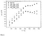
- FIG. 2 shows the Seebeck coefficients of the synthesized compounds as a function of the temperature
- FIG. 3 shows the electric conductivity of the synthesized compounds as a function of the temperature
- FIG. 4 shows the thermal conductivity of the synthesized compounds as a function of the temperature
- FIG. 5 shows the zT factors of the synthesized compounds as a function of the temperature.
- the evacuated ampoules were sealed and subjected to a temperature program in a tubular furnace. At first, with 50° C./h it was heated to 400° C., and this temperature was maintained for 36 hours, subsequently with 50° C./h it was heated to 850° C., and this temperature was maintained for 72 hours, and then it was cooled to room temperature with a cooling rate of 100° C./h. Temperatures of higher than 850° C. resulted in the formation of Cu 3 P and Mg 3 P 2 as secondary phases. A larger excess of magnesium resulted in the formation of Mg 2 Cu. It has been shown that the obtained preparations of Mg 1-x Mn x CuP were not air- or humidity-sensitive.
- the compaction was conducted with the help of SPS.
- Ca. 0.6 to 0.8 g of the samples each were finely pulverized and placed in a female graphite mold with an inner diameter of 10 mm.
- the pressing parameters were determined by a plurality of experiments.
- test pieces were obtained as follows. At first, without pressure with ca. 50° C./min it was heated to ca. 400° C. Then a pressure of 30 MPa (corresponds to 2.3 kN) was applied and it was further heated. At 650° C. the pressure was increased to 50 MPa (corresponds to 3.7 kN), and at constant temperature it was maintained for a period of time of half an hour. After the completion of the compaction and the shutdown of the power of the SPS apparatus no pressure was applied onto the test piece. In the context of this work in many compaction experiments was found that it is possible that the test pieces of intermetallic phases break, when during the cooling phase pressure is applied onto them.
- the female graphite molds were removed. With the help of a bench vise the samples were removed from the female molds, because it was difficult to loosen them from the female graphite mold. Thoroughly the compacted test pieces were mechanically treated with sand paper for removing optionally present graphite and for guaranteeing a good contact of the test pieces in the apparatuses for the determination of the thermoelectric properties. The densities of the samples were determined by pycnometry. Here, values of >95% of the theoretical, crystallographic density were measured.
- the obtained compacted test pieces of the solid solution Mg 1-x Mn x CuP were analyzed with X-ray diffraction in reflection for examining, whether the compaction had changed the sample. Diffractograms have shown that no changes in crystal structure had been caused by the compaction. After the compaction the samples have shown no change in identity.
- the compound Mg 0.90 Mn 0.10 CuP was analyzed thermoanalytically by means of DSC/TG ( FIG. 1 ). The measurement was performed under argon in platinum crucibles with internal corundum crucibles at temperatures of 25° C. to 700° C. with a heating rate of 10° C./min. No changes of the mass or peaks which are indicative for a physical or chemical conversion of the compound can be seen. Thus, the compound is thermostable.
- the measurements of the Seebeck coefficients show that MgCuP and the quaternary compounds are p-thermoelectric substances.
- the course of the Seebeck coefficients is similar for all compounds.
- the Seebeck coefficients strongly increase up to ca. 450° C.
- Mg 0.90 Mn 0.10 CuP and Mg 0.85 Mn 0.15 CuP show further increasing Seebeck coefficients without a maximum and with a value of 165 ⁇ V/K at 680° C.
- MgCuP and Mg 0.90 Mn 0.20 CuP decreasing Seebeck coefficients can be seen. But in the case of MgCuP the Seebeck coefficient again increases at temperatures of higher than 600° C.
- the thermal conductivities of Mg 1-x Mn x CuP were calculated on the basis of the thermal capacities of Mg 0.90 Mn 0.10 CuP which were measured by means of DSC ( FIG. 4 ). All compounds show considerable changes at a temperature of ca. 400° C. Up to 400° C. the thermal conductivities decrease, above 400° C. the thermal conductivities increase. MgCuP with values of 2.4 to 3.2 W/mK shows the highest thermal conductivities. Mg 0.90 Mn 0.10 CuP and Mg 0.85 Mn 0.15 CuP have the lowest values which above 600° C. are approximately constant. The substitution of Mn for Mg has resulted in lower thermal conductivities.
- thermoelectric figures of merit The high Seebeck coefficients, the relatively high electric conductivities and the low thermal conductivities result in high thermoelectric figures of merit (zT factors) which increase with the temperature ( FIG. 5 ).
- the zT factors of all compounds do not show a maximum.
- MgCuP and Mg 0.80 Mn 0.20 CuP have zT values of ca. 0.3 at 650° C. With the substitution of Mn for Mg a significant improvement of the thermoelectric properties was achieved.
- Mg 0.90 Mn 0.10 CuP and Mg 0.85 Mn 0.15 CuP with zT values of higher than 0.6 have factors of merit which are comparable with the zT values of the best phosphides described in literature till today.
Landscapes
- Chemical & Material Sciences (AREA)
- Inorganic Chemistry (AREA)
- Organic Chemistry (AREA)
- Inorganic Compounds Of Heavy Metals (AREA)
- Powder Metallurgy (AREA)
Applications Claiming Priority (3)
| Application Number | Priority Date | Filing Date | Title |
|---|---|---|---|
| DE102016116248.5A DE102016116248A1 (de) | 2016-08-31 | 2016-08-31 | Thermoelektrisches Material |
| DE102016116248.5 | 2016-08-31 | ||
| PCT/EP2017/071570 WO2018041788A1 (de) | 2016-08-31 | 2017-08-28 | Thermoelektrisches material |
Publications (2)
| Publication Number | Publication Date |
|---|---|
| US20190207072A1 US20190207072A1 (en) | 2019-07-04 |
| US11114601B2 true US11114601B2 (en) | 2021-09-07 |
Family
ID=59829342
Family Applications (1)
| Application Number | Title | Priority Date | Filing Date |
|---|---|---|---|
| US16/329,022 Active 2038-11-15 US11114601B2 (en) | 2016-08-31 | 2017-08-28 | Thermoelectric material |
Country Status (5)
| Country | Link |
|---|---|
| US (1) | US11114601B2 (de) |
| EP (1) | EP3507241B1 (de) |
| CN (1) | CN109641750B (de) |
| DE (1) | DE102016116248A1 (de) |
| WO (1) | WO2018041788A1 (de) |
Citations (6)
| Publication number | Priority date | Publication date | Assignee | Title |
|---|---|---|---|---|
| US7728218B2 (en) | 2005-09-07 | 2010-06-01 | California Institute Of Technology | High efficiency thermoelectric power generation using Zintl-type materials |
| US20110020164A1 (en) | 2009-07-27 | 2011-01-27 | Basf Se | Process for sintering thermoelectric materials |
| US20120091404A1 (en) | 2010-10-19 | 2012-04-19 | California Institute Of Technology | Zintl phases for thermoelectric applications |
| US20120128017A1 (en) | 2010-11-18 | 2012-05-24 | The Board Of Trustees Of The Leland Stanford Junior University | Electrical Devices Formed using Ternary Semiconducting Compounds |
| DE102011016808A1 (de) | 2011-04-13 | 2012-10-18 | Emitec Gesellschaft Für Emissionstechnologie Mbh | Vorrichtung mit einem Wärmetauscher für einen thermoelektrischen Generator eines Kraftfahrzeugs |
| DE102014203176A1 (de) | 2014-02-21 | 2015-09-10 | MAHLE Behr GmbH & Co. KG | Thermoelektrische Vorrichtung, insbesondere thermoelektrischer Generator oder Wärmepumpe |
Family Cites Families (3)
| Publication number | Priority date | Publication date | Assignee | Title |
|---|---|---|---|---|
| CN101101954A (zh) * | 2007-07-16 | 2008-01-09 | 中国科学院上海硅酸盐研究所 | 一种镉锑基p型热电材料及其制备方法 |
| CN101723669A (zh) * | 2008-10-31 | 2010-06-09 | 中国科学院上海硅酸盐研究所 | 一类可用于热电材料化合物及制备方法 |
| CN101429676A (zh) * | 2008-11-07 | 2009-05-13 | 同济大学 | 一种津特尔相单晶的制备方法 |
-
2016
- 2016-08-31 DE DE102016116248.5A patent/DE102016116248A1/de not_active Withdrawn
-
2017
- 2017-08-28 CN CN201780052481.2A patent/CN109641750B/zh active Active
- 2017-08-28 US US16/329,022 patent/US11114601B2/en active Active
- 2017-08-28 EP EP17764531.4A patent/EP3507241B1/de active Active
- 2017-08-28 WO PCT/EP2017/071570 patent/WO2018041788A1/de not_active Ceased
Patent Citations (9)
| Publication number | Priority date | Publication date | Assignee | Title |
|---|---|---|---|---|
| US7728218B2 (en) | 2005-09-07 | 2010-06-01 | California Institute Of Technology | High efficiency thermoelectric power generation using Zintl-type materials |
| US20110020164A1 (en) | 2009-07-27 | 2011-01-27 | Basf Se | Process for sintering thermoelectric materials |
| WO2011012548A2 (de) | 2009-07-27 | 2011-02-03 | Basf Se | Verfahren zum sintern von thermoelektrischen materialien |
| US20120091404A1 (en) | 2010-10-19 | 2012-04-19 | California Institute Of Technology | Zintl phases for thermoelectric applications |
| US20120128017A1 (en) | 2010-11-18 | 2012-05-24 | The Board Of Trustees Of The Leland Stanford Junior University | Electrical Devices Formed using Ternary Semiconducting Compounds |
| DE102011016808A1 (de) | 2011-04-13 | 2012-10-18 | Emitec Gesellschaft Für Emissionstechnologie Mbh | Vorrichtung mit einem Wärmetauscher für einen thermoelektrischen Generator eines Kraftfahrzeugs |
| US20140033703A1 (en) | 2011-04-13 | 2014-02-06 | Emitec Gesellschaft Fuer Emissionstechnologie Mbh | Device having a heat exchanger for a thermoelectric generator of a motor vehicle and motor vehicle having the device |
| DE102014203176A1 (de) | 2014-02-21 | 2015-09-10 | MAHLE Behr GmbH & Co. KG | Thermoelektrische Vorrichtung, insbesondere thermoelektrischer Generator oder Wärmepumpe |
| US20160245556A1 (en) | 2014-02-21 | 2016-08-25 | MAHLE Behr GmbH & Co. KG | Thermoelectric device, in particular thermoelectric generator or heat pump |
Non-Patent Citations (4)
| Title |
|---|
| Guechi, N. [et al.]: "Structural, elastic, electronic and optical properties of the newly synthesized monoclinic Zintl phase BaIn2P2", In: Solid State Sci., vol. 29, 2014, p. 12-23. |
| Ponnambalam, V. [et al.]: "High Seebeck coefficient AMXP2 (A=Ca and Yb; M, X=Zn, Cu and Mn) Zintl phosphides as high-temperature thermoe-lectric materials.", In: J. Phys D: Appl. Phys, vol. 44, 2011, No. 15, p. 155406 (pp. 6). |
| Ponnambalam, V. [et al.]: "Thermoelectric Properties of Light-Element-Containing Zintl Compounds CaZn2—xCuxP2 and CaMnZn1—xCuxP2 (x=0.0-0.2)", In: J. Electron. Mater., vol. 43, No. 6, 2014, S. 1875-1880. |
| Rauscher, Japheth F, [et al.]:"Flux growth and structure of two com-pounds with the EuIn2P2 structure type, AIn2P2 (A=Ca and Sr), and a new structure type BaIn2P2", In: Acta Cryst., Sect. C, Cryst. Struct. Commun., vol. 65, 2009, No. 10, p. i69-i73. |
Also Published As
| Publication number | Publication date |
|---|---|
| CN109641750A (zh) | 2019-04-16 |
| DE102016116248A1 (de) | 2018-03-01 |
| EP3507241B1 (de) | 2022-03-09 |
| US20190207072A1 (en) | 2019-07-04 |
| WO2018041788A1 (de) | 2018-03-08 |
| EP3507241A1 (de) | 2019-07-10 |
| CN109641750B (zh) | 2022-05-27 |
Similar Documents
| Publication | Publication Date | Title |
|---|---|---|
| US20100282285A1 (en) | Extrusion process for preparing improved thermoelectric materials | |
| Hu et al. | Synthesis of Mg2Si for thermoelectric applications using magnesium alloy and spark plasma sintering | |
| Søndergaard et al. | Thermoelectric Properties of the Entire Composition Range in Mg2Si0. 9925− x Sn x Sb0. 0075 | |
| EP2250126A2 (de) | Dotierte zinntelluride für thermoelektrische anwendungen | |
| Chetty et al. | The effect of Cu addition on the thermoelectric properties of Cu2CdGeSe4 | |
| Isachenko et al. | Thermoelectric Properties of Nanostructured p-Mg2Si x Sn1− x (x= 0.2 to 0.4) Solid Solutions | |
| Tiwari et al. | Ball mill synthesis of bulk quaternary Cu2ZnSnSe4 and thermoelectric studies | |
| US11114601B2 (en) | Thermoelectric material | |
| JP5099976B2 (ja) | 熱電変換材料の製造方法 | |
| US20230284532A1 (en) | Alloy, sintered article, thermoelectric module and method for the production of a sintered article | |
| JP6632218B2 (ja) | クラスレート化合物ならびに熱電変換材料およびその製造方法 | |
| WO2021235371A1 (ja) | 珪化物系合金材料及びそれを用いた素子 | |
| Zhang et al. | Ultrafast and low-cost preparation of Mg2 (Si0. 3Sn0. 7) 1− ySby with superior thermoelectric performance by self-propagating high-temperature synthesis | |
| KR20120035793A (ko) | 마그네슘 실리사이드계 열전재료의 제조방법 | |
| JP5090939B2 (ja) | p型熱電変換材料 | |
| JP6560061B2 (ja) | 熱電変換材料、熱電変換素子、熱電変換モジュールおよび熱電変換材料の製造方法 | |
| Nakamura et al. | Mg2Si thermoelectric device fabrication with reused-silicon | |
| KR20110092762A (ko) | 기계적 합금화에 의한 Mg2Si 열전재료 제조방법 및 이에 의해 제조된 Mg2Si 열전재료 | |
| JP6877814B2 (ja) | 熱電材料およびこれを含む熱電素子 | |
| JP5448942B2 (ja) | 熱電変換材料 | |
| Ding et al. | Effects of Synthesis Temperature on the Microstructure and Thermoelectric Properties of Te-Se Codoped Skutterudites | |
| Shin et al. | Thermoelectric properties of double-filled Pr1-z Nd z Fe4-x Co x Sb12 skutterudites | |
| CN115036412B (zh) | 一种三元层状热电材料及其制备方法 | |
| Park et al. | Effects of heat treatment on the thermoelectric properties of Yb-filled skutterudites | |
| Yamada et al. | Low‐temperature preparation and thermoelectric properties of CrSi2, MnSi1. 7+ δ, and CoSi using a Na flux |
Legal Events
| Date | Code | Title | Description |
|---|---|---|---|
| FEPP | Fee payment procedure |
Free format text: ENTITY STATUS SET TO UNDISCOUNTED (ORIGINAL EVENT CODE: BIG.); ENTITY STATUS OF PATENT OWNER: SMALL ENTITY |
|
| FEPP | Fee payment procedure |
Free format text: ENTITY STATUS SET TO SMALL (ORIGINAL EVENT CODE: SMAL); ENTITY STATUS OF PATENT OWNER: SMALL ENTITY |
|
| AS | Assignment |
Owner name: TECHNISCHE UNIVERSITAET DARMSTADT, GERMANY Free format text: ASSIGNMENT OF ASSIGNORS INTEREST;ASSIGNORS:ALBERT, BARBARA;HENGE, DENNIS;SIGNING DATES FROM 20190301 TO 20190315;REEL/FRAME:048740/0192 |
|
| STPP | Information on status: patent application and granting procedure in general |
Free format text: DOCKETED NEW CASE - READY FOR EXAMINATION |
|
| STPP | Information on status: patent application and granting procedure in general |
Free format text: NOTICE OF ALLOWANCE MAILED -- APPLICATION RECEIVED IN OFFICE OF PUBLICATIONS |
|
| STPP | Information on status: patent application and granting procedure in general |
Free format text: PUBLICATIONS -- ISSUE FEE PAYMENT VERIFIED |
|
| STCF | Information on status: patent grant |
Free format text: PATENTED CASE |
|
| MAFP | Maintenance fee payment |
Free format text: PAYMENT OF MAINTENANCE FEE, 4TH YR, SMALL ENTITY (ORIGINAL EVENT CODE: M2551); ENTITY STATUS OF PATENT OWNER: SMALL ENTITY Year of fee payment: 4 |