US11072161B2 - Extracting 3D objects - Google Patents
Extracting 3D objects Download PDFInfo
- Publication number
- US11072161B2 US11072161B2 US16/075,094 US201616075094A US11072161B2 US 11072161 B2 US11072161 B2 US 11072161B2 US 201616075094 A US201616075094 A US 201616075094A US 11072161 B2 US11072161 B2 US 11072161B2
- Authority
- US
- United States
- Prior art keywords
- platform
- build
- cake
- build material
- extraction
- Prior art date
- Legal status (The legal status is an assumption and is not a legal conclusion. Google has not performed a legal analysis and makes no representation as to the accuracy of the status listed.)
- Active, expires
Links
Images


Classifications
-
- B—PERFORMING OPERATIONS; TRANSPORTING
- B29—WORKING OF PLASTICS; WORKING OF SUBSTANCES IN A PLASTIC STATE IN GENERAL
- B29C—SHAPING OR JOINING OF PLASTICS; SHAPING OF MATERIAL IN A PLASTIC STATE, NOT OTHERWISE PROVIDED FOR; AFTER-TREATMENT OF THE SHAPED PRODUCTS, e.g. REPAIRING
- B29C64/00—Additive manufacturing, i.e. manufacturing of three-dimensional [3D] objects by additive deposition, additive agglomeration or additive layering, e.g. by 3D printing, stereolithography or selective laser sintering
- B29C64/10—Processes of additive manufacturing
- B29C64/141—Processes of additive manufacturing using only solid materials
- B29C64/153—Processes of additive manufacturing using only solid materials using layers of powder being selectively joined, e.g. by selective laser sintering or melting
-
- B—PERFORMING OPERATIONS; TRANSPORTING
- B08—CLEANING
- B08B—CLEANING IN GENERAL; PREVENTION OF FOULING IN GENERAL
- B08B5/00—Cleaning by methods involving the use of air flow or gas flow
- B08B5/04—Cleaning by suction, with or without auxiliary action
-
- B—PERFORMING OPERATIONS; TRANSPORTING
- B08—CLEANING
- B08B—CLEANING IN GENERAL; PREVENTION OF FOULING IN GENERAL
- B08B7/00—Cleaning by methods not provided for in a single other subclass or a single group in this subclass
- B08B7/02—Cleaning by methods not provided for in a single other subclass or a single group in this subclass by distortion, beating, or vibration of the surface to be cleaned
-
- B—PERFORMING OPERATIONS; TRANSPORTING
- B29—WORKING OF PLASTICS; WORKING OF SUBSTANCES IN A PLASTIC STATE IN GENERAL
- B29C—SHAPING OR JOINING OF PLASTICS; SHAPING OF MATERIAL IN A PLASTIC STATE, NOT OTHERWISE PROVIDED FOR; AFTER-TREATMENT OF THE SHAPED PRODUCTS, e.g. REPAIRING
- B29C64/00—Additive manufacturing, i.e. manufacturing of three-dimensional [3D] objects by additive deposition, additive agglomeration or additive layering, e.g. by 3D printing, stereolithography or selective laser sintering
- B29C64/10—Processes of additive manufacturing
- B29C64/165—Processes of additive manufacturing using a combination of solid and fluid materials, e.g. a powder selectively bound by a liquid binder, catalyst, inhibitor or energy absorber
-
- B—PERFORMING OPERATIONS; TRANSPORTING
- B29—WORKING OF PLASTICS; WORKING OF SUBSTANCES IN A PLASTIC STATE IN GENERAL
- B29C—SHAPING OR JOINING OF PLASTICS; SHAPING OF MATERIAL IN A PLASTIC STATE, NOT OTHERWISE PROVIDED FOR; AFTER-TREATMENT OF THE SHAPED PRODUCTS, e.g. REPAIRING
- B29C64/00—Additive manufacturing, i.e. manufacturing of three-dimensional [3D] objects by additive deposition, additive agglomeration or additive layering, e.g. by 3D printing, stereolithography or selective laser sintering
- B29C64/20—Apparatus for additive manufacturing; Details thereof or accessories therefor
- B29C64/245—Platforms or substrates
-
- B—PERFORMING OPERATIONS; TRANSPORTING
- B29—WORKING OF PLASTICS; WORKING OF SUBSTANCES IN A PLASTIC STATE IN GENERAL
- B29C—SHAPING OR JOINING OF PLASTICS; SHAPING OF MATERIAL IN A PLASTIC STATE, NOT OTHERWISE PROVIDED FOR; AFTER-TREATMENT OF THE SHAPED PRODUCTS, e.g. REPAIRING
- B29C64/00—Additive manufacturing, i.e. manufacturing of three-dimensional [3D] objects by additive deposition, additive agglomeration or additive layering, e.g. by 3D printing, stereolithography or selective laser sintering
- B29C64/30—Auxiliary operations or equipment
- B29C64/35—Cleaning
-
- B—PERFORMING OPERATIONS; TRANSPORTING
- B29—WORKING OF PLASTICS; WORKING OF SUBSTANCES IN A PLASTIC STATE IN GENERAL
- B29C—SHAPING OR JOINING OF PLASTICS; SHAPING OF MATERIAL IN A PLASTIC STATE, NOT OTHERWISE PROVIDED FOR; AFTER-TREATMENT OF THE SHAPED PRODUCTS, e.g. REPAIRING
- B29C64/00—Additive manufacturing, i.e. manufacturing of three-dimensional [3D] objects by additive deposition, additive agglomeration or additive layering, e.g. by 3D printing, stereolithography or selective laser sintering
- B29C64/40—Structures for supporting 3D objects during manufacture and intended to be sacrificed after completion thereof
-
- B—PERFORMING OPERATIONS; TRANSPORTING
- B33—ADDITIVE MANUFACTURING TECHNOLOGY
- B33Y—ADDITIVE MANUFACTURING, i.e. MANUFACTURING OF THREE-DIMENSIONAL [3-D] OBJECTS BY ADDITIVE DEPOSITION, ADDITIVE AGGLOMERATION OR ADDITIVE LAYERING, e.g. BY 3-D PRINTING, STEREOLITHOGRAPHY OR SELECTIVE LASER SINTERING
- B33Y10/00—Processes of additive manufacturing
-
- B—PERFORMING OPERATIONS; TRANSPORTING
- B33—ADDITIVE MANUFACTURING TECHNOLOGY
- B33Y—ADDITIVE MANUFACTURING, i.e. MANUFACTURING OF THREE-DIMENSIONAL [3-D] OBJECTS BY ADDITIVE DEPOSITION, ADDITIVE AGGLOMERATION OR ADDITIVE LAYERING, e.g. BY 3-D PRINTING, STEREOLITHOGRAPHY OR SELECTIVE LASER SINTERING
- B33Y30/00—Apparatus for additive manufacturing; Details thereof or accessories therefor
-
- B—PERFORMING OPERATIONS; TRANSPORTING
- B33—ADDITIVE MANUFACTURING TECHNOLOGY
- B33Y—ADDITIVE MANUFACTURING, i.e. MANUFACTURING OF THREE-DIMENSIONAL [3-D] OBJECTS BY ADDITIVE DEPOSITION, ADDITIVE AGGLOMERATION OR ADDITIVE LAYERING, e.g. BY 3-D PRINTING, STEREOLITHOGRAPHY OR SELECTIVE LASER SINTERING
- B33Y40/00—Auxiliary operations or equipment, e.g. for material handling
- B33Y40/20—Post-treatment, e.g. curing, coating or polishing
-
- G—PHYSICS
- G06—COMPUTING; CALCULATING OR COUNTING
- G06F—ELECTRIC DIGITAL DATA PROCESSING
- G06F30/00—Computer-aided design [CAD]
Definitions
- Additive manufacturing processes can produce three-dimensional (3D) objects by providing a layer-by-layer accumulation and solidification of build material patterned from a digital model.
- layers of build material are processed using heat to cause melting and solidification of the material in selected regions of each layer.
- the selected regions comprise 2D cross-sectional areas that represent a 3D slice of an object being formed, or printed.
- layers of build material can be preheated prior to the melting process.
- the selected regions can be defined by depositing a fusing agent that helps to absorb heat to melt the material within the selected regions.
- such additive manufacturing processes can result in a solidified 3D object encased within a block or “cake” of build material that can be bound together with varying degrees of firmness.
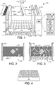
- FIG. 1 shows a perspective view of an example extraction system for extracting 3D objects from a powder build cake
- FIG. 2 shows an example of a build cake that has been deposited and processed in a container
- FIG. 3 shows an example of an extraction platform being vibrated to break apart powdered build material from a build cake
- FIG. 4 shows an example of an extraction platform implemented as a screen platform with a course screen grid of crossed wires
- FIG. 5 shows a flow diagram of an example method of extracting 3D objects.
- the result is a build volume comprising a block of heated build material that contains solidified 3D objects within the block.
- blocks of build material can be produced, for example, with powder-based printing systems that implement a layer-by-layer accumulation and solidification of powdered build material.
- the build material used to print 3D objects in such layer-by-layer 3D printing processes can include various powdered materials such as polystyrene, ceramics, glass, nylon, and metals including steel, titanium, aluminum, and silver.
- a block of build material containing a 3D object may therefore be alternately referred to herein as a “cake”, a “powder cake”, a “build cake”, a “powdered build cake”, and the like.
- the strength or firmness of the powder cake surrounding the 3D object can depend on various factors associated with the particular printing process used to generate the cake. Such factors can include, for example, the type of powdered build material used, the amount of preheat applied to the layers of build material, the amount of heat applied to melt selected regions of build material layers, and so on.
- the cake in addition to a fully fused and solidified 3D object, the cake may comprise a continuum of build material that ranges in firmness from loosely bound powder to weakly fused powder.
- the cake may comprise more firmly fused powder in areas closer to the 3D object that have been exposed to higher levels of heat during printing.
- extracting 3D objects from the heated powder cake can involve a number of post printing steps.
- an initial post printing step can include allowing time for the heated cake to cool off before extracting the objects.
- the cake can be removed from the printing system and placed in a cool environment to help speed the cooling.
- a next step in extracting a 3D object can include digging into the loose powder and carefully removing the object by hand.
- a next step can include physically fracturing the cake to help the cake cool faster and to break pieces of the cake away from the 3D object or objects.
- Other post printing steps can include cleaning the 3D objects using pressurized air to remove the remaining fine powder, polishing surfaces of the objects, applying a coating to the surfaces of the objects, and so on.
- post printing processes can involve significant human interaction with the powder cake.
- the cake prior to breaking apart a cake comprising partially fused powder, the cake can be physically removed from the 3D printing device and relocated to a setting that is conducive to applying mechanisms to the cake that can cause the cake to break apart.
- Such mechanisms have generally included various types of hand held instruments such as hammers, trowels, brushes, and so on. These and other instruments can be used to further break up the cake into smaller and smaller pieces so that the powder can be cleared away from the 3D object or objects.
- Such post printing processes can add significant time, labor, and cost to the creation of 3D printed parts.
- a system employs a vibratory extraction platform that can vibrate a powder build cake, creating stress points within the cake that help to fracture the cake.
- the extraction platform comprises a sieve surface that can grate through the cake as the platform vibrates. The sieve platform can mechanically shear small pieces of the cake away and sift the small pieces of powdered build material through the platform.
- the cake can either be transferred to the vibratory extraction platform from a 3D printing system, or it can be formed on the vibratory extraction platform within a 3D printing system.
- a system employs an impulse mechanism that can apply an impulse to a powder cake, and/or to a container holding the powder cake, in order to create cracks in the cake.
- the impulse creates a high shock or g-force through the cake through an impact mechanism such as a linear motor, a solenoid, or a geared release system.
- a system for extracting a 3D object can comprise an independent system that stands alone and receives a powder build cake transferred from a 3D printing device for post print processing.
- a system for extracting a 3D object can comprise an integral part of a 3D printing system in which a powder build cake is formed in the 3D printing system and remains in the 3D printing system for post print processing. In either case, a system for extracting a 3D object enables automation of various extraction steps that can significantly reduce the time and effort involved in extracting 3D objects from powder cakes.
- cracking a powdered build cake with an impulse, or breaking it apart using a vibratory platform can significantly reduce the time it takes for the cake to cool, which enables a faster extraction of a 3D object from the cake.
- the cake can be allowed to cool prior to applying an impulse in order to improve cracking of the cake.
- vibrating a powder cake on an extraction platform to shear away powdered build material and sift the material through the platform can reduce the time it takes to extract a 3D part from a cake as well as reduce the effort otherwise involved in retrieving the part.
- a method of extracting 3D objects includes forming on a vibratory extraction platform, a build cake that comprises a fused 3D object encased within build material, and vibrating the extraction platform to break apart the build material and sift the material through openings in the extraction platform.
- a system for extracting 3D objects includes a work area to contain a build cake that comprises a fused 3D object encased within powdered build material.
- the vibratory extraction platform forms a floor to the work area.
- the system includes a vibration device to vibrate the extraction platform to break apart the build material and sift it through openings in the extraction platform.
- the work area comprises a work area within a 3D printing device where the build cake is formed.
- the work area comprises a work area within an independent extraction system to which the build cake can be transferred.
- a device for extracting 3D objects includes a 3D printing system to form a 3D object on an extraction platform.
- the 3D object is to be formed within a cake comprising build material.
- the device also includes a vibration device to vibrate the extraction platform. Vibrating the extraction platform is to break apart the cake and cause build material to sift through openings in the extraction platform.
- FIG. 1 shows a perspective view of an example extraction system 100 for extracting 3D objects from a powder build cake.
- the example extraction system 100 is implemented as a powder-based 3D printing system 100 that forms 3D objects through a process that includes a layer-by-layer accumulation and solidification of powdered build material.
- the example system 100 can provide a 3D printing function to form a powder build cake comprising a 3D object, in addition to providing an extraction function to extract the 3D object from the powder build cake.
- the process of forming a build cake can vary depending on the additive manufacturing process being used.
- one example process for producing/printing a 3D object within a build cake is generally described herein, other powder-based processes are possible and contemplated.
- Such powder-based 3D printing processes can include, for example, selective laser sintering, selective laser melting, and binder jetting.
- an extraction system 100 can be implemented as an independent extraction device that provides an extraction function independent of a 3D printing function.
- the extraction system can receive a powder build cake previously formed in a separate 3D printing device and extract a 3D object from the powder build cake.
- the example system 100 includes a moveable printing platform 102 , or build platform 102 , that can serve as a floor to a work space 104 in which a 3D object (not shown in FIG. 1 ) can be printed.
- the platform comprises a vibratory extraction platform 102 that includes openings 103 discussed herein below. Because the platform 102 can perform multiple functions, the platform 102 may be referred to alternately herein as a printing platform 102 , a build platform 102 , an extraction platform 102 , a vibratory extraction platform 102 , a sieve platform 102 , and so on.
- the work space 104 can be located within a build container 109 comprising walls 105 (illustrated as front wall 105 a (shown as transparent), side wall 105 b , back wall 105 c , side wall 105 d ), where the build platform 102 , or vibratory extraction platform 102 , serves as a floor to the build container 109 .
- the extraction platform 102 can be rigidly attached to the walls 105 of the build container 109 such that when the extraction platform 102 is vibrated, the entire build container 109 vibrates. In other examples, the extraction platform 102 may not be attached to the walls 105 of the build container 109 . As shown in FIG.
- the build container 109 and platform 102 can contain a volume 106 of powdered build material that has been deposited into the work space 104 and heated in a layer by layer 3D print process during printing of a 3D object 107 .
- the volume of powdered build material can be referred to alternately as a “cake” 106 , a “powder cake” 106 , a “build cake” 106 , a “powdered build cake” 106 , and the like.
- FIG. 2 shows an example of a build cake 106 that has been formed in a layer by layer process within a build container 109 .
- the build cake 106 is shown resting on a vibratory extraction platform 102 .
- the vibratory extraction platform 102 can comprise an integral part of a 3D printing system 100 as shown in FIG. 1 .
- the vibratory extraction platform 102 comprises a build platform 102 on which the build cake 106 is formed.
- the vibratory extraction platform 102 can comprise part of an independent extraction system for extracting 3D objects from a powder build cake 106 .
- a build cake 106 is not formed on the extraction platform 102 , but can instead be transferred to the extraction platform to extract a 3D object from the build cake 106 .
- a build cake 106 can be formed within the work space 104 of build container 109 .
- the build cake 106 can include a 3D object 107 shown with dashed lines in FIG. 2 to indicate its location within the volume of the build cake 106 .
- a 3D object 107 can be formed by layers of powdered build material 108 that have each been spread over the platform 102 by a material spreader 110 (e.g., a roller, a blade, etc.), and subsequently processed by depositing a liquid fusing agent 112 from a liquid agent dispenser 114 and by applying heat from a heat source 116 .
- a material spreader 110 e.g., a roller, a blade, etc.
- a dispenser 114 can be implemented as a print bar comprising multiple drop-on-demand printheads such as thermal inkjet and/or piezoelectric inkjet printheads.
- a carriage (not shown) can be associated with the dispenser 114 to convey the dispenser 114 over the platform 102 in a scanning motion (illustrated by direction arrow 118 ) during the application of liquid agent 112 onto a layer of build powder on the platform 102 .
- Heat source 116 can be implemented as a radiation source 116 to provide fusing energy R (e.g., radiation) to melt selected regions of each layer of build powder.
- the heat source 116 can also be conveyed across the platform 102 in a scanning motion or some other motion.
- the finished build cake 106 can include a 3D object 107 encased within and supported by build powder that has been weakly fused together by heat generated during the printing process.
- the vibratory extraction platform 102 (i.e., build platform 102 ) is moveable within the work space 104 in an upward and downward direction as indicated by up arrow 120 and down arrow 122 , respectively.
- the platform 102 can be located in an upward position toward the top of the work space 104 as a first layer of powdered build material is deposited onto the platform 102 and processed. Accordingly, during formation of the build cake and 3D object(s), powdered material is applied from a top side of the work space 104 and build container 109 .
- multiple layers of powdered build material can be deposited onto the platform 102 as sacrificial layers prior to depositing and processing a first layer of 3D object to be printed.
- the sacrificial layers can be used to clog up the openings 103 in the platform 102 and create a stable surface on which to begin forming layers to build a 3D object 107 .
- the build material 108 can be powdered material with fine particle sizes, it should be apparent that the openings 103 shown in FIG. 1 are not drawn to scale.
- the openings 103 of a platform 102 can be small enough that when numerous particles land indirectly on and around the openings, they push against one another and prevent the entry of any particles through the openings, thus clogging the openings.
- a first layer of a 3D object to be printed can be deposited onto the last sacrificial layer.
- the platform 102 can move in a downward direction 122 as additional layers of powdered build material are deposited onto the platform 102 and processed.
- the extraction system 100 can include a vibration device, such as vibration devices 124 and 126 .
- the vibration devices can be coupled to the vibratory extraction platform 102 to vibrate the platform 102 in order to break apart build material from the build cake 106 and to sift the broken up build material through the openings 103 in the extraction platform 102 .
- a vibration device 124 can be employed to vibrate the extraction platform 102 in a horizontal direction
- a vibration device 126 can be employed to vibrate the extraction platform 102 in a vertical direction.
- the frequency, magnitude, and direction of vibration of the extraction platform 102 can be controlled by controlling the vibration devices 124 , 126 .
- a vibration device 124 , 126 can be implemented in various ways including, for example, as an eccentric rotating mass vibration motor (ERM) and a linear resonant actuator (LRA).
- ERP eccentric rotating mass vibration motor
- LRA linear resonant actuator
- FIG. 3 shows an example of an extraction platform 102 being vibrated to break apart powdered build material from the build cake 106 and to sift the broken up build material through the openings 103 in the extraction platform 102 .
- powdered build material can be applied from the top side of the build container 109 during formation of the build cake, as noted above, powdered material can be extracted from the bottom side of the build container 109 (i.e., through the platform 102 ) during vibration and break-up of the build cake.
- Vibration of the extraction platform 102 can create stress within the powder build cake 106 that causes the cake 106 to fracture, as indicated by the fracture lines 128 in FIG. 3 .
- fracturing the cake increases the surface area of the cake which can increase the cooling rate of the cake and of 3D objects within the cake.
- the vibratory extraction platform 102 can shear away small pieces of the cake and sift the small pieces of loose powdered build material 130 through the openings 103 in the platform 102 .
- the openings 103 in the extraction platform 102 can include a variety of different types of openings that facilitate the break up and/or shearing of the build cake 106 as the platform 102 is being vibrated by vibration devices 124 , 126 .
- the extraction platform 102 can comprise a sieve platform with holes as shown generally in FIG. 1 , a screen platform with a course screen grid of crossed wires as shown in FIG. 4 , a labyrinth platform comprising an irregular network of passages, a grater platform comprising a surface covered with holes having slightly raised cutting edges, and so on.
- an extraction system 100 can also include a particle collection area 132 to collect loose powdered build material 130 that has been broken away from and/or sheared off of the build cake 106 .
- the particle collection area 130 can include a particle collection container (not shown) to collect the powdered build material 130 falling from the force of gravity through the openings 103 in the extraction platform 102 .
- an extraction system 100 can include a vacuum source 131 positioned, for example, below the extraction platform 102 to increase the rate of extraction of loose powder through the openings 103 and away from the cake 106 and 3D object 107 .
- the vacuum 131 can increase cooling of the cake and 3D object by generating air convection through the fracture lines 128 .
- the powder cake can increase in firmness as it cools over time, which can influence the timing for applying vibration or an impulse into the cake.
- an extraction system 100 can include an impulse generator 134 to apply an impulse to a powder build cake 106 .
- An impulse generator 134 can be employed to fracture the cake 106 prior to vibrating the cake on the extraction platform 102 . In some examples, fracturing the cake 106 can be useful to help speed the cooling of the cake prior to vibration.
- an impulse generator 134 can apply an impulse to the build container 109 that holds the powder build cake 106 .
- An impulse applied to the cake 106 or the build container 109 can impart a high level of g-force to the cake 106 that mechanically shocks the cake and transmits interior mechanical stress throughout the cake 106 , causing it to fracture.
- An impulse generator 134 can be implemented as a variety of different devices including, for example, a linear motor, a solenoid, and a geared-release system.
- the example extraction system 100 additionally includes an example controller 136 .
- the controller 136 can control various operations of the extraction system 100 to facilitate both the printing of 3D objects as generally described above, and the extraction of 3D objects from a powder build cake 106 containing 3D objects.
- an example controller 136 can include a processor (CPU) 138 and a memory 140 .
- the controller 136 may additionally include other electronics (not shown) for communicating with and controlling various components of the extraction system 100 .
- Such other electronics can include, for example, discrete electronic components and/or an ASIC (application specific integrated circuit).
- Memory 140 can include both volatile (i.e., RAM) and nonvolatile memory components (e.g., ROM, hard disk, optical disc, CD-ROM, magnetic tape, flash memory, etc.).
- the components of memory 140 can comprise non-transitory, machine-readable (e.g., computer/processor-readable) media that can provide for the storage of machine-readable coded program instructions, data structures, program instruction modules, JDF (job definition format), 3MF formatted data, and other data and/or instructions executable by a processor 138 of the extraction system 100 .
- volatile i.e., RAM
- nonvolatile memory components e.g., ROM, hard disk, optical disc, CD-ROM, magnetic tape, flash memory, etc.
- the components of memory 140 can comprise non-transitory, machine-readable (e.g., computer/processor-readable) media that can provide for the storage of machine-readable coded program instructions, data structures, program instruction modules, JDF (job definition format), 3MF formatted data, and other data and
- modules 142 and 144 include programming instructions executable by processor 138 to cause the extraction system 100 to perform operations related to printing 3D objects within a work space 104 , and extracting the 3D objects from a powder build cake 106 generated in the printing process.
- Such operations can include, for example, the operations of a method 500 , described below with respect to FIG. 5 .
- controller 136 can receive object data 146 from a host system such as a computer.
- Object data 146 can represent, for example, object files defining 3D object models to be produced in the extraction system 100 .
- Executing instructions from the build module 146 the processor 138 can generate print data for each cross-sectional slice of a 3D object model from the object data 146 .
- the print data can define, for example, each cross-sectional slice of a 3D object model, the liquid agents to be used to cover the build powder within each cross-sectional slice, and how fusing energy is to be applied to fuse each layer of powder build material.
- the processor 138 can use the print data to control printing components of the extraction system 100 to process each layer of build powder.
- the object data can be used to generate commands and/or command parameters for controlling the distribution of build powder 108 onto the extraction platform 102 by a spreader 110 , the application of fusing agents 112 by a print bar 114 onto layers of the powder, the application of radiation by a radiation source 116 to the layers of powder, and so on.
- the extraction module 144 includes further executable instructions to enable a processor 138 to control the extraction system 100 to perform an extraction of a 3D object 107 from a build cake 106 generated during a printing process. More specifically, extraction module instructions can execute to control vibration devices 124 and 126 to vibrate the vibratory extraction platform 102 in order to break apart build material from the build cake 106 and to sift the broken up build material through the openings 103 in the extraction platform 102 . The vibration devices 124 and 126 can be controlled to vibrate the extraction platform 102 in horizontal and vertical directions. The frequency, magnitude, and direction of vibration of the extraction platform 102 can also be controlled by controlling the vibration devices 124 , 126 .
- the extraction module instructions can also execute to enable a processor 138 to control an impulse generator 134 to apply an impulse to a powder build cake 106 (or the build container 109 containing the cake 106 ) to fracture the cake 106 prior to vibrating the extraction platform 102 .
- the impulse generator 134 can be controlled to apply varying levels of impulses to the cake 106 that can impart varying levels of g-force to the cake 106 that mechanically shock the cake and transmit interior mechanical stress through the cake 106 , causing it to fracture.
- the extraction module instructions can execute to determine different levels of impulses based on factors such as the type of powder build material of the cake 106 , the temperature of the cake 106 , the size and shape of the 3D objects contained within the cake 106 , and so on.
- FIG. 5 shows a flow diagram of an example method 500 of extracting 3D objects.
- the method 500 is associated with examples discussed above with regard to FIGS. 1-4 , and details of the operations shown in method 500 can be found in the related discussion of such examples.
- the operations of method 500 may be embodied as programming instructions stored on a non-transitory, machine-readable (e.g., computer/processor-readable) medium, such as memory 140 shown in FIG. 1 .
- implementing the operations of method 500 can be achieved by a processor, such as a processor 138 of FIG. 1 , reading and executing the programming instructions stored in a memory 140 .
- implementing the operations of method 500 can be achieved using an ASIC and/or other hardware components alone or in combination with programming instructions executable by a processor 138 .
- the method 500 may include more than one implementation, and different implementations of method 500 may not employ every operation presented in the flow diagram of FIG. 5 . Therefore, while the operations of method 500 are presented in a particular order within the flow diagram, the order of their presentation is not intended to be a limitation as to the order in which the operations may actually be implemented, or as to whether all of the operations may be implemented. For example, one implementation of method 500 might be achieved through the performance of a number of initial operations, without performing one or more subsequent operations, while another implementation of method 500 might be achieved through the performance of all of the operations.
- an example method 500 of extracting 3D objects begins at block 502 with forming on a vibratory extraction platform, a build cake comprising a fused 3D object encased within build material.
- forming a build cake on a vibratory extraction platform can include depositing sacrificial layers of build material onto the extraction platform to block the openings in the extraction platform, depositing a layer of build material over a last sacrificial layer, selectively depositing a fusing agent on the layer of build material, and applying heat to fuse the layer of build material into an integrated cross-sectional slice of the 3D object.
- the method 500 can continue as shown at block 512 with vibrating the extraction platform to break apart the build material and sift it through openings in the extraction platform.
- vibrating the extraction platform can include mechanically shearing build material off of the build cake into loose particles small enough to fit through the openings in the extraction platform, and pulling the loose particles through the openings with a vacuum.
- vibrating the extraction platform can include applying horizontal and vertical force to the extraction platform.
- applying a force to the extraction platform can include varying the frequency and magnitude of the force, as shown at block 518 .
- method 500 can include, applying an impulse to the build cake to fracture the build cake prior to vibrating the extraction platform, as shown at block 520 .
- a time delay can be implemented after applying an impulse, prior to vibrating the extraction platform. Such a delay can be useful, for example, to speed the cooling of the cake prior to vibration.
- applying an impulse to the build cake can include impacting the build container surrounding the build cake, as shown at block 522 .
Landscapes
- Engineering & Computer Science (AREA)
- Chemical & Material Sciences (AREA)
- Materials Engineering (AREA)
- Manufacturing & Machinery (AREA)
- Physics & Mathematics (AREA)
- Optics & Photonics (AREA)
- Mechanical Engineering (AREA)
- Theoretical Computer Science (AREA)
- Evolutionary Computation (AREA)
- Geometry (AREA)
- General Engineering & Computer Science (AREA)
- General Physics & Mathematics (AREA)
- Computer Hardware Design (AREA)
- Powder Metallurgy (AREA)
- Architecture (AREA)
- Software Systems (AREA)
Applications Claiming Priority (1)
| Application Number | Priority Date | Filing Date | Title |
|---|---|---|---|
| PCT/US2016/067912 WO2018118032A1 (fr) | 2016-12-21 | 2016-12-21 | Extraction d'objets 3d |
Publications (2)
| Publication Number | Publication Date |
|---|---|
| US20190039367A1 US20190039367A1 (en) | 2019-02-07 |
| US11072161B2 true US11072161B2 (en) | 2021-07-27 |
Family
ID=62627651
Family Applications (1)
| Application Number | Title | Priority Date | Filing Date |
|---|---|---|---|
| US16/075,094 Active 2037-08-10 US11072161B2 (en) | 2016-12-21 | 2016-12-21 | Extracting 3D objects |
Country Status (4)
| Country | Link |
|---|---|
| US (1) | US11072161B2 (fr) |
| EP (1) | EP3558642B1 (fr) |
| CN (1) | CN109715369A (fr) |
| WO (1) | WO2018118032A1 (fr) |
Families Citing this family (15)
| Publication number | Priority date | Publication date | Assignee | Title |
|---|---|---|---|---|
| US11491720B2 (en) * | 2018-02-07 | 2022-11-08 | Desktop Metal, Inc. | Systems, devices, and methods for additive manufacturing |
| US11167375B2 (en) | 2018-08-10 | 2021-11-09 | The Research Foundation For The State University Of New York | Additive manufacturing processes and additively manufactured products |
| JP7120122B2 (ja) | 2019-03-29 | 2022-08-17 | 新東工業株式会社 | 付加製造システム及び除去方法 |
| US10987866B2 (en) * | 2019-06-25 | 2021-04-27 | Hewlett-Packard Development Company, L.P. | Removing build material |
| US11951515B2 (en) | 2019-08-05 | 2024-04-09 | Desktop Metal, Inc. | Techniques for depowdering additively fabricated parts via gas flow and related systems and methods |
| US11833585B2 (en) | 2019-08-12 | 2023-12-05 | Desktop Metal, Inc. | Techniques for depowdering additively fabricated parts through vibratory motion and related systems and methods |
| CN111222262B (zh) * | 2019-10-30 | 2023-09-29 | 中国中元国际工程有限公司 | 基于质量比影响的气浮隔振平台性能优化设计方法 |
| JP7327891B2 (ja) | 2019-11-11 | 2023-08-16 | ダイハツ工業株式会社 | 積層造形方法及び積層造形装置 |
| US11865615B2 (en) | 2019-12-11 | 2024-01-09 | Desktop Metal, Inc. | Techniques for depowdering additively fabricated parts and related systems and methods |
| US20220371273A1 (en) * | 2020-01-30 | 2022-11-24 | Hewlett-Packard Development Company, L.P. | Additive manufacturing tray |
| CN112718473B (zh) * | 2020-12-21 | 2022-08-12 | 山东凤鸣桓宇环保有限公司 | 一种滤网清理结构 |
| CN112709061B (zh) * | 2020-12-22 | 2022-09-20 | 抚州市鸿源纺织科技有限公司 | 一种纺织设备 |
| CN112871822A (zh) * | 2020-12-25 | 2021-06-01 | 安徽工业大学 | 一种电气柜自动清洗方法 |
| CN113650300B (zh) * | 2021-08-16 | 2023-06-13 | 无锡东仪制造科技有限公司 | 分离装置及分离方法 |
| WO2024038408A1 (fr) * | 2022-08-18 | 2024-02-22 | Dei Holding Ltd | Appareil, système et procédé de dépoudrage et d'extraction automatisés de pièces imprimées tridimensionnelles |
Citations (23)
| Publication number | Priority date | Publication date | Assignee | Title |
|---|---|---|---|---|
| SU863173A1 (ru) | 1979-11-02 | 1981-09-15 | Украинский Государственный Проектный И Конструкторский Институт Машиностроительной И Станкоинструментальной Промышленности | Устройство дл выбивки литейных форм |
| SU1685599A1 (ru) | 1989-07-11 | 1991-10-23 | Научно-производственное объединение "Атомкотломаш" | Установка дл выбивки каркасов стержней |
| WO1995034468A1 (fr) | 1994-06-14 | 1995-12-21 | Soligen, Inc. | Appareil de manipulation de poudre pour equipement de fabrication par addition |
| US20010045678A1 (en) * | 2000-05-25 | 2001-11-29 | Minolta Co., Ltd. | Three-dimensional modeling apparatus |
| US20040025905A1 (en) | 2000-10-04 | 2004-02-12 | Ingo Ederer | Method for unpacking shaped bodies embedded inside unbound particle material |
| US20040084814A1 (en) | 2002-10-31 | 2004-05-06 | Boyd Melissa D. | Powder removal system for three-dimensional object fabricator |
| US6932935B1 (en) | 1999-08-06 | 2005-08-23 | Eos Gmbh Electro Optical Systems | Method and device for producing a three-dimensional object |
| US20070126157A1 (en) | 2005-12-02 | 2007-06-07 | Z Corporation | Apparatus and methods for removing printed articles from a 3-D printer |
| US20080241404A1 (en) | 2005-09-20 | 2008-10-02 | Sandrine Allaman | Apparatus for Building a Three-Dimensional Article and a Method for Building a Three-Dimensional Article |
| US20130244040A1 (en) | 2012-03-08 | 2013-09-19 | Casio Computer Co., Ltd. | Three-dimensional shaping method and shaped object complex as well as three-dimensional shaping apparatus |
| WO2014039378A1 (fr) | 2012-09-05 | 2014-03-13 | Aprecia Pharmaceuticals Company | Système d'impression tridimensionnelle et ensemble équipement |
| US8827681B2 (en) | 2010-08-31 | 2014-09-09 | Microjet Technology Co., Ltd | Automatic powder recycling apparatus |
| RU2535704C1 (ru) | 2013-04-18 | 2014-12-20 | Общество С Ограниченной Ответственностью "Группа "Магнезит" | Способ трехмерной печати огнеупорных изделий |
| CN204035537U (zh) | 2014-06-27 | 2014-12-24 | 江苏东吴新材料科技有限公司 | 辊压型除砂振动台 |
| CN104275491A (zh) | 2014-10-24 | 2015-01-14 | 合肥斯科尔智能科技有限公司 | 一种用于三维打印的金属粉回收系统 |
| US20150258744A1 (en) | 2012-07-09 | 2015-09-17 | Exone Gmbh | Method and Device for Unpacking a Component |
| US20160207265A1 (en) | 2012-09-05 | 2016-07-21 | Aprecia Pharmaceuticals Company | Three-dimensional Printing System and Equipment Assembly |
| US20160279871A1 (en) | 2013-11-15 | 2016-09-29 | Eos Gmbh Electro Optical Systems | Device for Producing a Three-Dimensional Object in Layers |
| US20170165751A1 (en) * | 2015-12-10 | 2017-06-15 | Velo3D, Inc. | Skillful Three-Dimensional Printing |
| WO2017188967A1 (fr) | 2016-04-29 | 2017-11-02 | Hewlett-Packard Development Company, L.P. | Impression en trois dimensions (3d) |
| US20180126620A1 (en) * | 2015-05-29 | 2018-05-10 | Philips Lighting Holding B.V. | 3d printing device and method |
| US20190176395A1 (en) * | 2016-05-12 | 2019-06-13 | Hewlett-Packard Development Company, L.P. | Post-processing in 3d printing systems |
| US10377061B2 (en) * | 2014-03-20 | 2019-08-13 | Shapeways, Inc. | Processing of three dimensional printed parts |
Family Cites Families (1)
| Publication number | Priority date | Publication date | Assignee | Title |
|---|---|---|---|---|
| DE102014112450A1 (de) * | 2014-08-29 | 2016-03-03 | Exone Gmbh | Beschichteranordnung für einen 3D-Drucker |
-
2016
- 2016-12-21 US US16/075,094 patent/US11072161B2/en active Active
- 2016-12-21 CN CN201680089431.7A patent/CN109715369A/zh active Pending
- 2016-12-21 EP EP16924415.9A patent/EP3558642B1/fr active Active
- 2016-12-21 WO PCT/US2016/067912 patent/WO2018118032A1/fr unknown
Patent Citations (26)
| Publication number | Priority date | Publication date | Assignee | Title |
|---|---|---|---|---|
| SU863173A1 (ru) | 1979-11-02 | 1981-09-15 | Украинский Государственный Проектный И Конструкторский Институт Машиностроительной И Станкоинструментальной Промышленности | Устройство дл выбивки литейных форм |
| SU1685599A1 (ru) | 1989-07-11 | 1991-10-23 | Научно-производственное объединение "Атомкотломаш" | Установка дл выбивки каркасов стержней |
| WO1995034468A1 (fr) | 1994-06-14 | 1995-12-21 | Soligen, Inc. | Appareil de manipulation de poudre pour equipement de fabrication par addition |
| US6932935B1 (en) | 1999-08-06 | 2005-08-23 | Eos Gmbh Electro Optical Systems | Method and device for producing a three-dimensional object |
| US20010045678A1 (en) * | 2000-05-25 | 2001-11-29 | Minolta Co., Ltd. | Three-dimensional modeling apparatus |
| US20040025905A1 (en) | 2000-10-04 | 2004-02-12 | Ingo Ederer | Method for unpacking shaped bodies embedded inside unbound particle material |
| US20040084814A1 (en) | 2002-10-31 | 2004-05-06 | Boyd Melissa D. | Powder removal system for three-dimensional object fabricator |
| US20080241404A1 (en) | 2005-09-20 | 2008-10-02 | Sandrine Allaman | Apparatus for Building a Three-Dimensional Article and a Method for Building a Three-Dimensional Article |
| US20070126157A1 (en) | 2005-12-02 | 2007-06-07 | Z Corporation | Apparatus and methods for removing printed articles from a 3-D printer |
| US8827681B2 (en) | 2010-08-31 | 2014-09-09 | Microjet Technology Co., Ltd | Automatic powder recycling apparatus |
| US20130244040A1 (en) | 2012-03-08 | 2013-09-19 | Casio Computer Co., Ltd. | Three-dimensional shaping method and shaped object complex as well as three-dimensional shaping apparatus |
| US20150258744A1 (en) | 2012-07-09 | 2015-09-17 | Exone Gmbh | Method and Device for Unpacking a Component |
| WO2014039378A1 (fr) | 2012-09-05 | 2014-03-13 | Aprecia Pharmaceuticals Company | Système d'impression tridimensionnelle et ensemble équipement |
| EP2892708A1 (fr) | 2012-09-05 | 2015-07-15 | Aprecia Pharmaceuticals Co. | Système d'impression tridimensionnelle et ensemble équipement |
| US20160207265A1 (en) | 2012-09-05 | 2016-07-21 | Aprecia Pharmaceuticals Company | Three-dimensional Printing System and Equipment Assembly |
| RU2535704C1 (ru) | 2013-04-18 | 2014-12-20 | Общество С Ограниченной Ответственностью "Группа "Магнезит" | Способ трехмерной печати огнеупорных изделий |
| US20160279871A1 (en) | 2013-11-15 | 2016-09-29 | Eos Gmbh Electro Optical Systems | Device for Producing a Three-Dimensional Object in Layers |
| US10377061B2 (en) * | 2014-03-20 | 2019-08-13 | Shapeways, Inc. | Processing of three dimensional printed parts |
| CN204035537U (zh) | 2014-06-27 | 2014-12-24 | 江苏东吴新材料科技有限公司 | 辊压型除砂振动台 |
| CN104275491A (zh) | 2014-10-24 | 2015-01-14 | 合肥斯科尔智能科技有限公司 | 一种用于三维打印的金属粉回收系统 |
| US20180126620A1 (en) * | 2015-05-29 | 2018-05-10 | Philips Lighting Holding B.V. | 3d printing device and method |
| US20170165751A1 (en) * | 2015-12-10 | 2017-06-15 | Velo3D, Inc. | Skillful Three-Dimensional Printing |
| WO2017188967A1 (fr) | 2016-04-29 | 2017-11-02 | Hewlett-Packard Development Company, L.P. | Impression en trois dimensions (3d) |
| EP3383627A1 (fr) | 2016-04-29 | 2018-10-10 | Hewlett-Packard Development Company, L.P. | Impression en trois dimensions (3d) |
| US20190030796A1 (en) * | 2016-04-29 | 2019-01-31 | Hewlett-Packard Development Company, L.P. | Three-dimensional (3d) printing |
| US20190176395A1 (en) * | 2016-05-12 | 2019-06-13 | Hewlett-Packard Development Company, L.P. | Post-processing in 3d printing systems |
Also Published As
| Publication number | Publication date |
|---|---|
| EP3558642A4 (fr) | 2020-08-19 |
| EP3558642A1 (fr) | 2019-10-30 |
| CN109715369A (zh) | 2019-05-03 |
| WO2018118032A1 (fr) | 2018-06-28 |
| EP3558642B1 (fr) | 2022-08-24 |
| US20190039367A1 (en) | 2019-02-07 |
Similar Documents
| Publication | Publication Date | Title |
|---|---|---|
| US11072161B2 (en) | Extracting 3D objects | |
| JP6027253B2 (ja) | 付加製造用の真空を用いた粉末床の安定化方法 | |
| EP3015251B1 (fr) | Corps façonné tridimensionnel et procédé de formation d'un support | |
| JP2016533903A (ja) | 付加製造の方法および装置 | |
| CN110709231A (zh) | 使用振动和气流的构建材料抽取 | |
| JP6440139B2 (ja) | 三次元造形物の製造方法 | |
| US11253915B2 (en) | Vibrational densification of powder supply in additive manufacturing | |
| CN113348068A (zh) | 材料移除系统 | |
| US11167496B2 (en) | 3D printing with multiple build modules | |
| CN115243866A (zh) | 粉末床熔融增材制造中的超声波除湿 | |
| RU2701263C1 (ru) | Способ и машина для изготовления изделий, сделанных из керамического или металлического материала, посредством технологии аддитивного производства | |
| EP3658356A1 (fr) | Traitement de matériau de construction | |
| EP3238864B1 (fr) | Appareil et procédé de fabrication d'objets tridimensionnels | |
| KR102205147B1 (ko) | 표면 프린트 타입의 3d 프린터 | |
| KR102186511B1 (ko) | 표면 프린트 타입의 3d 프린터 | |
| EP3565706B1 (fr) | Retrait de matériau de construction excédentaire dans la fabrication additive | |
| WO2019209237A1 (fr) | Refroidissement d'un volume de construction 3d | |
| JP7328024B2 (ja) | 3次元造形装置、立体物の造形方法、プログラムおよびコンピュータ読み取り可能な記憶媒体 | |
| WO2015108556A1 (fr) | Génération d'objets en trois dimensions | |
| JP5387986B2 (ja) | 鋳造ラインおよび砂落とし方法 | |
| US20230139847A1 (en) | Removing excess build materials | |
| JPH0665426B2 (ja) | 鋳物砂充填用振動テーブルの振動方法 | |
| JP2014065180A (ja) | 立体造形装置および立体造形データ作成プログラム | |
| CN114375249A (zh) | 用于三维打印机的打印配置数据的生成 | |
| WO2024049443A1 (fr) | Formation de couches de matériau de construction |
Legal Events
| Date | Code | Title | Description |
|---|---|---|---|
| FEPP | Fee payment procedure |
Free format text: ENTITY STATUS SET TO UNDISCOUNTED (ORIGINAL EVENT CODE: BIG.); ENTITY STATUS OF PATENT OWNER: LARGE ENTITY |
|
| AS | Assignment |
Owner name: HEWLETT-PACKARD DEVELOPMENT COMPANY, L.P., TEXAS Free format text: ASSIGNMENT OF ASSIGNORS INTEREST;ASSIGNORS:ROMAN, JUSTIN M.;DUDA, MICHAEL;BEAUCHAMP, ROBERT;AND OTHERS;SIGNING DATES FROM 20161219 TO 20161220;REEL/FRAME:047059/0473 |
|
| STPP | Information on status: patent application and granting procedure in general |
Free format text: DOCKETED NEW CASE - READY FOR EXAMINATION |
|
| STPP | Information on status: patent application and granting procedure in general |
Free format text: NON FINAL ACTION MAILED |
|
| STPP | Information on status: patent application and granting procedure in general |
Free format text: RESPONSE TO NON-FINAL OFFICE ACTION ENTERED AND FORWARDED TO EXAMINER |
|
| STPP | Information on status: patent application and granting procedure in general |
Free format text: FINAL REJECTION MAILED |
|
| STPP | Information on status: patent application and granting procedure in general |
Free format text: DOCKETED NEW CASE - READY FOR EXAMINATION |
|
| STPP | Information on status: patent application and granting procedure in general |
Free format text: NOTICE OF ALLOWANCE MAILED -- APPLICATION RECEIVED IN OFFICE OF PUBLICATIONS |
|
| STPP | Information on status: patent application and granting procedure in general |
Free format text: PUBLICATIONS -- ISSUE FEE PAYMENT RECEIVED |
|
| STPP | Information on status: patent application and granting procedure in general |
Free format text: PUBLICATIONS -- ISSUE FEE PAYMENT VERIFIED |
|
| STCF | Information on status: patent grant |
Free format text: PATENTED CASE |