US11001245B2 - Add-on module for an electrohydraulic brake assembly, and brake assembly system comprising an add-on module of said type - Google Patents
Add-on module for an electrohydraulic brake assembly, and brake assembly system comprising an add-on module of said type Download PDFInfo
- Publication number
- US11001245B2 US11001245B2 US16/070,340 US201716070340A US11001245B2 US 11001245 B2 US11001245 B2 US 11001245B2 US 201716070340 A US201716070340 A US 201716070340A US 11001245 B2 US11001245 B2 US 11001245B2
- Authority
- US
- United States
- Prior art keywords
- brake
- pressure
- line
- reservoir
- wheel
- Prior art date
- Legal status (The legal status is an assumption and is not a legal conclusion. Google has not performed a legal analysis and makes no representation as to the accuracy of the status listed.)
- Active, expires
Links
Images


Classifications
-
- B—PERFORMING OPERATIONS; TRANSPORTING
- B60—VEHICLES IN GENERAL
- B60T—VEHICLE BRAKE CONTROL SYSTEMS OR PARTS THEREOF; BRAKE CONTROL SYSTEMS OR PARTS THEREOF, IN GENERAL; ARRANGEMENT OF BRAKING ELEMENTS ON VEHICLES IN GENERAL; PORTABLE DEVICES FOR PREVENTING UNWANTED MOVEMENT OF VEHICLES; VEHICLE MODIFICATIONS TO FACILITATE COOLING OF BRAKES
- B60T13/00—Transmitting braking action from initiating means to ultimate brake actuator with power assistance or drive; Brake systems incorporating such transmitting means, e.g. air-pressure brake systems
- B60T13/10—Transmitting braking action from initiating means to ultimate brake actuator with power assistance or drive; Brake systems incorporating such transmitting means, e.g. air-pressure brake systems with fluid assistance, drive, or release
- B60T13/58—Combined or convertible systems
- B60T13/62—Combined or convertible systems both straight and automatic
-
- B—PERFORMING OPERATIONS; TRANSPORTING
- B60—VEHICLES IN GENERAL
- B60T—VEHICLE BRAKE CONTROL SYSTEMS OR PARTS THEREOF; BRAKE CONTROL SYSTEMS OR PARTS THEREOF, IN GENERAL; ARRANGEMENT OF BRAKING ELEMENTS ON VEHICLES IN GENERAL; PORTABLE DEVICES FOR PREVENTING UNWANTED MOVEMENT OF VEHICLES; VEHICLE MODIFICATIONS TO FACILITATE COOLING OF BRAKES
- B60T8/00—Arrangements for adjusting wheel-braking force to meet varying vehicular or ground-surface conditions, e.g. limiting or varying distribution of braking force
- B60T8/32—Arrangements for adjusting wheel-braking force to meet varying vehicular or ground-surface conditions, e.g. limiting or varying distribution of braking force responsive to a speed condition, e.g. acceleration or deceleration
- B60T8/34—Arrangements for adjusting wheel-braking force to meet varying vehicular or ground-surface conditions, e.g. limiting or varying distribution of braking force responsive to a speed condition, e.g. acceleration or deceleration having a fluid pressure regulator responsive to a speed condition
- B60T8/40—Arrangements for adjusting wheel-braking force to meet varying vehicular or ground-surface conditions, e.g. limiting or varying distribution of braking force responsive to a speed condition, e.g. acceleration or deceleration having a fluid pressure regulator responsive to a speed condition comprising an additional fluid circuit including fluid pressurising means for modifying the pressure of the braking fluid, e.g. including wheel driven pumps for detecting a speed condition, or pumps which are controlled by means independent of the braking system
- B60T8/4072—Systems in which a driver input signal is used as a control signal for the additional fluid circuit which is normally used for braking
- B60T8/4081—Systems with stroke simulating devices for driver input
-
- B—PERFORMING OPERATIONS; TRANSPORTING
- B60—VEHICLES IN GENERAL
- B60T—VEHICLE BRAKE CONTROL SYSTEMS OR PARTS THEREOF; BRAKE CONTROL SYSTEMS OR PARTS THEREOF, IN GENERAL; ARRANGEMENT OF BRAKING ELEMENTS ON VEHICLES IN GENERAL; PORTABLE DEVICES FOR PREVENTING UNWANTED MOVEMENT OF VEHICLES; VEHICLE MODIFICATIONS TO FACILITATE COOLING OF BRAKES
- B60T13/00—Transmitting braking action from initiating means to ultimate brake actuator with power assistance or drive; Brake systems incorporating such transmitting means, e.g. air-pressure brake systems
- B60T13/10—Transmitting braking action from initiating means to ultimate brake actuator with power assistance or drive; Brake systems incorporating such transmitting means, e.g. air-pressure brake systems with fluid assistance, drive, or release
- B60T13/12—Transmitting braking action from initiating means to ultimate brake actuator with power assistance or drive; Brake systems incorporating such transmitting means, e.g. air-pressure brake systems with fluid assistance, drive, or release the fluid being liquid
- B60T13/16—Transmitting braking action from initiating means to ultimate brake actuator with power assistance or drive; Brake systems incorporating such transmitting means, e.g. air-pressure brake systems with fluid assistance, drive, or release the fluid being liquid using pumps directly, i.e. without interposition of accumulators or reservoirs
- B60T13/161—Systems with master cylinder
-
- B—PERFORMING OPERATIONS; TRANSPORTING
- B60—VEHICLES IN GENERAL
- B60T—VEHICLE BRAKE CONTROL SYSTEMS OR PARTS THEREOF; BRAKE CONTROL SYSTEMS OR PARTS THEREOF, IN GENERAL; ARRANGEMENT OF BRAKING ELEMENTS ON VEHICLES IN GENERAL; PORTABLE DEVICES FOR PREVENTING UNWANTED MOVEMENT OF VEHICLES; VEHICLE MODIFICATIONS TO FACILITATE COOLING OF BRAKES
- B60T13/00—Transmitting braking action from initiating means to ultimate brake actuator with power assistance or drive; Brake systems incorporating such transmitting means, e.g. air-pressure brake systems
- B60T13/10—Transmitting braking action from initiating means to ultimate brake actuator with power assistance or drive; Brake systems incorporating such transmitting means, e.g. air-pressure brake systems with fluid assistance, drive, or release
- B60T13/66—Electrical control in fluid-pressure brake systems
- B60T13/68—Electrical control in fluid-pressure brake systems by electrically-controlled valves
- B60T13/686—Electrical control in fluid-pressure brake systems by electrically-controlled valves in hydraulic systems or parts thereof
-
- B—PERFORMING OPERATIONS; TRANSPORTING
- B60—VEHICLES IN GENERAL
- B60T—VEHICLE BRAKE CONTROL SYSTEMS OR PARTS THEREOF; BRAKE CONTROL SYSTEMS OR PARTS THEREOF, IN GENERAL; ARRANGEMENT OF BRAKING ELEMENTS ON VEHICLES IN GENERAL; PORTABLE DEVICES FOR PREVENTING UNWANTED MOVEMENT OF VEHICLES; VEHICLE MODIFICATIONS TO FACILITATE COOLING OF BRAKES
- B60T2270/00—Further aspects of brake control systems not otherwise provided for
- B60T2270/40—Failsafe aspects of brake control systems
- B60T2270/413—Plausibility monitoring, cross check, redundancy
-
- B—PERFORMING OPERATIONS; TRANSPORTING
- B60—VEHICLES IN GENERAL
- B60T—VEHICLE BRAKE CONTROL SYSTEMS OR PARTS THEREOF; BRAKE CONTROL SYSTEMS OR PARTS THEREOF, IN GENERAL; ARRANGEMENT OF BRAKING ELEMENTS ON VEHICLES IN GENERAL; PORTABLE DEVICES FOR PREVENTING UNWANTED MOVEMENT OF VEHICLES; VEHICLE MODIFICATIONS TO FACILITATE COOLING OF BRAKES
- B60T8/00—Arrangements for adjusting wheel-braking force to meet varying vehicular or ground-surface conditions, e.g. limiting or varying distribution of braking force
- B60T8/32—Arrangements for adjusting wheel-braking force to meet varying vehicular or ground-surface conditions, e.g. limiting or varying distribution of braking force responsive to a speed condition, e.g. acceleration or deceleration
- B60T8/34—Arrangements for adjusting wheel-braking force to meet varying vehicular or ground-surface conditions, e.g. limiting or varying distribution of braking force responsive to a speed condition, e.g. acceleration or deceleration having a fluid pressure regulator responsive to a speed condition
- B60T8/36—Arrangements for adjusting wheel-braking force to meet varying vehicular or ground-surface conditions, e.g. limiting or varying distribution of braking force responsive to a speed condition, e.g. acceleration or deceleration having a fluid pressure regulator responsive to a speed condition including a pilot valve responding to an electromagnetic force
- B60T8/3615—Electromagnetic valves specially adapted for anti-lock brake and traction control systems
- B60T8/3675—Electromagnetic valves specially adapted for anti-lock brake and traction control systems integrated in modulator units
- B60T8/368—Electromagnetic valves specially adapted for anti-lock brake and traction control systems integrated in modulator units combined with other mechanical components, e.g. pump units, master cylinders
-
- B—PERFORMING OPERATIONS; TRANSPORTING
- B60—VEHICLES IN GENERAL
- B60Y—INDEXING SCHEME RELATING TO ASPECTS CROSS-CUTTING VEHICLE TECHNOLOGY
- B60Y2400/00—Special features of vehicle units
- B60Y2400/30—Sensors
- B60Y2400/306—Pressure sensors
-
- B—PERFORMING OPERATIONS; TRANSPORTING
- B60—VEHICLES IN GENERAL
- B60Y—INDEXING SCHEME RELATING TO ASPECTS CROSS-CUTTING VEHICLE TECHNOLOGY
- B60Y2400/00—Special features of vehicle units
- B60Y2400/81—Braking systems
Definitions
- the invention relates to an auxiliary module for an electrohydraulic brake assembly, in particular for use in highly automated driving, comprising a hydraulics unit with a pressure provision device for building up pressure in at least two brakes.
- the invention also relates to a brake assembly system.
- Brake-by-wire brake assemblies are being used ever more widely. Brake assemblies of this kind often have not only a master brake cylinder that can be actuated by the vehicle driver but also an electrically activatable pressure provision device (activatable “by-wire”), by means of which actuation of the wheel brakes takes place in the “brake-by-wire” operating mode.
- a pedal decoupling unit and a simulator are usually actuated, and the braking demand of the driver is detected by a sensor system.
- the pedal simulator which is commonly formed as master brake cylinder, is used to give the driver a brake pedal feel which is as familiar and comfortable as possible.
- the detected braking demand leads to the determination of a setpoint braking torque, from which the setpoint brake pressure for the brakes is then determined.
- the brake pressure is then built up actively in the brakes by a pressure provision device.
- the actual braking is thus achieved by active pressure build-up in the brake circuits with the aid of a pressure provision device, which is activated by an open-loop and closed-loop control unit.
- a pressure provision device which is activated by an open-loop and closed-loop control unit.
- a hydraulic fall-back level is usually provided, by means of which the driver can brake or halt the vehicle by muscle power by actuating the brake pedal if the “by-wire” operating mode fails or is disrupted.
- this decoupling is eliminated in the fall-back level, thus enabling the driver to directly displace brake medium into the brake circuits.
- a switch is made to the fall-back level if it is no longer possible to build up pressure with the aid of the pressure provision device. This is the case inter alia if the check valve that connects the pressure provision device to the reservoir no longer reliably shuts off, such that a pressure build-up is no longer reliably possible.
- actuators are designed as linear actuators or linear units, in which, for the pressure build-up, a piston is displaced axially into a hydraulic pressure space which is constructed in series with a rotation-translation mechanism.
- the motor shaft of an electric motor is converted by the rotation-translation mechanism into an axial displacement of the piston.
- a “brake-by-wire” brake assembly for motor vehicles which comprises a tandem master brake cylinder, which can be actuated by means of a brake pedal and the pressure spaces of which are in each case connected, separably by means of an electrically actuatable isolating valve, to a brake circuit with two wheel brakes, an activatable and deactivatable simulation device, which is hydraulically connected to the master brake cylinder, and an electrically controllable pressure provision device, which is formed by a piston-cylinder arrangement with a hydraulic pressure space, the piston of which is displaceable by an electromechanical actuator, wherein the pressure provision device is connected via two electrically actuatable activation valves to the inlet valves of the wheel brakes.
- the driver is separated from the wheel brakes by switching of driver isolating valves, and the linear actuator is hydraulically connected to the wheel brakes by switching of actuator activation valves.
- a movement of the linear actuator out of its rest position in a forward direction effects a pressure build-up, and, in the reverse direction, a pressure dissipation, in the wheel brakes.
- Such a brake-by-wire brake assembly is suitable for use in automated driving, in the case of which the vehicle control is partially or substantially entirely automated, such that the driver can perform other activities.
- the driver can perform other activities.
- it can take a relatively long time until the driver notices this failure and actuates the brake pedal himself or herself by muscle force.
- a backup module is therefore required which, in the event of failure of the master brake system, can ensure basic brake functionality until the driver takes over. Exactly the time period between the failure occurring and the driver being ready to act is thus bridged in this way.
- An aspect of the invention is therefore based on providing an auxiliary module in the case of which it is sought to avoid the described disadvantages. In particular, it is sought to permit increased safety and reliability and permit good packaging. It is furthermore sought to provide a corresponding brake assembly system.
- auxiliary module this is achieved according to an aspect of the invention in that at least one reservoir for brake fluid is integrated into the hydraulic unit.
- An aspect of the invention is based on the consideration that the auxiliary module performs a highly safety-relevant function, because it must be active exactly in the critical time period in which the brake assembly is non-functional but the driver has not yet taken over full control of the brakes.
- the driver in the case of which the driver relies on the functioning of the system involved and turns his or her attention to other activities, it can take a relatively long time until the driver is ready to act and obtains full control of the brake pedal.
- the respective reservoir is integrated into the hydraulic unit means in particular that the reservoir is arranged in the same housing as the hydraulic components such as for example valves and pressure sensors, and does not constitute an external part.
- the hydraulic lines between reservoir and respective pump are also arranged in said housing.
- the pressure provision device advantageously comprises at least one pump which is driven by means of an electric motor and the suction side of which is hydraulically connected to the respective reservoir.
- two reservoirs for brake fluid and exactly two pumps are provided, wherein each of the two pumps is, at the suction side, hydraulically connected via a suction line to exactly one reservoir. It is preferable for each case one reservoir to provide the brake fluid for one brake.
- the two pumps prefferably be driven by a common electric motor, which drives both pumps simultaneously.
- a common electric motor which drives both pumps simultaneously.
- each of the pumps can be individually triggered in targeted fashion to convey brake fluid.
- Each pump is advantageously connected at the pressure side to a wheel brake feed line which is designed for connection to a hydraulic wheel brake. In this way, the pump can convey brake fluid into the hydraulic wheel brake, whereby brake pressure is built up.
- the respective wheel brake feed line is advantageously connected to a pressure sensor which measures the pressure in the wheel brake feed line, such that pressure control can also be performed in the auxiliary module.
- a hydraulic return line it is preferable for a hydraulic return line to branch off from the respective wheel brake feed line, which hydraulic return line is hydraulically connected to in each case one reservoir. In this way, brake fluid can be discharged from the corresponding wheel brake in a targeted manner. This permits the setting of different brake pressures in the wheel brakes that are hydraulically connected to the auxiliary module.
- a return valve which is closed when electrically deenergized is advantageously connected into the respective return line.
- the return valve is preferably switched into its isolating position during the pressure build-up and, when required, switched into its pass-through position in order to dissipate pressure in the respective wheel brake.
- the auxiliary module is advantageously configured such that the respective pump draws medium in from the reservoir from the bottom. This prevents any residual air that possibly still remains from being drawn in from the reservoir.
- a pipe it is advantageous for a pipe to be arranged in the reservoir, through which pipe the pump draws in the brake fluid.
- the additional module preferably comprises a housing for the hydraulics unit, a motor housing and an electronics housing.
- the housing for the hydraulics unit is in particular a valve block, in particular an aluminum valve block.
- the housing for the hydraulics unit is preferably arranged between electronics housing and motor housing. In this way, a particularly compact design is realized, which permits a space-saving installation into the vehicle. This results in packaging which is convenient to handle.
- the respective reservoir is preferably connected to a hydraulic equalization line which is provided for forming a connection to the atmosphere.
- a brake assembly comprising hydraulically actuatable wheel brakes, at least one electrically actuatable wheel valve for each wheel brake, for the purposes of setting wheel-specific brake pressures; a pressure medium reservoir tank which is at atmospheric pressure; a master brake cylinder which is connected and/or connectable to the wheel brakes, and an electrically controllable pressure provision device for the actuation of the wheel brakes, having a pressure space, wherein the respective wheel brake is hydraulically connected to the pressure space by a wheel brake line, furthermore comprising an auxiliary module as described above.
- the equalization line is preferably connected to the pressure medium reservoir tank of the brake assembly.
- the pressure provision device is advantageously formed by a cylinder-piston arrangement with a hydraulic pressure space, the pressure piston of which is displaceable by an electric motor and, connected downstream thereof, a rotation-translation mechanism, wherein the pressure space is connected to the pressure medium reservoir tank via a hydraulic replenishment line for the replenishment of pressure medium.
- the auxiliary module is connectable to an externally activatable brake assembly with a pressure provision device which can actively generate pressure in the wheel brakes.
- the brake assembly is for example, in an advantageous embodiment, an ESC brake assembly.
- the equalization line is advantageously formed at least partially as a steel line.
- the equalization line is preferably connected directly to the pressure medium reservoir tank, which for this purpose preferably has a separate port.
- Advantageous packaging is realized in this way.
- the equalization line is led at least partially, in particular substantially entirely, through the brake assembly or through the housing of the brake assembly.
- a first wheel brake line of the brake assembly opens into a first wheel brake feed line of the auxiliary module, wherein a second wheel brake line of the brake assembly opens into a second wheel brake feed line of the auxiliary module, and wherein an isolating valve which is open when electrically deenergized is connected into the respective wheel brake feed line.
- the two wheel brake feed lines are preferably connected to front-wheel brakes.
- the brake assembly advantageously has a simulator into which the driver conveys brake fluid in a brake-by-wire normal operating mode, wherein the braking demand of the driver is determined. Owing to the braking demand of the driver, the open-loop and closed-loop control unit of the brake assembly then activates the pressure provision device, which builds up a corresponding pressure in the wheel brakes.
- FIG. 1 shows a hydraulic circuit diagram of a brake assembly system having a brake assembly and having an auxiliary module in a preferred embodiment
- FIG. 2 shows the auxiliary module as per FIG. 1 , having an electronics housing, having a hydraulics housing for the hydraulics unit and having a motor housing, in the assembled state in a preferred embodiment in a perspective illustration;
- FIG. 3 shows the auxiliary module as per FIG. 2 in a further perspective illustration, with the electronics housing having been removed;
- FIG. 4 shows a section, from a side elevation, through the auxiliary module as per FIG. 2 ;
- FIG. 5 is a perspective illustration of the auxiliary module as per FIG. 2 , with the housing omitted;
- FIG. 6 is a further perspective illustration of the auxiliary module, with the housing omitted;
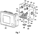
- FIG. 7 shows the auxiliary module as per FIG. 1 , having an electronics housing, having a hydraulics housing for the hydraulics unit and having a motor housing, in the assembled state in a further preferred embodiment in a perspective illustration;
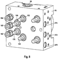
- FIG. 8 shows the hydraulics housing of the auxiliary module as per FIG. 7 in a perspective illustration
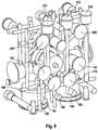
- FIG. 9 is a perspective illustration of the auxiliary module as per FIG. 7 , with the housing omitted.
- FIG. 10 is a further perspective illustration of the auxiliary module, with the housing omitted.
- FIG. 1 illustrates a preferred exemplary embodiment of a brake assembly 1 according to an aspect of the invention.
- the brake assembly 1 comprises a master brake cylinder 2 , which is actuatable by means of an actuating or brake pedal 1 a , a simulation device 3 which interacts with the brake master cylinder 2 , a pressure medium reservoir tank 4 which is assigned to the master brake cylinder 2 and which is at atmospheric pressure, an electrically controllable pressure provision device 5 , which is formed by a cylinder-piston arrangement with a hydraulic pressure space 37 , the piston 36 of which is displaceable by an electromechanical actuator comprising an electric motor and a rotation/translation mechanism, an electrically controllable pressure modulation device for setting wheel-specific brake pressures, and an electronic open-loop and closed-loop control unit 12 .
- the pressure modulation device (not designated specifically) comprises, for each hydraulically actuable wheel brake 8 , 9 , 10 , 11 and for each actuatable wheel brake 8 , 9 , 10 , 11 of a motor vehicle (not illustrated), an inlet valve 6 a - 6 d and an outlet valve 7 a - 7 d , which are hydraulically interconnected in pairs by central ports and are connected to the wheel brakes 8 , 9 , 10 , 11 .
- the inlet ports of the inlet valves 6 a - 6 d are supplied, via brake circuit supply lines 13 a , 13 b , with pressures which, in a “brake-by-wire” operating mode, are derived from a system pressure present in a system pressure line 38 which is connected to the pressure space 37 of the pressure provision device 5 .
- the brakes 8 , 9 are hydraulically connected to a first brake circuit 27
- the brakes 10 , 11 are hydraulically connected to a second brake circuit 33 .
- a check valve 50 a - 50 d which opens in the direction of the brake circuit supply lines 13 a , 13 b is connected in parallel with each of the inlet valves 6 a - 6 d .
- the brake circuit supply lines 13 a , 13 b are supplied, via hydraulic lines 22 a , 22 b , with the pressures of the pressure spaces 17 , 18 of the master brake cylinder 2 .
- the outlet ports of the outlet valves 7 a - 7 d are connected to the pressure medium reservoir tank 4 via a return line 14 b.
- the master brake cylinder 2 has, in a housing 21 , two pistons 15 , 16 which are arranged in series and which delimit the hydraulic pressure spaces 17 , 18 .
- the pressure spaces 17 , 18 are connected to the pressure medium reservoir tank 4 via radial bores formed in the pistons 15 , 16 and corresponding pressure equalization lines 41 a , 41 b , wherein the connections can be shut off by a relative movement of the pistons 15 , 16 in the housing 21 .
- the pressure spaces 17 , 18 are connected to the abovementioned brake circuit supply lines 13 a , 13 b by means of the hydraulic lines 22 a , 22 b.
- a valve 28 which is open when electrically deenergized is contained in the pressure equalization line 41 a .
- the pressure spaces 17 , 18 contain restoring springs (not designated specifically), which position the pistons 15 , 16 in an initial position when the master brake cylinder 2 is not actuated.
- a piston rod 24 couples the pivoting movement of the brake pedal 1 a resulting from a pedal actuation to the translational movement of the first master brake cylinder piston 15 , the actuation travel of which is detected by a travel sensor 25 , which is preferably of redundant design. In this way, the corresponding piston travel signal is a measure of the brake pedal actuation angle. It represents a braking demand of the vehicle driver.
- a respective isolating valve 23 a , 23 b Arranged in the line sections 22 a , 22 b connected to the pressure spaces 17 , 18 is a respective isolating valve 23 a , 23 b , which is designed as an electrically actuable 2/2-way valve which is preferably open when electrically deenergized.
- the hydraulic connection between the pressure spaces 17 , 18 of the master brake cylinder and the brake circuit supply lines 13 a , 13 b can be shut off.
- a pressure sensor 20 connected to the line section 22 b detects the pressure built up in the pressure space 18 as a result of a displacement of the second piston 16 .
- the simulation device 3 is hydraulically couplable to the master brake cylinder 2 and, in the example, is composed substantially of a simulator chamber 29 , a simulator spring chamber 30 and a simulator piston 31 which separates the two chambers 29 , 30 from one another.
- the simulator piston 31 is supported on the housing 21 by an elastic element (for example a spring), which is arranged in the simulator spring chamber 30 and which is advantageously preloaded.
- the simulator chamber 29 is connectable to the first pressure space 17 of the master brake cylinder 2 by means of an electrically actuatable simulator valve 32 . When a pedal force is input and simulator valve 32 is open, pressure medium flows from the master brake cylinder pressure space 17 into the simulator chamber 29 .
- a check valve 34 arranged hydraulically antiparallel with respect to the simulator valve 32 allows the pressure medium to flow back from the simulator chamber 29 to the master brake cylinder pressure space 17 largely unhindered, irrespective of the switching state of the simulator valve 32 .
- Other embodiments and connections of the simulation device to the master brake cylinder 2 are conceivable.
- the electrically controllable pressure provision device 5 is designed as a hydraulic cylinder-piston arrangement or a single-circuit electrohydraulic actuator, whose pressure piston 36 , which delimits the pressure space 37 , is actuatable by a schematically indicated electric motor 35 via a likewise schematically illustrated rotation/translation mechanism.
- a merely schematically indicated rotor position sensor which serves to detect the rotor position of the electric motor 35 is denoted by the reference designation 44 .
- Use may additionally also be made of a temperature sensor for sensing the temperature of the motor winding.
- the actuator pressure generated by the effect of the force of the piston 36 on the pressure medium enclosed in the pressure space 37 is fed into the system pressure line 38 and detected by means of a pressure sensor 19 , which is preferably of redundant design.
- a pressure sensor 19 which is preferably of redundant design.
- the pressure medium that has previously been displaced out of the pressure space 37 into the wheel brakes 8 , 9 , 10 , 11 flows back into the pressure space 37 over the same route.
- the pressure medium component discharged via the outlet valves 7 a - 7 d flows into the pressure medium reservoir tank 4 and is thus initially no longer available to the pressure provision device 5 for the actuation of the wheel brakes 8 , 9 , 10 , 11 .
- Additional pressure medium can be drawn into the pressure space 37 , through a replenishment line 58 , by means of a retraction of the piston 36 while the activation valves 26 a , 26 b are closed.
- the brake assembly 1 is hydraulically connected to an auxiliary module 70 which can perform braking actions in the event of failure of the pressure build-up capability of the brake assembly 1 . In this way, the time period until the driver can take over the braking of the vehicle can be bridged.
- the brake assembly 1 and auxiliary module 70 form a system or brake assembly system 72 .
- the auxiliary module 70 has a hydraulics unit 80 arranged in a housing or hydraulics housing 76 .
- a pressure provision device 86 comprises an electric motor 92 by means of which, if required, two pumps 96 , 98 can be operated.
- the pump 96 is connected at the pressure side via a hydraulic line or wheel brake feed line 102 to the wheel brake 8 .
- the pump 98 is connected at the pressure side via a line or wheel brake feed line 108 to the wheel brake 10 .
- the auxiliary module 70 is designed to be able to reliably take over the braking function when required.
- two reservoirs 120 , 130 for brake fluid are provided, which are integrated in the hydraulics unit 80 and which are arranged in the hydraulics housing 76 .
- the brake fluid reservoir 120 is hydraulically connected to the suction side of the pump 96 via a hydraulic line 136 , into which there is connected a reservoir valve 142 which is closed when electrically deenergized.
- the reservoir 130 is hydraulically connected, at the suction side, to the pump 98 via a hydraulic line 148 , into which there is connected a reservoir valve 152 which is closed when electrically deenergized.
- a pressure sensor 160 which is preferably of redundant design measures the pressure in the line 102 .
- a pressure sensor 162 of preferably redundant design measures the pressure in the line 108 .
- An open-loop and closed-loop control unit 182 is connected at the signal input side to the pressure sensors 160 , 162 .
- a hydraulic return line 170 which hydraulically connects line 102 to the reservoir 120 , wherein a return valve 176 which is closed when electrically deenergized is connected into the return line.
- a hydraulic return line 180 From the line 108 , there branches off a hydraulic return line 180 , into which a return valve 186 which is closed when electrically deenergized is connected.
- a common hydraulic equalization line 190 which is illustrated by dashed lines in FIG. 1 and which is led partially through the housing 21 of the brake assembly 1 , connects the two reservoirs 120 , 130 to the brake medium reservoir tank 4 .
- an equalization line 192 which is led outside the housing 21 , is connected to the brake medium reservoir tank 4 at a separate brake medium tank port 196 situated outside the housing 21 .
- the equalization line 190 , 192 is preferably formed at least partially as a steel line.
- the wheel brake 9 which in the present case corresponds to the right-hand rear-wheel brake, is connected to the pressure provision device via a brake line 202 .
- the wheel brake 11 which corresponds to the left-hand rear-wheel brake, is connected via a brake line 206 to the pressure provision device 5 .
- the wheel brake 8 which corresponds to the left-hand front-wheel brake, is connected by means of a brake line 200 to the pressure provision device 5 .
- the wheel brake 10 which corresponds to the right-hand front-wheel brake, is connected via a brake line 204 to the pressure provision device.
- the auxiliary module 70 is connected hydraulically into the brake lines 200 , 204 such that a section of said brake lines, which is also referred to here as wheel brake feed line 102 , 108 , runs in the auxiliary module 70 .
- a section of said brake lines which is also referred to here as wheel brake feed line 102 , 108 , runs in the auxiliary module 70 .
- the brake line 200 runs, in a line section 210 , within the auxiliary module 70 .
- the line section 210 connects a section 216 , which runs within the brake assembly 1 , to the hydraulic line 102 .
- An isolating valve 220 which is open when electrically deenergized is connected into the line section 210 , in parallel with which isolating valve there is connected a check valve 226 which, when the isolating valve 220 is shut off, prevents the return flow of brake fluid out of the wheel brake 8 .
- a pressure sensor 194 measures the pressure in the brake line 200 .
- the signal of the pressure sensor serves preferably for detecting the driver braking demand in a fall-back level, in which the brake pressure setting is performed by the auxiliary module.
- the brake line 204 runs, in a line section 234 , within the auxiliary module 70 .
- the line section 234 hydraulically connects a section 238 , which runs within the brake assembly 1 , to the hydraulic line 108 .
- An isolating valve 240 which is open when electrically deenergized is connected into the line section 234 , in parallel with which isolating valve there is connected a check valve 246 which, when the isolating valve 240 is shut off, prevents the return flow of brake fluid out of the wheel brake 10 .
- the auxiliary module 70 can build up pressure in the two front-wheel brakes 8 , 10 .
- the two isolating valves 220 , 240 are switched into their isolating position, such that the wheel brakes 8 , 10 are hydraulically isolated from the pressure provision device 5 and from the master brake cylinder 2 .
- the open-loop and closed-loop control unit 182 activates the electric motor 92 , which activates the pumps 96 , 98 .
- the respective pump 96 , 98 then draws in brake fluid from the respective reservoir 120 , 130 and conveys said brake fluid through the corresponding wheel brake feed line 102 , 108 into the wheel brake 8 , 10 .
- the return valves 176 , 186 are switched into their isolating position for as long as the same brake pressure is to be built up in both wheel brakes 8 , 10 .
- one or both return valves 176 , 186 is/are, if required, opened and function(s) as outlet valve(s), through which brake fluid can flow into the respective reservoir 120 , 130 .
- the auxiliary module 70 preferably remains active when the driver, in a hydraulic fall-back level, builds up brake force by muscle force by actuating the brake pedal 1 a , and it thus remains possible for a brake force boosting function to be provided. It is also thus possible (at least for the front axle) to realize an ABS function and, through targeted pressure reduction, also an EBD function for the rear axle.
- an EPB electronic parking brake
- This activation is withdrawn when the driver performs a braking input, in order to avoid overbraking (locking up) of the rear axle.
- FIG. 2 is a perspective illustration of the auxiliary module 70 as per FIG. 1 .
- the hydraulics housing 76 of the hydraulics unit 80 is, in effect, sandwiched between the motor 92 , which is arranged in a motor housing 94 , and an electronics housing 250 , in which the open-loop and closed-loop control unit 182 is arranged and which has an electrical connector plug 252 .
- the motor 92 is arranged on the opposite side of the housing 76 in relation to the electronics housing 250 .
- One of the two pumps 96 is visible on the left-hand side of the housing 76 in the figure, and the other pump 98 is arranged on the opposite side.
- a valve receptacle 256 is also illustrated.
- a port 270 serves for the connection of the auxiliary module to a brake medium reservoir tank of a brake assembly, in particular to the brake medium reservoir tank 4 of the brake assembly 1 . Also visible are hydraulic outlets 272 , 274 to wheel brakes (wheel brakes 8 , 10 in FIG. 1 ) and a fastening bolt 262 for the ECU. For the connection to the brake assembly 1 (for example to the sections 216 and 238 in FIG. 1 ), hydraulic inlets 272 a , 274 a are provided.
- FIG. 2 Also visible in FIG. 2 are two pipes 280 , 282 and two closure covers 286 , 288 .
- the pipe 280 is arranged in the reservoir 120 which is closed off by the closure cover 286 .
- the pipe 282 is arranged in the reservoir 148 which is closed off by the closure cover 288 .
- FIG. 3 shows that side of the housing 76 which faces toward the electronics housing 250 .
- the isolating valves 220 , 240 which are open when electrically deenergized, are arranged in a first row.
- a two-row group of four of the valves 142 , 152 , 176 , 186 which are closed when electrically deenergized, wherein, in each case, the two reservoir valves 142 , 152 are arranged in one row, and the two return valves 178 , 186 are arranged in a row of two.
- the three pressure sensors 160 , 162 , 194 which are arranged in one row.
- FIG. 4 shows a section, from a side elevation, through the reservoir 120 closed off by means of the closure cover 286 , and through the pipe 280 which is arranged in the reservoir 120 and which prevents the pump 96 from drawing in air.
- FIG. 5 is an illustration of the components arranged in the housing 76 , wherein the housing is not visible in this illustration. As a result, the valve and sensor positions of the auxiliary module 70 can be clearly seen.
- FIG. 6 shows a view, from the motor side, of the auxiliary module 70 , with the housing 76 not being visible.
- a bore 300 for a motor plug which serves for the electrical connection of the motor 90 to the open-loop and closed-loop control unit 182 or ECU.
- Bores 306 , 310 , 312 receive fastening bolts for fastening bolts of the ECU.
- a motor bore 320 contains the A bearing of the motor 90 or the eccentric shaft end of the motor and thus forms an eccentric bearing.
- a reservoir 340 for leakage fluid from the pumps 96 , 98 is also visible in the figure.
- FIG. 7 An auxiliary module 70 in a further preferred embodiment is illustrated in FIG. 7 . This differs from the embodiment of the auxiliary module 70 illustrated in FIG. 3 by the arrangement of the valves 152 , 142 , 186 , 176 , which have now been relocated closer to the pressure sensors 194 , 160 , 162 .
- FIGS. 8, 9 and 10 show this embodiment of the auxiliary module again in further perspective illustrations.
Landscapes
- Engineering & Computer Science (AREA)
- Physics & Mathematics (AREA)
- Transportation (AREA)
- Mechanical Engineering (AREA)
- Fluid Mechanics (AREA)
- Electromagnetism (AREA)
- Regulating Braking Force (AREA)
- Valves And Accessory Devices For Braking Systems (AREA)
- Braking Systems And Boosters (AREA)
Applications Claiming Priority (3)
| Application Number | Priority Date | Filing Date | Title |
|---|---|---|---|
| DE102016203119.8A DE102016203119A1 (de) | 2016-02-26 | 2016-02-26 | Zusatzmodul für eine elektrohydraulische Bremsanlage und Bremsanlagensystem |
| DE102016203119.8 | 2016-02-26 | ||
| PCT/EP2017/051171 WO2017144201A1 (de) | 2016-02-26 | 2017-01-20 | Zusatzmodul für eine elektrohydraulische bremsanlage und bremsanlagensystem mit einem derartigen zusatzmodul |
Publications (2)
| Publication Number | Publication Date |
|---|---|
| US20190016321A1 US20190016321A1 (en) | 2019-01-17 |
| US11001245B2 true US11001245B2 (en) | 2021-05-11 |
Family
ID=57851085
Family Applications (1)
| Application Number | Title | Priority Date | Filing Date |
|---|---|---|---|
| US16/070,340 Active 2037-04-21 US11001245B2 (en) | 2016-02-26 | 2017-01-20 | Add-on module for an electrohydraulic brake assembly, and brake assembly system comprising an add-on module of said type |
Country Status (7)
| Country | Link |
|---|---|
| US (1) | US11001245B2 (de) |
| EP (1) | EP3419876B1 (de) |
| JP (1) | JP6633769B2 (de) |
| KR (1) | KR102102070B1 (de) |
| CN (1) | CN108698577B (de) |
| DE (1) | DE102016203119A1 (de) |
| WO (1) | WO2017144201A1 (de) |
Cited By (6)
| Publication number | Priority date | Publication date | Assignee | Title |
|---|---|---|---|---|
| US11358577B2 (en) | 2019-01-03 | 2022-06-14 | Hyundai Mobis Co., Ltd. | Hydraulic block of electronic braking device for vehicle and electronic braking device for vehicle having the same |
| US20220234559A1 (en) * | 2021-01-27 | 2022-07-28 | Advics North America, Inc. | Series-connected brake actuators and automatic brake hold method employing same |
| US11485336B2 (en) * | 2019-10-29 | 2022-11-01 | Hyundai Mobis Co., Ltd. | Hydraulic block for redundancy of electronic braking device for vehicle |
| US20230012180A1 (en) * | 2021-07-12 | 2023-01-12 | Hyundai Mobis Co., Ltd. | Electric hydraulic brake |
| US20240026908A1 (en) * | 2022-07-25 | 2024-01-25 | Deere & Company | Arrangement for operating a hydraulic consumer |
| US20240288008A1 (en) * | 2023-02-27 | 2024-08-29 | Deere & Company | Hydraulic assembly for supplying an attachment with hydraulic power |
Families Citing this family (31)
| Publication number | Priority date | Publication date | Assignee | Title |
|---|---|---|---|---|
| DE102017216118A1 (de) * | 2016-10-11 | 2018-04-12 | Continental Teves Ag & Co. Ohg | Verfahren zum Betrieb einer elektrohydraulischen Bremsanlage und Bremsanlage |
| DE102017113563A1 (de) * | 2017-06-20 | 2018-12-20 | Ipgate Ag | Bremssystem |
| DE102017213858A1 (de) * | 2017-08-09 | 2019-02-14 | Continental Teves Ag & Co. Ohg | Bremsanlage für Kraftfahrzeuge |
| DE102017220308A1 (de) * | 2017-11-15 | 2019-05-16 | Continental Teves Ag & Co. Ohg | Verfahren zum Überprüfen der Funktionalität eines Bremssystems und Bremssystem |
| DE102018002990B4 (de) * | 2018-04-12 | 2025-10-09 | Zf Active Safety Gmbh | Hydraulische Kraftfahrzeug-Bremsanlage und Verfahren zum Betreiben derselben |
| WO2019215030A1 (de) | 2018-05-09 | 2019-11-14 | Ipgate Ag | Bremssystem |
| CN110466489A (zh) * | 2018-05-09 | 2019-11-19 | 罗伯特·博世有限公司 | 用于自主行驶的地面车辆的电液式助力-车辆制动系统 |
| EP4653272A2 (de) * | 2018-12-20 | 2025-11-26 | Ipgate Ag | Redundantes bremssystem mit einer druckversorgung für e- fahrzeuge und fahrzeuge mit autonomem fahren der stufe 3 (had) bis stufe 4 (fad) |
| EP4501721A3 (de) | 2018-12-20 | 2025-02-19 | Ipgate Ag | Redundantes bremssystem mit 2 druckversorgungen für elektrofahrzeug und fahrzueuge mit autonomem fahren der stufe 3 (had) bis stufe 5 (ad) |
| DE102019203308A1 (de) * | 2019-03-12 | 2020-09-17 | Continental Teves Ag & Co. Ohg | Hydraulikaggregat |
| WO2020210319A1 (en) * | 2019-04-09 | 2020-10-15 | Continental Automotive Systems, Inc. | Braking system for heavy duty vehicles and related methods |
| CN110525410A (zh) * | 2019-08-23 | 2019-12-03 | 芜湖伯特利汽车安全系统股份有限公司 | 一种车辆冗余行车制动辅助系统 |
| KR102276119B1 (ko) * | 2019-10-08 | 2021-07-12 | 현대모비스 주식회사 | 전자식 유압 브레이크 장치 |
| DE102020200570A1 (de) * | 2020-01-18 | 2021-07-22 | Robert Bosch Gesellschaft mit beschränkter Haftung | Rückschlagventil für eine hydraulische Fremdkraft-Fahrzeugbremsanlage und hydraulische Fremdkraft-Fahrzeugbremsanlage |
| KR102727836B1 (ko) * | 2020-03-20 | 2024-11-07 | 현대모비스 주식회사 | 4 휠 제어가 가능한 전자 유압식 브레이크 장치 |
| USD965637S1 (en) * | 2020-04-10 | 2022-10-04 | Dallas Fabian | Air manifold for a truck |
| KR102773544B1 (ko) * | 2020-05-11 | 2025-02-25 | 현대모비스 주식회사 | 차량용 제동장치 및 그 제어방법 |
| KR102845371B1 (ko) * | 2020-06-22 | 2025-08-11 | 현대모비스 주식회사 | 차량용 제동장치 및 그 제동방법 |
| US11981303B2 (en) * | 2020-08-21 | 2024-05-14 | Robert Bosch Gmbh | Vehicle braking system and method of operating the same |
| KR102484451B1 (ko) | 2021-01-22 | 2023-01-02 | 현대모비스 주식회사 | 전자식 유압 브레이크 장치 및 제어방법 |
| US11919500B2 (en) | 2021-03-01 | 2024-03-05 | ZF Active Safety US Inc. | Apparatus and method for control of a hydraulic brake system |
| DE102021204255A1 (de) * | 2021-04-28 | 2022-11-03 | Robert Bosch Gesellschaft mit beschränkter Haftung | Hydraulikblock für ein Betriebsbremsaggregat einer hydraulischen Fremdkraftbremsanlage |
| KR20230003947A (ko) * | 2021-06-30 | 2023-01-06 | 현대모비스 주식회사 | 차량용 제동장치 |
| US12503092B2 (en) * | 2021-12-02 | 2025-12-23 | Bwi (Shanghai) Co., Ltd. | Electronic stability control-based brake actuation with redundancy |
| CN116331176B (zh) * | 2021-12-22 | 2025-10-21 | 比博斯特(上海)汽车电子有限公司 | 机械液压拖挂式房车制动系统 |
| DE102022203990A1 (de) | 2022-01-13 | 2023-07-13 | Continental Automotive Technologies GmbH | Hydraulische Bremsanlage für niedrige Temperaturen und Verfahren zum Betrieb einer solchen Bremsanlage |
| WO2023134830A1 (de) | 2022-01-13 | 2023-07-20 | Continental Automotive Technologies GmbH | Hydraulische bremsanlage für niedrige temperaturen und verfahren zum betrieb einer solchen bremsanlage |
| DE102022202832A1 (de) | 2022-03-23 | 2023-09-28 | Continental Automotive Technologies GmbH | Bremssystem und Verfahren zu dessen Betrieb |
| DE102022202911A1 (de) | 2022-03-24 | 2023-09-28 | Continental Automotive Technologies GmbH | Bremssystem |
| KR102658541B1 (ko) | 2022-06-13 | 2024-04-18 | 현대모비스 주식회사 | 전자식 유압 브레이크 장치 |
| KR102694061B1 (ko) | 2022-06-13 | 2024-08-09 | 현대모비스 주식회사 | 전자식 유압 브레이크 장치 |
Citations (33)
| Publication number | Priority date | Publication date | Assignee | Title |
|---|---|---|---|---|
| US5921640A (en) * | 1995-05-19 | 1999-07-13 | Lucas Industries Public, Ltd. | Electronic braking systems |
| US5924775A (en) * | 1994-12-22 | 1999-07-20 | Itt Manufacturing Enterprises, Inc. | Antiskid hydraulic braking system |
| US5997106A (en) * | 1996-10-18 | 1999-12-07 | Tokico Ltd. | Brake fluid pressure control system and method of controlling the same |
| DE10023301A1 (de) | 1999-06-08 | 2001-01-25 | Continental Teves Ag & Co Ohg | Elektronisch regelbare Bremsanlage |
| US6428121B1 (en) * | 1999-02-01 | 2002-08-06 | Continental Teves Ag & Co., Ohg | Pressure control device |
| US20040004393A1 (en) | 2002-07-04 | 2004-01-08 | Philippe Richard | Brake booster |
| JP2004338565A (ja) | 2003-05-15 | 2004-12-02 | Continental Teves Ag & Co Ohg | 車両用ブレーキ液圧制御アクチュエータ |
| CN101039829A (zh) | 2004-10-15 | 2007-09-19 | 大陆-特韦斯贸易合伙股份公司及两合公司 | 用于机动车辆的制动设备 |
| US7517027B2 (en) * | 2005-01-17 | 2009-04-14 | Honda Motor Co., Ltd. | Hydraulic brake device |
| US20100219679A1 (en) * | 2007-10-11 | 2010-09-02 | Honda Motor Co., Ltd. | Brake apparatus |
| US20100282549A1 (en) * | 2006-08-10 | 2010-11-11 | Continental Teves Ag & Co. Ohg | Externally Controllable Electrohydraulic Vehicle Brake System |
| JP2012106644A (ja) | 2010-11-17 | 2012-06-07 | Honda Motor Co Ltd | 電動ブレーキアクチュエータの車体取付構造 |
| JP2012111334A (ja) | 2010-11-24 | 2012-06-14 | Nissin Kogyo Co Ltd | 液圧制御装置 |
| DE102012205862A1 (de) | 2011-04-19 | 2012-10-25 | Continental Teves Ag & Co. Ohg | Bremsanlage für Kraftfahrzeuge sowie Verfahren zum Betrieb einer Bremsanlage |
| WO2012150120A1 (de) | 2011-05-05 | 2012-11-08 | Continental Teves Ag & Co. Ohg | Bremsanlage für kraftfahrzeuge sowie verfahren zum betrieb der bremsanlage |
| DE102013204778A1 (de) | 2012-03-22 | 2013-09-26 | Continental Teves Ag & Co. Ohg | Verfahren zur haptischen Information des Fahrers eines Kraftfahrzeugs |
| JP2014019243A (ja) | 2012-07-17 | 2014-02-03 | Honda Motor Co Ltd | 制動力発生装置 |
| KR20140023369A (ko) | 2011-04-19 | 2014-02-26 | 콘티넨탈 테베스 아게 운트 코. 오하게 | 모터 차량용 브레이크 시스템 및 브레이크 시스템의 동작 방법 |
| WO2014048600A1 (de) | 2012-09-28 | 2014-04-03 | Continental Teves Ag & Co. Ohg | Kombinierte bremsanlage für fahrzeuge sowie verfahren zu deren betrieb |
| US8857922B2 (en) * | 2010-06-22 | 2014-10-14 | Continental Teves Ag & Co. Ohg | Hydraulic vehicle brake system |
| JP2014213628A (ja) | 2013-04-23 | 2014-11-17 | 本田技研工業株式会社 | 車両の制動システム |
| JP2014227092A (ja) | 2013-05-23 | 2014-12-08 | 本田技研工業株式会社 | 車両制御装置 |
| US20150151726A1 (en) | 2013-12-04 | 2015-06-04 | Continental Automotive Systems, Inc. | Hydraulic and electronic braking system for autonomous braking |
| WO2015106892A1 (de) | 2014-01-15 | 2015-07-23 | Continental Teves Ag & Co. Ohg | Bremsensteuervorrichtung sowie bremsanlage für fahrzeuge |
| US20150239444A1 (en) | 2014-02-26 | 2015-08-27 | Denso Corporation | Brake fluid pressure control actuator |
| WO2015139983A1 (de) | 2014-03-18 | 2015-09-24 | Continental Teves Ag & Co. Ohg | Elektrohydraulisches aggregat und bremsanlage |
| DE102014212537A1 (de) | 2014-06-30 | 2015-12-31 | Continental Teves Ag & Co. Ohg | Bremsanlage für ein Kraftfahrzeug |
| DE102016201047A1 (de) | 2015-01-29 | 2016-08-04 | Continental Teves Ag & Co. Ohg | Bremsanlage für Kraftfahrzeuge |
| US20170096130A1 (en) * | 2014-06-30 | 2017-04-06 | Continental Teves Ag & Co. Ohg | Assembly for a hydraulic motor-vehicle brake system and brake system having such an assembly |
| US20180065609A1 (en) * | 2015-03-20 | 2018-03-08 | Ipgate Ag | Actuating apparatus for a motor vehicle brake |
| US20180265060A1 (en) * | 2015-09-01 | 2018-09-20 | Hitachi Automotive Systems, Ltd. | Brake Device and Brake System |
| US10137877B2 (en) * | 2013-02-27 | 2018-11-27 | Continental Teves Ag & Co. Ohg | Brake system for motor vehicles |
| US10391994B2 (en) * | 2015-03-05 | 2019-08-27 | Continental Teves Ag & Co. Ohg | Brake system for motor vehicles |
-
2016
- 2016-02-26 DE DE102016203119.8A patent/DE102016203119A1/de not_active Withdrawn
-
2017
- 2017-01-20 KR KR1020187023273A patent/KR102102070B1/ko active Active
- 2017-01-20 WO PCT/EP2017/051171 patent/WO2017144201A1/de not_active Ceased
- 2017-01-20 US US16/070,340 patent/US11001245B2/en active Active
- 2017-01-20 JP JP2018543334A patent/JP6633769B2/ja active Active
- 2017-01-20 CN CN201780010250.5A patent/CN108698577B/zh active Active
- 2017-01-20 EP EP17700843.0A patent/EP3419876B1/de active Active
Patent Citations (47)
| Publication number | Priority date | Publication date | Assignee | Title |
|---|---|---|---|---|
| US5924775A (en) * | 1994-12-22 | 1999-07-20 | Itt Manufacturing Enterprises, Inc. | Antiskid hydraulic braking system |
| US5921640A (en) * | 1995-05-19 | 1999-07-13 | Lucas Industries Public, Ltd. | Electronic braking systems |
| US5997106A (en) * | 1996-10-18 | 1999-12-07 | Tokico Ltd. | Brake fluid pressure control system and method of controlling the same |
| US6428121B1 (en) * | 1999-02-01 | 2002-08-06 | Continental Teves Ag & Co., Ohg | Pressure control device |
| DE10023301A1 (de) | 1999-06-08 | 2001-01-25 | Continental Teves Ag & Co Ohg | Elektronisch regelbare Bremsanlage |
| US20040004393A1 (en) | 2002-07-04 | 2004-01-08 | Philippe Richard | Brake booster |
| JP2004338565A (ja) | 2003-05-15 | 2004-12-02 | Continental Teves Ag & Co Ohg | 車両用ブレーキ液圧制御アクチュエータ |
| US7004552B2 (en) | 2003-05-15 | 2006-02-28 | Continental Teves Ag & Co. | Brake hydraulic control actuator for vehicles |
| CN101039829A (zh) | 2004-10-15 | 2007-09-19 | 大陆-特韦斯贸易合伙股份公司及两合公司 | 用于机动车辆的制动设备 |
| US7517027B2 (en) * | 2005-01-17 | 2009-04-14 | Honda Motor Co., Ltd. | Hydraulic brake device |
| US20100282549A1 (en) * | 2006-08-10 | 2010-11-11 | Continental Teves Ag & Co. Ohg | Externally Controllable Electrohydraulic Vehicle Brake System |
| US20100219679A1 (en) * | 2007-10-11 | 2010-09-02 | Honda Motor Co., Ltd. | Brake apparatus |
| US8857922B2 (en) * | 2010-06-22 | 2014-10-14 | Continental Teves Ag & Co. Ohg | Hydraulic vehicle brake system |
| JP2012106644A (ja) | 2010-11-17 | 2012-06-07 | Honda Motor Co Ltd | 電動ブレーキアクチュエータの車体取付構造 |
| JP2012111334A (ja) | 2010-11-24 | 2012-06-14 | Nissin Kogyo Co Ltd | 液圧制御装置 |
| DE102012205862A1 (de) | 2011-04-19 | 2012-10-25 | Continental Teves Ag & Co. Ohg | Bremsanlage für Kraftfahrzeuge sowie Verfahren zum Betrieb einer Bremsanlage |
| US9145119B2 (en) | 2011-04-19 | 2015-09-29 | Continental Teves Ag & Co. Ohg | Brake system for motor vehicles and method for operating a brake system |
| US20140203626A1 (en) * | 2011-04-19 | 2014-07-24 | Harald Biller | Brake System for Motor Vehicles and Method for Operating a Brake System |
| US20140110997A1 (en) * | 2011-04-19 | 2014-04-24 | Continential Teves Ag & Co. Ohg | Brake System for Motor Vehicles and Method for Operating the Brake System |
| KR20140023369A (ko) | 2011-04-19 | 2014-02-26 | 콘티넨탈 테베스 아게 운트 코. 오하게 | 모터 차량용 브레이크 시스템 및 브레이크 시스템의 동작 방법 |
| US20140152085A1 (en) | 2011-05-05 | 2014-06-05 | Continental Teves Ag & Co. Ohg | Brake System for Motor Vehicles. and Method for Operating the Brake System |
| WO2012150120A1 (de) | 2011-05-05 | 2012-11-08 | Continental Teves Ag & Co. Ohg | Bremsanlage für kraftfahrzeuge sowie verfahren zum betrieb der bremsanlage |
| US9308905B2 (en) * | 2011-05-05 | 2016-04-12 | Continental Teves Ag & Co. Ohg | Brake system for motor vehicles and method for operating the brake system |
| DE102012205962A1 (de) | 2011-05-05 | 2012-11-08 | Continental Teves Ag & Co. Ohg | Bremsanlage für Kraftfahrzeuge sowie Verfahren zum Betrieb einer Bremsanlage |
| DE102013204778A1 (de) | 2012-03-22 | 2013-09-26 | Continental Teves Ag & Co. Ohg | Verfahren zur haptischen Information des Fahrers eines Kraftfahrzeugs |
| US9415758B2 (en) | 2012-03-22 | 2016-08-16 | Continental Teves Ag & Co. Ohg | Method for providing haptic information to the driver of a motor vehicle |
| US9109613B2 (en) | 2012-07-17 | 2015-08-18 | Honda Motor Co., Ltd. | Braking-force generator |
| JP2014019243A (ja) | 2012-07-17 | 2014-02-03 | Honda Motor Co Ltd | 制動力発生装置 |
| WO2014048600A1 (de) | 2012-09-28 | 2014-04-03 | Continental Teves Ag & Co. Ohg | Kombinierte bremsanlage für fahrzeuge sowie verfahren zu deren betrieb |
| US10137877B2 (en) * | 2013-02-27 | 2018-11-27 | Continental Teves Ag & Co. Ohg | Brake system for motor vehicles |
| JP2014213628A (ja) | 2013-04-23 | 2014-11-17 | 本田技研工業株式会社 | 車両の制動システム |
| US9020712B2 (en) | 2013-05-23 | 2015-04-28 | Honda Motor Co., Ltd. | Vehicle control device |
| JP2014227092A (ja) | 2013-05-23 | 2014-12-08 | 本田技研工業株式会社 | 車両制御装置 |
| US20150151726A1 (en) | 2013-12-04 | 2015-06-04 | Continental Automotive Systems, Inc. | Hydraulic and electronic braking system for autonomous braking |
| US20160339885A1 (en) | 2014-01-15 | 2016-11-24 | Continental Teves Ag & Co. Ohg | Brake control device and brake system for vehicles |
| WO2015106892A1 (de) | 2014-01-15 | 2015-07-23 | Continental Teves Ag & Co. Ohg | Bremsensteuervorrichtung sowie bremsanlage für fahrzeuge |
| JP2015160464A (ja) | 2014-02-26 | 2015-09-07 | 株式会社デンソー | ブレーキ液圧制御用アクチュエータ |
| US20150239444A1 (en) | 2014-02-26 | 2015-08-27 | Denso Corporation | Brake fluid pressure control actuator |
| WO2015139983A1 (de) | 2014-03-18 | 2015-09-24 | Continental Teves Ag & Co. Ohg | Elektrohydraulisches aggregat und bremsanlage |
| US20170232947A1 (en) | 2014-03-18 | 2017-08-17 | Continental Teves Ag & Co. Ohg | Electrohydraulic Assembly and Brake System |
| DE102014212537A1 (de) | 2014-06-30 | 2015-12-31 | Continental Teves Ag & Co. Ohg | Bremsanlage für ein Kraftfahrzeug |
| US20170096130A1 (en) * | 2014-06-30 | 2017-04-06 | Continental Teves Ag & Co. Ohg | Assembly for a hydraulic motor-vehicle brake system and brake system having such an assembly |
| US20170129468A1 (en) | 2014-06-30 | 2017-05-11 | Continental Teves Ag & Co. Ohg | Braking system for a motor vehicle |
| DE102016201047A1 (de) | 2015-01-29 | 2016-08-04 | Continental Teves Ag & Co. Ohg | Bremsanlage für Kraftfahrzeuge |
| US10391994B2 (en) * | 2015-03-05 | 2019-08-27 | Continental Teves Ag & Co. Ohg | Brake system for motor vehicles |
| US20180065609A1 (en) * | 2015-03-20 | 2018-03-08 | Ipgate Ag | Actuating apparatus for a motor vehicle brake |
| US20180265060A1 (en) * | 2015-09-01 | 2018-09-20 | Hitachi Automotive Systems, Ltd. | Brake Device and Brake System |
Non-Patent Citations (5)
| Title |
|---|
| Chinese Office Action for Chinese Application No. 201780010250.5, dated Apr. 16, 2020 with translation, 17 pages. |
| German Search Report for German Application No. 10 2016 203 119.8, dated Feb. 8, 2017, with partial translation—12 pages. |
| International Search Report and Written Opinion for International Application No. PCT/EP2017/051171, dated Mar. 27, 2017—11 pages. |
| Notice of Grounds for Rejection for Korean Application No. 10-2018-7023273, dated Jul. 11, 2019, with translation, 16 pages. |
| Notice of Reasons for Refusal for Japanese Application No. 2018-543334, dated Aug. 7, 2019, with translation, 12 pages. |
Cited By (13)
| Publication number | Priority date | Publication date | Assignee | Title |
|---|---|---|---|---|
| US11702056B2 (en) | 2019-01-03 | 2023-07-18 | Hyundai Mobis Co., Ltd. | Hydraulic block for electronic braking device and electronic braking device having the same |
| US11358577B2 (en) | 2019-01-03 | 2022-06-14 | Hyundai Mobis Co., Ltd. | Hydraulic block of electronic braking device for vehicle and electronic braking device for vehicle having the same |
| US11485336B2 (en) * | 2019-10-29 | 2022-11-01 | Hyundai Mobis Co., Ltd. | Hydraulic block for redundancy of electronic braking device for vehicle |
| US20220234559A1 (en) * | 2021-01-27 | 2022-07-28 | Advics North America, Inc. | Series-connected brake actuators and automatic brake hold method employing same |
| US12017623B2 (en) * | 2021-01-27 | 2024-06-25 | Advics Co., Ltd. | Series-connected brake actuators and automatic brake hold method employing same |
| US20230012180A1 (en) * | 2021-07-12 | 2023-01-12 | Hyundai Mobis Co., Ltd. | Electric hydraulic brake |
| EP4119405A1 (de) * | 2021-07-12 | 2023-01-18 | Hyundai Mobis Co., Ltd. | Elektrische hydraulische bremse |
| CN115610394A (zh) * | 2021-07-12 | 2023-01-17 | 现代摩比斯株式会社 | 电动液压制动器 |
| CN115610394B (zh) * | 2021-07-12 | 2025-07-22 | 现代摩比斯株式会社 | 电动液压制动器 |
| US12459476B2 (en) * | 2021-07-12 | 2025-11-04 | Hyundai Mobis Co., Ltd. | Electric hydraulic brake |
| US20240026908A1 (en) * | 2022-07-25 | 2024-01-25 | Deere & Company | Arrangement for operating a hydraulic consumer |
| US12313091B2 (en) * | 2022-07-25 | 2025-05-27 | Deere & Company | Arrangement for operating a hydraulic consumer |
| US20240288008A1 (en) * | 2023-02-27 | 2024-08-29 | Deere & Company | Hydraulic assembly for supplying an attachment with hydraulic power |
Also Published As
| Publication number | Publication date |
|---|---|
| JP6633769B2 (ja) | 2020-01-22 |
| KR20180101525A (ko) | 2018-09-12 |
| JP2019505438A (ja) | 2019-02-28 |
| EP3419876A1 (de) | 2019-01-02 |
| CN108698577A (zh) | 2018-10-23 |
| EP3419876B1 (de) | 2020-01-08 |
| DE102016203119A1 (de) | 2017-08-31 |
| US20190016321A1 (en) | 2019-01-17 |
| CN108698577B (zh) | 2021-02-05 |
| WO2017144201A1 (de) | 2017-08-31 |
| KR102102070B1 (ko) | 2020-05-29 |
Similar Documents
| Publication | Publication Date | Title |
|---|---|---|
| US11001245B2 (en) | Add-on module for an electrohydraulic brake assembly, and brake assembly system comprising an add-on module of said type | |
| US10752228B2 (en) | Method for operating an electro hydraulic brake system, and brake system | |
| US11999326B2 (en) | Braking system with two pressure sources, and method for operating a braking system with two pressure sources | |
| US11648924B2 (en) | Brake system with two pressure sources, and two methods for operating a brake system | |
| US20200139949A1 (en) | Braking system | |
| US10703347B2 (en) | Method for operating a brake system of a motor vehicle, and brake system | |
| JP6774572B2 (ja) | 自動車用制動設備及び制動設備の動作方法 | |
| US10358119B2 (en) | Braking system for a motor vehicle | |
| US9205821B2 (en) | Brake system for motor vehicles | |
| US20250042381A1 (en) | Brake system for a motor vehicle | |
| US9834188B2 (en) | Brake system for motor vehicles | |
| KR102328466B1 (ko) | 자동차용 제동 시스템 | |
| US10137877B2 (en) | Brake system for motor vehicles | |
| US9868426B2 (en) | Pressure provision device and brake system | |
| US20160200307A1 (en) | Brake System for Motor Vehicles | |
| US10800388B2 (en) | Method for operating a brake system for motor vehicles, and brake system | |
| CN105026232A (zh) | 制动操作单元 | |
| US20250145135A1 (en) | Brake system for a motor vehicle and assembly for a brake system | |
| US20230192056A1 (en) | Hydraulic motor vehicle brake system |
Legal Events
| Date | Code | Title | Description |
|---|---|---|---|
| FEPP | Fee payment procedure |
Free format text: ENTITY STATUS SET TO UNDISCOUNTED (ORIGINAL EVENT CODE: BIG.); ENTITY STATUS OF PATENT OWNER: LARGE ENTITY |
|
| AS | Assignment |
Owner name: CONTINENTAL TEVES AG & CO. OHG, GERMANY Free format text: CORRECTIVE ASSIGNMENT TO CORRECT THE APPLICATION NUMBER PREVIOUSLY RECORDED ON REEL 046896 FRAME 0072. ASSIGNOR(S) HEREBY CONFIRMS THE CORRECT APPLICATION NUMBER IS 16/070,340;ASSIGNOR:DINKEL, DIETER;REEL/FRAME:047240/0480 Effective date: 20180622 |
|
| STPP | Information on status: patent application and granting procedure in general |
Free format text: APPLICATION DISPATCHED FROM PREEXAM, NOT YET DOCKETED |
|
| STPP | Information on status: patent application and granting procedure in general |
Free format text: DOCKETED NEW CASE - READY FOR EXAMINATION |
|
| STPP | Information on status: patent application and granting procedure in general |
Free format text: NON FINAL ACTION MAILED |
|
| STPP | Information on status: patent application and granting procedure in general |
Free format text: FINAL REJECTION MAILED |
|
| STPP | Information on status: patent application and granting procedure in general |
Free format text: RESPONSE AFTER FINAL ACTION FORWARDED TO EXAMINER |
|
| STPP | Information on status: patent application and granting procedure in general |
Free format text: DOCKETED NEW CASE - READY FOR EXAMINATION |
|
| STPP | Information on status: patent application and granting procedure in general |
Free format text: NOTICE OF ALLOWANCE MAILED -- APPLICATION RECEIVED IN OFFICE OF PUBLICATIONS |
|
| STPP | Information on status: patent application and granting procedure in general |
Free format text: PUBLICATIONS -- ISSUE FEE PAYMENT RECEIVED |
|
| STPP | Information on status: patent application and granting procedure in general |
Free format text: PUBLICATIONS -- ISSUE FEE PAYMENT VERIFIED |
|
| STCF | Information on status: patent grant |
Free format text: PATENTED CASE |
|
| AS | Assignment |
Owner name: CONTINENTAL AUTOMOTIVE TECHNOLOGIES GMBH, GERMANY Free format text: MERGER AND CHANGE OF NAME;ASSIGNORS:CONTINENTAL TEVES AG & CO. OHG;CONTINENTAL AUTOMOTIVE TECHNOLOGIES GMBH;REEL/FRAME:068794/0001 Effective date: 20220714 |
|
| MAFP | Maintenance fee payment |
Free format text: PAYMENT OF MAINTENANCE FEE, 4TH YEAR, LARGE ENTITY (ORIGINAL EVENT CODE: M1551); ENTITY STATUS OF PATENT OWNER: LARGE ENTITY Year of fee payment: 4 |