US10997465B2 - Information processing device, information processing method, and storage medium - Google Patents
Information processing device, information processing method, and storage medium Download PDFInfo
- Publication number
- US10997465B2 US10997465B2 US15/873,813 US201815873813A US10997465B2 US 10997465 B2 US10997465 B2 US 10997465B2 US 201815873813 A US201815873813 A US 201815873813A US 10997465 B2 US10997465 B2 US 10997465B2
- Authority
- US
- United States
- Prior art keywords
- target object
- information processing
- processing device
- learning
- image
- Prior art date
- Legal status (The legal status is an assumption and is not a legal conclusion. Google has not performed a legal analysis and makes no representation as to the accuracy of the status listed.)
- Active, expires
Links
Images


Classifications
-
- G06K9/6262—
-
- G—PHYSICS
- G06—COMPUTING OR CALCULATING; COUNTING
- G06F—ELECTRIC DIGITAL DATA PROCESSING
- G06F18/00—Pattern recognition
- G06F18/20—Analysing
- G06F18/21—Design or setup of recognition systems or techniques; Extraction of features in feature space; Blind source separation
- G06F18/214—Generating training patterns; Bootstrap methods, e.g. bagging or boosting
-
- G—PHYSICS
- G06—COMPUTING OR CALCULATING; COUNTING
- G06F—ELECTRIC DIGITAL DATA PROCESSING
- G06F18/00—Pattern recognition
- G06F18/20—Analysing
- G06F18/21—Design or setup of recognition systems or techniques; Extraction of features in feature space; Blind source separation
- G06F18/217—Validation; Performance evaluation; Active pattern learning techniques
-
- G06K9/00201—
-
- G06K9/6256—
-
- G—PHYSICS
- G06—COMPUTING OR CALCULATING; COUNTING
- G06V—IMAGE OR VIDEO RECOGNITION OR UNDERSTANDING
- G06V20/00—Scenes; Scene-specific elements
- G06V20/60—Type of objects
- G06V20/64—Three-dimensional [3D] objects
-
- G06K2209/40—
-
- G—PHYSICS
- G06—COMPUTING OR CALCULATING; COUNTING
- G06V—IMAGE OR VIDEO RECOGNITION OR UNDERSTANDING
- G06V2201/00—Indexing scheme relating to image or video recognition or understanding
- G06V2201/12—Acquisition of 3D measurements of objects
Definitions
- a method by which features and a pattern of a target object are learned from an image that is obtained by imaging the target object, or a depth image (distance image) to recognize the target object is conventionally used.
- the method to improve capability of recognizing the target object, it is necessary to obtain learning data by imaging the target object from various directions and in various sizes, and to give to the learning data a label suitable for the recognition of each captured images as a teacher signal. For example, to recognize a center position of the target object, it is necessary to image the target object from various positions and orientations to provide the center position of the target object in each of the images. As described above, to generate the learning data a lot of work is required.
- the present disclosure is directed to easily generating the learning data adaptable to a use application for recognizing the target object.
- an information processing device includes a first acquiring unit configured to acquire geometric information relating to a target object to be recognized, a decision unit configured to decide an imaging position and orientation at which the target object is imaged, based on the geometric information acquired by the first acquiring unit, a second acquiring unit configured to acquire an image of the target object which has been imaged at the imaging position and orientation decided by the decision unit, and a generation unit configured to generate learning data, based on the geometric information acquired by the first acquiring unit and the image acquired by the second acquiring unit.
- FIG. 1 is a diagram illustrating a configuration of an object recognition apparatus according to one or more aspects of the present disclosure.
- FIG. 2 illustrates an example of a hardware configuration of an information processing device according to one or more aspects of the present disclosure.
- FIGS. 3A, 3B, and 3C are flowcharts each illustrating processing by the information processing device according to one or more aspects of the present disclosure.
- FIG. 4 illustrates an example of an input screen of learning information according to one or more aspects of the present disclosure.
- FIG. 5 illustrates an example of an instruction screen of an imaging position and orientation according to one or more aspects of the present disclosure.
- FIG. 6 is a diagram illustrating a configuration of an object recognition apparatus according to one or more aspects of the present disclosure.
- FIG. 7 is a flowchart illustrating processing by an information processing device according to one or more aspects of the present disclosure.
- FIG. 8 is a diagram illustrating a configuration of an object recognition apparatus according to one or more aspects of the present disclosure.
- FIG. 9 is a flowchart illustrating processing by an information processing device according to one or more aspects of the present disclosure.
- FIG. 1 is a diagram illustrating a configuration example of an object recognition apparatus 1000 including an information processing device 100 according to.
- the information processing device 100 generates learning image (image with label added) as learning data, based on images that are obtained by imaging a recognition target object, according to a plurality of imaging positions and orientations.
- the object recognition apparatus 1000 mechanically learns a model with use of the learning data generated by the information processing device 100 , and recognizes the target object in the image with use of the learned model.
- the object recognition apparatus 1000 learns the model through convolution neural network (CNN) that is a kind of deep learning. The object recognition apparatus 1000 then recognizes the object in the image with use of the learned CNN model. Moreover, in the first exemplary embodiment, the information processing device 100 acquires learning information associated with the image, and generates the learning data based on the acquired learning information, thereby generating the learning data adaptable to a use application for recognizing the target object.
- CNN convolution neural network
- the above-described image includes at least one of an RGB color image, a depth image (distance image), and a monochrome image.
- the learning information is information necessary for generation of the learning data relating to the target object, and is information relating to the use application for recognizing the target object. More specifically, the learning information is attribute information necessary for learning, and is included in the target object.
- the learning information includes at least one of a position, a direction, and a type of the target object.
- geometric information is three-dimensional information, and is associated as two-dimensional information with an image.
- the learning data is a set of an image and a label used for learning.
- the label is a teacher signal used for learning and is a symbol indicating classification of the image.
- FIG. 1 is a diagram illustrating the configuration of the object recognition apparatus 1000 provided with the information processing device 100 according to the first exemplary embodiment.
- the object recognition apparatus 1000 includes the information processing device 100 , a learning device (learning unit) 200 , a recognition device (recognition unit) 300 , a manipulator 400 , and an imaging device 500 .
- the information processing device 100 provides a control value to the manipulator 400 to control the manipulator 400 .
- the manipulator 400 can move the imaging device 500 to image the target object from an optional position and with an optional orientation.
- the manipulator 400 includes, for example, a hexaxial robot, and can move the imaging device 500 that is mounted near an end effector of the robot.
- the information processing device 100 provides an imaging trigger to the imaging device 500 , and acquires an image captured by the imaging device 500 that has received the imaging trigger.
- the information processing device 100 uses the image acquired from the imaging device 500 to generate the learning data.
- the imaging device 500 may be a device (camera) that captures a color image and a depth image of the target object.
- the imaging device 500 performs imaging at timing of receiving the imaging trigger from the information processing device 100 , and transmits an image signal to the information processing device 100 .
- the imaging device 500 performs imaging also at timing of receiving an imaging trigger from the recognition device 300 described below, and transmits an image signal to the recognition device 300 .
- the learning device 200 uses the learning data generated by the information processing device 100 to learn and save a CNN model.
- the recognition device 300 provides the imaging trigger to the imaging device 500 , and acquires an image captured by the imaging device 500 that has received the imaging trigger.
- the recognition device 300 uses the image acquired from the imaging device 500 to perform recognition processing of the target object.
- the recognition device 300 uses the CNN model saved by the learning device 200 and the image acquired from the imaging device 500 to recognize the target object in the image.
- the information processing device 100 includes a learning information acquiring unit 101 , an imaging position and orientation generation unit 102 , a control unit 103 , an image acquiring unit 104 , a learning data generation unit 105 , and a learning data accumulation unit 106 .
- the learning information acquiring unit 101 acquires learning information input by a user, and provides the learning information to the imaging position and orientation generation unit 102 and the learning data generation unit 105 .
- the learning information is information relating to a position to be learned in the target object and an allowable displacement distance.
- the above-described position to be learned is a center position of the target object, and the learning information acquiring unit 101 acquires three-dimensional position information (three-dimensional center position) as the learning information.
- the imaging position and orientation generation unit 102 generates an imaging position and orientation with six-degree of freedom based on the learning information provided from the learning information acquiring unit 101 , and provides the imaging position and orientation to the control unit 103 and the learning data generation unit 105 .
- the control unit 103 provides a control value to the manipulator 400 to control the manipulator 400 so as to move the imaging device 500 to the imaging position and orientation that is provided from the imaging position and orientation generation unit 102 .
- the control unit 103 provides an imaging trigger to the imaging device 500 .
- the image acquiring unit 104 acquires an image from the imaging device 500 , and provides the acquired image to the learning data generation unit 105 .
- the learning data generation unit 105 associates the learning information provided from the learning information acquiring unit 101 with the image provided from the image acquiring unit 104 , based on the imaging position and orientation provided from the imaging position and orientation generation unit 102 .
- the learning data generation unit 105 converts the three-dimensional center position acquired as the learning information, into a two-dimensional point and associates the two-dimensional point with the image. Further, the learning data generation unit 105 generates the learning data, based on the image and the learning information (two-dimensional point and distance) associated with the image, and provides the generated learning data to the learning data accumulation unit 106 .
- the learning data accumulation unit 106 saves the learning data provided from the learning data generation unit 105 .
- the learning data accumulation unit 106 saves the learning data in a storage medium such as a memory.
- the information processing device 100 may include functions of the learning device 200 and the recognition device 300 .
- FIG. 2 is a diagram illustrating an example of a hardware configuration of the information processing device 100 .
- the information processing device 100 includes a central processing unit (CPU) 11 , a read only memory (ROM) 12 , a random access memory (RAM) 13 , an external memory 14 , a display unit 15 , an input unit 16 , a communication interface (I/F) 17 , and a system bus 18 .
- CPU central processing unit
- ROM read only memory
- RAM random access memory
- external memory 14 external memory
- display unit 15 an input unit 16
- I/F communication interface
- system bus 18 a system bus 18 .
- the CPU 11 totally controls operation in the information processing device 100 , and controls the units ( 12 to 17 ) through the system bus 18 .
- the ROM 12 is a non-volatile memory that holds a control program and the like necessary for execution of processing by the CPU 11 .
- the program may be held by the external memory 14 or a detachable storage device (not illustrated).
- the RAM 13 functions as a main memory, a work area, and the like of the CPU 11 . In other words, for example, the CPU 11 loads necessary programs from the ROM 12 to the RAM 13 to execute the processing, and executes the programs to realize various kinds of functional operation.
- the external memory 14 holds various kinds of data and various kinds of information necessary when the CPU 11 performs the processing using the programs. Further, the external memory 14 holds various kinds of data and various kinds of information that are acquired when the CPU 11 performs the processing using the programs. The external memory 14 may save the above-described learning data.
- the display unit 15 includes a monitor such as a liquid crystal display (LCD).
- the input unit 16 includes a keyboard and a pointing device such as a mouse, and allows the user of the information processing device 100 to provide instructions to the information processing device 100 .
- the communication I/F 17 is an interface to communicate with external devices (in first exemplary embodiment, learning device 200 , manipulator 400 , and imaging device 500 ).
- the communication I/F may be, for example, a local area network (LAN) interface.
- the system bus 18 communicably connects the CPU 11 , the ROM 12 , the RAM 13 , the external memory 14 , the display unit 15 , the input unit 16 , and the communication I/F 17 to one another.
- the functions of the respective units of the information processing device 100 illustrated in FIG. 1 are realized when the CPU 11 executes the programs. At least a portion of the units of the information processing device 100 illustrated in FIG. 1 , however, may operate by way of dedicated hardware. In this case, the dedicated hardware operates under the control of the CPU 11 .
- the operation of the object recognition apparatus 1000 is described below with reference to FIG. 3A .
- step S 1 the information processing device 100 generates and saves the learning data. Detail of the learning data generation processing is described below.
- the processing proceeds to step S 2 .
- step S 2 the learning device 200 learns the CNN model with use of the learning data saved by the information processing device 100 , and saves the CNN model.
- step S 3 the recognition device 300 acquires the image from the imaging device 500 , and recognizes the target object in the image with use of the CNN model saved by the learning device 200 . More specifically, the recognition device 300 recognizes a center position of the target object from the image. Then, the recognition device 300 outputs a recognition result and the processing ends.
- the recognition result may be used, for example, as a suction position of the object by a robot in which a suction device is mounted on an end effector.
- FIG. 3B is a flowchart illustrating a procedure of the learning data generation processing executed by the information processing device 100 in step S 1 of FIG. 3A .
- the CPU 11 reads out and executes the necessary programs, which allows the information processing device 100 to execute the processing illustrated in FIG. 3B .
- at least a portion of the units in the information processing device 100 illustrated in FIG. 1 may operate by way of the dedicated hardware to execute the processing of FIG. 3B .
- the dedicated hardware operates under the control of the CPU 11 of the information processing device 100 .
- the learning information acquiring unit 101 acquires the learning information input by the user.
- the learning information is information relating to the target object necessary for generation of the learning data, and indicates items to be learned.
- three-dimensional information is acquired as the geometric information.
- the recognition processing is processing for recognizing the center position of the target object from the image
- the learning information is information relating to the center position of the target object and the allowable displacement distance.
- the user may designate a point or a range in the image to input the learning information, or may input the learning information by numerical values.
- the user operates the input unit 16 of the information processing device 100 , and designates the center position (point) of the target object and the allowable displacement distance (range) with respect to the image previously imaged by the imaging device 500 .
- the learning information acquiring unit 101 acquires, as the learning information, three-dimensional information of the center position in a robot coordinate system and the allowable displacement distance, and provides the acquired learning information to the imaging position and orientation generation unit 102 and the learning data generation unit 105 .
- the processing then proceeds to step S 12 .
- FIG. 4 is a diagram illustrating an input screen 20 of the learning information.
- the input screen 20 is displayed on the display unit 15 of the information processing device 100 , and is presented to the user.
- the input screen 20 includes an image display section 21 on which the image captured by the imaging device 500 is displayed, a designation section 22 for designating a type of learning information to be input, and a determination button 23 for instructing end of inputting.
- the types of the learning information include, for example, a position, an orientation, a size, a kind, a direction, and an allowable displacement distance of the target object.
- the user operates the input unit 16 such as a mouse to perform button operation and inputting.
- the user selects the type of learning information from a pull-down list of the designation section 22 .
- the user performs the inputting (mouse click or mouse drag) corresponding to the type of the learning information selected in the designation section 22 , on the image displayed on the image display section 21 .
- the user selects “position” in the designation section 22 , and then designates a point 24 on the image in the image display section 21 .
- the user selects “allowable displacement distance” in the designation section 22 , and then designates a range 25 on the image in the image display section 21 .
- the information relating to the learning information input by the user through the input screen 20 is converted into three-dimensional information in the robot coordinate system, and the three-dimensional information is provided to the learning information acquiring unit 101 . More specifically, first, information relating to the center position on the image and the allowable displacement distance input by the user is converted into the three-dimensional information relating to the center position and the allowable displacement distance in a camera coordinate system, with use of the depth image. Next, the position in the camera coordinate system is converted into a position in the robot coordinate system by the following expressions (1) and (2), and the position in the robot coordinate system is provided to the learning information acquiring unit 101 .
- the above-described expression (1) is a relational expression of the imaging position and orientation, the position and orientation of the robot, and the attachment position and orientation of the imaging device 500 .
- the matrix H indicates the imaging position and orientation in the robot coordinate system
- the matrix P indicates the position and orientation of the end effector in the robot coordinate system
- the matrix C indicates the position and orientation of the imaging device 500 relative to the end effector. With respect to the matrix C, calibration is previously performed to make a calculation.
- the above-described expression (2) is a conversion expression from the camera coordinate system into the robot coordinate system, and x, y, and z indicate a position in the robot coordinate system, and x′, y′ and z′ indicate a position in the camera coordinate system.
- step S 12 the imaging position and orientation generation unit 102 generates the imaging position and orientation based on the learning information acquired in step S 11 .
- the learning data must be rich in variation.
- images that are obtained by imaging the target object from a plurality of different positions and orientations are required. Further, the required variation is different depending on the learning target and the recognition application.
- the imaging position and orientation generation unit 102 generates the position and orientation at which the image for generation of the learning data is imaged, based on the learning information. For example, the imaging position and orientation generation unit 102 randomly generates the imaging position and orientation of the imaging device 500 which is located on a hemisphere with the center point of the target object serving as a center, and fixedly views a vicinity of the center of the target object. In step S 12 , the imaging position and orientation generation unit 102 generates one viewpoint as the imaging position and orientation, and provides the generated imaging position and orientation to the control unit 103 and the learning data generation unit 105 .
- step S 13 the control unit 103 controls the manipulator 400 with use of the above-described expression (1) so as to move the imaging device 500 to the imaging position and orientation that is generated by the imaging position and orientation generation unit 102 in step S 12 .
- step S 14 the control unit 103 provides the imaging trigger to the imaging device 500 , and the image acquiring unit 104 acquires the image from the imaging device 500 . The image acquiring unit 104 then provides the acquired image to the learning data generation unit 105 .
- step S 15 the learning data generation unit 105 associates the learning information acquired by the learning information acquiring unit 101 in step S 11 , with the image acquired by the image acquiring unit 104 in step S 14 , thereby generating the learning data.
- the learning data generation unit 105 then provides the generated learning data to the learning data accumulation unit 106 .
- the learning data generation processing is specifically described below.
- FIG. 3C is a flowchart illustrating a procedure of the learning data generation processing to be executed by the learning data generation unit 105 in step S 15 of FIG. 3B .
- step S 151 the learning data generation unit 105 associates the learning information acquired in step S 11 with the image acquired in step S 14 , based on the imaging position and orientation generated in step S 12 .
- the learning information acquired in step S 11 is the position information in the robot coordinate system.
- the learning data generation unit 105 uses, for example, the following expressions to convert the three-dimensional center position of the target object in the robot coordinate system into the two-dimensional point projected onto the image.
- x, y, and z indicate the center position of the target object in the robot coordinate system
- x′, y′, and z′ indicate the center position of the target object in the camera coordinate system
- H indicates the imaging position and orientation in the robot coordinate system
- f x and f y indicate a focal distance of the camera
- c x and c y indicate a position of a principle point of the camera
- u and v indicate the center position of the target object in the image.
- the allowable displacement distance is converted into the distance in the image.
- the learning information is geometrically projected onto the image, and the learning information is associated with the image.
- the learning information associated with the image at this time is the two-dimensional point and the image distance.
- the learning data generation unit 105 converts the learning information that has been converted from the camera coordinate system into the robot coordinate system in step S 11 , from the robot coordinate system into the camera coordinate system with use of the imaging position and orientation, and further converts the learning information from the camera coordinate system into the image coordinate system.
- the learning information is provided just one time in the camera coordinate system and the imaging position and orientation in the robot coordinate system is reflected to the learning information, which makes it possible to easily generate the learning information in the camera coordinate system for each of the plurality of captured images.
- the learning information may be provided a plurality of times for the plurality of captured images without limitation to once.
- step S 152 the learning data generation unit 105 cuts out the image to be used for learning of the CNN model, based on the image acquired in step S 14 and the learning information (two-dimensional point and image distance) associated with the image. For example, the learning data generation unit 105 cuts out the image, using a position randomly shifted from the center position of the target object in the image acquired in step S 14 , as a center.
- step S 153 the learning data generation unit 105 assigns a label to the image cut out in step S 152 .
- the label is a teacher signal provided in learning, and is a symbol indicating a classification of the image.
- a right label is assigned to the image indicating the center of the target object, and a wrong label is assigned to the image not indicating the center in order to recognize the center position of the target object.
- the learning data generation unit 105 generates the label based on the learning information associated with the image. For example, when displacement between the center position of the cutout image and the center position of the target object in the image is equal to or lower than the allowable displacement distance, the right label is assigned, and otherwise, the wrong label is assigned. As a result, the learning data (image and label) necessary for learning is generated.
- the label is not limited to the right label and the wrong label.
- the center position of the target object in the image as it is may be used as a label.
- step S 16 the learning data accumulation unit 106 saves the learning data generated in step S 15 .
- step S 17 the information processing device 100 determines whether to end the capturing of the image for generation of the learning data. More specifically, the information processing device 100 determines whether the learning data has been sufficiently accumulated. For example, the determination may be performed on the basis of whether the learning data generation unit 105 has generated the predetermined number or more of pieces of learning data, or on the basis of imaging density such that the distance of the adjacent imaging positions becomes equal to or lower than a predetermined value.
- the learning data adaptable to the use application for the recognition.
- the information relating to the center position of the target object is acquired as the learning information
- the imaging of the image used for generation of the learning data and generation of the learning data are automatically performed, it is possible to reduce work for generating the learning data for the user. This makes it possible to realize a recognizing device adaptable to the use application at a low cost.
- the above-described learning information includes the geometric information of the target object, and the information processing device 100 geometrically projects the learning information onto the image based on the imaging position and orientation to associate the image and the learning information with each other, and generates the learning data based on the image and the learning information projected onto the image. Accordingly, if the learning information is only once provided, the information processing device 100 can reflect the imaging position and orientation to the learning information, and easily associate the learning information with the images captured at the respective imaging positions and orientations. At this time, the geometric information of the learning information is acquired as the three-dimensional information, and is appropriately associated as the two-dimensional information with the image.
- the information processing device 100 acquires the learning information designated by the user, it is possible to appropriately realize the recognizing device intended by the user. Further, the user can operate the input screen 20 as illustrated in FIG. 4 to input the learning information. In other words, the user can designate a point and a range on the image obtained by imaging the target object to input the learning information, which facilitates input of the learning information. Moreover, the information processing device 100 can easily acquire, as the three-dimensional information, the learning information designated on the image by the user, with use of the depth image.
- the first exemplary embodiment since a large amount of learning data based on the learning information is automatically generated, it is possible to reduce work for learning the CNN model adaptable to the use application for recognition.
- the learning information is not limited to those described above.
- a specific position of the target object may be acquired as the learning information instead of the center position of the target object.
- the learning information acquiring unit 101 acquires the learning information; however, the method of acquiring the learning information is not limited to the above-described method.
- the user may directly input a numerical value to designate the point and the range on the image.
- the learning information acquiring unit 101 may acquire, as the learning information, a position and orientation of the end effector of the manipulator 400 when the end effector is brought into contact with the target object.
- the image obtained by imaging the target object may be analyzed to acquire the learning information.
- a region of the target object in the image may be extracted through image analysis to acquire a center of the region.
- a position which is the learning information may be determined from an image feature amount (e.g., color information). This makes it possible to reduce work for the user setting the learning information.
- the imaging position and orientation generation unit 102 randomly arranges the imaging position and orientation on the hemisphere while the center position of the target object that is the learning information is treated as a center of the hemisphere; however, the method of generating the imaging position and orientation is not limited to the above-described method.
- the target object may be rotated about a predetermined axis to generate a plurality of imaging positions and orientations while the center position of the target object is fixedly viewed from a certain imaging position.
- the range of the imaging position and orientation may be adjusted to avoid collision with a surrounding environment or adjusted in consideration of a movable range of the robot.
- the learning data can be efficiently generated placing importance on a recognition objective.
- the imaging position and orientation generation unit 102 generates the imaging position and orientation based on only the learning information; however, the method of generating the imaging position and orientation is not limited to the above-described method.
- the image obtained by imaging the target object may be used in addition to the learning information. More specifically, a shape of the target object may be measured from the image. When the target object has a symmetrical shape, the imaging position and orientation of only one side may be generated, or the imaging positions and orientations may be densely generated for a complicated portion. By generating the imaging positions and orientations corresponding to the shape of the target object, the learning data can be efficiently generated.
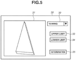
- the imaging position and orientation generation unit 102 may determine the imaging position and orientation within the range of the imaging position and orientation designated by the user. For example, in a case where photo-appearance of the target object to be recognized is previously known, the user may give an instruction about the imaging position and orientation limiting the position and orientation within that range. Thus, the learning accuracy can be improved. The method of giving the instruction about the imaging position and orientation from the user is described below with reference to FIG. 5 .
- FIG. 5 is a diagram illustrating an instruction screen 30 of the imaging position and orientation.
- the instruction screen 30 is displayed on the display unit 15 of the information processing device 100 and is presented to the user.
- the instruction screen 30 includes an image display section 31 on which a virtual captured image is displayed, and a designation section 32 for designation of motion of the imaging device 500 .
- the instruction screen 30 includes an upper limit button for designation of an upper limit value of the motion of the imaging device 500 , a lower limit button 34 for designation of a lower limit value of the motion of the imaging device 500 , and a determination button 35 for instructing end of inputting.
- the motion of the imaging device 500 include, yawing, rolling, pitching, parallel movement, etc.
- the user may operate the input unit 16 such as a mouse and a keyboard to perform button operation and input.
- the user selects the motion of the imaging device 500 from a pull-down list of the designation section 32 .
- the user gives an instruction for virtual movement of the imaging device 500 on the image displayed on the image display section 31 (e.g., through mouse drag)
- the target object is virtually presented to the user on the image display section 31 .
- the user gives the instruction for movement of the imaging device 500 on the image of the image display section 31 , and presses the upper limit button 33 at a position where a portion corresponding to the upper limit of the motion of the imaging device 500 appears, thereby determining the upper limit value of the motion of the imaging device 500 .
- the user gives the instruction for movement of the imaging device 500 on the image of the image display section 31 , and presses the lower limit button 34 at a position where a portion corresponding to the lower limit of the motion of the imaging device 500 appears, thereby determining the lower limit value of the motion of the imaging device 500 .
- the range of the imaging position and orientation is determined in the above-described manner. The user presses the determination button after finishing the necessary input.
- the user operates the image displayed on the image display section 31 to appropriately designate the range of the imaging position and orientation while confirming a way of photographing (a way of photo-presentation) of the target object which is important for learning.
- the user may directly input the numerical value (e.g., angle) to designate the upper limit value and the lower limit value of the motion of the imaging device 500 .
- the imaging position and orientation generation unit 102 may generate other states of the device.
- the control unit 103 may control a state of illumination (on/off and intensity of illumination) at the time of imaging the target object.
- the imaging position and orientation generation unit 102 may also generate a position and orientation of the illumination device provided in the robot, and the control unit 103 may control the robot including the imaging device 500 and the robot including the illumination device. This makes it possible to improve robustness of recognition of the target object that is easily influenced by illumination.
- the manipulator 400 moves the imaging device 500 ; however, the manipulator 400 may not move the imaging device 500 but move the target object.
- the robot in which a suction device is attached to the end effector may suction and move the target object, and the target object may be imaged in various positions and orientations by a stationary camera. This makes it possible to realize a recognizing device that recognizes the object suctioned by the robot.
- the image that has been cut out based on the learning information from the captured image is used for the learning data; however, the generation of the learning data is not limited to the above-described method.
- cutout of the image may not be performed, and in order to generate the learning data, the captured image as it is may be used as the image for learning.
- the learning data may be generated based on the image that has been subjected to geometric conversion such as enlargement/reduction and rotation, or to image processing such as imparting of noise and change of brightness (luminance value) or color in order to increase variation of photo-presentation.
- a plurality of portions may be cut out from one captured image, and each of the portions may be used for obtaining the learning data. In this case, since the plurality of pieces of learning data are generated from one captured image, it is possible to reduce time for capturing the image to be used for generation of the learning data.
- the images are obtained by imaging the target object from the plurality of imaging positions and orientations, and the acquired images are all used for generation of the learning data.
- the second exemplary embodiment a case of limiting data used for generation of the learning data is described.
- FIG. 6 is a block diagram illustrating a configuration of an object recognition apparatus 1000 A according to the second exemplary embodiment.
- components having configurations similar to those in FIG. 1 are denoted by the reference numerals same as those in FIG. 1 , and components having different configurations are mainly described below.
- the object recognition apparatus 1000 A includes an information processing device 100 A.
- the information processing device 100 A has a configuration similar to the configuration of the information processing device 100 illustrated in FIG. 1 except that a data set accumulation unit 107 and a data set extraction unit 108 are added to the information processing device 100 illustrated in FIG. 1 .
- the data set accumulation unit 107 receives the image that has been captured by the imaging device 500 and acquired by the image acquiring unit 104 , the imaging position and orientation generated by the imaging position and orientation generation unit 102 , and the learning information acquired by the learning information acquiring unit 101 .
- the data set accumulation unit 107 then generates and saves a data set that is a set of the received image, the received imaging position and orientation, and the received learning information.
- the data set extraction unit 108 extracts a necessary data set with use of at least one of the imaging position and orientation, and the learning information as a key, from the data sets accumulated by the data set accumulation unit 107 .
- the data set extraction unit 108 provides the extracted data set to the learning data generation unit 105 .
- the learning data generation unit 105 uses the data set extracted by the data set extraction unit 108 to generate the learning data.
- a flow of recognition processing by the object recognition apparatus 1000 A of the second exemplary embodiment is similar to the flow of the recognition processing ( FIG. 3A ) of the above-described first exemplary embodiment.
- the procedure of the learning data generation processing in step S 1 is different.
- FIG. 7 is a flowchart illustrating a procedure of the learning data generation processing executed by the information processing device 100 A in step S 1 of FIG. 3A .
- the processing of FIG. 7 is similar to the processing of FIG. 3B except that processes of steps S 18 to S 20 are added after step S 14 of FIG. 3B and the process in step S 17 is removed. Accordingly, a step in which the process same as the process of FIG. 3B is executed is denoted by the step number same as the step number of FIG. 3B , and steps with different processes are mainly described below.
- step S 18 the data set accumulation unit 107 receives the learning information, the imaging position and orientation, and the image, from the learning information acquiring unit 101 , the imaging position and orientation generation unit 102 , and the image acquiring unit 104 , respectively, and these are saved as a data set.
- step S 19 the information processing device 100 determines whether to end capturing of the image for generation of the learning data. The process in step S 19 is similar to the process in step S 17 of FIG. 3B .
- the data set extraction unit 108 may acquire a predetermined imaging position and orientation serving as a key, and extract a data set around the imaging position and orientation. This makes it possible to improve recognition performance.
- the key for extraction of the data set may be designated by the user through operation of the input screen.
- the learning information, the imaging position and orientation, and the image may be displayed on the input screen, and the user may input the key while confirming photo-presentation of the target object.
- the input screen may have a function of sorting the data set with use of the learning information and the imaging position and orientation serving as the key.
- the input screen has a function of browsing the data sets, which allows the user to efficiently select the data set to be extracted from the data sets generated in large quantities. In addition, it is possible for the user to easily confirm whether the collected data sets are appropriate.
- learning information may be newly acquired in the middle of or after the generation of the data set by the data set accumulation unit 107 .
- the data set accumulation unit 107 may receive the learning information newly acquired, and add the learning information to all of the data sets. Therefore, it is possible to generate different learning data with use of the images already captured. This makes it possible to reduce required work for recapturing the image.
- FIG. 8 is a block diagram illustrating a configuration of an object recognition apparatus 1000 B in the third exemplary embodiment.
- components having configurations similar to those in FIG. 6 are denoted by the reference numerals same as those in FIG. 6 , and components having different configurations are mainly described below.
- the object recognition apparatus 1000 B includes an information processing device 100 B.
- the information processing device 100 B has a configuration similar to the configuration of the information processing device 100 A illustrated in FIG. 6 except that an additional imaging determination unit 109 is added to the information processing device 100 A illustrated in FIG. 6 and the imaging position and orientation generation unit 102 is replaced with an imaging position and orientation generation unit 110 .
- a learning device 200 B learns a CNN model with use of the learning data saved in the learning data accumulation unit 106 and saves the CNN model, as performed by the above-described learning device 200 .
- the learning device 200 B provides recognition performance information that indicates a learning result, to the additional imaging determination unit 109 .
- the recognition performance information is information indicating recognition performance, and for example, is information relating to difference between the label of each piece of the learning data and the recognition result.
- the additional imaging determination unit 109 uses at least one of the recognition performance information provided from the learning device 200 B and the data set saved by the data set accumulation unit 107 , to determine whether additional generation of the learning data, namely, additional imaging of the target object is necessary. Further, when the additional imaging determination unit 109 determines that additional imaging of the target object is necessary, the additional imaging determination unit 109 determines a range of the imaging position and orientation at which the additional imaging is performed. The additional imaging determination unit 109 then provides a determination result to the imaging position and orientation generation unit 110 .
- FIG. 9 is a flowchart illustrating a flow of recognition processing by the object recognition apparatus 1000 B of the third exemplary embodiment.
- the processes in steps S 1 , S 2 , and S 3 are similar to those in the second exemplary embodiment.
- the additional imaging determination unit 109 of the information processing device 100 B determines in step S 4 whether additional imaging of the target object is necessary. More specifically, in a case where recognition performance is insufficient or recognition has failed when the learning has been carried out by the learning device 200 B, the additional imaging determination unit 109 determines that additional imaging of the target object is necessary in order to add the learning data. In a case where the additional imaging determination unit 109 determines that additional imaging is necessary (Yes in step S 4 ), the additional imaging determination unit 109 determines the range of the imaging position and orientation at which the additional imaging is required, and the processing returns to step S 1 .
- the additional imaging determination unit 109 determines that additional imaging of the target object is not necessary (No in step S 4 ), and the processing proceeds to step S 3 .
- the learning data may be generally increased as an improvement way.
- the additional imaging determination unit 109 determines that additional imaging is necessary over the entire range of the imaging position and orientation, and the imaging position and orientation generation unit 110 generates an additional imaging position and orientation on the whole such that imaging is performed at a denser imaging position and orientation.
- the imaging position and orientation generation unit 110 generates the additional imaging position and orientation such that the imaging is performed at a position that is farthest from the nearest imaging position and orientation at which imaging has been already performed because it is not effective to overlap imagings with one another in the vicinity of the imaging position at which the imaging has been already performed.
- the additional learning data can be efficiently generated, and the recognition performance can be improved on the whole.
- the information processing device 200 B can generate the additional learning data near the imaging position and orientation that does not achieve a good recognition performance in learning or near the imaging position and orientation where data quantity is low, so that the recognition performance can be improved.
- the information processing device 200 B determines the imaging position and orientation which is insufficient for learning from the learning result or the data sets, and automatically repeats the additional generation of the learning data and carries out relearning. Accordingly, it is possible to improve recognition performance while reducing work required for learning.
- the imaging device 500 obtains an RGB color image and a depth image.
- the imaging device 500 may be a device configured to obtain a monochrome image. Further, the imaging device 500 may be a device configured to obtain an infrared image.
- the manipulator 400 is a hexaxial robot; however, it is sufficient for the manipulator 400 to move at least one of the imaging device 500 and the target object.
- the manipulator 400 may be a multi-articulated robot, a parallel link robot, or an orthogonal robot.
- the manipulator 400 may be a movement mechanism other than the robot.
- the learning data accumulation unit 106 saves the learning data
- the learning device 200 performs learning of the CNN model; however, the learning is not limited thereto.
- the learning may be performed by inputting the learning data to the CNN model while generating the learning data.
- the CNN that is a kind of deep learning is learned to make up the recognizing device; however, the configuration is not limited thereto.
- the feature amount a local binary pattern (LBP), bag of features (BoF), etc. may be used.
- a decision tree, a support vector machine (SVM), etc. may be used as the recognizing device.
- the recognition result is used in the suction position of the robot; however, the recognition result may be used when a robot controls a guiding position or a direction of a tool, or may be used in inspection work, etc.
- the present disclosure can be realized by supplying a program that realizes one or more of the functions of the above-described embodiments, to a system or an apparatus through a network or a storage medium, and by reading and executing the program by one or more processors in a computer of the system or the apparatus. Further, the present disclosure is achievable by a circuit (e.g., application specific integrated circuit (ASIC)) that achieves one or more functions.
- ASIC application specific integrated circuit
- the present disclosure makes it possible to easily generate the learning data adaptable to the use application for recognizing the target object.
- Embodiment(s) of the present disclosure can also be realized by a computer of a system or apparatus that reads out and executes computer executable instructions (e.g., one or more programs) recorded on a storage medium (which may also be referred to more fully as a ‘non-transitory computer-readable storage medium’) to perform the functions of one or more of the above-described embodiment(s) and/or that includes one or more circuits (e.g., application specific integrated circuit (ASIC)) for performing the functions of one or more of the above-described embodiment(s), and by a method performed by the computer of the system or apparatus by, for example, reading out and executing the computer executable instructions from the storage medium to perform the functions of one or more of the above-described embodiment(s) and/or controlling the one or more circuits to perform the functions of one or more of the above-described embodiment(s).
- computer executable instructions e.g., one or more programs
- a storage medium which may also be referred to more fully as a
- the computer may comprise one or more processors (e.g., central processing unit (CPU), micro processing unit (MPU)) and may include a network of separate computers or separate processors to read out and execute the computer executable instructions.
- the computer executable instructions may be provided to the computer, for example, from a network or the storage medium.
- the storage medium may include, for example, one or more of a hard disk, a random-access memory (RAM), a read only memory (ROM), a storage of distributed computing systems, an optical disk (such as a compact disc (CD), digital versatile disc (DVD), or Blu-ray Disc (BD)TM), a flash memory device, a memory card, and the like.
Landscapes
- Engineering & Computer Science (AREA)
- Theoretical Computer Science (AREA)
- Data Mining & Analysis (AREA)
- Physics & Mathematics (AREA)
- General Physics & Mathematics (AREA)
- Bioinformatics & Cheminformatics (AREA)
- Computer Vision & Pattern Recognition (AREA)
- Evolutionary Biology (AREA)
- Evolutionary Computation (AREA)
- Bioinformatics & Computational Biology (AREA)
- General Engineering & Computer Science (AREA)
- Artificial Intelligence (AREA)
- Life Sciences & Earth Sciences (AREA)
- Multimedia (AREA)
- Image Analysis (AREA)
- Image Processing (AREA)
Applications Claiming Priority (3)
| Application Number | Priority Date | Filing Date | Title |
|---|---|---|---|
| JP2017-008219 | 2017-01-20 | ||
| JP2017008219A JP7071054B2 (ja) | 2017-01-20 | 2017-01-20 | 情報処理装置、情報処理方法およびプログラム |
| JPJP2017-008219 | 2017-01-20 |
Publications (2)
| Publication Number | Publication Date |
|---|---|
| US20180211138A1 US20180211138A1 (en) | 2018-07-26 |
| US10997465B2 true US10997465B2 (en) | 2021-05-04 |
Family
ID=62906546
Family Applications (1)
| Application Number | Title | Priority Date | Filing Date |
|---|---|---|---|
| US15/873,813 Active 2038-06-07 US10997465B2 (en) | 2017-01-20 | 2018-01-17 | Information processing device, information processing method, and storage medium |
Country Status (2)
| Country | Link |
|---|---|
| US (1) | US10997465B2 (enExample) |
| JP (1) | JP7071054B2 (enExample) |
Families Citing this family (21)
| Publication number | Priority date | Publication date | Assignee | Title |
|---|---|---|---|---|
| US20190236360A1 (en) * | 2018-01-30 | 2019-08-01 | Mashgin Inc. | Feedback loop for image-based recognition |
| JP6737824B2 (ja) * | 2018-03-13 | 2020-08-12 | ファナック株式会社 | 制御装置、制御方法及び制御プログラム |
| JP7403834B2 (ja) * | 2018-07-17 | 2023-12-25 | 株式会社Synapse Gear | 撮像装置と撮像方法 |
| JP6814775B2 (ja) * | 2018-10-04 | 2021-01-20 | 東芝インフォメーションシステムズ株式会社 | 収集装置、収集方法及び収集プログラム |
| TWI684925B (zh) * | 2018-10-17 | 2020-02-11 | 新漢智能系統股份有限公司 | 自動建立物件辨識模型的方法 |
| JP7200610B2 (ja) * | 2018-11-08 | 2023-01-10 | 富士通株式会社 | 位置検出プログラム、位置検出方法及び位置検出装置 |
| US12423770B2 (en) | 2019-01-15 | 2025-09-23 | Sony Interactive Entertainment Inc. | Information processing apparatus |
| JP7200713B2 (ja) * | 2019-02-04 | 2023-01-10 | 株式会社島津製作所 | 機械学習用教師データ作成支援方法、及び機械学習用教師データ作成支援プログラム |
| JP2020149086A (ja) * | 2019-03-11 | 2020-09-17 | オムロン株式会社 | 学習用データ生成装置、学習用データ生成方法、および学習用データ生成プログラム |
| JP2020166371A (ja) | 2019-03-28 | 2020-10-08 | セイコーエプソン株式会社 | 情報処理方法、情報処理装置、物体検出装置およびロボットシステム |
| JP7407427B2 (ja) * | 2019-04-04 | 2024-01-04 | パナソニックIpマネジメント株式会社 | 情報処理方法、及び、情報処理システム |
| JP2020186082A (ja) * | 2019-05-13 | 2020-11-19 | Jfeアーバンリサイクル株式会社 | 洗濯機識別システム |
| US11176429B2 (en) * | 2019-05-13 | 2021-11-16 | International Business Machines Corporation | Counter rare training date for artificial intelligence |
| JP7266008B2 (ja) * | 2020-03-24 | 2023-04-27 | 株式会社 日立産業制御ソリューションズ | 学習画像判定装置、プログラムおよび学習画像判定方法 |
| JP7748401B2 (ja) * | 2020-06-24 | 2025-10-02 | マジック リープ, インコーポレイテッド | アモーダル中心予測のためのオブジェクト認識ニューラルネットワーク |
| JP7595430B2 (ja) * | 2020-07-16 | 2024-12-06 | キヤノン株式会社 | 情報処理装置及び方法、撮像装置、及び撮像システム |
| JP7553754B2 (ja) * | 2020-08-25 | 2024-09-19 | 公立大学法人会津大学 | 学習プログラム、学習装置及び学習方法 |
| CN116635887A (zh) * | 2020-12-15 | 2023-08-22 | 索尼集团公司 | 信息处理装置、信息处理系统、信息处理方法和程序 |
| JP7735814B2 (ja) * | 2021-11-18 | 2025-09-09 | セイコーエプソン株式会社 | 機械学習モデルの学習に用いる教師データを作成する方法、システム、及び、コンピュータープログラム |
| JP2023173603A (ja) * | 2022-05-26 | 2023-12-07 | セイコーエプソン株式会社 | 物体の位置姿勢を認識する方法、システム、及び、コンピュータープログラム |
| JP2026054868A (ja) * | 2024-09-17 | 2026-03-30 | 株式会社日立製作所 | 撮影支援装置、撮影システムおよび撮影支援方法 |
Citations (33)
| Publication number | Priority date | Publication date | Assignee | Title |
|---|---|---|---|---|
| US6259960B1 (en) * | 1996-11-01 | 2001-07-10 | Joel Ltd. | Part-inspecting system |
| US20010009135A1 (en) * | 1996-02-01 | 2001-07-26 | Keizo Hasebe | Film forming method and film forming apparatus |
| US20020050988A1 (en) * | 2000-03-28 | 2002-05-02 | Michael Petrov | System and method of three-dimensional image capture and modeling |
| US20040247174A1 (en) * | 2000-01-20 | 2004-12-09 | Canon Kabushiki Kaisha | Image processing apparatus |
| US20050237581A1 (en) * | 2004-04-21 | 2005-10-27 | Knighton Mark S | Hand held portable three dimensional scanner |
| US20060233423A1 (en) * | 2005-04-19 | 2006-10-19 | Hesam Najafi | Fast object detection for augmented reality systems |
| US20080095416A1 (en) * | 2006-10-18 | 2008-04-24 | Varian Medical Systems Technologies, Inc. | Marker system and method of using the same |
| US20090096790A1 (en) * | 2007-10-11 | 2009-04-16 | Mvtec Software Gmbh | System and method for 3d object recognition |
| US20090123045A1 (en) * | 2007-11-08 | 2009-05-14 | D4D Technologies, Llc | Lighting Compensated Dynamic Texture Mapping of 3-D Models |
| US20090213219A1 (en) * | 2007-12-11 | 2009-08-27 | Honda Research Institute Europe Gmbh | Visually tracking an object in real world using 2d appearance and multicue depth estimations |
| US20100191391A1 (en) * | 2009-01-26 | 2010-07-29 | Gm Global Technology Operations, Inc. | multiobject fusion module for collision preparation system |
| JP2010218051A (ja) | 2009-03-13 | 2010-09-30 | Nec Corp | 特徴点選択システム、特徴点選択方法および特徴点選択プログラム |
| US7831086B2 (en) * | 2002-06-03 | 2010-11-09 | Sony Corporation | Image processing device and method, program, program recording medium, data structure, and data recording medium |
| US20110115899A1 (en) * | 2008-07-14 | 2011-05-19 | Panasonic Corporation | Component mount system |
| US20110206237A1 (en) * | 2010-02-25 | 2011-08-25 | Canon Kabushiki Kaisha | Recognition apparatus and method thereof, and computer program |
| JP2012028949A (ja) | 2010-07-21 | 2012-02-09 | Canon Inc | 画像処理装置及びその制御方法 |
| US8115761B1 (en) * | 2010-10-12 | 2012-02-14 | Google Inc. | Locking geometric and camera parameters in image-based three-dimensional modeling, and applications thereof |
| JP2012088787A (ja) | 2010-10-15 | 2012-05-10 | Canon Inc | 画像処理装置、画像処理方法 |
| US20120182392A1 (en) * | 2010-05-20 | 2012-07-19 | Irobot Corporation | Mobile Human Interface Robot |
| US20120201469A1 (en) * | 2009-10-20 | 2012-08-09 | Total Immersion | Method, computer program and device for hybrid tracking of real-time representations of objects in a sequence |
| US20120321134A1 (en) * | 2011-06-15 | 2012-12-20 | Samsung Electornics Co., Ltd | Face tracking method and device |
| US20130230235A1 (en) * | 2010-11-19 | 2013-09-05 | Canon Kabushiki Kaisha | Information processing apparatus and information processing method |
| JP2013541775A (ja) | 2010-10-21 | 2013-11-14 | ゼンロボティクス オイ | ロボットシステムにおける対象物体画像のフィルタ方法 |
| US20130343640A1 (en) * | 2012-06-21 | 2013-12-26 | Rethink Robotics, Inc. | Vision-guided robots and methods of training them |
| US8805034B2 (en) * | 2006-08-11 | 2014-08-12 | Koninklijke Philips N.V. | Selection of datasets from 3D renderings for viewing |
| JP2014178957A (ja) | 2013-03-15 | 2014-09-25 | Nec Corp | 学習データ生成装置、学習データ作成システム、方法およびプログラム |
| JP2014199584A (ja) | 2013-03-29 | 2014-10-23 | キヤノン株式会社 | 画像処理装置および画像処理方法 |
| US20150243031A1 (en) * | 2014-02-21 | 2015-08-27 | Metaio Gmbh | Method and device for determining at least one object feature of an object comprised in an image |
| US20160034746A1 (en) * | 2014-07-29 | 2016-02-04 | Seiko Epson Corporation | Control system, robot system, and control method |
| US20160154994A1 (en) * | 2014-12-02 | 2016-06-02 | Samsung Electronics Co., Ltd. | Method and apparatus for registering face, and method and apparatus for recognizing face |
| US20160217318A1 (en) * | 2013-08-29 | 2016-07-28 | Nec Corporation | Image processing device, image processing method, and program |
| US20170151027A1 (en) * | 2015-11-30 | 2017-06-01 | Hansen Medical, Inc. | Robot-assisted driving systems and methods |
| US20180039848A1 (en) * | 2016-08-03 | 2018-02-08 | X Development Llc | Generating a model for an object encountered by a robot |
-
2017
- 2017-01-20 JP JP2017008219A patent/JP7071054B2/ja active Active
-
2018
- 2018-01-17 US US15/873,813 patent/US10997465B2/en active Active
Patent Citations (33)
| Publication number | Priority date | Publication date | Assignee | Title |
|---|---|---|---|---|
| US20010009135A1 (en) * | 1996-02-01 | 2001-07-26 | Keizo Hasebe | Film forming method and film forming apparatus |
| US6259960B1 (en) * | 1996-11-01 | 2001-07-10 | Joel Ltd. | Part-inspecting system |
| US20040247174A1 (en) * | 2000-01-20 | 2004-12-09 | Canon Kabushiki Kaisha | Image processing apparatus |
| US20020050988A1 (en) * | 2000-03-28 | 2002-05-02 | Michael Petrov | System and method of three-dimensional image capture and modeling |
| US7831086B2 (en) * | 2002-06-03 | 2010-11-09 | Sony Corporation | Image processing device and method, program, program recording medium, data structure, and data recording medium |
| US20050237581A1 (en) * | 2004-04-21 | 2005-10-27 | Knighton Mark S | Hand held portable three dimensional scanner |
| US20060233423A1 (en) * | 2005-04-19 | 2006-10-19 | Hesam Najafi | Fast object detection for augmented reality systems |
| US8805034B2 (en) * | 2006-08-11 | 2014-08-12 | Koninklijke Philips N.V. | Selection of datasets from 3D renderings for viewing |
| US20080095416A1 (en) * | 2006-10-18 | 2008-04-24 | Varian Medical Systems Technologies, Inc. | Marker system and method of using the same |
| US20090096790A1 (en) * | 2007-10-11 | 2009-04-16 | Mvtec Software Gmbh | System and method for 3d object recognition |
| US20090123045A1 (en) * | 2007-11-08 | 2009-05-14 | D4D Technologies, Llc | Lighting Compensated Dynamic Texture Mapping of 3-D Models |
| US20090213219A1 (en) * | 2007-12-11 | 2009-08-27 | Honda Research Institute Europe Gmbh | Visually tracking an object in real world using 2d appearance and multicue depth estimations |
| US20110115899A1 (en) * | 2008-07-14 | 2011-05-19 | Panasonic Corporation | Component mount system |
| US20100191391A1 (en) * | 2009-01-26 | 2010-07-29 | Gm Global Technology Operations, Inc. | multiobject fusion module for collision preparation system |
| JP2010218051A (ja) | 2009-03-13 | 2010-09-30 | Nec Corp | 特徴点選択システム、特徴点選択方法および特徴点選択プログラム |
| US20120201469A1 (en) * | 2009-10-20 | 2012-08-09 | Total Immersion | Method, computer program and device for hybrid tracking of real-time representations of objects in a sequence |
| US20110206237A1 (en) * | 2010-02-25 | 2011-08-25 | Canon Kabushiki Kaisha | Recognition apparatus and method thereof, and computer program |
| US20120182392A1 (en) * | 2010-05-20 | 2012-07-19 | Irobot Corporation | Mobile Human Interface Robot |
| JP2012028949A (ja) | 2010-07-21 | 2012-02-09 | Canon Inc | 画像処理装置及びその制御方法 |
| US8115761B1 (en) * | 2010-10-12 | 2012-02-14 | Google Inc. | Locking geometric and camera parameters in image-based three-dimensional modeling, and applications thereof |
| JP2012088787A (ja) | 2010-10-15 | 2012-05-10 | Canon Inc | 画像処理装置、画像処理方法 |
| JP2013541775A (ja) | 2010-10-21 | 2013-11-14 | ゼンロボティクス オイ | ロボットシステムにおける対象物体画像のフィルタ方法 |
| US20130230235A1 (en) * | 2010-11-19 | 2013-09-05 | Canon Kabushiki Kaisha | Information processing apparatus and information processing method |
| US20120321134A1 (en) * | 2011-06-15 | 2012-12-20 | Samsung Electornics Co., Ltd | Face tracking method and device |
| US20130343640A1 (en) * | 2012-06-21 | 2013-12-26 | Rethink Robotics, Inc. | Vision-guided robots and methods of training them |
| JP2014178957A (ja) | 2013-03-15 | 2014-09-25 | Nec Corp | 学習データ生成装置、学習データ作成システム、方法およびプログラム |
| JP2014199584A (ja) | 2013-03-29 | 2014-10-23 | キヤノン株式会社 | 画像処理装置および画像処理方法 |
| US20160217318A1 (en) * | 2013-08-29 | 2016-07-28 | Nec Corporation | Image processing device, image processing method, and program |
| US20150243031A1 (en) * | 2014-02-21 | 2015-08-27 | Metaio Gmbh | Method and device for determining at least one object feature of an object comprised in an image |
| US20160034746A1 (en) * | 2014-07-29 | 2016-02-04 | Seiko Epson Corporation | Control system, robot system, and control method |
| US20160154994A1 (en) * | 2014-12-02 | 2016-06-02 | Samsung Electronics Co., Ltd. | Method and apparatus for registering face, and method and apparatus for recognizing face |
| US20170151027A1 (en) * | 2015-11-30 | 2017-06-01 | Hansen Medical, Inc. | Robot-assisted driving systems and methods |
| US20180039848A1 (en) * | 2016-08-03 | 2018-02-08 | X Development Llc | Generating a model for an object encountered by a robot |
Non-Patent Citations (1)
| Title |
|---|
| Efficient Learning Method for Human Detection based on Automatic Generation of Training Samples with the Negative-Bag MILBoost;Graduate School of Engineering,(3hubu University,1200 Matsumoto, Kasugai,Aichi,487-8501 Japan. |
Also Published As
| Publication number | Publication date |
|---|---|
| US20180211138A1 (en) | 2018-07-26 |
| JP7071054B2 (ja) | 2022-05-18 |
| JP2018116599A (ja) | 2018-07-26 |
Similar Documents
| Publication | Publication Date | Title |
|---|---|---|
| US10997465B2 (en) | Information processing device, information processing method, and storage medium | |
| EP3284011B1 (en) | Two-dimensional infrared depth sensing | |
| US8442269B2 (en) | Method and apparatus for tracking target object | |
| JP6732214B2 (ja) | 画像処理装置、画像処理方法、テンプレート作成装置、物体認識処理装置及びプログラム | |
| US9805443B2 (en) | Image processing method, image processing apparatus, program, storage medium, production apparatus, and method of producing assembly | |
| CN111598065B (zh) | 深度图像获取方法及活体识别方法、设备、电路和介质 | |
| US10572762B2 (en) | Image processing method for performing pattern matching for detecting a position of a detection target | |
| US11989928B2 (en) | Image processing system | |
| US9595095B2 (en) | Robot system | |
| JP6141108B2 (ja) | 情報処理装置およびその方法 | |
| US10207409B2 (en) | Image processing method, image processing device, and robot system | |
| JP2013206458A (ja) | 画像における外観及びコンテキストに基づく物体分類 | |
| EP4372679A1 (en) | Recognition model generation method and recognition model generation device | |
| KR101501487B1 (ko) | 깊이 영상 기반 머리 검출방법 및 장치 | |
| US9507433B1 (en) | System and method for discerning complex gestures using an array of optical sensors | |
| US20180191951A1 (en) | Imaging apparatus and imaging condition setting method and program | |
| WO2005041128A1 (ja) | 顔画像候補領域検索方法及び顔画像候補領域検索システム並びに顔画像候補領域検索プログラム | |
| CN108521820A (zh) | 使用深度神经网络的从粗略到精细的手部检测方法 | |
| JP2017033556A (ja) | 画像処理方法及び電子機器 | |
| JP6350331B2 (ja) | 追尾装置、追尾方法及び追尾プログラム | |
| JP2006323779A (ja) | 画像処理方法、画像処理装置 | |
| JP5713655B2 (ja) | 映像処理装置、映像処理方法及びプログラム | |
| US20220101491A1 (en) | Information processing apparatus | |
| JP6624861B2 (ja) | 画像処理装置、制御方法およびプログラム | |
| JP2016045707A (ja) | 特徴点検出システム、特徴点検出方法、および特徴点検出プログラム |
Legal Events
| Date | Code | Title | Description |
|---|---|---|---|
| FEPP | Fee payment procedure |
Free format text: ENTITY STATUS SET TO UNDISCOUNTED (ORIGINAL EVENT CODE: BIG.); ENTITY STATUS OF PATENT OWNER: LARGE ENTITY |
|
| STPP | Information on status: patent application and granting procedure in general |
Free format text: DOCKETED NEW CASE - READY FOR EXAMINATION |
|
| AS | Assignment |
Owner name: CANON KABUSHIKI KAISHA, JAPAN Free format text: ASSIGNMENT OF ASSIGNORS INTEREST;ASSIGNORS:YAMADA, TAKAYUKI;KATAYAMA, AKIHIRO;KOBAYASHI, KAZUHIKO;SIGNING DATES FROM 20171218 TO 20171220;REEL/FRAME:045852/0961 |
|
| STPP | Information on status: patent application and granting procedure in general |
Free format text: NON FINAL ACTION MAILED |
|
| STPP | Information on status: patent application and granting procedure in general |
Free format text: FINAL REJECTION MAILED |
|
| STPP | Information on status: patent application and granting procedure in general |
Free format text: RESPONSE AFTER FINAL ACTION FORWARDED TO EXAMINER |
|
| STPP | Information on status: patent application and granting procedure in general |
Free format text: ADVISORY ACTION MAILED |
|
| STPP | Information on status: patent application and granting procedure in general |
Free format text: DOCKETED NEW CASE - READY FOR EXAMINATION |
|
| STPP | Information on status: patent application and granting procedure in general |
Free format text: NON FINAL ACTION MAILED |
|
| STPP | Information on status: patent application and granting procedure in general |
Free format text: RESPONSE TO NON-FINAL OFFICE ACTION ENTERED AND FORWARDED TO EXAMINER |
|
| STPP | Information on status: patent application and granting procedure in general |
Free format text: RESPONSE AFTER FINAL ACTION FORWARDED TO EXAMINER |
|
| STPP | Information on status: patent application and granting procedure in general |
Free format text: NOTICE OF ALLOWANCE MAILED -- APPLICATION RECEIVED IN OFFICE OF PUBLICATIONS |
|
| STPP | Information on status: patent application and granting procedure in general |
Free format text: NOTICE OF ALLOWANCE MAILED -- APPLICATION RECEIVED IN OFFICE OF PUBLICATIONS |
|
| STPP | Information on status: patent application and granting procedure in general |
Free format text: PUBLICATIONS -- ISSUE FEE PAYMENT VERIFIED |
|
| STCF | Information on status: patent grant |
Free format text: PATENTED CASE |
|
| MAFP | Maintenance fee payment |
Free format text: PAYMENT OF MAINTENANCE FEE, 4TH YEAR, LARGE ENTITY (ORIGINAL EVENT CODE: M1551); ENTITY STATUS OF PATENT OWNER: LARGE ENTITY Year of fee payment: 4 |