US10940586B2 - Method for correcting target position of work robot - Google Patents
Method for correcting target position of work robot Download PDFInfo
- Publication number
- US10940586B2 US10940586B2 US16/466,072 US201616466072A US10940586B2 US 10940586 B2 US10940586 B2 US 10940586B2 US 201616466072 A US201616466072 A US 201616466072A US 10940586 B2 US10940586 B2 US 10940586B2
- Authority
- US
- United States
- Prior art keywords
- block
- target position
- work robot
- blocks
- amount
- Prior art date
- Legal status (The legal status is an assumption and is not a legal conclusion. Google has not performed a legal analysis and makes no representation as to the accuracy of the status listed.)
- Active, expires
Links
Images


Classifications
-
- B—PERFORMING OPERATIONS; TRANSPORTING
- B25—HAND TOOLS; PORTABLE POWER-DRIVEN TOOLS; MANIPULATORS
- B25J—MANIPULATORS; CHAMBERS PROVIDED WITH MANIPULATION DEVICES
- B25J9/00—Program-controlled manipulators
- B25J9/16—Program controls
- B25J9/1628—Program controls characterised by the control loop
- B25J9/163—Program controls characterised by the control loop learning, adaptive, model based, rule based expert control
-
- B—PERFORMING OPERATIONS; TRANSPORTING
- B25—HAND TOOLS; PORTABLE POWER-DRIVEN TOOLS; MANIPULATORS
- B25J—MANIPULATORS; CHAMBERS PROVIDED WITH MANIPULATION DEVICES
- B25J9/00—Program-controlled manipulators
- B25J9/16—Program controls
- B25J9/1656—Program controls characterised by programming, planning systems for manipulators
- B25J9/1664—Program controls characterised by programming, planning systems for manipulators characterised by motion, path, trajectory planning
-
- B—PERFORMING OPERATIONS; TRANSPORTING
- B25—HAND TOOLS; PORTABLE POWER-DRIVEN TOOLS; MANIPULATORS
- B25J—MANIPULATORS; CHAMBERS PROVIDED WITH MANIPULATION DEVICES
- B25J9/00—Program-controlled manipulators
- B25J9/10—Program-controlled manipulators characterised by positioning means for manipulator elements
- B25J9/1005—Program-controlled manipulators characterised by positioning means for manipulator elements comprising adjusting means
-
- G—PHYSICS
- G05—CONTROLLING; REGULATING
- G05B—CONTROL OR REGULATING SYSTEMS IN GENERAL; FUNCTIONAL ELEMENTS OF SUCH SYSTEMS; MONITORING OR TESTING ARRANGEMENTS FOR SUCH SYSTEMS OR ELEMENTS
- G05B19/00—Program-control systems
- G05B19/02—Program-control systems electric
- G05B19/18—Numerical control [NC], i.e. automatically operating machines, in particular machine tools, e.g. in a manufacturing environment, so as to execute positioning, movement or co-ordinated operations by means of program data in numerical form
- G05B19/408—Numerical control [NC], i.e. automatically operating machines, in particular machine tools, e.g. in a manufacturing environment, so as to execute positioning, movement or co-ordinated operations by means of program data in numerical form characterised by data handling or data format, e.g. reading, buffering or conversion of data
- G05B19/4083—Adapting program, configuration
-
- G—PHYSICS
- G05—CONTROLLING; REGULATING
- G05B—CONTROL OR REGULATING SYSTEMS IN GENERAL; FUNCTIONAL ELEMENTS OF SUCH SYSTEMS; MONITORING OR TESTING ARRANGEMENTS FOR SUCH SYSTEMS OR ELEMENTS
- G05B2219/00—Program-control systems
- G05B2219/30—Nc systems
- G05B2219/36—Nc in input of data, input key till input tape
- G05B2219/36416—Adapt teached position as function of deviation 3-D, 2-D position of end effector, tool
-
- G—PHYSICS
- G05—CONTROLLING; REGULATING
- G05B—CONTROL OR REGULATING SYSTEMS IN GENERAL; FUNCTIONAL ELEMENTS OF SUCH SYSTEMS; MONITORING OR TESTING ARRANGEMENTS FOR SUCH SYSTEMS OR ELEMENTS
- G05B2219/00—Program-control systems
- G05B2219/30—Nc systems
- G05B2219/36—Nc in input of data, input key till input tape
- G05B2219/36504—Adapt program to real coordinates, shape, dimension of tool, offset path
Definitions
- the present description discloses a method for correcting a target position of a work robot.
- DH parameter are set as follows. That is, a control device of a robot divides an operation space for the robot into multiple regions and sets a measurement point for each of the divided regions. Next, the control device moves the robot to the measurement points to acquire three-dimensional position data. Then, the control device derives a DH parameter from an error between the acquired position data and the measurement point.
- the control device selects, in DH parameters derived individually for the multiple regions, a DH parameter of the region involving the target point and performs a coordinate transformation by applying the selected DH parameter to the target point.
- An object of the present disclosure is to position a work robot in a target position designated in an operation space of a three-dimensional matrix with good accuracy.
- the two blocks contiguous with the specific block including the target position are set as the first block and the second block. Then, the target position is corrected based on the respective reference points in the upper arear and the lower area of the specific block and the measured deviation amount of the work robot from the reference points, the respective reference points in the upper area and the lower area of the first block and the measured deviation amount of the work robot from the reference points, and the respective reference points in the upper area and the lower area of the second block and the measured deviation amount of the work robot from the reference points. In this manner, the target position is corrected by making use of not only the measured deviation amount from the reference points of the specific block but also the measured deviation amount from the reference points of the two blocks that are contiguous with the specific block. Consequently, the work robot can be positioned in the target position designated in the operation space of the three-dimensional matrix with good accuracy.
- FIG. 1 is a block diagram illustrating a schematic configuration of robot system 10 .
- FIG. 2 illustrates three-dimensional matrix 25 .
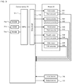
- FIG. 3 is a block diagram illustrating an electrical connection relationship between robot 20 and control device 70 .
- FIG. 4 is a flowchart of a pre-correction process routine.
- FIG. 5 illustrates a relationship between reference point R and measurement point M.
- FIG. 6 is a flowchart of a target position correction routine.
- FIG. 7A is a top view of specific block Bs with target position T residing in left front zone a 1 .
- FIG. 7B illustrates first and second blocks B 1 , B 2 with target position T residing in left front zone a 1 .
- FIG. 8A is a top view of specific block Bs with target position T residing in right front zone a 2 .
- FIG. 8B illustrates first and second blocks B 1 and B 2 with target position T residing in right front zone a 2 .
- FIG. 9A is a top view of specific block Bs with target position T residing in left rear zone a 3 .
- FIG. 9B illustrates first and second blocks B 1 and B 2 with target position residing in left rear zone a 3 .
- FIG. 10A is a top view of specific block Bs with target position T residing in right rear zone a 4 .
- FIG. 10B illustrates first and second blocks B 1 and B 2 when the target position T is in the right rear zone a 4 .
- FIG. 11 illustrates how to obtain a hypothetical projection point HP of specific block Bs.
- FIG. 12 illustrates a calculation method of correction amounts ⁇ xt, ⁇ yt.
- FIG. 13 illustrates how to obtain a hypothetical measurement point HM of specific block Bs.
- FIG. 14 is a view of FIG. 13 as viewed from a direction indicated by an arrow A illustrated therein.
- FIG. 15 illustrates an inclined plane including hypothetical measurement points HMs, HM 1 , and HM 2 .
- FIG. 1 is a block diagram illustrating a schematic configuration of robot system 10 .
- FIG. 2 illustrates three-dimensional matrix 25 .
- FIG. 3 is a block diagram illustrating an electrical connection relationship between robot 20 and control device 70 .
- a left-right direction is referred to as an X-axis direction
- a front-rear direction is referred to as a Y-axis direction
- an up-down direction is referred to as a Z-axis direction.
- Robot system 10 includes robot 20 and control device 70 configured to control robot 20 .
- Robot system 10 constitutes a system configured to pick up a workpiece and place the workpiece picked up on a target object.
- robot system 10 can be applied to any system, provided that the system is such that a workpiece is handled using robot 20 .
- robot system 10 can be applied to a component mounting system in which robot 20 picks up components and mounts them on a board.
- Robot 20 includes a five-axis vertical articulated arm (hereinafter, referred to as an arm) 22 and end effector 23 , not shown, which constitutes a hand of robot 20 .
- Arm 22 includes six links (first to sixth links 31 to 36 ) and five joints (first to fifth joints 41 to 45 ) which couple the links so as to rotate or swing.
- the individual joints (first to fifth joints 41 to 45 ) include motors (first to fifth motors 51 to 55 , refer to FIG. 3 ) configured to drive the corresponding joints and encoders (first to fifth encoders 61 . to 65 ) configured to detect a rotation angle of the corresponding motors.
- the motors are servomotors
- the encoders are rotary encoders.
- End effector 23 is attached to a distal end link (sixth link 36 ) of arm 22 and can hold and release a component (workpiece).
- a component for example, a mechanical chuck, a suction nozzle, an electromagnet, and the like can be used for the end effector 23 .
- Three-dimensional matrix 25 constitutes an operation space for robot 20 .
- a distal end of end effector 23 of robot 20 is moved to the target position by control device 70 , which will be described in detail later.
- Three-dimensional matrix 25 is fabricated by piling up matrix planes P at predetermined intervals in a Z-direction. Nth matrix plane P from a bottom of three-dimensional matrix 25 is referred to as matrix plane P n (n is a natural number).
- a height or z-coordinate of matrix plan P n is denoted by z n .
- Matrix plane P is made by continuously connecting together multiple rectangular areas A, which are parallel to an XY-plane and each have a reference point R at a center thereof, in XY-directions.
- Reference point R is set on world coordinates (absolute coordinates). Coordinates of all reference points R are stored in HDD 73 in advance.
- a rectangular parallelepiped space including a pair of upper and lower areas A disposed at a predetermined interval is referred to as block B.
- control device 70 is configured as a microprocessor mainly made up of CPU 71 and includes, in addition to CPU 71 , ROM 72 , HDD 73 , RAM 74 , drive circuit 75 , and the like.
- Drive circuit 75 drives first to fifth motors 51 to 55 .
- Signals are input into control device 70 from first to fifth encoders 61 to 65 , input device 76 , and the like.
- Signals are output from control device 70 to output device 77 and first to fifth motors 51 to 55 .
- Input device 76 is an input device on which an operator performs an input operation.
- Output device 77 is a display device configured to display various types of information thereon.
- FIG. 6 is a flowchart of a target position correction routine.
- Robot system 10 executes a pre-correction process routine before robot system 10 executes the target position correction routine, and therefore, firstly, the pre-correction process routine will be described, whereafter the target position correction routine will be described.
- FIG. 4 is a flowchart of the pre-correction process routine.
- CPU 71 of control device 70 reads out coordinates of one reference point R (S 100 ) and controls robot 20 so that the distal end of end effector 23 of robot 20 coincides with the coordinates (S 110 ).
- CPU 71 recognizes an actual stopping position then of the distal end of end effector 23 on the world coordinates (S 120 ) and stores the stopping position as a measurement point M in HDD 73 in association with current reference point R (S 130 ).
- CPU 71 determines whether the pre-correction process routine ends, that is, determines whether measurement points M are stored while being individually associated with all reference points R (S 140 ). If the determination result is negative, CPU 71 returns to S 100 to execute a similar process on next reference point R. On the other hand, if the result of the determination is affirmative, CPU 71 ends this pre-correction process routine.
- FIG. 5 is an explanatory diagram illustrating a relationship between reference point R and measurement point M of block B where area A at height z 1 and area A at height z 2 make a pair of upper and lower areas.
- reference point R In area A at height z 1 , reference point R is (x r , y r , z 1 ), and measurement point M is (x r1 , y r1 , z r1 ), and in area A at height z 2 , reference point R is (x r , y r , z 2 ), and measurement point M is (x r2 , y r2 , z r2 ).
- the target position correction routine is a correction routine in which target position T input into robot 20 is corrected for the distal end of end effector 23 to be positioned in target portion T with good accuracy.
- CPU 71 When the target position correction routine is started, firstly, CPU 71 reads out coordinates (x t , y t , z t ) of current target position (S 200 ). The coordinates (x t , y t , z t ) of target position T are input into robot 20 in advance by an operator via input device 76 and are stored in HDD 73 . Next, CPU 71 sets specific block Bs (S 210 ). Specifically, block B including target position T on the world coordinates is set as specific block Bs.
- CPU 71 sets first and second blocks B 1 and B 2 (S 220 ).
- CPU 71 sets first and second blocks B 1 and B 2 from blocks B that are contiguous with specific block Bs.
- specific block Bs is divided into four zones of left front zone a 1 , right front zone a 2 , left rear zone a 3 , and right rear zone a 4 .
- CPU 71 recognizes which zone includes target position T and sets blocks that are individually contiguous with two external surfaces of the recognized zone as first and second blocks B 1 and B 2 .
- left front zone a 1 includes target position T.
- FIG. 7A left front zone a 1 includes target position T. In this case, as illustrated in FIG.
- left and front blocks that are contiguous individually with two external surfaces (refer to thick solid lines in FIG. 7A ) of left front zone a 1 are set as first and second blocks B 1 and B 2 .
- right front zone a 2 includes target position T.
- the right and front blocks that are contiguous individually with two external surfaces (refer to thick solid lines in FIG. 8A ) of right front zone a 2 are set as first and second blocks B 1 and B 2 .
- left rear zone a 3 includes target position T. In this case, as illustrated in FIG.
- left and rear blocks that are contiguous individually with two external surfaces (refer to thick solid lines in FIG. 9A ) of left rear zone a 3 are set as first and second blocks B 1 and B 2 .
- right rear zone a 4 includes target position T.
- the right and rear blocks that are contiguous individually with two external surfaces (refer to thick solid lines in FIG. 10A ) of right rear zone a 4 are set as first and second blocks B 1 and B 2 .
- CPU 71 calculates correction amounts ⁇ x t and ⁇ y t of target position T in the X- and Y-directions (S 230 ).
- CPU 71 calculates correction amounts ⁇ x t and ⁇ y t in the X- and Y-directions of target position T without taking the amount of deviation of target position T in a Z-direction into consideration.
- CPU 71 obtains a hypothetical projection point HP on an XY-plane at target position height z t for each of specific block Bs, first and second blocks B 1 and B 2 .
- a method for obtaining hypothetical projection point HP of specific block Bs will be described by reference to FIG. 11 .
- Specific block Bs includes a pair of upper and lower areas A. It is assumed that a height of lower area A is z 1 and a height of upper area A is z 2 .
- Measurement point M (x s1 , y s1 , z s1 ) of reference point R (x s , y s , z 1 ) in lower area A resides in a position deviating by the measured deviation amount from reference point R thereof.
- a point (xs 1 , ys 1 , z 1 ) where this measurement point M (xs 1 , ys 1 , zs 1 ) is projected onto lower area A is referred to as lower projection point LP.
- Lower projection point LP can be referred to as a measurement point that does not take the amount of deviation in the Z-direction into consideration.
- measurement point M (x s2 , y s2 , z s2 ) of reference point R (x s , y s , z 2 ) in upper area A resides in a position deviating by the measured deviation amount from reference point R thereof.
- a point (x s2 , y s2 , z 2 ) where this measurement point M (x s2 , y s2 , z s2 ) is projected onto upper area A is referred to as upper projection point UP.
- Upper projection point UP can be referred to as a measurement point that does not take the amount of deviation in the Z-direction into consideration.
- intersection point is obtained mathematically, the intersection point being where a straight line connecting lower projection point LP with upper projection point UP intersects an XY-plane (a shaded plane in FIG. 11 ) of target position height z t .
- This intersection point constitutes a hypothetical projection point HP (x st , y st , z t ) on the XY-plane of the height z t in specific block Bs.
- Hypothetical projection point HP (x st , y st , z t ) can be referred to as a point where hypothetical measurement point HM (x st , y st , z st ), not illustrated, of hypothetical reference point R (x s , y s , z t ) on the XY-plane of height z t is projected on the XY-plane of height z t .
- Hypothetical projection points HP of first and second blocks B 1 and B 2 are also obtained similarly.
- correction amounts ⁇ x t and ⁇ y t in the X- and Y-directions of target position T are calculated based on a straight line connecting together hypothetical projection point HP of specific block Bs (referred to as HPs) and hypothetical projection point of first block B 1 (referred to as HP 1 ) and a straight line connecting together hypothetical projection point HPs of specific block Bs and hypothetical projection point HP of second block B 2 (referred to as HP 2 ).
- HPs hypothetical reference points HR of specific block Bs, first block B 1 and second block B 2
- HRs, HR 1 , and HR 2 are referred to as HRs, HR 1 , and HR 2 , respectively. Coordinates of hypothetical reference points HRs, HR 1 , and HR 2 and hypothetical projection points HPs, HP 1 , and HP 2 have already been defined as described above.
- the other point is a point where a horizontal axis is an x-coordinate of hypothetical reference point HR 2 and a vertical axis is a difference between an x-coordinate of hypothetical projection point HP 2 and an x-coordinate of hypothetical reference point HR 2 .
- Correction amount ⁇ x t in the x-direction at the target position is obtained by multiplying a value obtained by dividing the obtained difference in the x-direction by the difference in the x-direction at hypothetical reference point HRs by difference ⁇ x t′ .
- Correction amount ⁇ y t is also obtained in a similar manner.
- an equation of a straight line connecting the following two points is obtained.
- the other point is a point where a horizontal axis is a y-coordinate of hypothetical reference point HR 2 and a vertical axis is a difference between a y-coordinate of hypothetical projection point HP 2 and a y-coordinate of hypothetical reference point HR 2 .
- Correction amount ⁇ y t in the y-direction at the target position is obtained by multiplying a value obtained by dividing the obtained difference in the y-direction by the difference in the y-direction at hypothetical reference point HRs by difference ⁇ y t′ .
- target position CT after a provisional correction is shown by a dotted “+”.
- Target position CT after the provisional correction is a post-correction target position obtained provisionally without taking a deviation in the Z-direction into consideration and is (x t - ⁇ x t , y t - ⁇ y t , z t ).
- CPU 71 calculates a correction amount ⁇ z t of target position T in the Z-direction (S 240 ).
- CPU 71 obtains an inclined plane corresponding to the XY-plane of target position height z t and calculates a correction amount ⁇ z t of the target position in the Z-direction after correction based on the inclined plane so obtained.
- CPU 71 obtains hypothetical measurement point HM corresponding to hypothetical reference point HR on the XY-plane of target position height z t for each of specific block Bs, first and second blocks B 1 and B 2 .
- Hypothetical measurement point HM constitutes a stopping position (an estimated value) of the distal end of end effector 23 when robot 20 is controlled so that the distal end of end effector 23 temporarily coincides with the coordinates of hypothetical reference point HR.
- FIG. 13 a method for obtaining hypothetical measurement point HM of specific block Bs will be described.
- Points and positions illustrated in FIG. 13 are the same as the points and the positions illustrated in FIG. 11 .
- measurement point M (x s1 , y s1 , z s1 ) of lower area A and measurement point M (x s2 , y s2 , z s2 ) of upper area A are connected together.
- FIG. 14 illustrates this state as viewed from a direction indicated by a white arrow (a direction indicated by arrow A) illustrated FIG. 13 .
- an equation of an inclined plane including hypothetical measurement point HM of specific block Bs (referred to as HMs), hypothetical measurement point HM of first block B 1 (referred to as HM 1 ), and hypothetical measurement point HM of second block (referred to as HM 2 ) obtained mathematically.
- HMs hypothetical measurement point
- HM 1 hypothetical measurement point
- HM 2 hypothetical measurement point
- the values of x and y in the aforesaid target position CT (x t ⁇ x t , y t ⁇ y t , z t ) after provisional correction are substituted in the equation of the inclined plane, and a value of the z-coordinate then is obtained, whereby a correction amount ⁇ z t in the Z-direction is obtained.
- CPU 71 calculates target position AT (x t ⁇ x t , y t ⁇ y t , z ⁇ z t ) after a final correction (S 250 ) and ends the routine.
- FCU 71 controls robot 20 so that the distal end of end effector 23 coincides with target position AT after correction.
- the distal end of end effector 23 coincides with target position T on the world coordinates with good accuracy.
- target position T is corrected by making use of not only the measured deviation amount from reference point R (the difference between the measurement point M and reference point R) of specific block Bs but also the measured amounts of deviation from reference points R of first and second blocks B 1 and B 2 that are contiguous with specific block Bs. Therefore, the distal end of end effector 23 can be positioned in target position T designated in the operation space of three-dimensional matrix 25 .
- the two blocks residing near target position T are set as the first and second blocks. Due to this, target position T can be corrected more appropriately.
- the correction amounts in the X-direction and Y-direction of target position T are obtained based on the straight line connecting together hypothetical projection point HPs of specific block Bs and hypothetical projection point HP 1 of first block B 1 and the straight line connecting together hypothetical projection point HPs of specific block Bs and hypothetical projection point HP 2 of second block B 2 . Therefore, the correction amounts in the X-direction and Y-direction of target position T can be obtained relatively easily.
- the deviation amount at target position height z t is obtained for each of specific block Bs, first block B 1 and second block B 2 by use of the straight line connecting together upper projection position UP and lower projection position LP and the straight line connecting together upper measurement point M and lower measurement point M. Then, the inclined plane is obtained based on the respective deviation amounts at target position height z t of specific block Bs, first block B 1 and second block B 2 . Therefore, the correction amount in the Z-direction of target position T can be obtained relatively easily.
- a vertical articulated robot is described as functioning as robot 20 in the embodiment described above, the configuration is not limited thereto.
- an orthogonal robot, a horizontal articulated robot, a parallel link robot, or the like may be adopted as robot 20 .
- the target position correction method of the present disclosure is suitable for application to the case where a vertical articulated robot is used as robot 20 .
- the two blocks are set as the first and second blocks; however, the configuration is not particularly thereto.
- two blocks in four blocks that are individually contiguous with upper, lower, front, and rear surfaces of specific block Bs may be set as the first and second blocks.
- two blocks in four blocks that are individually contiguous with upper, lower, left, and right surfaces of specific block Bs may be set as the first and second blocks.
- the two blocks residing near target position T are preferably set as the first and second blocks.
- the two blocks residing near target position T are set as the first and second blocks; however, in the case where two or three blocks are contiguous with specific block Bs, the first and second block may be set without using this method.
- the first and second block may be set without using this method.
- those two blocks should be set as the first and second blocks.
- the method for correcting a target position of a work robot according to the present disclosure may be configured as follows.
- a front block, a rear block, a left block, and a right block are respectively contiguous with the front, rear, left and right surfaces of the specific block, and two blocks may be selected from the front block, the rear block, the left block and the right block based on the target position as the first and second blocks.
- the specific block may be divided into four zones to form a left front zone, a right front zone, a left rear zone, and a right rear zone, a zone including the target position may be selected from the four zones, and blocks that are individually contiguous with two external surfaces of the selected zone may be set as the first and second blocks.
- the target position can be corrected more appropriately.
- step (b) in the method for correcting a target position of a work robot according to the present disclosure, firstly, correction amounts in the X-direction and the Y-direction of the target position may be obtained without taking the amount of deviation in the Z-direction into consideration, and then, an inclined plane (including the case of a horizontal plane) corresponding to an XY-plane including a Z-coordinate of the target position may be obtained by taking the amount of deviation in the Z-direction into consideration, so that a correction amount in the Z-direction of the target position may be obtained based on the inclined plane.
- an inclined plane including the case of a horizontal plane
- a correction amount in the Z-direction of the target position may be obtained based on the inclined plane.
- an intersection point where a straight line connecting together an upper projection position where a position deviating by the measured deviation amount from the reference point in the upper area is projected and a lower projection position where a position deviating by the measured deviation amount from the reference point in the lower area is projected intersects an XY-plane including a Z-coordinate of the target position may be obtained for each of the specific block, the first block, and the second block, and correction amounts in the X-direction and the Y-direction of the target position may be obtained based on a straight line connecting together the intersection point of the specific block and the intersection point of the first block and a straight line connecting together the intersection point of the specific block and the intersection point of the second block.
- the amount of deviation of the target position on a Z-coordinate may be obtained by use of a straight line connecting together the upper projection position and the lower projection position and a straight line connecting together a position deviating by the measured deviation amount from the reference point in the upper area and a position deviating by the measured deviation amount from the reference point in the lower area for each of the specific block, the first block, and the second block, and the inclined plane may be obtained based on the deviation amounts on the Z-coordinate of the target position of the specific block, the first block, and the second block.
- the correction amount of the target position in the Z-direction can be obtained relatively easily.
- the present disclosure can be applied to an industrial machine or the like where components are assembled together by making use of a work robot.
Landscapes
- Engineering & Computer Science (AREA)
- Robotics (AREA)
- Mechanical Engineering (AREA)
- Human Computer Interaction (AREA)
- Manufacturing & Machinery (AREA)
- Physics & Mathematics (AREA)
- General Physics & Mathematics (AREA)
- Automation & Control Theory (AREA)
- Manipulator (AREA)
- Numerical Control (AREA)
Applications Claiming Priority (1)
| Application Number | Priority Date | Filing Date | Title |
|---|---|---|---|
| PCT/JP2016/087024 WO2018109828A1 (fr) | 2016-12-13 | 2016-12-13 | Procédé de correction de la position cible d'un robot de travail |
Publications (2)
| Publication Number | Publication Date |
|---|---|
| US20200061812A1 US20200061812A1 (en) | 2020-02-27 |
| US10940586B2 true US10940586B2 (en) | 2021-03-09 |
Family
ID=62559407
Family Applications (1)
| Application Number | Title | Priority Date | Filing Date |
|---|---|---|---|
| US16/466,072 Active 2037-03-29 US10940586B2 (en) | 2016-12-13 | 2016-12-13 | Method for correcting target position of work robot |
Country Status (5)
| Country | Link |
|---|---|
| US (1) | US10940586B2 (fr) |
| EP (1) | EP3556519B1 (fr) |
| JP (1) | JP6705017B2 (fr) |
| CN (1) | CN110072675B (fr) |
| WO (1) | WO2018109828A1 (fr) |
Families Citing this family (3)
| Publication number | Priority date | Publication date | Assignee | Title |
|---|---|---|---|---|
| WO2021060228A1 (fr) * | 2019-09-27 | 2021-04-01 | 日本電産株式会社 | Système de correction de hauteur |
| WO2021060227A1 (fr) * | 2019-09-27 | 2021-04-01 | 日本電産株式会社 | Système de correction de hauteur |
| CN117773940B (zh) * | 2024-01-11 | 2024-07-16 | 四川大学 | 一种多因素影响下工业机器人绝对定位误差预测补偿方法 |
Citations (22)
| Publication number | Priority date | Publication date | Assignee | Title |
|---|---|---|---|---|
| US4613943A (en) * | 1983-04-13 | 1986-09-23 | Hitachi, Ltd. | Operation teaching method and apparatus for industrial robot |
| US5418441A (en) * | 1990-12-28 | 1995-05-23 | Fanuc, Ltd. | Deflection correcting method for a robot |
| US5590244A (en) * | 1989-05-17 | 1996-12-31 | Fujitsu Limited | Profile control system for robots |
| US5668930A (en) * | 1993-06-07 | 1997-09-16 | Fanuc Ltd | Off-line teaching method for a robot |
| US6124693A (en) * | 1998-07-09 | 2000-09-26 | Fanuc Limited | Robot controller |
| US20020173878A1 (en) * | 2001-04-16 | 2002-11-21 | Fanuc Ltd. | Robot controller |
| US20080250636A1 (en) * | 2004-06-03 | 2008-10-16 | Osamu Okuda | Component Mounting Method and Apparatus |
| JP2009148850A (ja) | 2007-12-20 | 2009-07-09 | Denso Wave Inc | ロボットの動作制御装置及びその動作制御方法 |
| US20100161125A1 (en) * | 2008-12-24 | 2010-06-24 | Canon Kabushiki Kaisha | Work apparatus and calibration method for the same |
| US20100207567A1 (en) * | 2007-11-02 | 2010-08-19 | Makino Milling Machine Co., Ltd | Numerically Controlled Machine Tool and Numerical Control Device |
| US20140229005A1 (en) * | 2013-02-14 | 2014-08-14 | Canon Kabushiki Kaisha | Robot system and method for controlling the same |
| US20140277715A1 (en) * | 2013-03-15 | 2014-09-18 | Kabushiki Kaisha Yaskawa Denki | Robot system, calibration method, and method for producing to-be-processed material |
| US20150088311A1 (en) * | 2013-09-26 | 2015-03-26 | Canon Kabushiki Kaisha | Robot calibrating apparatus and robot calibrating method, and robot apparatus and method of controlling robot apparatus |
| US20150158176A1 (en) * | 2012-08-02 | 2015-06-11 | Fuji Machine Mfg. Co., Ltd. | Work machine provided with articulated robot and electric component mounting machine |
| US20160354929A1 (en) * | 2015-06-02 | 2016-12-08 | Seiko Epson Corporation | Robot, robot control device, and robot system |
| US20180236669A1 (en) * | 2017-02-20 | 2018-08-23 | Kabushiki Kaisha Yaskawa Denki | Robot system, robot controller, and method for controlling robot |
| US20180243911A1 (en) * | 2014-11-21 | 2018-08-30 | Seiko Epson Corporation | Robot and robot system |
| US20180300901A1 (en) * | 2017-04-18 | 2018-10-18 | Panasonic Intellectual Property Management Co., Ltd. | Camera calibration method, recording medium, and camera calibration apparatus |
| US20180345490A1 (en) * | 2017-05-31 | 2018-12-06 | Fanuc Corporation | Robot system displaying information for teaching robot |
| US20180345493A1 (en) * | 2017-06-06 | 2018-12-06 | Fanuc Corporation | Teaching position correction device and teaching position correction method |
| US20190030722A1 (en) * | 2017-07-28 | 2019-01-31 | Seiko Epson Corporation | Control device, robot system, and control method |
| US20200189108A1 (en) * | 2016-11-17 | 2020-06-18 | Fuji Corporation | Work robot and work position correction method |
Family Cites Families (9)
| Publication number | Priority date | Publication date | Assignee | Title |
|---|---|---|---|---|
| JPS6337402A (ja) * | 1986-08-01 | 1988-02-18 | Mitsui Seiki Kogyo Co Ltd | 数値制御工作機械における立体位置補正方法 |
| JPS63133699A (ja) * | 1986-11-26 | 1988-06-06 | シチズン時計株式会社 | 電子部品自動挿入機における部品挿入位置補正方法 |
| JP2562353B2 (ja) * | 1988-08-03 | 1996-12-11 | 株式会社三協精機製作所 | ロボットの位置決め方法 |
| JP2666512B2 (ja) * | 1990-03-30 | 1997-10-22 | トヨタ自動車株式会社 | 機械座標系補正装置 |
| DE10155430B4 (de) * | 2001-11-12 | 2006-12-14 | Siemens Ag | Adaption von Kompensationsdaten zur Verringerung von Stellungsfehlern bei Werkzeugmaschinen und Robotern |
| JP5528095B2 (ja) * | 2009-12-22 | 2014-06-25 | キヤノン株式会社 | ロボットシステム、その制御装置及び方法 |
| JP5956952B2 (ja) * | 2013-05-10 | 2016-07-27 | 株式会社牧野フライス製作所 | 数値制御工作機械 |
| JP6126067B2 (ja) * | 2014-11-28 | 2017-05-10 | ファナック株式会社 | 工作機械及びロボットを備えた協働システム |
| JP6259401B2 (ja) * | 2015-01-16 | 2018-01-10 | 矢崎総業株式会社 | 位置合わせ方法 |
-
2016
- 2016-12-13 EP EP16924068.6A patent/EP3556519B1/fr active Active
- 2016-12-13 JP JP2018556060A patent/JP6705017B2/ja active Active
- 2016-12-13 US US16/466,072 patent/US10940586B2/en active Active
- 2016-12-13 WO PCT/JP2016/087024 patent/WO2018109828A1/fr not_active Ceased
- 2016-12-13 CN CN201680091504.6A patent/CN110072675B/zh active Active
Patent Citations (26)
| Publication number | Priority date | Publication date | Assignee | Title |
|---|---|---|---|---|
| US4613943A (en) * | 1983-04-13 | 1986-09-23 | Hitachi, Ltd. | Operation teaching method and apparatus for industrial robot |
| US5590244A (en) * | 1989-05-17 | 1996-12-31 | Fujitsu Limited | Profile control system for robots |
| US5418441A (en) * | 1990-12-28 | 1995-05-23 | Fanuc, Ltd. | Deflection correcting method for a robot |
| US5668930A (en) * | 1993-06-07 | 1997-09-16 | Fanuc Ltd | Off-line teaching method for a robot |
| US6124693A (en) * | 1998-07-09 | 2000-09-26 | Fanuc Limited | Robot controller |
| US6826450B2 (en) * | 2001-04-16 | 2004-11-30 | Fanuc Ltd. | Robot controller |
| US20020173878A1 (en) * | 2001-04-16 | 2002-11-21 | Fanuc Ltd. | Robot controller |
| US20080250636A1 (en) * | 2004-06-03 | 2008-10-16 | Osamu Okuda | Component Mounting Method and Apparatus |
| US20100207567A1 (en) * | 2007-11-02 | 2010-08-19 | Makino Milling Machine Co., Ltd | Numerically Controlled Machine Tool and Numerical Control Device |
| US20100244762A1 (en) * | 2007-11-02 | 2010-09-30 | Makino Milling Machine Co., Ltd | Method and Device for Preparing Error Map and Numerically Controlled Machine Tool Having Error Map Preparation Function |
| JP2009148850A (ja) | 2007-12-20 | 2009-07-09 | Denso Wave Inc | ロボットの動作制御装置及びその動作制御方法 |
| US20100161125A1 (en) * | 2008-12-24 | 2010-06-24 | Canon Kabushiki Kaisha | Work apparatus and calibration method for the same |
| US20150158176A1 (en) * | 2012-08-02 | 2015-06-11 | Fuji Machine Mfg. Co., Ltd. | Work machine provided with articulated robot and electric component mounting machine |
| US20140229005A1 (en) * | 2013-02-14 | 2014-08-14 | Canon Kabushiki Kaisha | Robot system and method for controlling the same |
| US20140277715A1 (en) * | 2013-03-15 | 2014-09-18 | Kabushiki Kaisha Yaskawa Denki | Robot system, calibration method, and method for producing to-be-processed material |
| US20150088311A1 (en) * | 2013-09-26 | 2015-03-26 | Canon Kabushiki Kaisha | Robot calibrating apparatus and robot calibrating method, and robot apparatus and method of controlling robot apparatus |
| US9669545B2 (en) * | 2013-09-26 | 2017-06-06 | Canon Kabushiki Kaisha | Robot calibrating apparatus and robot calibrating method, and robot apparatus and method of controlling robot apparatus |
| US10279479B2 (en) * | 2013-09-26 | 2019-05-07 | Canon Kabushiki Kaisha | Robot calibrating apparatus and robot calibrating method, and robot apparatus and method of controlling robot apparatus |
| US20180243911A1 (en) * | 2014-11-21 | 2018-08-30 | Seiko Epson Corporation | Robot and robot system |
| US20160354929A1 (en) * | 2015-06-02 | 2016-12-08 | Seiko Epson Corporation | Robot, robot control device, and robot system |
| US20200189108A1 (en) * | 2016-11-17 | 2020-06-18 | Fuji Corporation | Work robot and work position correction method |
| US20180236669A1 (en) * | 2017-02-20 | 2018-08-23 | Kabushiki Kaisha Yaskawa Denki | Robot system, robot controller, and method for controlling robot |
| US20180300901A1 (en) * | 2017-04-18 | 2018-10-18 | Panasonic Intellectual Property Management Co., Ltd. | Camera calibration method, recording medium, and camera calibration apparatus |
| US20180345490A1 (en) * | 2017-05-31 | 2018-12-06 | Fanuc Corporation | Robot system displaying information for teaching robot |
| US20180345493A1 (en) * | 2017-06-06 | 2018-12-06 | Fanuc Corporation | Teaching position correction device and teaching position correction method |
| US20190030722A1 (en) * | 2017-07-28 | 2019-01-31 | Seiko Epson Corporation | Control device, robot system, and control method |
Non-Patent Citations (1)
| Title |
|---|
| International Search Report dated Feb. 28, 2017, in PCT/JP2016/087024 filed on Dec. 13, 2016. |
Also Published As
| Publication number | Publication date |
|---|---|
| WO2018109828A1 (fr) | 2018-06-21 |
| EP3556519B1 (fr) | 2020-12-02 |
| EP3556519A1 (fr) | 2019-10-23 |
| JPWO2018109828A1 (ja) | 2019-08-08 |
| JP6705017B2 (ja) | 2020-06-03 |
| CN110072675A (zh) | 2019-07-30 |
| EP3556519A4 (fr) | 2019-12-25 |
| US20200061812A1 (en) | 2020-02-27 |
| CN110072675B (zh) | 2022-04-19 |
Similar Documents
| Publication | Publication Date | Title |
|---|---|---|
| US10099365B2 (en) | Work machine provided with articulated robot and electric component mounting machine | |
| US11072078B2 (en) | Method for measuring pose of robotic end tool | |
| US10537995B2 (en) | Controller and control method of robot, and robot system | |
| US11173608B2 (en) | Work robot and work position correction method | |
| JP6912529B2 (ja) | 視覚誘導ロボットアームの補正方法 | |
| EP3847617A1 (fr) | Système de vision pour une machine robotisée | |
| CN109996653A (zh) | 作业位置校正方法及作业机器人 | |
| US10940586B2 (en) | Method for correcting target position of work robot | |
| US20240066701A1 (en) | Simulation device using three-dimensional position information obtained from output from vision sensor | |
| JP2012230041A (ja) | 位置検出方法、位置検出装置、ロボットシステム | |
| US20090228144A1 (en) | Method For Calculating Rotation Center Point And Axis Of Rotation, Method For Generating Program, Method For Moving Manipulator And Positioning Device, And Robotic System | |
| JP7105223B2 (ja) | ロボットシステム | |
| JP7660686B2 (ja) | ロボット制御装置、ロボット制御システム、及びロボット制御方法 | |
| KR102253409B1 (ko) | 워크 유지 기구 | |
| KR100214675B1 (ko) | 산업용 로봇의 기준 자세 및 위치 교정 장치 및 그 방법 | |
| CN111683797B (zh) | 标定方法及标定装置 | |
| JP2017170552A (ja) | 位置制御システム | |
| JP7510514B2 (ja) | オフセット値設定方法およびロボット制御装置 | |
| JP2016187851A (ja) | キャリブレーション装置 | |
| JP2759675B2 (ja) | センサロボット | |
| JP2024102425A (ja) | 補正方法、補正システム、および、プログラム | |
| JP2017074637A (ja) | ツールセンターポイント推定方法、ツールセンターポイント推定装置 |
Legal Events
| Date | Code | Title | Description |
|---|---|---|---|
| AS | Assignment |
Owner name: FUJI CORPORATION, JAPAN Free format text: ASSIGNMENT OF ASSIGNORS INTEREST;ASSIGNOR:HOSAKA, HIDEKI;REEL/FRAME:049343/0590 Effective date: 20190514 |
|
| FEPP | Fee payment procedure |
Free format text: ENTITY STATUS SET TO UNDISCOUNTED (ORIGINAL EVENT CODE: BIG.); ENTITY STATUS OF PATENT OWNER: LARGE ENTITY |
|
| STPP | Information on status: patent application and granting procedure in general |
Free format text: DOCKETED NEW CASE - READY FOR EXAMINATION |
|
| STPP | Information on status: patent application and granting procedure in general |
Free format text: NOTICE OF ALLOWANCE MAILED -- APPLICATION RECEIVED IN OFFICE OF PUBLICATIONS |
|
| STCF | Information on status: patent grant |
Free format text: PATENTED CASE |
|
| MAFP | Maintenance fee payment |
Free format text: PAYMENT OF MAINTENANCE FEE, 4TH YEAR, LARGE ENTITY (ORIGINAL EVENT CODE: M1551); ENTITY STATUS OF PATENT OWNER: LARGE ENTITY Year of fee payment: 4 |