US10874301B2 - Raman signal measuring method and apparatus, and biometric information analyzing apparatus including the Raman signal measuring apparatus - Google Patents
Raman signal measuring method and apparatus, and biometric information analyzing apparatus including the Raman signal measuring apparatus Download PDFInfo
- Publication number
- US10874301B2 US10874301B2 US15/353,198 US201615353198A US10874301B2 US 10874301 B2 US10874301 B2 US 10874301B2 US 201615353198 A US201615353198 A US 201615353198A US 10874301 B2 US10874301 B2 US 10874301B2
- Authority
- US
- United States
- Prior art keywords
- light
- target object
- signal measuring
- raman signal
- optical
- Prior art date
- Legal status (The legal status is an assumption and is not a legal conclusion. Google has not performed a legal analysis and makes no representation as to the accuracy of the status listed.)
- Active, expires
Links
- 238000001069 Raman spectroscopy Methods 0.000 title claims abstract description 126
- 238000000034 method Methods 0.000 title claims abstract description 27
- 230000004044 response Effects 0.000 claims abstract description 24
- 230000003287 optical effect Effects 0.000 claims description 222
- 238000001514 detection method Methods 0.000 claims description 107
- 238000005286 illumination Methods 0.000 claims description 64
- 230000023077 detection of light stimulus Effects 0.000 claims description 14
- 230000005540 biological transmission Effects 0.000 claims description 9
- 239000000126 substance Substances 0.000 description 11
- 238000001237 Raman spectrum Methods 0.000 description 8
- 238000004458 analytical method Methods 0.000 description 8
- 238000001228 spectrum Methods 0.000 description 7
- 238000010586 diagram Methods 0.000 description 6
- 230000005281 excited state Effects 0.000 description 6
- 230000005283 ground state Effects 0.000 description 6
- 239000000203 mixture Substances 0.000 description 5
- 102000008186 Collagen Human genes 0.000 description 4
- 108010035532 Collagen Proteins 0.000 description 4
- 229920001436 collagen Polymers 0.000 description 4
- 238000004891 communication Methods 0.000 description 4
- 235000001727 glucose Nutrition 0.000 description 4
- 230000008569 process Effects 0.000 description 4
- WQZGKKKJIJFFOK-GASJEMHNSA-N Glucose Natural products OC[C@H]1OC(O)[C@H](O)[C@@H](O)[C@@H]1O WQZGKKKJIJFFOK-GASJEMHNSA-N 0.000 description 3
- 230000000903 blocking effect Effects 0.000 description 3
- 238000006243 chemical reaction Methods 0.000 description 3
- 230000006870 function Effects 0.000 description 3
- 239000008103 glucose Substances 0.000 description 3
- 238000005259 measurement Methods 0.000 description 3
- 125000006850 spacer group Chemical group 0.000 description 3
- 102000011782 Keratins Human genes 0.000 description 2
- 108010076876 Keratins Proteins 0.000 description 2
- XSQUKJJJFZCRTK-UHFFFAOYSA-N Urea Chemical compound NC(N)=O XSQUKJJJFZCRTK-UHFFFAOYSA-N 0.000 description 2
- 210000004369 blood Anatomy 0.000 description 2
- 239000008280 blood Substances 0.000 description 2
- 239000004202 carbamide Substances 0.000 description 2
- 229940106189 ceramide Drugs 0.000 description 2
- 150000001783 ceramides Chemical class 0.000 description 2
- 238000003745 diagnosis Methods 0.000 description 2
- 235000013305 food Nutrition 0.000 description 2
- 239000000463 material Substances 0.000 description 2
- 238000007479 molecular analysis Methods 0.000 description 2
- 238000012545 processing Methods 0.000 description 2
- 241000894007 species Species 0.000 description 2
- YYGNTYWPHWGJRM-UHFFFAOYSA-N (6E,10E,14E,18E)-2,6,10,15,19,23-hexamethyltetracosa-2,6,10,14,18,22-hexaene Chemical compound CC(C)=CCCC(C)=CCCC(C)=CCCC=C(C)CCC=C(C)CCC=C(C)C YYGNTYWPHWGJRM-UHFFFAOYSA-N 0.000 description 1
- BHEOSNUKNHRBNM-UHFFFAOYSA-N Tetramethylsqualene Natural products CC(=C)C(C)CCC(=C)C(C)CCC(C)=CCCC=C(C)CCC(C)C(=C)CCC(C)C(C)=C BHEOSNUKNHRBNM-UHFFFAOYSA-N 0.000 description 1
- 238000003915 air pollution Methods 0.000 description 1
- WQZGKKKJIJFFOK-VFUOTHLCSA-N beta-D-glucose Chemical compound OC[C@H]1O[C@@H](O)[C@H](O)[C@@H](O)[C@@H]1O WQZGKKKJIJFFOK-VFUOTHLCSA-N 0.000 description 1
- 230000001413 cellular effect Effects 0.000 description 1
- 229960005188 collagen Drugs 0.000 description 1
- PRAKJMSDJKAYCZ-UHFFFAOYSA-N dodecahydrosqualene Natural products CC(C)CCCC(C)CCCC(C)CCCCC(C)CCCC(C)CCCC(C)C PRAKJMSDJKAYCZ-UHFFFAOYSA-N 0.000 description 1
- 230000000694 effects Effects 0.000 description 1
- 210000003722 extracellular fluid Anatomy 0.000 description 1
- 125000000524 functional group Chemical group 0.000 description 1
- 150000002304 glucoses Chemical class 0.000 description 1
- 230000036541 health Effects 0.000 description 1
- 230000031700 light absorption Effects 0.000 description 1
- 230000007246 mechanism Effects 0.000 description 1
- 238000012986 modification Methods 0.000 description 1
- 230000004048 modification Effects 0.000 description 1
- 230000002269 spontaneous effect Effects 0.000 description 1
- 229940031439 squalene Drugs 0.000 description 1
- TUHBEKDERLKLEC-UHFFFAOYSA-N squalene Natural products CC(=CCCC(=CCCC(=CCCC=C(/C)CCC=C(/C)CC=C(C)C)C)C)C TUHBEKDERLKLEC-UHFFFAOYSA-N 0.000 description 1
- 230000003068 static effect Effects 0.000 description 1
- 210000001519 tissue Anatomy 0.000 description 1
- 230000007704 transition Effects 0.000 description 1
- 238000003911 water pollution Methods 0.000 description 1
Images


Classifications
-
- G—PHYSICS
- G01—MEASURING; TESTING
- G01J—MEASUREMENT OF INTENSITY, VELOCITY, SPECTRAL CONTENT, POLARISATION, PHASE OR PULSE CHARACTERISTICS OF INFRARED, VISIBLE OR ULTRAVIOLET LIGHT; COLORIMETRY; RADIATION PYROMETRY
- G01J3/00—Spectrometry; Spectrophotometry; Monochromators; Measuring colours
- G01J3/28—Investigating the spectrum
- G01J3/44—Raman spectrometry; Scattering spectrometry ; Fluorescence spectrometry
-
- A—HUMAN NECESSITIES
- A61—MEDICAL OR VETERINARY SCIENCE; HYGIENE
- A61B—DIAGNOSIS; SURGERY; IDENTIFICATION
- A61B5/00—Measuring for diagnostic purposes; Identification of persons
- A61B5/0059—Measuring for diagnostic purposes; Identification of persons using light, e.g. diagnosis by transillumination, diascopy, fluorescence
- A61B5/0075—Measuring for diagnostic purposes; Identification of persons using light, e.g. diagnosis by transillumination, diascopy, fluorescence by spectroscopy, i.e. measuring spectra, e.g. Raman spectroscopy, infrared absorption spectroscopy
-
- A—HUMAN NECESSITIES
- A61—MEDICAL OR VETERINARY SCIENCE; HYGIENE
- A61B—DIAGNOSIS; SURGERY; IDENTIFICATION
- A61B5/00—Measuring for diagnostic purposes; Identification of persons
- A61B5/72—Signal processing specially adapted for physiological signals or for diagnostic purposes
- A61B5/7235—Details of waveform analysis
- A61B5/725—Details of waveform analysis using specific filters therefor, e.g. Kalman or adaptive filters
-
- G—PHYSICS
- G01—MEASURING; TESTING
- G01J—MEASUREMENT OF INTENSITY, VELOCITY, SPECTRAL CONTENT, POLARISATION, PHASE OR PULSE CHARACTERISTICS OF INFRARED, VISIBLE OR ULTRAVIOLET LIGHT; COLORIMETRY; RADIATION PYROMETRY
- G01J3/00—Spectrometry; Spectrophotometry; Monochromators; Measuring colours
- G01J3/02—Details
- G01J3/0205—Optical elements not provided otherwise, e.g. optical manifolds, diffusers, windows
- G01J3/0232—Optical elements not provided otherwise, e.g. optical manifolds, diffusers, windows using shutters
-
- G—PHYSICS
- G01—MEASURING; TESTING
- G01J—MEASUREMENT OF INTENSITY, VELOCITY, SPECTRAL CONTENT, POLARISATION, PHASE OR PULSE CHARACTERISTICS OF INFRARED, VISIBLE OR ULTRAVIOLET LIGHT; COLORIMETRY; RADIATION PYROMETRY
- G01J3/00—Spectrometry; Spectrophotometry; Monochromators; Measuring colours
- G01J3/02—Details
- G01J3/027—Control of working procedures of a spectrometer; Failure detection; Bandwidth calculation
-
- G—PHYSICS
- G01—MEASURING; TESTING
- G01J—MEASUREMENT OF INTENSITY, VELOCITY, SPECTRAL CONTENT, POLARISATION, PHASE OR PULSE CHARACTERISTICS OF INFRARED, VISIBLE OR ULTRAVIOLET LIGHT; COLORIMETRY; RADIATION PYROMETRY
- G01J3/00—Spectrometry; Spectrophotometry; Monochromators; Measuring colours
- G01J3/02—Details
- G01J3/10—Arrangements of light sources specially adapted for spectrometry or colorimetry
-
- G—PHYSICS
- G01—MEASURING; TESTING
- G01J—MEASUREMENT OF INTENSITY, VELOCITY, SPECTRAL CONTENT, POLARISATION, PHASE OR PULSE CHARACTERISTICS OF INFRARED, VISIBLE OR ULTRAVIOLET LIGHT; COLORIMETRY; RADIATION PYROMETRY
- G01J3/00—Spectrometry; Spectrophotometry; Monochromators; Measuring colours
- G01J3/12—Generating the spectrum; Monochromators
- G01J3/14—Generating the spectrum; Monochromators using refracting elements, e.g. prisms
-
- G—PHYSICS
- G01—MEASURING; TESTING
- G01J—MEASUREMENT OF INTENSITY, VELOCITY, SPECTRAL CONTENT, POLARISATION, PHASE OR PULSE CHARACTERISTICS OF INFRARED, VISIBLE OR ULTRAVIOLET LIGHT; COLORIMETRY; RADIATION PYROMETRY
- G01J3/00—Spectrometry; Spectrophotometry; Monochromators; Measuring colours
- G01J3/12—Generating the spectrum; Monochromators
- G01J3/18—Generating the spectrum; Monochromators using diffraction elements, e.g. grating
-
- G—PHYSICS
- G01—MEASURING; TESTING
- G01J—MEASUREMENT OF INTENSITY, VELOCITY, SPECTRAL CONTENT, POLARISATION, PHASE OR PULSE CHARACTERISTICS OF INFRARED, VISIBLE OR ULTRAVIOLET LIGHT; COLORIMETRY; RADIATION PYROMETRY
- G01J3/00—Spectrometry; Spectrophotometry; Monochromators; Measuring colours
- G01J3/28—Investigating the spectrum
- G01J3/2803—Investigating the spectrum using photoelectric array detector
-
- G—PHYSICS
- G01—MEASURING; TESTING
- G01J—MEASUREMENT OF INTENSITY, VELOCITY, SPECTRAL CONTENT, POLARISATION, PHASE OR PULSE CHARACTERISTICS OF INFRARED, VISIBLE OR ULTRAVIOLET LIGHT; COLORIMETRY; RADIATION PYROMETRY
- G01J3/00—Spectrometry; Spectrophotometry; Monochromators; Measuring colours
- G01J3/28—Investigating the spectrum
- G01J3/30—Measuring the intensity of spectral lines directly on the spectrum itself
- G01J3/36—Investigating two or more bands of a spectrum by separate detectors
-
- G—PHYSICS
- G01—MEASURING; TESTING
- G01N—INVESTIGATING OR ANALYSING MATERIALS BY DETERMINING THEIR CHEMICAL OR PHYSICAL PROPERTIES
- G01N21/00—Investigating or analysing materials by the use of optical means, i.e. using sub-millimetre waves, infrared, visible or ultraviolet light
- G01N21/62—Systems in which the material investigated is excited whereby it emits light or causes a change in wavelength of the incident light
- G01N21/63—Systems in which the material investigated is excited whereby it emits light or causes a change in wavelength of the incident light optically excited
- G01N21/65—Raman scattering
-
- G—PHYSICS
- G01—MEASURING; TESTING
- G01J—MEASUREMENT OF INTENSITY, VELOCITY, SPECTRAL CONTENT, POLARISATION, PHASE OR PULSE CHARACTERISTICS OF INFRARED, VISIBLE OR ULTRAVIOLET LIGHT; COLORIMETRY; RADIATION PYROMETRY
- G01J3/00—Spectrometry; Spectrophotometry; Monochromators; Measuring colours
- G01J3/12—Generating the spectrum; Monochromators
- G01J2003/1213—Filters in general, e.g. dichroic, band
- G01J2003/1217—Indexed discrete filters or choppers
-
- G—PHYSICS
- G01—MEASURING; TESTING
- G01J—MEASUREMENT OF INTENSITY, VELOCITY, SPECTRAL CONTENT, POLARISATION, PHASE OR PULSE CHARACTERISTICS OF INFRARED, VISIBLE OR ULTRAVIOLET LIGHT; COLORIMETRY; RADIATION PYROMETRY
- G01J3/00—Spectrometry; Spectrophotometry; Monochromators; Measuring colours
- G01J3/12—Generating the spectrum; Monochromators
- G01J2003/1226—Interference filters
- G01J2003/1234—Continuously variable IF [CVIF]; Wedge type
-
- G—PHYSICS
- G01—MEASURING; TESTING
- G01J—MEASUREMENT OF INTENSITY, VELOCITY, SPECTRAL CONTENT, POLARISATION, PHASE OR PULSE CHARACTERISTICS OF INFRARED, VISIBLE OR ULTRAVIOLET LIGHT; COLORIMETRY; RADIATION PYROMETRY
- G01J3/00—Spectrometry; Spectrophotometry; Monochromators; Measuring colours
- G01J3/28—Investigating the spectrum
- G01J3/2803—Investigating the spectrum using photoelectric array detector
- G01J2003/2806—Array and filter array
-
- G—PHYSICS
- G01—MEASURING; TESTING
- G01J—MEASUREMENT OF INTENSITY, VELOCITY, SPECTRAL CONTENT, POLARISATION, PHASE OR PULSE CHARACTERISTICS OF INFRARED, VISIBLE OR ULTRAVIOLET LIGHT; COLORIMETRY; RADIATION PYROMETRY
- G01J3/00—Spectrometry; Spectrophotometry; Monochromators; Measuring colours
- G01J3/28—Investigating the spectrum
- G01J3/44—Raman spectrometry; Scattering spectrometry ; Fluorescence spectrometry
- G01J2003/4424—Fluorescence correction for Raman spectrometry
-
- G—PHYSICS
- G01—MEASURING; TESTING
- G01N—INVESTIGATING OR ANALYSING MATERIALS BY DETERMINING THEIR CHEMICAL OR PHYSICAL PROPERTIES
- G01N2201/00—Features of devices classified in G01N21/00
- G01N2201/06—Illumination; Optics
- G01N2201/061—Sources
- G01N2201/06113—Coherent sources; lasers
-
- G—PHYSICS
- G01—MEASURING; TESTING
- G01N—INVESTIGATING OR ANALYSING MATERIALS BY DETERMINING THEIR CHEMICAL OR PHYSICAL PROPERTIES
- G01N2201/00—Features of devices classified in G01N21/00
- G01N2201/06—Illumination; Optics
- G01N2201/068—Optics, miscellaneous
-
- G—PHYSICS
- G01—MEASURING; TESTING
- G01N—INVESTIGATING OR ANALYSING MATERIALS BY DETERMINING THEIR CHEMICAL OR PHYSICAL PROPERTIES
- G01N2201/00—Features of devices classified in G01N21/00
- G01N2201/06—Illumination; Optics
- G01N2201/069—Supply of sources
- G01N2201/0696—Pulsed
- G01N2201/0697—Pulsed lasers
-
- G—PHYSICS
- G01—MEASURING; TESTING
- G01N—INVESTIGATING OR ANALYSING MATERIALS BY DETERMINING THEIR CHEMICAL OR PHYSICAL PROPERTIES
- G01N2201/00—Features of devices classified in G01N21/00
- G01N2201/12—Circuits of general importance; Signal processing
Definitions
- the present disclosure relates to a Raman signal measuring method and apparatus, and a biometric information analyzing apparatus including the Raman signal measuring apparatus.
- Raman spectroscopy may be used for analyzing the composition of various materials by emitting exciting light toward a target object and measuring inelastic scattering from the object that is generated by the exciting light.
- Raman shift indicates the state of vibrational or rotational energy of molecules. It is known that the intensity of Raman scattered light directly corresponds to the concentration of molecules, and thus molecular analysis using Raman spectroscopy may be usefully used for molecular analysis.
- samples to be analyzed may absorb incident light as well as scattering the incident light, and may thus exhibit strong fluorescence, resulting in additional difficulties in performing Raman spectroscopy.
- This fluorescence is called “background fluorescence,” and devices such as filters are used to separate Raman signals from background fluorescence.
- devices such as filters may distort Raman signals having relatively low degrees of intensity and may have a negative effect on the precision of Raman signals.
- a Raman signal measuring method and apparatus that are less affected by background fluorescence, and a biometric information analyzing apparatus including the Raman signal measuring apparatus.
- a Raman signal measuring method includes: emitting exciting light from an optical illumination system including a light source toward an target object to be analyzed; and detecting light scattered from the target object, by using an optical detection system including an optical detector, before fluorescence is generated from the target object by the exciting light.
- the Raman signal measuring method may further include: transmitting a first timing signal to the optical illumination system; and transmitting a second timing signal to the optical detection system, wherein a transmission time difference between the first and second timing signals may be shorter than a time period taken for the fluorescence to be generated from the target object by the exciting light.
- the emitting of the exciting light from the light source to the target object may be started according to the first timing signal, and the detecting of the light scattered from the target object may be terminated according to the second timing signal.
- the light scattered from the target object may be blocked from being incident on the optical detector according to the second timing signal.
- the emitting of the exciting light may include emitting pulsed light.
- the pulsed light may have a pulse width shorter than a time period taken for the fluorescence to be generated from the target object by the exciting light.
- the optical detector may have a light detection response time shorter than a time period taken for the fluorescence to be generated from the target object by the exciting light.
- a Raman signal measuring apparatus includes: an optical illumination system including a light source configured to emit exciting light to a target object to be analyzed; an optical detection system configured to detect light scattered from the target object according to wavelengths of the scattered light, the optical detection system including a light splitting element and an optical detector; and a timing controller configured to control operation timing of the optical illumination system and the optical detection system.
- the timing controller may be configured to transmit a timing signal so as to terminate detection of light by the detection optical system before fluorescence is generated from the target object by the exciting light emitted from the light source.
- the timing controller may be further configured to transmit a first timing signal to the optical illumination system so as to allow the exciting light of the light source to reach the target object, and transmit a second timing signal to the detection optical system so as to stop the optical detection system from detecting light scattered from the target object.
- the optical illumination system may be configured to emit pulsed light to the target object.
- the optical illumination system may include a continuous laser and a chopper.
- the optical illumination system may include a pulse laser.
- the pulse light may have a pulse width shorter than a time difference between the first and second timing signals.
- the optical detector may have a light detection response time shorter than a time difference between the first and second timing signals.
- the light source may emit exciting light to the target object according to the first timing signal.
- the optical illumination system may further include a first shutter configured to open or close an optical path of light emitted from the light source toward the target object, and the first shutter may be opened according to the first timing signal.
- the optical detection system may further include a second shutter configured to open or close an optical path along which light scattered from the target object may be incident on the optical detector, and the second shutter may be closed according to the second timing signal.
- the light splitting element may include a beam splitting device configured to divide light scattered from the target object according to wavelengths of the scattered light.
- the beam splitting device may include a prism.
- the beam splitting device may include a grating device.
- the light splitting element may include a linear variable filter having different wavelength pass bands according to positions where light is incident on the linear variable filter.
- the light splitting element may include a plurality of dichroic filters.
- the dichroic filters may include: a first dichroic filter configured to facilitate propagation of light in a first wavelength band and reflect the light in other wavelength bands; and a second dichroic filter arranged in an optical path of the light reflected from the first dichroic filter so as to facilitate propagation of the light in a second wavelength band and reflect the light in other wavelength bands.
- a plurality of band pass filters having different wavelength pass bands may be arranged between the optical detector and the dichroic filters.
- the light splitting element may include a plurality of band pass filters having different wavelength pass bands.
- a biometric information analyzing apparatus includes: an optical illumination system including a light source configured to emit excitant light to a target object to be analyzed; an optical detection system including an optical detector configured to detect light scattered from the target object; a timing controller configured to control operation timing of the optical illumination system and the optical detection system; and a signal processor configured to analyze properties of the target object using a signal output from the optical detection system.
- FIG. 1 is a flowchart illustrating a Raman signal measuring method according to an exemplary embodiment
- FIG. 2 illustrates exemplary spectrums of light emerging from a target object to be analyzed
- FIG. 3 is a Jablonski diagram for explaining why fluorescence is included in a general Raman spectrum
- FIG. 4 is a schematic view illustrating a Raman signal measuring apparatus according to an exemplary embodiment
- FIG. 5 is a flowchart illustrating a Raman signal measuring method according to another exemplary embodiment
- FIG. 6 is a schematic view illustrating a Raman signal measuring apparatus according to another exemplary embodiment
- FIG. 7 is a schematic view illustrating a Raman signal measuring apparatus according to another exemplary embodiment
- FIG. 8 is a schematic view illustrating a Raman signal measuring apparatus according to another exemplary embodiment
- FIG. 9 is a schematic view illustrating a Raman signal measuring apparatus according to another exemplary embodiment.
- FIG. 10 is a schematic view illustrating a Raman signal measuring apparatus according to another exemplary embodiment
- FIG. 11 is a schematic view illustrating a Raman signal measuring apparatus according to another exemplary embodiment.
- FIG. 12 is a block diagram illustrating a biometric information analyzing apparatus according to an exemplary embodiment.
- unit or module are used to denote a unit having at least one function or operation and implemented with hardware, software, or a combination of hardware and software.
- FIG. 1 is a flowchart illustrating a Raman signal measuring method according to an exemplary embodiment.
- Exciting light (also referred to herein as “excitant light”) is emitted toward a target object to be analyzed, so as to obtain a Raman signal (operation S 11 ).
- the Raman signal is light inelastically scattered from molecules of a target object while being shifted in wavelength when exciting light is emitted toward the target object.
- Light shifted to have a wavelength longer than its original wavelength is called “Stokes-shifted Raman signal,” and light shifted to have a wavelength shorter than its original wavelength is called “anti-Stokes Raman signal.”
- the degree of frequency shift is unique to each molecule species. Therefore, information about molecules of the target object may be obtained from the Raman signal.
- Light emerging from the target object to which the exciting light is emitted includes various kinds of light in addition to the Raman signal.
- molecules of the target object may absorb the exciting light and may thus transit to an excited state. Then, the molecules may return to a ground state and may emit light in an amount that corresponds to the energy difference between the excited state and the ground state. In this case, while the molecules transit from the excited state to the ground state, the molecules may emit light of various wavelengths according to paths between the excited state and the ground state.
- Light emitted as described above has wavelengths which are longer than the wavelength of incident light and overlap much of the wavelength band of the Raman signal and also has a high signal level. Therefore, it is difficult to separate the Raman signal from light emerging from the target object.
- the Raman signal measuring method of the exemplary embodiment light scattered from the target object is detected before the generation of fluorescence from the target object (operation S 12 ). That is, scattered light is detected within ⁇ t ( ⁇ t FL ) where t FL refers to a time period until the generation of fluorescence.
- FIG. 2 is a graph illustrating exemplary spectrums of light emerging from a target object to be analyzed.
- the horizontal axis refers to the reciprocal of the wavelength of the emerging light, that is, the wavenumber of the emerging light
- the vertical axis refers to the intensity of the emerging light.
- the number of curves in the graph indicates the number of measurements, and the curves are arranged from the lower side in chronological order.
- Raman peaks shown at particular wavelength shift positions correspond to a Raman signal, and the remainder is background fluorescence.
- the signal level of the background fluorescence is very high, it is difficult to extract the Raman peaks, and thus additional optical elements may be used to separate the Raman signal.
- Raman signal measuring method of the exemplary embodiment in addition to a Raman signal, fluorescence generated in response to exciting light is analyzed to find the principle and time scale of fluorescence generation and thus to directly obtain the Raman signal while reducing the influence of such background fluorescence.
- FIG. 3 is a Jablonski diagram for explaining why fluorescence is included in a general Raman spectrum.
- the Jablonski diagram is an energy diagram showing the life history of electrons excited by the absorption of light.
- molecules having excited electrons emit energy through internal conversion and also through radiationless decay caused by collision with surrounding molecules.
- the molecules do not transit to a ground state by collision with surrounding molecules, but instead remain in a certain excited state and spontaneously emit light.
- This light is fluorescence. That is, if exciting light is emitted to a target object to be analyzed, the target object emits fluorescence after a time period for internal conversion, radiationless decay, and spontaneous emission.
- the optical signal may be a Raman signal substantially not affected by fluorescence.
- FIG. 4 is a schematic view illustrating a Raman signal measuring apparatus 1000 according to an exemplary embodiment.
- the Raman signal measuring apparatus 1000 includes: an illumination optical system (also referred to herein as an “optical illumination system”) 100 including a light source configured to emit exciting light LE to a target object OBJ; a detection optical system (also referred to herein as an “optical detection system”) 200 including a light splitting element and an optical detector so as to detect light LS scattered from the target object OBJ according to the wavelength of the scattered light LS; and a timing controller 300 configured to control operation timing of the illumination optical system 100 and the detection optical system 200 .
- an illumination optical system also referred to herein as an “optical illumination system”
- a detection optical system also referred to herein as an “optical detection system”
- a timing controller 300 configured to control operation timing of the illumination optical system 100 and the detection optical system 200 .
- the target object OBJ is an object whose composition will be analyzed by Raman spectroscopy.
- the target object OBJ may be a living body, such as a human body, or a food.
- the target object OBJ may be a human body from which substances such as glucoses, keratin, squalene, ceramides, or collagen will be measured.
- the target object OBJ may be a food whose freshness will be measured or may be a sample for analyzing air or water pollution.
- the illumination optical system 100 includes the light source configured to emit exciting light LE.
- the light source may emit light having a wavelength band suitable for analyzing the properties.
- the light source may be configured to emit near infrared light having a wavelength band of about 800 nm to about 2500 nm.
- the light source may include a device such as a light emitting diode (LED) or a laser diode (LD).
- the illumination optical system 100 may further include at least one optical element that directs light emitted from the light source toward the target object OBJ, for example, guiding light emitted from the light source to an intended position of the target object OBJ.
- Exciting light LE emitted from the illumination optical system 100 to the target object OBJ is scattered by various molecules included in the target object OBJ, and some of the scattered light is Raman shifted light.
- the Raman-shifted light includes vibrational spectroscopic information unique to each molecule species.
- the detection optical system 200 detects light LS scattered from the target object OBJ when exciting light LE is emitted to the target object OBJ.
- the scattered light LS includes light of which wavelengths are shifted, to different degrees, from the wavelength of the exciting light LE. Therefore, the detection optical system 200 includes the light splitting element and the optical detector so as to detect the scattered light LS according to the wavelengths thereof.
- Light emerging from the target object OBJ may include a significant amount of fluorescence in addition to Raman scattered light LS, and thus the Raman signal measuring apparatus 1000 of the exemplary embodiment includes the timing controller 300 so as to detect an optical signal that does not include such fluorescence by controlling the detection optical system 200 .
- the illumination optical system 100 and the detection optical system 200 may enter a lock-in state under the control of the timing controller 300 .
- the timing controller 300 may include a local oscillator capable of generating waves in a gigahertz (GHz) or higher frequency band, so as to generate a proper timing signal.
- GHz gigahertz
- the timing controller 300 may generate a timing signal so as to terminate the detection of light by the detection optical system 200 before fluorescence is generated from the target object OBJ in response to exciting light LE emitted from the illumination optical system 100 to the target object OBJ.
- the timing controller 300 may transmit a first timing signal TS 1 to the illumination optical system 100 , and the illumination optical system 100 may emit exciting light LE to the target object OBJ according to the first timing signal TS 1 .
- the timing controller 300 may transmit the first timing signal TS 1 to the detection optical system 200 .
- the detection optical system 200 may detect light LS scattered from the target object OBJ according to the first timing signal TS 1 received from the timing controller 300 .
- this is an example.
- the timing controller 300 transmits the first timing signal TS 1 to the detection optical system 200 .
- the detection optical system 200 may wait in a detection mode, and if exciting light LE is emitted to the target object OBJ according to the first timing signal TS 1 , the detection optical system 200 may detect light LS scattered from the target object OBJ.
- the timing controller 300 may transmit a second timing signal TS 2 to the detection optical system 200 .
- the second timing signal TS 2 is transmitted to the detection optical system 200 before the elapse of a time period t FL required until fluorescence is generated from the target object OBJ in response to exciting light LE. That is, a time difference ⁇ t between the second timing signal TS 2 and the first timing signal TS 1 is shorter than the time period t FL taken for the target object OBJ to generate fluorescence.
- the detection of light by the detection optical system 200 may be terminated according to the second timing signal TS 2 .
- the optical detector of the detection optical system 200 has a light detection response time shorter than the time difference ⁇ t.
- the light detection response time of the optical detector is shorter than the time period t FL taken for the target object OBJ to generate fluorescence. If the light detection time of the optical detector is longer than the time period t FL , a Raman signal may not be detected before the generation of fluorescence. Therefore, the optical detector may include a material allowing for high-speed sensing within a light detection response time of several nanoseconds.
- FIG. 5 is a flowchart illustrating a Raman signal measuring method according to another exemplary embodiment.
- a first timing signal is transmitted to an illumination optical system (operation S 21 ).
- the illumination optical system emits exciting light LE to a target object OBJ according to the first timing signal (operation S 22 ), and a detection optical system detects light scattered from the target object OBJ (operation S 23 ).
- a second timing signal is transmitted to the detection optical system (operation S 24 ).
- a time difference ⁇ t between the second timing signal and the first timing signal is shorter than a time period t FL for the target object OBJ to generate fluorescence.
- the detection of light scattered from the target object is terminated according to the second timing signal (operation S 25 ).
- FIG. 6 is a schematic view illustrating a Raman signal measuring apparatus 1100 according to another exemplary embodiment.
- the Raman signal measuring apparatus 1100 includes an illumination optical system (also referred to herein as an “optical illumination system”) 110 , a detection optical system (also referred to herein as an “optical detection system”) 210 , and a timing controller 300 .
- illumination optical system also referred to herein as an “optical illumination system”
- detection optical system also referred to herein as an “optical detection system”
- timing controller 300 a timing controller
- the illumination optical system 110 may emit pulsed light.
- the illumination optical system 110 may include a continuous wave laser 112 and a first shutter 114 .
- the first shutter 114 may block light emitted from the continuous wave laser 112 such that the light may not reach a target object OBJ, and if a first timing signal TS 1 is transmitted from the timing controller 300 , the first shutter 114 may be opened to allow light emitted from the continuous wave laser 112 to reach the target object OBJ.
- the first shutter 114 may be a chopper configured to convert light emitted from the continuous wave laser 112 into pulsed light before the light is incident on the target object OBJ.
- the first shutter 114 may be controlled so that the first shutter 114 may stay in a light transmission mode for a predetermined time period and return to a light blocking mode, and this switching between the light transmission mode and the light blocking mode may be carried out in a mechanical or electronic manner.
- the first shutter 114 may be controlled to stay in the light blocking mode so as to prevent light emitted from the continuous wave laser 112 from reaching the target object OBJ, and if a first timing signal TS 1 is transmitted from the timing controller 300 , the first shutter 114 may be controlled to be in the light transmission mode for a predetermined time period so as to allow light emitted from the continuous wave laser 112 to reach the target object OBJ.
- the predetermined time period may determine a pulse width PW.
- the pulse width PW may be shorter than a time period t FL for the target object OBJ to generate fluorescence after exciting light LE is incident on the target object OBJ.
- the pulse width PW may be several nanoseconds or shorter.
- the pulse width PW may be about one nanosecond to about two nanoseconds.
- the detection optical system 210 may include a second shutter 214 , a light splitting element 212 , and an optical detector 216 .
- the second shutter 214 may be opened according to the first timing signal TS 1 , and the optical detector 216 may detect light LS scattered from the target object OBJ.
- the detection optical system 210 may wait in a detection mode. For example, when the second shutter 214 is opened, if exciting light LE is emitted from the illumination optical system 110 to the target object OBJ according to the first timing signal TS 1 , light LS scattered from the target object OBJ may be detected.
- the timing controller 300 transmits a second timing signal TS 2 to the detection optical system 210 .
- a time difference ⁇ t between the second timing signal TS 2 and the first timing signal TS 1 is shorter than a time period t FL for the target object OBJ to generate fluorescence in response to exciting light LE.
- the second shutter 214 is closed according to the second timing signal TS 2 , light emerging from the target object OBJ is not incident on the optical detector 216 . That is, the detection of light by the detection optical system 210 is terminated according to the second timing signal TS 2 .
- the second shutter 214 is illustrated as being disposed between the light splitting element 212 and the target object OBJ. However, this is an exemplary arrangement. For example, the second shutter 214 may be disposed between the light splitting element 212 and the optical detector 216 .
- the optical detector 216 may have a light detection response time shorter than the time difference ⁇ t. If the light detection time of the optical detector 216 is longer than the time difference ⁇ t, a Raman signal may not be detected before the generation of fluorescence. Therefore, the optical detector 216 may have a high-speed sensing ability within a light detection response time of about several nanoseconds.
- FIG. 7 is a schematic view illustrating a Raman signal measuring apparatus 1200 according to another exemplary embodiment.
- the Raman signal measuring apparatus 1200 includes an illumination optical system 120 , a detection optical system 220 , and a timing controller 300 .
- the illumination optical system 120 of the Raman signal measuring apparatus 1200 includes a pulse laser 122 as a light source.
- the pulse laser 122 may be a mode-locking pulse laser. Since the mode-locking pulse laser generates light by phase-matched multimode lasing, the mode-locked pulse laser may be used to generate very-high-frequency, high-power pulses.
- the pulse laser 122 may have a pulse width PW shorter than a time period t FL for a target object OBJ to generate fluorescence in response to exciting light LE.
- the pulse laser 122 may have a pulse width PW shorter than a time difference ⁇ t between first and second timing signals TS 1 and TS 2 .
- the detection optical system 220 may include a second shutter 224 , a light splitting element 222 , and an optical detector 226 , and the optical detector 226 may have a light detection response time shorter than the time period t FL for the target object OBJ to generate fluorescence in response to exciting light LE.
- the optical detector 226 may have a light detection response time shorter than the time difference ⁇ t between first and second timing signals TS 1 and TS 2 .
- the optical detector 226 may have a light detection response time shorter than the pulse width PW of light emitted from the pulse laser 122 .
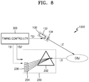
- FIG. 8 is a schematic view illustrating a Raman signal measuring apparatus 1300 according to another exemplary embodiment.
- the Raman signal measuring apparatus 1300 includes an illumination optical system 130 , a detection optical system 230 , and a timing controller 300 .
- the illumination optical system 130 includes a light source 132 and a first shutter 134 . If the timing controller 300 transmits a first timing signal TS 1 , the first shutter 134 may be operated, and light having a predetermined pulse width may be incident on a target object OBJ. If the light source 132 is a pulse laser, the first shutter 134 may be omitted, and the light source 132 may be controlled by the first timing signal TS 1 .
- the detection optical system 230 includes: a beam splitting device 232 configured to divide light LS scattered from the target object OBJ according to the wavelength of the scattered light LS; and an optical detector 236 .
- the beam splitting device 232 may be a prism.
- the beam splitting device 232 may refract incident light at different angles according to the wavelength of the incident light. For example, a relatively long wavelength may be refracted at a relatively large angle, and a relatively short wavelength may be refracted at a relatively small angle. Therefore, if scattered light LS having various wavelengths is incident on the beam splitting device 232 , the beam splitting device 232 may output the scattered light LS in different directions according to the wavelengths of the scattered light LS.
- the optical detector 236 having a plurality of pixels is positioned such that light divided by the beam splitting device 232 may strike the optical detector 236 , and thus the intensity of the light may be detected according to the wavelengths of the light, thereby obtaining a Raman spectrum.
- a second shutter 234 may be further disposed between the beam splitting device 232 and the optical detector 236 .
- the second shutter 234 may be closed according to a second timing signal TS 2 transmitted from the timing controller 300 , so as to terminate the detection of light LS scattered from the target object OBJ.
- the position of the second shutter 234 is not limited to the position shown in FIG. 8 .
- the second shutter 234 may be disposed between the beam splitting device 232 and the target object OBJ.
- the beam splitting device 232 is a prism
- the beam splitting device 232 is not limited to a prism.
- the beam splitting device 232 may be a grating device configured to split light having various wavelengths by using the property that light is diffracted by a slit at varying angles according to the wavelength of the light.
- FIG. 9 is a schematic view illustrating a Raman signal measuring apparatus 1400 according to another exemplary embodiment.
- the Raman signal measuring apparatus 1400 includes an illumination optical system 130 , a detection optical system 240 , and a timing controller 300 .
- the illumination optical system 130 includes a light source 132 and a first shutter 134 . If the timing controller 300 transmits a first timing signal TS 1 , the first shutter 134 may be operated, and light having a predetermined pulse width may be incident on a target object OBJ. If the light source 132 is a pulse laser, the first shutter 134 may be omitted, and the light source 132 may be controlled by the first timing signal TS 1 .
- the detection optical system 240 may include a linear variable filter 242 as a light splitting element, and the linear variable filter 242 may have different wavelength pass bands according to positions at which light is incident on the linear variable filter 242 .
- the linear variable filter 242 includes: two reflectors M 1 and M 2 facing each other; and a spacer SP disposed between the two reflectors M 1 and M 2 and having a gradually varying thickness. Since different wavelengths are transmitted through the spacer SP according to the thickness of the spacer SP, different light intensities may be detected from the different wavelengths by pixels of an optical detector 246 disposed near the linear variable filter 242 , and thus a Raman spectrum may be measured.
- a second shutter 244 may be further disposed between the linear variable filter 242 and the optical detector 246 .
- the second shutter 244 may be closed according to a second timing signal TS 2 transmitted from the timing controller 300 , so as to terminate the detection of light LS scattered from the target object OBJ.
- the position of the second shutter 244 is not limited to the position shown in FIG. 9 .
- the second shutter 244 may be disposed between the linear variable filter 242 and the target object OBJ.
- FIG. 10 is a schematic view illustrating a Raman signal measuring apparatus 1500 according to another exemplary embodiment.
- the detection optical system 230 or 240 is used to obtain a continuous Raman spectrum.
- the Raman signal measuring apparatus 1500 of the current exemplary embodiment includes a filter array type detection optical system 250 to selectively detect desired Raman peaks.
- the Raman signal measuring apparatus 1500 includes an illumination optical system 130 , the detection optical system 250 , and a timing controller 300 .
- the illumination optical system 130 includes a light source 132 and a first shutter 134 . If the timing controller 300 transmits a first timing signal TS 1 , the first shutter 134 may be operated, and light having a predetermined pulse width may be incident on a target object OBJ. If the light source 132 is a pulse laser, the first shutter 134 may be omitted, and the light source 132 may be controlled by the first timing signal TS 1 .
- the detection optical system 250 includes: a filter array 252 in which band pass filters having different wavelength pass bands are arranged; and an optical detector 256 .
- the wavelength pass bands of the band pass filters of the filter array 252 may be determined according to Raman peaks to be measured. Pixels of the optical detector 256 disposed near the filter array 252 may detect different light intensities in different wavelength bands, and thus a Raman spectrum may be measured.
- a second shutter 254 may be further disposed between the filter array 252 and the optical detector 256 .
- the second shutter 254 may be closed according to a second timing signal TS 2 transmitted from the timing controller 300 , so as to terminate the detection of light LS scattered from the target object OBJ.
- the position of the second shutter 254 is not limited to the position shown in FIG. 10 .
- the second shutter 254 may be disposed between the filter array 252 and the target object OBJ.
- FIG. 11 is a schematic view illustrating a Raman signal measuring apparatus 1600 according to another exemplary embodiment.
- the Raman signal measuring apparatus 1600 of the current exemplary embodiment includes a detection optical system 260 configured to selectively detect Raman peaks of interest.
- the Raman signal measuring apparatus 1600 includes an illumination optical system 130 , the detection optical system 260 , and a timing controller 300 .
- the illumination optical system 130 includes a light source 132 and a first shutter 134 . If the timing controller 300 transmits a first timing signal TS 1 , the first shutter 134 may be operated, and light having a predetermined pulse width may be incident on a target object OBJ. If the light source 132 is a pulse laser, the first shutter 134 may be omitted, and the light source 132 may be controlled by the first timing signal TS 1 .
- the detection optical system 260 includes: a plurality of dichroic filters such as a first dichroic filter 262 - 1 and a second dichroic filter 262 - 2 ; and a plurality of optical detectors such as a first optical detector 266 - 1 and a second optical detector 266 - 2 .
- Each of the dichroic filters transmits particular wavelengths of light (i.e., facilitates the propagation of the particular wavelengths of light), but reflects the other wavelengths of the light.
- the dichroic filters may include: the first dichroic filter 262 - 1 transmitting light in a first wavelength band and reflecting the light in the other wavelength bands; and the second dichroic filter 262 - 2 disposed in an optical path of the light reflected by the first dichroic filter 262 - 1 for transmitting the light in a second wavelength band and reflecting the light in the other wavelength bands.
- the number and wavelength pass bands of the dichroic filters may be determined according to Raman peaks of interest.
- a plurality of band pass filters having different wavelength pass bands may be further disposed between the dichroic filters and the optical detectors.
- a plurality of second shutters such as second shutters 264 - 1 and 264 - 2 , may be further disposed between the band pass filters and the optical detectors.
- the second shutters 264 - 1 and 264 - 2 may be closed according to a second timing signal TS 2 transmitted from the timing controller 300 , so as to terminate the detection of light LS scattered from the target object OBJ.
- the positions of the second shutters 264 - 1 and 264 - 2 are not limited to the positions shown in FIG. 11 .
- the second filters 264 - 1 and 264 - 2 may be disposed between the dichroic filters 262 - 1 , 262 - 2 and the band pass filters 263 - 1 , 263 - 2 .
- only one second shutter may be disposed between the target object OBJ and the first dichroic filter 262 - 1 .
- the Raman signal measuring apparatuses 1300 , 1400 , 1500 , and 1600 respectively described above with reference to FIGS. 8, 9, 10, and 11 include the illumination optical systems 130 and the detection optical systems 230 , 240 , 250 , and 260 .
- the Raman signal measuring apparatuses 1300 , 1400 , 1500 , and 1600 may further include various optical elements configured to direct or guide light from the illumination optical systems 130 to target objects OBJ and direct or guide scattered light LS from the target objects OBJ to the detection optical systems 230 , 240 , 250 , and 260 .
- each of the illumination optical systems 130 may further include an element such as any of an aperture stop, an optical path changer, a collimating lens, a relay lens, and/or an object lens.
- each of the detection optical systems 230 , 240 , 250 , and 260 may include an element such as any of an aperture stop, a collimating lens, and/or an object lens.
- FIG. 12 is a block diagram illustrating a biometric information analyzing apparatus 2000 according to an exemplary embodiment.
- the biometric information analyzing apparatus 2000 may be used for measuring and analyzing biological substances or the composition of living organisms in a non-invasive method.
- the biometric information analyzing apparatus 2000 includes: an illumination optical system 100 including a light source configured to emit exciting light to a target object OBJ; a detection optical system 200 including an optical detector configured to detect light LS scattered from the target object OBJ; a timing controller 300 configured to control an operation timing of each of the illumination optical system 100 and the detection optical system 200 ; and a signal processor 500 configured to analyze properties of the target object OBJ using signals output from the detection optical system 200 .
- the biometric information analyzing apparatus 2000 may further include: an amplifier 400 configured to amplify signals detected by the detection optical system 200 ; a user interface 600 configured to provide analysis results of the signal processor 500 to users; and/or a memory 700 that stores programs and data necessary for operations of the signal processor 500 .
- the biometric information analyzing apparatus 2000 of the current exemplary embodiment uses one of the above-described Raman signal measuring apparatuses 1100 , 1200 , 1300 , 1400 , 1500 , and 1600 .
- the biometric information analyzing apparatus 2000 may employ the configuration of the illumination optical system 110 , 120 , or 130 and the configuration of the detection optical system 210 , 220 , 230 , 240 , 250 , or 260 .
- the light source of the illumination optical system 100 may rapidly operate before fluorescence is generated from the target object OBJ.
- the light source may provide pulsed light.
- the light source may include a continuous wave laser and a chopper, or may include a mode-locking pulse laser, so as provide pulsed light.
- the pulse width of the pulsed light may be shorter than a time period required until fluorescence is generated from the target object OBJ.
- the detection optical system 200 includes a light splitting element and the optical detector.
- the detection optical system 200 may further include a shutter, and the shutter may be operated under the control of the timing controller 300 to prevent light LS scattered from the target object OBJ from reaching the optical detector.
- the optical detector may be a high-speed optical detector having a light detection response time shorter than a time period required until fluorescence is generated from the target object OBJ.
- the optical detector may have a light detection response time within the range of about 1 nanosecond to about 2 nanoseconds.
- the illumination optical system 100 and the detection optical system 200 may enter a lock-in state under the control of the timing controller 300 .
- the timing controller 300 may include a local oscillator capable of generating waves in a gigahertz (GHz) or higher frequency band, so as to generate a proper timing signal.
- GHz gigahertz
- the timing controller 300 may generate a timing signal so as to terminate the detection of light by the detection optical system 200 before fluorescence is generated from the target object OBJ in response to exciting light LE emitted from the illumination optical system 100 .
- the timing controller 300 may transmit a first timing signal TS 1 to the illumination optical system 100 , and the illumination optical system 100 may emit exciting light LE to the target object OBJ according to the first timing signal TS 1 .
- the timing controller 300 may transmit the first timing signal TS 1 to the detection optical system 200 .
- the detection optical system 200 may detect light LS scattered from the target object OBJ according to the first timing signal TS 1 received from the timing controller 300 .
- this is an example.
- the timing controller 300 transmits the first timing signal TS 1 to the detection optical system 200 .
- the detection optical system 200 may wait in detection mode, and if exciting light LE is emitted to the target object OBJ according to the first timing signal TS 1 , the detection optical system 200 may detect light LS scattered from the target object OBJ.
- the timing controller 300 may transmit a second timing signal TS 2 to the detection optical system 200 .
- the second timing signal TS 2 is transmitted to the detection optical system 200 before the elapse of a time period t FL required until fluorescence is generated from the target object OBJ in response to exciting light LE. That is, a time difference ⁇ t between the second timing signal TS 2 and the first timing signal TS 1 is shorter than the time period t FL taken for the target object OBJ to generate fluorescence.
- the detection of light by the detection optical system 200 may be terminated according to the second timing signal TS 2 .
- the signal processor 500 analyzes properties of the target object OBJ using signals output from the detection optical system 200 .
- the signal processor 500 may analyze substances included in tissue or blood of the target object OBJ and/or the composition of the target object OBJ.
- the properties of the target object OBJ may be analyzed by a Raman analysis method.
- the Raman analysis method uses such energy state shifts.
- Exciting light LE emitted from the illumination optical system 100 to the target object OBJ is scattered from molecular structures of the target object OBJ, and the scattered light LS may have wavelengths shifted from the wavelength of the exciting light LE.
- the scattered light LS that is, a biological optical signal, may have various spectrums because the degree of wavelength shift of the scattered light LS is varied according to the molecular state of the target object OBJ.
- a detected Raman signal includes information about wavelengths shifted from the wavelength of incident light, and such wavelength shifts are energy shifts including information about molecular vibrations of substances such as information about molecular structures, molecular bonds, or functional groups.
- Raman peaks appear in a Raman spectrum according to the molecular composition of the target object OBJ.
- substances such as glucose, urea, ceramides, keratin, or collagen may be included in intercellular fluids or blood of the target object OBJ.
- glucose may exhibit Raman shifts of about 436.4 cm ⁇ 1 , about 1065 cm ⁇ 1 , about 1126.4 cm ⁇ 1 , and about 525.7 cm ⁇ 1 in wavenumber.
- Collagen may exhibit Raman shifts of about 855 cm ⁇ 1 and about 936 cm ⁇ 1 in wavenumber.
- Urea may exhibit a Raman shift of about 1000 cm ⁇ 1 in wavenumber.
- the signal processor 500 may analyze the distribution amounts of substances from the intensity of spectrum peaks appearing because the wavelength of exciting light LE is Raman-shifted by the substances. For example, if the intensity of spectrum peaks is high at positions indicating that the frequency of incident light is shifted by about 436.4 cm ⁇ 1 , about 1065 cm ⁇ 1 , about 1126.4 cm ⁇ 1 , and about 525.7 cm ⁇ 1 in wavenumber, the distribution amount of glucose may be large. In addition, if the intensity of spectrum peaks is high at positions indicating that the frequency of incident light is shifted by about 855 cm ⁇ 1 and about 936 cm ⁇ 1 in wavenumber, the distribution amount of collagen may be large.
- the signal processor 500 may analyze the distribution amounts of substances included in the skin of the target object OBJ and may check the health state of the target object OBJ. As described above, since a Raman signal is obtained before fluorescence is generated from the target object OBJ, background fluorescence may not be included in the Raman signal, and thus the accuracy of measurement and diagnosis may be improved.
- the signal processor 500 may generate control signals so as to control the overall operation of the biometric information analyzing apparatus 2000 .
- the signal processor 500 may convert analysis results into image signals so as to display the image signals on a display of the user interface 600 .
- the signal processor 500 may transmit a control signal to the timing controller 300 in response to a signal input through the user interface 600 .
- the signal processor 500 may include a device such as a microprocessor.
- the user interface 600 may be an interface connecting the biometric information analyzing apparatus 2000 to users and/or interfaces of other external devices.
- the user interface 600 may include an input unit and the display.
- Programs necessary for operations of the signal processor 500 may be stored in the memory 700 , and input/output data may be stored in the memory 700 .
- the memory 700 may store a lookup table providing a relationship between spectrum peaks and amounts of substances, and thus the amounts of substances may be determined from the intensity of Raman spectrum peaks by using the lookup table.
- the memory 700 may include a recording medium such as a flash memory, a hard disk, a micro multimedia card, a memory card including a secure digital (SD) card or an extreme digital (XD) card, a random access memory (RAM) a static random access memory (SRAM), a read-only memory (ROM), an electrically erasable programmable read-only memory (EEPROM), a programmable read-only memory (PROM), a magnetic memory, a magnetic disk, or an optical disk.
- a recording medium such as a flash memory, a hard disk, a micro multimedia card, a memory card including a secure digital (SD) card or an extreme digital (XD) card, a random access memory (RAM) a static random access memory (SRAM), a read-only memory (ROM), an electrically erasable programmable read-only memory (EEPROM), a programmable read-only memory (PROM), a magnetic memory, a magnetic disk, or an optical disk.
- SD secure digital
- XD extreme
- the biometric information analyzing apparatus 2000 may further include a communication unit (also referred to herein as a “communicator”) that includes a transmitter and a receiver or a transceiver.
- a communication unit also referred to herein as a “communicator”
- analysis results may be transmitted to an external device through the communication unit.
- the external device may be a medical device using analyzed biological information, a printer for printing the analysis results, or a display for displaying the analysis results.
- the external device may be a smartphone, a cellular phone, a personal digital assistant (PDA), a laptop personal computer (PC), a mobile device, or a mobile computing device.
- PDA personal digital assistant
- PC personal computer
- the external device is not limited to the listed devices.
- the Raman signal measuring method and apparatus enables the detection of a Raman signal from a target object while minimizing the amount of background fluorescence in the Raman signal. Therefore, additional optical members or processes may not be used or performed to separate Raman peaks from background fluorescence, and the accuracy and repeatability of measurement may be improved.
- the biometric information analyzing apparatus is a non-invasive analyzing apparatus using a Raman analysis method. Since Raman signals having fewer errors are obtainable using the biometric information analyzing apparatus, biological data may be more precisely analyzed for accurate diagnosis.
- the apparatuses of the exemplary embodiments may include a processor, a memory storing and executing program data, a permanent storage such as a disk drive, a communication port for communication with an external device, a user interface device such as a touch panel, keys or buttons, and the like.
- Methods embodied as a software module or an algorithm may be stored on a transitory or non-transitory computer-readable recording medium as computer readable codes or program commands executable by the processor. Examples of a non-transitory computer-readable recording medium include magnetic storage media (e.g., ROM, floppy disks, hard disks, etc.), optical recording media (e.g., CD-ROMs, or DVDs), and the like.
- the computer-readable recording medium can also be distributed over network-coupled computer systems so that the computer readable code is stored and executed in a distributed fashion. The medium can be read by a computer, stored in a memory, and executed by the processor.
- the inventive concept of the present disclosure may be embodied as functional blocks and various processing operations.
- the functional blocks may be implemented with various hardware and/or software configurations executing specific functions.
- exemplary embodiments of the present disclosure may employ integrated circuit configurations such as a memory, processing, logic, a look-up table and the like capable of executing various functions upon control of microprocessors or other control devices.
- the exemplary embodiments may be implemented with a scripting language or a programming language such as C, C++, Java, assembler, and the like, including various algorithms implemented by a combination of data structures, processes, routines or other programming configurations.
- the functional aspects may be implemented by algorithms executed in one or more processors. Also, the exemplary embodiments may employ conversional arts to establish an electronic environment, process signals, and/or process data. Terms such as “mechanism,” “element,” “means,” and “configuration” may be widely used and are not limited to mechanical and physical configurations. Such terms may have the meaning of a series of routines of software in association with a processor or the like.
Landscapes
- Physics & Mathematics (AREA)
- Spectroscopy & Molecular Physics (AREA)
- General Physics & Mathematics (AREA)
- Health & Medical Sciences (AREA)
- Life Sciences & Earth Sciences (AREA)
- General Health & Medical Sciences (AREA)
- Pathology (AREA)
- Engineering & Computer Science (AREA)
- Biomedical Technology (AREA)
- Molecular Biology (AREA)
- Heart & Thoracic Surgery (AREA)
- Medical Informatics (AREA)
- Surgery (AREA)
- Animal Behavior & Ethology (AREA)
- Biophysics (AREA)
- Public Health (AREA)
- Veterinary Medicine (AREA)
- Chemical & Material Sciences (AREA)
- Nuclear Medicine, Radiotherapy & Molecular Imaging (AREA)
- Analytical Chemistry (AREA)
- Biochemistry (AREA)
- Immunology (AREA)
- Artificial Intelligence (AREA)
- Computer Vision & Pattern Recognition (AREA)
- Physiology (AREA)
- Psychiatry (AREA)
- Signal Processing (AREA)
- Investigating, Analyzing Materials By Fluorescence Or Luminescence (AREA)
- Emergency Medicine (AREA)
- Optics & Photonics (AREA)
Applications Claiming Priority (2)
| Application Number | Priority Date | Filing Date | Title |
|---|---|---|---|
| KR10-2015-0161054 | 2015-11-17 | ||
| KR1020150161054A KR102444284B1 (ko) | 2015-11-17 | 2015-11-17 | 라만 신호 측정 방법, 장치 및 라만 신호 측정 장치를 포함하는 생체 정보 분석 장치 |
Publications (2)
| Publication Number | Publication Date |
|---|---|
| US20170135582A1 US20170135582A1 (en) | 2017-05-18 |
| US10874301B2 true US10874301B2 (en) | 2020-12-29 |
Family
ID=57288269
Family Applications (1)
| Application Number | Title | Priority Date | Filing Date |
|---|---|---|---|
| US15/353,198 Active 2039-10-25 US10874301B2 (en) | 2015-11-17 | 2016-11-16 | Raman signal measuring method and apparatus, and biometric information analyzing apparatus including the Raman signal measuring apparatus |
Country Status (3)
| Country | Link |
|---|---|
| US (1) | US10874301B2 (fr) |
| EP (1) | EP3171162B1 (fr) |
| KR (1) | KR102444284B1 (fr) |
Families Citing this family (7)
| Publication number | Priority date | Publication date | Assignee | Title |
|---|---|---|---|---|
| TWI592646B (zh) * | 2015-12-23 | 2017-07-21 | 高準精密工業股份有限公司 | 光學裝置 |
| US10859499B2 (en) * | 2017-05-22 | 2020-12-08 | Samsung Electronics Co., Ltd. | Apparatus and method for quantitative molecular sensing based on raman peak shift |
| KR102634937B1 (ko) * | 2017-12-08 | 2024-02-07 | 삼성전자주식회사 | 빛샘 도파관, 분광 방법 및 빛샘 도파관을 포함하는 분광기 |
| CN109856118A (zh) * | 2019-04-15 | 2019-06-07 | 中国计量大学 | 一种新型拉曼光谱中荧光抑制的装置及其方法 |
| DE102019112346A1 (de) * | 2019-05-10 | 2020-11-12 | TRUMPF Venture GmbH | System zur Messung des Vorhandenseins und/oder der Konzentration einer in Körperflüssigkeit gelösten Analysesubstanz |
| KR102273485B1 (ko) * | 2019-12-05 | 2021-07-06 | 주식회사 신코 | 멀티형 형광측정기 |
| KR102640751B1 (ko) * | 2021-11-24 | 2024-02-27 | 주식회사 에스에스솔루션 | 다이크로익 필터를 이용한 유해물질 혼합가스의 검출 장치 |
Citations (13)
| Publication number | Priority date | Publication date | Assignee | Title |
|---|---|---|---|---|
| JPH10148573A (ja) | 1996-11-19 | 1998-06-02 | Rikagaku Kenkyusho | 分光分析法及び分光分析装置 |
| US5946090A (en) | 1996-11-19 | 1999-08-31 | The Institute Of Physical And Chemical Research | Spectrometric method and apparatus for spectrometry |
| US20060188869A1 (en) * | 2005-01-13 | 2006-08-24 | Whitehead Institute For Biomedical Research | Method and apparatus for UV imaging |
| US20070060806A1 (en) | 2005-04-27 | 2007-03-15 | Martin Hunter | Raman spectroscopy for non-invasive glucose measurements |
| US20070222982A1 (en) | 2006-03-24 | 2007-09-27 | David Tuschel | System and method to perform raman imaging without luminescence |
| KR20110133778A (ko) | 2010-06-07 | 2011-12-14 | 한국과학기술원 | 광전자유체제어 면역분석장치 및 방법 |
| US20120212812A1 (en) * | 2009-11-17 | 2012-08-23 | 3M Innovative Properties Company | Polarization sensitive front projection screen |
| KR20120132668A (ko) | 2011-05-29 | 2012-12-07 | 한국화학연구원 | 라만 분석 기반 고속 다중 약물 고속 스크리닝 장치 |
| US20140226158A1 (en) * | 2004-03-06 | 2014-08-14 | Michael Trainer | Methods and apparatus for determining particle characteristics |
| WO2014125171A1 (fr) | 2013-02-15 | 2014-08-21 | Oulun Yliopisto | Mesure du rayonnement raman |
| US20160202178A1 (en) * | 2015-01-12 | 2016-07-14 | Verily Life Sciences Llc | High-Throughput Hyperspectral Imaging With Superior Resolution And Optical Sectioning |
| US20180280723A1 (en) * | 2016-05-26 | 2018-10-04 | San Diego State University Research Foundation | Photoeradication of microorganisms with pulsed purple or blue light |
| US20190374092A1 (en) * | 2017-01-12 | 2019-12-12 | Canon U.S.A., Inc. | Spectrally Encoded Forward View Endoscope and Spectrally Encoded Multi-View Endoscope, Probe, and Imaging Apparatus |
Family Cites Families (2)
| Publication number | Priority date | Publication date | Assignee | Title |
|---|---|---|---|---|
| JP2002005835A (ja) * | 2000-06-23 | 2002-01-09 | 宏夫 ▲浜▼口 | ラマン分光測定装置及びそれを用いた生体試料分析方法 |
| JP2015175846A (ja) * | 2014-11-06 | 2015-10-05 | キヤノン株式会社 | ラマン散乱計測装置 |
-
2015
- 2015-11-17 KR KR1020150161054A patent/KR102444284B1/ko active IP Right Grant
-
2016
- 2016-11-14 EP EP16198556.9A patent/EP3171162B1/fr active Active
- 2016-11-16 US US15/353,198 patent/US10874301B2/en active Active
Patent Citations (14)
| Publication number | Priority date | Publication date | Assignee | Title |
|---|---|---|---|---|
| US5946090A (en) | 1996-11-19 | 1999-08-31 | The Institute Of Physical And Chemical Research | Spectrometric method and apparatus for spectrometry |
| JPH10148573A (ja) | 1996-11-19 | 1998-06-02 | Rikagaku Kenkyusho | 分光分析法及び分光分析装置 |
| US20140226158A1 (en) * | 2004-03-06 | 2014-08-14 | Michael Trainer | Methods and apparatus for determining particle characteristics |
| US20060188869A1 (en) * | 2005-01-13 | 2006-08-24 | Whitehead Institute For Biomedical Research | Method and apparatus for UV imaging |
| US20070060806A1 (en) | 2005-04-27 | 2007-03-15 | Martin Hunter | Raman spectroscopy for non-invasive glucose measurements |
| US20070222982A1 (en) | 2006-03-24 | 2007-09-27 | David Tuschel | System and method to perform raman imaging without luminescence |
| US20120212812A1 (en) * | 2009-11-17 | 2012-08-23 | 3M Innovative Properties Company | Polarization sensitive front projection screen |
| KR20110133778A (ko) | 2010-06-07 | 2011-12-14 | 한국과학기술원 | 광전자유체제어 면역분석장치 및 방법 |
| KR20120132668A (ko) | 2011-05-29 | 2012-12-07 | 한국화학연구원 | 라만 분석 기반 고속 다중 약물 고속 스크리닝 장치 |
| US20140113283A1 (en) | 2011-05-29 | 2014-04-24 | Korea Research Institute Of Chemical Technology | High-speed screening apparatus for a raman analysis-based high-speed multiple drug |
| WO2014125171A1 (fr) | 2013-02-15 | 2014-08-21 | Oulun Yliopisto | Mesure du rayonnement raman |
| US20160202178A1 (en) * | 2015-01-12 | 2016-07-14 | Verily Life Sciences Llc | High-Throughput Hyperspectral Imaging With Superior Resolution And Optical Sectioning |
| US20180280723A1 (en) * | 2016-05-26 | 2018-10-04 | San Diego State University Research Foundation | Photoeradication of microorganisms with pulsed purple or blue light |
| US20190374092A1 (en) * | 2017-01-12 | 2019-12-12 | Canon U.S.A., Inc. | Spectrally Encoded Forward View Endoscope and Spectrally Encoded Multi-View Endoscope, Probe, and Imaging Apparatus |
Non-Patent Citations (3)
| Title |
|---|
| Communication dated Apr. 20, 2017, from the European Patent Office in counterpart European Application No. 16198556.9. |
| MATOUSEK P., ET AL.: "EFFICIENT REJECTION OF FLUORESCENCE FROM RAMAN SPECTRA USING PICOSECOND KERR GATING.", APPLIED SPECTROSCOPY., THE SOCIETY FOR APPLIED SPECTROSCOPY. BALTIMORE., US, vol. 53., no. 12., 1 December 1999 (1999-12-01), US, pages 1485 - 1489., XP000903126, ISSN: 0003-7028, DOI: 10.1366/0003702991945993 |
| P. Matousek et al., "Efficient Rejection of Fluorescence from Raman Spectra Using Picosecond Kerr Gating", Applied Spectroscopy, Society for Applied Spectroscopy, vol. 53, No. 12, 1999, pp. 1485-1489, XP-000903126. |
Also Published As
| Publication number | Publication date |
|---|---|
| EP3171162A1 (fr) | 2017-05-24 |
| EP3171162B1 (fr) | 2021-04-28 |
| KR20170057672A (ko) | 2017-05-25 |
| KR102444284B1 (ko) | 2022-09-16 |
| US20170135582A1 (en) | 2017-05-18 |
Similar Documents
| Publication | Publication Date | Title |
|---|---|---|
| US10874301B2 (en) | Raman signal measuring method and apparatus, and biometric information analyzing apparatus including the Raman signal measuring apparatus | |
| AU2021282521B2 (en) | Diagnostic method using laser induced breakdown spectroscopy, and diagnostic device for performing same | |
| US10352849B2 (en) | Terahertz time domain spectroscopic apparatus | |
| AU2009200825B2 (en) | Dual pulse single event raman spectroscopy | |
| JP6560983B2 (ja) | ガス分析装置およびガス分析方法 | |
| CN105699317A (zh) | 固定角度入射同时测透射和反射的太赫兹时域光谱仪 | |
| CN106769971A (zh) | 一种基于飞秒泵浦探测的红外光谱系统 | |
| US9874474B2 (en) | Biometric sensor and biometric analysis system including the same | |
| JP2019502125A (ja) | 電子励起状態の平均寿命時間を測定するための発光寿命時間測定方法及び装置 | |
| US11221271B2 (en) | Photoacoustic sensor for detecting trace amounts of hydrocarbons in gases or liquids | |
| WO2016006211A1 (fr) | Dispositif de mesure d'informations d'élément biologique | |
| KR20190100695A (ko) | 라만 프로브 및 이를 이용한 생체 성분 분석 장치 | |
| Bengtsson et al. | Characterization and modeling of acousto-optic signal strengths in highly scattering media | |
| KR102477678B1 (ko) | 액체 중의 ndir 글루코스 검출 | |
| JP2004527767A (ja) | 濃縮媒質に含まれる化学種の光学検出方法 | |
| US20210341380A1 (en) | Flow cytometers including laser assessors, and methods for using the same | |
| JP2016145722A (ja) | 異物検出装置 | |
| RU2429454C1 (ru) | Спектрометр когерентного антистоксова рассеяния с контролем спектра широкополосной накачки | |
| JP2022536890A (ja) | 無線周波数多重信号の位相補正 | |
| JP2023106835A (ja) | 過渡吸収測定装置、および、測定方法 | |
| JP2013205339A (ja) | 全反射吸収測定装置および全反射吸収測定方法 | |
| CN111103256A (zh) | 一种光谱检测装置和光谱检测方法 | |
| Adam | Optoelectronic Sensor of NO 2 Detection using Cavity Ring Down Spectroscopy and 414 nm GaN Diode Laser | |
| JPWO2018066361A1 (ja) | 検査装置、検査方法、コンピュータプログラム及び記録媒体 | |
| Pellegrino et al. | Spectroscopic Techniques for Proximal Hazard Detection |
Legal Events
| Date | Code | Title | Description |
|---|---|---|---|
| AS | Assignment |
Owner name: MASSACHUSETTS INSTITUTE OF TECHNOLOGY, MASSACHUSET Free format text: ASSIGNMENT OF ASSIGNORS INTEREST;ASSIGNORS:CHO, SEONGHO;SINGH, GAJENDRA;LEE, JUNEYOUNG;SIGNING DATES FROM 20160521 TO 20160525;REEL/FRAME:040345/0929 Owner name: SAMSUNG ELECTRONICS CO., LTD., KOREA, REPUBLIC OF Free format text: ASSIGNMENT OF ASSIGNORS INTEREST;ASSIGNORS:CHO, SEONGHO;SINGH, GAJENDRA;LEE, JUNEYOUNG;SIGNING DATES FROM 20160521 TO 20160525;REEL/FRAME:040345/0929 Owner name: MASSACHUSETTS INSTITUTE OF TECHNOLOGY, MASSACHUSETTS Free format text: ASSIGNMENT OF ASSIGNORS INTEREST;ASSIGNORS:CHO, SEONGHO;SINGH, GAJENDRA;LEE, JUNEYOUNG;SIGNING DATES FROM 20160521 TO 20160525;REEL/FRAME:040345/0929 |
|
| STPP | Information on status: patent application and granting procedure in general |
Free format text: DOCKETED NEW CASE - READY FOR EXAMINATION |
|
| STPP | Information on status: patent application and granting procedure in general |
Free format text: NON FINAL ACTION MAILED |
|
| STPP | Information on status: patent application and granting procedure in general |
Free format text: RESPONSE TO NON-FINAL OFFICE ACTION ENTERED AND FORWARDED TO EXAMINER |
|
| STPP | Information on status: patent application and granting procedure in general |
Free format text: NOTICE OF ALLOWANCE MAILED -- APPLICATION RECEIVED IN OFFICE OF PUBLICATIONS |
|
| STPP | Information on status: patent application and granting procedure in general |
Free format text: PUBLICATIONS -- ISSUE FEE PAYMENT VERIFIED |
|
| STCF | Information on status: patent grant |
Free format text: PATENTED CASE |