US10835729B2 - Hemostasis valve design for introducer sheath - Google Patents
Hemostasis valve design for introducer sheath Download PDFInfo
- Publication number
- US10835729B2 US10835729B2 US15/806,315 US201715806315A US10835729B2 US 10835729 B2 US10835729 B2 US 10835729B2 US 201715806315 A US201715806315 A US 201715806315A US 10835729 B2 US10835729 B2 US 10835729B2
- Authority
- US
- United States
- Prior art keywords
- central region
- hemostasis valve
- proximal
- slits
- valve
- Prior art date
- Legal status (The legal status is an assumption and is not a legal conclusion. Google has not performed a legal analysis and makes no representation as to the accuracy of the status listed.)
- Active, expires
Links
- 230000023597 hemostasis Effects 0.000 title claims abstract description 115
- 238000013461 design Methods 0.000 title description 3
- 229920002379 silicone rubber Polymers 0.000 claims description 21
- 239000004944 Liquid Silicone Rubber Substances 0.000 claims description 14
- 229920001296 polysiloxane Polymers 0.000 claims description 9
- 230000007423 decrease Effects 0.000 claims description 3
- 229910001000 nickel titanium Inorganic materials 0.000 description 24
- 239000000463 material Substances 0.000 description 19
- HLXZNVUGXRDIFK-UHFFFAOYSA-N nickel titanium Chemical compound [Ti].[Ti].[Ti].[Ti].[Ti].[Ti].[Ti].[Ti].[Ti].[Ti].[Ti].[Ni].[Ni].[Ni].[Ni].[Ni].[Ni].[Ni].[Ni].[Ni].[Ni].[Ni].[Ni].[Ni].[Ni] HLXZNVUGXRDIFK-UHFFFAOYSA-N 0.000 description 16
- -1 polytetrafluoroethylene Polymers 0.000 description 11
- 229910001182 Mo alloy Inorganic materials 0.000 description 7
- 238000000576 coating method Methods 0.000 description 7
- 230000002792 vascular Effects 0.000 description 7
- 229910045601 alloy Inorganic materials 0.000 description 6
- 239000000956 alloy Substances 0.000 description 6
- 238000000034 method Methods 0.000 description 6
- 229920000642 polymer Polymers 0.000 description 6
- PXHVJJICTQNCMI-UHFFFAOYSA-N Nickel Chemical compound [Ni] PXHVJJICTQNCMI-UHFFFAOYSA-N 0.000 description 4
- 239000011248 coating agent Substances 0.000 description 4
- 229910000856 hastalloy Inorganic materials 0.000 description 4
- 230000013011 mating Effects 0.000 description 4
- 239000000203 mixture Substances 0.000 description 4
- BASFCYQUMIYNBI-UHFFFAOYSA-N platinum Chemical compound [Pt] BASFCYQUMIYNBI-UHFFFAOYSA-N 0.000 description 4
- 229920001343 polytetrafluoroethylene Polymers 0.000 description 4
- 239000004810 polytetrafluoroethylene Substances 0.000 description 4
- 239000010935 stainless steel Substances 0.000 description 4
- 229910001220 stainless steel Inorganic materials 0.000 description 4
- RTZKZFJDLAIYFH-UHFFFAOYSA-N Diethyl ether Chemical compound CCOCC RTZKZFJDLAIYFH-UHFFFAOYSA-N 0.000 description 3
- 239000004952 Polyamide Substances 0.000 description 3
- 229920002614 Polyether block amide Polymers 0.000 description 3
- 239000004721 Polyphenylene oxide Substances 0.000 description 3
- 238000001125 extrusion Methods 0.000 description 3
- 229920001903 high density polyethylene Polymers 0.000 description 3
- 239000004700 high-density polyethylene Substances 0.000 description 3
- 238000002595 magnetic resonance imaging Methods 0.000 description 3
- 238000004519 manufacturing process Methods 0.000 description 3
- 229910052751 metal Inorganic materials 0.000 description 3
- 239000002184 metal Substances 0.000 description 3
- 229920002647 polyamide Polymers 0.000 description 3
- 230000000153 supplemental effect Effects 0.000 description 3
- 229910000881 Cu alloy Inorganic materials 0.000 description 2
- 239000004812 Fluorinated ethylene propylene Substances 0.000 description 2
- 229920000339 Marlex Polymers 0.000 description 2
- KDLHZDBZIXYQEI-UHFFFAOYSA-N Palladium Chemical compound [Pd] KDLHZDBZIXYQEI-UHFFFAOYSA-N 0.000 description 2
- 239000004696 Poly ether ether ketone Substances 0.000 description 2
- 239000004697 Polyetherimide Substances 0.000 description 2
- 239000004698 Polyethylene Substances 0.000 description 2
- 239000004642 Polyimide Substances 0.000 description 2
- 239000004734 Polyphenylene sulfide Substances 0.000 description 2
- 239000004743 Polypropylene Substances 0.000 description 2
- RTAQQCXQSZGOHL-UHFFFAOYSA-N Titanium Chemical compound [Ti] RTAQQCXQSZGOHL-UHFFFAOYSA-N 0.000 description 2
- 229910001080 W alloy Inorganic materials 0.000 description 2
- MTHLBYMFGWSRME-UHFFFAOYSA-N [Cr].[Co].[Mo] Chemical compound [Cr].[Co].[Mo] MTHLBYMFGWSRME-UHFFFAOYSA-N 0.000 description 2
- 238000004458 analytical method Methods 0.000 description 2
- 229910001566 austenite Inorganic materials 0.000 description 2
- 238000005452 bending Methods 0.000 description 2
- 230000008901 benefit Effects 0.000 description 2
- 239000008280 blood Substances 0.000 description 2
- 210000004369 blood Anatomy 0.000 description 2
- 239000000788 chromium alloy Substances 0.000 description 2
- PRQRQKBNBXPISG-UHFFFAOYSA-N chromium cobalt molybdenum nickel Chemical compound [Cr].[Co].[Ni].[Mo] PRQRQKBNBXPISG-UHFFFAOYSA-N 0.000 description 2
- 238000007796 conventional method Methods 0.000 description 2
- 229920001577 copolymer Polymers 0.000 description 2
- YOCUPQPZWBBYIX-UHFFFAOYSA-N copper nickel Chemical compound [Ni].[Cu] YOCUPQPZWBBYIX-UHFFFAOYSA-N 0.000 description 2
- 238000000113 differential scanning calorimetry Methods 0.000 description 2
- 229920001971 elastomer Polymers 0.000 description 2
- 239000000806 elastomer Substances 0.000 description 2
- 229910000701 elgiloys (Co-Cr-Ni Alloy) Inorganic materials 0.000 description 2
- 150000002148 esters Chemical class 0.000 description 2
- 229920000840 ethylene tetrafluoroethylene copolymer Polymers 0.000 description 2
- 239000000945 filler Substances 0.000 description 2
- 229920001477 hydrophilic polymer Polymers 0.000 description 2
- 229910000734 martensite Inorganic materials 0.000 description 2
- 230000007246 mechanism Effects 0.000 description 2
- 229910001092 metal group alloy Inorganic materials 0.000 description 2
- 238000012986 modification Methods 0.000 description 2
- 230000004048 modification Effects 0.000 description 2
- DDTIGTPWGISMKL-UHFFFAOYSA-N molybdenum nickel Chemical compound [Ni].[Mo] DDTIGTPWGISMKL-UHFFFAOYSA-N 0.000 description 2
- 229910052759 nickel Inorganic materials 0.000 description 2
- 229920009441 perflouroethylene propylene Polymers 0.000 description 2
- 229910052697 platinum Inorganic materials 0.000 description 2
- 229920001200 poly(ethylene-vinyl acetate) Polymers 0.000 description 2
- 229920001707 polybutylene terephthalate Polymers 0.000 description 2
- 229920000728 polyester Polymers 0.000 description 2
- 229920002530 polyetherether ketone Polymers 0.000 description 2
- 229920001601 polyetherimide Polymers 0.000 description 2
- 229920000573 polyethylene Polymers 0.000 description 2
- 229920000139 polyethylene terephthalate Polymers 0.000 description 2
- 239000005020 polyethylene terephthalate Substances 0.000 description 2
- 229920001721 polyimide Polymers 0.000 description 2
- 229920006324 polyoxymethylene Polymers 0.000 description 2
- 229920006380 polyphenylene oxide Polymers 0.000 description 2
- 229920000069 polyphenylene sulfide Polymers 0.000 description 2
- 229920001155 polypropylene Polymers 0.000 description 2
- 229920002635 polyurethane Polymers 0.000 description 2
- 239000004814 polyurethane Substances 0.000 description 2
- 230000009467 reduction Effects 0.000 description 2
- 239000010936 titanium Substances 0.000 description 2
- 229910052719 titanium Inorganic materials 0.000 description 2
- KHXKESCWFMPTFT-UHFFFAOYSA-N 1,1,1,2,2,3,3-heptafluoro-3-(1,2,2-trifluoroethenoxy)propane Chemical compound FC(F)=C(F)OC(F)(F)C(F)(F)C(F)(F)F KHXKESCWFMPTFT-UHFFFAOYSA-N 0.000 description 1
- 229910000531 Co alloy Inorganic materials 0.000 description 1
- 229920004943 Delrin® Polymers 0.000 description 1
- 229920006055 Durethan® Polymers 0.000 description 1
- 239000004593 Epoxy Substances 0.000 description 1
- 229920000219 Ethylene vinyl alcohol Polymers 0.000 description 1
- 229910000640 Fe alloy Inorganic materials 0.000 description 1
- 229920003620 Grilon® Polymers 0.000 description 1
- DGAQECJNVWCQMB-PUAWFVPOSA-M Ilexoside XXIX Chemical compound C[C@@H]1CC[C@@]2(CC[C@@]3(C(=CC[C@H]4[C@]3(CC[C@@H]5[C@@]4(CC[C@@H](C5(C)C)OS(=O)(=O)[O-])C)C)[C@@H]2[C@]1(C)O)C)C(=O)O[C@H]6[C@@H]([C@H]([C@@H]([C@H](O6)CO)O)O)O.[Na+] DGAQECJNVWCQMB-PUAWFVPOSA-M 0.000 description 1
- 229920000271 Kevlar® Polymers 0.000 description 1
- JHWNWJKBPDFINM-UHFFFAOYSA-N Laurolactam Chemical compound O=C1CCCCCCCCCCCN1 JHWNWJKBPDFINM-UHFFFAOYSA-N 0.000 description 1
- 229910001209 Low-carbon steel Inorganic materials 0.000 description 1
- 229910000792 Monel Inorganic materials 0.000 description 1
- 229910000990 Ni alloy Inorganic materials 0.000 description 1
- 239000004677 Nylon Substances 0.000 description 1
- 229920000299 Nylon 12 Polymers 0.000 description 1
- 229930040373 Paraformaldehyde Natural products 0.000 description 1
- 229920000265 Polyparaphenylene Polymers 0.000 description 1
- 239000004793 Polystyrene Substances 0.000 description 1
- QXZUUHYBWMWJHK-UHFFFAOYSA-N [Co].[Ni] Chemical compound [Co].[Ni] QXZUUHYBWMWJHK-UHFFFAOYSA-N 0.000 description 1
- HZEWFHLRYVTOIW-UHFFFAOYSA-N [Ti].[Ni] Chemical compound [Ti].[Ni] HZEWFHLRYVTOIW-UHFFFAOYSA-N 0.000 description 1
- 229920000615 alginic acid Polymers 0.000 description 1
- 235000010443 alginic acid Nutrition 0.000 description 1
- 229920000249 biocompatible polymer Polymers 0.000 description 1
- 230000036760 body temperature Effects 0.000 description 1
- 150000001720 carbohydrates Chemical class 0.000 description 1
- 239000000919 ceramic Substances 0.000 description 1
- OGSYQYXYGXIQFH-UHFFFAOYSA-N chromium molybdenum nickel Chemical compound [Cr].[Ni].[Mo] OGSYQYXYGXIQFH-UHFFFAOYSA-N 0.000 description 1
- 239000002131 composite material Substances 0.000 description 1
- 150000001875 compounds Chemical class 0.000 description 1
- 230000003247 decreasing effect Effects 0.000 description 1
- 238000002405 diagnostic procedure Methods 0.000 description 1
- 230000000694 effects Effects 0.000 description 1
- 239000013013 elastic material Substances 0.000 description 1
- 229920006351 engineering plastic Polymers 0.000 description 1
- JBKVHLHDHHXQEQ-UHFFFAOYSA-N epsilon-caprolactam Chemical compound O=C1CCCCCN1 JBKVHLHDHHXQEQ-UHFFFAOYSA-N 0.000 description 1
- QHSJIZLJUFMIFP-UHFFFAOYSA-N ethene;1,1,2,2-tetrafluoroethene Chemical group C=C.FC(F)=C(F)F QHSJIZLJUFMIFP-UHFFFAOYSA-N 0.000 description 1
- HQQADJVZYDDRJT-UHFFFAOYSA-N ethene;prop-1-ene Chemical group C=C.CC=C HQQADJVZYDDRJT-UHFFFAOYSA-N 0.000 description 1
- 150000002170 ethers Chemical class 0.000 description 1
- 239000005038 ethylene vinyl acetate Substances 0.000 description 1
- 239000004715 ethylene vinyl alcohol Substances 0.000 description 1
- 239000003302 ferromagnetic material Substances 0.000 description 1
- 239000012530 fluid Substances 0.000 description 1
- 229920002313 fluoropolymer Polymers 0.000 description 1
- 239000004811 fluoropolymer Substances 0.000 description 1
- 238000002594 fluoroscopy Methods 0.000 description 1
- 230000006870 function Effects 0.000 description 1
- PCHJSUWPFVWCPO-UHFFFAOYSA-N gold Chemical compound [Au] PCHJSUWPFVWCPO-UHFFFAOYSA-N 0.000 description 1
- 229910052737 gold Inorganic materials 0.000 description 1
- 239000010931 gold Substances 0.000 description 1
- RZXDTJIXPSCHCI-UHFFFAOYSA-N hexa-1,5-diene-2,5-diol Chemical compound OC(=C)CCC(O)=C RZXDTJIXPSCHCI-UHFFFAOYSA-N 0.000 description 1
- 230000002209 hydrophobic effect Effects 0.000 description 1
- 125000002768 hydroxyalkyl group Chemical group 0.000 description 1
- 238000003384 imaging method Methods 0.000 description 1
- 229910001026 inconel Inorganic materials 0.000 description 1
- 238000002347 injection Methods 0.000 description 1
- 239000007924 injection Substances 0.000 description 1
- 238000003780 insertion Methods 0.000 description 1
- 230000037431 insertion Effects 0.000 description 1
- 238000013152 interventional procedure Methods 0.000 description 1
- 229920000554 ionomer Polymers 0.000 description 1
- UGKDIUIOSMUOAW-UHFFFAOYSA-N iron nickel Chemical compound [Fe].[Ni] UGKDIUIOSMUOAW-UHFFFAOYSA-N 0.000 description 1
- 230000001788 irregular Effects 0.000 description 1
- 230000003902 lesion Effects 0.000 description 1
- 229920000092 linear low density polyethylene Polymers 0.000 description 1
- 239000004707 linear low-density polyethylene Substances 0.000 description 1
- 229920001684 low density polyethylene Polymers 0.000 description 1
- 239000004702 low-density polyethylene Substances 0.000 description 1
- 239000003550 marker Substances 0.000 description 1
- 239000002905 metal composite material Substances 0.000 description 1
- 150000002739 metals Chemical class 0.000 description 1
- MOWMLACGTDMJRV-UHFFFAOYSA-N nickel tungsten Chemical compound [Ni].[W] MOWMLACGTDMJRV-UHFFFAOYSA-N 0.000 description 1
- 229910000623 nickel–chromium alloy Inorganic materials 0.000 description 1
- 229920001778 nylon Polymers 0.000 description 1
- 229910052763 palladium Inorganic materials 0.000 description 1
- VPRUMANMDWQMNF-UHFFFAOYSA-N phenylethane boronic acid Chemical compound OB(O)CCC1=CC=CC=C1 VPRUMANMDWQMNF-UHFFFAOYSA-N 0.000 description 1
- XNGIFLGASWRNHJ-UHFFFAOYSA-L phthalate(2-) Chemical compound [O-]C(=O)C1=CC=CC=C1C([O-])=O XNGIFLGASWRNHJ-UHFFFAOYSA-L 0.000 description 1
- 229920003023 plastic Polymers 0.000 description 1
- 239000004033 plastic Substances 0.000 description 1
- 229920002492 poly(sulfone) Polymers 0.000 description 1
- 229920000412 polyarylene Polymers 0.000 description 1
- 239000004417 polycarbonate Substances 0.000 description 1
- 229920000515 polycarbonate Polymers 0.000 description 1
- 229920000570 polyether Polymers 0.000 description 1
- 239000011112 polyethylene naphthalate Substances 0.000 description 1
- 239000002861 polymer material Substances 0.000 description 1
- 229920000098 polyolefin Polymers 0.000 description 1
- 229920002223 polystyrene Polymers 0.000 description 1
- 229920002215 polytrimethylene terephthalate Polymers 0.000 description 1
- 229920002451 polyvinyl alcohol Polymers 0.000 description 1
- 235000019422 polyvinyl alcohol Nutrition 0.000 description 1
- 239000004800 polyvinyl chloride Substances 0.000 description 1
- 239000005033 polyvinylidene chloride Substances 0.000 description 1
- 238000002360 preparation method Methods 0.000 description 1
- 230000001681 protective effect Effects 0.000 description 1
- 229910052708 sodium Inorganic materials 0.000 description 1
- 239000011734 sodium Substances 0.000 description 1
- 229910052715 tantalum Inorganic materials 0.000 description 1
- GUVRBAGPIYLISA-UHFFFAOYSA-N tantalum atom Chemical compound [Ta] GUVRBAGPIYLISA-UHFFFAOYSA-N 0.000 description 1
- MHSKRLJMQQNJNC-UHFFFAOYSA-N terephthalamide Chemical compound NC(=O)C1=CC=C(C(N)=O)C=C1 MHSKRLJMQQNJNC-UHFFFAOYSA-N 0.000 description 1
- 125000000383 tetramethylene group Chemical group [H]C([H])([*:1])C([H])([H])C([H])([H])C([H])([H])[*:2] 0.000 description 1
- 238000002560 therapeutic procedure Methods 0.000 description 1
- 238000002076 thermal analysis method Methods 0.000 description 1
- 230000007704 transition Effects 0.000 description 1
- WFKWXMTUELFFGS-UHFFFAOYSA-N tungsten Chemical compound [W] WFKWXMTUELFFGS-UHFFFAOYSA-N 0.000 description 1
- 229910052721 tungsten Inorganic materials 0.000 description 1
- 239000010937 tungsten Substances 0.000 description 1
- 238000012800 visualization Methods 0.000 description 1
- XLYOFNOQVPJJNP-UHFFFAOYSA-N water Substances O XLYOFNOQVPJJNP-UHFFFAOYSA-N 0.000 description 1
Images


Classifications
-
- A—HUMAN NECESSITIES
- A61—MEDICAL OR VETERINARY SCIENCE; HYGIENE
- A61M—DEVICES FOR INTRODUCING MEDIA INTO, OR ONTO, THE BODY; DEVICES FOR TRANSDUCING BODY MEDIA OR FOR TAKING MEDIA FROM THE BODY; DEVICES FOR PRODUCING OR ENDING SLEEP OR STUPOR
- A61M39/00—Tubes, tube connectors, tube couplings, valves, access sites or the like, specially adapted for medical use
- A61M39/02—Access sites
- A61M39/06—Haemostasis valves, i.e. gaskets sealing around a needle, catheter or the like, closing on removal thereof
- A61M39/0606—Haemostasis valves, i.e. gaskets sealing around a needle, catheter or the like, closing on removal thereof without means for adjusting the seal opening or pressure
-
- A—HUMAN NECESSITIES
- A61—MEDICAL OR VETERINARY SCIENCE; HYGIENE
- A61M—DEVICES FOR INTRODUCING MEDIA INTO, OR ONTO, THE BODY; DEVICES FOR TRANSDUCING BODY MEDIA OR FOR TAKING MEDIA FROM THE BODY; DEVICES FOR PRODUCING OR ENDING SLEEP OR STUPOR
- A61M25/00—Catheters; Hollow probes
- A61M25/0097—Catheters; Hollow probes characterised by the hub
-
- A—HUMAN NECESSITIES
- A61—MEDICAL OR VETERINARY SCIENCE; HYGIENE
- A61M—DEVICES FOR INTRODUCING MEDIA INTO, OR ONTO, THE BODY; DEVICES FOR TRANSDUCING BODY MEDIA OR FOR TAKING MEDIA FROM THE BODY; DEVICES FOR PRODUCING OR ENDING SLEEP OR STUPOR
- A61M25/00—Catheters; Hollow probes
- A61M2025/0098—Catheters; Hollow probes having a strain relief at the proximal end, e.g. sleeve
-
- A—HUMAN NECESSITIES
- A61—MEDICAL OR VETERINARY SCIENCE; HYGIENE
- A61M—DEVICES FOR INTRODUCING MEDIA INTO, OR ONTO, THE BODY; DEVICES FOR TRANSDUCING BODY MEDIA OR FOR TAKING MEDIA FROM THE BODY; DEVICES FOR PRODUCING OR ENDING SLEEP OR STUPOR
- A61M39/00—Tubes, tube connectors, tube couplings, valves, access sites or the like, specially adapted for medical use
- A61M39/02—Access sites
- A61M39/06—Haemostasis valves, i.e. gaskets sealing around a needle, catheter or the like, closing on removal thereof
- A61M2039/062—Haemostasis valves, i.e. gaskets sealing around a needle, catheter or the like, closing on removal thereof used with a catheter
-
- A—HUMAN NECESSITIES
- A61—MEDICAL OR VETERINARY SCIENCE; HYGIENE
- A61M—DEVICES FOR INTRODUCING MEDIA INTO, OR ONTO, THE BODY; DEVICES FOR TRANSDUCING BODY MEDIA OR FOR TAKING MEDIA FROM THE BODY; DEVICES FOR PRODUCING OR ENDING SLEEP OR STUPOR
- A61M39/00—Tubes, tube connectors, tube couplings, valves, access sites or the like, specially adapted for medical use
- A61M39/02—Access sites
- A61M39/06—Haemostasis valves, i.e. gaskets sealing around a needle, catheter or the like, closing on removal thereof
- A61M2039/0626—Haemostasis valves, i.e. gaskets sealing around a needle, catheter or the like, closing on removal thereof used with other surgical instruments, e.g. endoscope, trocar
-
- A—HUMAN NECESSITIES
- A61—MEDICAL OR VETERINARY SCIENCE; HYGIENE
- A61M—DEVICES FOR INTRODUCING MEDIA INTO, OR ONTO, THE BODY; DEVICES FOR TRANSDUCING BODY MEDIA OR FOR TAKING MEDIA FROM THE BODY; DEVICES FOR PRODUCING OR ENDING SLEEP OR STUPOR
- A61M39/00—Tubes, tube connectors, tube couplings, valves, access sites or the like, specially adapted for medical use
- A61M39/02—Access sites
- A61M39/06—Haemostasis valves, i.e. gaskets sealing around a needle, catheter or the like, closing on removal thereof
- A61M2039/0633—Haemostasis valves, i.e. gaskets sealing around a needle, catheter or the like, closing on removal thereof the seal being a passive seal made of a resilient material with or without an opening
- A61M2039/064—Slit-valve
-
- A—HUMAN NECESSITIES
- A61—MEDICAL OR VETERINARY SCIENCE; HYGIENE
- A61M—DEVICES FOR INTRODUCING MEDIA INTO, OR ONTO, THE BODY; DEVICES FOR TRANSDUCING BODY MEDIA OR FOR TAKING MEDIA FROM THE BODY; DEVICES FOR PRODUCING OR ENDING SLEEP OR STUPOR
- A61M39/00—Tubes, tube connectors, tube couplings, valves, access sites or the like, specially adapted for medical use
- A61M39/02—Access sites
- A61M39/06—Haemostasis valves, i.e. gaskets sealing around a needle, catheter or the like, closing on removal thereof
- A61M2039/0633—Haemostasis valves, i.e. gaskets sealing around a needle, catheter or the like, closing on removal thereof the seal being a passive seal made of a resilient material with or without an opening
- A61M2039/066—Septum-like element
-
- A—HUMAN NECESSITIES
- A61—MEDICAL OR VETERINARY SCIENCE; HYGIENE
- A61M—DEVICES FOR INTRODUCING MEDIA INTO, OR ONTO, THE BODY; DEVICES FOR TRANSDUCING BODY MEDIA OR FOR TAKING MEDIA FROM THE BODY; DEVICES FOR PRODUCING OR ENDING SLEEP OR STUPOR
- A61M39/00—Tubes, tube connectors, tube couplings, valves, access sites or the like, specially adapted for medical use
- A61M39/02—Access sites
- A61M39/06—Haemostasis valves, i.e. gaskets sealing around a needle, catheter or the like, closing on removal thereof
- A61M2039/068—Haemostasis valves, i.e. gaskets sealing around a needle, catheter or the like, closing on removal thereof having a seal being made of or coated with a special material
Definitions
- the disclosure is directed to a hemostasis valve. More particularly, the disclosure is directed to a self-centering hemostasis valve.
- intracorporeal medical devices have been developed for medical use, for example, intravascular use. Some of these devices include guidewires, catheters, and the like. These devices are manufactured by any one of a variety of different manufacturing methods and may be used according to any one of a variety of methods. Of the known medical devices and methods, each has certain advantages and disadvantages. There is an ongoing need to provide alternative medical devices as well as alternative methods for manufacturing and using medical devices.
- This disclosure provides design, material, manufacturing methods, and use alternatives for medical devices.
- a hemostasis valve for use in a medical device may comprise a generally cylindrical body designed to be disposed within a hub body of a medical device.
- the body may have a proximal side and a distal side.
- the proximal side may include a tapered central region having a surface sloped towards a diametrical center of the body and the distal side may include a distally extending curved central region.
- the body may comprise an elastomeric silicone.
- the body may comprise a liquid silicone rubber (LSR).
- LSR liquid silicone rubber
- the body may comprise an enhanced tear resistant (ETR) silicone elastomer.
- ETR enhanced tear resistant
- the hemostasis valve may further comprise one or more slits formed in the body and extending at least partially through the body between the tapered central region and the curved central region of the body.
- the one or more slits may be formed in a cross slit thru (CST) configuration.
- the one or more slits may be formed in cross slit partial (CSP) configuration.
- the one or more slits may be formed in a star slit thru (SST) configuration.
- the tapered central region may be configured to guide a supplemental medical device to the diametrical center of the body.
- the body may further comprise a flanged outer perimeter, the flanged outer perimeter configured to engage a hub body of a hemostasis valve assembly.
- a hemostasis valve assembly may comprise a hub body defining a cavity, a strain relief portion extending distally from the hub body, an end cap coupled to a distal end of the hub body, and a hemostasis valve positioned within the cavity of the hub body and coupled between the hub body and the end cap.
- the hemostasis valve may comprise a generally cylindrical valve body having a proximal side including a tapered central region having a surface sloped towards a diametrical center of the body and a distal side including a distally extending curved central region.
- valve body may comprise an elastomeric silicone.
- valve body may comprise a liquid silicone rubber (LSR).
- LSR liquid silicone rubber
- valve body may comprise an enhanced tear resistant (ETR) silicone elastomer.
- ETR enhanced tear resistant
- the hemostasis valve assembly may further comprise one or more slits formed in the valve body and extending at least partially through the valve body between the tapered central region and the curved central region.
- valve body may further comprise a flanged outer perimeter, the flanged outer perimeter configured to engage an interlocking groove in the hub body.
- valve body may further comprise a first annular groove formed in the proximal side and a second annular groove formed in the distal side, the first annular groove configured to engage an interlocking feature in the end cap and the second annular groove configured to engage an interlocking feature in the hub body.
- the tapered central region may be configured to guide a medical device to the diametrical center of the valve body.
- a hemostasis valve assembly may comprise a hub body defining a cavity, a strain relief portion extending distally from the hub body, an end cap coupled to a distal end of the hub body, and a hemostasis valve positioned within the cavity of the hub body and coupled between the hub body and the end cap.
- the hemostasis valve may comprise a generally cylindrical elastomeric valve body having a proximal side and a distal side, a tapered central region having a surface sloped towards a diametrical center of the valve body on the proximal side thereof, a distally extending curved central region on the distal side thereof, a first annular groove formed in the proximal side, a second annular groove formed in the distal side, and a flanged outer perimeter.
- the hemostasis valve may further comprise one or more slits formed in the valve body and extending at least partially through the valve body between the tapered central region and the curved central region.
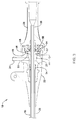
- FIG. 1 is a perspective view of an illustrative vascular access system
- FIG. 2 is a cross-sectional view of the illustrative vascular access system of FIG. 1 , taken at line 2 - 2 ;
- FIG. 3 is an enlarged cross-sectional view of the illustrative hemostasis valve assembly of FIG. 2 ;
- FIG. 4 is a perspective view of an illustrative hemostasis valve
- FIG. 5 is a cross-sectional view of the illustrative hemostasis valve of FIG. 3 , taken at line 5 - 5 in FIG. 4 ;
- FIG. 6A is a proximal end view of the illustrative hemostasis valve of FIG. 3 having a slit configuration
- FIG. 6B is a proximal end view of the illustrative hemostasis valve of FIG. 3 having an alternative slit configuration.
- FIG. 1 is a perspective view of an illustrative vascular access system 10 .
- the vascular access system 10 may be used to gain vessel access during a diagnostic or interventional procedure. While the system 10 is described in terms of vascular access, the system 10 may be used to access other parts of the body.
- the access system 10 may include an introducer sheath 12 and a dilator 14 .
- the introducer sheath 12 includes an elongate shaft 16 and a hemostasis valve assembly 18 .
- the hemostasis valve assembly 18 may include a valve member or gasket which reduces or prevents blood loss when the introducer sheath 12 is inserted into a vessel while allowing for the passage of other devices (e.g., dilators, guide catheters, etc.) through the introducer sheath 12 .
- a valve member or gasket which reduces or prevents blood loss when the introducer sheath 12 is inserted into a vessel while allowing for the passage of other devices (e.g., dilators, guide catheters, etc.) through the introducer sheath 12 .
- the distal tip 30 of the elongate shaft 16 may be tapered to facilitate smooth insertion into the vascular system and/or to provide a smooth transition to the dilator 14 .
- the elongate shaft 16 of the introducer sheath 12 may have a size (outside diameter or profile) ranging from 4 French (F) to 9F, and a length ranging from 10 centimeters (cm) to 25 cm.
- the outer diameter can be smaller than 4F or greater than 9F. It is further contemplated that the length of the shaft 16 may be shorter than 10 cm or longer than 25 cm.
- the hemostasis valve assembly 18 may include a hub body 20 and a strain relief portion 22 coupled to or formed as a unitary structure with the hub body 20 and extending distally therefrom.
- the hub body 20 may include a side port 24 for connection to a flush or injection tube subassembly (not explicitly shown).
- the dilator 14 includes an elongate shaft 26 and a handle 28 . It should be understood that the hemostasis valve assembly 18 , or the components thereof, may be used with other medical devices, such as, but not limited to interventional catheters, diagnostic catheters, guide sheaths, etc.
- FIG. 2 is a cross-sectional view of the illustrative vascular access system 10 of FIG. 1 , taken at line 2 - 2 in FIG. 1 .
- the introducer sheath 12 includes a lumen 32 extending from a proximal end 34 to the distal tip 30 of the elongate shaft 16 .
- the lumen 32 may be sized to receive the dilator 14 , or other device.
- the hemostasis valve assembly 18 is connected to the proximal end 34 of the shaft 16 utilizing conventional techniques.
- the dilator 14 includes a lumen 36 extending from the proximal end 38 to the distal end 40 of the elongate shaft 26 .
- the lumen 36 may be configured to receive a diagnostic or interventional device or therapy.
- the handle 28 may be connected to the proximal end 38 of the elongate shaft 26 of the dilator 14 using conventional techniques.
- a hemostasis valve or gasket 42 is positioned within a cavity 44 of the hub body 20 of the hemostasis valve assembly 18 .
- the hemostasis valve 42 may include one or more interlocking features configured to engage mating features on the hub body 20 to retain the hemostasis valve in a desired position and/or orientation within the hub body 20 (e.g., at a fixed longitudinal and/or axial position within the cavity 44 ).
- the hemostasis valve 42 may include a flanged outer perimeter 46 configured to be received in a mating recess or groove 48 in the hub body 20 .
- the flanged outer perimeter 46 may have an increased thickness (e.g., in the proximal to distal direction, as shown in FIG. 3 ) relative to a pair of annular grooves or recesses 54 , 55 formed in the proximal and distal end surfaces of the hemostasis valve 42 . It is contemplated that the hemostasis valve 42 may be assembled within the cavity 44 of the hub body 20 prior to assembly with an end cap 58 of the hemostasis valve assembly 18 .
- the end cap 58 may include a protrusion 56 configured to engage the annular groove 54 of the hemostasis valve 42 .
- the second annular groove 55 may be configured to engage mating features, such as, but not limited to, a protrusion 57 .
- the end cap 58 may frictionally or interlockingly secure the flanged outer perimeter 46 within the groove 48 and the annular grooves 54 , 55 between the mating protrusions 56 , 57 .
- the distal end 40 of the dilator 14 is advanced distally (e.g., from a proximal side to a distal side of the hemostasis valve 42 ) through one or more slits in the hemostasis valve 42 .
- the slits may be arranged to allow the hemostasis valve 42 to flex in the center, as described in more detail herein.
- FIG. 4 illustrates a perspective view of the illustrative hemostasis valve 42 .
- the hemostasis valve 42 may have a generally cylindrical, puck-like body 41 having a proximal side 50 and a distal side 60 .
- the hemostasis valve 42 may be formed from an elastomeric silicone or other compliant material which allows the hemostasis valve 42 to resume its original shape after temporary deformation (e.g., an applied stress or force less than the yield point or fracture point).
- Some illustrative materials may include, but are not limited to, a liquid silicone rubber (LSR) elastomer or enhanced tear resistant (ETR) silicone elastomers.
- LSR liquid silicone rubber
- EMR enhanced tear resistant
- the proximal side 50 of the hemostasis valve 42 may include a tapered or conical central region 52 with the surface sloped towards the center of the hemostasis valve 42 .
- the tapered central region 52 decreases in diameter from the proximal side 50 towards the distal side 60 of the hemostasis valve 42 .
- the tapered central region 52 may guide the distal end 40 of the dilator 14 towards a diametrical center 53 of the hemostasis valve 42 .
- the tapered central region 52 may act as a self-centering mechanism which automatically guides the distal end 40 of the dilator 14 (or other supplemental medical device) towards the diametrical center 53 of the hemostasis valve 42 as it is assembled with the introducer sheath 12 .
- the self-centering mechanism may facilitate device preparation before a procedure by reducing the force required to push the dilator 14 through the hemostasis valve 42 and/or reduce the number of attempts necessary to pass the dilator through the hemostasis valve
- FIG. 5 illustrates a cross-sectional view of the hemostasis valve 42 , taken at line 5 - 5 in FIG. 4 .
- the distal side 60 of the hemostasis valve 42 may include a distally extending curved or convex central region 62 .
- the curvature of the curved central region 62 may help close the hemostasis valve 42 when blood, or other fluid, pushes against the distal side 60 of the hemostasis valve 42 . It is contemplated that increasing or decreasing the curvature of the curved central region 62 may alter the effectiveness of the closure of the hemostasis valve 42 .
- the flanged outer perimeter 46 may have an increased thickness 51 relative to a pair of annular grooves or recesses 54 , 55 formed in the proximal and distal end surfaces of the hemostasis valve 42 .
- the flanged outer perimeter 46 may be thicker 51 than other portions of the hemostasis valve 42 across the diameter thereof in order provide greater securement within the cavity 44 of the hub body 20 .
- the thickness of the hemostasis valve 42 may vary across the diameter thereof. For example, a thickness 43 adjacent to the annular grooves 54 , 55 may be greater than a thickness 45 adjacent to the diametrical center 53 of the hemostasis valve 42 .
- the thickness of the hemostasis valve 42 adjacent to the center 53 may reduce the force required to advance a device through the hemostasis valve 42 .
- the thickness 51 of the flanged outer perimeter 46 may be the same as, similar to, or different from the other thicknesses 43 , 45 of the hemostasis valve 42 , as desired.
- Other variations in the thickness(es) 43 , 45 , 51 of the hemostasis valve 42 are also contemplated. It is contemplated that changes in thickness may occur in a step-wise, or abrupt, manner or in a gradual, or smooth, manner, as desired. In some cases, the thickness may be uniform across the diameter of the hemostasis valve 42 .
- FIG. 6A illustrates a proximal end view of the hemostasis valve 42 having a slit configuration.
- the tapered central region 52 of the body 41 may include a vertical slit 64 and a horizontal slit 66 extending generally perpendicular to the vertical slit 64 .
- the slits 64 , 66 may both extend entirely through the thickness of the hemostasis valve 42 from the proximal side 50 to the distal side 60 (e.g., in a cross slit thru (CST) configuration).
- the vertical slit 64 may be formed in the proximal side 50 of the hemostasis valve 42 and extend distally partially through the thickness 45 between the tapered central region 52 and the curved central region 62 .
- the horizontal slit 66 may be formed in the distal side 60 of the hemostasis valve 42 and extend proximally partially through the thickness 45 between the tapered central region 52 and the curved central region 62 .
- the slits 64 , 66 may meet between the tapered central region 52 and the curved central region 62 of the hemostasis valve 42 at their intersection point 70 to define an opening extending entirely through the thickness of the hemostasis valve 42 (e.g., in a cross slit partial (CSP) configuration).
- CSP cross slit partial
- the intersection point 70 may be at the diametrical center of the hemostasis valve 42 , although this is not required
- the reverse configuration is also contemplated in which the horizontal slit 66 is formed in the proximal side 50 of the hemostasis valve 42 and extends distally partially through the thickness 45 between the tapered central region 52 and the curved central region 62 and the vertical slit 64 is formed in the distal side 60 of the hemostasis valve 42 and extends proximally partially through the thickness 45 between the tapered central region 52 and the curved central region 62 .
- Other slit variations are also contemplated. For example a first slit may extend through the thickness 45 between the tapered central region 52 and the curved central region 62 while another slit may extend partially through the thickness 45 between the tapered central region 52 and the curved central region 62 .
- the slits 64 , 66 may intersect at the intersection point 70 to define four flaps 68 a , 68 b , 68 c , 68 d (collectively, 68 ).
- the number and orientation of slits 64 , 66 may be varied to vary a number of flaps 68 , as desired. While the slits 64 , 66 are described and shown as extending in a horizontal and vertical orientation, it is contemplated that the slits 64 , 66 may be rotated such that the slits 64 , 66 are offset from the horizontal and vertical axes. It is further contemplated that the slits 64 , 66 may not necessarily intersect at a 90° angle.
- the intersection angle may be varied to create flaps 68 of varying size (e.g., two smaller and two larger).
- the flaps 68 may bend or flex in the distal direction as the dilator 14 is passed through the hemostasis valve 42 .
- the curved central region 62 of the distal side 60 may bias the flaps 68 proximally, causing the flaps 68 to seal around an outer surface of the dilator 14 as well as bringing the flaps 68 into intimate contact adjacent to the slits 64 , 66 .
- FIG. 6B illustrates a proximal end view of the hemostasis valve 42 having an alternative slit configuration.
- the tapered central region 52 of the body 41 may include a plurality of slits 72 a , 72 b , 72 c , 72 d , 72 e (collectively, 72 ).
- the slits 72 may be evenly distributed about the tapered central region 52 .
- the slits 72 may be spaced approximately 72° from one another. It is contemplated that the slits 72 may also be distributed at irregular intervals (e.g., not evenly spaced), as desired.
- the slits 72 may extend entirely through the thickness of the hemostasis valve 42 between the tapered central region 52 and the curved central region 62 from the proximal side 50 to the distal side 60 (e.g., in a star slit thru (SST) configuration). In some embodiments, one or more of the slits 72 may extend partially through the thickness of the hemostasis valve 42 between the tapered central region 52 and the curved central region 62 from either proximal side 50 or the distal side 60 thereof.
- SST star slit thru
- all of the slits 72 may extend entirely through the thickness of the hemostasis valve 42 between the tapered central region 52 and the curved central region 62 , all of the slits 72 may extend partially through the thickness of the hemostasis valve 42 between the tapered central region 52 and the curved central region 62 (from either the proximal side 50 , the distal side 60 , or combinations thereof), or the slits 72 may be a combination of slits that extend entirely or partially through the thickness of the hemostasis valve 42 between the tapered central region 52 and the curved central region 62 .
- the slits 72 may intersect at an intersection point 76 to define five flaps 74 a , 74 b , 74 c , 74 d , 74 e (collectively, 74 ).
- the number and orientation of slits 72 may be varied to vary a number of flaps 74 , as desired. As described herein, the slits 72 may not necessarily intersect at a 72° angle. The intersection angles may be varied to create flaps 74 of varying size.
- the flaps 74 may bend or flex in the distal direction as the dilator 14 is passed through the hemostasis valve 42 .
- the curved central region 62 of the distal side 60 may bias the flaps 74 proximally causing the flaps 74 to seal around an outer surface of the dilator 14 as well as bringing the flaps 74 into intimate contact adjacent to the slits 72 .
- the materials that can be used for the various components of the medical devices and/or systems 10 , 12 , 14 , 18 , 42 (and/or other systems disclosed herein) and the various elements thereof disclosed herein may include those commonly associated with medical devices.
- the following discussion makes reference to the system 10 . However, this is not intended to limit the devices and methods described herein, as the discussion may be applied to other elements, members, components, or devices disclosed herein, such as, but not limited to, the elongate shafts 16 , 26 and the hemostasis valve assembly 18 , and/or elements or components thereof.
- the system 10 may be made from a metal, metal alloy, polymer (some examples of which are disclosed below), a metal-polymer composite, ceramics, combinations thereof, and the like, or other suitable material.
- suitable polymers may include polytetrafluoroethylene (PTFE), ethylene tetrafluoroethylene (ETFE), fluorinated ethylene propylene (FEP), polyoxymethylene (POM, for example, DELRIN® available from DuPont), polyether block ester, polyurethane (for example, Polyurethane 85A), polypropylene (PP), polyvinylchloride (PVC), polyether-ester (for example, ARNITEL® available from DSM Engineering Plastics), ether or ester based copolymers (for example, butylene/poly(alkylene ether) phthalate and/or other polyester elastomers such as HYTREL® available from DuPont), polyamide (for example, DURETHAN® available from Bayer or CRISTAMID® available from Elf Atochem), elastomeric polyamides, block polyamide/ethers, polyether block amide (PEBA, for example available under the trade name PEBAX®), ethylene vinyl acetate
- suitable metals and metal alloys include stainless steel, such as 304V, 304L, and 316LV stainless steel; mild steel; nickel-titanium alloy such as linear-elastic and/or super-elastic nitinol; other nickel alloys such as nickel-chromium-molybdenum alloys (e.g., UNS: N06625 such as INCONEL® 625, UNS: N06022 such as HASTELLOY® C-22®, UNS: N10276 such as HASTELLOY® C276®, other HASTELLOY® alloys, and the like), nickel-copper alloys (e.g., UNS: N04400 such as MONEL® 400, NICKELVAC® 400, NICORROS® 400, and the like), nickel-cobalt-chromium-molybdenum alloys (e.g., UNS: R30035 such as MP35-N® and the like), nickel-molybdenum alloys (e.g.,
- linear elastic and/or non-super-elastic nitinol may be distinguished from super elastic nitinol in that the linear elastic and/or non-super-elastic nitinol does not display a substantial “superelastic plateau” or “flag region” in its stress/strain curve like super elastic nitinol does.
- linear elastic and/or non-super-elastic nitinol as recoverable strain increases, the stress continues to increase in a substantially linear, or a somewhat, but not necessarily entirely linear relationship until plastic deformation begins or at least in a relationship that is more linear than the super elastic plateau and/or flag region that may be seen with super elastic nitinol.
- linear elastic and/or non-super-elastic nitinol may also be termed “substantially” linear elastic and/or non-super-elastic nitinol.
- linear elastic and/or non-super-elastic nitinol may also be distinguishable from super elastic nitinol in that linear elastic and/or non-super-elastic nitinol may accept up to about 2-5% strain while remaining substantially elastic (e.g., before plastically deforming) whereas super elastic nitinol may accept up to about 8% strain before plastically deforming. Both of these materials can be distinguished from other linear elastic materials such as stainless steel (that can also be distinguished based on its composition), which may accept only about 0.2 to 0.44 percent strain before plastically deforming.
- the linear elastic and/or non-super-elastic nickel-titanium alloy is an alloy that does not show any martensite/austenite phase changes that are detectable by differential scanning calorimetry (DSC) and dynamic metal thermal analysis (DMTA) analysis over a large temperature range.
- DSC differential scanning calorimetry
- DMTA dynamic metal thermal analysis
- the mechanical bending properties of such material may therefore be generally inert to the effect of temperature over this very broad range of temperature.
- the mechanical bending properties of the linear elastic and/or non-super-elastic nickel-titanium alloy at ambient or room temperature are substantially the same as the mechanical properties at body temperature, for example, in that they do not display a super-elastic plateau and/or flag region.
- the linear elastic and/or non-super-elastic nickel-titanium alloy maintains its linear elastic and/or non-super-elastic characteristics and/or properties.
- the linear elastic and/or non-super-elastic nickel-titanium alloy may be in the range of about 50 to about 60 weight percent nickel, with the remainder being essentially titanium. In some embodiments, the composition is in the range of about 54 to about 57 weight percent nickel.
- a suitable nickel-titanium alloy is FHP-NT alloy commercially available from Furukawa Techno Material Co. of Kanagawa, Japan. Other suitable materials may include ULTANIUMTM (available from Neo-Metrics) and GUM METALTM (available from Toyota).
- a superelastic alloy for example a superelastic nitinol can be used to achieve desired properties.
- portions or all of system 10 , and/or components thereof, may also be doped with, made of, or otherwise include a radiopaque material.
- Radiopaque materials are understood to be materials capable of producing a relatively bright image on a fluoroscopy screen or another imaging technique during a medical procedure. This relatively bright image aids the user of the medical device system 10 in determining its location.
- Some examples of radiopaque materials can include, but are not limited to, gold, platinum, palladium, tantalum, tungsten alloy, polymer material loaded with a radiopaque filler, and the like. Additionally, other radiopaque marker bands and/or coils may also be incorporated into the design of the medical device system 10 to achieve the same result.
- a degree of Magnetic Resonance Imaging (MRI) compatibility is imparted into the medical device system 10 .
- system 10 and/or components or portions thereof, may be made of a material that does not substantially distort the image and create substantial artifacts (e.g., gaps in the image).
- Certain ferromagnetic materials may not be suitable because they may create artifacts in an MRI image.
- the system 10 or portions thereof, may also be made from a material that the MRI machine can image.
- Some materials that exhibit these characteristics include, for example, tungsten, cobalt-chromium-molybdenum alloys (e.g., UNS: R30003 such as ELGILOY®, PHYNOX®, and the like), nickel-cobalt-chromium-molybdenum alloys (e.g., UNS: R30035 such as MP35-N® and the like), nitinol, and the like, and others.
- cobalt-chromium-molybdenum alloys e.g., UNS: R30003 such as ELGILOY®, PHYNOX®, and the like
- nickel-cobalt-chromium-molybdenum alloys e.g., UNS: R30035 such as MP35-N® and the like
- nitinol and the like, and others.
- an exterior surface of the medical device system 10 may be sandblasted, beadblasted, sodium bicarbonate-blasted, electropolished, etc.
- a coating for example a lubricious, a hydrophilic, a protective, or other type of coating may be applied over portions or all of the outer sheath, or in embodiments without an outer sheath over portions of the delivery system, or other portions of the medical device system 10 .
- Hydrophobic coatings such as fluoropolymers provide a dry lubricity which improves device handling and device exchanges. Lubricious coatings improve steerability and improve lesion crossing capability.
- Suitable lubricious polymers are well known in the art and may include silicone and the like, hydrophilic polymers such as high-density polyethylene (HDPE), polytetrafluoroethylene (PTFE), polyarylene oxides, polyvinylpyrolidones, polyvinylalcohols, hydroxy alkyl cellulosics, algins, saccharides, caprolactones, and the like, and mixtures and combinations thereof. Hydrophilic polymers may be blended among themselves or with formulated amounts of water insoluble compounds (including some polymers) to yield coatings with suitable lubricity, bonding, and solubility.
- hydrophilic polymers such as high-density polyethylene (HDPE), polytetrafluoroethylene (PTFE), polyarylene oxides, polyvinylpyrolidones, polyvinylalcohols, hydroxy alkyl cellulosics, algins, saccharides, caprolactones, and the like, and mixtures and combinations thereof.
- the coating and/or sheath may be formed, for example, by coating, extrusion, co-extrusion, interrupted layer co-extrusion (ILC), or fusing several segments end-to-end.
- the layer may have a uniform stiffness or a gradual reduction in stiffness from the proximal end to the distal end thereof. The gradual reduction in stiffness may be continuous as by ILC or may be stepped as by fusing together separate extruded tubular segments.
- the outer layer may be impregnated with a radiopaque filler material to facilitate radiographic visualization. Those skilled in the art will recognize that these materials can vary widely without deviating from the scope of the present invention.
Landscapes
- Health & Medical Sciences (AREA)
- Heart & Thoracic Surgery (AREA)
- Life Sciences & Earth Sciences (AREA)
- Animal Behavior & Ethology (AREA)
- Public Health (AREA)
- Biomedical Technology (AREA)
- Hematology (AREA)
- Engineering & Computer Science (AREA)
- Pulmonology (AREA)
- General Health & Medical Sciences (AREA)
- Anesthesiology (AREA)
- Veterinary Medicine (AREA)
- Biophysics (AREA)
- Infusion, Injection, And Reservoir Apparatuses (AREA)
- Media Introduction/Drainage Providing Device (AREA)
- Prostheses (AREA)
- Materials For Medical Uses (AREA)
Priority Applications (2)
| Application Number | Priority Date | Filing Date | Title |
|---|---|---|---|
| US15/806,315 US10835729B2 (en) | 2016-11-09 | 2017-11-07 | Hemostasis valve design for introducer sheath |
| US17/063,807 US11779743B2 (en) | 2016-11-09 | 2020-10-06 | Hemostasis valve design for introducer sheath |
Applications Claiming Priority (2)
| Application Number | Priority Date | Filing Date | Title |
|---|---|---|---|
| US201662419670P | 2016-11-09 | 2016-11-09 | |
| US15/806,315 US10835729B2 (en) | 2016-11-09 | 2017-11-07 | Hemostasis valve design for introducer sheath |
Related Child Applications (1)
| Application Number | Title | Priority Date | Filing Date |
|---|---|---|---|
| US17/063,807 Continuation US11779743B2 (en) | 2016-11-09 | 2020-10-06 | Hemostasis valve design for introducer sheath |
Publications (2)
| Publication Number | Publication Date |
|---|---|
| US20180126142A1 US20180126142A1 (en) | 2018-05-10 |
| US10835729B2 true US10835729B2 (en) | 2020-11-17 |
Family
ID=60409446
Family Applications (2)
| Application Number | Title | Priority Date | Filing Date |
|---|---|---|---|
| US15/806,315 Active 2038-08-28 US10835729B2 (en) | 2016-11-09 | 2017-11-07 | Hemostasis valve design for introducer sheath |
| US17/063,807 Active 2038-12-25 US11779743B2 (en) | 2016-11-09 | 2020-10-06 | Hemostasis valve design for introducer sheath |
Family Applications After (1)
| Application Number | Title | Priority Date | Filing Date |
|---|---|---|---|
| US17/063,807 Active 2038-12-25 US11779743B2 (en) | 2016-11-09 | 2020-10-06 | Hemostasis valve design for introducer sheath |
Country Status (5)
| Country | Link |
|---|---|
| US (2) | US10835729B2 (fr) |
| EP (1) | EP3538191A1 (fr) |
| JP (1) | JP6861290B2 (fr) |
| CN (1) | CN110430912B (fr) |
| WO (1) | WO2018089390A1 (fr) |
Families Citing this family (4)
| Publication number | Priority date | Publication date | Assignee | Title |
|---|---|---|---|---|
| US10556091B2 (en) * | 2014-05-07 | 2020-02-11 | St. Jude Medical, Cardiology Division, Inc. | Threaded, locking handle mechanism for attaching to shaft |
| US10835729B2 (en) | 2016-11-09 | 2020-11-17 | Boston Scientific Limited | Hemostasis valve design for introducer sheath |
| CN111375118A (zh) * | 2018-12-29 | 2020-07-07 | 微创神通医疗科技(上海)有限公司 | 导引装置及导引系统 |
| CN115337521A (zh) * | 2022-10-19 | 2022-11-15 | 上海汇禾医疗器械有限公司 | 一种具有止血阀的导管鞘装置 |
Citations (20)
| Publication number | Priority date | Publication date | Assignee | Title |
|---|---|---|---|---|
| US5092857A (en) | 1991-05-17 | 1992-03-03 | Fleischhacker John J | Hemostasis valve having support shoulders |
| WO1995034341A1 (fr) | 1994-05-12 | 1995-12-21 | C.R. Bard, Inc. | Embout d'introduction de catheter |
| JPH0947512A (ja) | 1995-08-10 | 1997-02-18 | Nippon Zeon Co Ltd | 医用弁体及び医用挿入補助具 |
| JPH10127775A (ja) | 1996-10-25 | 1998-05-19 | Nippon Zeon Co Ltd | 医用弁体および医用挿入補助具 |
| US5935112A (en) | 1997-10-15 | 1999-08-10 | Stevens; Brian W. | Hemostasis valve with catheter/guidewire seals |
| US6086570A (en) | 1998-09-29 | 2000-07-11 | A-Med Systems, Inc. | Hemostasis valve with membranes having offset apertures |
| US6702255B2 (en) | 2001-11-08 | 2004-03-09 | Edwards Lifesciences Corporation | H-shape duckbill hemostasis valve assembly including guide wire seal |
| US20050010238A1 (en) | 2003-07-08 | 2005-01-13 | Potter Daniel J. | Detachable hemostasis valve and splittable sheath assembly |
| US20060145116A1 (en) | 2005-01-04 | 2006-07-06 | Claude Rickerd | Splittable hemostasis valve |
| US20090012476A1 (en) | 2007-07-05 | 2009-01-08 | Galt Medical Corporation | Hemostasis valve for a catheter introducer |
| US20100312190A1 (en) | 2009-06-09 | 2010-12-09 | Oscor Inc. | Low insertion force hemostasis valve for vascular introducer |
| EP2404638A1 (fr) | 2010-07-05 | 2012-01-11 | Aust Development, LLC | Vannes et moyeux en série pour dispositifs tubulaires et procédés de fabrication et d'utilisation associés |
| US20120065676A1 (en) | 2004-08-19 | 2012-03-15 | Tyco Healthcare Group Lp | Water-Swellable Copolymers and Articles and Coatings Made Therefrom |
| US20130310765A1 (en) * | 2012-05-17 | 2013-11-21 | Medical Components, Inc. | Valve for dilator and sheath assembly |
| US20140039263A1 (en) | 2012-08-03 | 2014-02-06 | St. Jude Medical Puerto Rico Llc | Large bore introducer with improved seal |
| US20140277340A1 (en) | 2013-03-15 | 2014-09-18 | Bolton Medical, Inc. | Hemostasis Valve and Delivery Systems |
| US9108032B2 (en) | 2009-03-12 | 2015-08-18 | Cook Medical Technologies Llc | Hemostasis valve assembly |
| JP2015205219A (ja) | 2008-05-05 | 2015-11-19 | ベクトン・ディキンソン・アンド・カンパニーBecton, Dickinson And Company | 回転作動血液制御弁 |
| US20160175576A1 (en) * | 2014-12-22 | 2016-06-23 | Cook Medical Technologies Llc | Hemostatic valve system |
| US20180126142A1 (en) | 2016-11-09 | 2018-05-10 | Boston Scientific Limited | Hemostasis valve design for introducer sheath |
Family Cites Families (9)
| Publication number | Priority date | Publication date | Assignee | Title |
|---|---|---|---|---|
| US7637893B2 (en) * | 2004-04-30 | 2009-12-29 | C. R. Bard, Inc. | Valved sheath introducer for venous cannulation |
| WO2009041522A1 (fr) | 2007-09-27 | 2009-04-02 | Terumo Kabushiki Kaisha | Élément de soupape et instrument médical |
| US8366684B2 (en) * | 2008-05-12 | 2013-02-05 | Becton, Dickinson And Company | Intravenous catheter blood control device |
| US8454579B2 (en) * | 2009-03-25 | 2013-06-04 | Icu Medical, Inc. | Medical connector with automatic valves and volume regulator |
| US9155864B2 (en) * | 2011-10-06 | 2015-10-13 | Becton, Dickinson And Company | Multiple use blood control valve with center and circumferential slits |
| US8911397B2 (en) * | 2011-12-22 | 2014-12-16 | Boston Scientific Scimed Inc. | Steerable sheath handle pulley mechanism |
| JP5928064B2 (ja) * | 2012-03-27 | 2016-06-01 | 株式会社カネカ | 医療機器用弁体、医療機器、および医療機器用弁体の製造方法 |
| US10105085B2 (en) * | 2012-11-03 | 2018-10-23 | ProVazo LLC | Directing hub used with vascular blood sampling catheter |
| KR102465136B1 (ko) * | 2013-03-15 | 2022-11-10 | 인튜어티브 서지컬 오퍼레이션즈 인코포레이티드 | 다수의 수술 도구 밀봉 |
-
2017
- 2017-11-07 US US15/806,315 patent/US10835729B2/en active Active
- 2017-11-07 EP EP17801244.9A patent/EP3538191A1/fr active Pending
- 2017-11-07 WO PCT/US2017/060479 patent/WO2018089390A1/fr unknown
- 2017-11-07 CN CN201780081515.0A patent/CN110430912B/zh active Active
- 2017-11-07 JP JP2019545890A patent/JP6861290B2/ja active Active
-
2020
- 2020-10-06 US US17/063,807 patent/US11779743B2/en active Active
Patent Citations (25)
| Publication number | Priority date | Publication date | Assignee | Title |
|---|---|---|---|---|
| US5092857A (en) | 1991-05-17 | 1992-03-03 | Fleischhacker John J | Hemostasis valve having support shoulders |
| WO1995034341A1 (fr) | 1994-05-12 | 1995-12-21 | C.R. Bard, Inc. | Embout d'introduction de catheter |
| JPH10500345A (ja) | 1994-05-12 | 1998-01-13 | シー・アール・バード・インク | カテーテル導入器 |
| JPH0947512A (ja) | 1995-08-10 | 1997-02-18 | Nippon Zeon Co Ltd | 医用弁体及び医用挿入補助具 |
| JPH10127775A (ja) | 1996-10-25 | 1998-05-19 | Nippon Zeon Co Ltd | 医用弁体および医用挿入補助具 |
| US5935112A (en) | 1997-10-15 | 1999-08-10 | Stevens; Brian W. | Hemostasis valve with catheter/guidewire seals |
| US6086570A (en) | 1998-09-29 | 2000-07-11 | A-Med Systems, Inc. | Hemostasis valve with membranes having offset apertures |
| US6702255B2 (en) | 2001-11-08 | 2004-03-09 | Edwards Lifesciences Corporation | H-shape duckbill hemostasis valve assembly including guide wire seal |
| US20050010238A1 (en) | 2003-07-08 | 2005-01-13 | Potter Daniel J. | Detachable hemostasis valve and splittable sheath assembly |
| US20120065676A1 (en) | 2004-08-19 | 2012-03-15 | Tyco Healthcare Group Lp | Water-Swellable Copolymers and Articles and Coatings Made Therefrom |
| US20060145116A1 (en) | 2005-01-04 | 2006-07-06 | Claude Rickerd | Splittable hemostasis valve |
| US8371555B2 (en) | 2005-01-04 | 2013-02-12 | Pacesetter, Inc. | Splittable hemostasis valve |
| US20090012476A1 (en) | 2007-07-05 | 2009-01-08 | Galt Medical Corporation | Hemostasis valve for a catheter introducer |
| JP2015205219A (ja) | 2008-05-05 | 2015-11-19 | ベクトン・ディキンソン・アンド・カンパニーBecton, Dickinson And Company | 回転作動血液制御弁 |
| US9108032B2 (en) | 2009-03-12 | 2015-08-18 | Cook Medical Technologies Llc | Hemostasis valve assembly |
| US20100312190A1 (en) | 2009-06-09 | 2010-12-09 | Oscor Inc. | Low insertion force hemostasis valve for vascular introducer |
| EP2404638A1 (fr) | 2010-07-05 | 2012-01-11 | Aust Development, LLC | Vannes et moyeux en série pour dispositifs tubulaires et procédés de fabrication et d'utilisation associés |
| US20130310765A1 (en) * | 2012-05-17 | 2013-11-21 | Medical Components, Inc. | Valve for dilator and sheath assembly |
| US20140039263A1 (en) | 2012-08-03 | 2014-02-06 | St. Jude Medical Puerto Rico Llc | Large bore introducer with improved seal |
| US20140277340A1 (en) | 2013-03-15 | 2014-09-18 | Bolton Medical, Inc. | Hemostasis Valve and Delivery Systems |
| US9439751B2 (en) | 2013-03-15 | 2016-09-13 | Bolton Medical, Inc. | Hemostasis valve and delivery systems |
| US20160338867A1 (en) | 2013-03-15 | 2016-11-24 | Bolton Medical, Inc. | Hemostasis valve and delivery systems |
| US20160175576A1 (en) * | 2014-12-22 | 2016-06-23 | Cook Medical Technologies Llc | Hemostatic valve system |
| EP3037126A1 (fr) | 2014-12-22 | 2016-06-29 | Cook Medical Technologies LLC | Système avec valve hémostatique |
| US20180126142A1 (en) | 2016-11-09 | 2018-05-10 | Boston Scientific Limited | Hemostasis valve design for introducer sheath |
Non-Patent Citations (1)
| Title |
|---|
| International Search Report and Written Opinion for Application No. PCT/US2017/060479, 14 pages, dated Jan. 30, 2018. |
Also Published As
| Publication number | Publication date |
|---|---|
| US20180126142A1 (en) | 2018-05-10 |
| JP2019534133A (ja) | 2019-11-28 |
| CN110430912B (zh) | 2021-11-02 |
| US11779743B2 (en) | 2023-10-10 |
| WO2018089390A1 (fr) | 2018-05-17 |
| EP3538191A1 (fr) | 2019-09-18 |
| JP6861290B2 (ja) | 2021-04-21 |
| US20210023358A1 (en) | 2021-01-28 |
| CN110430912A (zh) | 2019-11-08 |
Similar Documents
| Publication | Publication Date | Title |
|---|---|---|
| US11571545B2 (en) | Guide extension catheter | |
| US20230093564A1 (en) | Low pressure seal design for a hemostasis valve | |
| US11779743B2 (en) | Hemostasis valve design for introducer sheath | |
| US9486611B2 (en) | Guide extension catheter | |
| US20140018773A1 (en) | Guide extension catheter | |
| US20140025043A1 (en) | Guide extension catheter | |
| US10953196B2 (en) | Catheter hubs | |
| US20150352330A1 (en) | Deliver assist device for guide catheter | |
| US10737060B2 (en) | Catheter hubs | |
| US20150148706A1 (en) | Medical devices for accessing body lumens | |
| US10195392B2 (en) | Clip-on catheter | |
| US20230011214A1 (en) | Radially clocked steerable catheter | |
| US20240065717A1 (en) | Cannulation Devices For Endoscopic Retrograde Cholangiopancreatography (ERCP) | |
| US20240100303A1 (en) | Flexible lockable microcatheter and guidewire co-axial system |
Legal Events
| Date | Code | Title | Description |
|---|---|---|---|
| FEPP | Fee payment procedure |
Free format text: ENTITY STATUS SET TO UNDISCOUNTED (ORIGINAL EVENT CODE: BIG.); ENTITY STATUS OF PATENT OWNER: LARGE ENTITY |
|
| AS | Assignment |
Owner name: BOSTON SCIENTIFIC LIMITED, BERMUDA Free format text: ASSIGNMENT OF ASSIGNORS INTEREST;ASSIGNORS:AGRAWAL, SUMIT;PEPIN, HENRY J.;REDDY, SOMASHEKAR;SIGNING DATES FROM 20171002 TO 20171003;REEL/FRAME:045109/0753 |
|
| STPP | Information on status: patent application and granting procedure in general |
Free format text: DOCKETED NEW CASE - READY FOR EXAMINATION |
|
| STPP | Information on status: patent application and granting procedure in general |
Free format text: NON FINAL ACTION MAILED |
|
| STPP | Information on status: patent application and granting procedure in general |
Free format text: RESPONSE TO NON-FINAL OFFICE ACTION ENTERED AND FORWARDED TO EXAMINER |
|
| STPP | Information on status: patent application and granting procedure in general |
Free format text: FINAL REJECTION MAILED |
|
| STPP | Information on status: patent application and granting procedure in general |
Free format text: RESPONSE AFTER FINAL ACTION FORWARDED TO EXAMINER |
|
| STPP | Information on status: patent application and granting procedure in general |
Free format text: NOTICE OF ALLOWANCE MAILED -- APPLICATION RECEIVED IN OFFICE OF PUBLICATIONS |
|
| STPP | Information on status: patent application and granting procedure in general |
Free format text: NOTICE OF ALLOWANCE MAILED -- APPLICATION RECEIVED IN OFFICE OF PUBLICATIONS |
|
| STPP | Information on status: patent application and granting procedure in general |
Free format text: PUBLICATIONS -- ISSUE FEE PAYMENT RECEIVED |
|
| STCF | Information on status: patent grant |
Free format text: PATENTED CASE |
|
| AS | Assignment |
Owner name: BOSTON SCIENTIFIC MEDICAL DEVICE LIMITED, IRELAND Free format text: ASSIGNMENT OF ASSIGNORS INTEREST;ASSIGNOR:BOSTON SCIENTIFIC LIMITED;REEL/FRAME:065580/0083 Effective date: 20191231 |
|
| MAFP | Maintenance fee payment |
Free format text: PAYMENT OF MAINTENANCE FEE, 4TH YEAR, LARGE ENTITY (ORIGINAL EVENT CODE: M1551); ENTITY STATUS OF PATENT OWNER: LARGE ENTITY Year of fee payment: 4 |