US10835014B2 - Liquid dispenser - Google Patents
Liquid dispenser Download PDFInfo
- Publication number
- US10835014B2 US10835014B2 US16/315,489 US201716315489A US10835014B2 US 10835014 B2 US10835014 B2 US 10835014B2 US 201716315489 A US201716315489 A US 201716315489A US 10835014 B2 US10835014 B2 US 10835014B2
- Authority
- US
- United States
- Prior art keywords
- liquid dispenser
- liquid
- coupling
- container unit
- main unit
- Prior art date
- Legal status (The legal status is an assumption and is not a legal conclusion. Google has not performed a legal analysis and makes no representation as to the accuracy of the status listed.)
- Active, expires
Links
Images


Classifications
-
- B—PERFORMING OPERATIONS; TRANSPORTING
- B05—SPRAYING OR ATOMISING IN GENERAL; APPLYING FLUENT MATERIALS TO SURFACES, IN GENERAL
- B05B—SPRAYING APPARATUS; ATOMISING APPARATUS; NOZZLES
- B05B11/00—Single-unit hand-held apparatus in which flow of contents is produced by the muscular force of the operator at the moment of use
- B05B11/0005—Components or details
- B05B11/0037—Containers
- B05B11/0054—Cartridges, i.e. containers specially designed for easy attachment to or easy removal from the rest of the sprayer
-
- A—HUMAN NECESSITIES
- A45—HAND OR TRAVELLING ARTICLES
- A45D—HAIRDRESSING OR SHAVING EQUIPMENT; EQUIPMENT FOR COSMETICS OR COSMETIC TREATMENTS, e.g. FOR MANICURING OR PEDICURING
- A45D34/00—Containers or accessories specially adapted for handling liquid toiletry or cosmetic substances, e.g. perfumes
- A45D34/04—Appliances specially adapted for applying liquid, e.g. using roller or ball
- A45D34/041—Appliances specially adapted for applying liquid, e.g. using roller or ball using a roller, a disc or a ball
-
- A—HUMAN NECESSITIES
- A45—HAND OR TRAVELLING ARTICLES
- A45D—HAIRDRESSING OR SHAVING EQUIPMENT; EQUIPMENT FOR COSMETICS OR COSMETIC TREATMENTS, e.g. FOR MANICURING OR PEDICURING
- A45D34/00—Containers or accessories specially adapted for handling liquid toiletry or cosmetic substances, e.g. perfumes
- A45D34/04—Appliances specially adapted for applying liquid, e.g. using roller or ball
- A45D34/042—Appliances specially adapted for applying liquid, e.g. using roller or ball using a brush or the like
-
- B—PERFORMING OPERATIONS; TRANSPORTING
- B05—SPRAYING OR ATOMISING IN GENERAL; APPLYING FLUENT MATERIALS TO SURFACES, IN GENERAL
- B05B—SPRAYING APPARATUS; ATOMISING APPARATUS; NOZZLES
- B05B11/00—Single-unit hand-held apparatus in which flow of contents is produced by the muscular force of the operator at the moment of use
- B05B11/0005—Components or details
- B05B11/0035—Pen-like sprayers
-
- B—PERFORMING OPERATIONS; TRANSPORTING
- B05—SPRAYING OR ATOMISING IN GENERAL; APPLYING FLUENT MATERIALS TO SURFACES, IN GENERAL
- B05B—SPRAYING APPARATUS; ATOMISING APPARATUS; NOZZLES
- B05B11/00—Single-unit hand-held apparatus in which flow of contents is produced by the muscular force of the operator at the moment of use
- B05B11/0005—Components or details
- B05B11/0037—Containers
- B05B11/0038—Inner container disposed in an outer shell or outer casing
-
- B—PERFORMING OPERATIONS; TRANSPORTING
- B05—SPRAYING OR ATOMISING IN GENERAL; APPLYING FLUENT MATERIALS TO SURFACES, IN GENERAL
- B05B—SPRAYING APPARATUS; ATOMISING APPARATUS; NOZZLES
- B05B11/00—Single-unit hand-held apparatus in which flow of contents is produced by the muscular force of the operator at the moment of use
- B05B11/01—Single-unit hand-held apparatus in which flow of contents is produced by the muscular force of the operator at the moment of use characterised by the means producing the flow
- B05B11/10—Pump arrangements for transferring the contents from the container to a pump chamber by a sucking effect and forcing the contents out through the dispensing nozzle
- B05B11/1042—Components or details
- B05B11/1043—Sealing or attachment arrangements between pump and container
- B05B11/1046—Sealing or attachment arrangements between pump and container the pump chamber being arranged substantially coaxially to the neck of the container
- B05B11/1047—Sealing or attachment arrangements between pump and container the pump chamber being arranged substantially coaxially to the neck of the container the pump being preassembled as an independent unit before being mounted on the container
-
- B05B11/3047—
-
- B—PERFORMING OPERATIONS; TRANSPORTING
- B05—SPRAYING OR ATOMISING IN GENERAL; APPLYING FLUENT MATERIALS TO SURFACES, IN GENERAL
- B05C—APPARATUS FOR APPLYING FLUENT MATERIALS TO SURFACES, IN GENERAL
- B05C1/00—Apparatus in which liquid or other fluent material is applied to the surface of the work by contact with a member carrying the liquid or other fluent material, e.g. a porous member loaded with a liquid to be applied as a coating
- B05C1/04—Apparatus in which liquid or other fluent material is applied to the surface of the work by contact with a member carrying the liquid or other fluent material, e.g. a porous member loaded with a liquid to be applied as a coating for applying liquid or other fluent material to work of indefinite length
- B05C1/06—Apparatus in which liquid or other fluent material is applied to the surface of the work by contact with a member carrying the liquid or other fluent material, e.g. a porous member loaded with a liquid to be applied as a coating for applying liquid or other fluent material to work of indefinite length by rubbing contact, e.g. by brushes, by pads
-
- A—HUMAN NECESSITIES
- A45—HAND OR TRAVELLING ARTICLES
- A45D—HAIRDRESSING OR SHAVING EQUIPMENT; EQUIPMENT FOR COSMETICS OR COSMETIC TREATMENTS, e.g. FOR MANICURING OR PEDICURING
- A45D2200/00—Details not otherwise provided for in A45D
- A45D2200/05—Details of containers
- A45D2200/054—Means for supplying liquid to the outlet of the container
- A45D2200/055—Piston or plunger for supplying the liquid to the applicator
-
- A—HUMAN NECESSITIES
- A45—HAND OR TRAVELLING ARTICLES
- A45D—HAIRDRESSING OR SHAVING EQUIPMENT; EQUIPMENT FOR COSMETICS OR COSMETIC TREATMENTS, e.g. FOR MANICURING OR PEDICURING
- A45D2200/00—Details not otherwise provided for in A45D
- A45D2200/05—Details of containers
- A45D2200/054—Means for supplying liquid to the outlet of the container
- A45D2200/057—Spray nozzles; Generating atomised liquid
-
- A—HUMAN NECESSITIES
- A46—BRUSHWARE
- A46B—BRUSHES
- A46B11/00—Brushes with reservoir or other means for applying substances, e.g. paints, pastes, water
- A46B11/001—Brushes with reservoir or other means for applying substances, e.g. paints, pastes, water with integral reservoirs
- A46B11/0065—Brushes where the reservoir is specifically intended for being replaced when empty
-
- A—HUMAN NECESSITIES
- A46—BRUSHWARE
- A46B—BRUSHES
- A46B11/00—Brushes with reservoir or other means for applying substances, e.g. paints, pastes, water
- A46B11/0072—Details
- A46B11/0075—Means integral with the brush for opening, puncturing or piercing sealed reservoirs, e.g. on insertion
-
- B—PERFORMING OPERATIONS; TRANSPORTING
- B05—SPRAYING OR ATOMISING IN GENERAL; APPLYING FLUENT MATERIALS TO SURFACES, IN GENERAL
- B05C—APPARATUS FOR APPLYING FLUENT MATERIALS TO SURFACES, IN GENERAL
- B05C17/00—Hand tools or apparatus using hand held tools, for applying liquids or other fluent materials to, for spreading applied liquids or other fluent materials on, or for partially removing applied liquids or other fluent materials from, surfaces
- B05C17/005—Hand tools or apparatus using hand held tools, for applying liquids or other fluent materials to, for spreading applied liquids or other fluent materials on, or for partially removing applied liquids or other fluent materials from, surfaces for discharging material from a reservoir or container located in or on the hand tool through an outlet orifice by pressure without using surface contacting members like pads or brushes
- B05C17/00569—Hand tools or apparatus using hand held tools, for applying liquids or other fluent materials to, for spreading applied liquids or other fluent materials on, or for partially removing applied liquids or other fluent materials from, surfaces for discharging material from a reservoir or container located in or on the hand tool through an outlet orifice by pressure without using surface contacting members like pads or brushes with a pump in the hand tool
-
- B—PERFORMING OPERATIONS; TRANSPORTING
- B05—SPRAYING OR ATOMISING IN GENERAL; APPLYING FLUENT MATERIALS TO SURFACES, IN GENERAL
- B05C—APPARATUS FOR APPLYING FLUENT MATERIALS TO SURFACES, IN GENERAL
- B05C17/00—Hand tools or apparatus using hand held tools, for applying liquids or other fluent materials to, for spreading applied liquids or other fluent materials on, or for partially removing applied liquids or other fluent materials from, surfaces
- B05C17/005—Hand tools or apparatus using hand held tools, for applying liquids or other fluent materials to, for spreading applied liquids or other fluent materials on, or for partially removing applied liquids or other fluent materials from, surfaces for discharging material from a reservoir or container located in or on the hand tool through an outlet orifice by pressure without using surface contacting members like pads or brushes
- B05C17/00586—Means, generally located near the nozzle, for piercing or perforating the front part of a cartridge
Definitions
- the invention relates to a liquid dispenser for discharging pharmaceutical or cosmetic liquids and to a set comprising such a liquid dispenser.
- the invention here relates in particular to liquid dispensers which have a rod shape, comprising a housing which is elongated in the direction of a direction of principal extent and at the end of which is provided the discharge opening, wherein this liquid dispenser can be guided similarly to a pen, between thumb, index finger and middle finger, in order to discharge liquid.
- Dispensers of the generic type possess a liquid store and a pumping device in order to convey liquid from the liquid store to the discharge opening.
- Dispensers of the generic type and more particularly those in a rod shape, are well suited, in particular, to the discharge of cosmetic liquids, since, by virtue of the pen-like handling, they enable a particularly precise discharge as regards discharge quantity and discharge location.
- a typical liquid dispenser in rod shape is known, for instance, from DE 102011007405 A1.
- the liquid dispenser which is disclosed therein possesses a liquid store, which is an integral component part of the dispenser and, together with this, constitutes a disposable article.
- the object of the invention is to provide a liquid dispenser which allows parts of the dispenser to be reused following emptying of the liquid store.
- the liquid dispenser for discharging pharmaceutical or cosmetic liquids, which is designed as follows:
- the liquid dispenser has a liquid store for receiving the liquid prior to discharge. It further has a discharge opening for discharging the liquid, and a pumping device having an actuating surface for the manual actuation of the pumping device, by means of which liquid is conveyed from the liquid store to the discharge opening.
- the liquid store is provided within an exchangeable container unit, which is couplable to a main unit comprising the pumping device and preferably also the discharge opening, and is uncouplable therefrom.
- the container unit and the main unit are couplable via a coupling device, by means of which the container unit, by pressing against the main unit, is alternately couplable thereto and releasable therefrom.
- This coupling device possesses two coupling members, wherein one coupling member is provided on the container unit and one coupling member on the main unit.
- said container unit is thus provided as an exchangeable unit. While the main unit, comprising the pumping device and preferably also the discharge opening, is provided, as designated, for a lengthy use, the container unit which comprises the liquid dispenser is intended to be exchanged. This allows, on the one hand, an already completely emptied container unit to be exchanged for a new, full container unit. Furthermore, it is also here possible for the user to use various containers whose content is of the same generic type yet different, for instance various sorts of make-up, on an ad hoc basis in turns.
- the subject of the invention is, in particular, how the coupling device for connecting the container unit functions.
- This coupling device is configured to allow both the coupling and the uncoupling of the container unit, by applying a force to the container unit in the direction of the main unit.
- a consistent application of force to the container unit is provided both for the coupling and for the uncoupling.
- the liquid dispenser preferably has a rod shape, the process for the coupling and uncoupling accordingly virtually corresponds to the process with which, in retractable ballpoint pens, the pen tip can be extended and retracted again in turns.
- the main unit possesses a receiving shaft into which the container unit is inserted.
- a receiving shaft stabilizes the connected container unit and, by virtue of its design as part of the main unit, can be designed in higher quality than external walls of the container unit which is exchangeable in the designated manner.
- a coupling device which, for the uncoupling of the container unit, provides an application of force in a separation direction opposite to the slide-in direction, would make it necessary for the container unit to project in relevant measure from the receiving shaft in order to be able to be gripped for the purpose of the exchange.
- the container unit in the connected state, can by contrast be found in a position set back from the rim of the receiving shaft, and yet can be uncouplable through the opening in the receiving shaft.
- the extent by which the end of the container unit is set back amounts to a few millimeters.
- the container unit can, however, also protrude slightly. This can in particular be expedient in order to be able to detect from outside what type of a container unit is used.
- various container units have on their segment protruding from the receiving shaft a color coding.
- an end-side labeling of the container is also conceivable, so that it is possible to detect the type of container unit used, where appropriate situated in a set-back position, from this end face, which is still visible in the receiving shaft.
- the two coupling members are matched to one another in such a way that, in a state inserted one into the other, they are rotatable relative to one another about a rotational axis.
- the corresponding rotational axis is preferably defined by the geometry of the coupling members.
- an internal wall of the receiving shaft and an external wall of the container unit can be of circular design and provided with virtually identical diameter, so that these walls define the rotational axis.
- the coupling members on one of the coupling members is provided at least one retaining cam, and on the other coupling member is provided a corresponding retaining structure having stop faces interrupted in the peripheral direction by gaps, so that the coupling members, in one relative rotation setting, can be released from one another in the direction of the rotational axis when the retaining cam is aligned with a gap.
- the coupling members in another relative rotation setting, in which the retaining cam is aligned with a stop face, the coupling members, by contrast, are secured against axial pulling apart.
- stop faces which are separated from one another by gaps.
- the retaining cam provided on sides of the other coupling member is arranged in a rotation setting in alignment with the gaps, so that they can intrude behind those gaps. In another rotation setting, it is in this case aligned with the stop faces, so that it is thus positively secured against direct withdrawal.
- one retaining cam is sufficient.
- more retaining cams which are mutually offset in the peripheral direction, in particular two retaining cams on mutually opposite sides, or for each stop face, respectively an assigned retaining cam, can also be provided.
- On at least one of the coupling members is preferably provided a gearing-like ramp structure, and on the other coupling device a hereto corresponding mating surface, by which the two coupling devices are rotated relative to one another about the rotational axis into a defined desired relative rotation setting when they are pushed axially toward one another.
- the number of single ramps of the ramp structure which act in one of the rotational directions here preferably tallies with the sum of the gaps and the gaps provided between them. In particular, it is preferably a case of four or more ramps arranged in the same rotational direction on the gearing-like ramp structure.
- a ramp structure provided on a coupling member, but also the corresponding mating surface is provided in the form of a ramp structure.
- These mutually facing structures which are preferably configured in the manner of a spur gearing, enter into engagement with one another when the container unit, starting from the connected or disconnected state, is pressed as far as possible onto the coupling member of the main unit.
- inclined sliding surfaces extended in the peripheral direction are preferably respectively provided between the gaps and the stop faces, wherein, in said desired relative rotation settings, the retaining cam is oriented in such a way relative to the retaining structure that it is aligned with one of the sliding surfaces.
- the sliding surfaces ensure that the retaining cam or retaining cams, when moved toward the retaining structure, are shifted out of the transition regions between stop faces and gaps slightly in the peripheral direction, so as either to land on a stop face or be inserted into a gap, so that the main unit and the container unit can be separated from one another.
- the designated process in a design comprising one of the aforementioned ramp structures, which generates the desired relative rotation settings, and the described sliding surfaces, is as follows: when the container unit, for coupling purposes, is pressed for the first time onto the main unit, then the retaining cam at the same time crosses one of the gaps provided between the stop faces.
- the rotation setting in which the retaining cam can be guided through the gap is therefore one which subsequently, due to the ramp structure and the mating surfaces, causes a slight rotation of the container unit and the main unit relative to one another.
- This rotation is sufficient to, upon a subsequently occurring opposite relative movement in the axial direction of the container unit relative to the main unit, cause the retaining cam to land on one of the sliding surfaces, wherein this sliding surface is angled such that the retaining cam, after the slight relative rotation movement, lands on a stop face.
- the connected state is thereby established.
- a spring device in particular in the form of a helical spring, can preferably be provided, which spring device, in the coupled state of the coupling device between the coupling members, applies to these a mutually opposing force in a separation direction.
- the spring device ensures that a pressing together of the coupling members can only take place upon simultaneous deformation of the spring device, and thus against the force thereof. The result is that, after force has been applied to the coupling members to bring them closer together, the coupling members spontaneously easily separate from one another again in order that, in the course of this movement, the retaining cam can land on the sliding surface.
- the spring device can in particular be fixed to one of the coupling members and extend in the direction of the other coupling member.
- On the other coupling member is preferably provided a guide structure for the spring, which guides the spring during the convergence of the coupling members.
- the spring device is configured in one piece with one of the coupling devices.
- the use of a part of the coupling device which is configured in one piece preferably as a plastics part is advantageous from a production engineering aspect.
- the spring device is provided on the coupling member assigned to the main unit, in such an integrally provided plastics spring it can be advantageous if this is provided on the coupling member of the container unit, since its necessary life is hereby limited, and thus relaxation phenomena in the plastics spring have less relevance. If a metallic spring is used, then this is preferably fixed on sides of the main unit.
- the container unit possesses an outlet opening, through which the liquid can flow in the direction of the pumping device.
- this outlet opening is preferably closed off by a membrane.
- an opening sleeve for the opening of this closure, on one of the coupling members of the main unit can be provided an opening sleeve, which, upon the coupling of the container unit, punctures the membrane and thereby opens the container unit.
- the closure of the container unit with a membrane in the delivery state enables the opening action to be realized solely through the insertion of the container unit, in that the membrane is pressed against the opening sleeve, which latter is preferably provided with a cutting tip.
- a membrane can be an integral part of the container-side coupling member or be welded or adhered to the latter.
- An alternative design to a membrane provides that a closing ball bears against the opening of the container unit, which closing ball is held in position by slight overpressure in the container unit.
- the opening sleeve can also be used to arrange on its outer side the retaining cam or a plurality of retaining cams.
- the coupling members preferably also possess a common clamping device, by which the coupling devices, in a relative setting in which they are spaced further apart compared to the positively secured relative setting, are fixable relative to one another.
- the clamping device is a non-positively or positively acting clamping device, which, in the designated manner, upon the insertion and/or upon the withdrawal of the container unit from the main unit, in an intermediate setting positionally fix the main unit and the container unit relative to one another, said fixing being easily surmountable.
- the punctured membrane in interaction with the opening sleeve, can form this clamping device.
- the container unit can be withdrawn in a non-destructive manner.
- This fixing position which is additional to the actual securely coupled position, facilitates the coupling and uncoupling of the container unit, since the container unit, even when it is released in connection with the coupling or uncoupling, does not automatically separate from the main unit and fall to the ground, but initially remains stuck in the region of the clamping device.
- the coupling member of the main unit is preferably configured as a plastics part, which combines within it at least two components, selected from the components of the opening sleeve, a fixing region for the spring device and a ramp structure. Preferably, all three components are combined in the one element.
- the coupling member on the container unit is preferably formed by a one-piece element, in particular made of plastic, which combines within it at least two and preferably three of the components, selected from the components comprising the stop faces, the sliding surfaces and the ramp structure.
- the housing of the liquid dispenser preferably has a rod shape, wherein the length, without allowing for any cap which may be provided, is preferably in particular at least 100 mm, preferably at least 120 mm, and the maximum diameter is preferably in particular at most 18 mm.
- the actuating surface of the pumping device can be configured for actuation in particular orthogonally to a direction of principal extent of the liquid dispenser. At least in the region of the actuating surface, the dispenser preferably has a diameter of at most 22 mm.
- the described liquid dispenser serves in particular the purpose of discharging cosmetic or pharmaceutical liquids.
- the liquid store of a liquid store according to the invention is preferably filled with pharmaceutical or cosmetic liquid for topical application, with a cosmetic and/or pharmaceutical skin care product, with a make-up liquid, with lip gloss, with nail varnish, with a mascara or eyeshadow liquid, or with a make-up remover or nail varnish remover.
- an applicator design comprising a sponge or a textile application surface is suitable.
- Such an application surface or perhaps an application surface made of plastic, ceramic or metal and penetrated by the discharge channel, can be slightly inclined in relation to the axis of principal extent of the preferably rod-shaped dispenser, preferably at an angle between 20° and 70°, in order during operation to be oriented, correspondingly with the designated handling of the liquid dispenser in the manner of a pen, in particular somewhat parallel to the skin surface.
- applicator designs comprise the arrangement of a rotatable application roller or application ball in the region of the discharge opening, as is known from roll-on deodorants and the like.
- a brush on the applicator is also expedient.
- the container is exchanged in the designated manner by the user.
- the invention also relates to a set in which, in addition to the main unit, at least two container units are provided.
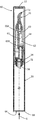
- FIGS. 1 and 2 show the dispenser according to the invention in a sectioned and a non-sectioned representation.
- FIG. 3 shows the dispenser of FIG. 1 prior to the insertion of the container unit into the receiving shaft of the main unit.
- FIGS. 4A to 4C and 5A to 5C show the two coupling members of the coupling device for fastening the container unit to the main unit.
- FIGS. 6A to 6C, 7A to 7C and 8A to 8C show the coupling process for coupling the container unit to the main unit.
- FIGS. 1 and 2 show a liquid dispenser 10 according to the invention in an overall representation.
- the liquid dispenser 10 has basically a rod shape and is from the outside, with the exception of the applicator 70 and the actuating handle 64 , outwardly basically rotationally symmetric in form.
- FIG. 2 in which the liquid dispenser 10 is shown in a sectional representation and with a mounted cap 12 , the individual components are described.
- the liquid dispenser 10 possesses a main unit 60 having a grip 61 , on which the actuating handle 64 is provided. This actuating handle 64 is disposed in an aperture 63 in the grip 61 and bounds a pumping chamber 65 of a pumping device 62 .
- a pressure relief valve 65 A which is provided between the pumping chamber 65 and a liquid store 24 , opens, so that, under the impact of the expansion of the pumping chamber 65 , this is filled up with liquid from the liquid store 24 .
- the liquid store 24 is part of a container unit 20 , which on the end facing away from the discharge opening 72 is inserted in a receiving shaft 66 of the main unit 60 .
- the container unit 20 is set back from a rim 68 which circumferentially surrounds an opening of the receiving shaft 66 .
- the container unit 20 protrudes from the rim 68 by 5 mm or less, preferably by 2 mm or less, in particular preferably by 1 mm or less.
- the container unit 20 possesses a coupling member 32 , which is described in greater detail further below and which, in the state of FIG. 2 , is connected to a coupling member 34 belonging to the main unit.
- FIG. 3 shows the main unit 60 and the container unit 20 in separated representation. It can be seen that the container unit 20 consists of two elements, namely an end-closed sleeve element 21 , which defines the volume of the liquid store 24 , and a thereon mounted element 23 , which provides the coupling member 32 .
- the essential components of the main unit 60 have already previously been described. Reference is therefore made only to the coupling member 34 belonging to the main unit, which possesses an opening sleeve 56 provided with a cutting tip, which in the designated manner, upon the insertion of the container unit 20 , pierces the membrane 26 .
- the two coupling members 32 , 34 are described once again below with reference to FIGS. 4A to 4C and 5A to 5C .
- FIG. 4A to 4C show the coupling member 34 belonging to the main unit.
- This has a comparatively simple structure.
- An outer sleeve 51 possesses on the end face a gearing-like ramp structure 53 having a total of 12 teeth 52 , which are arranged in the manner of a spur gearing and respectively possess two individual ramps 54 .
- said opening sleeve 56 which, in the designated manner, is provided to open said membrane and is configured as a hollow tube, in order to be able to convey liquid from the liquid store 24 .
- two retaining cams 50 point, on opposite sides, away from the opening sleeve 56 .
- the coupling member 34 additionally possess a fixing region 58 on an element 57 for the fitting of a metallic helical spring 55 .
- the coupling member 32 represented in FIG. 5A to 5C , on sides of the container unit 20 likewise possesses along its outer periphery a gearing-like ramp structure 43 including ramps 44 .
- a gearing-like ramp structure 43 including ramps 44 .
- an inner sleeve 47 Surrounded by this ramp structure 43 is an inner sleeve 47 , wherein between the ramp structure 43 and the inner sleeve 47 is provided a guide structure 46 for receiving said helical spring 55 .
- the retaining structure 40 comprises respectively six gaps 41 and six stop faces 42 , wherein sliding surfaces 45 are respectively provided between the gaps 41 and the stop faces 42 .
- the joining of the coupling devices 30 consisting of the two coupling members 32 , 34 is illustrated with reference to FIG. 6A to 8C .
- FIG. 6A to 6C show a first phase, in the course of which the container unit 20 is inserted into the receiving shaft 66 in the direction of the arrow 6 .
- the opening sleeve 56 is slid into the outlet opening 22 of the container unit 20 and pierces the membrane 26 .
- the helical spring 55 enters the guide structure 46 provided for this purpose, until, in the state of FIG. 6A to 6C , it reaches the bottom thereof, so that a continued movement of the container unit 20 is made in the direction of the coupling member 34 against the force of this helical spring.
- the retaining cams 50 Shortly after the membrane has been pierced by the opening sleeve 56 , the retaining cams 50 enter the sleeve 47 and are brought by the lead-in structure 48 into one of six possible defined rotation settings, wherein, for this purpose, the container unit 20 and the main unit 60 as a whole change to a small extent their relative rotation setting.
- the ramp structures 43 , 53 from the setting of FIG. 7A to 7C , enter into engagement with one another.
- a further rotation of the main unit 60 and the container unit 20 relative to one another ensues, until the state of FIG. 8A to 8C , in which a desired rotational relative setting between the main unit 60 and the container unit 20 is obtained, is reached.
- the retaining cams 50 are oriented in alignment with sliding surfaces 45 of the coupling member 32 , which sliding surfaces 45 are of the kind which are oriented sloping in the direction of the stop faces 42 .
Applications Claiming Priority (4)
| Application Number | Priority Date | Filing Date | Title |
|---|---|---|---|
| EP16182018 | 2016-07-29 | ||
| EP16182018.8 | 2016-07-29 | ||
| EP16182018.8A EP3275556B1 (de) | 2016-07-29 | 2016-07-29 | Flüssigkeitsspender |
| PCT/EP2017/067773 WO2018019607A1 (de) | 2016-07-29 | 2017-07-13 | Flüssigkeitsspender |
Publications (2)
| Publication Number | Publication Date |
|---|---|
| US20190307228A1 US20190307228A1 (en) | 2019-10-10 |
| US10835014B2 true US10835014B2 (en) | 2020-11-17 |
Family
ID=56557591
Family Applications (1)
| Application Number | Title | Priority Date | Filing Date |
|---|---|---|---|
| US16/315,489 Active 2037-08-15 US10835014B2 (en) | 2016-07-29 | 2017-07-13 | Liquid dispenser |
Country Status (6)
| Country | Link |
|---|---|
| US (1) | US10835014B2 (de) |
| EP (1) | EP3275556B1 (de) |
| KR (1) | KR102315511B1 (de) |
| CN (1) | CN109475892B (de) |
| ES (1) | ES2765860T3 (de) |
| WO (1) | WO2018019607A1 (de) |
Cited By (2)
| Publication number | Priority date | Publication date | Assignee | Title |
|---|---|---|---|---|
| FR3122651A1 (fr) * | 2021-05-10 | 2022-11-11 | Aptar France Sas | Distributeur de produit fluide |
| FR3122650A1 (fr) * | 2021-05-10 | 2022-11-11 | Aptar France Sas | Distributeur de produit fluide |
Families Citing this family (6)
| Publication number | Priority date | Publication date | Assignee | Title |
|---|---|---|---|---|
| FR3052989B1 (fr) * | 2016-06-27 | 2020-02-21 | Aptar France Sas | Ensemble de distribution et d'application de produit fluide |
| EP3507213A4 (de) * | 2016-09-04 | 2020-04-01 | 9769633 Canada Inc. | Pillenspender |
| US10980332B2 (en) * | 2018-03-29 | 2021-04-20 | Mitsubishi Pencil Company, Limited | Cosmetic applicator |
| CN110236286B (zh) * | 2019-05-23 | 2023-04-21 | 大力新科技(江苏)有限公司 | 一种液体眼影笔 |
| CN110236285A (zh) * | 2019-05-23 | 2019-09-17 | 乐伊嘉 | 一种化妆笔 |
| GB2586015A (en) * | 2019-07-25 | 2021-02-03 | Beldi London Ltd | A Fluid Dispenser |
Citations (13)
| Publication number | Priority date | Publication date | Assignee | Title |
|---|---|---|---|---|
| EP1581436B1 (de) | 2002-11-11 | 2006-07-12 | SIG Technology Ltd. | Garantie-scharnierverschluss für folienversiegelte flaschen und behälter von fliessfähigen inhalten |
| KR20070019939A (ko) | 2003-09-02 | 2007-02-16 | 오쓰까 세이야꾸 가부시키가이샤 | 토출 부재, 그것을 구비하는 토출 용기 및 점안 용기 |
| US7314329B1 (en) * | 2006-07-20 | 2008-01-01 | Young-Kwang Byun | Cosmetics case |
| JP2010012365A (ja) | 2008-06-30 | 2010-01-21 | Yoshino Kogyosho Co Ltd | 液体噴出器 |
| JP2010235196A (ja) | 2009-03-31 | 2010-10-21 | Yoshino Kogyosho Co Ltd | 蓄圧式吐出容器 |
| EP2181932B1 (de) | 2008-11-04 | 2012-02-22 | AptarGroup, Inc | Verschluss mit drehbarem Ausgiesser zum Durchstossen einer Membran |
| US8177452B2 (en) * | 2009-04-08 | 2012-05-15 | Yi Li Tsai | Nail polish container |
| WO2012129318A2 (en) | 2011-03-21 | 2012-09-27 | Breathable Foods, Inc. | Selectively dispensing sprays |
| DE102011007405A1 (de) | 2011-04-14 | 2012-10-18 | Ing. Erich Pfeiffer Gmbh | Kosmetik-Spender |
| WO2015003762A1 (de) | 2013-07-09 | 2015-01-15 | Gerhard Brugger | Dosierspender für das austragen eines insbesondere pastösen oder viskosen materials, wie etwa kosmetikcremes, klebemittel und dergleichen |
| WO2015070935A1 (de) | 2013-11-12 | 2015-05-21 | Gerhard Brugger | Dosierspender für das austragen eines insbesondere pastösen oder viskosen materials, wie etwa kosmetikcremes, klebemittel und dergleichen |
| WO2015128572A2 (fr) | 2014-02-28 | 2015-09-03 | Parfums Christian Dior | Dispositif de conditionnement d'une recharge d'un produit |
| WO2016009192A1 (en) | 2014-07-14 | 2016-01-21 | Rieke Packaging Systems Limited | Pump dispensers |
Family Cites Families (1)
| Publication number | Priority date | Publication date | Assignee | Title |
|---|---|---|---|---|
| KR200441175Y1 (ko) * | 2006-11-09 | 2008-07-28 | (주)아모레퍼시픽 | 화장품 용기 뚜껑 체결구조 |
-
2016
- 2016-07-29 ES ES16182018T patent/ES2765860T3/es active Active
- 2016-07-29 EP EP16182018.8A patent/EP3275556B1/de active Active
-
2017
- 2017-07-13 US US16/315,489 patent/US10835014B2/en active Active
- 2017-07-13 WO PCT/EP2017/067773 patent/WO2018019607A1/de active Application Filing
- 2017-07-13 CN CN201780047256.XA patent/CN109475892B/zh active Active
- 2017-07-13 KR KR1020197005740A patent/KR102315511B1/ko active IP Right Grant
Patent Citations (19)
| Publication number | Priority date | Publication date | Assignee | Title |
|---|---|---|---|---|
| EP1581436B1 (de) | 2002-11-11 | 2006-07-12 | SIG Technology Ltd. | Garantie-scharnierverschluss für folienversiegelte flaschen und behälter von fliessfähigen inhalten |
| US7163127B2 (en) | 2002-11-11 | 2007-01-16 | Sig Technology Ltd. | Tamper-proof hinged closure for film-sealed bottles and containers filled with pourable contents |
| KR20070019939A (ko) | 2003-09-02 | 2007-02-16 | 오쓰까 세이야꾸 가부시키가이샤 | 토출 부재, 그것을 구비하는 토출 용기 및 점안 용기 |
| US8007480B2 (en) | 2003-09-02 | 2011-08-30 | Otsuka Pharmaceutical Co., Ltd. | Delivery device, delivery container, and eye dropper provided with the same |
| US7314329B1 (en) * | 2006-07-20 | 2008-01-01 | Young-Kwang Byun | Cosmetics case |
| JP2010012365A (ja) | 2008-06-30 | 2010-01-21 | Yoshino Kogyosho Co Ltd | 液体噴出器 |
| EP2181932B1 (de) | 2008-11-04 | 2012-02-22 | AptarGroup, Inc | Verschluss mit drehbarem Ausgiesser zum Durchstossen einer Membran |
| JP2010235196A (ja) | 2009-03-31 | 2010-10-21 | Yoshino Kogyosho Co Ltd | 蓄圧式吐出容器 |
| US8177452B2 (en) * | 2009-04-08 | 2012-05-15 | Yi Li Tsai | Nail polish container |
| WO2012129318A2 (en) | 2011-03-21 | 2012-09-27 | Breathable Foods, Inc. | Selectively dispensing sprays |
| DE102011007405A1 (de) | 2011-04-14 | 2012-10-18 | Ing. Erich Pfeiffer Gmbh | Kosmetik-Spender |
| US9629438B2 (en) | 2011-04-14 | 2017-04-25 | Aptar Radolfzell Gmbh | Cosmetic dispenser |
| WO2015003762A1 (de) | 2013-07-09 | 2015-01-15 | Gerhard Brugger | Dosierspender für das austragen eines insbesondere pastösen oder viskosen materials, wie etwa kosmetikcremes, klebemittel und dergleichen |
| US20160144395A1 (en) | 2013-07-09 | 2016-05-26 | Gerhard Brugger | Metering dispenser for discharging an in particular pasty or viscous material, such as cosmetic cream, adhesive, and the like |
| WO2015070935A1 (de) | 2013-11-12 | 2015-05-21 | Gerhard Brugger | Dosierspender für das austragen eines insbesondere pastösen oder viskosen materials, wie etwa kosmetikcremes, klebemittel und dergleichen |
| US10046348B2 (en) | 2013-11-12 | 2018-08-14 | Gerhard Brugger | Metering dispenser for discharging an in particular pasty or viscous material, such as cosmetic creams, adhesives and the like |
| WO2015128572A2 (fr) | 2014-02-28 | 2015-09-03 | Parfums Christian Dior | Dispositif de conditionnement d'une recharge d'un produit |
| US9861177B2 (en) | 2014-02-28 | 2018-01-09 | Parfums Christian Dior | Packaging device for packaging a fluid refill |
| WO2016009192A1 (en) | 2014-07-14 | 2016-01-21 | Rieke Packaging Systems Limited | Pump dispensers |
Non-Patent Citations (3)
| Title |
|---|
| International Search Report issued in Application No. PCT/EP2017/067773 dated Oct. 6, 2017 and English translation (7 pages). |
| Korean Office Action issued in corresponding Korean Patent Application No. 10-2019-7005740 dated Aug. 21, 2020 (7 pages). |
| Written Opinion issued in Application No. PCT/EP2017/067773 dated Oct. 6, 2017 (5 pages). |
Cited By (4)
| Publication number | Priority date | Publication date | Assignee | Title |
|---|---|---|---|---|
| FR3122651A1 (fr) * | 2021-05-10 | 2022-11-11 | Aptar France Sas | Distributeur de produit fluide |
| FR3122650A1 (fr) * | 2021-05-10 | 2022-11-11 | Aptar France Sas | Distributeur de produit fluide |
| WO2022238647A1 (fr) * | 2021-05-10 | 2022-11-17 | Aptar France Sas | Distributeur de produit fluide |
| WO2022238648A1 (fr) | 2021-05-10 | 2022-11-17 | Aptar France Sas | Distributeur de produit fluide |
Also Published As
| Publication number | Publication date |
|---|---|
| KR20190035802A (ko) | 2019-04-03 |
| EP3275556B1 (de) | 2019-10-16 |
| ES2765860T3 (es) | 2020-06-11 |
| EP3275556A1 (de) | 2018-01-31 |
| US20190307228A1 (en) | 2019-10-10 |
| CN109475892A (zh) | 2019-03-15 |
| CN109475892B (zh) | 2022-01-07 |
| KR102315511B1 (ko) | 2021-10-20 |
| WO2018019607A1 (de) | 2018-02-01 |
Similar Documents
| Publication | Publication Date | Title |
|---|---|---|
| US10835014B2 (en) | Liquid dispenser | |
| US9161604B2 (en) | Pen dispensers with cartridges and interchangeable tip applicators | |
| US11547807B2 (en) | Delivery device | |
| KR100821447B1 (ko) | 도포용 충전물 압출용기 | |
| US20170265624A1 (en) | Airless cosmetics dispenser | |
| US9707052B2 (en) | Mechanical pen with improvements for pen removably retaining single use capsule containing tooth whitening compounds, dental bonding compounds and adhesives and removably retaining disposable tooth whitening applicators, disposable dental bonding compound applicators and disposable adhesive applicators | |
| JP6042421B2 (ja) | 液体製品ディスペンサ | |
| CN105722604B (zh) | 排放诸如美容霜、粘合剂等尤其糊状或粘性材料的计量分配器 | |
| US9572646B2 (en) | Electrical pen with improvements for pen removably retaining single use cartridge containing tooth whitening compounds, dental bonding compounds, nail polish, and adhesives and removably retaining disposable tooth whitening applicators, disposable dental bonding compound applicators, nail polish applicators and disposable adhesive applicators | |
| US20180064882A1 (en) | Dispensing device with drive mechanism having converging ramps | |
| US8985394B1 (en) | Pen removably retaining single use capsule containing tooth whitening compounds, dental bonding compounds and adhesives and removably retaining disposable tooth whitening applicators, disposable dental bonding compound applicators and disposable adhesive applicators | |
| WO2011095763A1 (en) | Personal care dispenser | |
| KR200469855Y1 (ko) | 스포이드 결합형 분말 혼합 화장용기 | |
| US4308977A (en) | Dispensing device with one-hand operation for pasty substances | |
| KR20180096603A (ko) | 물질 분배기/도포기 | |
| US8172812B2 (en) | Syringe for the metered delivery of materials, in particular of dental materials | |
| US7878374B2 (en) | Fluid product dispenser | |
| US20170225191A1 (en) | Rotary dispenser for multiple cartridge | |
| WO2019115811A1 (en) | Dispensing head for a cosmetic product, associated device and associated application method | |
| KR200468389Y1 (ko) | 화장품 내용물 배출용기 | |
| AU2009100610A4 (en) | Pharmaceuticals or cosmetics combination dispenser | |
| JP5825992B2 (ja) | 移動体繰出容器 | |
| US20110250003A1 (en) | Double type cosmetics package | |
| SK6749Y1 (sk) | Cukrárska zdobiaca ceruzka | |
| CN111885943A (zh) | 具有汲取管的粉末分配器 |
Legal Events
| Date | Code | Title | Description |
|---|---|---|---|
| FEPP | Fee payment procedure |
Free format text: ENTITY STATUS SET TO UNDISCOUNTED (ORIGINAL EVENT CODE: BIG.); ENTITY STATUS OF PATENT OWNER: LARGE ENTITY |
|
| AS | Assignment |
Owner name: APTAR RADOLFZELL GMBH, GERMANY Free format text: ASSIGNMENT OF ASSIGNORS INTEREST;ASSIGNOR:BAUMANN, TOBIAS;REEL/FRAME:047914/0177 Effective date: 20181212 |
|
| STPP | Information on status: patent application and granting procedure in general |
Free format text: DOCKETED NEW CASE - READY FOR EXAMINATION |
|
| STPP | Information on status: patent application and granting procedure in general |
Free format text: NON FINAL ACTION MAILED |
|
| STPP | Information on status: patent application and granting procedure in general |
Free format text: RESPONSE TO NON-FINAL OFFICE ACTION ENTERED AND FORWARDED TO EXAMINER |
|
| STPP | Information on status: patent application and granting procedure in general |
Free format text: PUBLICATIONS -- ISSUE FEE PAYMENT RECEIVED |
|
| STPP | Information on status: patent application and granting procedure in general |
Free format text: PUBLICATIONS -- ISSUE FEE PAYMENT VERIFIED |
|
| STCF | Information on status: patent grant |
Free format text: PATENTED CASE |