US10821860B2 - Seat device - Google Patents
Seat device Download PDFInfo
- Publication number
- US10821860B2 US10821860B2 US16/217,638 US201816217638A US10821860B2 US 10821860 B2 US10821860 B2 US 10821860B2 US 201816217638 A US201816217638 A US 201816217638A US 10821860 B2 US10821860 B2 US 10821860B2
- Authority
- US
- United States
- Prior art keywords
- seatback
- attachment point
- frame
- attachment
- seat
- Prior art date
- Legal status (The legal status is an assumption and is not a legal conclusion. Google has not performed a legal analysis and makes no representation as to the accuracy of the status listed.)
- Expired - Fee Related, expires
Links
- 239000011347 resin Substances 0.000 claims description 20
- 229920005989 resin Polymers 0.000 claims description 20
- 230000030279 gene silencing Effects 0.000 claims description 11
- 230000000694 effects Effects 0.000 description 16
- 238000002474 experimental method Methods 0.000 description 15
- 230000001105 regulatory effect Effects 0.000 description 5
- 230000004043 responsiveness Effects 0.000 description 5
- 229910052751 metal Inorganic materials 0.000 description 3
- 239000002184 metal Substances 0.000 description 3
- 238000004806 packaging method and process Methods 0.000 description 3
- XEEYBQQBJWHFJM-UHFFFAOYSA-N Iron Chemical compound [Fe] XEEYBQQBJWHFJM-UHFFFAOYSA-N 0.000 description 2
- 230000008901 benefit Effects 0.000 description 2
- 238000013016 damping Methods 0.000 description 2
- 238000004519 manufacturing process Methods 0.000 description 2
- 229910000838 Al alloy Inorganic materials 0.000 description 1
- 229910000640 Fe alloy Inorganic materials 0.000 description 1
- 229910052782 aluminium Inorganic materials 0.000 description 1
- XAGFODPZIPBFFR-UHFFFAOYSA-N aluminium Chemical compound [Al] XAGFODPZIPBFFR-UHFFFAOYSA-N 0.000 description 1
- -1 for example Substances 0.000 description 1
- 229910052742 iron Inorganic materials 0.000 description 1
- 238000005304 joining Methods 0.000 description 1
- 238000000034 method Methods 0.000 description 1
- 238000012986 modification Methods 0.000 description 1
- 230000004048 modification Effects 0.000 description 1
- 230000003014 reinforcing effect Effects 0.000 description 1
- 230000035939 shock Effects 0.000 description 1
- 238000003466 welding Methods 0.000 description 1
Images


Classifications
-
- B—PERFORMING OPERATIONS; TRANSPORTING
- B60—VEHICLES IN GENERAL
- B60N—SEATS SPECIALLY ADAPTED FOR VEHICLES; VEHICLE PASSENGER ACCOMMODATION NOT OTHERWISE PROVIDED FOR
- B60N2/00—Seats specially adapted for vehicles; Arrangement or mounting of seats in vehicles
- B60N2/68—Seat frames
- B60N2/682—Joining means
-
- B—PERFORMING OPERATIONS; TRANSPORTING
- B60—VEHICLES IN GENERAL
- B60N—SEATS SPECIALLY ADAPTED FOR VEHICLES; VEHICLE PASSENGER ACCOMMODATION NOT OTHERWISE PROVIDED FOR
- B60N2/00—Seats specially adapted for vehicles; Arrangement or mounting of seats in vehicles
- B60N2/24—Seats specially adapted for vehicles; Arrangement or mounting of seats in vehicles for particular purposes or particular vehicles
- B60N2/42—Seats specially adapted for vehicles; Arrangement or mounting of seats in vehicles for particular purposes or particular vehicles the seat constructed to protect the occupant from the effect of abnormal g-forces, e.g. crash or safety seats
- B60N2/433—Safety locks for back-rests, e.g. with locking bars activated by inertia
-
- B—PERFORMING OPERATIONS; TRANSPORTING
- B60—VEHICLES IN GENERAL
- B60N—SEATS SPECIALLY ADAPTED FOR VEHICLES; VEHICLE PASSENGER ACCOMMODATION NOT OTHERWISE PROVIDED FOR
- B60N2/00—Seats specially adapted for vehicles; Arrangement or mounting of seats in vehicles
- B60N2/02—Seats specially adapted for vehicles; Arrangement or mounting of seats in vehicles the seat or part thereof being movable, e.g. adjustable
- B60N2/20—Seats specially adapted for vehicles; Arrangement or mounting of seats in vehicles the seat or part thereof being movable, e.g. adjustable the back-rest being tiltable, e.g. to permit easy access
-
- B—PERFORMING OPERATIONS; TRANSPORTING
- B60—VEHICLES IN GENERAL
- B60N—SEATS SPECIALLY ADAPTED FOR VEHICLES; VEHICLE PASSENGER ACCOMMODATION NOT OTHERWISE PROVIDED FOR
- B60N2/00—Seats specially adapted for vehicles; Arrangement or mounting of seats in vehicles
- B60N2/02—Seats specially adapted for vehicles; Arrangement or mounting of seats in vehicles the seat or part thereof being movable, e.g. adjustable
- B60N2/22—Seats specially adapted for vehicles; Arrangement or mounting of seats in vehicles the seat or part thereof being movable, e.g. adjustable the back-rest being adjustable
-
- B—PERFORMING OPERATIONS; TRANSPORTING
- B60—VEHICLES IN GENERAL
- B60N—SEATS SPECIALLY ADAPTED FOR VEHICLES; VEHICLE PASSENGER ACCOMMODATION NOT OTHERWISE PROVIDED FOR
- B60N2/00—Seats specially adapted for vehicles; Arrangement or mounting of seats in vehicles
- B60N2/24—Seats specially adapted for vehicles; Arrangement or mounting of seats in vehicles for particular purposes or particular vehicles
- B60N2/42—Seats specially adapted for vehicles; Arrangement or mounting of seats in vehicles for particular purposes or particular vehicles the seat constructed to protect the occupant from the effect of abnormal g-forces, e.g. crash or safety seats
- B60N2/427—Seats or parts thereof displaced during a crash
- B60N2/42709—Seats or parts thereof displaced during a crash involving residual deformation or fracture of the structure
-
- B—PERFORMING OPERATIONS; TRANSPORTING
- B60—VEHICLES IN GENERAL
- B60N—SEATS SPECIALLY ADAPTED FOR VEHICLES; VEHICLE PASSENGER ACCOMMODATION NOT OTHERWISE PROVIDED FOR
- B60N2/00—Seats specially adapted for vehicles; Arrangement or mounting of seats in vehicles
- B60N2/50—Seat suspension devices
- B60N2/502—Seat suspension devices attached to the base of the seat
-
- B—PERFORMING OPERATIONS; TRANSPORTING
- B60—VEHICLES IN GENERAL
- B60N—SEATS SPECIALLY ADAPTED FOR VEHICLES; VEHICLE PASSENGER ACCOMMODATION NOT OTHERWISE PROVIDED FOR
- B60N2/00—Seats specially adapted for vehicles; Arrangement or mounting of seats in vehicles
- B60N2/24—Seats specially adapted for vehicles; Arrangement or mounting of seats in vehicles for particular purposes or particular vehicles
- B60N2/42—Seats specially adapted for vehicles; Arrangement or mounting of seats in vehicles for particular purposes or particular vehicles the seat constructed to protect the occupant from the effect of abnormal g-forces, e.g. crash or safety seats
- B60N2/4207—Seats specially adapted for vehicles; Arrangement or mounting of seats in vehicles for particular purposes or particular vehicles the seat constructed to protect the occupant from the effect of abnormal g-forces, e.g. crash or safety seats characterised by the direction of the g-forces
- B60N2/4214—Seats specially adapted for vehicles; Arrangement or mounting of seats in vehicles for particular purposes or particular vehicles the seat constructed to protect the occupant from the effect of abnormal g-forces, e.g. crash or safety seats characterised by the direction of the g-forces longitudinal
- B60N2/4228—Seats specially adapted for vehicles; Arrangement or mounting of seats in vehicles for particular purposes or particular vehicles the seat constructed to protect the occupant from the effect of abnormal g-forces, e.g. crash or safety seats characterised by the direction of the g-forces longitudinal due to impact coming from the rear
Definitions
- the present invention relates to seat devices and, in particular, to seat devices suitable for seats of, for example, vehicles (such as cars (vehicles on wheels), planes, and ships), where such seat is adapted to be installed in an area that easily vibrates or oscillates.
- vehicles such as cars (vehicles on wheels), planes, and ships
- a seat device described in Japanese Laid-Open Patent Publication No. 2013-067281 is aimed at providing a shock absorbing seat for a vehicle capable of stably relieving impact load with a simple structure and capable of improving the rigidity when a seatback is biased toward, for example, the back of the vehicle.
- the seat device described in Japanese Laid-Open Patent Publication No. 2013-067281 includes a regulating plate extending across a weakened portion of at least one of a base bracket and a movable bracket.
- the regulating plate has a long hole.
- the bracket to which the regulating plate is secured includes an engaging projection fitted in the long hole.
- a seat device described in Japanese Laid-Open Patent Publication No. 2015-044541 is aimed at reducing concentration of a load input to a seatback frame on a fastening point of the seatback frame fastened to a joining member upon rear-end collision of a vehicle.
- the seat device described in Japanese Laid-Open Patent Publication No. 2015-044541 includes a patch formed on a seatback frame and a collar integrated with the patch.
- a stepped portion of a bolt is fitted in the collar to restrict the relative movement of the collar (patch) with respect to an upper arm.
- a patch flange portion receives a lower flange portion of the seatback frame when the lower flange portion moves relative to the upper arm. The patch restricts the relative movement of the seatback frame with respect to the upper arm in this manner, and the load input to the seatback frame is input to the patch.
- the seat device described in Japanese Laid-Open Patent Publication No. 2013-067281 has the long hole in the regulating plate and includes the engaging projection on the bracket.
- the engaging projection is fitted in the long hole, and the regulating plate is secured to the bracket.
- the long hole allows only the vertical movement of the engaging projection, and thus a load applied to the seat in, for example, the longitudinal directions of the vehicle cannot be dispersed.
- a reclining mechanism is secured to the inner surface of a hinge bracket in the width direction of the seat.
- a load applied to the seat in, for example, the width direction cannot be dispersed.
- a seat foot portion of the seat device may be floated by an intervening elastic member such as rubber.
- the seat foot portion includes many parts supporting a seat cushion, the seatback, and the like, and the increased shared load applied to the seat foot portion when a load is applied to the seat may be too high for the strength of the floating portion.
- the height of the hip point increases when the seat foot portion is in the floating state.
- the layout of the floating portion cannot be configured easily due to the effects of, for example, packaging constraints.
- the present invention has been devised taking into consideration the aforementioned problems, and has the object of providing a seat device capable of reducing shared load applied to a floating structure, effects on the layout of the floating structure, and vibration transmitted to a seat by attaching the floating structure to an attachment point connecting a seat cushion and a seatback instead of a typical attachment point connecting the seat and a rail.
- a seat device includes a seat foot frame, a seat cushion frame attached to the seat foot frame, and a seatback frame attached to the seat cushion frame via a seatback attachment member.
- the seatback attachment member includes a first attachment point to which the seat cushion frame extending forward is attached, a second attachment point to which a rear portion of the seat cushion frame is attached, and a third attachment point to which a lower portion of the seatback frame is rotatably attached.
- the second attachment point has a floating structure.
- the first attachment point supports the seat cushion frame and the seatback frame.
- the shared load applied on the first attachment point increases when a load is applied to the seat device in the width direction.
- the third attachment point constitutes a spindle rotating the seatback frame with respect to the seat cushion frame.
- the shared load applied on the third attachment point is less than the shared load applied on the first attachment point.
- Providing the floating structure for the seat foot frame increases the height of the hip point.
- providing the floating structure for the second attachment point does not cause changes in the height of the hip point. Consequently, the seat device is not affected by packaging constraints.
- the layout of the floating structure can easily be configured, leading to an increase in design flexibility.
- the floating structure may include an opening in the second attachment point of the seatback attachment member, a hole portion in which a fastening bolt secured to the seat cushion frame is fitted; and an elastic member disposed between the opening and the hole portion.
- the floating structure having a bush structure reduces vibration of, for example, 24 Hz or higher generated in the seat device to a level as low as the vibration of a structure using an existing dynamic damper in a case where a load is applied to the seat device in, for example, the width direction.
- the seat structure can be simplified and lightened.
- the elastic member may have a plurality of through-holes.
- the through-holes that is, bores in the elastic member reduce vibration of, for example, 20 Hz or higher generated in the seat device compared with the existing dynamic damper. The effects of reducing vibration can be increased by only creating the plurality of through-holes in the elastic member of the bush structure.
- the seat device may further include a collar member in which the fastening bolt is fitted, and a gap or spacing larger than a thickness of the seatback attachment member at the second attachment point may be left between a flange of the collar member and a head of the fastening bolt.
- the bush structure reduces the eigenvalues of the seat device and prevents resonance with the torsional vibration of the body. Furthermore, adding the backlash element (vibration damping property) to reduce the responsiveness increases the effects of reducing vibration of the seat device.
- the backlash element provided for the floating structure reduces the eigenvalues of the seat device and, furthermore, reduces the responsiveness.
- a silencing member may be disposed between the flange of the collar member and the head of the fastening bolt.
- the silencing member may include a resin washer and a resin collar member attached between the head of the fastening bolt and the collar member ( 60 a ), and a gap larger than the thickness of the seatback attachment member at the second attachment point may be left between the resin washer and a flange of the resin collar member.
- the backlash element provided for the bush structure may produce sound that might be recognized as unusual noise when coming into contact with the second attachment point.
- the silencing member provided for the backlash element prevents production of such sound, that is, generation of such unusual noise.
- the seat device is capable of reducing the shared load applied to the floating structure, effects on the layout of the floating structure, and vibration transmitted to the seat by attaching the floating structure to the attachment point connecting the seat cushion and the seatback instead of a typical attachment point connecting the seat and a rail.
- FIG. 1 is a perspective view illustrating a part of a seat device according to this embodiment
- FIG. 2A is a front view illustrating a seatback attachment member
- FIG. 2B is an enlarged front view illustrating a second attachment point of the seatback attachment member
- FIG. 3 is a cross-sectional view taken along line III-III in FIG. 2B ;
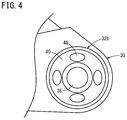
- FIG. 4 is a front view illustrating an example of an elastic member with a plurality of through-holes created in the second attachment point of the seatback attachment member;
- FIGS. 5A and 5B are graphs illustrating results of a first example experiment and a second example experiment, respectively, on effects of reducing vibration using a first example structure, a second example structure, and a reference structure of the seatback attachment member;
- FIG. 6A is a cross-sectional view illustrating a third example structure of the seatback attachment member
- FIG. 6B is a cross-sectional view taken along line VIB-VIB in FIG. 6A ;
- FIGS. 7A and 7B are graphs illustrating results of a third example experiment and a fourth example experiment, respectively, on effects of reducing vibration using the third example structure, a first reference structure, and a second reference structure of the seatback attachment member.
- FIGS. 1 to 7B A preferred embodiment of a seat device according to the present invention will be described in detail below with reference to FIGS. 1 to 7B .
- a seat device 10 includes at least a seat cushion frame 12 , a seatback frame 14 , and seat foot frames 16 installed on the floor or the like of vehicles such as cars (vehicles on wheels), ships, and planes.
- the seat device 10 is installed to be slidable in, for example, the longitudinal direction of a vehicle by the seat foot frames 16 .
- the seat device 10 may be secured to the floor or the like instead of being slidable.
- the seat cushion frame 12 has a frame shape formed of, for example, a left and right pair of cushion side frames 18 extending in the longitudinal direction, a front frame 20 extending between front portions of the cushion side frames 18 , and a rear frame 22 extending between rear portions of the cushion side frames 18 .
- the seat foot frames 16 are attached to the respective cushion side frames 18 .
- the seatback frame 14 has a frame shape formed of a left and right pair of back side frames 24 extending substantially vertically, a lower back frame 26 extending between lower end portions of the left and right back side frames 24 , and a reinforcing pole (not illustrated) extending between upper portions of the back side frames 24 .
- the lower back frame 26 is joined to lower portions of the back side frames 24 by, for example, welding.
- a lower portion of the seatback frame 14 is rotatably attached to a rear portion of the seat cushion frame 12 by seatback attachment members 30 .
- the seatback attachment members 30 are, for example, triangular metal plates or resin plates.
- the seatback attachment members 30 each include a first attachment point 32 a located at a front position, a second attachment point 32 b located at a rear position, and a third attachment point 32 c located at an upper position.
- the seat cushion frame 12 is attached to the first attachment point 32 a of the seatback attachment member 30 , the rear portion of the seat cushion frame 12 is attached to the second attachment point 32 b , and the lower portion of the seatback frame 14 is rotatably attached to the third attachment point 32 c .
- the second attachment point 32 b has a floating structure.
- the floating structure will now be described using three example structures (first to third example structures) with reference to FIGS. 2B to 6B .
- the first example structure includes an opening 34 (see FIG. 3 ) in the second attachment point 32 b of the seatback attachment member 30 , a ring 38 (see FIG. 3 ) composed of metal or resin having a hole portion 36 , and an elastic member 40 (such as rubber) disposed between the inner circumference of the opening 34 and the outer circumference of the ring 38 .
- a fastening bolt 42 (see FIG. 3 ) secured to the seat cushion frame 12 is fitted in the hole portion 36 of the ring 38 .
- the fastening bolt 42 is fitted into, for example, a through-hole 44 of the cushion side frame 18 and secured to the seat cushion frame 12 with a nut 46 screwed onto the fastening bolt 42 from the end.
- the first attachment point 32 a of the seatback attachment member 30 is secured to, for example, the upper portion of the seat cushion frame 12 using a bolt (see FIG. 1 ) or the like, and the second attachment point 32 b of the seatback attachment member 30 is secured to the rear portion of the cushion side frame 18 with the fastening bolt 42 fitted into the hole portion 36 and the nut 46 screwed onto the fastening bolt 42 from the end. Then, the lower portion of the seatback frame 14 is rotatably attached to the third attachment point 32 c of the seatback attachment member 30 .
- the second example structure is substantially similar to the first example structure except for a plurality of through-holes 48 in the elastic member 40 .
- four through-holes 48 are created at regular intervals.
- the number is not limited to four, and may be two, three, or six.
- a large number of through-holes 48 with a diameter of, for example, 2 mm or less may be created.
- the through-holes 48 may have, for example, a circular shape, an elliptical shape, or a shape of a running track.
- the second example structure had four circular through-holes 48 in the elastic member 40 at regular intervals (see FIG. 4 ).
- the reference structure used an existing dynamic damper to reduce vibration.
- the first example structure reduces vibrations of a frequency of 24 Hz or higher to a level as low as the structure using the existing dynamic damper does. It is clear that the second example structure reduces vibrations of a frequency of 18 Hz or higher to a level lower than the first example structure and the structure using the existing dynamic damper do.
- the first example structure reduces vibrations of a frequency of 24 Hz or higher to a level as low as the structure using the existing dynamic damper does. It is clear that the second example structure reduces vibrations of a frequency of 18 Hz or higher to a level lower than the first example structure and the structure using the existing dynamic damper do.
- the third example structure includes a backlash element as the floating structure unlike the first example structure and the second example structure.
- the third example structure includes a first collar member 60 a and a second collar member 60 b .
- the first collar member 60 a is fitted in a through-hole 62 of the second attachment point 32 b of the seatback attachment member 30 , and the fastening bolt 42 is fitted in the first collar member 60 a .
- the first collar member 60 a is preferably composed of metal, for example, iron, iron alloy, aluminum, or aluminum alloy.
- the first collar member 60 a has a shape of which outer diameter changes, for example, in a stepped manner, and includes a first small diameter portion 64 on the outer side (the seatback attachment member 30 side) and a first large diameter portion 66 (flange portion) on the inner side (the cushion side frame 18 side) integrated with each other.
- the diameter da of the first large diameter portion 66 is larger than the diameter db of the through-hole 62 in the vertical direction (see FIG. 6B ), and the diameter dc of the first small diameter portion 64 is smaller than the diameter db of the through-hole 62 in the vertical direction.
- the second collar member 60 b is fitted in the through-hole 62 of the second attachment point 32 b of the seatback attachment member 30 , and the first collar member 60 a is fitted in the second collar member 60 b .
- the second collar member 60 b also has a shape of which outer diameter changes, for example, in a stepped manner, and includes a second small diameter portion 68 on the outer side (the seatback attachment member 30 side) and a second large diameter portion 70 (flange portion) on the inner side (the cushion side frame 18 side) integrated with each other.
- the diameter dd of the second large diameter portion 70 is larger than the diameter db of the through-hole 62 in the vertical direction (see FIG.
- the second collar member 60 b is preferably composed of, for example, resin or rubber preventing noise generated at contact of the cushion side frame 18 .
- a first gap 72 a and a second gap 72 b of about 1 mm each are left between the second collar member 60 b and the through-hole 62 , in particular, in the vertical direction.
- Small gaps of 0.5 mm or less each are left in the longitudinal direction.
- the size of the first gap 72 a and the size of the second gap 72 b may be identical to or different from each other.
- the first gap 72 a and the second gap 72 b facilitate relative vertical movement of the seatback attachment member 30 and the seatback frame 14 with respect to the rear portion of the cushion side frame 18 , resulting in an increase in the effects of reducing the vibration of the seat device 10 . More specifically, providing a backlash element for the floating structure reduces the eigenvalues of the seat device 10 and, furthermore, reduces the responsiveness.
- the first large diameter portion 66 of the first collar member 60 a is always located on the outer side of the rear portion of the cushion side frame 18 and on the inner side of the second collar member 60 b.
- the above-described backlash element includes an annular washer 80 to which an end of the second small diameter portion 68 of the second collar member 60 b is fitted and secured.
- the washer 80 is rectangular in section, and is composed of, for example, resin or rubber as is the second collar member 60 b . That is, the second collar member 60 b and the washer 80 constitute a silencing member.
- the center of the second attachment point 32 b (center of the through-hole 62 ) of the seatback attachment member 30 is located at the center between the inner end surface of the second large diameter portion 70 of the second collar member 60 b and the outer end surface of the washer 80 .
- a third gap 72 c of about 1 mm is left between the outer end surface of the second large diameter portion 70 of the second collar member 60 b and the opposing inner end surface of the rear portion of the seatback attachment member 30 .
- a fourth gap 72 d of about 1 mm is left between the inner end surface of the washer 80 and the opposing outer end surface of the rear portion of the seatback attachment member 30 .
- the first small diameter portion 64 of the first collar member 60 a is fitted into the through-hole of the second collar member 60 b to assemble the second collar member 60 b to the first collar member 60 a .
- the through-hole of the first collar member 60 a and the through-hole 62 of the second attachment point 32 b of the seatback attachment member 30 are positioned, and the fastening bolt 42 is fitted from the outside of the seatback attachment member 30 to the inside. At this moment, the fastening bolt 42 is fitted into the through-hole of the second attachment point 32 b of the seatback attachment member 30 and the through-hole of the first collar member 60 a.
- the rear portion of the cushion side frame 18 is assembled to the inner side of the seatback attachment member 30 .
- the seatback attachment member 30 is moved toward the rear portion of the cushion side frame 18 such that the first small diameter portion 64 of the first collar member 60 a and the second small diameter portion 68 of the second collar member 60 b after assembly are fitted into the through-hole 62 of the rear portion of the seatback attachment member 30 .
- This causes the first small diameter portion 64 of the first collar member 60 a and the second small diameter portion 68 of the second collar member 60 b after assembly to protrude outward from the rear portion of the seatback attachment member 30 .
- the washer 80 is fitted onto the end of the second small diameter portion 68 of the second collar member 60 b.
- the fastening bolt 42 is fitted into the through-hole of the first collar member 60 a , and the nut 46 is screwed onto the end of the fastening bolt 42 protruding from the inner side of the rear portion of the cushion side frame 18 to secure the nut 46 , the first collar member 60 a , the second collar member 60 b , and the washer 80 to the seatback attachment member 30 .
- the third example structure reduces vibrations of a frequency of 19 Hz or higher, in general, to a level as low as or lower than the structure using the existing dynamic damper does. It is clear that, on the fourth track, the third example structure reduces vibrations of a frequency of 15 Hz or higher, in general, to a level lower than the structure using the existing dynamic damper does.
- the seat device 10 includes the seat foot frames 16 , the seat cushion frame 12 attached to the seat foot frames 16 , and the seatback frame 14 attached to the seat cushion frame 12 via the seatback attachment members 30 .
- the seatback attachment members 30 each include the first attachment point 32 a to which the seat cushion frame 12 extending forward is attached, the second attachment point 32 b to which the rear portion of the seat cushion frame 12 is attached, and the third attachment point 32 c to which the lower portion of the seatback frame 14 is rotatably attached.
- the second attachment point 32 b has the floating structure.
- the first attachment point 32 a supports the seat cushion frame 12 and the seatback frame 14 .
- the shared load applied on the first attachment point 32 a increases when a load is applied to the seat device 10 in the width direction.
- the third attachment point 32 c constitutes a spindle that rotates the seatback frame 14 with respect to the seat cushion frame 12 .
- the shared load applied on the third attachment point 32 c is less than the shared load applied on the first attachment point 32 a.
- Providing the floating structure for the seat foot frames 16 increases the height of the hip point.
- providing the floating structure for the second attachment point 32 b does not cause changes in the height of the hip point. Consequently, the seat device 10 is not affected by packaging constraints.
- the layout of the floating structure can easily be configured, leading to an increase in design flexibility.
- the floating structure includes the opening 34 in the second attachment point 32 b of the seatback attachment member 30 , the hole portion 36 in which the fastening bolt 42 secured to the seat cushion frame 12 is fitted, and the elastic member 40 disposed between the opening portion 34 and the hole portion 36 .
- the floating structure having a bush structure reduces vibration of, for example, 24 Hz or higher generated in the seat device 10 to a level as low as the structure using the existing dynamic damper does in a case where a load is applied to the seat device 10 in, for example, the width direction.
- the seat structure can be simplified and lightened.
- the elastic member 40 has the plurality of through-holes 48 .
- the through-holes 48 that is, bores in the elastic member 40 reduce vibration of, for example, 20 Hz or higher generated in the seat device 10 compared with the existing dynamic damper.
- the effects of reducing vibration can be increased by only creating the plurality of through-holes 48 in the elastic member 40 of the bush structure.
- the fastening bolt 42 is fitted in the collar member 60 a , and a gap larger than the thickness of the second attachment point 32 b is left between the flange of the collar member 60 a and the fastening bolt 42 .
- the bush structure reduces the eigenvalues of the seat device 10 and prevents resonance with the torsional vibration of the body. Furthermore, adding the backlash element (vibration damping property) to reduce the responsiveness increases the effects of reducing vibration of the seat device 10 .
- the backlash element provided for the floating structure reduces the eigenvalues of the seat device 10 and, furthermore, reduces the responsiveness.
- the silencing member is disposed between the flange of the collar member 60 a and the fastening bolt 42 .
- the silencing member includes the resin washer 80 disposed between the fastening bolt 42 and the collar member 60 a and the resin collar member 60 b , and a gap or spacing larger than the thickness of the seatback attachment member 30 at the second attachment point 32 b is left between the resin washer 80 and the flange of the resin collar member 60 b , as shown.
- the backlash element provided for the bush structure may produce sound that might be recognized as unusual noise when coming into contact with the second attachment point 32 b .
- the silencing member provided for the backlash element prevents production of such sound, that is, generation of such unusual noise.
Landscapes
- Engineering & Computer Science (AREA)
- Aviation & Aerospace Engineering (AREA)
- Transportation (AREA)
- Mechanical Engineering (AREA)
- Seats For Vehicles (AREA)
- Vibration Prevention Devices (AREA)
Abstract
Description
[4] In the present invention, the seat device may further include a collar member in which the fastening bolt is fitted, and a gap or spacing larger than a thickness of the seatback attachment member at the second attachment point may be left between a flange of the collar member and a head of the fastening bolt.
Claims (6)
Applications Claiming Priority (2)
| Application Number | Priority Date | Filing Date | Title |
|---|---|---|---|
| JP2017-241018 | 2017-12-15 | ||
| JP2017241018A JP6722646B2 (en) | 2017-12-15 | 2017-12-15 | Seat device |
Publications (2)
| Publication Number | Publication Date |
|---|---|
| US20190184866A1 US20190184866A1 (en) | 2019-06-20 |
| US10821860B2 true US10821860B2 (en) | 2020-11-03 |
Family
ID=66815500
Family Applications (1)
| Application Number | Title | Priority Date | Filing Date |
|---|---|---|---|
| US16/217,638 Expired - Fee Related US10821860B2 (en) | 2017-12-15 | 2018-12-12 | Seat device |
Country Status (3)
| Country | Link |
|---|---|
| US (1) | US10821860B2 (en) |
| JP (1) | JP6722646B2 (en) |
| CN (1) | CN109987005B (en) |
Families Citing this family (3)
| Publication number | Priority date | Publication date | Assignee | Title |
|---|---|---|---|---|
| JP6716381B2 (en) * | 2016-07-21 | 2020-07-01 | 株式会社タチエス | Vehicle seat |
| JP6973291B2 (en) * | 2018-05-22 | 2021-11-24 | トヨタ紡織株式会社 | Vehicle seat |
| JP2022191087A (en) * | 2021-06-15 | 2022-12-27 | 株式会社アーケム | Seat pad and manufacturing method of seat pad |
Citations (20)
| Publication number | Priority date | Publication date | Assignee | Title |
|---|---|---|---|---|
| JPS644147U (en) | 1987-06-26 | 1989-01-11 | ||
| US6709053B1 (en) * | 2002-09-30 | 2004-03-23 | Lear Corporation | Vehicle seat assembly with energy managing member |
| JP2006220172A (en) | 2005-02-08 | 2006-08-24 | Kurashiki Kako Co Ltd | Aluminum fitting combined vibration absorber and its manufacturing method |
| WO2008017794A2 (en) * | 2006-08-11 | 2008-02-14 | Faurecia Sièges d'Automobile | Device for energy absorption upon impact for automotive vehicle seat, seat and automotive vehicle comprising the device |
| WO2008149044A2 (en) * | 2007-06-05 | 2008-12-11 | Faurecia Sièges d'Automobile | Energy absorption assembly provided with two absorption devices |
| DE102008022120A1 (en) * | 2008-05-05 | 2009-11-12 | Audi Ag | vehicle seat |
| JP2011079524A (en) | 2011-01-14 | 2011-04-21 | Toyota Motor Corp | Stabilizer device |
| WO2012013371A1 (en) * | 2010-07-28 | 2012-02-02 | Johnson Controls Gmbh | Vehicle seat |
| JP2012096744A (en) | 2010-11-05 | 2012-05-24 | Honda Motor Co Ltd | Vibration reducing structure of vehicle seat |
| WO2012077444A1 (en) * | 2010-12-09 | 2012-06-14 | 日本発條株式会社 | Vehicle seat |
| WO2013042550A1 (en) * | 2011-09-21 | 2013-03-28 | 日本発條株式会社 | Vehicle seat |
| JP2013067281A (en) | 2011-09-22 | 2013-04-18 | Fuji Kiko Co Ltd | Shock absorbing sheet for vehicle |
| FR2998837A1 (en) * | 2012-12-05 | 2014-06-06 | Faurecia Sieges Automobile | JOINT ASSEMBLY FOR VEHICLE SEAT |
| DE102014004440A1 (en) * | 2014-03-27 | 2014-09-18 | Daimler Ag | Seat structure for a vehicle seat, in particular a motor vehicle |
| US20140292054A1 (en) * | 2011-04-04 | 2014-10-02 | Keiper Gmbh & Co. Kg | Component for a vehicle seat |
| JP2015044541A (en) | 2013-08-29 | 2015-03-12 | トヨタ自動車株式会社 | Seat back frame structure |
| DE102014219066A1 (en) * | 2014-09-22 | 2016-03-24 | Johnson Controls Gmbh | Connecting arrangement for a vehicle seat and vehicle seat |
| DE102016203445A1 (en) * | 2016-03-02 | 2017-09-07 | Brose Fahrzeugteile Gmbh & Co. Kg, Coburg | Vehicle seat with at least one signaling means for signaling a deformation at a defined deformation region of the seat frame |
| WO2018215395A1 (en) * | 2017-05-24 | 2018-11-29 | Brose Fahrzeugteile Gmbh & Co. Kommanditgesellschaft, Coburg | Force-absorbing device for a motor vehicle seat |
| US20190217757A1 (en) * | 2018-01-18 | 2019-07-18 | Toyota Boshoku Kabushiki Kaisha | Vehicle seat |
Family Cites Families (5)
| Publication number | Priority date | Publication date | Assignee | Title |
|---|---|---|---|---|
| JPS644147A (en) * | 1987-06-26 | 1989-01-09 | Nec Corp | Call dial correction system for multi-functional telephone set |
| JP2012071641A (en) * | 2010-09-28 | 2012-04-12 | Aisin Seiki Co Ltd | Seat reclining device for vehicle |
| MY165807A (en) * | 2010-10-01 | 2018-04-27 | Nissan Motor | Vehicle seat and stiffness setting method for vehicle seat technical field |
| DE102012013208B4 (en) * | 2012-05-07 | 2019-07-25 | Adient Luxembourg Holding S.À R.L. | Seat part of a vehicle seat |
| CN104853954B (en) * | 2012-11-30 | 2017-03-08 | 提爱思科技股份有限公司 | vehicle seat |
-
2017
- 2017-12-15 JP JP2017241018A patent/JP6722646B2/en not_active Expired - Fee Related
-
2018
- 2018-12-12 US US16/217,638 patent/US10821860B2/en not_active Expired - Fee Related
- 2018-12-14 CN CN201811534256.5A patent/CN109987005B/en not_active Expired - Fee Related
Patent Citations (21)
| Publication number | Priority date | Publication date | Assignee | Title |
|---|---|---|---|---|
| JPS644147U (en) | 1987-06-26 | 1989-01-11 | ||
| US6709053B1 (en) * | 2002-09-30 | 2004-03-23 | Lear Corporation | Vehicle seat assembly with energy managing member |
| JP2006220172A (en) | 2005-02-08 | 2006-08-24 | Kurashiki Kako Co Ltd | Aluminum fitting combined vibration absorber and its manufacturing method |
| WO2008017794A2 (en) * | 2006-08-11 | 2008-02-14 | Faurecia Sièges d'Automobile | Device for energy absorption upon impact for automotive vehicle seat, seat and automotive vehicle comprising the device |
| WO2008149044A2 (en) * | 2007-06-05 | 2008-12-11 | Faurecia Sièges d'Automobile | Energy absorption assembly provided with two absorption devices |
| DE102008022120A1 (en) * | 2008-05-05 | 2009-11-12 | Audi Ag | vehicle seat |
| WO2012013371A1 (en) * | 2010-07-28 | 2012-02-02 | Johnson Controls Gmbh | Vehicle seat |
| JP2012096744A (en) | 2010-11-05 | 2012-05-24 | Honda Motor Co Ltd | Vibration reducing structure of vehicle seat |
| WO2012077444A1 (en) * | 2010-12-09 | 2012-06-14 | 日本発條株式会社 | Vehicle seat |
| JP2011079524A (en) | 2011-01-14 | 2011-04-21 | Toyota Motor Corp | Stabilizer device |
| US20140292054A1 (en) * | 2011-04-04 | 2014-10-02 | Keiper Gmbh & Co. Kg | Component for a vehicle seat |
| WO2013042550A1 (en) * | 2011-09-21 | 2013-03-28 | 日本発條株式会社 | Vehicle seat |
| JP2013067281A (en) | 2011-09-22 | 2013-04-18 | Fuji Kiko Co Ltd | Shock absorbing sheet for vehicle |
| FR2998837A1 (en) * | 2012-12-05 | 2014-06-06 | Faurecia Sieges Automobile | JOINT ASSEMBLY FOR VEHICLE SEAT |
| JP2015044541A (en) | 2013-08-29 | 2015-03-12 | トヨタ自動車株式会社 | Seat back frame structure |
| US20160207425A1 (en) | 2013-08-29 | 2016-07-21 | Toyota Jidosha Kabushiki Kaisha | Seatback frame structure |
| DE102014004440A1 (en) * | 2014-03-27 | 2014-09-18 | Daimler Ag | Seat structure for a vehicle seat, in particular a motor vehicle |
| DE102014219066A1 (en) * | 2014-09-22 | 2016-03-24 | Johnson Controls Gmbh | Connecting arrangement for a vehicle seat and vehicle seat |
| DE102016203445A1 (en) * | 2016-03-02 | 2017-09-07 | Brose Fahrzeugteile Gmbh & Co. Kg, Coburg | Vehicle seat with at least one signaling means for signaling a deformation at a defined deformation region of the seat frame |
| WO2018215395A1 (en) * | 2017-05-24 | 2018-11-29 | Brose Fahrzeugteile Gmbh & Co. Kommanditgesellschaft, Coburg | Force-absorbing device for a motor vehicle seat |
| US20190217757A1 (en) * | 2018-01-18 | 2019-07-18 | Toyota Boshoku Kabushiki Kaisha | Vehicle seat |
Non-Patent Citations (1)
| Title |
|---|
| Office Action dated Jun. 4, 2019 issued over the corresponding Japanese Patent Application No. 2017-241018 with the English machine translation thereof. |
Also Published As
| Publication number | Publication date |
|---|---|
| US20190184866A1 (en) | 2019-06-20 |
| JP6722646B2 (en) | 2020-07-15 |
| CN109987005A (en) | 2019-07-09 |
| JP2019107951A (en) | 2019-07-04 |
| CN109987005B (en) | 2021-06-18 |
Similar Documents
| Publication | Publication Date | Title |
|---|---|---|
| JP6190651B2 (en) | Vibration isolator | |
| US10821860B2 (en) | Seat device | |
| JP2016061425A (en) | Bump stopper cap | |
| JP2017081399A (en) | Car body rear structure | |
| CN110341733B (en) | Floor shock-absorbing structure for rail vehicle and rail vehicle | |
| US10717476B2 (en) | Cab mounting apparatus for commercial vehicle | |
| WO2014007011A1 (en) | Elastic support structure for seat | |
| CN104071234A (en) | Vehicle body structure | |
| US20120025509A1 (en) | Fuel tank mounting structure for vehicle | |
| JP2007100889A (en) | Strut mount | |
| JP2011020550A (en) | Vehicle seat | |
| JPWO2013157134A1 (en) | Vehicle seat | |
| JP2019217889A (en) | Rear vehicle body structure for vehicle | |
| JP2016130056A (en) | Vehicle seat support structure | |
| JP3972592B2 (en) | Damping structure of traction device in railway vehicle | |
| JP2008544179A (en) | Vibration damper especially for mounting on vehicle seats | |
| US8985605B2 (en) | Rear shock absorber mounting structure for vehicle | |
| KR20160063615A (en) | air-spring installation structure for vehicle | |
| JP2001227582A (en) | Vibration control device for automobile | |
| JP3124869U (en) | Automotive cushion spring seat bearing combination device | |
| JP2019209882A (en) | Sub-frame structure | |
| JP2008002565A (en) | Vibration isolator | |
| KR100992815B1 (en) | Car trailing arm mounting units | |
| US10350982B2 (en) | Vehicle body | |
| US20200378428A1 (en) | Connecting clip incorporating a spring structure |
Legal Events
| Date | Code | Title | Description |
|---|---|---|---|
| AS | Assignment |
Owner name: HONDA MOTOR CO., LTD., JAPAN Free format text: ASSIGNMENT OF ASSIGNORS INTEREST;ASSIGNORS:TAMAKI, HIDEKAZU;SATO, TAKUMI;HITOMI, HIDEKI;REEL/FRAME:047755/0892 Effective date: 20181112 |
|
| FEPP | Fee payment procedure |
Free format text: ENTITY STATUS SET TO UNDISCOUNTED (ORIGINAL EVENT CODE: BIG.); ENTITY STATUS OF PATENT OWNER: LARGE ENTITY |
|
| STPP | Information on status: patent application and granting procedure in general |
Free format text: APPLICATION DISPATCHED FROM PREEXAM, NOT YET DOCKETED |
|
| STPP | Information on status: patent application and granting procedure in general |
Free format text: DOCKETED NEW CASE - READY FOR EXAMINATION |
|
| STPP | Information on status: patent application and granting procedure in general |
Free format text: NON FINAL ACTION MAILED |
|
| STPP | Information on status: patent application and granting procedure in general |
Free format text: NOTICE OF ALLOWANCE MAILED -- APPLICATION RECEIVED IN OFFICE OF PUBLICATIONS |
|
| STPP | Information on status: patent application and granting procedure in general |
Free format text: PUBLICATIONS -- ISSUE FEE PAYMENT VERIFIED |
|
| STCF | Information on status: patent grant |
Free format text: PATENTED CASE |
|
| FEPP | Fee payment procedure |
Free format text: MAINTENANCE FEE REMINDER MAILED (ORIGINAL EVENT CODE: REM.); ENTITY STATUS OF PATENT OWNER: LARGE ENTITY |
|
| LAPS | Lapse for failure to pay maintenance fees |
Free format text: PATENT EXPIRED FOR FAILURE TO PAY MAINTENANCE FEES (ORIGINAL EVENT CODE: EXP.); ENTITY STATUS OF PATENT OWNER: LARGE ENTITY |
|
| STCH | Information on status: patent discontinuation |
Free format text: PATENT EXPIRED DUE TO NONPAYMENT OF MAINTENANCE FEES UNDER 37 CFR 1.362 |
|
| FP | Lapsed due to failure to pay maintenance fee |
Effective date: 20241103 |