JP2007100889A - Strut mount - Google Patents
Strut mount Download PDFInfo
- Publication number
- JP2007100889A JP2007100889A JP2005293400A JP2005293400A JP2007100889A JP 2007100889 A JP2007100889 A JP 2007100889A JP 2005293400 A JP2005293400 A JP 2005293400A JP 2005293400 A JP2005293400 A JP 2005293400A JP 2007100889 A JP2007100889 A JP 2007100889A
- Authority
- JP
- Japan
- Prior art keywords
- elastic body
- rubber elastic
- strut mount
- metal fitting
- soft layer
- Prior art date
- Legal status (The legal status is an assumption and is not a legal conclusion. Google has not performed a legal analysis and makes no representation as to the accuracy of the status listed.)
- Granted
Links
- 238000003860 storage Methods 0.000 claims abstract description 42
- 239000006096 absorbing agent Substances 0.000 claims abstract description 19
- 230000035939 shock Effects 0.000 claims abstract description 19
- 239000002184 metal Substances 0.000 claims description 66
- 230000002093 peripheral effect Effects 0.000 claims description 17
- 230000002265 prevention Effects 0.000 claims description 15
- JOYRKODLDBILNP-UHFFFAOYSA-N Ethyl urethane Chemical compound CCOC(N)=O JOYRKODLDBILNP-UHFFFAOYSA-N 0.000 claims description 5
- 239000006261 foam material Substances 0.000 claims description 3
- 238000003780 insertion Methods 0.000 description 5
- 230000037431 insertion Effects 0.000 description 5
- 238000010008 shearing Methods 0.000 description 5
- 239000000725 suspension Substances 0.000 description 5
- 230000002159 abnormal effect Effects 0.000 description 4
- 230000006835 compression Effects 0.000 description 4
- 238000007906 compression Methods 0.000 description 4
- 238000006073 displacement reaction Methods 0.000 description 4
- 238000010521 absorption reaction Methods 0.000 description 2
- 239000000463 material Substances 0.000 description 2
- 230000008094 contradictory effect Effects 0.000 description 1
- 230000006866 deterioration Effects 0.000 description 1
- 230000000694 effects Effects 0.000 description 1
- 239000006260 foam Substances 0.000 description 1
- 238000005187 foaming Methods 0.000 description 1
- 238000004519 manufacturing process Methods 0.000 description 1
- 230000003068 static effect Effects 0.000 description 1
- 239000004575 stone Substances 0.000 description 1
- 238000003260 vortexing Methods 0.000 description 1
- 238000003466 welding Methods 0.000 description 1
Images


Landscapes
- Vehicle Body Suspensions (AREA)
- Fluid-Damping Devices (AREA)
Abstract
Description
本発明は、車両のサスペンション機構を構成するショックアブソーバを車体へマウントするストラットマウントに関する。 The present invention relates to a strut mount for mounting a shock absorber constituting a suspension mechanism of a vehicle on a vehicle body.
自動車等の車両には、ホイールと車体との間にショックアブソーバ等により構成されるストラット型のサスペンション機構が配置されたものがある。ストラット型のサンスペンション機構では、ショックアブソーバがストラットマウントを介して車体へマウントされている。
ストラットマウントの多くは、外側金具の収納部内に、内側金具と一体化されたゴム弾性体を圧入し、収納部の開口部分に配置された脱落防止用の金属製プレートによって、内側金具及びゴム弾性体が外側金具から脱落するのを防止する構成になっている。また、ストラットマウントには、内側金具と一体化されたゴム弾性体を外側金具に対して強固に支持させるために、ゴム弾性体の外周にアウタープレートを取り付け、このアウタープレートを外側金具に圧入させて支持する構成をとっているものが提案されている。このような構成のストラットマウントでは、ゴム弾性体の内周に取り付けた内筒金具に路面からの入力が入り、外周に設けたアウタープレートを介して車体側から外力が伝達されるため、ゴム弾性体には大きな剪断応力が生じ、ゴム弾性体の耐久性の面で問題がある。このような問題に対処するべく、ゴム弾性体と外側金具との間にストッパークッションを介在させて、ゴム弾性体にかかる剪断力を緩和させたものも提案されている(例えば、特許文献1,2参照)。
Most strut mounts press-fit a rubber elastic body that is integrated with the inner metal fitting into the outer metal fitting housing, and a metal plate that prevents the dropout from being placed in the opening of the housing to prevent the inner metal fitting and rubber elastic. It is configured to prevent the body from falling off the outer fitting. In addition, an outer plate is attached to the outer periphery of the rubber elastic body and the outer plate is press-fitted into the outer metal fitting in order to firmly support the rubber elastic body integrated with the inner metal fitting to the outer metal fitting. Have been proposed to support this. In the strut mount having such a configuration, since the input from the road surface enters the inner cylinder fitting attached to the inner periphery of the rubber elastic body, and external force is transmitted from the vehicle body side through the outer plate provided on the outer periphery, the rubber elasticity A large shear stress is generated in the body, and there is a problem in terms of durability of the rubber elastic body. In order to cope with such a problem, there has also been proposed a structure in which a stopper cushion is interposed between the rubber elastic body and the outer metal fitting to reduce the shearing force applied to the rubber elastic body (for example, Patent Document 1). 2).
ところで、前述した従来のストラットマウントに用いられるゴム弾性体は、通常、大入力に対しては高いバネ定数をもつことが望まれる一方、例えば高速走行時の車体振動時に伴うサスペンションの微小な高周波振動に対しては、ショックアブソーバやコイルスプリングにて吸収が困難となるため、それらの振動を吸収ししかも乗り心地を向上させるべく、低い動的バネ定数と高い損失係数(ロスファクタ)をもつことが要求される。しかしながら、これら高いバネ定数をもつことと、低い動的バネ定数及び高い損失係数をもつことは相反する関係にあり、これらを同時に満足することは非常に困難であった。
特に、近年においては、安全性及び快適性を向上させるべく、車体の重量増が著しくなってきており、それに伴い、ストラットマウントに加わる外力もますます大きくなると同時に、要求性能も高まっているため、高い静的バネ定数を維持しながら、低いバネ定数及び高い損失係数を同時に両立させることを求められているが、相反する性能であるため、両立が困難である。
By the way, the rubber elastic body used in the above-described conventional strut mount is usually desired to have a high spring constant for a large input. Is difficult to absorb with shock absorbers and coil springs, so it has a low dynamic spring constant and a high loss factor in order to absorb these vibrations and improve riding comfort. Required. However, having these high spring constants and having a low dynamic spring constant and a high loss factor are in a contradictory relationship, and it has been very difficult to satisfy these simultaneously.
In particular, in recent years, the weight of the vehicle body has increased significantly in order to improve safety and comfort, and along with this, the external force applied to the strut mount has increased and the required performance has also increased. While maintaining a high static spring constant, it is required to achieve both a low spring constant and a high loss coefficient at the same time.
また、前述した従来のストラットマウントでは、いずれもアウタープレートを用いてゴム弾性体を外側金具に取り付けているため、アウタープレートの収容スペースを確保する分、小型化が図りづらい。また、ゴム弾性体と外側金具との間にストッパークッションを介在させているが、それでも、多大な剪断応力が生じることに伴うゴム弾性体の耐久性悪化の問題が完全に解消されたわけではない。
さらに、外側金具とゴム弾性体との間に隙間が形成されているため、ストッパークッションが完全に圧縮する程度の大きな外力が加わる場合、この外力をストッパークッションで吸収しきれず、ゴム弾性体と外側金具またはストッパークッションとが瞬間的に接触ずれを起こし、これに起因して打音や擦れ音等の異音を発生するおそれがあるという問題があった。
Further, in the conventional strut mounts described above, since the rubber elastic body is attached to the outer metal fitting using the outer plate, it is difficult to reduce the size as much as the space for accommodating the outer plate is secured. Further, although the stopper cushion is interposed between the rubber elastic body and the outer metal fitting, the problem of deterioration of the durability of the rubber elastic body due to the great shear stress is not completely solved.
In addition, since a gap is formed between the outer metal fitting and the rubber elastic body, when a large external force is applied that causes the stopper cushion to fully compress, the external force cannot be absorbed by the stopper cushion, and the rubber elastic body and the outer There has been a problem that there is a possibility that an abnormal noise such as a hitting sound or a rubbing sound may be generated due to a momentary contact displacement between the metal fitting or the stopper cushion.
本発明は上記事情に鑑みてなされたものであり、ショックアブソーバから大きな外力が加わる場合でもそれを吸収することができ、しかも、高速走行時等に生じがちな微小な高周波振動に対しても吸収することができるストラットマウントを提供することを目的とする。
また、本発明の他の目的は、コンパクト化が図れるとともに、耐久性を向上させることができるストラットマウントを提供することにある。
さらに、本発明の他の目的は、打音やこすれ音等の異音の発生を防止するストラットマウントを提供することにある。
The present invention has been made in view of the above circumstances, and can absorb even when a large external force is applied from a shock absorber, and also absorbs minute high-frequency vibration that tends to occur during high-speed running and the like. An object of the present invention is to provide a strut mount that can be used.
Another object of the present invention is to provide a strut mount that can be made compact and can improve durability.
Furthermore, the other object of this invention is to provide the strut mount which prevents generation | occurrence | production of unusual sounds, such as a hitting sound and a rubbing sound.
本発明は、上記課題を解決するため、以下の手段を採用する。
本発明に係るストラットマウントは、車体に取り付けられた外側金具と、ショックアブソーバのピストンロッドに取り付けられた内側金具と、前記内側金具の外周に前記内側金具と一体的に形成された状態で、前記外側金具の収納部に圧入されることにより、前記外側金具と前記内側金具との間に介装されるゴム弾性体と、を備えるストラットマウントにおいて、前記外側金具と前記ゴム弾性体との間に、前記ゴム弾性体より損失係数が高くかつ低密度の軟質層が介装されたことを特徴とする。
The present invention employs the following means in order to solve the above problems.
The strut mount according to the present invention includes an outer metal fitting attached to a vehicle body, an inner metal fitting attached to a piston rod of a shock absorber, and a state in which the inner metal fitting is integrally formed on the outer periphery of the inner metal fitting. In a strut mount comprising a rubber elastic body interposed between the outer metal fitting and the inner metal fitting by being press-fitted into a storage portion of the outer metal fitting, between the outer metal fitting and the rubber elastic body. A soft layer having a loss factor higher than that of the rubber elastic body and having a low density is interposed.
このストラットマウントでは、外側金具とゴム弾性体との間に、ゴム弾性体より損失係数が高く低密度の軟質層を介装させている。これにより、微小な高周波振動に対しては、軟質かつ低密度であることから低い動的バネ定数を持ちしかも高い損失係数を持つ軟質層が吸収する一方、ショックアブソーバからの大きな外力に対しては、ゴム弾性体が適宜変形して吸収する。
このように、微小な高周波振動に対しては主に軟質層が変形してその振動を吸収し、大きな外力に対しては、主に比較的高剛性のゴム弾性体が変形してその大きな外力を吸収する。
In this strut mount, a soft layer having a loss factor higher than that of the rubber elastic body and having a low density is interposed between the outer metal fitting and the rubber elastic body. As a result, a soft layer with a low dynamic spring constant and a high loss factor absorbs minute high-frequency vibrations because of its softness and low density, while it does not absorb large external forces from a shock absorber. The rubber elastic body is appropriately deformed and absorbed.
In this way, the soft layer deforms and absorbs the vibration mainly for minute high-frequency vibrations, and the large elastic force mainly deforms the relatively rigid rubber elastic body for large external forces. To absorb.
また、本発明に係るストラットマウントは、前記外側金具が、前記収納部が形成された外側金具本体と、前記収納部の開口部分に配置されて、前記収納部に圧入された前記ゴム弾性体及び軟質層の脱落を防止する脱落防止プレートと有することを特徴とする。
このストラットマウントでは、ゴム弾性体を収納部内に圧入状態で支持しているが、仮に、支持力よりも強い力がショックアブソーバからゴム弾性体等に加わる場合でも、ゴム弾性体等が脱落防止プレートに突き当たってそれ以上の移動を規制されるため、ゴム弾性体等が収納部から抜け出て脱落するのを防止する。
In the strut mount according to the present invention, the outer metal fitting includes an outer metal fitting body in which the storage portion is formed, and the rubber elastic body that is disposed in the opening portion of the storage portion and press-fitted into the storage portion. It has the fall prevention plate which prevents the fall of a soft layer.
In this strut mount, the rubber elastic body is supported in a press-fit state in the storage portion. However, even if a force stronger than the support force is applied from the shock absorber to the rubber elastic body, the rubber elastic body etc. The rubber elastic body or the like is prevented from falling out of the storage portion and falling off.
また、本発明に係るストラットマウントは、前記軟質層が、前記ゴム弾性体における前記ピストンロッドの軸方向の少なくとも一方側の端部に形成されたことを特徴とする。
このストラットマウントでは、ピストンロッドや車体からピストンロッドの軸方向に沿って力が加わることが多いが、その場合、軟質層には剪断力ではなく圧縮力あるいは引張力が作用する。この種の軟質層では、特に圧縮力が作用する場合、剪断力が作用するのに比べて十分な耐力を有する。この十分な耐力を有効に利用することにより、軟質層に対し耐久性の向上を図ることができる。
The strut mount according to the present invention is characterized in that the soft layer is formed at an end portion on at least one side in the axial direction of the piston rod in the rubber elastic body.
In this strut mount, a force is often applied from the piston rod or the vehicle body along the axial direction of the piston rod. In this case, a compressive force or a tensile force acts on the soft layer instead of a shearing force. This type of soft layer has a sufficient proof strength compared to the action of a shearing force, particularly when a compressive force is applied. By effectively utilizing this sufficient proof stress, durability of the soft layer can be improved.
また、本発明に係るストラットマウントは、前記軟質層が発泡材料にて形成されたことを特徴とする。
このストラットマウントでは、入手し易くかつ安価な発泡材料を利用するので、低い動的バネ定数と高めの損失係数を有する軟質層を、容易かつローコストで制作することができる。
The strut mount according to the present invention is characterized in that the soft layer is formed of a foam material.
Since this strut mount uses an easily available and inexpensive foam material, a soft layer having a low dynamic spring constant and a high loss factor can be produced easily and at low cost.
また、本発明に係るストラットマウントは、前記軟質層が、ウレタンにて形成されたことを特徴とする。
このストラットマウントでは、入手し易くかつ安価なウレタンを利用するので、低い動的バネ定数と高めの損失係数を有する軟質層を、容易かつローコストで制作することができる。
The strut mount according to the present invention is characterized in that the soft layer is formed of urethane.
Since this strut mount uses urethane which is easy to obtain and inexpensive, a soft layer having a low dynamic spring constant and a high loss factor can be produced easily and at low cost.
また、本発明に係るストラットマウントは、前記ゴム弾性体が、その径方向外周面を前記収納部の内周面に直接接触されて前記収納部に圧入されたことを特徴とする。
このストラットマウントでは、ゴム弾性体を収納部の内周面に直接接触させて収納部に圧入しているので、アウタープレート等の他の部材を介在させて圧入する場合に比べて、アウタープレート等の他の部材の厚みの分だけ、コンパクト化を図ることができる。
Further, the strut mount according to the present invention is characterized in that the rubber elastic body is press-fitted into the storage portion with its radially outer peripheral surface being in direct contact with the inner peripheral surface of the storage portion.
In this strut mount, the rubber elastic body is brought into direct contact with the inner peripheral surface of the storage portion and press-fitted into the storage portion. Compactness can be achieved by the thickness of the other members.
また、本発明に係るストラットマウントは、前記ゴム弾性体が、その径方向外周面に前記軟質層を形成されて前記収納部に圧入されたことを特徴とする。
このストラットマウントでは、軟質層を介して収納部にゴム弾性体を圧入しており、ゴム弾性体と収納部との間に軟質層を介装させ得るので、ゴム弾性体と収納部との間の生じがちな隙間を軟質層によって埋めることができる。この結果、ゴム弾性体と収納部の間に隙間がある場合に両者間で生じがちな打音や擦れ音等の異音の発生を防止できる。
Further, the strut mount according to the present invention is characterized in that the rubber elastic body is press-fitted into the storage portion with the soft layer formed on a radially outer peripheral surface thereof.
In this strut mount, a rubber elastic body is press-fitted into the storage portion via the soft layer, and the soft layer can be interposed between the rubber elastic body and the storage portion, so that the rubber elastic body and the storage portion are It is possible to fill the gap that tends to occur with the soft layer. As a result, when there is a gap between the rubber elastic body and the storage portion, it is possible to prevent the generation of abnormal sounds such as a hitting sound and a rubbing sound that tend to occur between the two.
また、本発明に係るストラットマウントは、前記軟質層が予圧縮をかけて前記収納部に圧入されたことを特徴とする。
このストラットマウントでは、軟質層が予め予圧縮されて収納部にセットされているので、軟質層と収納部との間に隙間が生じにくく、この結果、両者に隙間が存することに起因する打音等の異音の発生を防止することができる。
また、本発明に係るストラットマウントは、前記脱落防止プレートがその周辺部で前記外側金具本体に固着されていることを特徴とする。
このストラットマウントでは、脱落防止プレートをその周辺部で外側金具本体に固着しているので、ゴム弾性体等を介して脱落防止プレートに加わる力を外側金具本体に伝えることができ、簡単が構成によって外側金具の強度アップが図れる。
Moreover, the strut mount according to the present invention is characterized in that the soft layer is press-fitted into the storage portion with pre-compression.
In this strut mount, since the soft layer is pre-compressed and set in the storage portion, a gap is not easily formed between the soft layer and the storage portion. The occurrence of abnormal noise such as can be prevented.
The strut mount according to the present invention is characterized in that the drop-off prevention plate is fixed to the outer metal fitting main body at the periphery thereof.
In this strut mount, the drop-off prevention plate is fixed to the outer metal fitting body at the periphery, so that the force applied to the drop-off prevention plate can be transmitted to the outer metal fitting body via a rubber elastic body, etc. The strength of the outer bracket can be increased.
本発明によれば、ストラットマウントでは、外側金具または内側金属とゴム弾性体との間に、ゴム弾性体より損失係数が高く低密度の軟質層を介装させている。これにより、微小な高周波振動に対しては、軟質かつ低密度であることから低い動的バネ定数を持ちしかも高い損失係数を持つ軟質層が吸収する一方、ショックアブソーバからの大きな外力に対しては、ゴム弾性体が適宜変形して吸収する。
このように、微小な高周波振動に対しては主に軟質層が変形してその振動を吸収し、大きな外力に対しては、主に比較的高剛性のゴム弾性体が変形してその大きな外力を吸収することができる。また、このように高周波振動の吸収を考慮することなく、大きな外力に対処するためゴム弾性体の硬度を上げて剛性を任意に高めることができるので、その分、耐久性の向上を図ることができる。
According to the present invention, in the strut mount, a soft layer having a lower loss coefficient and a lower density than the rubber elastic body is interposed between the outer metal fitting or the inner metal and the rubber elastic body. As a result, a soft layer with a low dynamic spring constant and a high loss factor absorbs minute high-frequency vibrations because of its softness and low density, while it does not absorb large external forces from a shock absorber. The rubber elastic body is appropriately deformed and absorbed.
In this way, the soft layer deforms and absorbs the vibration mainly for minute high-frequency vibrations, and the large elastic force mainly deforms the relatively rigid rubber elastic body for large external forces. Can be absorbed. In addition, the rigidity of the rubber elastic body can be increased by arbitrarily increasing the hardness of the rubber elastic body in order to cope with a large external force without considering the absorption of high-frequency vibrations in this way, so that the durability can be improved accordingly. it can.
本発明に係る第1の実施形態について、図1〜図4を参照しながら説明する。本実施形態のストラットマウント1は、ストラット型サスペンション機構の一部を構成するショックアブソーバを自動車の車体に連結するためのアッパーマウントとして使用される。ショックアブソーバは、ピストンを内蔵したシリンダ部及びピストンに連結されてシリンダ部から外方へ突出したピストンロッド2を備え、このピストンロッド2の外周側にはコイルスプリング3が嵌挿されている。
A first embodiment according to the present invention will be described with reference to FIGS. The strut mount 1 of the present embodiment is used as an upper mount for connecting a shock absorber constituting a part of a strut type suspension mechanism to a vehicle body of an automobile. The shock absorber includes a cylinder portion having a built-in piston and a piston rod 2 connected to the piston and projecting outward from the cylinder portion, and a
車体のフェンダエプロン等にはストラットマウント1が、ボルト10を介して取り付けられている。ストラットマウント1にはピストンロッド2が連結されており、これにより、サスペンション機構の一部を構成するショックアブソーバが、ストラットマウント1を介して車体へ取り付けられる。
A strut mount 1 is attached via a
ストラットマウント1の中心部には内側金具4が配置されている。内側金具4は、円筒部4aと、円筒部の一端(図1では上端)に外方へ拡がるように形成された外フランジ部4bとからなっていて、中央部には貫通孔4cが形成されている。貫通孔4cにはショックアブソーバのピストンロッド2の先端部が挿通されている。ピストンロッド2の内側金具4から上方へ突出する部分には雄ねじ部2aが形成されており、この雄ねじ部2aにナット5がねじ込まれることより、ピストンロッド2が内側金具4に連結されている。
An
内側金具4の外周には、内側金具4の外フランジ部4bを上下両面並びに外周側から囲むように、ゴム弾性体7が内側金具4と一体的に加硫形成されている。そして、ゴム弾性体7の上下両端部にそれぞれ軟質層8、8が取り付けられている。なお、軟質層8は、ゴム弾性体7が加流形成されるとき、同時にゴム弾性体7と一体的に形成されてもよい。
A rubber
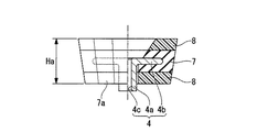
ゴム弾性体7は、図2及び図3に示されるように、下方に向かうに従い漸次狭まる略円錐台状に形成されるとともに、外周部分には軸方向に延びる複数の凹部7aが周方向に等間隔をあけて形成され、これにより、軸方向の回転を規制される平面視非円形形状とされている。ゴム弾性体7の上下両端部には、所定高さの軟質層8がゴム弾性体7と連続するように、ゴム弾性体7と同じ稜線をもって形成されている。
ここで、軟質層8はゴム弾性体7の上下端部に、すなわち、ピストンロッド2の軸方向の端部にそれぞれゴム弾性体7と重なるように形成されていて、それら上下の軟質層8、8と中央のゴム弾性体7とにより、いわゆるサンドイッチ構造をなしている。
軟質層8は、ゴム弾性体7より損失係数が高くかつ低密度の材料、例えば、発泡性のウレタンや軟質ゴム等から作られている。
なお、ゴム弾性体7の形状は必ずしも円錐台状に形成する必要は無く、円錐の無い円柱状に形成してもよい。また、凹部7aについては必ずしも必要なものではなく、凹凸の無い環状でも本発明に適用可能である。
As shown in FIGS. 2 and 3, the rubber
Here, the
The
The shape of the rubber
ストラットマウント1には、内側金具4の外周側に外側金具9が同軸的に配置されており、この外側金具9はボルト10を介して車体に連結されている。
外側金具9は、前記ゴム弾性体7及び軟質層8を圧入状態で支持する収納部9aが形成された外側金具本体11と、収納部9aの開口部分に配置されて、収納部9aに圧入されるゴム弾性体7及び軟質層8の脱落を防止する金属製の脱落防止プレート12とを有している。収納部9aは、前記ゴム弾性体および上下の軟質層8の形状に対応させて、下方に向かうに従い漸次狭まる略円錐台状に形成されていて、そこには、前記ゴム弾性体7及び軟質層8が、アウタープレート等の他の部材を用いることなく、直接収納部9aの内周面に接触するように圧入されている。
In the strut mount 1, an outer metal fitting 9 is coaxially arranged on the outer peripheral side of the
The outer metal fitting 9 is disposed in an outer metal
外側金具本体11は、前記収納部9aを画成する有底筒状部11aと、有庭円筒部11aの上端から外方へ延びる外フランジ部11bとからなっている。一方、脱落防止プレート12は、中央部分に凹部12aを有する略円板形状に形成されていて、凹部12aの中心部には前記ピストンロッド2の先端を挿通させる孔12aaが形成されている。脱落防止プレート12は、収納部9aに前記ゴム弾性体7及び軟質層8が圧入された後、収納部9aの開口側から外側金具本体11に押し付けられた状態で、適宜固着手段、例えばその周辺部の複数個所がスポット溶接されることにより、外側金具本体11に固着されている。
外フランジ部11b及び脱落防止プレート12の外周部にはそれぞれ挿通孔11ba、12bが形成され、これらの挿通孔11ba、12bに前記ボルト10が挿通されることによって、外側金具本体11が車体に連結されている。
The outer metal
Insertion holes 11ba and 12b are formed in the outer peripheral portions of the
ここで、前述したように、前記ゴム弾性体7及び軟質層8が収納部9aに圧入されるため、図1における下側の軟質層8は、収納部9aに対して予圧縮を受けた状態でセットされている。また、ゴム弾性体7及び上下の軟質層8の合計した高さHaは(図3参照)、収納部9aの深さHbよりも(図1参照)、予め予圧縮分を見込んだ分だけ大に設定されており、したがって、ゴム弾性体7及び軟質層8が収納部9aに圧入された後、上側から脱落防止プレート12によって閉止されたときにおいて、図1における上側の軟質層8も、予圧縮を受けた状態で外側金具11内にセットされている。
Here, as described above, since the rubber
また、上下の軟質層8の予圧縮量はストラットマウント1の使用条件やゴム弾性体7の硬度あるいは軟質層8のバネ定数等に応じて設定されるが、例えば、ショックアブソーバのピストンロッド2から外力を受けて軟質層8が変形する場合でも、軟質層8と外側金具9との間に隙間が生じない程度の予圧縮量に設定される。
The pre-compression amount of the upper and lower
ストラットマウント1には、図1に示されるように、外側金具9の外フランジ部11bの下部側にベアリング13が取り付けられている。ベアリング13の下面には、シリンダ部との間で圧縮状態とされた前記コイルスプリング3の上端部が当接されている。前記外側金具9の下側には、アッパーシート14が外側金具9と同軸状に取り付けられており、このアッパーシート14はバンプストッパの上端と係合している。
As shown in FIG. 1, a
上記のように構成されたストラットマウント1を車体へ取り付ける際には、脱落防止プレート12を介して外側金具本体11の外フランジ部11bを車体の取付部の下面側へ突き当て、この状態で、ボルト10を下側から外フランジ部11bの挿通孔11ba、脱落防止プレート12の挿通孔12b及び車体の挿通穴へ挿通し、このボルト10の先端部にナットを所定の締結トルクが発生するまでねじ込む。これにより、ストラットマウント1を車体の取付部へ締結固定し、このストラットマウント1を介してショックアブソーバを車体へマウントさせることができる。
When attaching the strut mount 1 configured as described above to the vehicle body, the
次に、上記のように構成されたストラットマウント1の作用を説明する。
本実施形態のストラットマウント1では、ゴム弾性体7の上下端部にそれぞれ軟質層8を設けており、この軟質層8をゴム弾性体7より損失係数が高くかつ低密度としている。この結果、軟質層8は、ゴム弾性体7より損失係数が高くかつ動的バネ定数が低くなっている。したがって、高速走行時等に生じがちな、ピストンロッド2からストラットマウント1へ入力する微小な高周波振動を、軟質層8が適宜変形することによって効果的に吸収することができる。
Next, the operation of the strut mount 1 configured as described above will be described.
In the strut mount 1 of this embodiment, the
一方、車両が縁石等の段差を乗り越える等に起因してショックアブソーバのピストンロッド2からストラットマウント1への入力荷重が突発的に大きくなる場合には、主に軟質層8よりも高剛性のゴム弾性体7が適宜変形してその大きな入力荷重を吸収する。
On the other hand, when the input load from the piston rod 2 of the shock absorber to the strut mount 1 suddenly increases due to the vehicle overcoming a step such as a curb stone, the rubber mainly having higher rigidity than the
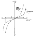
この場合のピストンロッド2の軸方向に沿った変位量と入力荷重との関係を図4に示す。図4において、横軸にはピストンロッド2の軸方向に沿った変位量、縦軸にはピストンロッド2からストラットマウント1への入力荷重をとっている。
なお、この図において、2点鎖線は、内側金具と外側金具との間に軟質層を有さずゴム弾性体のみを介装させた従来のストラットマウントのピストンロッドの軸方向に沿った変位量と入力荷重との関係を示している。
FIG. 4 shows the relationship between the displacement amount along the axial direction of the piston rod 2 and the input load in this case. In FIG. 4, the horizontal axis represents the amount of displacement along the axial direction of the piston rod 2, and the vertical axis represents the input load from the piston rod 2 to the strut mount 1.
In this figure, the alternate long and two short dashes line indicates the amount of displacement along the axial direction of the piston rod of the conventional strut mount that does not have a soft layer between the inner metal fitting and the outer metal fitting and is interposed only with a rubber elastic body. And the input load.
図4から明らかなように、本実施形態におけるストラットマウント1は、ゴム弾性体7及び軟質層8の双方の特性を有効に利用できるので、特性線形域Zを大きくとることができる。加えて、このように高周波振動の吸収を考慮することなく、大きな入力荷重に対処するためゴム弾性体7の硬度を任意に上げて剛性を高めることができるので、その分、ゴム弾性体7ひいてはストラットマウント1の耐久性の向上を図ることができる。
As can be seen from FIG. 4, the strut mount 1 according to the present embodiment can effectively utilize the characteristics of both the rubber
また、前記構成のストラットマウント1では、軟質層8を、ゴム弾性体7における上下端部、つまりピストンロッド2の軸方向の端部に形成しており、ピストンロッド2や車体からピストンロッド2の軸方向に沿って加わる力に対して、軟質層8には剪断力ではなく圧縮力や引張力が作用することとなる。この種の軟質層8では、特に圧縮力が作用する場合、剪断力が作用するのに比べて十分な耐力を有することなり、軟質層8における十分な耐力を有効に利用でき、結果的にストラットマウント1の耐久性の向上を図ることができる。
また、軟質層8を、図1に示されるように、ゴム弾性体7における上下端部にのみに形成する場合には、当該ストラットマウント1により、ピストンロッド2の軸方向の動きのみを所定量許容しつつ、ピストンロッドの軸線方向に直交する例えば前後左右方向の動きを比較的剛に支持することができ、理想的なストラットマウント1を得ることができる。
In the strut mount 1 having the above-described configuration, the
Further, when the
また、前記構成のストラットマウント1において、軟質層8を、例えば、発泡ウレタンにより形成する場合には、入手し易くかつ安価な材料によって軟質層8を作ることができ、よって、容易かつローコストで、ストラットマウント1を制作することができる。
Moreover, in the strut mount 1 having the above-described configuration, when the
また、構成のストラットマウント1では、ゴム弾性体7を、アウタープレート等の他の部材を用いることなく、その径方向外周面を収納部9aの内周面に直接接触させて収納部9aに圧入しており、他の部材を用いて外側金具9にセットする場合に比べて、他の部材の厚みの分だけ、コンパクト化を図ることができる。
In the strut mount 1 having the configuration, the rubber
また、構成のストラットマウント1では、前記軟質層8に予圧縮をかけて収納部9aに圧入しているので、軟質層8に力が加わって変形する場合でも、軟質層8と収納部9aの間に隙間が生じにくく、このため、両者に隙間が存することに起因する打音等の異音の発生をより防止することができる。
Further, in the strut mount 1 having the configuration, the
なお、本発明は、前記実施形態に限定されることなく、発明の趣旨を逸脱しない範囲において適宜設計変更可能である。
例えば、前記実施形態では、内側金具4の外フランジ部4bを囲むようにゴム弾性体7を設け、このゴム弾性体7の上下端部にそれぞれ軟質層8を設けているが、これに限られることなく、図5に示すように、ゴム弾性体7の外周部にも軟質層8aを設け、この軟質層8aを上下の軟質層8とつなげるように構成しても良い。
また、前記実施形態では、ゴム弾性体7の上下端部にそれぞれ軟質層8を設けているが、これに限られることなく、上下端部のいずれか一方側にのみ、軟質層8を設けても良い。
更に、車体取り付け部が脱落防止機能を持つ場合、脱落防止プレートが無い構成でも本発明の目的を達成し、効果を得ることができるのは言うまでもない。
The present invention is not limited to the above-described embodiment, and can be appropriately changed in design without departing from the spirit of the invention.
For example, in the said embodiment, the rubber
Moreover, in the said embodiment, although the
Furthermore, when the vehicle body attachment portion has a drop-off prevention function, it goes without saying that the object of the present invention can be achieved and the effect can be obtained even with a configuration without the drop-off prevention plate.
1 ストラットマウント
2 ピストンロッド
3 コイルスプリング
4 内側金具
7 ゴム弾性体
8 軟質層
9 外側金具
11 外側金具本体
12 脱落防止プレート
DESCRIPTION OF SYMBOLS 1 Strut mount 2
Claims (9)
ショックアブソーバのピストンロッドに取り付けられた内側金具と、
前記内側金具の外周に前記内側金具と一体的に形成された状態で、前記外側金具の収納部に圧入されることにより、前記外側金具と前記内側金具との間に介装されるゴム弾性体と、を備えるストラットマウントにおいて、
前記外側金具と前記ゴム弾性体との間に、前記ゴム弾性体より損失係数が高くかつ低密度の軟質層が介装されたことを特徴とするストラットマウント。 An outer bracket attached to the car body,
An inner bracket attached to the piston rod of the shock absorber,
A rubber elastic body interposed between the outer metal fitting and the inner metal fitting by being press-fitted into a housing portion of the outer metal fitting while being integrally formed with the inner metal fitting on the outer circumference of the inner metal fitting. In a strut mount comprising:
A strut mount, wherein a soft layer having a loss factor higher than that of the rubber elastic body and having a low density is interposed between the outer metal fitting and the rubber elastic body.
Priority Applications (1)
| Application Number | Priority Date | Filing Date | Title |
|---|---|---|---|
| JP2005293400A JP4841923B2 (en) | 2005-10-06 | 2005-10-06 | Strut mount |
Applications Claiming Priority (1)
| Application Number | Priority Date | Filing Date | Title |
|---|---|---|---|
| JP2005293400A JP4841923B2 (en) | 2005-10-06 | 2005-10-06 | Strut mount |
Publications (2)
| Publication Number | Publication Date |
|---|---|
| JP2007100889A true JP2007100889A (en) | 2007-04-19 |
| JP4841923B2 JP4841923B2 (en) | 2011-12-21 |
Family
ID=38028040
Family Applications (1)
| Application Number | Title | Priority Date | Filing Date |
|---|---|---|---|
| JP2005293400A Expired - Fee Related JP4841923B2 (en) | 2005-10-06 | 2005-10-06 | Strut mount |
Country Status (1)
| Country | Link |
|---|---|
| JP (1) | JP4841923B2 (en) |
Cited By (18)
| Publication number | Priority date | Publication date | Assignee | Title |
|---|---|---|---|---|
| JP2009264553A (en) * | 2008-04-28 | 2009-11-12 | Toyo Tire & Rubber Co Ltd | Suspension support |
| JP2009264457A (en) * | 2008-04-23 | 2009-11-12 | Kurashiki Kako Co Ltd | Upper mount |
| JP2010014132A (en) * | 2008-06-30 | 2010-01-21 | Tokai Rubber Ind Ltd | Upper support |
| JP2010281412A (en) * | 2009-06-05 | 2010-12-16 | Bridgestone Corp | Strut mount |
| JP2011088570A (en) * | 2009-10-23 | 2011-05-06 | Toyo Tire & Rubber Co Ltd | Suspension support |
| JP2011169416A (en) * | 2010-02-19 | 2011-09-01 | Toyo Tire & Rubber Co Ltd | Suspension support |
| JP2011174563A (en) * | 2010-02-25 | 2011-09-08 | Toyo Tire & Rubber Co Ltd | Suspension support |
| JP2012180873A (en) * | 2011-02-28 | 2012-09-20 | Toyo Tire & Rubber Co Ltd | Strut mount and method of manufacturing the same |
| JP2013122252A (en) * | 2011-12-09 | 2013-06-20 | Bridgestone Corp | Strut mount |
| WO2014122842A1 (en) | 2013-02-06 | 2014-08-14 | トヨタ自動車株式会社 | Suspension mount |
| JP2015140900A (en) * | 2014-01-30 | 2015-08-03 | Nok株式会社 | Vibration insulation mount |
| JP2015168393A (en) * | 2014-03-10 | 2015-09-28 | トヨタ自動車株式会社 | Strut type suspension device |
| KR20190065573A (en) * | 2017-12-04 | 2019-06-12 | 현대자동차주식회사 | Insulator of shock absorber for automobile |
| JP2020199917A (en) * | 2019-06-11 | 2020-12-17 | 株式会社ブリヂストン | Cab mount |
| JP2022057791A (en) * | 2020-09-30 | 2022-04-11 | 株式会社ブリヂストン | Strut mount |
| DE102008029018B4 (en) | 2008-06-18 | 2022-05-12 | Schaeffler Technologies AG & Co. KG | strut bearing |
| CN115388126A (en) * | 2022-09-30 | 2022-11-25 | 阿维塔科技(重庆)有限公司 | Air spring shock absorber assembly and vehicle |
| JP2023517226A (en) * | 2020-03-18 | 2023-04-24 | 浙江吉利控股集団有限公司 | Strut assembly and vehicle using same |
Families Citing this family (1)
| Publication number | Priority date | Publication date | Assignee | Title |
|---|---|---|---|---|
| KR20170115860A (en) * | 2016-04-08 | 2017-10-18 | 현대자동차주식회사 | Vehicle suspension |
Citations (2)
| Publication number | Priority date | Publication date | Assignee | Title |
|---|---|---|---|---|
| JPS6012736A (en) * | 1984-05-21 | 1985-01-23 | Gosen Sangyo Kk | Cartridge mainly used for cleaning or drying device |
| JPS6024954A (en) * | 1983-07-20 | 1985-02-07 | Canon Inc | Detection of residual ink amount in ink jet printer |
-
2005
- 2005-10-06 JP JP2005293400A patent/JP4841923B2/en not_active Expired - Fee Related
Patent Citations (2)
| Publication number | Priority date | Publication date | Assignee | Title |
|---|---|---|---|---|
| JPS6024954A (en) * | 1983-07-20 | 1985-02-07 | Canon Inc | Detection of residual ink amount in ink jet printer |
| JPS6012736A (en) * | 1984-05-21 | 1985-01-23 | Gosen Sangyo Kk | Cartridge mainly used for cleaning or drying device |
Cited By (30)
| Publication number | Priority date | Publication date | Assignee | Title |
|---|---|---|---|---|
| JP2009264457A (en) * | 2008-04-23 | 2009-11-12 | Kurashiki Kako Co Ltd | Upper mount |
| JP2009264553A (en) * | 2008-04-28 | 2009-11-12 | Toyo Tire & Rubber Co Ltd | Suspension support |
| DE102008029018B4 (en) | 2008-06-18 | 2022-05-12 | Schaeffler Technologies AG & Co. KG | strut bearing |
| JP2010014132A (en) * | 2008-06-30 | 2010-01-21 | Tokai Rubber Ind Ltd | Upper support |
| JP2010281412A (en) * | 2009-06-05 | 2010-12-16 | Bridgestone Corp | Strut mount |
| JP2011088570A (en) * | 2009-10-23 | 2011-05-06 | Toyo Tire & Rubber Co Ltd | Suspension support |
| JP2011169416A (en) * | 2010-02-19 | 2011-09-01 | Toyo Tire & Rubber Co Ltd | Suspension support |
| JP2011174563A (en) * | 2010-02-25 | 2011-09-08 | Toyo Tire & Rubber Co Ltd | Suspension support |
| JP2012180873A (en) * | 2011-02-28 | 2012-09-20 | Toyo Tire & Rubber Co Ltd | Strut mount and method of manufacturing the same |
| JP2013122252A (en) * | 2011-12-09 | 2013-06-20 | Bridgestone Corp | Strut mount |
| EP2955409A4 (en) * | 2013-02-06 | 2016-04-27 | Toyota Motor Co Ltd | Suspension mount |
| WO2014122842A1 (en) | 2013-02-06 | 2014-08-14 | トヨタ自動車株式会社 | Suspension mount |
| CN104981625A (en) * | 2013-02-06 | 2015-10-14 | 丰田自动车株式会社 | Suspension mount |
| JP2014152821A (en) * | 2013-02-06 | 2014-08-25 | Toyota Motor Corp | Suspension mount |
| US9452651B2 (en) | 2013-02-06 | 2016-09-27 | Toyota Jidosha Kabushiki Kaisha | Suspension mount |
| JP2015140900A (en) * | 2014-01-30 | 2015-08-03 | Nok株式会社 | Vibration insulation mount |
| JP2015168393A (en) * | 2014-03-10 | 2015-09-28 | トヨタ自動車株式会社 | Strut type suspension device |
| CN106103146A (en) * | 2014-03-10 | 2016-11-09 | 丰田自动车株式会社 | Strut type suspension system |
| TWI576258B (en) * | 2014-03-10 | 2017-04-01 | 豐田自動車股份有限公司 | Strut-type suspension device |
| US9662953B2 (en) | 2014-03-10 | 2017-05-30 | Toyota Jidosha Kabushiki Kaisha | Strut-type suspension device |
| KR20190065573A (en) * | 2017-12-04 | 2019-06-12 | 현대자동차주식회사 | Insulator of shock absorber for automobile |
| KR102416791B1 (en) * | 2017-12-04 | 2022-07-05 | 현대자동차주식회사 | Insulator of shock absorber for automobile |
| JP2020199917A (en) * | 2019-06-11 | 2020-12-17 | 株式会社ブリヂストン | Cab mount |
| JP7219169B2 (en) | 2019-06-11 | 2023-02-07 | 株式会社プロスパイラ | cab mount |
| JP2023517226A (en) * | 2020-03-18 | 2023-04-24 | 浙江吉利控股集団有限公司 | Strut assembly and vehicle using same |
| JP7471439B2 (en) | 2020-03-18 | 2024-04-19 | 浙江吉利控股集団有限公司 | Strut assembly and vehicle using same |
| US12023975B2 (en) | 2020-03-18 | 2024-07-02 | Zhejiang Geely Holding Group Co., Ltd. | Strut assembly and vehicle applying same |
| JP2022057791A (en) * | 2020-09-30 | 2022-04-11 | 株式会社ブリヂストン | Strut mount |
| JP7487062B2 (en) | 2020-09-30 | 2024-05-20 | 株式会社プロスパイラ | Strut mount |
| CN115388126A (en) * | 2022-09-30 | 2022-11-25 | 阿维塔科技(重庆)有限公司 | Air spring shock absorber assembly and vehicle |
Also Published As
| Publication number | Publication date |
|---|---|
| JP4841923B2 (en) | 2011-12-21 |
Similar Documents
| Publication | Publication Date | Title |
|---|---|---|
| JP4841923B2 (en) | Strut mount | |
| JP6190651B2 (en) | Vibration isolator | |
| JP4421500B2 (en) | Vibration isolator | |
| JP2022145668A (en) | Lateral vibration isolator mechanism for vehicle seat back | |
| JP4759527B2 (en) | Vibration control device | |
| JP5786876B2 (en) | Suspension mount | |
| JP2010090995A (en) | Strut mount | |
| JP2007127173A (en) | Bound stopper | |
| KR102563031B1 (en) | strut mount of suspension for vehicle | |
| JPH1151106A (en) | Dust cover mounting structure | |
| JP2010090996A (en) | Strut mount and strut mount manufacturing method | |
| JP4680150B2 (en) | Vibration isolator | |
| JPH11325145A (en) | Vibration isolating rubber bush | |
| US20020084614A1 (en) | Structure for mounting shock abosorber and spring to suspension apparatus | |
| JP5761513B2 (en) | Strut mount structure | |
| RU2270762C1 (en) | Device for fastening spring strut of automobile suspension | |
| JP4017213B2 (en) | Anti-vibration mechanism | |
| JPS639441Y2 (en) | ||
| JP2935128B2 (en) | Mounting suspension equipment | |
| JP2006084007A (en) | Upper support for suspension | |
| JP2020142676A (en) | Vibration isolating bush for axle beam device | |
| JP2003106366A (en) | Suspension system | |
| JP2009085300A (en) | Upper support | |
| JP2007127172A (en) | Strut mount | |
| JP2001221273A (en) | Shock absorber mounting structure |
Legal Events
| Date | Code | Title | Description |
|---|---|---|---|
| A621 | Written request for application examination |
Free format text: JAPANESE INTERMEDIATE CODE: A621 Effective date: 20080909 |
|
| A977 | Report on retrieval |
Free format text: JAPANESE INTERMEDIATE CODE: A971007 Effective date: 20100715 |
|
| A131 | Notification of reasons for refusal |
Free format text: JAPANESE INTERMEDIATE CODE: A131 Effective date: 20101220 |
|
| A521 | Request for written amendment filed |
Free format text: JAPANESE INTERMEDIATE CODE: A523 Effective date: 20110217 |
|
| TRDD | Decision of grant or rejection written | ||
| A01 | Written decision to grant a patent or to grant a registration (utility model) |
Free format text: JAPANESE INTERMEDIATE CODE: A01 Effective date: 20110927 |
|
| A01 | Written decision to grant a patent or to grant a registration (utility model) |
Free format text: JAPANESE INTERMEDIATE CODE: A01 |
|
| A61 | First payment of annual fees (during grant procedure) |
Free format text: JAPANESE INTERMEDIATE CODE: A61 Effective date: 20111005 |
|
| R150 | Certificate of patent or registration of utility model |
Ref document number: 4841923 Country of ref document: JP Free format text: JAPANESE INTERMEDIATE CODE: R150 Free format text: JAPANESE INTERMEDIATE CODE: R150 |
|
| FPAY | Renewal fee payment (event date is renewal date of database) |
Free format text: PAYMENT UNTIL: 20141014 Year of fee payment: 3 |
|
| R250 | Receipt of annual fees |
Free format text: JAPANESE INTERMEDIATE CODE: R250 |
|
| R250 | Receipt of annual fees |
Free format text: JAPANESE INTERMEDIATE CODE: R250 |
|
| R250 | Receipt of annual fees |
Free format text: JAPANESE INTERMEDIATE CODE: R250 |
|
| R250 | Receipt of annual fees |
Free format text: JAPANESE INTERMEDIATE CODE: R250 |
|
| R250 | Receipt of annual fees |
Free format text: JAPANESE INTERMEDIATE CODE: R250 |
|
| R250 | Receipt of annual fees |
Free format text: JAPANESE INTERMEDIATE CODE: R250 |
|
| R250 | Receipt of annual fees |
Free format text: JAPANESE INTERMEDIATE CODE: R250 |
|
| R250 | Receipt of annual fees |
Free format text: JAPANESE INTERMEDIATE CODE: R250 |
|
| S111 | Request for change of ownership or part of ownership |
Free format text: JAPANESE INTERMEDIATE CODE: R313111 |
|
| S531 | Written request for registration of change of domicile |
Free format text: JAPANESE INTERMEDIATE CODE: R313531 |
|
| R350 | Written notification of registration of transfer |
Free format text: JAPANESE INTERMEDIATE CODE: R350 |
|
| R250 | Receipt of annual fees |
Free format text: JAPANESE INTERMEDIATE CODE: R250 |
|
| LAPS | Cancellation because of no payment of annual fees |