JP2009085300A - Upper support - Google Patents
Upper support Download PDFInfo
- Publication number
- JP2009085300A JP2009085300A JP2007254388A JP2007254388A JP2009085300A JP 2009085300 A JP2009085300 A JP 2009085300A JP 2007254388 A JP2007254388 A JP 2007254388A JP 2007254388 A JP2007254388 A JP 2007254388A JP 2009085300 A JP2009085300 A JP 2009085300A
- Authority
- JP
- Japan
- Prior art keywords
- spring
- rubber elastic
- elastic body
- upper support
- metal
- Prior art date
- Legal status (The legal status is an assumption and is not a legal conclusion. Google has not performed a legal analysis and makes no representation as to the accuracy of the status listed.)
- Pending
Links
Images


Abstract
Description
この発明は車両のサスペンション装置に用いられるアッパーサポート、特にコイルスプリングにて車体の荷重を直接受ける形式のサスペンション装置に用いられるアッパーサポートに関する。 The present invention relates to an upper support used in a vehicle suspension device, and more particularly to an upper support used in a suspension device of a type that directly receives a load of a vehicle body by a coil spring.
自動車のサスペンション装置には従来から様々な形式のものがあり、その一つとして、ショックアブソーバと金属製のコイルスプリングとを有し、ショックアブソーバのピストンロッドをゴム弾性体を要素として備えたアッパーサポートにて車体に弾性連結する一方、コイルスプリングにて車体の荷重をアッパーサポートを介さずに直接受ける形式のものがある。 Conventionally, there are various types of suspension systems for automobiles, and one of them is an upper support that has a shock absorber and a metal coil spring, and the piston rod of the shock absorber has a rubber elastic body as an element. There is a type in which the load of the vehicle body is directly received by the coil spring without going through the upper support while being elastically connected to the vehicle body.
例えば下記特許文献1に、この種のアッパーサポートが開示されている。
図7はその具体例を示している。
図において200はピストンロッドで、202はゴム弾性体204を主要素として含んだアッパーサポートである。
ゴム弾性体204は上下に2分割されており、そして上分割体206と、下分割体208とで剛性の取付ブラケット210を上下に挟み込む状態にピストンロッド200に取り付けられている。
For example, Patent Document 1 listed below discloses this type of upper support.
FIG. 7 shows a specific example thereof.
In the figure,
The rubber
ピストンロッド200は上端部に雄ねじ部212を有していて、そこにナット214が螺合されている。
そしてそのナット214の螺合により、一対のワッシャ216,218が上分割体206,下分割体208及び筒状のインナ部材220を上下方向に挟み込んでいる。
The
The pair of
ところで上記形式のサスペンション装置において、ショックアブソーバは約20Hz程度までの低周波数領域ではピストン運動が振動入力に対して十分に追従し得て、かかる低周波数領域且つ大振幅入力時に良好に減衰力を発揮することができる。
ところが入力振動の周波数が20Hzを超えて高周波数となったときにピストン運動が振動入力に追従し得なくなり、ショックアブソーバが剛体化する。詳しくはショックアブソーバがより剛体に近い挙動をするようになる。
By the way, in the suspension device of the above type, the shock absorber can sufficiently follow the vibration input in the low frequency region up to about 20 Hz, and exhibits a good damping force in the low frequency region and large amplitude input. can do.
However, when the frequency of the input vibration exceeds 20 Hz and becomes a high frequency, the piston motion cannot follow the vibration input, and the shock absorber becomes rigid. Specifically, the shock absorber behaves more like a rigid body.
この場合アッパーサポートのばね定数(上下方向の動的ばね定数)が高く硬いと(高剛性であると)、剛体化したショックアブソーバを介して入力した振動が車体へと伝わり易く、乗心地性能を悪化させてしまう。
従ってこのときにはアッパーサポートのばね定数は低く、軟らかいものであることが望ましい。
このようにすれば、ショックアブソーバに伝わった入力振動をアッパーサポートにおけるゴム弾性体の弾性変形により良好に吸収でき、入力振動が車体へと伝達されるのを良好に抑制することができる。
In this case, if the upper support spring constant (dynamic spring constant in the vertical direction) is high and hard (high rigidity), the vibration input through the rigid shock absorber can be easily transmitted to the vehicle body, resulting in improved ride performance. It gets worse.
Therefore, at this time, it is desirable that the spring constant of the upper support is low and soft.
In this way, the input vibration transmitted to the shock absorber can be satisfactorily absorbed by the elastic deformation of the rubber elastic body in the upper support, and the input vibration can be satisfactorily suppressed from being transmitted to the vehicle body.
しかしながら一方で、アッパーサポートのばね定数を低く軟らかいものにしておくと、低周波数領域での大振幅入力の際にアッパーサポートが弾性変形し易く、ショックアブソーバのピストン運動を減殺してしまって、ショックアブソーバの減衰力を十分に引き出すことができなくなってしまう。
従ってアッパーサポートとしては、低周波数領域ではばね定数(静的ばね定数)が高く、硬いものであることが望ましい。
However, if the spring constant of the upper support is made low and soft, the upper support is likely to be elastically deformed when a large amplitude is input in the low frequency range, and the piston motion of the shock absorber is reduced. It will not be possible to draw out the damping force of the absorber sufficiently.
Therefore, it is desirable that the upper support has a high spring constant (static spring constant) in the low frequency region and is hard.
アッパーサポートのばね定数を上記のように設定することができれば、低周波数領域且つ大振幅入力時には、ショックアブソーバの振動減衰力を十分に引き出すことができ、またショックアブソーバが剛体化する高周波数領域且つ微小振幅入力時には、アッパーサポートにより振動を良好に吸収でき、車体に振動が伝達されるのを効果的に抑制することができる。
因みにショックアブソーバは例えば1Hzで±20mmのストロークでピストン運動することができるが、20Hzでは±5mm程度となり、100Hzになると±0.05mm程度となる。
If the spring constant of the upper support can be set as described above, the vibration damping force of the shock absorber can be sufficiently extracted at the time of low frequency region and large amplitude input, and the high frequency region where the shock absorber becomes rigid and When a minute amplitude is input, vibration can be satisfactorily absorbed by the upper support, and transmission of vibration to the vehicle body can be effectively suppressed.
Incidentally, the shock absorber can move the piston with a stroke of ± 20 mm at 1 Hz, for example, but is about ± 5 mm at 20 Hz, and about ± 0.05 mm at 100 Hz.
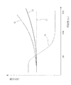
従ってアッパーサポートの理想的なばね特性は、図2のAに示すようなものとなる。
つまりアッパーサポートにとって理想的なばね特性は、低周波数領域の静的ばね特性と、高周波数領域での動的ばね特性とが全く逆の関係のものとなる。
Therefore, the ideal spring characteristic of the upper support is as shown in FIG.
That is, the ideal spring characteristic for the upper support has a completely opposite relationship between the static spring characteristic in the low frequency region and the dynamic spring property in the high frequency region.
しかしながらアッパーサポートにおけるゴム弾性体は粘弾性を有するもので、静的ばね定数に対して高周波数領域でばね定数が低くなることはなく、周波数が高くなればなる程、その有する粘性に基づいてばね定数(動的ばね定数)が図2のBで示すように高くなる。
従ってばねとしてゴム弾性体のみを用いた従来のアッパーサポートでは、上記の理想的なばね特性を実際に実現することはできず、そこで従来にあっては、低周波数領域での高いばね定数(硬いばね特性)による大きな振動減衰,操縦安定性と、高周波数領域での低いばね定数(軟らかいばね特性)による乗心地性能とをバランスさせるように、ゴム弾性体の静的ばね特性,動的ばね特性を設定しているのが実状である。
However, the rubber elastic body in the upper support has viscoelasticity, and the spring constant does not decrease in the high frequency region with respect to the static spring constant, and the higher the frequency, the more the spring is based on its viscosity. The constant (dynamic spring constant) increases as shown by B in FIG.
Therefore, with the conventional upper support using only the rubber elastic body as the spring, the above ideal spring characteristics cannot be actually realized. Therefore, in the past, a high spring constant (hard The elastic and static spring characteristics of the rubber elastic body balance the large vibration damping and steering stability due to the spring characteristics) and the riding comfort performance due to the low spring constant (soft spring characteristics) in the high frequency range. Is the actual situation.
またアッパーサポートにあっては上下方向の動ばね特性に対して左右方向の動ばね特性を硬く設定することが望ましいが、スペースの関係もあって両立できていないのが実状である。 Further, in the upper support, it is desirable to set the left and right dynamic spring characteristics to be harder than the vertical dynamic spring characteristics, but the actual situation is that they are not compatible because of space.
本発明は以上のような事情を背景とし、低周波数且つ大振幅での振動入力時には、ばね定数を高く設定することができる一方、高周波数且つ小振幅での振動入力時にはばね定数を低く設定することができ、低周波数での大きな振動減衰性能と高周波数での良好な微小振動の吸収性能との、相反する性能を両立し得るアッパーサポートを提供することを目的としてなされたものである。
また本発明の他の目的は、アッパーサポートの左右剛性を高くし得て操縦安定性をより一層高めることを目的とする。
In the present invention, the spring constant can be set high at the time of vibration input at a low frequency and a large amplitude while the spring constant is set low at the time of vibration input at a high frequency and a small amplitude. Therefore, the present invention has been made for the purpose of providing an upper support capable of satisfying both contradictory performances of large vibration damping performance at a low frequency and good micro vibration absorption performance at a high frequency.
Another object of the present invention is to increase the left-right rigidity of the upper support and further improve the steering stability.
而して請求項1のものは、コイルスプリングとショックアブソーバとを有し、該ショックアブソーバのピストンロッドがゴム弾性体を要素として含むアッパーサポートにて車体に弾性連結される一方、該コイルスプリングにて車体の荷重を該アッパーサポートを介さずに直接受ける形式の車両のサスペンション装置に用いられる前記アッパーサポートであって、前記アッパーサポートを、主ばねとしての金属ばねと補助ばねとしての前記ゴム弾性体とを複合化した複合ばねにて構成してあることを特徴とする。 Thus, the first aspect of the present invention has a coil spring and a shock absorber, and a piston rod of the shock absorber is elastically connected to the vehicle body by an upper support including a rubber elastic body as an element. The upper support is used in a vehicle suspension apparatus that directly receives the load of the vehicle body without going through the upper support, and the upper support is made of a metal spring as a main spring and the rubber elastic body as an auxiliary spring. It is characterized by comprising a composite spring in which
請求項2のものは、請求項1において、前記金属ばねと前記ゴム弾性体とが前記ピストンロッドと前記車体との間に直列又は/及び並列に配置してあることを特徴とする。 According to a second aspect of the present invention, in the first aspect, the metal spring and the rubber elastic body are arranged in series or / and in parallel between the piston rod and the vehicle body.
請求項3のものは、請求項1,2の何れかにおいて、前記金属ばねとして金属板ばねを用いていることを特徴とする。 According to a third aspect of the present invention, in any one of the first and second aspects, a metal leaf spring is used as the metal spring.
請求項4のものは、請求項1,2の何れかにおいて、前記金属ばねとしてコイルばねを用いていることを特徴とする。 According to a fourth aspect of the present invention, in any one of the first and second aspects, a coil spring is used as the metal spring.
請求項5のものは、請求項1において、前記ゴム弾性体を上下の分割構造となして前記ピストンロッドに取り付けてあり、該ゴム弾性体の上分割体と下分割体との間に、一端側が前記車体に固定された前記金属ばねとしての金属板ばねの他端側を上下に挟み込む状態に、それらゴム弾性体と金属板ばねとを直列配置状態に複合化してあることを特徴とする。 According to a fifth aspect of the present invention, in the first aspect, the rubber elastic body has an upper and lower divided structure and is attached to the piston rod, and the rubber elastic body has one end between the upper divided body and the lower divided body. The rubber elastic body and the metal plate spring are combined in a series arrangement state so that the other end side of the metal plate spring as the metal spring fixed to the vehicle body is sandwiched up and down.
請求項6のものは、請求項1において、前記ゴム弾性体が一体加硫成形されていて該ゴム弾性体が前記ピストンロッドに取り付けてあり、一端側が前記車体に固定された前記金属ばねとしての金属板ばねの他端側を、該ゴム弾性体の上部と下部とで上下に挟み込む状態に該ゴム弾性体が該金属板ばねと一体加硫接着されており、それらゴム弾性体と金属板ばねとが直列配置状態に複合化してあることを特徴とする。 A sixth aspect of the present invention is the metal spring according to the first aspect, wherein the rubber elastic body is integrally vulcanized and molded, the rubber elastic body is attached to the piston rod, and one end side is fixed to the vehicle body. The rubber elastic body is integrally vulcanized and bonded to the metal plate spring so that the other end side of the metal plate spring is sandwiched between the upper and lower portions of the rubber elastic body. The rubber elastic body and the metal plate spring Are combined in a series arrangement state.
請求項7のものは、請求項1において、前記ゴム弾性体を上下の分割構造となし、一端側が前記車体に固定された剛性の取付ブラケットの他端側を該ゴム弾性体の上分割体と下分割体とで上下に挟む状態に、該ゴム弾性体が前記ピストンロッドに取り付けてあるとともに、前記金属ばねとして上,下の一対のコイルばねを用い、上コイルばね,下コイルばねのそれぞれが、対応する前記ゴム弾性体の上分割体,下分割体のそれぞれとともに、前記取付ブラケットの他端側を上下に挟み込む状態に、それらゴム弾性体及びコイルばねが並列配置状態に複合化してあることを特徴とする。 According to a seventh aspect of the present invention, in the first aspect, the rubber elastic body has an upper and lower divided structure, and the other end side of the rigid mounting bracket whose one end side is fixed to the vehicle body is the upper divided body of the rubber elastic body. The rubber elastic body is attached to the piston rod so as to be sandwiched vertically between the lower divided body, and a pair of upper and lower coil springs are used as the metal spring, and each of the upper coil spring and the lower coil spring is The rubber elastic body and the coil spring are combined in a state of being arranged in parallel so that the other end side of the mounting bracket is sandwiched vertically together with the corresponding upper and lower divided bodies of the rubber elastic body. It is characterized by.
以上のように本発明は、アッパーサポートを主ばねとしての金属ばねと、補助ばねとしてのゴム弾性体とを複合化した複合ばねにて構成したものである。
上記のようにゴム弾性体は粘弾性を有しており、その粘性に基づいて周波数が高くなる程、ばね定数(動的ばね定数)が高くなる。即ちゴム弾性体のばね定数は周波数依存性を有している。
これに対し金属ばねは、周波数が高くなってもばね定数が特に高くなるといったことはなく、実質的に周波数依存性を有していない。
As described above, according to the present invention, the upper support is constituted by a composite spring in which the metal spring as the main spring and the rubber elastic body as the auxiliary spring are combined.
As described above, the rubber elastic body has viscoelasticity, and the higher the frequency based on the viscosity, the higher the spring constant (dynamic spring constant). That is, the spring constant of the rubber elastic body has frequency dependency.
On the other hand, the metal spring does not have a particularly high spring constant even when the frequency is high, and has substantially no frequency dependence.
従ってアッパーサポートをこのような主ばねとしての金属ばねと、補助ばねとしてのゴム弾性体とを複合化した複合ばねにて構成することで、ゴム弾性体単独でアッパーサポートのばねを構成した場合に較べて、周波数の上昇に伴うばね定数の上昇の程度を小さく抑えることができる。 Therefore, when the upper support is composed of a metal spring as a main spring and a composite spring in which a rubber elastic body as an auxiliary spring is combined, the upper support spring is composed of the rubber elastic body alone. In comparison, the degree of increase in the spring constant accompanying the increase in frequency can be reduced.
従って本発明によれば、大振幅且つ低周波数での振動入力時におけるアッパーサポートのばね特性を硬く設定し得て、ショックアブソーバの振動減衰力を効果的に引き出すことができ、大振幅且つ低周波数での振動入力時に車体への振動伝達を良好に抑制することができる。 Therefore, according to the present invention, the spring characteristic of the upper support at the time of vibration input at a large amplitude and a low frequency can be set hard, and the vibration damping force of the shock absorber can be effectively extracted. The vibration transmission to the vehicle body can be satisfactorily suppressed during vibration input at.
また一方、微小振幅且つ高周波数での振動入力時には、周波数が高くなることに伴う動ばね定数の上昇を抑制し得て、かかる動ばね定数を従来よりも小さく設定することができ、微小振幅の高周波の振動をアッパーサポートで良好に吸収し得て、かかる高周波の振動が車体に伝わるのを効果的に抑制することができる。 On the other hand, at the time of vibration input with a small amplitude and a high frequency, an increase in the dynamic spring constant associated with an increase in frequency can be suppressed, and the dynamic spring constant can be set smaller than the conventional one. High frequency vibrations can be satisfactorily absorbed by the upper support, and transmission of such high frequency vibrations to the vehicle body can be effectively suppressed.
尚、アッパーサポート全体のばね定数に対する金属ばねのばね定数の寄与率を大とし、ゴム弾性体のばね定数の寄与率を小とすることで、振動周波数の高周波数化に伴う動的ばね定数の上昇の程度をより低く抑制することができ、望ましい。 In addition, by increasing the contribution rate of the spring constant of the metal spring to the spring constant of the entire upper support and reducing the contribution rate of the spring constant of the rubber elastic body, the dynamic spring constant associated with the increase in the vibration frequency is reduced. The degree of increase can be suppressed lower, which is desirable.
この意味において、金属ばね単体でアッパーサポートのばねを構成するといったことも考えられるが、そのようにした場合、ピストンロッドのこじりその他上下動以外の不規則な運動に起因したピストンロッドと車体との間の相対変位を良好に吸収できない場合が生ずる。
しかるにアッパーサポートのばねとしてゴム弾性体を金属ばねと複合して用いることで、そのような相対変位をゴム弾性体の弾性変形に基づいて吸収することが可能となる。
In this sense, it can be considered that the upper support spring is composed of a single metal spring. However, in such a case, the piston rod is not twisted or otherwise caused by irregular movement other than vertical movement. In some cases, the relative displacement cannot be absorbed well.
However, by using a rubber elastic body in combination with a metal spring as a spring for the upper support, it is possible to absorb such relative displacement based on elastic deformation of the rubber elastic body.
本発明では、金属ばねとゴム弾性体とをピストンロッドと車体との間に直列又は/及び並列に配置しておくことができる(請求項2)。
また金属ばねとして金属板ばねを用いることができ(請求項3)、或いは金属ばねとしてコイルばねを用いることができる(請求項4)。
In the present invention, the metal spring and the rubber elastic body can be arranged in series or / and in parallel between the piston rod and the vehicle body (claim 2).
Further, a metal plate spring can be used as the metal spring (Claim 3), or a coil spring can be used as the metal spring (Claim 4).
本発明では、ゴム弾性体を上下の分割構造となしてピストンロッドに取り付ける一方、金属ばねとしての金属板ばねを、一端側で車体に固定し、他端側でゴム弾性体の上分割体と下分割体との間に挟み込む状態に、ゴム弾性体と金属板ばねとを直列配置状態に複合化しておくことができる(請求項5)。
この請求項5では、金属板ばねが車両の左右方向に高い剛性を有しているため、アッパーサポートにおける左右方向の剛性を効果的に高くすることができる。
In the present invention, the rubber elastic body has an upper and lower divided structure and is attached to the piston rod, while a metal plate spring as a metal spring is fixed to the vehicle body on one end side and the upper divided body of the rubber elastic body on the other end side. The rubber elastic body and the metal leaf spring can be combined in a serially arranged state so as to be sandwiched between the lower divided body (claim 5).
In the fifth aspect, since the metal leaf spring has high rigidity in the left-right direction of the vehicle, the rigidity in the left-right direction of the upper support can be effectively increased.
本発明ではまたゴム弾性体を一体加硫成形したものとなし、且つかかるゴム弾性体と金属板ばねの他端側とを加硫成形に際して一体加硫接着したものとなしておくことができる(請求項6)。 In the present invention, the rubber elastic body can be integrally vulcanized and formed, and the rubber elastic body and the other end of the metal leaf spring can be integrally vulcanized and bonded during vulcanization ( Claim 6).
或いは剛性の取付ブラケットの一端側を車体に固定し、そして他端側をゴム弾性体の上分割体と下分割体とで上下に挟み込むとともに、金属ばねとして上,下の一対のコイルばねを用い、上コイルばね,下コイルばねのそれぞれを、対応するゴム弾性体の上分割体,下分割体のそれぞれとともに、取付ブラケットの他端側を上下に挟み込む状態に、ゴム弾性体及びコイルばねを並列配置状態で複合化しておくことができる(請求項7)。 Alternatively, one end of the rigid mounting bracket is fixed to the vehicle body, and the other end is sandwiched vertically between the upper and lower rubber elastic bodies, and a pair of upper and lower coil springs are used as metal springs. The rubber elastic body and the coil spring are arranged in parallel so that the upper coil spring and the lower coil spring are sandwiched between the upper and lower divided bodies of the corresponding rubber elastic body and the other end of the mounting bracket vertically. It can be compounded in the arrangement state (claim 7).
次に本発明の実施形態を図面に基づいて詳しく説明する。
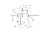
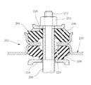
図1において、10はストラット式サスペンション装置におけるショックアブソーバの図示を省略するシリンダから上向きに突き出したピストンロッドで、12は金属製のコイルスプリングである。
14は車体パネルで、円形の開口16を有している。
18はアッパーサポート(ストラットマウント)で、ここでは主ばねとしての金属板ばね20と、補助ばねとしてのゴム弾性体22とを複合化した複合ばねにて構成してある。
Next, embodiments of the present invention will be described in detail with reference to the drawings.
In FIG. 1, 10 is a piston rod protruding upward from a cylinder (not shown) of a shock absorber in the strut suspension device, and 12 is a metal coil spring.
A
ここで金属板ばね20は、その材質がばね鋼から成っている。
ここでばね鋼としては、主としてJIS G 4801に規定するばね鋼材(SUP材)を好適に用いることができるが、他のばね鋼材、例えばJIS G 4313に規定するSUSばね材を用いることもできる。
Here, the
Here, as the spring steel, a spring steel material (SUP material) mainly defined in JIS G 4801 can be preferably used, but other spring steel materials, for example, a SUS spring material defined in JIS G 4313 can also be used.
24,26はそれぞれプレート状をなす金属製の取付ブラケットで、締結ボルト28にて車体パネル14に締結固定されるようになっている。
取付ブラケット24,26は、それぞれ同心状をなす開口30,32を有している。
上側の取付ブラケット24は、全体としてピストンロッド10の軸直角方向に平坦な形状をなしており、開口30周りの周縁部が円弧形状で上向きに湾曲しつつ立ち上がる湾曲部34とされ、また外周部が円弧形状で湾曲しつつ下向きに立ち下がる湾曲部36とされている。
The mounting
The
下側の取付ブラケット26においても、開口32周りの周縁部が円弧形状で湾曲しつつ下向きに立ち下がる湾曲部38とされ、更に外周部がテーパ形状で下向きに立ち下がる屈曲部40とされている。
この下側の取付ブラケット26は、外周側の略半部が上向きに平坦に突出した形状をなしており、その突出部42が、上側の取付ブラケット24に重ね合わされている。そしてこの突出部42の内側において、上側の取付ブラケット24と下側の取付ブラケット26との間に円環状の差込凹部44が形成されていて、そこに上記金属板ばね20の外周部が差し込まれ、それら上側の取付ブラケット24と下側の取付ブラケット26とによって保持されている。
Also in the
The
取付ブラケット24,26はスプリングシート(アッパースプリングシート)を兼ねており、その下面にゴム製のシート46を介してコイルスプリング12の上端が当接させられている。
The mounting
この実施形態において、車体の荷重は上記のアッパーサポート18を介さずに、取付ブラケット24,26を経てサスペンション装置のコイルスプリング12にて直接受けられるようになっている。
In this embodiment, the load of the vehicle body is directly received by the
金属板ばね20は、その中心部に円形の開口47を有しており、また一方、上記ゴム弾性体22は上下に2分割されていて、それぞれが平面円形状をなす上分割体48と下分割体50との間に、詳しくはここでは上分割体48の側に、円形の環状の差込溝52が形成されている。
そしてその差込溝52の内部に、金属板ばね20の内周部が差し込まれ、かかる金属板ばね20の内周部を上分割体48と下分割体50とが上下に挟み込んでいる。
The
And the inner peripheral part of the metal leaf |
即ちこの実施形態においては、金属板ばね20とゴム弾性体22とが、ピストンロッド10と車体パネル14との間において直列接続状態に配置されている。
ここで上分割体48は縦断面形状が略台形状をなしており、また一方下分割体50は縦断面形状が略逆台形状をなしている。
That is, in this embodiment, the
Here, the upper divided
ゴム弾性体22における上分割体48と下分割体50とには、中心部に上下方向の貫通孔が設けられていて、そこに金属製の剛性且つ円筒状をなすインナ部材54が嵌合状態に挿入されている。
また上分割体48の上面には金属製のプレート56が、下分割体50の下面には金属製のプレート58が、それぞれ配置されている。
ここで下側のプレート58は、ピストンロッド10の段付部59の上面に載置されている。
The upper divided
Further, a
Here, the
ピストンロッド10は、この段付部59の上側に小径の軸部60を有しており、この軸部60がプレート58の中心部の挿通孔,インナ部材54及び上側のプレート56の中心部の挿通孔を貫通して上向きに突き出している。そしてこの軸部60の上端部に形成された雄ねじ部62にナット64が螺合され、このナット64の締込みによって、ゴム弾性体22が上,下のプレート56,58により、インナ部材54とともに上下に挟み込まれる状態で、ピストンロッド10に取り付けられている。
The
本実施形態では、ショックアブソーバ即ちそのピストンロッド10を介して、アッパーサポート18に対し上下方向の振動入力が加わったとき、ゴム弾性体22と金属板ばね20とが上下方向に弾性変形する。
その際のアッパーサポート18のばね定数に対し、金属板ばね20のばね定数の寄与率が、ゴム弾性体22のばね定数の寄与率よりも大となるように、金属板ばね20及びゴム弾性体22の上下方向のばね定数が設定してある。
In this embodiment, when a vertical vibration input is applied to the
At this time, the
即ちアッパーサポート18全体のばね定数に対する金属板ばね20のばね定数の分担比率が大きく、ゴム弾性体22のばね定数の分担比率が小さくなるように、それらのばね定数が設定してあり、振動吸収に際して金属板ばね20が主ばねとして、ゴム弾性体22が補助ばねとして働くようになしてある。
That is, the spring constants of the
図2のCは、金属板ばね20のばね特性を表したもので、図示のように金属板ばね20のばね定数は、その静的ばね定数も動的ばね定数も同等で、振動周波数が高くなっても動ばね定数は上昇せず、周波数の如何に拘わらずそのばね定数は一定である。
一方ゴム弾性体22は、振動周波数が高くなるとこれに伴ってばね定数が漸次高くなり、その動的ばね定数が周波数の上昇に伴って漸次高くなっていく。
C in FIG. 2 shows the spring characteristics of the
On the other hand, the elastic constant of the rubber
前述したようにアッパーサポート18のばねをゴム弾性体単独で構成した場合、そのばね特性は図2のBのようなばね特性となる。
しかるにこの実施形態では、アッパーサポート18が金属板ばね20とゴム弾性体22との複合ばねとなしてあるため、全体のばね特性は、図2のDで示すようなばね特性となる(静的ばね定数を最も望ましい値に合せておいた場合)。
即ち金属板ばね20とゴム弾性体22との複合ばねとして構成してある本実施形態のアッパーサポート18にあっては、これをゴム弾性体単独で構成した場合に較べて、周波数の上昇に伴うばね定数の増大が抑制されている。
As described above, when the spring of the
However, in this embodiment, since the
That is, in the
図2から明らかなように、アッパーサポート18を金属板ばね20単品で構成した場合には、振動周波数が上昇してもアッパーサポート18のばね定数(上下方向のばね定数)は周波数の上昇に応じて増大せず、静的ばね定数も動的ばね定数も一定に維持される。
しかしながらそのようにした場合、振動入力が純粋に上下方向にピストンロッド10からアッパーサポート18に加わるだけであるならば、特段の支障も生じないが、ピストンロッド10からアッパーサポート18に対して、図3の矢印で示すようなこじりの入力が加わったとき、ピストンロッド10と金属板ばね20との間にゴム弾性体22が介在させてないと、ピストンロッド10からのこじりの力が直接金属板ばね20に加わってしまう。
この場合、金属板ばね20に局部的に大きな応力が集中してしまい、金属板ばね20が同部分で割れたりするなど損傷を生じてしまう恐れがある。
As can be seen from FIG. 2, when the
However, in such a case, if the vibration input is applied purely in the vertical direction from the
In this case, a large stress is locally concentrated on the
しかるに本実施形態に従ってピストンロッド10と金属板ばね20との間にゴム弾性体22を介在させておくことで、ピストンロッド10のこじりその他不規則な動きを、ゴム弾性体22の弾性変形にて吸収することができ、金属板ばね20がピストンロッド10の不規則な動きによって損傷してしまうのを有効に防止することができる。
However, the rubber
以上のように本実施形態においては、アッパーサポート18を主ばねとしての金属板ばね20と、補助ばねとしてのゴム弾性体22とを複合化した複合ばねにて構成してあることから、ゴム弾性体22単独でアッパーサポート18のばねを構成した場合に較べて、周波数の上昇に伴うばね定数(動ばね定数)の上昇の程度を小さく抑えることができる。
As described above, in the present embodiment, the
従って大振幅且つ低周波数での振動入力時におけるアッパーサポート18のばね特性を硬く設定し得て、ショックアブソーバの振動減衰力を効果的に引き出すことができ、大振幅且つ低周波数での振動入力時に車体への振動伝達を良好に抑制することができる。
Accordingly, the spring characteristic of the
一方微小振幅且つ高周波数での振動入力時には、周波数が高くなることに伴う動ばね定数の上昇を抑制し得て、動ばね定数を従来よりも小さく設定することができ、微小振幅の高周波の振動をアッパーサポート18で良好に吸収し得て、かかる高周波の振動が車体に伝わるのを効果的に抑制することができる。
On the other hand, at the time of vibration input with a small amplitude and high frequency, the increase of the dynamic spring constant accompanying the increase in frequency can be suppressed, and the dynamic spring constant can be set smaller than before, and the vibration of high frequency with a small amplitude can be set. Can be satisfactorily absorbed by the
更にこの実施形態では、金属板ばね20が車両の上下方向と直角方向である左右方向に高い剛性を有しているため、アッパーマウント18の左右剛性を効果的に高くすることができる。
Furthermore, in this embodiment, since the
図4は本発明の他の実施形態を示している。
ここではゴム弾性体22が一体加硫品となしてあり、そしてその上部94と下部96とで金属板ばね20の内周部を上下に挟み込む状態に、かかるゴム弾性体22と金属板ばね20とがゴム弾性体22の加硫成形の際に一体に加硫接着されている。
FIG. 4 shows another embodiment of the present invention.
Here, the rubber
ここで加硫成形されたゴム弾性体22は、成形時における軸方向高さが、ゴム弾性体22の中心部に設けられている貫通孔に圧入されるインナ部材54の軸方向高さよりも大きく設定されている。
このためゴム弾性体22の貫通孔にインナ部材54を圧入した状態で、ゴム弾性体22がピストンロッド10に取り付けられると、ゴム弾性体22にはその両端に設けられた上,下のプレート56,58により軸方向に予備圧縮が加えられる。
尚他の構成については上記実施形態と同様である。
The rubber
Therefore, when the rubber
In addition, about another structure, it is the same as that of the said embodiment.
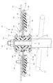
図5は更に本発明の他の実施形態を示している。
この例は、アッパーサポート18を上分割体48,下分割体50から成るゴム弾性体22と、上コイルばね66,下コイルばね68から成るコイルばねの複合ばねとして構成した例である。
ここで上コイルばね66,下コイルばね68は何れも上記のばね鋼にて形成してある。
FIG. 5 further shows another embodiment of the present invention.
In this example, the
Here, both the
ここで上コイルばね66は、ゴム弾性体22における上分割体48の上フランジ部70と下フランジ部72との間に且つ上分割体48と同心状に外挿してあり、また下コイル68は、下分割体50の上フランジ部74と下フランジ部76との間に下分割体50と同心状に外挿してある。
Here, the
この実施形態ではゴム弾性体22における上分割体48と下分割体50との間、詳しくは上分割体48の側に形成された環状の差込溝52に上記取付ブラケット24,26とは別体をなす取付ブラケット92の内周部が挿し込まれ、取付ブラケット92の内周部が上分割体48と下分割体50とにより上下方向に挟み込まれている(取付ブラケット92には中心部に開口が設けてある)。
即ちこの実施形態では上分割体48とこれに対して並列配置されている上コイルばね66、及び下分割体50とこれに対して並列配置されている下コイルばね68とが取付ブラケット92の内周部を上下に挟み込む状態にピストンロッド10に取り付けてある。
つまりこの例では上,下コイルばね66,68がゴム弾性体22に対して、並列接続状態でピストンロッド10と車体パネル14との間に介在させてある。
尚他の構成については図1に示す実施形態と同様である。
In this embodiment, an
That is, in this embodiment, the upper divided
That is, in this example, the upper and lower coil springs 66 and 68 are interposed between the
Other configurations are the same as those of the embodiment shown in FIG.
この実施形態において、上コイルばね66,下コイルばね68は、それぞれ軸方向に予圧縮を与えた状態で組み付けておくことができる。この場合ショックアブソーバのガス圧による初期撓みを軽減することができ、或いはまた振動入力時に上コイルばね66,下コイルばね68の浮上りを低減することができる。
In this embodiment, the
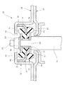
次に図6は本発明の更に他の実施形態を示している。
この実施形態は、上側の取付ブラケット24と下側の取付ブラケット26とによって、容器状を成すハウジング78を形成し、そのハウジング78の上壁部をリバウンド側の上ストッパプレート80となすとともに、底壁部をバウンド側の下ストッパプレート82となし、そしてハウジング78の内部に、ゴム弾性体22及び金属ばねとしての金属板ばね20を収容状態で配置したものである。
Next, FIG. 6 shows still another embodiment of the present invention.
In this embodiment, the upper mounting
この実施形態においても、ゴム弾性体22が上分割体48と下分割体50とに上下に2分割されており、そしてそれらの間の差込溝52内に、金属板ばね20の内周部が差し込まれ、上分割体48と下分割体50とによって金属板ばね20の内周部が上下に挟み込まれている。
この実施形態では、上分割体48に上向きに起立するリバウンド側のゴムストッパ部84が設けられ、また下分割体50にバウンド側の下向きに立ち下がる形状のゴムストッパ部86が設けられている。
Also in this embodiment, the rubber
In this embodiment, the upper divided
一方、金属板ばね20は外周部が上向きに折り曲げられて起立させられており、その起立部88がハウジング78の内面に固定されている。
ハウジング78には、上壁部80の中心部に開口90が設けられていて、この開口90にピストンロッド10の小径の軸部60が上向きに挿通されている。
尚、他の構成については上記実施形態と同様である。
この実施形態においても、基本的に図1に示す実施形態と同様の効果を奏することができる。
On the other hand, the
The
In addition, about another structure, it is the same as that of the said embodiment.
Also in this embodiment, the same effect as that of the embodiment shown in FIG. 1 can be basically obtained.
以上本発明の実施形態を詳述したが、これはあくまで一例示である。
例えば図1の実施形態では、ゴム弾性体22と金属板ばね20とが直列接続状態で配置されているが、ゴム弾性体22と金属板ばね20とを並列接続状態でピストンロッド10と車体パネル14との間に接続配置しておくといったことも可能である。
また本発明ではゴム弾性体22とコイルばねとを並列接続状態に設けるといったことも可能であり、更にゴム弾性体に対して金属ばねを直列配置するのと併せて並列に配置しておくといったことも可能である等、ゴム弾性体と金属ばねとの配置の組合せを様々な組合せとなすことができる。
Although the embodiment of the present invention has been described in detail above, this is merely an example.
For example, in the embodiment of FIG. 1, the rubber
In the present invention, the rubber
また、本発明はゴム弾性体を上例以外の他の様々な形態で構成でき、更に上記実施形態は、ショックアブソーバのピストンロッドの周りを取り囲む状態でコイルスプリング12が配置されて成るストラット式のサスペンション装置に本発明を適用した場合の例であるが、本発明はコイルスプリングがショックアブソーバのピストンロッドとは離れて非同心的に配置されて成るサスペンション装置に適用することも可能である等、本発明はその趣旨を逸脱しない範囲において種々変更を加えた形態で構成可能である。
In the present invention, the rubber elastic body can be configured in various forms other than the above examples. Furthermore, the above embodiment is a strut type in which the
10 ピストンロッド
12 コイルスプリング
18 アッパーサポート
20 金属板ばね
22 ゴム弾性体
48 上分割体
50 下分割体
66 上コイルばね
68 下コイルばね
92 取付ブラケット
94 上部
96 下部
DESCRIPTION OF
Claims (7)
前記アッパーサポートを、主ばねとしての金属ばねと補助ばねとしての前記ゴム弾性体とを複合化した複合ばねにて構成してあることを特徴とするアッパーサポート。 A coil spring and a shock absorber, and the piston rod of the shock absorber is elastically connected to the vehicle body by an upper support including a rubber elastic body as an element, while the load of the vehicle body is passed through the upper support by the coil spring. The upper support used in a vehicle suspension device of a type directly received without
The upper support is constituted by a composite spring in which a metal spring as a main spring and the rubber elastic body as an auxiliary spring are combined.
前記金属ばねとして上,下の一対のコイルばねを用い、上コイルばね,下コイルばねのそれぞれが、対応する前記ゴム弾性体の上分割体,下分割体のそれぞれとともに、前記取付ブラケットの他端側を上下に挟み込む状態に、それらゴム弾性体及びコイルばねが並列配置状態に複合化してあることを特徴とするアッパーサポート。 2. The rubber elastic body according to claim 1, wherein the rubber elastic body has an upper and lower divided structure, and the other end side of a rigid mounting bracket whose one end is fixed to the vehicle body is vertically moved by the upper and lower divided bodies of the rubber elastic body. In a state of being sandwiched, the rubber elastic body is attached to the piston rod,
A pair of upper and lower coil springs is used as the metal spring, and each of the upper coil spring and the lower coil spring has a corresponding upper and lower divided bodies of the rubber elastic body and the other end of the mounting bracket. An upper support characterized in that the rubber elastic body and the coil spring are combined in a parallel arrangement state with the side sandwiched up and down.
Priority Applications (1)
| Application Number | Priority Date | Filing Date | Title |
|---|---|---|---|
| JP2007254388A JP2009085300A (en) | 2007-09-28 | 2007-09-28 | Upper support |
Applications Claiming Priority (1)
| Application Number | Priority Date | Filing Date | Title |
|---|---|---|---|
| JP2007254388A JP2009085300A (en) | 2007-09-28 | 2007-09-28 | Upper support |
Publications (1)
| Publication Number | Publication Date |
|---|---|
| JP2009085300A true JP2009085300A (en) | 2009-04-23 |
Family
ID=40658977
Family Applications (1)
| Application Number | Title | Priority Date | Filing Date |
|---|---|---|---|
| JP2007254388A Pending JP2009085300A (en) | 2007-09-28 | 2007-09-28 | Upper support |
Country Status (1)
| Country | Link |
|---|---|
| JP (1) | JP2009085300A (en) |
Cited By (2)
| Publication number | Priority date | Publication date | Assignee | Title |
|---|---|---|---|---|
| WO2012035907A1 (en) * | 2010-09-14 | 2012-03-22 | 本田技研工業株式会社 | Damper mounting structure |
| CN109372925A (en) * | 2018-12-19 | 2019-02-22 | 中国航发控制系统研究所 | A kind of high temperature resistance and long service life metal rubber shock absorber bearing three directional loads |
-
2007
- 2007-09-28 JP JP2007254388A patent/JP2009085300A/en active Pending
Cited By (4)
| Publication number | Priority date | Publication date | Assignee | Title |
|---|---|---|---|---|
| WO2012035907A1 (en) * | 2010-09-14 | 2012-03-22 | 本田技研工業株式会社 | Damper mounting structure |
| US8668213B2 (en) | 2010-09-14 | 2014-03-11 | Honda Motor Co., Ltd. | Damper mounting structure |
| JP5521048B2 (en) * | 2010-09-14 | 2014-06-11 | 本田技研工業株式会社 | Damper mount structure |
| CN109372925A (en) * | 2018-12-19 | 2019-02-22 | 中国航发控制系统研究所 | A kind of high temperature resistance and long service life metal rubber shock absorber bearing three directional loads |
Similar Documents
| Publication | Publication Date | Title |
|---|---|---|
| JP6190651B2 (en) | Vibration isolator | |
| JP4841923B2 (en) | Strut mount | |
| JP5000235B2 (en) | Cylinder device | |
| JP5759328B2 (en) | Vibration isolator | |
| EP1800914A1 (en) | Strut mount | |
| US8678361B2 (en) | Rebound stopper of strut assembly for suspension in vehicle | |
| JP2003014035A (en) | Vibration damping device | |
| WO2013029244A1 (en) | A vibroisolating device with a nonlinear force vs. displacement characteristic and a motor vehicle suspension system comprising such vibroisolating device | |
| JP5588743B2 (en) | Suspension device | |
| JP2009108912A (en) | Dynamic damper and combination structure for dynamic damper component | |
| WO2014122842A1 (en) | Suspension mount | |
| JP2008185201A (en) | Engine mount | |
| JP2010090995A (en) | Strut mount | |
| JP2009085300A (en) | Upper support | |
| CN107627802B (en) | Suspension system buffer device for vehicle and vehicle with same | |
| JP2007127173A (en) | Bound stopper | |
| JP5313764B2 (en) | Vibration isolator | |
| JP2007064353A (en) | Swing damping device | |
| JP4303277B2 (en) | Vibration isolator | |
| CN202608501U (en) | Separation buffer type shock absorber support column and automobile | |
| JP2006057791A (en) | Mounting structure of damper | |
| JPWO2006006203A1 (en) | Strut mount | |
| JP7386638B2 (en) | Vibration isolator | |
| KR20140062628A (en) | Bush structure | |
| CN219866011U (en) | bushing assembly |