US10815744B2 - Core drilling methods and devices - Google Patents
Core drilling methods and devices Download PDFInfo
- Publication number
- US10815744B2 US10815744B2 US16/058,041 US201816058041A US10815744B2 US 10815744 B2 US10815744 B2 US 10815744B2 US 201816058041 A US201816058041 A US 201816058041A US 10815744 B2 US10815744 B2 US 10815744B2
- Authority
- US
- United States
- Prior art keywords
- drill bit
- core barrel
- core
- jet nozzles
- pressure
- Prior art date
- Legal status (The legal status is an assumption and is not a legal conclusion. Google has not performed a legal analysis and makes no representation as to the accuracy of the status listed.)
- Expired - Fee Related, expires
Links
- 238000005553 drilling Methods 0.000 title claims abstract description 108
- 238000000034 method Methods 0.000 title claims abstract description 44
- 238000005422 blasting Methods 0.000 claims abstract description 66
- 238000005299 abrasion Methods 0.000 claims abstract description 61
- 239000000463 material Substances 0.000 claims abstract description 50
- 230000007246 mechanism Effects 0.000 claims description 17
- 230000015572 biosynthetic process Effects 0.000 claims description 8
- 238000004140 cleaning Methods 0.000 claims description 4
- 239000007787 solid Substances 0.000 claims description 3
- 239000002245 particle Substances 0.000 claims description 2
- 238000007599 discharging Methods 0.000 claims 1
- 239000012530 fluid Substances 0.000 description 11
- 238000005520 cutting process Methods 0.000 description 8
- 238000010276 construction Methods 0.000 description 4
- 238000011010 flushing procedure Methods 0.000 description 4
- 230000000694 effects Effects 0.000 description 3
- 238000000227 grinding Methods 0.000 description 3
- 238000009418 renovation Methods 0.000 description 3
- 238000000926 separation method Methods 0.000 description 3
- 239000003795 chemical substances by application Substances 0.000 description 2
- 238000004519 manufacturing process Methods 0.000 description 2
- 238000003892 spreading Methods 0.000 description 2
- 230000003213 activating effect Effects 0.000 description 1
- 239000011449 brick Substances 0.000 description 1
- 239000000919 ceramic Substances 0.000 description 1
- 150000001875 compounds Chemical class 0.000 description 1
- 238000001816 cooling Methods 0.000 description 1
- 230000001419 dependent effect Effects 0.000 description 1
- 238000009826 distribution Methods 0.000 description 1
- 238000003801 milling Methods 0.000 description 1
- 239000002990 reinforced plastic Substances 0.000 description 1
- 239000011343 solid material Substances 0.000 description 1
- 230000003068 static effect Effects 0.000 description 1
- 239000004575 stone Substances 0.000 description 1
Images


Classifications
-
- E—FIXED CONSTRUCTIONS
- E21—EARTH OR ROCK DRILLING; MINING
- E21B—EARTH OR ROCK DRILLING; OBTAINING OIL, GAS, WATER, SOLUBLE OR MELTABLE MATERIALS OR A SLURRY OF MINERALS FROM WELLS
- E21B25/00—Apparatus for obtaining or removing undisturbed cores, e.g. core barrels or core extractors
- E21B25/10—Formed core retaining or severing means
-
- B—PERFORMING OPERATIONS; TRANSPORTING
- B23—MACHINE TOOLS; METAL-WORKING NOT OTHERWISE PROVIDED FOR
- B23B—TURNING; BORING
- B23B51/00—Tools for drilling machines
- B23B51/04—Drills for trepanning
- B23B51/0413—Drills for trepanning with core-cutting-off devices
-
- B—PERFORMING OPERATIONS; TRANSPORTING
- B26—HAND CUTTING TOOLS; CUTTING; SEVERING
- B26D—CUTTING; DETAILS COMMON TO MACHINES FOR PERFORATING, PUNCHING, CUTTING-OUT, STAMPING-OUT OR SEVERING
- B26D7/00—Details of apparatus for cutting, cutting-out, stamping-out, punching, perforating, or severing by means other than cutting
- B26D7/18—Means for removing cut-out material or waste
- B26D7/1845—Means for removing cut-out material or waste by non mechanical means
-
- B—PERFORMING OPERATIONS; TRANSPORTING
- B28—WORKING CEMENT, CLAY, OR STONE
- B28D—WORKING STONE OR STONE-LIKE MATERIALS
- B28D1/00—Working stone or stone-like materials, e.g. brick, concrete or glass, not provided for elsewhere; Machines, devices, tools therefor
- B28D1/02—Working stone or stone-like materials, e.g. brick, concrete or glass, not provided for elsewhere; Machines, devices, tools therefor by sawing
- B28D1/04—Working stone or stone-like materials, e.g. brick, concrete or glass, not provided for elsewhere; Machines, devices, tools therefor by sawing with circular or cylindrical saw-blades or saw-discs
- B28D1/041—Working stone or stone-like materials, e.g. brick, concrete or glass, not provided for elsewhere; Machines, devices, tools therefor by sawing with circular or cylindrical saw-blades or saw-discs with cylinder saws, e.g. trepanning; saw cylinders, e.g. having their cutting rim equipped with abrasive particles
-
- E—FIXED CONSTRUCTIONS
- E21—EARTH OR ROCK DRILLING; MINING
- E21B—EARTH OR ROCK DRILLING; OBTAINING OIL, GAS, WATER, SOLUBLE OR MELTABLE MATERIALS OR A SLURRY OF MINERALS FROM WELLS
- E21B10/00—Drill bits
- E21B10/02—Core bits
-
- E—FIXED CONSTRUCTIONS
- E21—EARTH OR ROCK DRILLING; MINING
- E21B—EARTH OR ROCK DRILLING; OBTAINING OIL, GAS, WATER, SOLUBLE OR MELTABLE MATERIALS OR A SLURRY OF MINERALS FROM WELLS
- E21B10/00—Drill bits
- E21B10/02—Core bits
- E21B10/04—Core bits with core destroying means
-
- E—FIXED CONSTRUCTIONS
- E21—EARTH OR ROCK DRILLING; MINING
- E21B—EARTH OR ROCK DRILLING; OBTAINING OIL, GAS, WATER, SOLUBLE OR MELTABLE MATERIALS OR A SLURRY OF MINERALS FROM WELLS
- E21B41/00—Equipment or details not covered by groups E21B15/00 - E21B40/00
- E21B41/0078—Nozzles used in boreholes
-
- B—PERFORMING OPERATIONS; TRANSPORTING
- B08—CLEANING
- B08B—CLEANING IN GENERAL; PREVENTION OF FOULING IN GENERAL
- B08B9/00—Cleaning hollow articles by methods or apparatus specially adapted thereto
- B08B9/02—Cleaning pipes or tubes or systems of pipes or tubes
- B08B9/027—Cleaning the internal surfaces; Removal of blockages
- B08B9/04—Cleaning the internal surfaces; Removal of blockages using cleaning devices introduced into and moved along the pipes
- B08B9/043—Cleaning the internal surfaces; Removal of blockages using cleaning devices introduced into and moved along the pipes moved by externally powered mechanical linkage, e.g. pushed or drawn through the pipes
- B08B9/045—Cleaning the internal surfaces; Removal of blockages using cleaning devices introduced into and moved along the pipes moved by externally powered mechanical linkage, e.g. pushed or drawn through the pipes the cleaning devices being rotated while moved, e.g. flexible rotating shaft or "snake"
-
- B—PERFORMING OPERATIONS; TRANSPORTING
- B24—GRINDING; POLISHING
- B24C—ABRASIVE OR RELATED BLASTING WITH PARTICULATE MATERIAL
- B24C1/00—Methods for use of abrasive blasting for producing particular effects; Use of auxiliary equipment in connection with such methods
- B24C1/04—Methods for use of abrasive blasting for producing particular effects; Use of auxiliary equipment in connection with such methods for treating only selected parts of a surface, e.g. for carving stone or glass
-
- B—PERFORMING OPERATIONS; TRANSPORTING
- B26—HAND CUTTING TOOLS; CUTTING; SEVERING
- B26F—PERFORATING; PUNCHING; CUTTING-OUT; STAMPING-OUT; SEVERING BY MEANS OTHER THAN CUTTING
- B26F1/00—Perforating; Punching; Cutting-out; Stamping-out; Apparatus therefor
- B26F1/26—Perforating by non-mechanical means, e.g. by fluid jet
-
- B—PERFORMING OPERATIONS; TRANSPORTING
- B26—HAND CUTTING TOOLS; CUTTING; SEVERING
- B26F—PERFORATING; PUNCHING; CUTTING-OUT; STAMPING-OUT; SEVERING BY MEANS OTHER THAN CUTTING
- B26F3/00—Severing by means other than cutting; Apparatus therefor
- B26F3/004—Severing by means other than cutting; Apparatus therefor by means of a fluid jet
-
- E—FIXED CONSTRUCTIONS
- E03—WATER SUPPLY; SEWERAGE
- E03F—SEWERS; CESSPOOLS
- E03F9/00—Arrangements or fixed installations methods or devices for cleaning or clearing sewer pipes, e.g. by flushing
- E03F9/002—Cleaning sewer pipes by mechanical means
Definitions
- the present disclosure relates to core drilling devices and methods.
- Drill bits are known as the tools of a drill, with which a ring-shaped hole is cut into solid material, for instance concrete, natural stone, brick, ceramic, or other materials, the centrally remaining drilling core is then detached from the material and is removed from the hole.
- the drill bit comprises a hollow-cylindrical body referred to as a core barrel.
- the core barrel has cutting elements or grinding elements distributed across the surface of its front end, which, with regard to material, shape, and distribution, are suitable for the abrasion of material to the required extent and in the required way.
- the cutting elements and the grinding elements shall generally be referred to as abrasion elements.
- the abrasion elements can be arranged on the circular covering surface of the core barrel and/or on a suitably long front section of the inner and/or outer surface of the core barrel.
- the rear end of the drill bit can be connected, using a suitable connector, to the tool holding fixture of an external supply unit of the drilling unit, which is used by the drill bit.
- the supply unit and further components of the drilling unit, which serve the running and the operating of the drilling unit, are adapted to the respective application and are not part of the drill bit itself.
- the connector is designed with regards to the tool holding fixture, so that the drill bit can be operated and, in particular, rotated at the desired speed.
- the geometry and the materials of the core barrel and of the abrasion elements of the drill bit are designed with regards to the material to be drilled into and the size as well as the depth of the hole.
- Known drill bits can produce drilled holes of only a few centimeters up until several 10 centimeters and more.
- a flushing agent flows into the drilled hole through the core barrel and/or along the outside of the core barrel, so that the removed drilling material can be flushed away and the drill bit can be cooled.
- the removal of the drilling core or sections thereof from the drilled hole can be carried out in different ways. Often, the core is broken mechanically or through its own weight into small sections, which can be removed more easily, such as by a flushing agent. With an increasing diameter of the drilling core, the breaking of the drilling core can become increasingly uncontrollable as well as difficult and more often necessary, so that the result and efficiency of the core drilling can become inadequate, or a lengthy hole milling is carried out instead of a core drilling since the drilling core cannot be dealt with. The latter is known, e.g., from duct renovations, if a duct, which can sometimes extend over several meters, needs to be shut completely.
- the method and the drill bit shall be usable for drillings that are not vertical, for instance for almost horizontal drillings such as for carrying out duct renovations.
- the present disclosure relates to methods for the execution of core drillings into a material using a drill, which utilizes a core drill bit.
- the present disclosure also relates to drill bits, which are designed as a hollow cylindrical core barrel and which have abrasion elements at the front of the core barrel, which serve the abrasion of material and which are attached to the surface of the core barrel in an annular manner.
- the present disclosure further relates to devices for the removal of adherences on the inner surface of channels (ducts), which also have such a drill bit, by high-pressure blasting.
- a high pressure for the blasting medium may be pressures which range from approximately 80 bar to approximately 6000 bar and therefore may lie considerably above those pressures used for wet drillings.
- pumps are known, which are used to achieve a fluid pressure of up to 6000 bar, but such extreme pressures can create limitations through the medium supply to the nozzles.
- Such extreme pressures are used, for instance, with stationary fluid blasting devices, which are used for the separation or cutting of hard materials.
- fluid guides such as reinforced plastic hoses
- the upper limit of the maximum of the fluid that can be directed through this flexible fluid guide is currently approximately 3000 bar.
- higher pressures may also be possible and may be used for the purpose of the methods and devices described in the following.
- the method and the devices to be used therewith are also particularly suitable for the use of a maximum pressure, so that the subsequent mention of high pressure also includes the use of a maximum pressure.
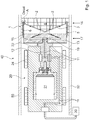
- FIG. 1 is a cross-sectional view of an example drill bit with a drilling unit, using the example of a duct renovation device.
- FIG. 2A is a detailed illustration of an example front end of a drill bit of FIG. 1 .
- FIG. 2B is a detailed illustration of another example front end of a drill bit.
- FIG. 3 is a front view of an example of a drill bit.
- FIG. 4A is a cross-sectional view of another example of a drill bit.
- FIG. 4B is a cross-sectional view of another example of a drill bit.
- a drill bit which is designed as a hollow cylindrical base body, subsequently referred to as a core barrel, and which has abrasion elements at the front end of the core barrel, which serves the abrasion of material.
- the abrasion elements may be cutting elements or grinding elements or other elements which are suitable for the abrasion of material. They are attached across the front edge of the surface of the core barrel, so that they form a ring of abrasion elements, which is positioned at the front end of the drill bit and covers the front face of the drill bit.
- abrasion elements may be arranged on a narrow front ring of the outer surface, optionally also on the inner surface.
- front and ‘rear’ or rather ‘front face’ and ‘rear face’ or analogous terms refer to the direction of the mechanical abrasion of material and therefore coincide with the axis of the drilling core and drill bit.
- the rear end of the drill bit which lies opposite the front end, is made up of an end plate, which closes the drill bit at the rear and which can be designed in different ways. For instance, it may be circular or annular or shaped differently, so that it can ensure the stability of the drill bit as well as the rotation and the forwards motion of the drill bit into the emerging hole.
- a suitable connector is arranged at the end plate or the core barrel, which are suitable for the production of a mechanical connection to a supply unit of the drilling unit.
- the connection to the supply unit is such that the drill bit can be rotated.
- different connectors are suitable, such as nozzles, bearings, flanges, or others.
- the drill bit has at least two, optionally also more, high-pressure jet nozzles. These are connected with a suitable high pressure source through a suitable connector, which provides a blasting medium under a high pressure, if necessary also under maximum pressure, and which directs the blasting medium via the connectors to the high-pressure jet nozzles.
- a nozzle is a tubular device guiding a fluid, which has a tapered cross-section towards the nozzle outlet to increase the speed of the fluid.
- a nozzle is referred to as a jet nozzle, which has one or more openings for the generation of a high pressure jet from a blasting medium which is under a high or maximum pressure, so that the high pressure jet follows a directed jet path.
- a jet path is understood in this case as the central axis of the jet, which indicates the predominant direction of the spreading of the fluid and typically is determined through the axis of the tubular portion of the nozzle.
- solid particles may be added to the blasting medium to enhance the abrasive effect.
- such high-pressure jet nozzles are suitable, which provide the desired jet shape, for instance fan-shaped, bundled, multiple jets, or other shapes, or enable a variation of the jet shape and which are adapted to the used blasting medium as well as the used pressure.
- the high-pressure jet nozzles are arranged in such a way that none of the high-pressure jet nozzles extend beyond the internal radius of the abrasion elements, in this case referred to as internal ring radius, i.e., they do not have a smaller distance to the axis of the core barrel than the abrasion elements. Otherwise, the high-pressure jet nozzles would collide with the drilling core during the drilling. From a construction point of view, this can be realized in different ways.
- the high-pressure jet nozzles may be countersunk in the inner surface of the core barrel, so that they do not protrude above the inner surface.
- the internal ring radius may be smaller than the internal radius of the core barrel, so that the jet nozzles may protrude above the inner surface of the core barrel by an amount which is smaller than the difference between the internal tube (barrel/pipe) radius and the internal ring radius.
- the high-pressure jet nozzles are directed towards the inside of the core barrel in order to abrade material at that point of the drilling core by dividing the drilling core into the defined sections or destroying it or by combining both variations of processing the drilling core with each other.
- the location and extent of the abrasion of material may be influenced.
- the jet direction of the high-pressure jet nozzles may be varied in order to adapt the abrasion of material to the respective application.
- the jet shape may be taken into account besides the location and the extent of the abrasion of material.
- the variation of these parameters allows very different executions of the abrasion of material and the consideration of further conditions of the method to be executed.
- the high-pressure jet nozzles may be oriented in such a way that the blasting only blasts onto the inner surface of the core barrel. In this way, it is ensured that if the jet penetrates the material to be abraded, damage to the wall of a duct behind is excluded.
- the drill bit may have outflows, whereby these are coordinated with the inlets of the blasting medium at or in the core barrel.
- the outflows are designed and arranged according to the amount and the viscosity of the overburden, a compound of abraded material and blasting medium. For instance, an opening or several thereof may be installed in the end plate. Alternatively or additionally, openings may also be arranged in the core barrel.
- the removal of the overburden may be aided by channel-like recesses in the outer surface of the core barrel. In these recesses, the removal of the overburden is aided outside the drill bit.
- openings in the core barrel may end in these recesses and/or the recesses may run in a spiral pattern.
- the inlets to the high-pressure jet nozzles may be realized as channels in the wall of the core barrel.
- Such an inlet construction which is installed in a solid component, has the advantage, specifically with respect to a blasting medium under high pressure, that rigid or interference-prone inlets can be avoided.
- rotary feedthroughs a static inlet may be realized in a component/part that can be rotated.
- the inlets are directed through or into the end plate to high-pressure jet nozzles arranged at this point.
- the inlets of the blasting medium may additionally or alternatively be arranged outside the wall.
- the differences between the internal ring radius or the external ring radius and the internal core barrel radius or the external core barrel radius, respectively, permit the formation of a sufficient distance between the wall of the drilling core or the drilled hole and the internal or external wall of the core barrel, respectively.
- the inlets of the blasting medium to the jet nozzles may for instance be arranged on the wall of the core barrel.
- the drill bit In order to carry out the method of core drilling, the drill bit is rotated about the axis of the drill bit by a drive unit, usually the drive unit of the external supply unit, and a forward motion is carried out. As a result, an annular abrasion of material occurs, which corresponds to the ring of the abrasion elements at the front end of the drill bit. With an advancing forward and continuous rotary motion, a cylindrical drilling core is formed, which increasingly protrudes into the core barrel.
- jets of the blasting medium which is under high pressure, may be generated by the high-pressure jet nozzles of the drill bit and may be directed into the interior of the drill bit and thus towards the drilling core.
- material is removed from the drilling core as soon as the abrasive jets hit the drilling core.
- the material detached from the drilling core mixes with the blasting medium and is transported from the drilling core into the existing channel by the outflows described above.
- the abrasion of material may be achieved to the desired extent and the desired shape.
- the bundling of the jet and thus, the intensity and the extent, i.e., the depth and surface, of the abrasion generated by a jet, for instance, may be varied. Similar may be achieved through the number and position of the high-pressure jet nozzles. In this way, the abrasion may occur on a large surface or at chosen locations through an even effect of the jets of several distributed high-pressure jet nozzles.
- one or more high-pressure jet nozzles may be arranged on the inner surface of the core barrel behind the abrasion elements. If their jets are directed onto the axis of the drilling core, given that the jet directions have an, or rather the same, angle ⁇ in the range of ⁇ 45° to +45° in relation to the normal of the inner surface at the nozzle outlet, a gap may be inserted all around into the drilling core, which can be directed to the drilling core center and thus lead to the separation of a section of the drilling core. For this purpose, the drilling process is completed, or at least the advancing drive of the drill bit is stopped, after reaching the desired length of the drilling core, and a cut is made into the drilling core by the jet nozzles and the blasting medium under high or maximum pressure.
- the core barrel may have a holding mechanism that holds the drilling core.
- the holding mechanism can hold the drilling core from the end plate or the core barrel.
- springs or a press pad or several thereof may be arranged at the inner surface.
- the press pads expand in the direction of the drilling core as they are filled with a fluid, that is the blasting medium or another fluid, and press against the drilling core.
- the blasting medium being applied at the drill bit allows, for instance, a press pad or several thereof to be filled.
- a press pad may be used for such a press pad.
- the holding force to be applied may be varied by means of contact pressure and contact surface.
- grooves which are arranged differently, may be inserted in the drilling core, in which the holding means can have access to, by a ring of high-pressure jet nozzles or an individual high-pressure jet nozzle.
- the high-pressure jet nozzles may be directed to a large area towards the rear part of the drilling core, i.e., its free end, with such a rate of abrasion, so that the drilling core may be abraded continuously.
- the abrasion progress may correspond to the advancing drive of the drill bit according to the mechanical abrasion.
- the mechanical abrasion of material at the front end of the core barrel may be complemented by an abrasion using a blasting medium.
- a blasting medium For this purpose, at least one high-pressure jet nozzle may be arranged at the front face of the core barrel and may be aligned with the drilling direction. The orientation also may deviate from the drilling direction by a few degrees, resulting in a wider annular gap and narrower drilling core.
- the intensity and width of abrasion by the blasting medium also depend on the application in this instance.
- jet nozzles together with the blasting medium, alternatively also a flushing medium with a reduced pressure of a maximum pressure of a few bar (e.g., 10 bar), may be used for cooling and/or flushing.
- the described method may be used for earth drilling in geology, geothermal energy, construction, or other applications where both vertical and horizontal drilled holes are required.
- One application is, for instance, the opening up of complete or partial closures of closed channels (ducts) that formed as a result of adherences on their inner surface.
- closed channels ducts
- channel cutters instead of using channel cutters to completely remove the material clogging the channel, only annular holes with an outer diameter equal to or slightly smaller than the inner diameter of the channel are drilled with the drill bit described and the remaining drilling core is removed. This reduces the effort for such a channel opening considerably.
- the drill bit is operated for this purpose using a channel (duct) cleaning device, by which the advancing drive and the rotation of the drill bit is carried out and the blasting medium, which is under a high pressure, is added.
- a channel (duct) cleaning device by which the advancing drive and the rotation of the drill bit is carried out and the blasting medium, which is under a high pressure, is added.
- Such a device comprises the above described drill bit at its front end, a suitable mechanism for moving and positioning of the drill bit in the channel (duct), as well as a medium inlet for the supply of the blasting medium, which is under a high pressure, to the high-pressure jet nozzles.
- Various designs are suitable as moving mechanisms, for instance hand-operated or machine-operated feed rods or towing devices. Remote-controlled carriages or other designs also may be used. It is apparent that the moving mechanism as well as the drill bit, are designed in such a way that both can be positioned and moved at least along one side at a distance from the wall of the channel (duct).
- a drill bit 1 has a hollow cylindrical core barrel 5 with an axis.
- abrasion elements 4 are fixed on a front face 9 of the core barrel 5 , so that there is a circular arrangement of abrasion elements 4 on the front face 9 .
- one or more jet nozzles 2 is/are arranged on the front face 9 .
- at least one of the jet nozzles 2 is oriented in a direction of drilling and/or is configured to generate high-pressure jets of a blasting medium 3 in the direction of drilling.
- an end plate 13 is arranged, as illustrated in FIG. 1 .
- the end plate 13 has a central recess 15 , which serves as a connector for the formation of a mechanical connection to a supply unit 20 of a drilling unit 40 (also referred to herein as device 40 ) arranged behind the drill bit 1 , on its surface which faces away from the core barrel 5 .
- the supply unit 20 serves to move the drill bit 1 , supply blasting medium 3 , supply power to the drive unit 21 , and control the drive unit.
- a shaft 12 ends in the recess 15 of the drill bit and is mounted to the end plate 13 with a flange 22 .
- the shaft 12 transmits a rotary motion of drive unit 21 of supply unit 20 to the end plate 13 of the drill bit 1 .
- the drive unit 21 can make use of a different driving mechanism, for instance electric, hydraulic, or others.
- the end plate 13 further has two high-pressure jet nozzles 2 , whose blasting directions (presented as dashed line) are directed towards an inner surface 6 of the core barrel 5 at a flat angle measured in relation to the surface of the end plate 13 .
- the jet nozzles 2 are countersunk in the surface of the end plate 13 in order to ensure an unhindered jet spreading even at such a flat angle.
- the jet nozzles 2 are connected to a high-pressure source 30 of blasting medium 3 .
- Inlets 11 of the high-pressure source 30 to the jet nozzles 2 run in channels or lines through the supply unit 20 , through its shaft 12 , over a central distributor 19 in the end plate 13 to the high-pressure jet nozzles 2 .
- Other realizations of the inlets 11 and of the connection to the high-pressure source 30 are possible.
- FIG. 3 presents a first view into the drill bit 1 .
- Both jet nozzles 2 are arranged in the end plate 13 in a radial manner and opposite each other.
- the end plate has four evenly distributed circular segments, which form outflows 14 for overburden generated in the drill bit (not shown).
- the outflows 14 are realized as openings running through the end plate 13 .
- Device 40 may be configured to remove adherences at the inner surface of channels 50 , specifically closed channels (ducts).
- device 40 also may be referred to as channel cleaning device 40 .
- the supply unit 20 may have a suitable moving mechanism 24 , such as wheels, chains, runners, or others. If the drill bit 1 , as shown in FIG. 1 , is larger than the supply unit in regards to at least one dimension, suitable measures can be taken to center the drill bit 1 in the channel (duct). Suitable ways to keep the distance may be used or the moving mechanism may be arranged in such a way around the device that a centering, using the moving mechanism, may be carried out.
- FIGS. 4A and 4B present alternative embodiments of drill bit 1 .
- the drill bit has several jet nozzles 2 for the blasting medium 3 , which are arranged in a distributed manner on a circumference of the inner surface 6 of the core barrel 5 behind the abrasion elements 4 (schematically shown as a block) when seen from the front end of the drill bit.
- the arrangement of the jet nozzles 2 shall be referred to as nozzle ring in the following discussion.
- Their blasting direction runs into the hollow cylinder of the core barrel 5 .
- the blasting direction of the jet nozzles may be perpendicular to the surface of the inner surface 6 in the direction of an axis 7 of the core barrel 5 .
- the angle orientation of the blasting direction may be varied by the jet nozzles.
- the jet nozzles 2 are arranged in such a way that none of the jet nozzles 2 extend beyond the internal radius of the abrasion elements 4 , i.e., they are at a smaller distance to the axis 7 of the core barrel than the abrasion elements. Otherwise, the jet nozzles 2 would collide with a drilling core 8 during the drilling. From a construction point of view, this can be realized in different ways.
- the jet nozzles 2 may be countersunk in the inner surface 6 of the core barrel 5 , so that they do not extend beyond the inner surface 6 .
- the internal diameter of the ring of the abrasion elements 4 may be smaller than the internal diameter of the core barrel 5 (internal core barrel diameter, corresponding to the internal core barrel radius R RS ), so that the jet nozzles may extend beyond the inner surface 6 of the core barrel 5 to an extent, which is smaller than the difference between the internal tube radius and the internal ring radius R SI .
- the high-pressure jets of a blasting medium 3 with an abrasive effect which are distributed over the circumference and directed towards the axis 7 of the drill bit 1 , allow to cut the drilling core 8 at a desired length, at a maximum of an internal free length of the drill bit 1 .
- the distance of the nozzle ring to the front end of 16 of the drill bit 1 thereby defines the maximum cutting length of the drill bit 1 .
- the nozzle ring is arranged at the front end of the core barrel 5 as close as possible behind the abrasion elements 4 . A larger distance to the front end 16 or several nozzle rings are possible as an alternative.
- holding mechanism 18 for instance leaf springs, are arranged, which are suitable for holding and/or fixing the drilling core 8 with such a force that the drilling core 8 can be removed from drilled hole 10 using the drill bit 1 . It is apparent that the force to be applied and, corresponding to this, the suitable holding mechanism 18 depend on the size, weight, and stability of the drilling core 8 .
- the drill bit 1 has a shaft 12 through which the drill bit may be mechanically connected to a suitable drilling unit (e.g., device 40 ).
- the inlet 11 of the blasting medium to the high-pressure jet nozzles 2 runs in channels through the shaft 12 and the wall of the core barrel 5 .
- the drill bit 1 in addition has outflows (not shown) for the removal of the overburden as presented in the general description.
- the drill bit 1 includes channel-like recesses 23 in the outer surface of core barrel 5 that are configured to aid in the removal of the overburden.
- the controlling of the rotation of the drill bit and the drive unit of the drilling unit as well as the controlling of the blasting medium may occur using a suitable control unit (not shown).
- a suitable control unit not shown
- the surroundings of the device may be captured using a camera.
- a drill bit comprising:
- a core barrel with an axis A and a front end and a rear end, which is opposite to the front end; whereby the core barrel has abrasion elements, which are fixed at the front end on the surface of the core barrel distributed in a circular manner, and whereby, at the rear end of the core barrel, an end plate is arranged;
- a device for the removal of adherences at inner surfaces of channels by high-pressure blasting comprising:
- the moving mechanism and the drill bit both can be positioned and moved at least along one side at a distance to a wall of the channel.
Landscapes
- Engineering & Computer Science (AREA)
- Life Sciences & Earth Sciences (AREA)
- Mining & Mineral Resources (AREA)
- Geology (AREA)
- Mechanical Engineering (AREA)
- Physics & Mathematics (AREA)
- Environmental & Geological Engineering (AREA)
- Fluid Mechanics (AREA)
- General Life Sciences & Earth Sciences (AREA)
- Geochemistry & Mineralogy (AREA)
- Forests & Forestry (AREA)
- Processing Of Stones Or Stones Resemblance Materials (AREA)
Applications Claiming Priority (3)
| Application Number | Priority Date | Filing Date | Title |
|---|---|---|---|
| DE102017117963 | 2017-08-08 | ||
| DE102017117963 | 2017-08-08 | ||
| DE102017117963.1 | 2017-08-08 |
Publications (2)
| Publication Number | Publication Date |
|---|---|
| US20190048674A1 US20190048674A1 (en) | 2019-02-14 |
| US10815744B2 true US10815744B2 (en) | 2020-10-27 |
Family
ID=63244402
Family Applications (1)
| Application Number | Title | Priority Date | Filing Date |
|---|---|---|---|
| US16/058,041 Expired - Fee Related US10815744B2 (en) | 2017-08-08 | 2018-08-08 | Core drilling methods and devices |
Country Status (4)
| Country | Link |
|---|---|
| US (1) | US10815744B2 (pl) |
| EP (1) | EP3441207B1 (pl) |
| DK (1) | DK3441207T3 (pl) |
| PL (1) | PL3441207T3 (pl) |
Cited By (1)
| Publication number | Priority date | Publication date | Assignee | Title |
|---|---|---|---|---|
| US11573156B2 (en) * | 2019-01-15 | 2023-02-07 | Westinghouse Electric Company Llc | Minimally invasive microsampler for intact removal of surface deposits and substrates |
Families Citing this family (11)
| Publication number | Priority date | Publication date | Assignee | Title |
|---|---|---|---|---|
| CN109915049B (zh) * | 2019-04-10 | 2021-11-30 | 中国石油大学胜利学院 | 一种密闭式油井清洗器 |
| CN111929157A (zh) * | 2020-07-20 | 2020-11-13 | 河南景链新材料有限公司 | 一种叶蜡石块的性能检测方法 |
| CN112588736B (zh) * | 2020-11-25 | 2022-05-06 | 山西绿洁环保有限公司 | 一种污水管道表面处理工艺 |
| CN113267376B (zh) * | 2021-07-01 | 2023-05-30 | 上饶师范学院 | 一种地质检测仪器 |
| CN114961614B (zh) * | 2022-05-17 | 2023-11-10 | 煤炭科学研究总院有限公司 | 一种矿山巷道开采钻进装置 |
| CN114991674B (zh) * | 2022-06-22 | 2023-08-29 | 中国电建集团华东勘测设计研究院有限公司 | 一种用于冻土层勘探的快速组装自动取样钻具 |
| CN115246137B (zh) * | 2022-08-16 | 2024-05-07 | 南京塞维机械科技有限公司 | 一种环保原材料提取设备 |
| CN115726718A (zh) * | 2022-11-23 | 2023-03-03 | 沈良建 | 一种用于钻芯法的防崩坏多级混凝土钻芯装置 |
| CN115680650B (zh) * | 2022-11-28 | 2024-12-10 | 中冶成都勘察研究总院有限公司 | 一种岩芯信息快速获取的钻进方法 |
| CN116044335B (zh) * | 2023-02-15 | 2023-09-01 | 浙江华展研究设计院股份有限公司 | 一种地质建模用钻孔数据采集装置 |
| CN116065994A (zh) * | 2023-03-29 | 2023-05-05 | 德州鸿途矿山机械有限公司 | 一种矿山岩石钻进取样设备及取样方法 |
Citations (14)
| Publication number | Priority date | Publication date | Assignee | Title |
|---|---|---|---|---|
| US1512140A (en) * | 1923-07-09 | 1924-10-21 | Schaub Otto | Rock boring |
| US2034073A (en) * | 1934-04-02 | 1936-03-17 | Globe Oil Tools Co | Well bit |
| US2084686A (en) | 1935-06-21 | 1937-06-22 | Frank L Howard | Sample taking machine |
| GB686778A (en) | 1950-02-15 | 1953-01-28 | Prec Diamond Products Ltd | Improvements in or relating to the ejection of slugs from tubular diamond drills |
| US2724575A (en) * | 1952-12-10 | 1955-11-22 | Exxon Research Engineering Co | Pellet impact core drill |
| US2975849A (en) * | 1958-04-25 | 1961-03-21 | Diamond Oil Well Drilling | Core disintegrating drill bit |
| US3112800A (en) * | 1959-08-28 | 1963-12-03 | Phillips Petroleum Co | Method of drilling with high velocity jet cutter rock bit |
| US5016718A (en) * | 1989-01-26 | 1991-05-21 | Geir Tandberg | Combination drill bit |
| US5439067A (en) * | 1994-08-08 | 1995-08-08 | Dresser Industries, Inc. | Rock bit with enhanced fluid return area |
| JPH1044133A (ja) | 1996-07-31 | 1998-02-17 | Mitsubishi Heavy Ind Ltd | コアカッタ |
| JP2000291370A (ja) | 1999-04-12 | 2000-10-17 | Nippon Kiso Gijutsu:Kk | サンプリング装置及び方法並びに地盤サンプリング用ビット及びコアリフターケース |
| EP2295709A1 (en) | 2009-08-21 | 2011-03-16 | Welltec A/S | Downhole tool head for mounting onto a downhole tool for releasing of precipitated solids |
| CN106907121A (zh) | 2017-04-21 | 2017-06-30 | 中国矿业大学 | 一种自动分段排渣与截断岩芯的取芯系统及其使用方法 |
| EP3305425A1 (en) | 2016-07-29 | 2018-04-11 | Beijing China Base Startrade Co., Ltd | Portable battery steam cleaner |
-
2018
- 2018-08-08 EP EP18187919.8A patent/EP3441207B1/de active Active
- 2018-08-08 US US16/058,041 patent/US10815744B2/en not_active Expired - Fee Related
- 2018-08-08 PL PL18187919T patent/PL3441207T3/pl unknown
- 2018-08-08 DK DK18187919.8T patent/DK3441207T3/da active
Patent Citations (15)
| Publication number | Priority date | Publication date | Assignee | Title |
|---|---|---|---|---|
| US1512140A (en) * | 1923-07-09 | 1924-10-21 | Schaub Otto | Rock boring |
| US2034073A (en) * | 1934-04-02 | 1936-03-17 | Globe Oil Tools Co | Well bit |
| US2084686A (en) | 1935-06-21 | 1937-06-22 | Frank L Howard | Sample taking machine |
| GB686778A (en) | 1950-02-15 | 1953-01-28 | Prec Diamond Products Ltd | Improvements in or relating to the ejection of slugs from tubular diamond drills |
| US2724575A (en) * | 1952-12-10 | 1955-11-22 | Exxon Research Engineering Co | Pellet impact core drill |
| US2975849A (en) * | 1958-04-25 | 1961-03-21 | Diamond Oil Well Drilling | Core disintegrating drill bit |
| US3112800A (en) * | 1959-08-28 | 1963-12-03 | Phillips Petroleum Co | Method of drilling with high velocity jet cutter rock bit |
| US5016718A (en) * | 1989-01-26 | 1991-05-21 | Geir Tandberg | Combination drill bit |
| US5439067A (en) * | 1994-08-08 | 1995-08-08 | Dresser Industries, Inc. | Rock bit with enhanced fluid return area |
| US5439067B1 (en) * | 1994-08-08 | 1997-03-04 | Dresser Ind | Rock bit with enhanced fluid return area |
| JPH1044133A (ja) | 1996-07-31 | 1998-02-17 | Mitsubishi Heavy Ind Ltd | コアカッタ |
| JP2000291370A (ja) | 1999-04-12 | 2000-10-17 | Nippon Kiso Gijutsu:Kk | サンプリング装置及び方法並びに地盤サンプリング用ビット及びコアリフターケース |
| EP2295709A1 (en) | 2009-08-21 | 2011-03-16 | Welltec A/S | Downhole tool head for mounting onto a downhole tool for releasing of precipitated solids |
| EP3305425A1 (en) | 2016-07-29 | 2018-04-11 | Beijing China Base Startrade Co., Ltd | Portable battery steam cleaner |
| CN106907121A (zh) | 2017-04-21 | 2017-06-30 | 中国矿业大学 | 一种自动分段排渣与截断岩芯的取芯系统及其使用方法 |
Non-Patent Citations (4)
| Title |
|---|
| English-language machine translation of Chinese Patent Application Publication No. CN 106907121 A, Jun. 30, 2017. |
| English-language machine translation of European Patent Application Publication No. EP 3 305 425 A1, Apr. 11, 2018. |
| English-language machine translation of Japanese Patent Application Publication No. JP 2000-291370 A, Oct. 17, 2000. |
| English-language machine translation of Japanese Patent Application Publication No. JP H10-44133 A, Feb. 17, 1998. |
Cited By (1)
| Publication number | Priority date | Publication date | Assignee | Title |
|---|---|---|---|---|
| US11573156B2 (en) * | 2019-01-15 | 2023-02-07 | Westinghouse Electric Company Llc | Minimally invasive microsampler for intact removal of surface deposits and substrates |
Also Published As
| Publication number | Publication date |
|---|---|
| US20190048674A1 (en) | 2019-02-14 |
| PL3441207T3 (pl) | 2020-12-14 |
| DK3441207T3 (da) | 2020-08-10 |
| EP3441207B1 (de) | 2020-05-13 |
| EP3441207A1 (de) | 2019-02-13 |
Similar Documents
| Publication | Publication Date | Title |
|---|---|---|
| US10815744B2 (en) | Core drilling methods and devices | |
| JP5033257B1 (ja) | シールドトンネル掘進機 | |
| EP3516153B1 (en) | Rock cutting device | |
| CN112196543B (zh) | 一种掘进机及其磨料射流辅助破岩装置 | |
| JP5932958B2 (ja) | 穴明け工具支持体及びカラーリング方法 | |
| JPH1030392A (ja) | 指向性ボーリング法及び装置 | |
| RU2007131213A (ru) | Способ и устройство для выполнения скважин в грунте | |
| JPS63593A (ja) | 流体掘削装置および流体掘削方法 | |
| JP7084928B2 (ja) | 4つの削孔体を備えたボーリング機械 | |
| KR20140050112A (ko) | 실드 굴진기의 굴삭비트 교환장치 | |
| JP4783849B2 (ja) | シールドトンネル掘進機 | |
| JP4205706B2 (ja) | 土壌中に溝壁を形成する方法と溝壁掘削装置 | |
| US12571263B2 (en) | Expanding drill device | |
| US20160053571A1 (en) | Method for lining boreholes for deep bores and device for carrying out said method | |
| CA2663645A1 (en) | Full-cut heading machine | |
| KR100770243B1 (ko) | 레이저 노즐을 구비한 터널 굴진기 | |
| KR101618968B1 (ko) | 커터를 이용한 굴착기 | |
| CN110546347A (zh) | 带流体供应管道的旋转切割头 | |
| WO1989010467A1 (en) | Method and apparatus for the production of underground pipelines | |
| US6516902B1 (en) | Directional drilling system | |
| WO2020065262A2 (en) | A subterranean excavation machine | |
| CN109267931B (zh) | 一种用于岩石地层掏槽的装置 | |
| GB2564327B (en) | A subterranean excavation machine | |
| JP2012041706A (ja) | 旋回環方式の掘進機 | |
| JP2018017036A (ja) | ディスクカッタ及び掘削装置 |
Legal Events
| Date | Code | Title | Description |
|---|---|---|---|
| FEPP | Fee payment procedure |
Free format text: ENTITY STATUS SET TO UNDISCOUNTED (ORIGINAL EVENT CODE: BIG.); ENTITY STATUS OF PATENT OWNER: SMALL ENTITY |
|
| AS | Assignment |
Owner name: MAUERSPECHT GMBH, GERMANY Free format text: ASSIGNMENT OF ASSIGNORS INTEREST;ASSIGNOR:GALINSKY, VOLKER;REEL/FRAME:046694/0673 Effective date: 20180817 |
|
| FEPP | Fee payment procedure |
Free format text: ENTITY STATUS SET TO SMALL (ORIGINAL EVENT CODE: SMAL); ENTITY STATUS OF PATENT OWNER: SMALL ENTITY |
|
| STPP | Information on status: patent application and granting procedure in general |
Free format text: DOCKETED NEW CASE - READY FOR EXAMINATION |
|
| STPP | Information on status: patent application and granting procedure in general |
Free format text: NON FINAL ACTION MAILED |
|
| STCF | Information on status: patent grant |
Free format text: PATENTED CASE |
|
| FEPP | Fee payment procedure |
Free format text: MAINTENANCE FEE REMINDER MAILED (ORIGINAL EVENT CODE: REM.); ENTITY STATUS OF PATENT OWNER: SMALL ENTITY |
|
| LAPS | Lapse for failure to pay maintenance fees |
Free format text: PATENT EXPIRED FOR FAILURE TO PAY MAINTENANCE FEES (ORIGINAL EVENT CODE: EXP.); ENTITY STATUS OF PATENT OWNER: SMALL ENTITY |
|
| STCH | Information on status: patent discontinuation |
Free format text: PATENT EXPIRED DUE TO NONPAYMENT OF MAINTENANCE FEES UNDER 37 CFR 1.362 |
|
| FP | Lapsed due to failure to pay maintenance fee |
Effective date: 20241027 |