US10782052B2 - Micro environmental control system - Google Patents
Micro environmental control system Download PDFInfo
- Publication number
- US10782052B2 US10782052B2 US15/507,065 US201515507065A US10782052B2 US 10782052 B2 US10782052 B2 US 10782052B2 US 201515507065 A US201515507065 A US 201515507065A US 10782052 B2 US10782052 B2 US 10782052B2
- Authority
- US
- United States
- Prior art keywords
- condenser
- phase change
- change material
- air
- micro
- Prior art date
- Legal status (The legal status is an assumption and is not a legal conclusion. Google has not performed a legal analysis and makes no representation as to the accuracy of the status listed.)
- Active
Links
- 230000007613 environmental effect Effects 0.000 title claims abstract description 27
- 238000001816 cooling Methods 0.000 claims abstract description 55
- 238000010438 heat treatment Methods 0.000 claims abstract description 36
- 238000007906 compression Methods 0.000 claims abstract description 16
- 230000006835 compression Effects 0.000 claims abstract description 15
- 239000003507 refrigerant Substances 0.000 claims description 17
- 238000000034 method Methods 0.000 claims description 8
- 239000007791 liquid phase Substances 0.000 claims 14
- 239000000463 material Substances 0.000 claims 14
- 239000012782 phase change material Substances 0.000 abstract description 109
- 238000007710 freezing Methods 0.000 description 15
- 230000008014 freezing Effects 0.000 description 15
- 238000002844 melting Methods 0.000 description 12
- 230000008018 melting Effects 0.000 description 12
- QWTDNUCVQCZILF-UHFFFAOYSA-N isopentane Chemical compound CCC(C)C QWTDNUCVQCZILF-UHFFFAOYSA-N 0.000 description 6
- 229920006395 saturated elastomer Polymers 0.000 description 5
- XAGFODPZIPBFFR-UHFFFAOYSA-N aluminium Chemical compound [Al] XAGFODPZIPBFFR-UHFFFAOYSA-N 0.000 description 3
- 229910052782 aluminium Inorganic materials 0.000 description 3
- 238000004458 analytical method Methods 0.000 description 3
- 238000007664 blowing Methods 0.000 description 3
- 238000009835 boiling Methods 0.000 description 3
- 230000005494 condensation Effects 0.000 description 3
- 238000009833 condensation Methods 0.000 description 3
- 238000010586 diagram Methods 0.000 description 3
- AFABGHUZZDYHJO-UHFFFAOYSA-N dimethyl butane Natural products CCCC(C)C AFABGHUZZDYHJO-UHFFFAOYSA-N 0.000 description 3
- 230000005611 electricity Effects 0.000 description 3
- 238000002135 phase contrast microscopy Methods 0.000 description 3
- 230000001143 conditioned effect Effects 0.000 description 2
- 229930195733 hydrocarbon Natural products 0.000 description 2
- 150000002430 hydrocarbons Chemical class 0.000 description 2
- NNPPMTNAJDCUHE-UHFFFAOYSA-N isobutane Chemical compound CC(C)C NNPPMTNAJDCUHE-UHFFFAOYSA-N 0.000 description 2
- 238000007726 management method Methods 0.000 description 2
- MSSNHSVIGIHOJA-UHFFFAOYSA-N pentafluoropropane Chemical compound FC(F)CC(F)(F)F MSSNHSVIGIHOJA-UHFFFAOYSA-N 0.000 description 2
- 238000005086 pumping Methods 0.000 description 2
- 230000001360 synchronised effect Effects 0.000 description 2
- 238000009423 ventilation Methods 0.000 description 2
- 238000010792 warming Methods 0.000 description 2
- 239000004215 Carbon black (E152) Substances 0.000 description 1
- CBENFWSGALASAD-UHFFFAOYSA-N Ozone Chemical compound [O-][O+]=O CBENFWSGALASAD-UHFFFAOYSA-N 0.000 description 1
- 238000004378 air conditioning Methods 0.000 description 1
- WYTGDNHDOZPMIW-RCBQFDQVSA-N alstonine Natural products C1=CC2=C3C=CC=CC3=NC2=C2N1C[C@H]1[C@H](C)OC=C(C(=O)OC)[C@H]1C2 WYTGDNHDOZPMIW-RCBQFDQVSA-N 0.000 description 1
- 230000004075 alteration Effects 0.000 description 1
- 230000000694 effects Effects 0.000 description 1
- 238000005265 energy consumption Methods 0.000 description 1
- 239000012530 fluid Substances 0.000 description 1
- 238000009413 insulation Methods 0.000 description 1
- 239000001282 iso-butane Substances 0.000 description 1
- 235000013847 iso-butane Nutrition 0.000 description 1
- 239000012188 paraffin wax Substances 0.000 description 1
- 235000019809 paraffin wax Nutrition 0.000 description 1
- 235000019271 petrolatum Nutrition 0.000 description 1
- 238000005057 refrigeration Methods 0.000 description 1
- 230000029058 respiratory gaseous exchange Effects 0.000 description 1
- 238000010079 rubber tapping Methods 0.000 description 1
- -1 salt hydrates Chemical class 0.000 description 1
- XLYOFNOQVPJJNP-UHFFFAOYSA-N water Substances O XLYOFNOQVPJJNP-UHFFFAOYSA-N 0.000 description 1
Images


Classifications
-
- F—MECHANICAL ENGINEERING; LIGHTING; HEATING; WEAPONS; BLASTING
- F25—REFRIGERATION OR COOLING; COMBINED HEATING AND REFRIGERATION SYSTEMS; HEAT PUMP SYSTEMS; MANUFACTURE OR STORAGE OF ICE; LIQUEFACTION SOLIDIFICATION OF GASES
- F25B—REFRIGERATION MACHINES, PLANTS OR SYSTEMS; COMBINED HEATING AND REFRIGERATION SYSTEMS; HEAT PUMP SYSTEMS
- F25B21/00—Machines, plants or systems, using electric or magnetic effects
- F25B21/02—Machines, plants or systems, using electric or magnetic effects using Peltier effect; using Nernst-Ettinghausen effect
-
- F—MECHANICAL ENGINEERING; LIGHTING; HEATING; WEAPONS; BLASTING
- F25—REFRIGERATION OR COOLING; COMBINED HEATING AND REFRIGERATION SYSTEMS; HEAT PUMP SYSTEMS; MANUFACTURE OR STORAGE OF ICE; LIQUEFACTION SOLIDIFICATION OF GASES
- F25B—REFRIGERATION MACHINES, PLANTS OR SYSTEMS; COMBINED HEATING AND REFRIGERATION SYSTEMS; HEAT PUMP SYSTEMS
- F25B13/00—Compression machines, plants or systems, with reversible cycle
-
- F—MECHANICAL ENGINEERING; LIGHTING; HEATING; WEAPONS; BLASTING
- F25—REFRIGERATION OR COOLING; COMBINED HEATING AND REFRIGERATION SYSTEMS; HEAT PUMP SYSTEMS; MANUFACTURE OR STORAGE OF ICE; LIQUEFACTION SOLIDIFICATION OF GASES
- F25B—REFRIGERATION MACHINES, PLANTS OR SYSTEMS; COMBINED HEATING AND REFRIGERATION SYSTEMS; HEAT PUMP SYSTEMS
- F25B2313/00—Compression machines, plants or systems with reversible cycle not otherwise provided for
- F25B2313/029—Control issues
- F25B2313/0293—Control issues related to the indoor fan, e.g. controlling speed
-
- F—MECHANICAL ENGINEERING; LIGHTING; HEATING; WEAPONS; BLASTING
- F25—REFRIGERATION OR COOLING; COMBINED HEATING AND REFRIGERATION SYSTEMS; HEAT PUMP SYSTEMS; MANUFACTURE OR STORAGE OF ICE; LIQUEFACTION SOLIDIFICATION OF GASES
- F25B—REFRIGERATION MACHINES, PLANTS OR SYSTEMS; COMBINED HEATING AND REFRIGERATION SYSTEMS; HEAT PUMP SYSTEMS
- F25B2339/00—Details of evaporators; Details of condensers
- F25B2339/04—Details of condensers
- F25B2339/042—Details of condensers of pcm condensers
-
- F—MECHANICAL ENGINEERING; LIGHTING; HEATING; WEAPONS; BLASTING
- F25—REFRIGERATION OR COOLING; COMBINED HEATING AND REFRIGERATION SYSTEMS; HEAT PUMP SYSTEMS; MANUFACTURE OR STORAGE OF ICE; LIQUEFACTION SOLIDIFICATION OF GASES
- F25B—REFRIGERATION MACHINES, PLANTS OR SYSTEMS; COMBINED HEATING AND REFRIGERATION SYSTEMS; HEAT PUMP SYSTEMS
- F25B2400/00—General features or devices for refrigeration machines, plants or systems, combined heating and refrigeration systems or heat-pump systems, i.e. not limited to a particular subgroup of F25B
- F25B2400/24—Storage receiver heat
-
- Y—GENERAL TAGGING OF NEW TECHNOLOGICAL DEVELOPMENTS; GENERAL TAGGING OF CROSS-SECTIONAL TECHNOLOGIES SPANNING OVER SEVERAL SECTIONS OF THE IPC; TECHNICAL SUBJECTS COVERED BY FORMER USPC CROSS-REFERENCE ART COLLECTIONS [XRACs] AND DIGESTS
- Y02—TECHNOLOGIES OR APPLICATIONS FOR MITIGATION OR ADAPTATION AGAINST CLIMATE CHANGE
- Y02E—REDUCTION OF GREENHOUSE GAS [GHG] EMISSIONS, RELATED TO ENERGY GENERATION, TRANSMISSION OR DISTRIBUTION
- Y02E60/00—Enabling technologies; Technologies with a potential or indirect contribution to GHG emissions mitigation
- Y02E60/14—Thermal energy storage
Definitions
- the present invention relates to environmental control systems and, more particularly, to a control system for a micro environment.
- PECS Personal environmental control systems
- the present invention comprises a micro environmental control system ( ⁇ X) that will remove or add 50-100 W from or to the near range personal microenvironment.
- ⁇ X micro environmental control system
- Such a system may be used to make a person comfortable when the surrounding background room temperature is increased in the summer and lowered in the winter to save energy.
- the ⁇ X uses a micro vapor compression system ( ⁇ VCS) that is operated to freeze a phase-change-material in a thermal storage module during the night in the cooling season. In the cooling season, one or more small fans move warm room air over the phase-change-material to deliver cooled air to a user.
- ⁇ VCS micro vapor compression system
- heat may be delivered by a small electric heater integrated into the ⁇ VCS's condensing unit, or the ⁇ VCS can be operated during the occupancy period as a heat pump to freeze the PCM while delivering warm air to the occupant by blowing air over the ⁇ VCS's condenser.
- the ⁇ VCS In the heat pump mode, the ⁇ VCS is operated in reverse to melt the frozen PCM by pumping heat from the room air.
- the system is self-contained, automated, and designed to be installed under a desk.
- the ⁇ VCS comprises a compressor, a condenser coupled to the compressor, an expansion valve coupled to the condenser, a thermal storage module including an embedded evaporator coupled to the expansion valve and a phase change material surrounding the evaporator, and one or more fans positioned to selectively direct a stream of air through the phase change material or over the condenser.
- a controller is coupled to the compressor and the fan(s) and is programmed to operate the system in a cooling mode wherein the ⁇ VCS is operated to freeze the phase change material during a first predetermined time period, and the fan is operated to direct a stream of room air through the phase change material during a second predetermined time period.
- the first predetermined time period is during the night and the second predetermined time period is during the day so that the phase change material is frozen at night and then used for cooling during the daytime without the need to run the compressor.
- a heater may be associated with the condenser to provide heating during the day with the controller is programmed to operate the system in a heating mode where the fan directs air over the heater.
- a set of dampers is associated with the fan to selectively direct the stream of air through the phase change material or over the condenser.
- a reversing valve is employed and the controller is coupled to the reversing valve, the compressor, and the fan to operate the system in a heat-pump mode wherein the ⁇ VCS is operated to freeze the phase change material during a first predetermined time period, and the fan is operated to direct the stream of air through the phase change material during a second predetermined time period.
- the first predetermined period is during the day wherein the controller is programmed to operate the system in a heating mode and the fan is operated to direct room air over the warm condenser to deliver heat to the occupant.
- the cycle is reversed via the reversing valve, allowing the ⁇ VCS to melt the frozen PCM.
- the method of providing micro environmental control involves the step of providing a micro vapor compression system having a compressor, a condenser coupled to the compressor, an expansion valve coupled to the condenser, a thermal storage module including an embedded evaporator coupled to the expansion valve and a phase change material surrounding the evaporator, and one or more fans positioned to selectively direct a stream of air through the phase change material or over the condenser.
- the method then comprises operating the system in a cooling mode by cooling the phase change material during a first predetermined time period, and using the fan to direct the stream of air through the phase change material during a second predetermined time period.
- the method may further include the step of providing a heater associated with the condenser as part of the unit and operating the unit in a heating mode where the fan directs air over the heater.
- the expansion valve may be a reversing valve with the unit operated in a cooling mode where compressor is operated to cool the phase change material during a first predetermined time period and the fan is operated to direct the stream of air through the phase change material during a second predetermined time period, and a heating mode wherein the fan is operated to direct the stream of air over the compressor.
- FIG. 1 is a schematic of a micro environmental control system according to the present invention
- FIG. 2 is a schematic of the evaporator tubes for a micro environmental control system according to the present invention
- FIG. 3 is a schematic of a typical phase change material module for a micro environmental control system according to the present invention.
- FIG. 4 is a simplified flow diagram of a micro vapor compression system according to the present invention in the PCM freezing mode
- FIG. 5 is a typical operating cycle of a micro environmental control system in the cooling (PCM freezing) mode according to the present invention
- FIG. 6 is a graph of the melting and freezing curves for a phase change material module for a micro environmental control system in the cooling mode according to the present invention.
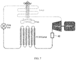
- FIG. 7 is a simplified flow diagram of a micro vapor compression system having in the reversed heat pump mode according to the present invention(reversing valve not shown);
- FIG. 8 is a typical operating cycle of the a micro environmental control system in the heating (heat pump) mode according to the present invention.
- FIG. 9 is an isometric depiction of a typical assembled micro environmental control system with skin removed to reveal internal components.
- FIG. 1 a micro environmental control system ( ⁇ X) that will control the temperature in the near range personal microenvironment (P ⁇ E) of a user.
- the ⁇ X is self-contained, automated, and designed to be installed under a desk, as seen in FIG. 1 , although other configurations of the ⁇ X should be apparent to those of skill in the art.
- system 10 comprises a self-contained micro vapor compression system ( ⁇ VCS) unit 12 having a compressor 14 , a condenser 16 coupled to the compressor 14 and an expansion valve 20 coupled to condenser 16 to form a vapor compression cooling system.
- An evaporator 22 is coupled to expansion valve 24 .
- Unit 12 further includes a thermal storage module 26 having a phase change material (PCM) 28 surrounding evaporator 22 and a fan 30 for selectively directing a stream of air through the phase change material or over the condenser.
- a controller 32 is coupled to compressor 18 and fan 30 for operating system 10 .
- controller 32 may be programmed to operate the system in a cooling mode wherein system 10 is operated to cool phase change material 28 during a first predetermined time period, and fan 30 is operated to direct the stream of room air through air passages 38 passing through phase change material 28 during a second predetermined time period.
- the first predetermined time period is during the night and the second predetermined time period is during the day.
- unit 12 may also include a heater 34 with controller 32 programmed to operate the system in a heating mode where fan 30 directs air over heater 34 .
- a set of dampers 36 may be provided in unit 12 to selectively direct the stream of air through the PCM module 28 , over condenser 16 , or through heater 34 (if part of the system).
- heater 34 may be omitted by programming the controller 32 to operate the ⁇ VCS unit 12 during the day as a heat pump, drawing heat from molten PCM 28 to freeze it, while using fan(s) 30 to blow room air over the condenser 16 and delivering warm air to the occupant, rather than passing the through an already frozen PCM module to deliver cool air to the occupant, as practiced in the cooling mode.
- a reversing valve (not shown) reverses the flow of the refrigerant, allowing the condenser 16 to operate as an evaporator and the evaporator embedded in the PCM module 28 to act as a condenser melting the PCM that has been frozen during daytime ⁇ VCS operation.
- unit 12 may be provided in a micro environmental location, such as under a desk 40 in an office, and operated in a cooling mode by cooling phase change material 28 during a first predetermined time period, such as the nighttime when no one is in the office, and then using fan 34 to direct the stream of air through phase change material 28 during a second predetermined time period, such as the daytime when a user desires cooled air in the office.
- a first predetermined time period such as the nighttime when no one is in the office
- fan 34 to direct the stream of air through phase change material 28 during a second predetermined time period, such as the daytime when a user desires cooled air in the office.
- fan 30 may be operator by controller 32 and used to blow air over heater 34 , over the condenser 16 in the heat pump mode.
- An exemplary ⁇ X will provide less than 100 W of cooling to the P ⁇ E around a seated occupant during the cooling season, or provide up to 100 W of heating to the P ⁇ E in the heating season for up to 10 hours of occupancy in a typical office setting.
- the invention provides efficient comfort to the occupant in an environment that, in order to reduce overall building heating, ventilating and air-conditioning (HVAC) energy consumption, is kept too warm for comfort in the summer season and too cold for comfort in the winter season.
- HVAC overall building heating, ventilating and air-conditioning
- the ⁇ VCS will be operated automatically only during the un-occupied period to freeze a phase-change-material (PCM) in a thermal storage module.
- PCM phase-change-material
- One or more fans move ⁇ 0.4 cfm of air per watt of cooling over the PCM to deliver air at ⁇ 71° F. to the P ⁇ E during occupancy period. Cooled air will be delivered to the P ⁇ E, especially close to the person's upper body and head, through one of several optional air terminal devices (ATD).
- PCM phase-change-material
- Heating may be delivered by a small electric heater integrated into the ⁇ VCS condensing unit and preferably operated only during occupancy periods to supply warm air to the P ⁇ E during the heating season.
- the ⁇ X is self-contained, automated, and designed to be installed under a desk, as seen in FIG. 1 , although other configurations of the ⁇ X should be apparent to those of skill in the art.
- a ⁇ X designed to deliver ⁇ 50 W of cooling during 10 hours of occupancy in the cooling season (500 W-h of total cooling) will consume less than 100 W-h of electricity during the combined night and day freezing and melting cycles.
- the PCM module is preferably sized to provide ⁇ 50 W of cooling over an 10-hour occupancy period.
- inorganic (e.g., salt hydrates) and organic (e.g., paraffins) PCMs with freezing points in the desired 63-66° F. range and with latent heats in excess of 170 kJ/kg are available in bulk or encapsulated form.
- Other PCMs may be investigated, selected and optimized.
- the evaporator tubes of the ⁇ VCS are fully embedded in the PCM as illustrated in FIG. 2 .
- the evaporator saturation temperature in this configuration should be only slightly lower than the freezing point of the PCM, i.e., T e ⁇ 61-63° F. Not only will this help achieve a higher Coefficient of Performance (COP), but embedding the evaporator tubes in the PCM and maintaining the saturated evaporator temperature close to 63° F. will also prevent condensation of indoor moisture on the evaporator coils.
- COP Coefficient of Performance
- refrigerants may be tested for use with the invention, such as those widely used in household refrigerators (e.g., R134a), and other refrigerants such as R245fa and R1233zd, or hydrocarbon refrigerants such as iso-pentane (R601a).
- the condenser of the ⁇ VCS will be cooled by room air at the background temperature of 79° F. Therefore, a condenser saturation temperature of ⁇ 100° F. is reasonable.
- the same fan(s) employed for moving the air through the PCM module during occupied period can also be used for moving the room air over the condenser at night.
- Approximately 20 cfm of air (approximately 0.4 cfm per watt of cooling) flows through the PCM module gaps using a low-power ( ⁇ 1 W) quiet fan.
- the air is drawn from the room at room temperature ( ⁇ 79° F.), cooled by the PCM to about 71° F., and then emerges from the PCM module at a low velocity of ⁇ 1 ft/s.
- Suitable ducting and air terminal devices may be employed to deliver the cooled air to effect near-range control of the P ⁇ E.
- the ⁇ VCS In the cooling mode, the ⁇ VCS will start automatically and run for a few hours (for example, 5 hours) during the un-occupied night-time to freeze the PCM (store cooling in it). In this operating mode, the air blown by the fans will be directed at the condenser of the ⁇ VCS to reject its heat into the unoccupied space; a set of automatic dampers will allow room air to flow over the ⁇ VCS condenser, and another synchronized set of automatic dampers will block room air blown by the fans from entering the PCM module while the ⁇ VCS is operating. The ⁇ VCS will automatically shut down before the person starts work in the morning.
- the system When the person sits at his/her desk, the system will automatically turn on the fans and direct the air to flow through passages in the PCM module, and thereby cool it before delivering it to the P ⁇ E through the ATD.
- the PCM module dampers will be automatically opened and those of the condenser will be automatically closed, thus forcing warm room air to flow through passages inside the PCM module and be cooled by melting the PCM over a 10-hour period.
- the ⁇ VCS may only be operated during un-occupied period to freeze the PCM so that the warm air discharged from the ⁇ VCS will not degrade personal comfort. Further, by operating the ⁇ VCS only during the un-occupied period, compressor and fan noise will not be an issue.
- room air will be blown over the electric heater and delivered to the P ⁇ E during 10 hours of occupancy.
- the PCM dampers will be automatically closed and the condenser/heater dampers will be automatically opened with the fans blowing room air over the heater to heat the air to a more comfortable level.
- the ⁇ X is designed for automatic operation, the occupant can override the ⁇ X automation and operate the system to his/her liking.
- the system can also automatically turn on the ⁇ VCS at night to “charge” the PCM, and shut it off in the early morning hours.
- the system can turn on the fan to move the air through the PCM module ( ⁇ VCS is not operational) on a programmed schedule or upon detecting the presence of a person at the desk.
- thermal storage PCM module in the ⁇ X allows us to shift the operation of the ⁇ VCS to the night hours when the building is not occupied. This avoids two of the major drawbacks of installing an active vapor compression cooling device very close to the occupant: 1) hot exhaust from the condenser of the vapor compression system will not be discharged into the occupied space during occupancy, thus avoiding further thermal discomfort, and 2) distracting compressor noise is avoided during occupancy. Further, some utilities that employ time-of-day electricity pricing, may offer lower electric rates at night.
- ⁇ X can be used in combination with a diverse assortment of personal air delivery systems that traditionally rely on the availability of conditioned air from an underfloor plenum or through unsightly ducts descending from the much more-ubiquitous ceiling supply of conditioned air. Therefore ng them from dependence on underfloor air distribution.
- the ⁇ X of the invention does not suffer from the shortcomings of other State of the Art (SoA) near-range systems and the ⁇ X can deliver the desired adjustments in the P ⁇ E quietly and with minimal use of energy.
- SoA State of the Art
- the PCM is selected from commercially available PCMs that melt and freeze between 60° F. and 66° F., such as paraffin waxes, which melt and freeze at ⁇ 64° F.
- FIG. 2 displays one possible configuration of the ⁇ VCS evaporator using serpentine micro-channel tubes.
- the evaporator tubes of the ⁇ VCS ( FIG. 2 ) are embedded in the PCM module, as shown in FIG. 3 .
- the PCM is encased in plastic or aluminum casings made in the form of slabs with the evaporator sections embedded in these slabs, and completely surrounded by the PCM, as seen in FIG. 3 .
- the air flows in channels between the encased PCM slabs during the day to be cooled by the frozen PCM, causing it to melt.
- the freezing of the PCM during operation of the ⁇ VCS at night in the cooling mode will progress from the tube into the surrounding PCM, whereas the melting during the day in the cooling mode will progress from the outside inwards toward the
- the saturated evaporator temperature can be raised to a more-efficient ⁇ 60° F., ⁇ 3-4° F. lower than PCM freezing temperature. Not only will this allow for a higher and more efficient SET, but also it avoids the problem of indoor moisture condensation on the evaporator surface and associated condensate management challenges when the indoor dew point is higher than 61° F., as it is likely to be with a 79-80° F. indoor DBT and 60% RH. With the ⁇ VCS operating only at night when the space is not occupied, the condenser heat will be rejected into the 79-80° F.
- a compact micro environmental control system can supply ⁇ 50 W of cooling to the near-range P ⁇ E in the cooling season, and add >60 W of heating to the near-range P ⁇ E in the heating season for up to 10 hours of occupancy in a typical office setting.
- the ⁇ X uses a micro vapor-compression system ( ⁇ VCS) that is operated automatically only during the un-occupied period to freeze a phase-change-material (PCM) in a thermal storage module.
- FIG. 4 depicts a simplified flow diagram of such a system and FIG. 5 shows a typical operating cycle in the cooling season and FIG. 6 shown the associated freezing and melting curves.
- the evaporator of the ⁇ VCS ( FIG. 2 ) is embedded in the PCM module ( FIG.
- One or two small quiet fans move an average of ⁇ 20 cfm of air over the PCM to deliver cool air at an average temperature of ⁇ 71° F. to the P ⁇ E during occupancy period (50 W of cooling) through an air terminal device (ATD).
- >60 W heating is provided very efficiently by operating the ⁇ VCS during occupancy period as a heat pump that withdraws heat from the PCM to freeze it, while delivering warm air that is blown over the ⁇ VCS condenser, rather than by a much less efficient electric heater integrated into the condenser as is the case in the aforementioned EXAMPLE 1.
- the same small fan(s) move the air either over the condenser or through the PCM module, depending on the operating mode.
- the PCM will be melting at night by operating the heat pump in reverse mode as shown in FIG. 7 using a reversing valve 48 .
- a typical operating cycle in the heating mode is shown in FIG. 8 .
- This ⁇ X will be self-contained, automated, quiet, ergonomic, and conforms to OSHA standards. It will be designed to be installed unobtrusively under a desk.
- FIG. 9 an isometric depiction of an overall design for the ⁇ X, in which the PCM module is configured as a number of parallel vertical slabs with an embedded micro-channel evaporator and air flow passages in between. The entire system will fit in a box about the size and shape of a desk-top computer ( ⁇ 1.5 ft 3 ), and will weigh less than 35 lbs.
- the ⁇ VCS In the cooling mode, the ⁇ VCS will start automatically and run for ⁇ 8.5 hours during the un-occupied night-time to freeze the PCM (to store cooling in it) as shown in FIG. 5 .
- the air blown by the fans will be directed at the condenser of the ⁇ VCS to reject its heat into the unoccupied space.
- a set of automatic dampers will allow room air to flow over the ⁇ VCS condenser, and another synchronized set of automatic dampers will block room air blown by the fans from entering the PCM module while the ⁇ VCS is operating to prevent heat transfer from the warm room air to the PCM during freezing.
- the ⁇ VCS will automatically shut down before the person starts work in the morning.
- the system When the person is at his/her desk, the system will automatically turn on the fans and direct the air to flow through passages in the PCM module, and cool it before delivering it to the P ⁇ E through the ATD.
- the PCM module dampers will be automatically opened and those of the condenser will be automatically closed, thus forcing the room air to flow through the PCM module passages and be cooled by melting the PCM over a 10-hour period.
- room air In the heating mode, room air will be blown over the condenser of the operating ⁇ VCS and delivered to the P ⁇ E during 10 hours of occupancy.
- the PCM dampers will be automatically closed and the condenser dampers will be automatically opened with the fans blowing room air over the condenser to heat the air to a more comfortable level.
- the ⁇ X is designed for automatic operation, the occupant can override the ⁇ X automation and operate the system to his/her liking. The controller also allows the system to shut off when the person is not at the desk.
- the ⁇ VCS will start automatically at night and provide ⁇ 60 W of cooling to freeze the PCM over approximately a 8.5-hour period.
- the ⁇ VCS will use ⁇ 12.5 W for ⁇ 8.5 h. This is equivalent to ⁇ 11 W, including fan power, if averaged over the 10 hours of occupancy.
- Higher- or lower-capacity ⁇ VCS may be employed to shorten or lengthen the PCM charging period.
- computational fluid dynamics (CFD) analysis indicates that ⁇ X will make possible the removal of >25 W of total heat from a seated occupant in the cooling season.
- the power consumption will be ⁇ 16.5 W for delivering >60 W of heat during 10 hours of occupancy.
- thermal storage PCM module in the ⁇ X allows us to shift the operation of the ⁇ VCS to the night hours when the office is not occupied. This avoids two of the major drawbacks of installing an active VCS heat pump very close to the occupant: 1) warm exhaust from the condenser of an operating VCS will not be discharged into the occupied space during occupancy, and 2) cold air will not be discharged into the occupied space during occupancy. Further, some electric utilities that employ time-of-day pricing may offer lower rates at night or other peak-shaving incentives.
- each of the slabs of the PCM may have an embedded micro-channel evaporator.
- the PCM slabs are contained in an aluminum or plastic.
- the refrigerant zigzags from end to end through the evaporator passages, then bridges externally from one slab to the next.
- the PCM module of FIG. 3 was designed to allow nearly linear melting over the span of 10 hours
- the PCM module is quite compact and can easily fit under a desk. Because of the slight non-linearity of the melting curve, small adjustments may have to be made to the air flow to ensure uniform delivery of 50 W of cooling over the 10-hour time span.
- the ⁇ VCS in the ⁇ A will operate only during times of no-occupancy (at night) to provide ⁇ 60-65 W of cooling for freezing the PCM in ⁇ 8.5 hours, i.e., to store enough cooling at night for later use at the rate of 50 W during a 10-hour workday.
- the evaporator of the ⁇ VCS will be embedded in the PCM module. Owing to the high heat transfer coefficient of the refrigerant forced convection boiling inside the evaporator passages, the saturated evaporator temperature (SET) can be raised to a more-efficient ⁇ 61° F., i.e., ⁇ 3° F. below the 64° F. PCM freezing temperature.
- the ⁇ VCS may be operated during the day to provide heating (heat rejected from the condenser), while freezing a phase-change material (PCM) in the same manner as ⁇ VCS is operated during the night in the cooling season, as seen in FIG. 4 .
- operation may be reversed using the reversing valve, so that heat will be pumped from the room (at 66° F.) into the PCM-embedded evaporator operated as a condenser to melt the PCM, as seen in FIG. 7 .
- This arrangement provides heating at a much higher COP than the electric heater.
- the compressor must be operated during occupancy periods, extra sound insulation may be used to reduce noise.
- this system will deliver more than 600 W-h of heating over a 10 hour occupancy period while consuming less than 165 W-h of electricity during the combined day and night freezing and melting cycles ( FIG. 8 ).
- HFC Hydro-fluoro-carbon
- ODP ozone depletion potential
- GWP global warming potential
- Hydrocarbons such as iso-butane and iso-pentane have been proposed as zero-ODP, low-GWP refrigerants but their flammability limits their use to small systems such as household refrigerators, which makes them potential candidates for the proposed ⁇ VCS.
- Other refrigerants under development are hydro-fluoro-olefins (HFO).
- low-density, low-pressure refrigerants such as those suitable for centrifugal chillers.
- the challenge in the design of a ⁇ VCS is the small volumetric flow rates, which drive down the size of the compressor and the heat transfer equipment to impractically small dimensions if dense refrigerants are used. Therefore, the present invention focused on low-pressure refrigerants such as R245fa, iso-pentane (R601a) and some of the new low-pressure HFO (e.g., R1233zd).
Landscapes
- Engineering & Computer Science (AREA)
- Physics & Mathematics (AREA)
- Mechanical Engineering (AREA)
- Thermal Sciences (AREA)
- General Engineering & Computer Science (AREA)
- Air Conditioning Control Device (AREA)
Abstract
Description
| TABLE 1 | |||
| Module Geometry | Value | Unit | |
| Number of Slabs | 6 | ||
| Slab thickness | 0.019 | m | |
| PCM thickness | 0.017 | m | |
| Slab width | 0.400 | m | |
| Slab pitch | 0.0348 | m | |
| Slab vertical length | 0.309 | m | |
| Air passage width | 0.0154 | m | |
| Air flow rate | 20.0 | cfm | |
Claims (12)
Priority Applications (1)
| Application Number | Priority Date | Filing Date | Title |
|---|---|---|---|
| US15/507,065 US10782052B2 (en) | 2014-08-26 | 2015-08-26 | Micro environmental control system |
Applications Claiming Priority (4)
| Application Number | Priority Date | Filing Date | Title |
|---|---|---|---|
| US201462042012P | 2014-08-26 | 2014-08-26 | |
| US201462091728P | 2014-12-15 | 2014-12-15 | |
| US15/507,065 US10782052B2 (en) | 2014-08-26 | 2015-08-26 | Micro environmental control system |
| PCT/US2015/046859 WO2016033142A1 (en) | 2014-08-26 | 2015-08-26 | Micro environmental control system |
Publications (2)
| Publication Number | Publication Date |
|---|---|
| US20170276408A1 US20170276408A1 (en) | 2017-09-28 |
| US10782052B2 true US10782052B2 (en) | 2020-09-22 |
Family
ID=55400475
Family Applications (1)
| Application Number | Title | Priority Date | Filing Date |
|---|---|---|---|
| US15/507,065 Active US10782052B2 (en) | 2014-08-26 | 2015-08-26 | Micro environmental control system |
Country Status (4)
| Country | Link |
|---|---|
| US (1) | US10782052B2 (en) |
| EP (1) | EP3186569A4 (en) |
| CA (1) | CA2962291C (en) |
| WO (1) | WO2016033142A1 (en) |
Families Citing this family (7)
| Publication number | Priority date | Publication date | Assignee | Title |
|---|---|---|---|---|
| CA2987273A1 (en) | 2015-06-12 | 2016-12-15 | University Of Maryland, College Park | Comfort units and systems, methods, and devices for use thereof |
| DE102017000237A1 (en) * | 2016-03-16 | 2017-09-21 | Liebherr-Hausgeräte Lienz Gmbh | Refrigerant circuit for a refrigerator and / or freezer |
| ES2737673A1 (en) * | 2018-07-13 | 2020-01-15 | Robert Art En Pedra S L | System for temperature control of at least one energy storage module and associated method (Machine-translation by Google Translate, not legally binding) |
| WO2020106478A1 (en) * | 2018-11-20 | 2020-05-28 | Carrier Corporation | Transportation refrigeration system |
| FR3090081B1 (en) * | 2018-12-13 | 2021-02-26 | Commissariat Energie Atomique | Cold production system comprising a compression machine, an absorption machine and a thermal storage system ensuring their coupling |
| US11492126B2 (en) * | 2019-07-31 | 2022-11-08 | B/E Aerospace, Inc. | Restricted space air chiller |
| CN111121514B (en) * | 2020-01-07 | 2024-04-30 | 南京工业大学 | Movable phase-change heat and cold storage device |
Citations (20)
| Publication number | Priority date | Publication date | Assignee | Title |
|---|---|---|---|---|
| DE1301454B (en) | 1962-03-07 | 1969-08-21 | Eigner Otto | Room cooling unit |
| CA2147203A1 (en) | 1995-04-18 | 1996-10-19 | Herbert Richard Mueller | Multiple function heat pump |
| US5575159A (en) | 1995-06-02 | 1996-11-19 | Dittell; Edward W. | Heat energy transfer system |
| US20020043068A1 (en) | 2000-10-13 | 2002-04-18 | Peter Carr | Personal thermal comfort system using thermal storage |
| US20020125001A1 (en) * | 2000-02-09 | 2002-09-12 | Kelly Kevin W. | Crossflow micro heat exchanger |
| US20030014987A1 (en) * | 1999-09-17 | 2003-01-23 | Robert Levenduski | Thermal storage apparatus and method for air conditioning system |
| US20030029173A1 (en) | 2001-08-07 | 2003-02-13 | Bell Lon E. | Thermoelectric personal environment appliance |
| US20030131623A1 (en) * | 2001-09-05 | 2003-07-17 | Suppes Galen J. | Heat pump using phase change materials |
| US20040244398A1 (en) * | 2000-05-01 | 2004-12-09 | Radermacher Reinhard K. | Device for collecting water from air |
| US20050144968A1 (en) * | 2004-01-02 | 2005-07-07 | Shakespeare Walter J. | MEMS based micro vapor compression refrigeration system for microelectronic and photonic thermal control |
| US20050234597A1 (en) * | 2004-04-15 | 2005-10-20 | York International Corporation | Method and apparatus to prevent low temperature damage using an HVAC control |
| US20090025404A1 (en) * | 2007-07-23 | 2009-01-29 | Hussmann Corporation | Combined receiver and heat exchanger for a secondary refrigerant |
| US20110005245A1 (en) * | 2008-01-30 | 2011-01-13 | Dux Manufacturing Limited | Methods and apparatuses for operating heat pumps in hot water systems |
| US20120037342A1 (en) * | 2009-02-11 | 2012-02-16 | Mathew Holloway | Fluid conditioning arrangements |
| US20120152511A1 (en) * | 2010-12-15 | 2012-06-21 | Sunny General International Co., Ltd. | Lhtes device for electric vehicle, system comprising the same and method for controlling the same |
| US20120160446A1 (en) * | 2006-10-10 | 2012-06-28 | Hdt Tactical Systems, Inc. | Vehicle cabin heating cooling and ventilation system |
| WO2013052468A1 (en) | 2011-10-06 | 2013-04-11 | Carrier Corporation | Humidity control for air conditioning system |
| CN103759472A (en) * | 2014-02-06 | 2014-04-30 | 武汉微冷科技有限公司 | Micro heat exchanger with throttling function |
| US20140130536A1 (en) * | 2012-08-30 | 2014-05-15 | Whirlpool Corporation | Refrigeration appliance with two evaporators in different compartments |
| US20150135743A1 (en) * | 2012-05-03 | 2015-05-21 | Carrier Corporation | Air conditioning system having supercooled phase change material |
Family Cites Families (1)
| Publication number | Priority date | Publication date | Assignee | Title |
|---|---|---|---|---|
| US3744272A (en) * | 1971-12-22 | 1973-07-10 | Us Army | Refrigeration system with heat exchanger employing eutectic |
-
2015
- 2015-08-26 EP EP15836221.0A patent/EP3186569A4/en not_active Ceased
- 2015-08-26 US US15/507,065 patent/US10782052B2/en active Active
- 2015-08-26 WO PCT/US2015/046859 patent/WO2016033142A1/en active Application Filing
- 2015-08-26 CA CA2962291A patent/CA2962291C/en active Active
Patent Citations (23)
| Publication number | Priority date | Publication date | Assignee | Title |
|---|---|---|---|---|
| DE1301454B (en) | 1962-03-07 | 1969-08-21 | Eigner Otto | Room cooling unit |
| CA2147203A1 (en) | 1995-04-18 | 1996-10-19 | Herbert Richard Mueller | Multiple function heat pump |
| US5575159A (en) | 1995-06-02 | 1996-11-19 | Dittell; Edward W. | Heat energy transfer system |
| US20030014987A1 (en) * | 1999-09-17 | 2003-01-23 | Robert Levenduski | Thermal storage apparatus and method for air conditioning system |
| US20020125001A1 (en) * | 2000-02-09 | 2002-09-12 | Kelly Kevin W. | Crossflow micro heat exchanger |
| US20040244398A1 (en) * | 2000-05-01 | 2004-12-09 | Radermacher Reinhard K. | Device for collecting water from air |
| US20020043068A1 (en) | 2000-10-13 | 2002-04-18 | Peter Carr | Personal thermal comfort system using thermal storage |
| US6481213B2 (en) | 2000-10-13 | 2002-11-19 | Instatherm Company | Personal thermal comfort system using thermal storage |
| US7426835B2 (en) | 2001-08-07 | 2008-09-23 | Bsst, Llc | Thermoelectric personal environment appliance |
| US20030029173A1 (en) | 2001-08-07 | 2003-02-13 | Bell Lon E. | Thermoelectric personal environment appliance |
| US20030131623A1 (en) * | 2001-09-05 | 2003-07-17 | Suppes Galen J. | Heat pump using phase change materials |
| US20050144968A1 (en) * | 2004-01-02 | 2005-07-07 | Shakespeare Walter J. | MEMS based micro vapor compression refrigeration system for microelectronic and photonic thermal control |
| US20050234597A1 (en) * | 2004-04-15 | 2005-10-20 | York International Corporation | Method and apparatus to prevent low temperature damage using an HVAC control |
| US20120160446A1 (en) * | 2006-10-10 | 2012-06-28 | Hdt Tactical Systems, Inc. | Vehicle cabin heating cooling and ventilation system |
| US9234683B2 (en) | 2006-10-10 | 2016-01-12 | Hdt Expeditionary Systems, Inc. | Vehicle cabin heating cooling and ventilation system |
| US20090025404A1 (en) * | 2007-07-23 | 2009-01-29 | Hussmann Corporation | Combined receiver and heat exchanger for a secondary refrigerant |
| US20110005245A1 (en) * | 2008-01-30 | 2011-01-13 | Dux Manufacturing Limited | Methods and apparatuses for operating heat pumps in hot water systems |
| US20120037342A1 (en) * | 2009-02-11 | 2012-02-16 | Mathew Holloway | Fluid conditioning arrangements |
| US20120152511A1 (en) * | 2010-12-15 | 2012-06-21 | Sunny General International Co., Ltd. | Lhtes device for electric vehicle, system comprising the same and method for controlling the same |
| WO2013052468A1 (en) | 2011-10-06 | 2013-04-11 | Carrier Corporation | Humidity control for air conditioning system |
| US20150135743A1 (en) * | 2012-05-03 | 2015-05-21 | Carrier Corporation | Air conditioning system having supercooled phase change material |
| US20140130536A1 (en) * | 2012-08-30 | 2014-05-15 | Whirlpool Corporation | Refrigeration appliance with two evaporators in different compartments |
| CN103759472A (en) * | 2014-02-06 | 2014-04-30 | 武汉微冷科技有限公司 | Micro heat exchanger with throttling function |
Non-Patent Citations (2)
| Title |
|---|
| International Search Report Form PCT/ISA/220, International Application No. PCT/US2015/046859, pp. 1-7, dated Nov. 24, 2015. |
| Supplementary European Search Report Form 1503, International Application No. PCT/US15146859, pp. 1-8, dated Aug. 26, 2015. |
Also Published As
| Publication number | Publication date |
|---|---|
| EP3186569A1 (en) | 2017-07-05 |
| CA2962291A1 (en) | 2016-03-03 |
| CA2962291C (en) | 2019-03-05 |
| EP3186569A4 (en) | 2018-03-21 |
| WO2016033142A1 (en) | 2016-03-03 |
| US20170276408A1 (en) | 2017-09-28 |
Similar Documents
| Publication | Publication Date | Title |
|---|---|---|
| US10782052B2 (en) | Micro environmental control system | |
| JP4829147B2 (en) | Air conditioning equipment | |
| TWI328100B (en) | Refrigerating apparatus | |
| US20160018115A1 (en) | Window Refrigerator | |
| Murphy | High-performance VAV systems | |
| US10036580B2 (en) | Multi-stage system for cooling a refrigerant | |
| JP2008039306A (en) | Hot water circulation heating system performing heating by circulating hot water in building | |
| US20110197610A1 (en) | Air Conditioner and Pool Heater Dual System | |
| US10066858B2 (en) | Method of heating a building | |
| CN109959073A (en) | air conditioning system and operation method thereof | |
| JP2007163071A (en) | Heat pump type cooling/heating system | |
| Togashi et al. | Development of variable refrigerant flow heat-pump model for annual-energy simulation | |
| US4076074A (en) | High efficiency natural convection heating and cooling system for home dwellings | |
| US20160033145A1 (en) | Room-to-Room Heat Pump | |
| JP4181362B2 (en) | Optimal start-up controller for air conditioning system | |
| JP2008064444A (en) | Hot water circulation heating system circulating hot water to carry out heating in building | |
| JP6747920B2 (en) | Air conditioning system | |
| Alessio et al. | All-air system and radiant floor for heating and cooling in residential buildings: A simulation-based analysis | |
| WO2020183207A1 (en) | A system and an application for the regulation of temperature in a server room | |
| JP2008241231A (en) | Energy-saving air-conditioning control system | |
| US20240219044A1 (en) | Controlling Indoor Temperature Using Radiating Storage | |
| JP6974553B2 (en) | Air conditioner and air conditioning system for air supply / exhaust path | |
| TWM392331U (en) | Cooling and heating equipment having thermoelectric cooling chip | |
| US20240142116A1 (en) | Heat pump with solar heating and radiative cooling | |
| Morovat et al. | Performance Analysis and Control Strategies to Enhance Free Cooling with an Active PCM-Heat Exchanger |
Legal Events
| Date | Code | Title | Description |
|---|---|---|---|
| AS | Assignment |
Owner name: SYRACUSE UNIVERSITY, NEW YORK Free format text: ASSIGNMENT OF ASSIGNORS INTEREST;ASSIGNOR:KHALIFA, HUSSEIN EZZAT;REEL/FRAME:041385/0467 Effective date: 20170209 |
|
| STPP | Information on status: patent application and granting procedure in general |
Free format text: FINAL REJECTION MAILED |
|
| STPP | Information on status: patent application and granting procedure in general |
Free format text: AWAITING RESPONSE FOR INFORMALITY, FEE DEFICIENCY OR CRF ACTION |
|
| STPP | Information on status: patent application and granting procedure in general |
Free format text: DOCKETED NEW CASE - READY FOR EXAMINATION |
|
| STPP | Information on status: patent application and granting procedure in general |
Free format text: NON FINAL ACTION MAILED |
|
| STPP | Information on status: patent application and granting procedure in general |
Free format text: RESPONSE TO NON-FINAL OFFICE ACTION ENTERED AND FORWARDED TO EXAMINER |
|
| STPP | Information on status: patent application and granting procedure in general |
Free format text: EX PARTE QUAYLE ACTION MAILED |
|
| AS | Assignment |
Owner name: CONMED CORPORATION, NEW YORK Free format text: ASSIGNMENT OF ASSIGNORS INTEREST;ASSIGNORS:KOLTZ, MICHAEL L, JR.;EILERS, DEREK;REEL/FRAME:052441/0385 Effective date: 20200420 |
|
| STPP | Information on status: patent application and granting procedure in general |
Free format text: RESPONSE TO EX PARTE QUAYLE ACTION ENTERED AND FORWARDED TO EXAMINER |
|
| STPP | Information on status: patent application and granting procedure in general |
Free format text: NOTICE OF ALLOWANCE MAILED -- APPLICATION RECEIVED IN OFFICE OF PUBLICATIONS |
|
| FEPP | Fee payment procedure |
Free format text: ENTITY STATUS SET TO MICRO (ORIGINAL EVENT CODE: MICR); ENTITY STATUS OF PATENT OWNER: MICROENTITY |
|
| STCF | Information on status: patent grant |
Free format text: PATENTED CASE |
|
| AS | Assignment |
Owner name: U.S. DEPARTMENT OF ENERGY, DISTRICT OF COLUMBIA Free format text: CONFIRMATORY LICENSE;ASSIGNOR:SUSYRACUSE UNIVERSITY;REEL/FRAME:064530/0785 Effective date: 20180426 |
|
| MAFP | Maintenance fee payment |
Free format text: PAYMENT OF MAINTENANCE FEE, 4TH YEAR, MICRO ENTITY (ORIGINAL EVENT CODE: M3551); ENTITY STATUS OF PATENT OWNER: MICROENTITY Year of fee payment: 4 |