US10746292B2 - Actuator device for a gearbox of a motor vehicle and corresponding gearbox for a motor vehicle - Google Patents
Actuator device for a gearbox of a motor vehicle and corresponding gearbox for a motor vehicle Download PDFInfo
- Publication number
- US10746292B2 US10746292B2 US14/778,853 US201414778853A US10746292B2 US 10746292 B2 US10746292 B2 US 10746292B2 US 201414778853 A US201414778853 A US 201414778853A US 10746292 B2 US10746292 B2 US 10746292B2
- Authority
- US
- United States
- Prior art keywords
- selector
- shafts
- shaft
- actuator device
- selector shafts
- Prior art date
- Legal status (The legal status is an assumption and is not a legal conclusion. Google has not performed a legal analysis and makes no representation as to the accuracy of the status listed.)
- Active
Links
- 230000005540 biological transmission Effects 0.000 claims description 42
- 230000007935 neutral effect Effects 0.000 claims description 9
- 238000006073 displacement reaction Methods 0.000 description 14
- 230000009977 dual effect Effects 0.000 description 6
- 238000010276 construction Methods 0.000 description 1
- 230000008878 coupling Effects 0.000 description 1
- 238000010168 coupling process Methods 0.000 description 1
- 238000005859 coupling reaction Methods 0.000 description 1
- 230000000717 retained effect Effects 0.000 description 1
Images


Classifications
-
- F—MECHANICAL ENGINEERING; LIGHTING; HEATING; WEAPONS; BLASTING
- F16—ENGINEERING ELEMENTS AND UNITS; GENERAL MEASURES FOR PRODUCING AND MAINTAINING EFFECTIVE FUNCTIONING OF MACHINES OR INSTALLATIONS; THERMAL INSULATION IN GENERAL
- F16H—GEARING
- F16H61/00—Control functions within control units of change-speed- or reversing-gearings for conveying rotary motion ; Control of exclusively fluid gearing, friction gearing, gearings with endless flexible members or other particular types of gearing
- F16H61/26—Generation or transmission of movements for final actuating mechanisms
- F16H61/28—Generation or transmission of movements for final actuating mechanisms with at least one movement of the final actuating mechanism being caused by a non-mechanical force, e.g. power-assisted
- F16H61/32—Electric motors actuators or related electrical control means therefor
-
- F—MECHANICAL ENGINEERING; LIGHTING; HEATING; WEAPONS; BLASTING
- F16—ENGINEERING ELEMENTS AND UNITS; GENERAL MEASURES FOR PRODUCING AND MAINTAINING EFFECTIVE FUNCTIONING OF MACHINES OR INSTALLATIONS; THERMAL INSULATION IN GENERAL
- F16H—GEARING
- F16H63/00—Control outputs from the control unit to change-speed- or reversing-gearings for conveying rotary motion or to other devices than the final output mechanism
- F16H63/02—Final output mechanisms therefor; Actuating means for the final output mechanisms
- F16H63/08—Multiple final output mechanisms being moved by a single common final actuating mechanism
- F16H63/20—Multiple final output mechanisms being moved by a single common final actuating mechanism with preselection and subsequent movement of each final output mechanism by movement of the final actuating mechanism in two different ways, e.g. guided by a shift gate
- F16H63/206—Multiple final output mechanisms being moved by a single common final actuating mechanism with preselection and subsequent movement of each final output mechanism by movement of the final actuating mechanism in two different ways, e.g. guided by a shift gate the final output mechanisms being mounted coaxially on a single shaft, e.g. mono rail shift mechanism
-
- F—MECHANICAL ENGINEERING; LIGHTING; HEATING; WEAPONS; BLASTING
- F16—ENGINEERING ELEMENTS AND UNITS; GENERAL MEASURES FOR PRODUCING AND MAINTAINING EFFECTIVE FUNCTIONING OF MACHINES OR INSTALLATIONS; THERMAL INSULATION IN GENERAL
- F16H—GEARING
- F16H63/00—Control outputs from the control unit to change-speed- or reversing-gearings for conveying rotary motion or to other devices than the final output mechanism
- F16H63/02—Final output mechanisms therefor; Actuating means for the final output mechanisms
- F16H63/08—Multiple final output mechanisms being moved by a single common final actuating mechanism
- F16H63/20—Multiple final output mechanisms being moved by a single common final actuating mechanism with preselection and subsequent movement of each final output mechanism by movement of the final actuating mechanism in two different ways, e.g. guided by a shift gate
- F16H63/22—Multiple final output mechanisms being moved by a single common final actuating mechanism with preselection and subsequent movement of each final output mechanism by movement of the final actuating mechanism in two different ways, e.g. guided by a shift gate the final output mechanisms being simultaneously moved by the final actuating mechanism
-
- F—MECHANICAL ENGINEERING; LIGHTING; HEATING; WEAPONS; BLASTING
- F16—ENGINEERING ELEMENTS AND UNITS; GENERAL MEASURES FOR PRODUCING AND MAINTAINING EFFECTIVE FUNCTIONING OF MACHINES OR INSTALLATIONS; THERMAL INSULATION IN GENERAL
- F16H—GEARING
- F16H63/00—Control outputs from the control unit to change-speed- or reversing-gearings for conveying rotary motion or to other devices than the final output mechanism
- F16H63/02—Final output mechanisms therefor; Actuating means for the final output mechanisms
- F16H63/28—Final output mechanisms therefor; Actuating means for the final output mechanisms two or more final actuating mechanisms moving the same final output mechanism
-
- F—MECHANICAL ENGINEERING; LIGHTING; HEATING; WEAPONS; BLASTING
- F16—ENGINEERING ELEMENTS AND UNITS; GENERAL MEASURES FOR PRODUCING AND MAINTAINING EFFECTIVE FUNCTIONING OF MACHINES OR INSTALLATIONS; THERMAL INSULATION IN GENERAL
- F16H—GEARING
- F16H63/00—Control outputs from the control unit to change-speed- or reversing-gearings for conveying rotary motion or to other devices than the final output mechanism
- F16H63/02—Final output mechanisms therefor; Actuating means for the final output mechanisms
- F16H63/30—Constructional features of the final output mechanisms
- F16H63/3069—Interrelationship between two or more final output mechanisms
-
- F—MECHANICAL ENGINEERING; LIGHTING; HEATING; WEAPONS; BLASTING
- F16—ENGINEERING ELEMENTS AND UNITS; GENERAL MEASURES FOR PRODUCING AND MAINTAINING EFFECTIVE FUNCTIONING OF MACHINES OR INSTALLATIONS; THERMAL INSULATION IN GENERAL
- F16H—GEARING
- F16H61/00—Control functions within control units of change-speed- or reversing-gearings for conveying rotary motion ; Control of exclusively fluid gearing, friction gearing, gearings with endless flexible members or other particular types of gearing
- F16H61/26—Generation or transmission of movements for final actuating mechanisms
- F16H61/28—Generation or transmission of movements for final actuating mechanisms with at least one movement of the final actuating mechanism being caused by a non-mechanical force, e.g. power-assisted
- F16H2061/2853—Electromagnetic solenoids
-
- F—MECHANICAL ENGINEERING; LIGHTING; HEATING; WEAPONS; BLASTING
- F16—ENGINEERING ELEMENTS AND UNITS; GENERAL MEASURES FOR PRODUCING AND MAINTAINING EFFECTIVE FUNCTIONING OF MACHINES OR INSTALLATIONS; THERMAL INSULATION IN GENERAL
- F16H—GEARING
- F16H63/00—Control outputs from the control unit to change-speed- or reversing-gearings for conveying rotary motion or to other devices than the final output mechanism
- F16H63/02—Final output mechanisms therefor; Actuating means for the final output mechanisms
- F16H2063/025—Final output mechanisms for double clutch transmissions
-
- F—MECHANICAL ENGINEERING; LIGHTING; HEATING; WEAPONS; BLASTING
- F16—ENGINEERING ELEMENTS AND UNITS; GENERAL MEASURES FOR PRODUCING AND MAINTAINING EFFECTIVE FUNCTIONING OF MACHINES OR INSTALLATIONS; THERMAL INSULATION IN GENERAL
- F16H—GEARING
- F16H63/00—Control outputs from the control unit to change-speed- or reversing-gearings for conveying rotary motion or to other devices than the final output mechanism
- F16H63/02—Final output mechanisms therefor; Actuating means for the final output mechanisms
- F16H63/08—Multiple final output mechanisms being moved by a single common final actuating mechanism
- F16H63/20—Multiple final output mechanisms being moved by a single common final actuating mechanism with preselection and subsequent movement of each final output mechanism by movement of the final actuating mechanism in two different ways, e.g. guided by a shift gate
- F16H2063/208—Multiple final output mechanisms being moved by a single common final actuating mechanism with preselection and subsequent movement of each final output mechanism by movement of the final actuating mechanism in two different ways, e.g. guided by a shift gate using two or more selecting fingers
-
- F—MECHANICAL ENGINEERING; LIGHTING; HEATING; WEAPONS; BLASTING
- F16—ENGINEERING ELEMENTS AND UNITS; GENERAL MEASURES FOR PRODUCING AND MAINTAINING EFFECTIVE FUNCTIONING OF MACHINES OR INSTALLATIONS; THERMAL INSULATION IN GENERAL
- F16H—GEARING
- F16H63/00—Control outputs from the control unit to change-speed- or reversing-gearings for conveying rotary motion or to other devices than the final output mechanism
- F16H63/02—Final output mechanisms therefor; Actuating means for the final output mechanisms
- F16H63/30—Constructional features of the final output mechanisms
- F16H63/304—Constructional features of the final output mechanisms the final output mechanisms comprising elements moved by electrical or magnetic force
- F16H2063/305—Constructional features of the final output mechanisms the final output mechanisms comprising elements moved by electrical or magnetic force using electromagnetic solenoids
-
- F—MECHANICAL ENGINEERING; LIGHTING; HEATING; WEAPONS; BLASTING
- F16—ENGINEERING ELEMENTS AND UNITS; GENERAL MEASURES FOR PRODUCING AND MAINTAINING EFFECTIVE FUNCTIONING OF MACHINES OR INSTALLATIONS; THERMAL INSULATION IN GENERAL
- F16H—GEARING
- F16H63/00—Control outputs from the control unit to change-speed- or reversing-gearings for conveying rotary motion or to other devices than the final output mechanism
- F16H63/02—Final output mechanisms therefor; Actuating means for the final output mechanisms
- F16H63/30—Constructional features of the final output mechanisms
- F16H63/3069—Interrelationship between two or more final output mechanisms
- F16H2063/3073—Interrelationship between two or more final output mechanisms final output mechanisms mounted on a single shaft
Definitions
- the invention relates to an actuator device for a transmission of a motor vehicle with multiple selector shafts which are each displaceable in a first direction between multiple selection positions and in a second direction between multiple shifting positions, and which each have a connecting element which in at least one of the selection positions is operatively connected with at least one selector rail of the transmission for transmitting a movement of the selector shaft in the second direction to the selector rail.
- the invention also relates to a corresponding transmission of a motor vehicle.
- the transmission includes the at least one selector rail, however, preferably multiple selector rails.
- Each selector rail is for example operatively connected with a selector sleeve and/or a synchronizer ring of the transmission.
- This arrangement is configured so that by the displacement of the selector rail into a defined position a defined gear of the transmission is selected and set or engaged.
- each selector rail can be brought into multiple positions, wherein a first one of the positions is a free wheeling position, in which by means of this selector rail no gear but rater a neutral position is set in the transmission.
- a defined gear is correspondingly selected and engaged in the transmission.
- the positions can include a third position in which another gear is selected and engaged in the transmission.
- each selector rail can be brought into three positions, wherein these positions correspond to a neutral position, a first one of multiple gears of the transmission or a second one of the gears.
- any desired number of such selector rails can be provided so that by corresponding arrangement of the selector rails a defined gear can be selected from a plurality of different gears and engaged in the transmission.
- the actuator device is provided, which is assigned to the transmission of the motor vehicle.
- the actuator device includes the multiple selector shafts.
- Each of the selector shafts can be operatively connected with at least one of the selector rails of the transmission via the respective connecting element.
- Each selector shaft is hereby assigned at least one of the selector rails.
- an assignment of multiple different selector rails to at least one of the selector shafts, in particular to each selector shaft can be provided.
- the selector shafts can each be displaced in a first direction between multiple selection positions and in a second direction between multiple shifting positions. As a result of the displacement of the respective selector shaft into a defined one of the selection positions it is determined whether and with what selector rail this selector shaft becomes operatively connected.
- the selector rail selected by the selection position is displaced so that according to the explanations above a defined gear is selected and engaged in the transmission.
- an actuator device for a transmission of a motor vehicle including a plurality of selector shafts displaceable into a first direction between multiple selection positions and in a second direction between multiple shifting positions, each said selector shafts having a connecting element, which in at least one of the selection positions is operatively connected with at least one selector rail of the transmission for transmitting a movement of the selector shaft in the second direction to the selector rail, wherein the selector shafts are mounted relative to each other so as to be movable relative to each other in the first direction and to be fixed relative to each other in the second direction; a plurality of first setting devices, wherein the selection positions of the selector shafts are settable independent of each other by the first setting devices, and a second setting device, wherein the selector shafts are displaceable together between the shifting positions by the second setting device.
- the selector shafts are mounted relative to each other so as to be movable relative to each other in the first direction and so as to be fixed relative to each other in the second direction, wherein the selection positions of the selector shafts can be adjusted independent of each other with multiple first setting devices, and wherein the selector shafts can be displaced together between the shifting positions by means of a second setting device.
- each selector shaft is assigned an own first setting device. In this way each selector shaft can be displaced into the desired selection position independent of the other selector shafts. The selection position of each selector shaft can thus be selected and set entirely independent of the selection positions of the other selector shaft.
- all selector shafts are assigned a common second setting device.
- the actuator device thus has multiple first setting devices but only one single second setting device.
- the single setting device serves for displacing all selector shafts together between the shifting positions, so that all selector shafts are always present in the same shifting position that is selected from the available shifting positions.
- the actuator device according to the invention does not require a plurality of second setting devices.
- the actuator device according to the invention it is possible to select and set multiple gears simultaneously, which is in particular very important with regard to designing the transmission as dual clutch transmission.
- multiple sub-transmissions in particular two sub-transmissions, are provided.
- Each of these sub-transmissions are assigned at least one selector shaft of the actuator device and with this an own first setting device.
- only one single second setting device is available to the dual clutch transmission so that all selector shafts of the dual clutch transmission can be or are displaced together between the multiple shifting positions.
- selector shafts can be provided, wherein preferably at least two, at least three or at least four selector shafts are present.
- the selector shafts are arranged relative to each other so that they can be freely moved relative to each other in a first direction at least within defined limits. In the second direction on the other hand they are fixed relative to each other so that in the case of a displacement of one of the selector shafts between different shifting positions always all of the selector shafts are displaced in the selected shifting position.
- each selector shaft is only assigned one or at least two selector rails.
- the number of the selector rails that are assigned to each selector shaft is in particular determined by way of the total number of the gears of the transmission and the number of the selector shafts. For example when four selector rails and two selector shafts are present, each of the selector shafts have to be assigned at least two of the selector rails. On the other hand, when more selector shafts, for example four selector shafts, are provided each of the selector shaft can only be assigned one single selector rail. Nevertheless all gears of the transmission can be controlled by means of the actuator device device.
- a refinement of the invention provides that the selector shafts are supported for rotation about a common rotation axis.
- the selector shafts are thus arranged coaxial to each other.
- a shaft-hub-connection is provided between the selector shafts or between an intermediate shaft and at least one of the selector shafts, in particular thus a formfitting connection, which permits a displacement of the selector shafts in the direction of the common rotation axis, but on the other hand transmits a rotation movement about the rotation axis between all selector shafts.
- the shaft-hub-connection is configured as gear coupling.
- each selector shaft has a restoring device, which urges the selector shaft in the direct of a selection position which represents a neutral position.
- the neutral position is that one of the multiple selection positions in which the selector shaft is not operatively connected to the selector shaft or selector shafts assigned to it.
- a particularly advantageous embodiment of the invention provides that the first direction is the axial direction relative to the rotation axis and/or the second direction is the circumferential direction relative to the rotation axis.
- the first direction is the circumferential direction relative to the rotation axis and/or the second direction is the circumferential direction relative to the rotation axis.
- the first setting devices are configured as magnetic setting devices.
- the displacement of the selector shafts into the respectively desired selection position thus occurs by means of the magnetic setting devices which for this purpose have at least one magnetic coil which is configured to cause a displacement of the respective selector shaft in the first direction when supplied with current.
- the use of such magnetic setting devices has the advantage that extremely short setting times can be achieved.
- the second setting device is configured as electric motor, which is operatively connected to the selector shafts.
- the electric motor is provided for generating a rotational movement and to transmit this rotational movement to the selector shafts.
- the electric motor is directly, or via a transmission, operatively connected with one of the selector shafts or an intermediate shaft.
- the selector shafts are operatively connected with the second setting device via an intermediate shaft.
- the electric motor is for example directly connected to the intermediate shaft, or via the transmission.
- Connected to the intermediate shaft is at least one of the selector shafts so that the torque of the electric motor can be transmitted between the intermediate shaft and the at least one selector shaft.
- the selector shafts are supported on the intermediate shaft in rotative fixed relationship with the intermediate shaft and so as to be axially displaceable.
- This is in particular the case when exactly two selector shafts are provided, which are for example connected to the intermediate shaft at opposing sides of the intermediate shaft.
- one of the shaft-hub-connections as described above is realized between each of the selector shafts and the intermediate shaft.
- the rotational movement is thus transmitted to the selector shafts that are connected to the intermediate shaft so that by means of the second setting device these selector shafts can be displaced together between the multiple shifting positions.
- the invention also relates to a transmission of a motor vehicle with an actuator device device, in particular according to the description above, wherein the actuator device has multiple selector shafts, which can be displaced in a first direction between multiple selection positions and in a second direction between multiple shifting positions, and which each have a connecting element which in at least one of the selection positions is operatively connected with at least one selector rail of the transmission for transmitting a movement of the selector shaft in the second direction to the selector rail.
- the selector shafts are mounted relative to each other so that they are movable relative to each other in the first direction and are fixed relative to each other in the second direction, wherein the selection positions of the selector shafts can be set independent of each other by means of multiple first setting devices, and wherein the selector shafts can be displaced together between the shifting positions by means of a second setting device.
- the advantages of such a configuration of the actuator device and the transmission have already been mentioned above.
- the actuator device and also the transmission can be further refined according to the description above, so that reference is made to this description.
- the transmission is for example constructed as multiple clutch transmission, in particular as dual clutch transmission.
- FIG. 1 a schematic representation of a first embodiment of an actuator device for a transmission of a motor vehicle
- FIG. 2 a schematic representation of a second embodiment of the actuator device device
- FIG. 3 a schematic representation of a first variant of the first embodiment
- FIG. 4 a schematic representation of a second variant of the first embodiment
- FIG. 5 a schematic representation of a third variant of the first embodiment
- FIG. 6 a schematic representation of a fourth variant of the first embodiment
- FIG. 7 A further schematic representation of the first variant of the first embodiment
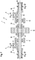
- FIG. 8 a schematic representation of a third embodiment of the actuator device in a first view
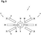
- FIG. 9 a schematic representation of the third embodiment of the X-rated advice in its second view.
- FIG. 1 shows a schematic representation of an actuator device 1 as part of a transmission 2 of a motor vehicle.
- the transmission is constructed in particular as dual clutch transmission with two sub-transmissions 3 and 4 , wherein selector rails 5 and 6 are assigned to the first sub-transmission 3 , and selector rails 7 and 8 are assigned to the second sub-transmission 4 .
- Each of the selector rails 5 to 8 can be displaced into at least two positions, however in particular more than two positions. For example a of displacement each of the selector rails 5 to 8 in a first position situated behind the drawing plane, a second position situated in the Trenton plane, and a third position situated above the drawing plane is provided.
- he defined either of these sub transmission 3 or 4 is respectively selected and engaged in the first and the third position, while the second position represents a neutral position, in which no gear is engaged by means of the respective selector rail 5 , 6 , 7 or 8 .
- each sub-transmission 3 and 4 is assigned a selector shaft 9 or 10 .
- Each of the selector shafts 9 and 10 can be displaced in a first direction between multiple selection positions, for which each selector shaft 9 and 10 is respectively assigned a first setting device 11 or 12 .
- each of the selector shafts 9 and 10 can be displaced into three different selection positions.
- the selection positions of the selector shaft 9 are indicated by the arrows 13 , 14 and 15 , wherein the selection positions of the selector shaft 10 are indicated by the arrows 16 , 17 and 18 .
- the selector shaft 9 is operatively connected with the selector rail 5 via a here not shown connecting element, while the same is true in the selection position 15 with regard to the selector rail 6 .
- an operative connection with the selector rail 7 is present in the selection position 16
- an operative connection with the selector rail 8 is present in the selection position 18 .
- each of the selector shafts 9 and 10 can be displaced between multiple shifting positions, they are however always displaced together by means of a second setting device 19 .
- the selector shafts 9 and 10 are mounted relative to each other so that they are movable relative to each other in the first direction and are fixed relative to each other in the second direction.
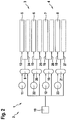
- FIG. 2 shows a second embodiment of the actuator device 1 .
- each of the sub-transmission 3 and 4 are not only assigned a single selector shaft 9 or 10 but rather respectively two selector shafts 9 and 20 or 10 and 21 .
- each of the selector shafts 9 , 10 , 20 and 21 is assigned a respective setting device 11 , 12 , 22 or 23 so that each of the selector shafts 9 , 10 , 20 and 21 can be brought into the desired selection position independent of the respective other selector shafts.
- each of the selector shafts 9 , 10 , 20 and 21 is assigned only one of the selector rails 5 , 6 , 7 and 8 .
- each of the selector shafts 10 , 20 and 21 can be brought into a selection position 13 , 15 , 16 and 18 in which it is operatively connected with the respective selector rail 5 , 6 , 7 or 8 .
- no operative connection is present in a different selection position indicated by the arrows 24 , 25 , 26 and 27 on the other hand no operative connection is present.
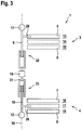
- FIG. 3 shows a first variant of the first embodiment of the actuator device 1 .
- a connecting element 28 or 29 is provided on each of the selector shafts 9 and 10 for generating the respective operative connection with the selector rail 5 or 6 or the selector rail 7 or 8 .
- the different selection positions are indicated by reference numerals 13 to 18 .
- the selector shafts 9 and 10 can be rotated about a common rotation axis.
- the first direction, which serves for setting the desired selection position is thus the axial direction relative to the rotation axis 30
- the second direction which serves for setting the shifting position
- the first setting devices 11 and 12 are constructed as magnetic setting devices, which enables an axial displacement of the respective selector shaft 9 or 10 .
- the second setting device 19 on the other hand is constructed as an electric motor, which is operatively connected with the two selector shafts 9 and 10 via an intermediate shaft 31 .
- the intermediate shaft 31 is supported so as to be only rotatable about the rotation axis 30 , i.e., it cannot be displaced in axial direction.
- shaft-hub-connections 32 or 33 are provided between the intermediate shaft 31 and the selector shafts 9 and 10 . Via these shaft-hub-connections 32 and 33 the selector shafts 9 to 10 are supported on the intermediate shaft 31 in rotative fixed relationship with the intermediate shat 31 and so as to be displaceable in axial direction.
- FIG. 4 shows a second variant of the first embodiment of the actuator device 1 . While in the first variant the selector shafts 9 and 10 are arranged on opposite sides of the intermediate shaft 31 , in this case they are arranged on the same side. Hereby the selector shafts 9 and 10 are arranged coaxial relative to each other, wherein however the selector shaft 9 traverses the selector shaft 10 .
- the selector shaft 10 is insofar constructed as a hollow shaft.
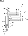
- FIG. 5 shows a third variant of the first embodiment.
- the selector shaft 10 is constructed as a hollow shaft in such a manner that also the intermediate shaft 31 is partially received in the selector shaft 10 .
- the shaft-hub-connection 33 between an outside of the intermediate shaft 31 and an inner wall of the selector shaft 10 is realized.
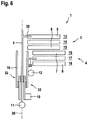
- FIG. 6 shows a fourth variant the first embodiment of the actuator device 1 . Also in this case reference is made to the description above. The difference to the third variant is essentially that the selector shaft 9 in this case fully traverses the intermediate shaft 31 in axial direction, so that correspondingly the second setting device 19 has to be arranged in an alternative position. This enables an arrangement, which is particularly space-saving in axial direction.
- FIG. 7 shows a schematic representation of the first variant of the first embodiment, so that insofar references is made to the description above.
- each selector shaft 9 and 10 is assigned a respective restoring device 34 or 35 .
- Each of the restoring devices 34 and 35 essentially consist of at least one spring element 36 and a positionally fixed reference element 37 .
- two spring elements 36 and 36 ′ are provided, which can exert opposing spring forces onto the respective selector shaft 9 or 10 .
- the restoring devices 34 and 35 serve for urging the respective selector shaft 9 or 10 into the selection position, i.e., a neutral position, in which no operative connection to the selector rails 5 and 6 or 7 and 8 is generated via the connecting element 28 or 29 .
- FIG. 8 shows a schematic representation of a third embodiment of the actuator device in a top view so that the rotation axis 30 is situated in the drawing plane.
- the first direction is the circumferential direction relative to the rotation axis and the second direction is the axial direction relative to the rotation axis.
- rotation of the respective selector shaft 9 or 10 can be effected by means of the first setting devices 11 and 12 .
- the second setting device 19 on the other hand serves for displacing the selector shafts 9 and 10 together in axial direction.
- FIG. 9 shows a further view of the third embodiment, in a side view or sectional side view, in which the rotation axis 30 is perpendicular to the drawing plane.
Landscapes
- Engineering & Computer Science (AREA)
- General Engineering & Computer Science (AREA)
- Mechanical Engineering (AREA)
- Gear-Shifting Mechanisms (AREA)
- Structure Of Transmissions (AREA)
Applications Claiming Priority (4)
| Application Number | Priority Date | Filing Date | Title |
|---|---|---|---|
| DE102013004953.9 | 2013-03-22 | ||
| DE102013004953 | 2013-03-22 | ||
| DE102013004953.9A DE102013004953A1 (de) | 2013-03-22 | 2013-03-22 | Aktuatoreinrichtung für ein Getriebe eines Kraftfahrzeugs sowie entsprechendes Getriebe eines Kraftfahrzeugs |
| PCT/EP2014/000700 WO2014146771A1 (de) | 2013-03-22 | 2014-03-14 | Aktuatoreinrichtung für ein getriebe eines kraftfahrzeugs sowie entsprechendes getriebe eines kraftfahrzeugs |
Publications (2)
| Publication Number | Publication Date |
|---|---|
| US20160047468A1 US20160047468A1 (en) | 2016-02-18 |
| US10746292B2 true US10746292B2 (en) | 2020-08-18 |
Family
ID=50349570
Family Applications (1)
| Application Number | Title | Priority Date | Filing Date |
|---|---|---|---|
| US14/778,853 Active US10746292B2 (en) | 2013-03-22 | 2014-03-14 | Actuator device for a gearbox of a motor vehicle and corresponding gearbox for a motor vehicle |
Country Status (5)
| Country | Link |
|---|---|
| US (1) | US10746292B2 (zh) |
| EP (1) | EP2976555B1 (zh) |
| CN (1) | CN105051427B (zh) |
| DE (1) | DE102013004953A1 (zh) |
| WO (1) | WO2014146771A1 (zh) |
Families Citing this family (6)
| Publication number | Priority date | Publication date | Assignee | Title |
|---|---|---|---|---|
| KR101833627B1 (ko) * | 2016-07-18 | 2018-04-13 | 현대다이모스(주) | 더블 클러치 변속기의 기어 액추에이터 |
| DE102016213805A1 (de) * | 2016-07-27 | 2018-02-01 | Zf Friedrichshafen Ag | Getriebeaktuator, Getriebe sowie Kraftfahrzeug |
| DE102016009694A1 (de) * | 2016-08-11 | 2018-02-15 | Volkswagen Aktiengesellschaft | Verfahren zur Steuerung und/oder Regelung eines Antriebsmotors bzw. Antriebssystem arbeitend nach dem zuvor genannten Verfahren |
| EP3626571B1 (en) | 2018-09-18 | 2022-08-17 | KNORR-BREMSE Systeme für Nutzfahrzeuge GmbH | Control architecture for a vehicle |
| DE102019200498A1 (de) * | 2019-01-16 | 2020-07-16 | Knorr-Bremse Systeme für Nutzfahrzeuge GmbH | Aktuatoreinheit |
| WO2021146916A1 (en) * | 2020-01-21 | 2021-07-29 | Knorr-Bremse Braking Systems For Commercial Vehicles (Dalian) Co., Ltd. | Shifting device for a transmission |
Citations (19)
| Publication number | Priority date | Publication date | Assignee | Title |
|---|---|---|---|---|
| DE4007120A1 (de) | 1989-03-22 | 1990-09-27 | Volkswagen Ag | Zahnrad-wechselgetriebe |
| DE10205689C1 (de) | 2002-02-05 | 2003-07-10 | Getrag Getriebe Zahnrad | Schaltvorrichtung für ein Stirnradgetriebe |
| DE10249951A1 (de) | 2002-10-26 | 2004-05-19 | Daimlerchrysler Ag | Verfahren zur Steuerung eines Antriebsstrangs |
| WO2004081418A1 (de) | 2003-03-14 | 2004-09-23 | Volkswagen Aktiengesellschaft | Getriebe bzw. verfahren zur steuerung eines getriebes für ein kraftfahrzeug |
| DE102004052804B3 (de) | 2004-10-26 | 2006-01-19 | Getrag Getriebe-Und Zahnradfabrik Hermann Hagenmeyer Gmbh & Cie Kg | Schalteinrichtung |
| US20060201269A1 (en) | 2003-01-24 | 2006-09-14 | Maillard Jean P | Internal control device for mechanical gearbox |
| DE102005058406A1 (de) | 2005-12-07 | 2007-06-14 | Dr.Ing.H.C. F. Porsche Ag | Betätigungseinrichtung für ein Schaltgetriebe |
| US7240578B2 (en) * | 2004-06-15 | 2007-07-10 | Aisin Ai Co., Ltd. | Gearing and power transmission apparatus |
| DE102007010871A1 (de) | 2006-04-07 | 2007-10-11 | Ford Global Technologies, LLC, Dearborn | Betätigungsmechanismus für Schaltmotoren eines Getriebes |
| DE602004006681T2 (de) | 2003-08-29 | 2008-01-24 | Peugeot Citroën Automobiles S.A. | Interne Steuereinrichtung für Schaltgetriebe |
| WO2009065571A1 (de) | 2007-11-20 | 2009-05-28 | Magna Powertrain Ag & Co Kg | Betätigungseinheit für ein klauengetriebe und klauengetriebe mit einer solchen betätigungseinheit |
| EP2143979A1 (en) | 2008-05-13 | 2010-01-13 | MAGNETI MARELLI POWERTRAIN S.p.A. | Double-clutch gearchange |
| DE102009056147A1 (de) | 2008-11-27 | 2010-06-17 | Mitsubishi Jidosha Kogyo K.K. | Schaltbetätigungsvorrichtung eines Automatikgetriebes |
| DE102010050382A1 (de) | 2009-11-09 | 2011-06-30 | GM Global Technology Operations LLC, ( n. d. Ges. d. Staates Delaware ), Mich. | Betätigungssystem für eine elektromagnetische Synchronisierungseinrichtung |
| DE102010043685A1 (de) | 2010-11-10 | 2012-05-10 | Zf Friedrichshafen Ag | Gruppengetriebe für Kraftfahrzeuge |
| CN102537324A (zh) | 2010-12-21 | 2012-07-04 | 通用汽车环球科技运作有限责任公司 | 变速器换挡装置 |
| US20150075308A1 (en) * | 2012-05-23 | 2015-03-19 | Isuzu Motors Limted | Vehicle speed change apparatus |
| US9127767B2 (en) * | 2009-06-17 | 2015-09-08 | Scania Cv Ab | Device for the automatic operation of a manual gear box |
| US20150323068A1 (en) * | 2012-08-31 | 2015-11-12 | Eun-Su HAN | Gear moving assembly and transmission comprising same |
-
2013
- 2013-03-22 DE DE102013004953.9A patent/DE102013004953A1/de not_active Withdrawn
-
2014
- 2014-03-14 WO PCT/EP2014/000700 patent/WO2014146771A1/de active Application Filing
- 2014-03-14 EP EP14712208.9A patent/EP2976555B1/de active Active
- 2014-03-14 US US14/778,853 patent/US10746292B2/en active Active
- 2014-03-14 CN CN201480017072.5A patent/CN105051427B/zh active Active
Patent Citations (22)
| Publication number | Priority date | Publication date | Assignee | Title |
|---|---|---|---|---|
| DE4007120A1 (de) | 1989-03-22 | 1990-09-27 | Volkswagen Ag | Zahnrad-wechselgetriebe |
| DE10205689C1 (de) | 2002-02-05 | 2003-07-10 | Getrag Getriebe Zahnrad | Schaltvorrichtung für ein Stirnradgetriebe |
| DE10249951A1 (de) | 2002-10-26 | 2004-05-19 | Daimlerchrysler Ag | Verfahren zur Steuerung eines Antriebsstrangs |
| US7691029B2 (en) | 2002-10-26 | 2010-04-06 | Daimler Ag | Method for controlling a drive train |
| US20060201269A1 (en) | 2003-01-24 | 2006-09-14 | Maillard Jean P | Internal control device for mechanical gearbox |
| WO2004081418A1 (de) | 2003-03-14 | 2004-09-23 | Volkswagen Aktiengesellschaft | Getriebe bzw. verfahren zur steuerung eines getriebes für ein kraftfahrzeug |
| DE602004006681T2 (de) | 2003-08-29 | 2008-01-24 | Peugeot Citroën Automobiles S.A. | Interne Steuereinrichtung für Schaltgetriebe |
| US7240578B2 (en) * | 2004-06-15 | 2007-07-10 | Aisin Ai Co., Ltd. | Gearing and power transmission apparatus |
| DE102004052804B3 (de) | 2004-10-26 | 2006-01-19 | Getrag Getriebe-Und Zahnradfabrik Hermann Hagenmeyer Gmbh & Cie Kg | Schalteinrichtung |
| DE102005058406A1 (de) | 2005-12-07 | 2007-06-14 | Dr.Ing.H.C. F. Porsche Ag | Betätigungseinrichtung für ein Schaltgetriebe |
| US7467564B2 (en) | 2006-03-13 | 2008-12-23 | Ford Global Technologies, Llc | Actuator mechanism for shift motors of a transmission |
| DE102007010871A1 (de) | 2006-04-07 | 2007-10-11 | Ford Global Technologies, LLC, Dearborn | Betätigungsmechanismus für Schaltmotoren eines Getriebes |
| WO2009065571A1 (de) | 2007-11-20 | 2009-05-28 | Magna Powertrain Ag & Co Kg | Betätigungseinheit für ein klauengetriebe und klauengetriebe mit einer solchen betätigungseinheit |
| EP2143979A1 (en) | 2008-05-13 | 2010-01-13 | MAGNETI MARELLI POWERTRAIN S.p.A. | Double-clutch gearchange |
| DE102009056147A1 (de) | 2008-11-27 | 2010-06-17 | Mitsubishi Jidosha Kogyo K.K. | Schaltbetätigungsvorrichtung eines Automatikgetriebes |
| US8069743B2 (en) | 2008-11-27 | 2011-12-06 | Mitsubishi Jidosha Kogyo Kabushiki Kaisha | Shift operation device of automatic transmission |
| US9127767B2 (en) * | 2009-06-17 | 2015-09-08 | Scania Cv Ab | Device for the automatic operation of a manual gear box |
| DE102010050382A1 (de) | 2009-11-09 | 2011-06-30 | GM Global Technology Operations LLC, ( n. d. Ges. d. Staates Delaware ), Mich. | Betätigungssystem für eine elektromagnetische Synchronisierungseinrichtung |
| DE102010043685A1 (de) | 2010-11-10 | 2012-05-10 | Zf Friedrichshafen Ag | Gruppengetriebe für Kraftfahrzeuge |
| CN102537324A (zh) | 2010-12-21 | 2012-07-04 | 通用汽车环球科技运作有限责任公司 | 变速器换挡装置 |
| US20150075308A1 (en) * | 2012-05-23 | 2015-03-19 | Isuzu Motors Limted | Vehicle speed change apparatus |
| US20150323068A1 (en) * | 2012-08-31 | 2015-11-12 | Eun-Su HAN | Gear moving assembly and transmission comprising same |
Non-Patent Citations (2)
| Title |
|---|
| Chinese Search Report dated Jan. 11, 2017 with respect to Chinese counterpart Chinese patent application 201480017072.5. |
| English translation of Chinese Search Report dated Jan. 11, 2017 with respect to Chinese counterpart Chinese patent application 201480017072.5. |
Also Published As
| Publication number | Publication date |
|---|---|
| DE102013004953A1 (de) | 2014-09-25 |
| EP2976555B1 (de) | 2020-01-15 |
| EP2976555A1 (de) | 2016-01-27 |
| WO2014146771A1 (de) | 2014-09-25 |
| CN105051427A (zh) | 2015-11-11 |
| US20160047468A1 (en) | 2016-02-18 |
| CN105051427B (zh) | 2018-02-09 |
Similar Documents
| Publication | Publication Date | Title |
|---|---|---|
| US10746292B2 (en) | Actuator device for a gearbox of a motor vehicle and corresponding gearbox for a motor vehicle | |
| US9605731B2 (en) | Power transmission apparatus for vehicle | |
| CN105276101B (zh) | 自动手动变速器 | |
| US20150101430A1 (en) | Power transmitting apparatus for vehicle | |
| US20150096393A1 (en) | Power transmitting apparatus for vehicle | |
| US10247251B2 (en) | Coupling device | |
| KR101508473B1 (ko) | 변속 장치 | |
| GB2436969A (en) | A shift drum actuator in a twin clutch transmission | |
| US9518633B2 (en) | Power transmission apparatus for vehicle | |
| US20160160962A1 (en) | Power transmitting apparatus for vehicle | |
| US9133911B2 (en) | Double clutch transmission of vehicle | |
| CN107429800B (zh) | 用于机动车的双离合变速器 | |
| JP2010531417A (ja) | 歯車変速機 | |
| CN103591223A (zh) | 汽车的变速器 | |
| US11401999B2 (en) | Dual clutch transmission and hybridized drive train having a dual clutch transmission | |
| EP2746086B1 (en) | Gear-change device for a motor vehicle | |
| KR102001552B1 (ko) | 듀얼클러치 변속장치 | |
| CN101939563B (zh) | 用于操纵至少一个换挡机构的操纵机构及其装配和拆卸方法 | |
| US6854353B2 (en) | Gear shift mechanism | |
| US9534684B2 (en) | Shift device having rotational free travel for the shift shaft, and motor vehicle transmission having such shift device | |
| CN107664177B (zh) | 用于车辆的变速器 | |
| US8627735B2 (en) | Transmission shift device | |
| US11460107B2 (en) | Selector drum and motor-vehicle manual transmission | |
| US20110023648A1 (en) | Shifting mechanism for double clutch transmission | |
| KR20210125145A (ko) | 듀얼 클러치 변속기 |
Legal Events
| Date | Code | Title | Description |
|---|---|---|---|
| AS | Assignment |
Owner name: AUDI AG, UNITED STATES Free format text: ASSIGNMENT OF ASSIGNORS INTEREST;ASSIGNOR:HUMMEL, STEFFEN;REEL/FRAME:036613/0069 Effective date: 20150807 |
|
| STCV | Information on status: appeal procedure |
Free format text: ON APPEAL -- AWAITING DECISION BY THE BOARD OF APPEALS |
|
| STCV | Information on status: appeal procedure |
Free format text: BOARD OF APPEALS DECISION RENDERED |
|
| STPP | Information on status: patent application and granting procedure in general |
Free format text: NON FINAL ACTION MAILED |
|
| STPP | Information on status: patent application and granting procedure in general |
Free format text: NON FINAL ACTION MAILED |
|
| STPP | Information on status: patent application and granting procedure in general |
Free format text: NOTICE OF ALLOWANCE MAILED -- APPLICATION RECEIVED IN OFFICE OF PUBLICATIONS |
|
| AS | Assignment |
Owner name: AUDI AG, GERMANY Free format text: CORRECTIVE ASSIGNMENT TO CORRECT THE CORRECT THE COUNTRY OF THE ASSIGNEE PREVIOUSLY RECORDED AT REEL: 036613 FRAME: 0069. ASSIGNOR(S) HEREBY CONFIRMS THE ASSIGNMENT;ASSIGNOR:HUMMEL, STEFFEN;REEL/FRAME:052388/0655 Effective date: 20150807 |
|
| STPP | Information on status: patent application and granting procedure in general |
Free format text: PUBLICATIONS -- ISSUE FEE PAYMENT VERIFIED |
|
| STCF | Information on status: patent grant |
Free format text: PATENTED CASE |
|
| FEPP | Fee payment procedure |
Free format text: MAINTENANCE FEE REMINDER MAILED (ORIGINAL EVENT CODE: REM.); ENTITY STATUS OF PATENT OWNER: LARGE ENTITY |