US10715700B2 - Profile adjustment method, profile adjustment apparatus, and profile adjustment system - Google Patents
Profile adjustment method, profile adjustment apparatus, and profile adjustment system Download PDFInfo
- Publication number
- US10715700B2 US10715700B2 US16/207,237 US201816207237A US10715700B2 US 10715700 B2 US10715700 B2 US 10715700B2 US 201816207237 A US201816207237 A US 201816207237A US 10715700 B2 US10715700 B2 US 10715700B2
- Authority
- US
- United States
- Prior art keywords
- profile
- color conversion
- coordinate values
- output
- color
- Prior art date
- Legal status (The legal status is an assumption and is not a legal conclusion. Google has not performed a legal analysis and makes no representation as to the accuracy of the status listed.)
- Active
Links
- 238000000034 method Methods 0.000 title claims abstract description 317
- 238000006243 chemical reaction Methods 0.000 claims abstract description 461
- 230000008569 process Effects 0.000 claims abstract description 191
- 230000001419 dependent effect Effects 0.000 claims description 50
- 238000007639 printing Methods 0.000 claims description 22
- 239000003086 colorant Substances 0.000 description 56
- 230000006870 function Effects 0.000 description 36
- 239000000976 ink Substances 0.000 description 35
- 238000010586 diagram Methods 0.000 description 26
- 239000000758 substrate Substances 0.000 description 9
- 238000012545 processing Methods 0.000 description 8
- 238000004891 communication Methods 0.000 description 7
- 239000000463 material Substances 0.000 description 6
- 230000015654 memory Effects 0.000 description 4
- 230000008901 benefit Effects 0.000 description 3
- 230000008859 change Effects 0.000 description 3
- 239000002131 composite material Substances 0.000 description 3
- 230000006872 improvement Effects 0.000 description 3
- 238000007645 offset printing Methods 0.000 description 3
- 102100022419 RPA-interacting protein Human genes 0.000 description 2
- 238000004737 colorimetric analysis Methods 0.000 description 2
- 238000005259 measurement Methods 0.000 description 2
- 239000000203 mixture Substances 0.000 description 2
- 238000002473 ribonucleic acid immunoprecipitation Methods 0.000 description 2
- 239000004065 semiconductor Substances 0.000 description 2
- 239000007787 solid Substances 0.000 description 2
- 239000000654 additive Substances 0.000 description 1
- 230000000996 additive effect Effects 0.000 description 1
- 238000012937 correction Methods 0.000 description 1
- 238000005286 illumination Methods 0.000 description 1
- 239000004973 liquid crystal related substance Substances 0.000 description 1
- 238000013507 mapping Methods 0.000 description 1
- 230000007246 mechanism Effects 0.000 description 1
- 238000012986 modification Methods 0.000 description 1
- 230000004048 modification Effects 0.000 description 1
- 238000009877 rendering Methods 0.000 description 1
Images


Classifications
-
- H—ELECTRICITY
- H04—ELECTRIC COMMUNICATION TECHNIQUE
- H04N—PICTORIAL COMMUNICATION, e.g. TELEVISION
- H04N1/00—Scanning, transmission or reproduction of documents or the like, e.g. facsimile transmission; Details thereof
- H04N1/46—Colour picture communication systems
- H04N1/56—Processing of colour picture signals
- H04N1/60—Colour correction or control
- H04N1/6016—Conversion to subtractive colour signals
- H04N1/6019—Conversion to subtractive colour signals using look-up tables
-
- H—ELECTRICITY
- H04—ELECTRIC COMMUNICATION TECHNIQUE
- H04N—PICTORIAL COMMUNICATION, e.g. TELEVISION
- H04N1/00—Scanning, transmission or reproduction of documents or the like, e.g. facsimile transmission; Details thereof
- H04N1/46—Colour picture communication systems
- H04N1/56—Processing of colour picture signals
- H04N1/60—Colour correction or control
- H04N1/603—Colour correction or control controlled by characteristics of the picture signal generator or the picture reproducer
-
- G—PHYSICS
- G06—COMPUTING; CALCULATING OR COUNTING
- G06K—GRAPHICAL DATA READING; PRESENTATION OF DATA; RECORD CARRIERS; HANDLING RECORD CARRIERS
- G06K15/00—Arrangements for producing a permanent visual presentation of the output data, e.g. computer output printers
- G06K15/02—Arrangements for producing a permanent visual presentation of the output data, e.g. computer output printers using printers
- G06K15/18—Conditioning data for presenting it to the physical printing elements
- G06K15/1867—Post-processing of the composed and rasterized print image
- G06K15/1872—Image enhancement
- G06K15/1878—Adjusting colours
-
- H—ELECTRICITY
- H04—ELECTRIC COMMUNICATION TECHNIQUE
- H04N—PICTORIAL COMMUNICATION, e.g. TELEVISION
- H04N1/00—Scanning, transmission or reproduction of documents or the like, e.g. facsimile transmission; Details thereof
- H04N1/46—Colour picture communication systems
- H04N1/56—Processing of colour picture signals
- H04N1/60—Colour correction or control
- H04N1/6002—Corrections within particular colour systems
- H04N1/6008—Corrections within particular colour systems with primary colour signals, e.g. RGB or CMY(K)
Definitions
- the invention relates to a technique for executing a process for adjusting a profile used to convert coordinate values in a color space.
- ICC International Color Consortium
- the ICC profile is data representing a correspondence relationship between device independent colors and device dependent colors provided by color devices such as a printing machine (for example, an offset printing machine) and an ink jet-type printer.
- the device dependent colors provided by a printing machine and an ink jet-type printer are represented by coordinate values in a device dependent color space, for example, by CMYK values indicating the use amounts of cyan (C), magenta (M), yellow (Y), and black (K).
- the device independent colors are represented, for example, by hue values in a Commission Internationale de l'Eclairage (CIE, the International Commission on Illumination) L*a*b* color space (hereinafter “*” is omitted and the L*a*b* value is referred to as the Lab value) or by hue values in a CIE XYZ color space, the color spaces being device independent color spaces.
- CIE Commission Internationale de l'Eclairage
- CMYK p values CMYK p values
- CMYK p values CMYK p values
- spot color adjustment is performed by specifying an adjustment point representing a spot color to be adjusted, specifying an adjustment target for the adjustment point, and modifying the ICC profile, based on the adjustment target.
- JP-A-2003-87589 discloses a method for adjusting input values (Lab values) to an output profile for a CMYK printer to adjust color reproduction in the CMYK printer by using a calibrator as a target device.
- the color conversion module that is a program for converting colors with reference to the ICC profile uses different interpolation methods and the like depending on the system and produces varying conversion results even with the same ICC profile.
- output colors may deviate from intended colors even when the adjusted profile is used for the RIP.
- An advantage of some aspects of the invention is to provide a technique that enables, during the use of adjusted profiles, intended color conversion results to be further obtained.
- an aspect of the invention provides a profile adjustment method for causing a computer to execute a process of adjusting a to-be-adjusted profile by using a color conversion module performing a color conversion process of converting coordinate values in a color space with reference to a profile, the profile adjustment method including
- Another aspect of the invention provides a profile adjustment program causing a computer to implement functions corresponding to the steps of the above-described profile adjustment method.
- yet another aspect of the invention provides a profile adjustment device including units corresponding to the steps of the above-described profile adjustment method.
- Still another aspect of the invention provides a profile adjustment system including units corresponding to the steps of the above-described profile adjustment method.
- the above-described aspect of the invention can provide a technique that enables, during the use of adjusted profiles, intended color conversion results to be further obtained.
- FIG. 1 is a block diagram schematically illustrating a configuration example of a profile adjustment system.
- FIG. 2 is a diagram schematically illustrating an example of a color management flow.
- FIG. 3 is a diagram schematically illustrating an example of a relationship between various profiles.
- FIG. 4 is a diagram schematically illustrating a structure example of a profile.
- FIG. 5 is a flowchart illustrating an example of a color conversion module setting process.
- FIG. 6 is a diagram schematically illustrating an example of specification information about color conversion modules.
- FIG. 7 is a block diagram schematically illustrating a structure example of a conversion table of a profile.
- FIGS. 8A to 8D are diagrams illustrating examples of n-point interpolation for output coordinate values.
- FIG. 9 is a diagram schematically illustrating an example of n-point interpolation in a four-dimensional color conversion table.
- FIG. 10 is a diagram schematically illustrating an example of switching between color conversion paths.
- FIG. 11 is a diagram schematically illustrating an example of a customized screen.
- FIG. 12 is a flowchart illustrating an example of a profile adjustment process.
- FIG. 13 is a flowchart illustrating an example of the profile adjustment process.
- FIG. 14 is a diagram schematically illustrating an example of a user interface screen.
- FIG. 15 is a diagram schematically illustrating an example where adjustment points are set.
- FIGS. 16A to 16E are diagrams schematically illustrating examples of calculation of current output values.
- FIG. 17 is a diagram schematically illustrating an example of equations for calculating the current output values.
- FIGS. 18A to 18D are diagrams schematically illustrating examples of calculation of target output values according to a to-be-adjusted color space.
- FIGS. 19A to 19C are diagrams schematically illustrating examples of calculation of target output values according to the to-be-adjusted color space.
- FIG. 20 is a diagram schematically illustrating an example of equations for calculating the target output values.
- FIG. 21A and FIG. 21B are diagrams schematically illustrating examples of determination of input values and adjustment target values for the to-be-adjusted profile.
- FIG. 22 is a diagram schematically illustrating an example of equations for calculating the input values and the adjustment target values for the to-be-adjusted profile.
- FIG. 23A is a diagram schematically illustrating adjustment amounts for each grid point in a case where a to-be-adjusted profile is adjusted in an output color space for the to-be-adjusted profile
- FIG. 23B is a diagram schematically illustrating the adjustment amounts for each grid point in a case where the to-be-adjusted profile is adjusted in an input color space for the to-be-adjusted profile.
- FIG. 24A is a diagram schematically illustrating an example where the adjustment amounts for output values of the nearest grid point are determined
- FIG. 24B is a diagram schematically illustrating an example where the adjustment amounts for output values of grid points around the nearest grid point are determined.
- FIG. 25 is a flowchart illustrating another example of the color conversion module setting process.
- FIGS. 1 to 25 An overview of the technique included in the invention will be described with reference to examples illustrated in FIGS. 1 to 25 .
- the drawings of the present application schematically illustrate the examples, that an enlargement factor in each direction illustrated in each drawing may vary among the drawings, and that the drawings may not be consistent with one another.
- the elements of the technique are not limited to specific examples illustrated with reference numerals.
- a profile adjustment method is a profile adjustment method of causing a computer (e.g., a host apparatus 100 ) to execute a process of adjusting a to-be-adjusted profile 550 by using a color conversion module 700 executing a color conversion process of converting coordinate values in a color space with reference to a profile 500 , and includes a module setting step ST 1 , a color conversion step ST 2 , and a profile adjustment step ST 3 .
- the module setting step ST 1 includes setting a color conversion module included in one or more of the color conversion module 700 , as a target module 710 that is a color conversion module to be used.
- the color conversion step ST 2 includes causing the target module 710 to execute the color conversion process of converting input coordinate values in an input color space CS 4 into output coordinate values in an output color space CS 5 .
- the profile adjustment step ST 3 includes adjusting the to-be-adjusted profile 550 by using a conversion result produced by the target module 710 .
- the color conversion module 700 uses different interpolation methods and the like depending on the system and produces varying conversion results even with the same profile 500 .
- Aspect 1 can set the target color conversion module 700 to be compatible with the system, thus allowing, when the profile 500 is adjusted, the intended profile 500 to be obtained.
- Aspect 1 can therefore provide a profile adjustment method that enables, during the use of adjusted profiles, intended color conversion results to be further obtained.
- setting the target module includes accepting a setting for the target module (e.g., accepting, from the user, an operation of determining the target module) and determining one of one or more color conversion modules to be the target module without relying on the operation.
- the module setting step ST 1 may include causing a display apparatus 130 to display a list LT 0 of the one or more color conversion modules 700 stored in a storage area 114 a .
- the module setting step ST 1 may include accepting an operation of determining the target module 710 by selection from the list LT 0 .
- Aspect 2 enables selection of the target module 710 from the list LT 0 of the one or more color conversion modules 700 stored in the storage area 114 a , allowing improvement of convenience in adjustment of the profile.
- the module setting step ST 1 may include determining one of the one or more color conversion modules 700 stored in the storage area 114 a to be the target module 710 , based on the to-be-adjusted profile 550 .
- Aspect 2 automatically determines one of the one or more color conversion modules 700 stored in the storage area 114 a to be the target module 710 , allowing improvement of convenience in adjustment of the profile.
- the module setting step ST 1 may include accepting a setting for a target interpolation method 781 a that is an interpolation method to be used which is included in possible interpolation methods for obtaining the output coordinate values when the target module 710 executes the color conversion process.
- the color conversion step ST 2 may include determining the output coordinate values corresponding to the input coordinate values in accordance with the target interpolation method 781 a .
- Aspect 4 enables the profile to be adjusted by a color conversion process maximally compatible with the color conversion module even in a case where a color conversion module to be used for a system such as the RIP is unavailable.
- the interpolation method may be an n-point interpolation method of interpolating the output coordinate values, based on coordinate values in the output color space CS 5 for n (n is an integer of 4 or larger) grid points GD 0 in the profile 500 .
- Aspect 5 can provide a suitable example in which the profile is adjusted by a color conversion process maximally compatible with the color conversion module to be used for a system such as the RIP.
- the profile 500 may include an input profile 610 representing a correspondence relationship between first coordinate values (e.g., CMYK values) in a first device dependent color space CS 1 (e.g., a CMYK color space) and device independent coordinate values (e.g., Lab values) in a profile connection space CS 3 (e.g., a Lab color space), an output profile 620 representing a correspondence relationship between the device independent coordinate values (Lab values) and second coordinate values (e.g., cmyk values) in a second device dependent color space CS 2 (e.g., a cmyk color space), and a device link profile 630 representing a correspondence relationship between the first coordinate values (CMYK values) and the second coordinate values (cmyk values).
- first coordinate values e.g., CMYK values
- CS 1 e.g., a CMYK color space
- device independent coordinate values e.g., Lab values
- a profile connection space CS 3 e.g., a
- the module setting step ST 1 may include accepting information indicating whether to provide a first conversion setting or a second conversion setting: with the first conversion setting, the profile connection space CS 3 (Lab color space) is passed through when the input coordinate values in the first device dependent color space CS 1 (CMYK color space) is converted into the output coordinate values in the second device dependent color space CS 2 (cmyk color space), and with the second conversion setting, passage of the profile connection space CS 3 (Lab color space) is avoided through when the input coordinate values are converted.
- the profile connection space CS 3 (Lab color space) is passed through when the input coordinate values in the first device dependent color space CS 1 (CMYK color space) is converted into the output coordinate values in the second device dependent color space CS 2 (cmyk color space)
- the color conversion step ST 2 may include causing, in a case where the first conversion setting is accepted, the target module 710 to execute the color conversion process of referring to the input profile 610 and the output profile 620 to convert the input coordinate values (CMYK values) in the first device dependent color space CS 1 (CMYK color space) into the output coordinate values (cmyk values) in the second device dependent color space CS 2 (cmyk color space).
- the target module 710 to execute the color conversion process of referring to the input profile 610 and the output profile 620 to convert the input coordinate values (CMYK values) in the first device dependent color space CS 1 (CMYK color space) into the output coordinate values (cmyk values) in the second device dependent color space CS 2 (cmyk color space).
- the color conversion step ST 2 may also include causing, in a case where the second conversion setting is accepted, the target module 710 to execute the color conversion process of referring to the device link profile 630 to convert the input coordinate values (CMYK values) in the first device dependent color space CS 1 (CMYK color space) into the output coordinate values (cmyk values) in the second device dependent color space CS 2 (cmyk color space).
- the color conversion process is executed such that color reproduction characteristics represented by the input profile 610 (color reproduction characteristics of a first device) are accurately reproduced in a second device having color reproduction characteristics represented by the output profile 620 .
- this leads to a need to execute both the color conversion process referring to the input profile 610 and the color conversion process referring to the output profile 620 , and thus, the entire process correspondingly takes much time.
- the second conversion setting avoiding the passage through the profile connection space CS 3 needs only one color conversion process referring to the device link profile 630 , into which the input profile 610 and the output profile 620 are combined, correspondingly reducing the time for processing.
- a combination of the plurality of profiles 500 results in a reduced color conversion accuracy.
- Aspect 6 enables selection between the first conversion setting prioritizing the color reproduction accuracy and the second conversion setting prioritizing fast processing, allowing convenience to be improved.
- examples of the profile connection space include color spaces such as a CIE Lab color space and a CIE XYZ color space.
- Examples of the first device dependent color space include a CMYK color space, a CMY color space, and an RGB color space. Note that R means red, G means green, and B means blue.
- the second device dependent color space examples include a CMYK color space, a CMY color space, and an RGB color space.
- the second device dependent color space is represented as a cmyk color space.
- the module setting step ST 1 may include accepting a setting for the number of grid points in the to-be-adjusted profile 550 .
- the profile adjustment step ST 3 may include generating the to-be-adjusted profile 550 including a plurality of grid points GD 0 corresponding to the number of grid points.
- An increase in the number of grids in the profile 500 may improve the color reproduction accuracy but correspondingly leads to an increased amount of time for processing and an increased data capacity of the profile 500 .
- Aspect 7 enables selective determination of whether to prioritize the color reproduction accuracy or the fast processing, allowing convenience to be improved.
- a profile adjustment program PRO causes a computer (e.g., the host apparatus 100 ) to implement a module setting function FU 1 corresponding to the module setting step ST 1 , a color conversion function FU 2 corresponding to the color conversion step ST 2 , and a profile adjustment function FU 3 corresponding to the profile adjustment step ST 3 .
- Aspect 8 can provide a profile adjustment program improving the color reproduction accuracy of the profile representing the correspondence relationship between the coordinate values in the device dependent color space and the coordinate values in the profile connection space CS 3 .
- a profile adjustment apparatus (e.g., the host apparatus 100 ) according to Aspect 9 of the technique includes a module setting unit U 1 corresponding to the module setting step ST 1 , a color conversion unit U 2 corresponding to the color conversion step ST 2 , and a profile adjustment unit U 3 corresponding to the profile adjustment step ST 3 .
- Aspect 9 can provide a profile adjustment apparatus improving the color reproduction accuracy of the profile representing the correspondence relationship between the coordinate values in the device dependent color space and the coordinate values in the profile connection space.
- a profile adjustment system SY 1 according to Aspect 10 of the technique includes a printing apparatus (for example, a printer 200 ) for printing a color chart including patches, a colorimetric apparatus 120 executing a colorimetric process on the patches, and the units of Aspect 8.
- Aspect 10 can provide a profile adjustment system improving the color reproduction accuracy of the profile representing the correspondence relationship between the coordinate values in the device dependent color space and the coordinate values in the profile connection space.
- the technique is applicable to, e.g., a control method for a profile adjustment apparatus, a composite system including the profile adjustment apparatus, a control method for the composite system, a control program for the profile adjustment apparatus, a control program for the composite system, a computer readable medium in which a profile adjustment program and the control programs are recorded.
- the above-described apparatus may include a plurality of separate units.
- FIG. 1 schematically illustrates a configuration example of a profile adjustment system including a profile adjustment apparatus.
- the profile adjustment system SY 1 illustrated in FIG. 1 includes the host apparatus 100 (an example of the profile adjustment apparatus), the display apparatus 130 , the colorimetric apparatus 120 , and the ink jet-type printer 200 .
- a Central Processing Unit (CPU) 111 a Read Only Memory (ROM) 112 , a Random Access Memory (RAM) 113 , a storage device 114 , an input device 115 , a communication interface (I/F) 118 , a colorimetric apparatus I/F 119 , and the like are connected to one another such that these components can output and receive information to and from one another.
- CPU Central Processing Unit
- ROM Read Only Memory
- RAM Random Access Memory
- I/F communication interface
- colorimetric apparatus I/F 119 a colorimetric apparatus I/F 119
- the ROM 112 , the RAM 113 , and the storage device 114 are memories, and at least the ROM 112 and the RAM 113 are semiconductor memories.
- the display apparatus 130 displays a screen corresponding to display data from the host apparatus 100 , based on the display data.
- a liquid crystal display panel or the like may be used for the display apparatus 130 .
- the storage device 114 stores, e.g., an operating system (OS) not illustrated in the drawings, a profile adjustment program PRO, and color conversion modules 701 , 702 , 703 , . . . , executing a color conversion process of converting coordinate values in a color space with reference to the profile 500 .
- the OS, the profile adjustment program PRO, the color conversion modules 701 , 702 , 703 , . . . , and the like are read into the RAM 113 when appropriate, and used for an adjustment process for the profile 500 .
- the profile 500 is a generic term for an input profile 610 , an output profile 620 , and a device link profile 630 .
- the color conversion modules 701 , 702 , 703 , . . . are collectively referred to as the color conversion modules 700 .
- Each of the color conversion modules 700 is a program that at least receives, as arguments, information representing a profile to be used and input coordinate values in an input color space CS 4 (see, e.g., FIG. 3 ) for the profile and that returns output coordinate values (conversion result) in an output color space CS 5 for the profile.
- the color conversion module 800 in this specific example is assumed to be stored in a storage area 114 a set in the storage device 114 .
- the storage area for the color conversion module 700 may be provided, other than in the storage device 114 , in a portable recording medium from which the host apparatus 100 can read data, a storage device of a server computer connected to the host apparatus 100 through a network such as the Internet, or the like.
- At least one of the RAM 113 and the storage device 114 stores various pieces of information, for example, module setting information 750 , the input profile 610 , the output profile 620 , the device link profile 630 , and an adjustment history not illustrated in the drawings.
- the module setting information 750 includes information indicating which of the color conversion modules 701 , 702 , 703 , . . . , is used for the color conversion process.
- the storage device 114 may be a nonvolatile semiconductor memory such as a flash memory, a magnetic storage device such as a hard disk, or the like.
- the input device 115 may be a pointing device, a hard key including a keyboard, a touch panel attached to a surface of a display panel, or the like.
- the communication I/F 118 is connected to a communication I/F 210 in the printer 200 to output and receive information such as print data to and from the printer 200 .
- the colorimetric apparatus I/F 119 is connected to the colorimetric apparatus 120 to acquire colorimetric data including colorimetric values, from the colorimetric apparatus 120 .
- Standards to which the I/Fs 118 , 119 , and 210 conform to may include Universal Serial Bus (USB) and near-field communication. Communication through the communication I/Fs 118 , 119 , and 210 may be wired or wireless and may be network communication such as through a Local Area Network (LAN) or the Internet.
- LAN Local Area Network
- the colorimetric apparatus 120 is capable of executing a colorimetric process on each color patch formed on a print substrate that is an example of a medium on which a color chart is formed, to output a colorimetric value.
- the patch is also referred to as a color chip.
- the colorimetric value is defined as a value representing, e.g., a lightness L and chromaticity coordinates a and b in a CIE Lab color space.
- the host apparatus 100 acquires colorimetric data from the colorimetric apparatus 120 to execute various processes.
- the profile adjustment program PRO illustrated in FIG. 1 causes the host apparatus 100 to implement the module setting function FU 1 , the color conversion function FU 2 , and the profile adjustment function FU 3 .
- the CPU 111 of the host apparatus 100 reads, into the RAM 113 , the information stored in the storage device 114 when appropriate and executes the read program to perform various processes.
- the CPU 111 executes the profile adjustment program PRO read into the RAM 113 to perform processes corresponding to the above-described functions FU 1 to FU 3 .
- the profile adjustment program PRO causes the host apparatus 100 , which is a computer, to function as a module setting unit U 1 , a color conversion unit U 2 , and a profile adjustment unit U 3 .
- the host apparatus 100 which executes the profile adjustment program PRO, implements the module setting step ST 1 , the color conversion step ST 2 , and the profile adjustment step ST 3 .
- the computer readable medium, which stores the profile adjustment program PRO causing the computer to implement the above-described functions FU 1 to FU 3 is not limited to the storage device inside the host apparatus but may be a recording medium outside the host apparatus.
- examples of the host apparatus 100 include computers such as personal computers (including tablet terminals).
- computers such as personal computers (including tablet terminals).
- the display apparatus 130 , the colorimetric apparatus 120 , and the printer 200 are typically connected to the main body.
- a computer such as a display apparatus-integrated laptop personal computer
- the colorimetric apparatus 120 and the printer 200 are typically connected to the computer.
- the display apparatus-integrated host apparatus similarly outputs display data to the internal display apparatus.
- the host apparatus 100 may include all the components 111 to 119 in one housing but may include a plurality of devices separated from one another in such a manner that allows the devices to communicate with one another.
- the technique can be implemented even in a case where at least a part of the display apparatus 130 , the colorimetric apparatus 120 , and the printer 200 is included in the host apparatus 100 .
- the printer 200 (an example of an output device) illustrated in FIG. 1 is assumed to be an ink jet-type printer that discharges (injects) a cyan (C) ink, a magenta (M) ink, a yellow (Y) ink, and a black (K) ink from a recording head 220 as color materials to form an output image IMO corresponding to print data.
- the recording head 220 is fed with the cyan, magenta, yellow, and black (CMYK) inks from ink cartridges Cc, Cm, Cy, and Ck, respectively, to discharge CMYK ink droplets 280 through respective nozzles Nc, Nm, Ny, and Nk.
- CMYK cyan, magenta, yellow, and black
- the color management system illustrated in FIG. 2 causes a Raster Image Processor (RIP) 400 implemented in the host apparatus 100 to convert print document data DO into output data representing print colors cmyk p (cyan, magenta, yellow, and black), and causes the ink jet-type printer 200 to form printed matter.
- the RIP 400 varies according to different vendors and includes a specific color conversion module 709 .
- the print document data DO represents process colors CMYK in allowing a target color (C T ) to be reproduced using CMYK inks (color materials) in a target printing machine 300 , an example of a target apparatus for color matching.
- Color names in a color library may be specified for the print document data DO.
- the color library may be, e.g., a Pantone (registered trademark) color library.
- the target printing machine 300 is assumed to be an offset printing machine but may be a photogravure press, a flexographic press, or the like.
- the target color C T is represented, for example, by a coordinate value (Lab value) in the CIE Lab color space.
- FIG. 2 illustrates how the target printing machine 300 prints, on the print substrate, a color chart CH 0 representing the target color C T and how the colorimetric apparatus executes a colorimetric process on each patch of the color chart CH 0 to acquire a colorimetric value Lab T .
- the process colors CMYK in correspond to the use amounts of the CMYK inks used in the target printing machine 300 , and represent coordinates in the CMYK color space depending on the target printing machine 300 .
- the RIP 400 illustrated in FIG. 2 includes the input profile 610 , the output profile 620 , the device link profile 630 , and a color library 640 .
- the input profile 610 is a file describing color properties of inks used in the target printing machine 300 .
- the output profile 620 is a file describing color properties of inks used in the ink jet-type printer 200 .
- the device link profile 630 is a combination of the input profile 610 with the output profile 620 .
- a data format of an ICC profile may be used.
- the process colors CMYK in in the print document data DO are converted into print colors cmyk p by using one of a first conversion path involving passage through the colors Lab s in the Lab color space and a second conversion path avoiding the passage through the colors Lab s in the Lab color space.
- the process colors CMYK in are converted into colors Lab s in the Lab color space in accordance with an A2B table 611 of the input profile 610
- the colors Lab s are converted into print colors cmyk p in accordance with a B2A table 621 of the output profile 620 .
- the process colors CMYK in are converted into print colors cmyk p in accordance with a device link table 631 of the device link profile 630 .
- FIG. 2 illustrates how the printer 200 prints a color chart CH 1 representing the print colors cmyk p on the print substrate and how the colorimetric apparatus 120 executes a colorimetric process on each patch of the color chart CH 1 to acquire colorimetric values Lab p .
- the printer 200 can reproduce the print colors cmyk p on the printed matter.
- the print colors are not limited to a total of four colors, i.e., CMYK.
- the RIP 400 may refer to the color library 640 to convert the color names into colors Labs in the Lab color space.
- the RIP 400 also includes an input profile for a conversion between coordinate values in the Lab color space and process colors other than the process colors CMYK in , e.g., process colors (denoted as CMY in ) representing the use amounts of color materials of only three primary colors CMY corresponding to subtractive color mixture or process colors (denoted as RGB in ) representing the intensities of three primary colors of red (R), green (G), and blue (B) corresponding to additive color mixture. Therefore, the RIP 400 can convert the process colors CMY in , the process colors RGB in , or the like into print colors cmyk p via the Lab color space. In addition, the RIP 400 can receive the colors Lab s in the Lab color space to convert the colors into print colors cmyk p .
- the ink jet-type printer 200 can reproduce colors similar to colors reproduced by the target printing machine 300 .
- expected colors may fail to be reproduced due to an error in the profile, a color measurement error, a fluctuation in the printer, and the like.
- modifications to the profiles 610 and 620 increase a conversion accuracy of the target color.
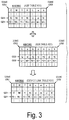
- FIG. 3 schematically illustrates a relationship among the input profile 610 , the output profile 620 , and the device link profile 630 .
- the input profile 610 is data specifying a correspondence relationship between CMYK values (C i , M i , Y i , K i ) in the CMYK color space (an example of the first device dependent color space CS 1 ) corresponding to the inks used in the target printing machine 300 and Lab values (L i , a i , b i ) in the Lab color space (an example of the profile connection space (PCS) CS 3 ).
- CMYK values C i , M i , Y i , K i
- Lab values L i , a i , b i
- PCS profile connection space
- grid points GD 1 in the A2B table 611 are typically arranged in the CMYK color space at substantially equal intervals in a C axis direction, an M axis direction, a Y axis direction, and a K axis direction.
- the variable i is a variable identifying each grid point GD 1 set in the CMYK color space (CS 1 ).
- the CMYK values are an example of first coordinate values.
- the Lab values are an example of device independent coordinate values. In a case where only the input profile 610 is used, the CMYK color space (CS 1 ) is an example of an input color space CS 4 , and the Lab color space (CS 3 ) is an example of an output color space CS 5 .
- the first device dependent color space is also referred to as a first color space.
- the output profile 620 is data specifying a correspondence relationship between Lab values (L j , a j , b j ) in the Lab color space (CS 3 ) and cmyk values (c j , m j , y j , k j ) in the cmyk color space (an example of the second device dependent color space CS 2 ) corresponding to the inks used in the ink jet-type printer 200 .
- grid points GD 2 in the B2A table 621 are typically arranged in the Lab color space at substantially equal intervals in an L axis direction, an axis direction and a b axis direction.
- the variable j is a variable identifying each grid point GD 2 set in the Lab color space (CS 3 ).
- the expression “cmyk color space” is used to distinguish the color space corresponding to the inks used in the printer 200 from the color space corresponding to the inks used in the target printing machine 300 .
- the cmyk values are an example of second coordinate values.
- the Lab color space (CS 3 ) is an example of the input color space CS 4
- the cmyk color space (CS 2 ) is an example of the output color space CS 5 .
- a color reproduction region of the output color (cmyk p ) represented by the cmyk values depends on the printer 200 .
- the second device dependent color space is also referred to as a second color space.
- the device link profile 630 is data specifying a correspondence relationship between CMYK values (C i , M i , Y i , K i ) in the CMYK color space (CS 1 ) and cmyk values (c i , m i , y i , k i ) in the cmyk color space (CS 2 ).
- each grid point GD 1 in a device link table 631 is a corresponding grid point in the A2B table 611 of the input profile 610 .
- the variable i is a variable identifying each grid point GD 1 set in the CMYK color space (CS 1 ).
- each grid point GD 1 in the device link table 631 may differ from a grid point in the A2B table 611 of the input profile 610 .
- the device link profile 630 is acquired by merging the input profile 610 (particularly the A2B table 611 ) and the output profile 620 (particularly the B2A table 621 ).
- the CMYK color space (CS 1 ) is an example of the input color space CS 4
- the cmyk color space (CS 2 ) is an example of the output color space CS 5 .
- the conversion table included in each of the profiles 610 , 620 , and 630 is not limited to a single conversion table but may be a combination of a plurality of conversion tables such as a combination of a one-dimensional conversion table, a three- or four-dimensional conversion table, and a one-dimensional table.
- the conversion tables illustrated in FIG. 3 may directly illustrate three- or four-dimensional conversion tables included in the profiles 610 , 620 , and 630 or illustrate a combination of a plurality of conversion tables included in the profiles 610 , 620 , and 630 .
- the grid points mean virtual points arranged in the input color space, and the output coordinate values corresponding to the position of each grid point in the input color space is assumed to be stored at the grid point.
- the technique includes not only even arrangement of a plurality of grid points in the input color space but also uneven arrangement of a plurality of grid points in the input color space.
- FIG. 4 schematically illustrates the structure of the profile 500 , particularly the input profile 610 and the output profile 620 .
- the profile 500 illustrated in FIG. 4 is an ICC profile and includes a profile header 510 and a tag table 520 .
- the profile 500 includes tags 521 that are information used to convert color information between the PCS and the device dependent color space.
- the tags 521 may include private tags 523 used to customize the profile 500 .
- A2Bx tags for the devices ( 300 and 200 ) include, as element data 530 , a color conversion table used to convert the device dependent color space (CMYK color space or cmyk color space) into the Lab color space.
- B2Ax tags for the devices ( 300 and 200 ) include, as the element data 530 , a color conversion table used to convert the Lab color space into the device dependent color space (CMYK color space or cmyk color space).
- An A2B0 tag and a B2A0 tag illustrated in FIG. 4 are information used for a Perceptual color conversion.
- the perceptual color conversion focuses on tone reproduction and is thus mostly used for a conversion of photographic images with a wide color gamut.
- An A2B1 tag and a B2A1 tag illustrated in FIG. 4 are information used for a Media-Relative Colorimetric color conversion or an Absolute Colorimetric color conversion.
- the colorimetric color conversion is faithful to colorimetric values, and is thus mostly used for a conversion for digital-proof color calibration output for which accurate color matching is desired.
- An A2B2 tag and a B2A2 tag illustrated in FIG. 4 are information used for a color conversion focusing on Saturation.
- the color conversion focusing on saturation focuses more on saturation of colors than on the accuracy of hue and is mostly used for a conversion of graph display and the like in business graphics.
- FIG. 5 illustrates a color conversion module setting process to be executed by the host apparatus 100 illustrated in FIG. 1 .
- the host apparatus 100 executes a plurality of processes in parallel based on multitasking. The processes described in the specific example may be properly changed, e.g., reordered.
- the color conversion module setting process includes setting one of the one or more color conversion modules 700 stored in the storage area 114 a , as the target module 710 that is a color conversion module to be used.
- the color conversion module setting process corresponds to the module setting step ST 1 , the module setting function FU 1 , and the module setting unit U 1 .
- the host apparatus 100 acquires information about the one or more color conversion modules 700 stored in the storage area 114 a set as an area where the color conversion modules are stored (step S 102 , the description of “step” is hereinafter omitted).
- the information about the color conversion modules 700 may be information identifying each color conversion module 700 , and may include information representing the vendor of the RIP 400 (see FIG. 5 ) and the name of a typical file for the color conversion module 700 .
- the host apparatus 100 After acquiring the information about the color conversion modules 700 , the host apparatus 100 causes the display apparatus 130 to display a module selection section 760 in which the list LT 0 of the color conversion modules 700 can be displayed based on the information (S 104 ).
- FIG. 5 schematically illustrates the module selection section 760 displayed by the display apparatus 130 .
- the module selection section 760 is a pull-down user interface, and the list LT 0 of the color conversion modules 700 is displayed in the module selection section 760 as a pull-down menu.
- the list LT 0 illustrated in FIG. 5 includes a “Company A RIP” using the color conversion module 701 , a “Company B RIP” using the color conversion module 702 , and a “Company C RIP” using the color conversion module 703 .
- the host apparatus 100 After outputting the information of the module selection section 760 , the host apparatus 100 accepts, via the input device 115 , an operation of selecting, from the list LT 0 in the module selection section 760 , the target module 710 that is a color conversion module to be used (S 106 ).
- the user may perform, via the input device 115 , the operation of selecting the target module 710 to be used, from the list LT 0 displayed in the pull-down menu.
- FIG. 5 illustrates that “Company A RIP” i.e., the color conversion module 701 , has been selected as the target module 710 .
- the host apparatus 100 accepts the operation of determining the target module 710 by selection from the list LT 0 .
- the to-be-used module 710 may be automatically set based on the to-be-adjusted profile 550 selected from the profile 500 regardless of the operation.
- FIG. 25 illustrates another color conversion module setting process to be executed by the host apparatus 100 . The process illustrated in FIG. 25 uses the information of the to-be-adjusted profile 550 and may thus be executed immediately after the to-be-adjusted profile 550 is set in S 204 of a profile adjustment process described below (see FIG. 12 ).
- the host apparatus 100 may read the to-be-adjusted profile 550 to acquire the RIP vendor name from the private tag 523 (S 122 ).
- the host apparatus 100 searches the one or more color conversion modules 700 stored in the storage area 114 a to find a color conversion module in which the RIP vendor name acquired in S 122 is described, and determines the found color conversion module to be the to-be-used module 710 (S 124 ).
- the host apparatus 100 may subsequently execute processes in S 108 to S 114 illustrated in FIG. 5 .
- the color conversion module in which the RIP vendor name acquired in S 122 is described may be stored in the storage area 114 a .
- the color conversion module in which the RIP vendor name is described may be set as an initial value for the target module 710 and processes in S 102 to S 114 illustrated in FIG. 5 may then be executed.
- the information for identifying the color conversion module is not limited to the RIP vendor name but may be replaced with any of various elements such as a software name which allow the target module 710 to be determined.
- the host apparatus 100 After accepting the target module 710 in S 106 illustrated in FIG. 5 or automatically determining the target module 710 in S 124 illustrated in FIG. 25 , the host apparatus 100 stores, in the storage device 114 (or the RAM 113 or the like), the module setting information 750 indicating the target module 710 (S 108 ). As described above, the host apparatus 100 sets the target module 710 .
- the process in S 110 and the subsequent steps may be omitted.
- the color conversion module 709 (see FIG. 2 ) used for the RIP 400 installed in the host apparatus 100 may be precluded from being selected from the module selection section 760 . The reason will be described below.
- FIG. 6 is a diagram schematically illustrating an example of specification information 770 about the color conversion modules used by each RIP.
- “Company A RIP”, “Company B RIP”, “Company C RIP”, and “Company D RIP” represent the names of the RIPs.
- “Interpolation method” represents n-point interpolation in a three-dimensional color conversion table (hereinafter referred to as n 3 -point interpolation).
- DLT indicates the device link table 631
- “Number of grip points in DLT” indicates the number of grid points in axis directions (C axis direction, M axis direction, Y axis direction, and K axis direction) in the CMYK color space (CS 1 ) of the device link table 631
- the color conversion module 701 used for the “Company A RIP” adopts the “8-point interpolation” as a color conversion interpolation method, adopts a “direct conversion” as a color conversion path (an example of the second conversion setting), and adopts “17” as the number of grid points in the axis directions in the input color space of the device link table 631 .
- the color conversion module 702 used for the “Company B RIP” adopts the “4-point interpolation” as a color conversion interpolation method, adopts a “sequential conversion” as a color conversion path (an example of the first conversion setting), and adopts “33” as the number of grid points in the axis directions in the input color space of the device link table 631 .
- FIG. 7 schematically illustrates the structure of the device link table 631 .
- a lower portion of FIG. 7 schematically illustrates the positions of grid points GD 3 in the CMYK color space (CS 1 ).
- the CMYK color space is a four-dimensional color space, and thus, FIG. 7 illustrates a three-dimensional virtual space formed by a C axis, an M axis, and a Y axis.
- the number of grid points in the device link table 631 may be changed, and thus, grid points GD 1 in the device link table 631 illustrated in FIG. 3 are denoted by the different reference numeral in FIG. 7 .
- the grid points GD 3 in the device link table 631 are typically arranged in the CMYK color space at substantially equal intervals in the C axis direction, the M axis direction, the Y axis direction, and the K axis direction.
- the number of grid points GD 3 in the C axis direction is denoted as Gc
- the number of grid points GD 3 in the M axis direction is denoted as Gm
- the number of grid points GD 3 in the Y axis direction is denoted as Gy.
- the number of grip points GD 3 in the K axis direction is denoted as Gk.
- the number of grid points in the device link table 631 is Gc ⁇ Gm ⁇ Gy ⁇ Gk.
- Gc, Gm, Gy, and Gk may be changed.
- grid points GD 1 in the A2B table 611 (see FIG. 3 ) of the input profile 610 are typically arranged in the CMYK color space at substantially equal intervals in the C axis direction, the M axis direction, the Y axis direction, and the K axis direction.
- the numbers of grid points GD 1 in the C, M, Y, and K axis directions are denoted as Gc, Gm, Gy, and Gk
- the number of grid points in the four-dimensional A2B table 611 is Gc ⁇ Gm ⁇ Gy ⁇ Gk.
- the A2B table of the output profile 620 is also a four-dimensional color conversion table, and has a similar number of grid points.
- Grid points GD 2 in the B2A table 621 of the output profile 620 are typically arranged in the Lab color space (CS 3 ) at substantially equal intervals in an L axis direction, an axis direction and a b axis direction.
- the numbers of grid points GD 2 in the L, a, and b axis directions are denoted as GL, Ga, and Gb
- the number of grid points in the three-dimensional B2A table 621 is GL ⁇ Ga ⁇ Gb.
- the B2A table of the input profile 610 is also a three-dimensional color conversion table, and has a similar number of grid points.
- FIGS. 8A to 8D are diagrams schematically illustrating an example of n-point interpolation (n is an integer of 4 or larger) in a three-dimensional color conversion table or a virtual space.
- n-point interpolation refers to interpolation executed based on output coordinate values and weight coefficients for each grid point used GD 10 when output coordinate values are obtained that corresponds to the input coordinate values Ip at a position included in a polyhedron including a plurality of grid points used GD 10 as vertexes.
- the weight coefficient for each grid point GD 10 may be determined by a well-known method. For example, it is assumed that Li is a distance from the position of the set of input coordinate values Ip to each grid point GD 10 .
- the variable i in this case is a variable that identifies the grid point used GD 10 .
- the sum of reciprocals 1/Li of the distances may be defined as S 1/Li
- the weight for each grid point GD 10 may be defined as 1/Li/S 1/Li
- the sum of the output coordinate values for the grid points GD 10 multiplied by the weights may be the output coordinate values corresponding to the input coordinate values Ip.
- each weight coefficient may be, e.g., the volume ratio of solids into which a solid including the grid points GD 10 as vertexes is divided by a plane passing through the position of the set of input coordinate values Ip.
- rectangular interpolation that is 8-point interpolation is a calculation including dividing, for each axis of the input color space, the grid 900 into eight rectangular parallelepipeds by a plane orthogonal to the axis direction and setting the weight coefficient for each grid point GD 10 equal to the volume ratio of each resultant rectangular parallelepiped.
- FIG. 9 is a diagram schematically illustrating an example of n-point interpolation in a four-dimensional color conversion table.
- the position of the set of input coordinate values Ip (Cp, Mp, Yp, Kp) is denoted by a filled triangle mark on the K axis in the CMYK color space (CS 1 ).
- the positions of grid points GD 0 adjacent to the set of input coordinate values Ip on opposite sides are denoted by K1 and K2.
- K1 ⁇ K2 the positions of grid points GD 0 adjacent to the set of input coordinate values Ip on opposite sides.
- K1 ⁇ K2 K1 ⁇ K2.
- Kp ⁇ K 1 K 2 ⁇ Kp
- Kr Kr :(1 ⁇ Kr ). In this case, 0 ⁇ Kr ⁇ 1.
- the final output coordinate values (cp, mp, yp, kp) corresponding to the input coordinate values Ip may be determined by applying, to the input coordinate values Ip, weights corresponding to the position of the set of input coordinate value Ip on the K axis.
- cp (1 ⁇ Kr ) ⁇ c 1+ Kr ⁇ c 2
- mp (1 ⁇ Kr ) ⁇ m 1+ Kr ⁇ m 2
- yp (1 ⁇ Kr ) ⁇ y 1+ Kr ⁇ y 2
- kp (1 ⁇ Kr ) ⁇ k 1+ Kr ⁇ k 2
- an interpolation calculation may be performed in which four grid points surrounding the set of input coordinate values Ip are selected from the four-dimensional color conversion table.
- the four-dimensional color conversion table such as the A2B table 611 of the input profile 610 or the A2B table of the output profile 620 may similarly be used for the interpolation calculation.
- FIG. 10 schematically illustrates an example of switching between color conversion paths.
- the RIP 400 is used to convert input coordinate values CMYK in in the CMYK color space (CS 1 ) into output coordinate values cmyk p in the cmyk color space (CS 2 ), the following conversion paths are possible.
- the first conversion path is a path through which the input coordinate values CMYK in are converted into PCS values Lab s with reference to the A2B table 611 of the input profile 610 and through which the PCS values Lab s is further converted into output coordinate values cmyk p with reference to the B2A table 621 of the output profile 620 .
- the first conversion path corresponds to a first conversion setting.
- the second conversion path is a path through which the input coordinate values CMYK in are directly converted into the output coordinate values cmyk p with reference to the device link table 631 .
- the second conversion path corresponds to a second conversion setting.
- the first conversion path involves a color conversion process including accurate reproduction, in the printer 200 , of color reproduction characteristics of the target printing machine 300 .
- the first conversion path involves execution of both the color conversion process referring to the A2B table 611 and the color conversion process referring to the B2A table 621 , and thus, the entire process correspondingly takes much time.
- the second conversion path needs only one color conversion process referring to the device link table 631 , into which the A2B table 611 and the B2A table 621 are combined, correspondingly reducing the time for processing.
- the combination of the A2B table 611 and the B2A table 621 results in a reduced color conversion accuracy.
- FIG. 10 illustrates, as an example of the specification of the color conversion module 700 , 17 4 grid points in the A2B table 611 and 33 3 grid points in the B2A table 621 .
- the A2B table 611 differs from the B2A table 621 in the number of grid points in each axis direction. This is to set the number of grid points in the A2B table 611 in each axis direction smaller than the number of grid points in the B2A table 621 in each axis direction to prevent an excessive increase in the amount of data in the A2B table 611 , which has a relatively large number of dimensions.
- the number of grid points in the A2B table 611 may be equal to the number of grid points in the B2A table 621 .
- FIG. 10 illustrates, as an example of the specification of the color conversion module 700 , 17 4 grid points in the device link table 631 .
- the number of grid points in the device link table 631 may be the same as or different from the number of grid points in any other conversion table
- the interpolation method, the conversion path, or the number of grids is unknown as is the case with the “Company D RIP” illustrated in FIG. 6 .
- a certain color conversion module included in the color conversion modules 700 is suitably allowed to be customized to the color conversion module 709 .
- the user may set the interpolation method, the conversion path, and the number of grid points.
- the host apparatus 100 branches the process depending on whether to customize the target module 710 to be used.
- the host apparatus 100 determines a relevant condition to have been met and causes the display apparatus 130 to display such a customized screen 780 as illustrated in FIG. 11 (S 112 ).
- the host apparatus 100 ends the color conversion module setting process.
- FIG. 11 schematically illustrates a customized screen 780 .
- the customized screen 780 includes an interpolation method selection section 781 , a conversion path selection section 782 , a number-of-grid-points selection screen 783 , a save button 786 , and a “Back to Initial Settings” button 787 .
- the host apparatus 100 accepts, via the input device 115 , operations on the selection columns 781 to 783 and the buttons 786 and 787 .
- the host apparatus 100 adds, to the module setting information 750 , the interpolation method, the interpolation path, and the number of grid points accepted through the selection sections 781 to 783 (S 114 ) and ends the color conversion module setting process.
- a plurality of selection items in the interpolation method selection section 781 illustrated in FIG. 11 include “4-point interpolation”, “5-point interpolation”, “6-point interpolation”, and “8-point interpolation”.
- the “4-point interpolation” means that 4-point interpolation is adopted to calculate output coordinate values in a three-dimensional color conversion table
- the “5-point interpolation” means that 5-point interpolation is adopted to calculate output coordinate values in a three-dimensional color conversion table
- the “6-point interpolation” means that 6-point interpolation is adopted to calculate output coordinate values in a three-dimensional color conversion table
- the “8-point interpolation” means that 8-point interpolation is adopted to calculate output coordinate values in a three-dimensional color conversion table.
- the host apparatus 100 accepts, via the interpolation method selection section 781 , a setting for a target interpolation method 781 a to be used which is included in possible n-point interpolation methods for obtaining the output coordinate values when the target module 710 executes a color conversion process.
- the conversion path selection section 782 illustrated in FIG. 11 includes a “sequential conversion” and a “direct conversion”.
- the “sequential conversion” means a first conversion setting for a color conversion on the first conversion path involving passage through the Lab color space (CS 3 ).
- the “direct conversion” means a second conversion setting for a color conversion on the second conversion path avoiding the passage through the Lab color space (CS 3 ).
- the host apparatus 100 accepts, via the conversion path selection section 782 , a selection of the first conversion setting involving the passage through the Lab color space (CS 3 ) or the second conversion setting avoiding the passage through the Lab color space (CS 3 ) when the input coordinate values CMYK in are converted into the output coordinate values cmyk p .
- the selected conversion path is set as a target conversion path 782 a .
- the conversion path selection section 782 in FIG. 11 illustrates that the “sequential conversion” has been selected as the target conversion path 782 a.
- the number-of-grid-points selection section 783 illustrated in FIG. 11 includes “13”, “17”, and “33”.
- the “13”, the “17”, and the “33” respectively mean that the number of grid points in the device link table 631 in each axis direction is set to 13, 17, and 33.
- the host apparatus 100 accepts, via the number-of-grid-points selection section 783 , the setting for the number of grid points in the to-be-adjusted profile to be created.
- the selected number of grid points is set as the target number-of-grid-points 783 a .
- the number-of-grid-points selection section 783 in FIG. 11 illustrates that the “17” has been selected as the target number-of-grid-points 783 a.
- the set target module 710 is used to adjust the profile 500 .
- FIG. 12 and FIG. 13 illustrate a profile adjustment process to be executed by the host apparatus 100 illustrated in FIG. 1 .
- FIG. 14 illustrates an example of a user interface (UI) screen 800 displayed in step S 202 in FIG. 12 .
- the profile adjustment process illustrated in FIG. 12 and FIG. 13 corresponds to the profile adjustment step ST 3 , the profile adjustment function FU 3 , and the profile adjustment unit U 3 .
- S 304 to S 308 and S 316 referring to the target module 710 correspond to the color conversion step ST 2 , the color conversion function FU 2 , and the color conversion unit U 2 .
- the host apparatus 100 causes the display apparatus 130 to display the UI screen 800 illustrated in FIG. 14 (S 202 ).
- the UI screen 800 includes an input profile selection section 811 , an output profile selection section 812 , a device link profile selection section 813 , a to-be-adjusted profile specification section 820 , a to-be-adjusted color space selection section 830 , a target acceptance area 840 , a “specify based on image” button 841 , an add button 842 , a delete button 843 , an adjustment data selection section 845 , a chart print button 846 , a colorimetry button 847 , an adjustment range specification section 850 , an intent specification section 860 , an adjustment execute button 870 , a history load button 881 , and a history save button 882 .
- the host apparatus 100 accepts operations on any of the above-described sections and buttons through the input device 115 (S 204 ), and when accepting an operation on the adjustment execution button 870 , advances the process to S 304 .
- the host apparatus 100 can cause the display apparatus 130 to display a list of the input profiles 610 stored in the storage device 114 .
- the host apparatus 100 accepts, from the input device 115 , one input profile in the displayed list of the input profiles 610 as an input profile for color conversion.
- the host apparatus 100 can cause the display apparatus 130 to display a list of the output profiles 620 stored in the storage device 114 .
- the host apparatus 100 accepts, from the input device 115 , one output profile in the displayed list of the output profiles 620 as an output profile for color conversion.
- the host apparatus 100 can cause the display apparatus 130 to display a list of the device link profiles 630 stored in the storage device 114 .
- the host apparatus 100 accepts, from the input device 115 , one output profile in the displayed list of the device link profiles 630 as an output profile for color conversion.
- the host apparatus 100 sets, as the to-be-adjusted profile, the profile corresponding to the selection section via which the operation has been accepted, and causes the display apparatus 130 to display information indicating the to-be-adjusted profile on the to-be-adjusted profile specification section 820 .
- the input profile 610 and the output profile 620 are selected in the selection sections 811 and 812 as illustrated in FIG. 14
- one of a plurality of specification items in the to-be-adjusted profile specification section 820 may be selected.
- the plurality of specification items includes the input profile 610 , the output profile 620 , and the device link profile 630 .
- CMYK values are converted into cmyk values with reference to the selected input profile 610 and output profile 620 .
- a process for generating the device link profile 630 from the input profile 610 and the output profile 620 is executed (see FIG. 14 ).
- CMYK values are converted into cmyk values with reference to the device link profile 630 .
- one of the specification items including the profiles 610 , 620 , and 630 may be selected in the to-be-adjusted profile specification section 820 .
- CMYK values are converted into cmyk values with reference to the selected input profile 610 and output profile 620 .
- CMYK values are converted into cmyk values with reference to the selected device link profile 630 .
- a plurality of selection items in the to-be-adjusted color space selection section 830 illustrated in FIG. 14 include “input data”, “output data”, and “PCS value”.
- the “input data” is an item for selecting the CMYK color space (CS 1 ) as a to-be-adjusted color space CS 6 .
- the “output data” is an item for selecting the cmyk color space (CS 2 ) as the to-be-adjusted color space CS 6 .
- the “PCS value” is an item for selecting the Lab color space (CS 3 ) as the to-be-adjusted color space CS 6 .
- the host apparatus 100 accepts, from the input device 115 , one of the “input data”, the “output data”, and the “PCS value” as the to-be-adjusted color space CS 6 .
- the plurality of selection items in the to-be-adjusted color space selection section 830 may lack “output data”.
- the plurality of selection items in the to-be-adjusted color space selection section 830 may lack “input data”.
- the host apparatus 100 executes a process for changing the input item of the target acceptance area 840 according to the selection in the to-be-adjusted color space selection section 830 . Furthermore, the host apparatus 100 executes a process for changing the input item of the target acceptance area 840 according to the selection in the adjustment data selection section 845 .
- the adjustment data selection section 845 either one of “absolute value” and “relative value” can be selected.
- the “absolute value” is an option allowing the adjustment target T 0 to be accepted as a coordinate value in the color space.
- the “relative value” is an option allowing the adjustment target T 0 to be accepted as a difference from the current coordinate value in the color space.
- the host apparatus 100 When accepting the “relative value” in the adjustment data selection section 845 , the host apparatus 100 causes an input section for the coordinate values ( ⁇ L, ⁇ a, ⁇ b) of the adjustment target T 0 , as relative values (denoted by ⁇ Lab T-p ) relative to the current coordinate values in the PCS CS 3 , to be displayed in the target acceptance area 840 , as illustrated in FIG. 14 .
- the host apparatus 100 when accepting the “absolute value” in the adjustment data selection section 845 , the host apparatus 100 causes an input section for the coordinate values (denoted by T_L, T_a, T_b) of the adjustment target T 0 along with a display section for the current coordinate values (denoted by C_L, C_a, C_b) in the PCS CS 3 to be displayed in the target acceptance area 840 .
- the host apparatus 100 When accepting the “relative value” in the adjustment data selection section 845 , the host apparatus 100 causes an input section for the coordinate values (denoted by ⁇ C, ⁇ M, ⁇ Y, ⁇ K) of the adjustment target T 0 as relative values (denoted by ⁇ CMYK T-p ) relative to the current coordinate values in the CMYK color space (CS 1 ), to be displayed in the target acceptance area 840 .
- the host apparatus 100 when accepting the “absolute value” in the adjustment data selection section 845 , the host apparatus 100 causes an input section for the coordinate values (denoted by T_C, T_M, T_Y, T_K) of the adjustment target T 0 along with a display section for the current coordinate values (denoted by C_C, C_M, C_Y, C_K) in the CMYK color space (CS 1 ) to be displayed in the target acceptance area 840 .
- the host apparatus 100 When accepting the “relative value” in the adjustment data selection section 845 , the host apparatus 100 causes an input section for the coordinate values (denoted by ⁇ c, ⁇ m, ⁇ y, ⁇ k) of the adjustment target T 0 as relative values (denoted by ⁇ cmyk T-p ) relative to the current coordinate values in the cmyk color space (CS 2 ) to be displayed in the target acceptance area 840 .
- the host apparatus 100 when accepting the “absolute value” in the adjustment data selection section 845 , the host apparatus 100 causes an input section for the coordinate values (denoted by T_c, T_m, T_y, T_k) of the adjustment target T 0 along with a display section for the current coordinate values (denoted by C_c, C_m, C_y, C_k) in the cmyk color space (CS 2 ) to be displayed in the target acceptance area 840 .
- the adjustment point P 0 for which the adjustment target T 0 is to be set is set in the CMYK color space (CS 1 ).
- the CMYK color space is a four-dimensional color space, and thus, FIG. 15 illustrates a three-dimensional virtual space formed by the C axis, the M axis, and the Y axis. Note that although FIG. 15 illustrates two adjustment points P 01 and P 02 as the adjustment point P 0 , one, or three or more adjustment points P 0 may be set.
- the host apparatus 100 causes the display apparatus 130 to display a screen schematically depicting the CMYK color space (CS 1 ), and acquires CMYK values corresponding to an operation through the input device 115 to update the information of the target acceptance area 840 .
- the host apparatus 100 provides a corresponding ID (identification information) and causes the acquired CMYK values, Lab values obtained from the CMYK values, and the like to be displayed in the target acceptance area 840 in association with the ID.
- the add button 842 is operated, the host apparatus 100 provides an additional ID, and adds, to the target acceptance area 840 , an input section corresponding to the added ID.
- the delete button 843 is operated, the host apparatus 100 accepts a specification of an ID to be deleted, and deletes the input section corresponding to the specified ID.
- the host apparatus 100 when accepting an operation on the chart print button 846 , the host apparatus 100 generates print data of the color chart CH 1 with color patches each representing the color of corresponding adjustment point P 0 and transmits the print data to the printer 200 .
- the printer 200 receives the print data and then prints, on a print substrate ME 1 , the color chart CH 1 with the color patches each representing the color of corresponding adjustment point P 0 .
- the host apparatus 100 instructs the colorimetric apparatus 120 to execute a colorimetric process on each patch of the color chart CH 1 .
- the colorimetric apparatus 120 receives the instruction, then executes a colorimetric process on each patch of the color chart CH 1 , and transmits the colorimetric values (Lab p ) of each patch to the host apparatus 100 .
- the host apparatus 100 receives the colorimetric values (Lab p ) and may then cause the display apparatus 130 to display the colorimetric values (Lab p ) or cause the printer 200 to print the colorimetric values (Lab p ).
- a user may view the output colorimetric values (Lab p ) and input the adjustment target T 0 to the target acceptance area 840 .
- the host apparatus 100 may automatically input the colorimetric values (Lab p ) of each patch to an input section for the target T 0 .
- the host apparatus 100 may calculate differences between the components L, a, and b of the target colorimetric values Lab T and the components L, a, and b of the current colorimetric values Lab p and automatically input the differences to the input section for the target T 0 .
- the host apparatus 100 when accepting an operation on the history load button 881 , the host apparatus 100 reads an adjustment history stored in the storage device 114 , and adds the adjustment history to the target acceptance area 840 .
- the host apparatus 100 stores the information of the target acceptance area 840 in the storage device 114 as an adjustment history.
- the host apparatus 100 accepts, in the adjustment range specification section 850 , an input of a Radius on the assumption that the adjustment point P 0 is a base point.
- the radius is represented, e.g., as a relative Euclid distance value 0 to 100% in the first color space CS 1 . Consequently, the adjustment range A 0 of the input profile 610 is specified in the first color space CS 1 .
- FIG. 15 schematically illustrates an example of the adjustment range A 0 in a case where the Radius is specified.
- the adjustment range A 0 is set for each adjustment point P 0 .
- an adjustment range A 01 is set for the adjustment point P 01
- an adjustment range A 02 is set for the adjustment point P 02 .
- the host apparatus 100 is capable of accepting, in the target acceptance area 840 , an input of the adjustment range A 0 of each adjustment point P 0 .
- the host apparatus 100 accepts, in the intent specification section 860 , a specification of a rendering intent for defining the correspondence relationship for the input profile 610 .
- a plurality of specification items for the intent specification section 860 illustrated in FIG. 14 are three types of items: “Perceptual”, “Relative Colorimetric”, and “Saturation”.
- the specification items may include “Absolute Colorimetric”, or any of “Perceptual”, “Relative Colorimetric”, and “Saturation” may be omitted from the specification items.
- FIG. 14 illustrates an example where “Perceptual” is specified as a specified intent.
- the host apparatus 100 executes a process in S 206 in FIG. 12 and the subsequent steps.
- the host apparatus 100 first branches the process depending on whether or not the color conversion is from CMYK values into cmyk values (S 206 ). In a case where only the input profile 610 or only the output profile 620 is set in the profile selection sections 811 to 813 in FIG. 14 , the color conversion is not from CMYK values into cmyk values. In this case, the host apparatus 100 sets the input profile 610 or the output profile 620 selected in the profile selection sections 811 and 812 , in the target module 710 as a profile for color conversion (S 218 ), and advances the process to S 304 in FIG.
- the color conversion is from CMYK values into cmyk values.
- the host apparatus 100 advances the process to S 208 .
- the host apparatus 100 branches the process depending on whether or not the conversion path from CMYK values to cmyk values involves a “sequential conversion” (first conversion setting) including the passage through the Lab color space (CS 3 ) or a “direct conversion” (second conversion setting) avoiding the passage through the Lad color space (CS 3 ).
- the conversion path involves the “sequential conversion”.
- the host apparatus 100 sets the combination of the input profile 610 with the output profile 620 selected in the profile selection sections 811 and 812 , in the target module 710 as a profile for color conversion (S 210 ). The host apparatus 100 subsequently advances the process to S 304 in FIG. 13 .
- the host apparatus 100 branches the process depending on whether or not the device link profile 630 is set in the device link profile selection section 813 (S 212 ).
- the host apparatus 100 advances the process to S 216 .
- the host apparatus 100 In a case where the device link profile 630 is not set, the host apparatus 100 generates the device link profile 630 with the number of grid points set in the target module 710 , from the input profile 610 and the output profile 620 set in the profile selection sections 811 and 812 (S 214 ). The host apparatus 100 subsequently advances the process to S 216 .
- the process in S 214 described above may be executed, e.g., as follows.
- the A2B table 611 is read from the input profile 610
- the B2A table 621 is read from the output profile 620 .
- Gc ⁇ Gm ⁇ Gy ⁇ Gk grid points GD 3 in the device link table 631 are then set in accordance with the number of grid points GD set in the target module 710 .
- the number of grid points set in the target module 710 is “33”
- Input coordinate values (denoted as Ci, Mi, Yi, Ki) for each grid point GD 3 are then converted into Lab values (denoted as Li, ai, bi) with reference to the A2B table 611 .
- An interpolation calculation is executed as needed to obtain the Lab values Li, ai, and bi in accordance with the interpolation method set in the target module 710 .
- the Lab values (Li, ai, bi) are then converted into cmyk values (denoted as ci, mi, yi, and ki) with reference to the B2A table 621 .
- An interpolation calculation is executed as needed to obtain the cmyk values ci, mi, yi, ki in accordance with the interpolation method set in the target module 710 .
- the cmyk values (ci, mi, yi, ki) are then stored, as output coordinate values, at the grid point GD 3 corresponding to the input coordinate values (Ci, Mi, Yi, Ki) to generate a device link table 631 .
- the device link table 631 is stored in the device link profile 630 to generate a device link profile 630 with the number of grid points set in the target module 710 .
- a device link profile 630 with the number of grid points set in the target module 710 is therefore generated regardless of the number of grid points in the A2B table 611 or the B2A table 621 .
- the host apparatus 100 sets the device link profile 630 in the target module 710 as a profile for color conversion.
- the host apparatus 100 sets the device link profile 630 generated in the processing of S 214 , in the target module 710 as a profile for color conversion.
- the device link profile 630 selected in the device link profile selection section 813 is set in the target module 710 as a profile for color conversion.
- the host apparatus 100 subsequently advances the process to S 304 in FIG. 13 .
- a process in S 304 and the subsequent steps in FIG. 13 will be described below.
- Perceptual is specified in the intent specification section 860
- the host apparatus 100 uses, in the process in S 304 and the subsequent steps, information in the profile 500 based on a perceptual color conversion (e.g., the information indicated by the A2B0 tag and the B2A0 tag illustrated in FIG. 4 ).
- Relative Colorimetric is specified in the intent specification section 860
- the host apparatus 100 uses, in the process in S 304 and the subsequent steps, information in the profile 500 , based on a relative colorimetric color conversion (e.g., the information indicated by the A2B1 tag and the B2A1 tag illustrated in FIG.
- the host apparatus 100 uses, in the process in S 104 and the subsequent steps, information in the profile 500 , based on a saturation-oriented color conversion (e.g., the information indicated by the A2B2 tag and the B2A2 tag illustrated in FIG. 4 ).
- a saturation-oriented color conversion e.g., the information indicated by the A2B2 tag and the B2A2 tag illustrated in FIG. 4 ).
- the host apparatus 100 invokes the target module 710 in which the color conversion profile (including the combination of profiles) is set to obtain the current output values CurrentOut (S 304 ). This operation is performed for adjustment based on the output colors (cmyk p ) corresponding to the colors of an output image IMO formed on the print substrate ME 1 .
- Each of the color conversion modules 700 causes the host apparatus 100 to implement a function at least to receive, as arguments, input coordinate values in the input color space CS 4 for a profile to be used for color conversion and to return output coordinate values in the output color space CS 5 for the profile.
- the target module 710 set as the color conversion module to be used refers to the profile to be used for color conversion, to cause the host apparatus 100 to implement a function to convert the input coordinate values in the input color space CS 4 into the output coordinate values in the output color space CS 5 in accordance with the set target interpolation method 781 a.
- the input profile 610 is automatically set as the to-be-adjusted profile 550 , as illustrated in FIG. 16A .
- the input values Input for each adjustment point P 0 are CMYK values (denoted as Cp, Mp, Yp, Kp), and the current output values CurrentOut are Lab values (denoted as Lp, ap, bp).
- the variable p is a variable that identifies the adjustment point P 0 .
- a conversion in accordance with the profile executed by the color conversion module 700 is to be represented by f icc (a first argument, a second argument, a third argument).
- the first argument represents a profile used.
- the first argument includes InputProfile representing an input profile, OutputProfile representing an output profile, and DLProfile representing a device link profile.
- the second argument represents a color conversion table used for the profile represented by the first argument.
- the second argument includes A2B representing a conversion from a device color to a device independent color, B2A representing a conversion from a device independent color to a device color, and A2B0 representing a conversion using the device link table.
- the third argument Input represents the input values (CMYK, RGB, Lab, or the like) of the adjustment point P 0 .
- the host apparatus 100 causes the target module 710 in which the input profile 610 is set to execute a color conversion process. At this time, the host apparatus 100 passes, to the target module 710 , information A2B representing the A2B table 611 and the input values Cp, Mp, Yp, Kp (input coordinate values) to cause the target module 710 to execute the color conversion process, and acquires the output values Lp, ap, bp (output coordinate values) from the target module 710 as the current output values CurrentOut.
- the target module 710 refers to the A2B table 611 of the input profile 610 to cause the host apparatus 100 to implement a function to convert the input values Cp, Mp, Yp, Kp into the output values Lp, ap, bp in accordance with the set interpolation method.
- the color conversion process described below is similarly executed by invoking the target module 710 .
- the output profile 620 is automatically set as the to-be-adjusted profile 550 , as illustrated in FIG. 16B .
- the input values Input for each adjustment point P 0 are Lab values (denoted as Lp, ap, bp), and the current output values CurrentOut are cmyk values (denoted as cp, mp, yp, kp).
- the current output values CurrentOut can be calculated by the following equation (see FIG. 17 ).
- CurrentOut f icc (OutputProfile, B 2 A ,Input)
- the host apparatus 100 causes the target module 710 in which the output profile 620 is set to execute a color conversion process. At this time, the host apparatus 100 passes, to the target module 710 , information B2A representing the B2A table 621 and the input values Lp, ap, bp (input coordinate values) to cause the target module 710 to execute the color conversion process, and acquires the output values cp, mp, yp, kp (output coordinate values) from the target module 710 as the current output values CurrentOut.
- the target module 710 refers to the B2A table 621 of the output profile 620 to cause the host apparatus 100 to implement a function to convert the input values Lp, ap, bp into the output values cp, mp, yp, kp in accordance with the set interpolation method.
- the “5-point interpolation” is set as the interpolation method, a process for obtaining the output coordinate values corresponding to the input coordinate values Ip by using the output coordinate values and the weight coefficients for five grid points GD 10 at vertexes of a quadrangular pyramid including the position of the set of input coordinate values Ip, as illustrated in FIG. 8B .
- the color conversion process described below is similarly executed by invoking the target module 710 .
- the device link profile 630 is automatically set as the to-be-adjusted profile 550 , as illustrated in FIG. 16C .
- the input values Input for each adjustment point P 0 are CMYK values (Cp, Mp, Yp, Kp), and the current output values CurrentOut are cmyk values (cp, mp, yp, kp).
- the current output values CurrentOut can be calculated by the equation below (see FIG. 17 ).
- CurrentOut f icc (DLProfile, A 2 B 0,Input)
- the host apparatus 100 causes the target module 710 in which the device link profile 630 is set to execute a color conversion process. At this time, the host apparatus 100 passes, to the target module 710 , information A2B0 representing the device link table 631 and the input values Cp, Mp, Yp, Kp (input coordinate values) to cause the target module 710 to execute the color conversion process, and acquires the output values cp, mp, yp, kp (output coordinate values) from the target module 710 as the current output values CurrentOut.
- the target module 710 refers to the device link profile 630 represented by “DLProfile”, to cause the host apparatus 100 to implement a function to convert the input values Cp, Mp, Yp, Kp into the output values cp, mp, yp, kp in accordance with the set interpolation method.
- DLProfile device link profile 630 represented by “DLProfile”
- the input values Input for each adjustment point P 0 are CMYK values (Cp, Mp, Yp, Kp), and the current output values CurrentOut are cmyk values (cp, mp, yp, kp).
- the current output values CurrentOut can be calculated by the following equation (see FIG. 17 ).
- CurrentOut f icc (OutputProfile, B 2 A,f icc (InputProfile, A 2 B ,Input)
- the host apparatus 100 causes the target module 710 in which the combination of the profiles 610 and 620 is set to execute a color conversion process. At this time, the host apparatus 100 passes input values Cp, Mp, Yp, Kp (input coordinate values) to the target module 710 to cause the target module 710 to execute the color conversion process, and acquires the output values cp, mp, yp, kp (output coordinate values) from the target module 710 as the current output values CurrentOut.
- the target module 710 first refers to the A2B table 611 of the input profile 610 to cause the host apparatus 100 to implement a function to convert the input values Cp, Mp, Yp, Kp into the Lab values Lp, ap, bp in accordance with the set interpolation method.
- the target module 710 then refers to the B2A table 621 of the output profile 620 to cause the host apparatus 100 to implement a function to convert the Lab values Lp, ap, bp into the output values cp, mp, yp, kp in accordance with the set interpolation method.
- the target module 710 returns the output values cp, mp, yp, kp as a calculation result.
- the host apparatus 100 acquires the output values cp, mp, yp, kp as the current output values CurrentOut.
- the color conversion process described below is similarly executed.
- the first conversion setting involving the passage through the Lab color space (CS 3 ) allows for a color conversion process in which the printer 200 having color reproduction characteristics represented by the output profile 620 accurately reproduces color reproduction characteristics of a target printing machine.
- the target module 710 performs a color conversion referring to the set device link profile 630 .
- the device link profile 630 is obtained by combining the profiles 610 and 620 with each other in S 214 in FIG. 12 such that the resultant profile includes a plurality of grid points the number of which is equal to the number of grid points set in the target module 710 .
- CurrentOut f icc (DLProfile, A 2 B 0,Input)
- the target module 710 refers to the device link table 631 of the device link profile 630 to cause the host apparatus 100 to implement a function to convert the input values Cp, Mp, Yp, Kp into the output values cp, mp, yp, kp in accordance with the set interpolation method.
- the target module 710 returns the output values cp, mp, yp, kp as a calculation result.
- the host apparatus 100 acquires the output values cp, mp, yp, kp as the current output values CurrentOut.
- the color conversion process described below is similarly executed.
- the second conversion setting avoiding the passage through the Lab color space (CS 3 ) needs only one color conversion process referring to the device link profile 630 , into which the input profile 610 and the output profile 620 are combined, correspondingly reducing the time for processing.
- the target module 710 performs a color conversion referring to both profiles 610 and 620 .
- the target module 710 first refers to the A2B table 611 of the input profile 610 to cause the host apparatus 100 to implement a function to convert the input values Cp, Mp, Yp, Kp into the output values Lp, ap, bp in accordance with the set interpolation method.
- the target module 710 then refers to the B2A table 621 of the output profile 620 to cause the host apparatus 100 to implement a function to convert the Lab values Lp, ap, bp into the output values cp, mp, yp, kp in accordance with the set interpolation method. This allows for a color conversion process achieving accurate color reproduction.
- the target module 710 refers to the device link table 631 to cause the host apparatus 100 to implement a function to convert the input values Cp, Mp, Yp, Kp into the output values cp, mp, yp, kp in accordance with the set interpolation method. This allows for a quick color conversion process.
- the host apparatus 100 invokes, for each adjustment point P 0 input to the target acceptance area 840 , the target module 710 in which the color conversion profile (including the combination of the profiles) is set to obtain target output values TargetOut (S 306 ).
- the target output values TargetOut are obtained that correspond to the to-be-adjusted color space CS 6 specified in the to-be-adjusted color space selection section 830 .
- the target output values TargetOut are obtained for adjustment based on the output colors cmyk p corresponding to the colors of an output image IMO formed on the print substrate ME 1 .
- adjustment amounts AdjustData are added to the CMYK values (Cp, Mp, Yp, Kp) in the CMYK color space, as illustrated in FIG. 18A .
- the adjustment amounts AdjustData are represented as relative values ( ⁇ Cp, ⁇ Mp, ⁇ Yp, ⁇ Kp).
- the adjusted CMYK values are represented by (Cp+ ⁇ Cp, Mp+ ⁇ Mp, Yp+ ⁇ Yp, Kp+ ⁇ Kp).
- TargetOut f icc (InputProfile, A 2 B ,Input+AdjustData)
- the host apparatus 100 causes the target module 710 in which the input profile 610 is set to execute a color conversion process. At this time, the host apparatus 100 passes, to the target module 710 , the information A2B representing the A2B table 611 and the input values Input+AdjustData (input coordinate values) to cause the target module 710 to execute the color conversion process, and acquires the output values TargetOut (output coordinate values) from the target module 710 as the current output values CurrentOut.
- the adjustment amounts AdjustData are added to the Lab values (Lp, ap, bp) in the Lab color space, as illustrated in FIG. 18B .
- the adjustment amounts AdjustData are represented as relative values ( ⁇ Lp, ⁇ ap, ⁇ bp).
- the adjusted Lab values are represented by (Lp+ ⁇ Lp, ap+ ⁇ ap, bp+ ⁇ bp).
- TargetOut f icc (InputProfile, A 2 B ,Input)+AdjustData
- the host apparatus 100 causes the target module 710 in which the input profile 610 is set to execute a color conversion process. At this time, the host apparatus 100 passes, to the target module 710 , the information A2B representing the A2B table 611 and the input values Input (input coordinate values) to cause the target module 710 to execute the color conversion process, and acquires the output coordinate values from the target module 710 . Addition of the adjustment amounts AdjustData to the output coordinate values results in the target output values TargetOut.
- the adjustment amounts AdjustData are added to the Lab values (Lp, ap, bp) in the Lab color space, as illustrated in FIG. 18C .
- the adjustment amounts AdjustData are represented as relative values ( ⁇ Lp, ⁇ ap, ⁇ bp).
- the adjusted Lab values are represented by (Lp+ ⁇ Lp, ap+ ⁇ ap, bp+ ⁇ bp).
- TargetOut f icc (OutputProfile, B 2 A ,Input+AdjustData)
- the host apparatus 100 causes the target module 710 in which the output profile 620 is set to execute a color conversion process. At this time, the host apparatus 100 passes, to the target module 710 , the information B2A representing the B2A table 621 and the input values Input+AdjustData (input coordinate values) to cause the target module 710 to execute the color conversion process, and acquires the output values TargetOut (output coordinate values) from the target module 710 .
- the adjustment amounts AdjustData are added to the cmyk values (cp, mp, yp, kp) in the cmyk color space, as illustrated in FIG. 18D .
- the adjustment amounts AdjustData are represented as relative values ( ⁇ cp, ⁇ mp, ⁇ yp, ⁇ kp).
- the adjusted cmyk values are represented by (cp+ ⁇ cp, mp+ ⁇ mp, yp+ ⁇ yp, kp+ ⁇ kp).
- TargetOut f icc (OutputProfile, B 2 A ,Input)+AdjustData
- the host apparatus 100 causes the target module 710 in which the output profile 620 is set to execute a color conversion process. At this time, the host apparatus 100 passes, to the target module 710 , the information B2A representing the B2A table 621 and the input values Input (input coordinate values) to cause the target module 710 to execute the color conversion process, and acquires the output coordinate values from the target module 710 . Addition of the adjustment amounts AdjustData to the output coordinate values results in the target output values TargetOut.
- the adjustment amounts AdjustData are added to the CMYK values (Cp, Mp, Yp, Kp) in the CMYK color space.
- the adjustment amounts AdjustData are represented as relative values ( ⁇ Cp, ⁇ Mp, ⁇ Yp, ⁇ Kp).
- the adjusted CMYK values are represented by (Cp+ ⁇ Cp, Mp+ ⁇ Mp, Yp+ ⁇ Yp, Kp+ ⁇ Kp).
- TargetOut f icc (DLProfile, A 2 B 0,Input+AdjustData)
- the host apparatus 100 causes the target module 710 in which the device link profile 630 is set to execute a color conversion process. At this time, the host apparatus 100 passes, to the target module 710 , the information A2B0 representing the device link table 631 and the input values Input+AdjustData (input coordinate values) to cause the target module 710 to execute the color conversion process, and acquires the output values TargetOut (output coordinate values) from the target module 710 .
- the adjustment amounts AdjustData are added to the cmyk values (cp, mp, yp, kp) in the cmyk color space.
- the adjustment amounts AdjustData are represented as relative values ( ⁇ cp, ⁇ mp, ⁇ yp, ⁇ kp).
- the adjusted cmyk values are represented by (cp+ ⁇ cp, mp+ ⁇ mp, yp+ ⁇ yp, kp+ ⁇ kp).
- TargetOut f icc (DLProfile, A 2 B 0,Input)+AdjustData
- the host apparatus 100 causes the target module 710 in which the device link profile 630 is set to execute a color conversion process. At this time, the host apparatus 100 passes, to the target module 710 , the information A2B0 representing the device link table 631 and the input values Input (input coordinate values) to cause the target module 710 to execute the color conversion process, and acquires the output coordinate values from the target module 710 . Addition of the adjustment amounts AdjustData to the output coordinate values results in the target output values TargetOut.
- the adjustment amounts AdjustData are added to the CMYK values (Cp, Mp, Yp, Kp) in the CMYK color space, as illustrated in FIG. 19A .
- the adjustment amounts AdjustData are represented as relative values ( ⁇ Cp, ⁇ Mp, ⁇ Yp, ⁇ Kp).
- the adjusted CMYK values are represented by (Cp+ ⁇ Cp, Mp+ ⁇ Mp, Yp+ ⁇ Yp, Kp+ ⁇ Kp).
- TargetOut f icc (OutputProfile, B 2 A,f icc (InputProfile, A 2 B ,Input+AdjustData))
- the target module 710 first refers to the A2B table 611 of the input profile 610 to cause the host apparatus 100 to implement a function to convert the input values Cp+ ⁇ Cp, Mp+ ⁇ Mp, Yp+ ⁇ Yp, Kp+ ⁇ Kp into Lab values in accordance with the set interpolation method.
- the target module 710 then refers to the B2A table 621 of the output profile 620 to cause the host apparatus 100 to implement a function to convert the Lab values into output values in accordance with the set interpolation method.
- the target module 710 returns the output values as a calculation result.
- the host apparatus 100 acquires the output values as the target output values TargetOut. This allows for a color conversion process achieving accurate color reproduction.
- the target module 710 refers to the device link table 631 to cause the host apparatus 100 to implement a function to convert the input values Cp+ ⁇ Cp, Mp+ ⁇ Mp, Yp+ ⁇ Yp, Kp+ ⁇ Kp into output values in accordance with the set interpolation method.
- the target module 710 returns the output values as a calculation result.
- the host apparatus 100 acquires the output values as the target output values TargetOut. This allows for a quick color conversion process.
- the adjustment amounts AdjustData are added to the cmyk values (cp, mp, yp, kp) in the cmyk color space, as illustrated in FIG. 19B .
- the adjustment amounts AdjustData are represented as relative values ( ⁇ cp, ⁇ mp, ⁇ yp, ⁇ kp).
- the adjusted cmyk values are represented by (cp+ ⁇ cp, mp+ ⁇ mp, yp+ ⁇ yp, kp+ ⁇ kp).
- TargetOut f icc (OutputProfile, B 2 A,f icc (InputProfile, A 2 B ,Input))+AdjustData
- the target module 710 first refers to the A2B table 611 of the input profile 610 to cause the host apparatus 100 to implement a function to convert the input values Input into Lab values in accordance with the set interpolation method.
- the target module 710 then refers to the B2A table 621 of the output profile 620 to cause the host apparatus 100 to implement a function to convert the Lab values into output values in accordance with the set interpolation method.
- the target module 710 returns the output values as a calculation result.
- the host apparatus 100 adds the adjustment amounts AdjustData to the output values to acquire the target output values TargetOut.
- the target module 710 refers to the device link table 631 to cause the host apparatus 100 to implement a function to convert the input values Input into output values in accordance with the set interpolation method.
- the target module 710 returns the output values as a calculation result.
- the host apparatus 100 adds the adjustment amounts AdjustData to the output values to acquire the target output values TargetOut.
- the adjustment amounts AdjustData are added to the Lab values (Lp, ap, bp) in the Lab color space, as illustrated in FIG. 19C .
- the adjustment amounts AdjustData are represented as relative values ( ⁇ Lp, ⁇ ap, ⁇ bp).
- the adjusted Lab values are represented by (Lp+ ⁇ Lp, ap+ ⁇ ap, bp+ ⁇ bp).
- TargetOut f icc (OutputProfile, B 2 A,f icc (InputProfile, A 2 B ,Input)+AdjustData)
- the target module 710 first refers to the A2B table 611 of the input profile 610 to cause the host apparatus 100 to implement a function to convert the input values Input into the Lab values Lp, ap, bp in accordance with the set interpolation method.
- the target module 710 returns the output values Lp, ap, bp as a calculation result.
- the host apparatus 100 adds the adjustment amounts AdjustData to the output values La, ap, bp to acquire the adjusted Lab values Lp+ ⁇ Lp, ap+ ⁇ ap, bp+ ⁇ bp, and passes the adjusted Lab values to the target module 710 .
- the target module 710 then refers to the B2A table 621 of the output profile 620 to cause the host apparatus 100 to implement a function to convert the Lab values Lp+ ⁇ Lp, ap+ ⁇ ap, bp+ ⁇ bp into output values in accordance with the set interpolation method.
- the target module 710 returns the output values as a calculation result.
- the host apparatus 100 acquires the output values as the target output values TargetOut.
- the target output values TargetOut are acquired as in the cases (b-1-1), (b-1-2), and (b-1-3) where the combination of the profiles 610 and 620 is specified for color conversion.
- the calculation of the target output values TargetOut may be omitted in a case where the adjustment target T 0 is represented by the output coordinate values, and may be limited to a case where the adjustment target T 0 is not represented by the output coordinate values.
- the host apparatus 100 After calculating the target output values TargetOut, the host apparatus 100 acquires, for each adjustment point P 0 , input values Input_P and adjustment target values TargetOut_P in the to-be-adjusted profile 550 (S 308 ). This is to adjust the correspondence relationship between the input values and the output values in the to-be-adjusted profile 550 .
- current output values CurrentOut_P in the to-be-adjusted profile 550 are current output values CurrentOut in the specified profile.
- CurrentOut_ P CurrentOut
- the adjustment target values TargetOut_P (Lab values) in the to-be-adjusted profile 550 are determined from the target output values TargetOut (cmyk values) to allow for adjustment based on the output color cmyk p corresponding to the color of the output image IMO.
- the host apparatus 100 passes, to the target module 710 , the information OutputProfile representing the output profile 620 , the information A2B representing the A2B table of the output profile 620 , and the target output values TargetOut as the input coordinate values to cause the target module 710 to execute the color conversion process, and acquires the adjustment target values TargetOut_P from the target module 710 .
- CurrentOut_P (Lab values) in the to-be-adjusted profile 550 are represented by the following equation.
- CurrentOut_ P f icc (InputProfile, A 2 B ,Input)
- the relative values of the adjustment target T 0 are represented by TargetOut_P ⁇ CurrentOut_P.
- the target output values TargetOut in the combination of the profiles 610 and 620 are used as the adjustment target values TargetOut_P in the to-be-adjusted profile 550 .
- the input values Input_P (Lab values) in the to-be-adjusted profile 550 may be calculated from the input values Input, which are CMYK values (see FIG. 22 ).
- the host apparatus 100 passes, to the target module 710 , the information InputProfile representing the input profile 610 , the information A2B representing the A2B table 611 , and the input values Input (input coordinate values) to cause the target module 710 to execute the color conversion process, and acquires the input values Input_P in the to-be-adjusted profile 550 from the target module 710 .
- the current output values CurrentOut_P (cmyk values) in the to-be-adjusted profile 550 are the current output values CurrentOut in the combination of the profiles 610 and 620 .
- CurrentOut_ P CurrentOut
- the relative values of the adjustment target T 0 are represented by TargetOut_P ⁇ CurrentOut_P.
- the host apparatus 100 After acquiring the input values Input_P and the adjustment target values TargetOut_P in the to-be-adjusted profile 550 , the host apparatus 100 adjusts, in S 310 to S 312 , the adjustment range A 0 of the to-be-adjusted profile 550 , based on the adjustment target T 0 .
- the horizontal axis indicates input values along a certain coordinate axis of the input color space CS 4
- the vertical axis indicates output values along a certain coordinate axis of the output color space CS 5 .
- the horizontal axis corresponds to the C axis, the M axis, the Y axis, or the K axis.
- the vertical axis corresponds to the L axis, the a axis, or the b axis.
- White circles on the horizontal axis indicate grid points GD 0 .
- FIG. 23A schematically illustrates the adjustment amounts AD for each grid point GD 0 in a case where the output values are adjusted.
- the adjustment point P 0 specified by the user corresponds to the input values Input_P.
- the adjustment amounts AdjustData are added to the current output values CurrentOut_P corresponding to the input values Input_P to set the adjustment target values TargetOut_P.
- the current output values CurrentOut_P and the adjustment target values TargetOut_P are represented by cmyk values
- the adjustment amounts AdjustData are represented by the relative values of the cmyk values ( ⁇ cp, ⁇ mp, ⁇ yp, ⁇ kp).
- the current output values CurrentOut_P and the adjustment target values TargetOut_P are represented by Lab values
- the adjustment amounts AdjustData are represented by the relative values of the Lab values ( ⁇ Lp, ⁇ ap, ⁇ bp).
- An input to the adjustment range specification section 850 and the target acceptance area 840 illustrated in FIG. 14 sets the adjustment range A 0 for the adjustment amounts AdjustData.
- the adjustment amounts for the output values are maximized with respect to the input values Input_P, and the adjustment amounts are set to 0 at boundaries of the adjustment range A 0 .
- actual adjustment is performed on the grid points GD 0 in the to-be-adjusted profile 550 , and thus, the adjustment may affect a range wider than the set adjustment range A 0 .
- FIG. 23B schematically illustrates the adjustment amounts AD for each grid point GD 0 in a case where the input values are adjusted.
- the adjustment point P 0 specified by the user corresponds to the input values Input_P.
- the adjustment amounts AdjustData are added to the input value Input_P to determine output values corresponding to the input values Input_P+AdjustData.
- the output values are output values expected at the adjustment point P 0 specified by the user.
- the input values Input_P are represented by CMYK values
- the adjustment amounts AdjustData are represented by the relative values of the CMYK values ( ⁇ Cp, ⁇ Mp, ⁇ Yp, ⁇ Kp).
- the input values Input_P are represented by Lab values
- the adjustment amounts AdjustData are represented by the relative values of the Lab values ( ⁇ Lp, ⁇ ap, ⁇ bp).
- the above-described correction is performed for all the coordinate axes in the input color space CS 4 and for all the coordinate values in the output color space CS 5 .
- the adjustment amounts AD is set for each grid point GD 0 within the adjustment range A 0 .
- the horizontal axis indicates each input value
- the vertical axis indicates the adjustment amount AD for each output value.
- triangular marks on the horizontal axis indicate the grid points within the adjustment range A 0 (excluding a nearest grid point GDnearest)
- square marks on the horizontal axis indicate grid points outside the adjustment range A 0 for which the output value is not to be modified.
- the host apparatus 100 determines, for each adjustment point P 0 , an adjustment amount AD 1 for the output value for the nearest grid point GDnearest, which is closest to the adjustment point P 0 (S 310 in FIG. 13 ).
- FIG. 24A illustrates an example where the adjustment amount AD 1 for the output value is determined in a case where two adjustment points P 0 (input values Input_P) are specified on a certain coordinate axis of the input color space CS 4 .
- the adjustment amounts AdjustData for the input values Input_P are used as the adjustment amount AD 1 for the output value for the nearest grid point GDnearest without any change.
- the technique is not limited to setting, to the adjustment amount AdjustData, the adjustment amount AD 1 for the output value for the nearest grid point GDnearest.
- a plurality of adjustment points lying near one another may have the same nearest grid point GDnearest.
- the adjustment amounts AdjustData for the adjustment points may be averaged at a rate inversely proportional to a distance from the nearest grid point GDnearest to the adjustment point.
- the host apparatus 100 determines adjustment amounts AD 2 for the output values for grid points (the grid points with the triangular marks) lying within the adjustment range A 0 and around the nearest grid point GDnearest (S 312 in FIG. 13 ), as illustrated in FIG. 24B .
- an interpolation calculation is executed using a three- or four-dimensional cubic spline function.
- the adjustment amounts AD 2 for the output values for the grid points around the nearest grid point GDnearest can be determined.
- the interpolation calculation may use the four-dimensional cubic spline function.
- the interpolation calculation may use the three-dimensional cubic spline function.
- the technique is not limited to the use of the spline function for the interpolation calculation.
- the adjustment amounts AD are intended for the grid points, in a case where a plurality of adjustment points lies near one another, the same grid point may be referred to when input colors for the adjustment points are color-converted in accordance with the input profile 610 .
- the adjustment amounts AdjustData for the adjustment points are averaged for adjustment.
- the host apparatus 100 revises the to-be-adjusted profile 550 by using the determined adjustment amounts AD (S 314 in FIG. 13 ). That is, for each grid point within the adjustment range A 0 , a value obtained by adding the adjustment amount AD to the current output value may be written to the to-be-adjusted profile 550 as an updated output value.
- the updated output values are obtained by adding the adjustment amounts (denoted as ⁇ cq, ⁇ mq, ⁇ yq, ⁇ kq) to the current output values (denoted as cq, mq, yq, kq).
- the output color space CS 5 in the to-be-adjusted profile 550 is the Lab color space, and thus, the updated output values are values (Lq+ ⁇ Lq, aq+ ⁇ aq, bq+ ⁇ bq) resulting from the sum of the current output values (denoted as Lq, aq, bq) and the adjustment amounts (denoted as ⁇ Lq, ⁇ aq, ⁇ bq).
- the variable q is a variable that identifies each grid point within the adjustment range A 0 .
- the correspondence relationship for the to-be-adjusted profile 550 is adjusted to make the current output values CurrentOut in the second color space CS 2 closer to the target output values TargetOut color.
- the host apparatus 100 After updating the to-be-adjusted profile 550 , the host apparatus 100 determines, for each adjustment point P 0 input to the target acceptance area 840 , the current output values CurrentOut by using the updated to-be-adjusted profile 550 or the combination of the profiles including the updated to-be-adjusted profile 550 (S 316 ).
- the updated current output values CurrentOut can be calculated using the same equation as that for the process in S 304 described with reference to FIGS. 16A to 16E and FIG. 15 .
- the host apparatus 100 invokes and causes the target module 710 to execute a color conversion process, and acquires the current output values CurrentOut from the target module 710 .
- the host apparatus 100 determines, for each adjustment point P 0 input to the target acceptance area 840 , a difference d between the set of updated current output values CurrentOut and the set of target output values TargetOut (S 318 ).
- the difference is, e.g., a Euclidean distance between a point corresponding to the set of output values CurrentOut in the output color space CS 5 of the to-be-adjusted profile 550 and a point corresponding to the set of target output values TargetOut.
- the host apparatus 100 determines whether an end condition for the repeated processes in S 308 to S 320 has been met (S 320 ), and in a case where the end condition has not been met, repeats the processes in S 308 to S 320 .
- the host apparatus 100 causes the storage device 114 to store the adjusted to-be-adjusted profile 550 , and ends the profile adjustment process.
- the end condition is met in a case where the difference d is smaller than or equal to a prescribed threshold for all the adjustment points P 0 .
- the end condition may be met in a case where a specified number of repetitions have been performed.
- the to-be-adjusted profile 550 is adjusted such that the current output values CurrentOut obtained from the input coordinate values corresponding to the adjustment point P 0 , in accordance with the current to-be-adjusted profile 550 or the combination of the profiles including the to-be-adjusted profile 550 , are closer to the target output values TargetOut.
- the color conversion module used can be set to be compatible with the RIP, thus allowing the profiles to be adjusted in a usage environment similar to that for the RIP.
- the intended profile is obtained.
- the color conversion characteristics can be made closer to the color conversion characteristics of the RIP by adjusting the interpolation method, the conversion path, or the number of grid points.
- the profiles can thus be adjusted in a usage environment similar to that for the color conversion module used for the RIP. This specific example therefore enables, during the use of adjusted profiles, intended color conversion results to be further obtained.
- the output device is not limited to the ink jet-type printer but may be an electrophotographic printer such as a laser printer which uses toner as a color material, a three-dimensional printer, a display apparatus, or the like.
- the types of color materials forming images are not limited to C, M, Y, and K but may include not only C, M, Y, and K but also dark yellow (DY), orange (Or), and green (Gr) that are higher in density than LC, Lm, and Y, light black (Lk) that is lower in density than K, a non-tinted color material for image quality improvement, and the like.
- the second color space is not limited to the cmyk color space but may be a CMY color space, an RGB color space, or the like.
- the target device is not limited to the target printing machine but may be a display apparatus or the like.
- the first color space is not limited to the CMYK color space but may be a CMY color space, an RGB color space, or the like.
- the number of grid points may be changed when the device link profile is generated from the input profile and the output profile.
- the number of grid points in the input profile or the output profile for color conversion may be reduced during profile adjustment.
- 16 of the 33 grid points may be culled to generate an input profile with 17 grid points in each axis direction.
- the input profile may be used for the color conversion process.
- Some of the grid points in the output profile 620 may also be culled, and the resultant output profile 620 may be used for the color conversion process.
- the color conversion process can thus be quickly achieved.
- the aspects of the invention can provide, e.g., a technique that enables, during the use of adjusted profiles, intended color conversion results to be further obtained.
- a technique including only the components recited in the independent claims produces the above-described basic advantages.
- aspects of the invention can implement configurations resulting from mutual replacement of components disclosed in the above-described examples or a change in the combination of the components, configurations resulting from mutual replacement of components disclosed in the known art and the above-described examples or a change in the combination of the components, and the like.
- the aspects of the invention include these configurations and the like.
Landscapes
- Engineering & Computer Science (AREA)
- Multimedia (AREA)
- Signal Processing (AREA)
- General Engineering & Computer Science (AREA)
- Physics & Mathematics (AREA)
- General Physics & Mathematics (AREA)
- Theoretical Computer Science (AREA)
- Image Processing (AREA)
- Facsimile Image Signal Circuits (AREA)
- Color Image Communication Systems (AREA)
- Color, Gradation (AREA)
Applications Claiming Priority (2)
| Application Number | Priority Date | Filing Date | Title |
|---|---|---|---|
| JP2017233694A JP2019103040A (ja) | 2017-12-05 | 2017-12-05 | プロファイル調整方法、プロファイル調整プログラム、プロファイル調整装置、及び、プロファイル調整システム |
| JP2017-233694 | 2017-12-05 |
Publications (2)
| Publication Number | Publication Date |
|---|---|
| US20190174024A1 US20190174024A1 (en) | 2019-06-06 |
| US10715700B2 true US10715700B2 (en) | 2020-07-14 |
Family
ID=66658568
Family Applications (1)
| Application Number | Title | Priority Date | Filing Date |
|---|---|---|---|
| US16/207,237 Active US10715700B2 (en) | 2017-12-05 | 2018-12-03 | Profile adjustment method, profile adjustment apparatus, and profile adjustment system |
Country Status (3)
| Country | Link |
|---|---|
| US (1) | US10715700B2 (ja) |
| JP (1) | JP2019103040A (ja) |
| CN (1) | CN109873919B (ja) |
Families Citing this family (3)
| Publication number | Priority date | Publication date | Assignee | Title |
|---|---|---|---|---|
| JP6969167B2 (ja) | 2017-06-06 | 2021-11-24 | セイコーエプソン株式会社 | プロファイル調整方法、プロファイル調整プログラム、プロファイル調整装置、及び、プロファイル調整システム |
| JP7409079B2 (ja) * | 2019-12-27 | 2024-01-09 | セイコーエプソン株式会社 | 印刷システムおよび印刷方法 |
| WO2021150242A1 (en) * | 2020-01-24 | 2021-07-29 | Hewlett-Packard Development Company, L.P. | Updating a color profile |
Citations (14)
| Publication number | Priority date | Publication date | Assignee | Title |
|---|---|---|---|---|
| JPH10126628A (ja) | 1996-10-14 | 1998-05-15 | Matsushita Electric Ind Co Ltd | 色変換方法 |
| JP2003046796A (ja) | 2001-08-03 | 2003-02-14 | Toppan Printing Co Ltd | 画像出力用デバイスの色特性プロファイル修正システム |
| US20030053097A1 (en) | 2001-09-14 | 2003-03-20 | Manabu Ohga | Profile adjustment method, apparatus, and program |
| US20060110031A1 (en) * | 2004-11-24 | 2006-05-25 | Xerox Corporation | Method and apparatus for adjusting color profiles to meet a desired aim |
| US20080239402A1 (en) * | 2007-03-30 | 2008-10-02 | Kabushiki Kaisha Toshiba | Color conversion apparatus, color conversion method and color conversion program |
| US20100328691A1 (en) | 2009-06-29 | 2010-12-30 | Toru Hoshino | Computer readable medium storing a control program for an image processing device using color profiles, and an evaluation method of color adjustment results by an image processing device using color profiles |
| JP2018207329A (ja) | 2017-06-06 | 2018-12-27 | セイコーエプソン株式会社 | プロファイル調整方法、プロファイル調整プログラム、及び、プロファイル調整システム |
| JP2018207328A (ja) | 2017-06-06 | 2018-12-27 | セイコーエプソン株式会社 | プロファイル調整方法、プロファイル調整プログラム、及び、プロファイル調整システム |
| JP2019009556A (ja) | 2017-06-22 | 2019-01-17 | セイコーエプソン株式会社 | 色選択用カラーチャート、色選択用カラーチャート生成方法、色選択用カラーチャート生成プログラム、及び、色選択用カラーチャート生成装置 |
| JP2019009555A (ja) | 2017-06-22 | 2019-01-17 | セイコーエプソン株式会社 | プロファイル調整方法、プロファイル調整プログラム、及び、プロファイル調整システム |
| JP2019068156A (ja) | 2017-09-29 | 2019-04-25 | セイコーエプソン株式会社 | プロファイル調整方法、プロファイル調整プログラム、プロファイル調整装置、及び、プロファイル調整システム |
| US20190132488A1 (en) | 2017-11-01 | 2019-05-02 | Seiko Epson Corporation | Profile adjustment method, storage medium storing profile adjustment program, and profile adjustment apparatus |
| US20190139511A1 (en) | 2017-11-06 | 2019-05-09 | Seiko Epson Corporation | Profile adjustment system, profile adjustment device, and profile adjustment method |
| US20190301941A1 (en) * | 2016-06-30 | 2019-10-03 | Prosper Creative Co., Ltd. | Color conversion system, color conversion apparatus and color conversion method |
Family Cites Families (12)
| Publication number | Priority date | Publication date | Assignee | Title |
|---|---|---|---|---|
| JP2003058354A (ja) * | 2001-08-16 | 2003-02-28 | Fuji Photo Film Co Ltd | 色変換装置および色変換プログラム |
| JP2003280873A (ja) * | 2002-03-22 | 2003-10-02 | Fuji Photo Film Co Ltd | 画像処理装置及びカラープロファイルデータの管理方法 |
| JP2004304538A (ja) * | 2003-03-31 | 2004-10-28 | Seiko Epson Corp | 画像処理装置および画像処理方法並びにこれらに用いるプログラム |
| JP4771538B2 (ja) * | 2006-07-20 | 2011-09-14 | キヤノン株式会社 | 色変換テーブル生成方法、色変換テーブル及び色変換テーブル生成装置 |
| JP5159565B2 (ja) * | 2008-11-04 | 2013-03-06 | キヤノン株式会社 | 色処理装置およびその方法 |
| JP5538743B2 (ja) * | 2009-04-15 | 2014-07-02 | キヤノン株式会社 | 画像処理装置及び画像処理方法及びプログラム |
| JP2010252053A (ja) * | 2009-04-15 | 2010-11-04 | Canon Inc | 画像処理装置および画像処理方法 |
| JP5773749B2 (ja) * | 2011-05-19 | 2015-09-02 | キヤノン株式会社 | 色再現域圧縮方法およびそれを用いたプロファイル生成装置 |
| JP5896689B2 (ja) * | 2011-11-10 | 2016-03-30 | キヤノン株式会社 | 画像処理装置、画像処理方法ならびにプログラム |
| CN105706434B (zh) * | 2013-11-15 | 2019-01-08 | 富士胶片株式会社 | 颜色转换表制作装置及方法 |
| JP6274867B2 (ja) * | 2014-01-15 | 2018-02-07 | キヤノン株式会社 | 画像処理装置、画像処理装置の制御方法、およびプログラム |
| JP5706979B2 (ja) * | 2014-02-13 | 2015-04-22 | 富士フイルム株式会社 | 印刷用データ生成方法、装置及びプログラム、並びにカラーチャート |
-
2017
- 2017-12-05 JP JP2017233694A patent/JP2019103040A/ja active Pending
-
2018
- 2018-11-30 CN CN201811452572.8A patent/CN109873919B/zh active Active
- 2018-12-03 US US16/207,237 patent/US10715700B2/en active Active
Patent Citations (19)
| Publication number | Priority date | Publication date | Assignee | Title |
|---|---|---|---|---|
| JPH10126628A (ja) | 1996-10-14 | 1998-05-15 | Matsushita Electric Ind Co Ltd | 色変換方法 |
| JP2003046796A (ja) | 2001-08-03 | 2003-02-14 | Toppan Printing Co Ltd | 画像出力用デバイスの色特性プロファイル修正システム |
| US20030053097A1 (en) | 2001-09-14 | 2003-03-20 | Manabu Ohga | Profile adjustment method, apparatus, and program |
| JP2003087589A (ja) | 2001-09-14 | 2003-03-20 | Canon Inc | プロファイル調整方法、装置およびプログラム |
| US20080158579A1 (en) | 2001-09-14 | 2008-07-03 | Canon Kabushiki Kaisha | Profile adjustment method, apparatus, and program |
| US20060110031A1 (en) * | 2004-11-24 | 2006-05-25 | Xerox Corporation | Method and apparatus for adjusting color profiles to meet a desired aim |
| US20080239402A1 (en) * | 2007-03-30 | 2008-10-02 | Kabushiki Kaisha Toshiba | Color conversion apparatus, color conversion method and color conversion program |
| JP2011010231A (ja) | 2009-06-29 | 2011-01-13 | Konica Minolta Business Technologies Inc | カラープロファイルを用いた画像処理装置の制御プログラム、及び画像処理装置による色調整結果の確認方法 |
| US20100328691A1 (en) | 2009-06-29 | 2010-12-30 | Toru Hoshino | Computer readable medium storing a control program for an image processing device using color profiles, and an evaluation method of color adjustment results by an image processing device using color profiles |
| US20190301941A1 (en) * | 2016-06-30 | 2019-10-03 | Prosper Creative Co., Ltd. | Color conversion system, color conversion apparatus and color conversion method |
| JP2018207329A (ja) | 2017-06-06 | 2018-12-27 | セイコーエプソン株式会社 | プロファイル調整方法、プロファイル調整プログラム、及び、プロファイル調整システム |
| JP2018207328A (ja) | 2017-06-06 | 2018-12-27 | セイコーエプソン株式会社 | プロファイル調整方法、プロファイル調整プログラム、及び、プロファイル調整システム |
| JP2019009556A (ja) | 2017-06-22 | 2019-01-17 | セイコーエプソン株式会社 | 色選択用カラーチャート、色選択用カラーチャート生成方法、色選択用カラーチャート生成プログラム、及び、色選択用カラーチャート生成装置 |
| JP2019009555A (ja) | 2017-06-22 | 2019-01-17 | セイコーエプソン株式会社 | プロファイル調整方法、プロファイル調整プログラム、及び、プロファイル調整システム |
| JP2019068156A (ja) | 2017-09-29 | 2019-04-25 | セイコーエプソン株式会社 | プロファイル調整方法、プロファイル調整プログラム、プロファイル調整装置、及び、プロファイル調整システム |
| US20190132488A1 (en) | 2017-11-01 | 2019-05-02 | Seiko Epson Corporation | Profile adjustment method, storage medium storing profile adjustment program, and profile adjustment apparatus |
| JP2019087777A (ja) | 2017-11-01 | 2019-06-06 | セイコーエプソン株式会社 | プロファイル調整方法、プロファイル調整プログラム、プロファイル調整装置、及び、プロファイル調整システム |
| US20190139511A1 (en) | 2017-11-06 | 2019-05-09 | Seiko Epson Corporation | Profile adjustment system, profile adjustment device, and profile adjustment method |
| JP2019087834A (ja) | 2017-11-06 | 2019-06-06 | セイコーエプソン株式会社 | プロファイル調整システム、プロファイル調整装置、プロファイル調整方法、及びプロファイル調整プログラム |
Also Published As
| Publication number | Publication date |
|---|---|
| CN109873919B (zh) | 2022-10-28 |
| JP2019103040A (ja) | 2019-06-24 |
| CN109873919A (zh) | 2019-06-11 |
| US20190174024A1 (en) | 2019-06-06 |
Similar Documents
| Publication | Publication Date | Title |
|---|---|---|
| US10496349B2 (en) | Profile adjustment system, profile adjustment device, and profile adjustment method | |
| US10542191B2 (en) | Profile adjustment method, profile adjustment program of non-transitory computer readable medium for storing, and profile adjustment system | |
| US10455122B2 (en) | Profile adjustment method, profile adjustment apparatus, and profile adjustment system | |
| JP6969167B2 (ja) | プロファイル調整方法、プロファイル調整プログラム、プロファイル調整装置、及び、プロファイル調整システム | |
| US10447897B2 (en) | Profile adjustment method and profile adjustment system | |
| US10715700B2 (en) | Profile adjustment method, profile adjustment apparatus, and profile adjustment system | |
| US10447894B2 (en) | Profile adjustment method, and profile adjustment system | |
| JP6897361B2 (ja) | 色選択用カラーチャート、色選択用カラーチャート生成方法、色選択用カラーチャート生成プログラム、及び、色選択用カラーチャート生成装置 | |
| US10861412B2 (en) | Color conversion table adjustment method | |
| US10356281B2 (en) | Profile adjustment method, storage medium storing profile adjustment program, and profile adjustment apparatus | |
| US10958810B2 (en) | Device link profile adjustment method, device link profile adjustment apparatus, and device link profile creation method |
Legal Events
| Date | Code | Title | Description |
|---|---|---|---|
| AS | Assignment |
Owner name: SEIKO EPSON CORPORATION, JAPAN Free format text: ASSIGNMENT OF ASSIGNORS INTEREST;ASSIGNORS:FUKASAWA, KENJI;TANAKA, KATSUYUKI;SIGNING DATES FROM 20181012 TO 20181030;REEL/FRAME:047649/0056 |
|
| FEPP | Fee payment procedure |
Free format text: ENTITY STATUS SET TO UNDISCOUNTED (ORIGINAL EVENT CODE: BIG.); ENTITY STATUS OF PATENT OWNER: LARGE ENTITY |
|
| STPP | Information on status: patent application and granting procedure in general |
Free format text: DOCKETED NEW CASE - READY FOR EXAMINATION |
|
| STPP | Information on status: patent application and granting procedure in general |
Free format text: NON FINAL ACTION MAILED |
|
| STPP | Information on status: patent application and granting procedure in general |
Free format text: NOTICE OF ALLOWANCE MAILED -- APPLICATION RECEIVED IN OFFICE OF PUBLICATIONS |
|
| STPP | Information on status: patent application and granting procedure in general |
Free format text: PUBLICATIONS -- ISSUE FEE PAYMENT VERIFIED |
|
| STCF | Information on status: patent grant |
Free format text: PATENTED CASE |
|
| MAFP | Maintenance fee payment |
Free format text: PAYMENT OF MAINTENANCE FEE, 4TH YEAR, LARGE ENTITY (ORIGINAL EVENT CODE: M1551); ENTITY STATUS OF PATENT OWNER: LARGE ENTITY Year of fee payment: 4 |