US10692409B2 - Information processing apparatus, information processing method, and computer program product for arranging a planar image in a full-spherical panoramic image obtained by imaging an omnidirectional range - Google Patents
Information processing apparatus, information processing method, and computer program product for arranging a planar image in a full-spherical panoramic image obtained by imaging an omnidirectional range Download PDFInfo
- Publication number
- US10692409B2 US10692409B2 US15/712,285 US201715712285A US10692409B2 US 10692409 B2 US10692409 B2 US 10692409B2 US 201715712285 A US201715712285 A US 201715712285A US 10692409 B2 US10692409 B2 US 10692409B2
- Authority
- US
- United States
- Prior art keywords
- image
- virtual
- planar image
- information processing
- full
- Prior art date
- Legal status (The legal status is an assumption and is not a legal conclusion. Google has not performed a legal analysis and makes no representation as to the accuracy of the status listed.)
- Active, expires
Links
- 230000010365 information processing Effects 0.000 title claims abstract description 78
- 238000003384 imaging method Methods 0.000 title claims description 57
- 238000004590 computer program Methods 0.000 title claims description 5
- 238000003672 processing method Methods 0.000 title claims description 3
- 238000000034 method Methods 0.000 claims description 9
- 230000006870 function Effects 0.000 description 9
- 238000010586 diagram Methods 0.000 description 8
- 238000004891 communication Methods 0.000 description 6
- 238000004364 calculation method Methods 0.000 description 5
- 238000005516 engineering process Methods 0.000 description 4
- 238000012545 processing Methods 0.000 description 4
- 230000014509 gene expression Effects 0.000 description 3
- 230000008676 import Effects 0.000 description 2
- 238000010295 mobile communication Methods 0.000 description 2
- 239000004065 semiconductor Substances 0.000 description 2
- 239000007787 solid Substances 0.000 description 2
- 238000006243 chemical reaction Methods 0.000 description 1
- 230000000295 complement effect Effects 0.000 description 1
- 238000001514 detection method Methods 0.000 description 1
- 230000000694 effects Effects 0.000 description 1
- 239000004973 liquid crystal related substance Substances 0.000 description 1
- 239000000463 material Substances 0.000 description 1
- 229910044991 metal oxide Inorganic materials 0.000 description 1
- 150000004706 metal oxides Chemical class 0.000 description 1
- 238000012986 modification Methods 0.000 description 1
- 230000004048 modification Effects 0.000 description 1
- 230000003287 optical effect Effects 0.000 description 1
- 238000012546 transfer Methods 0.000 description 1
Images


Classifications
-
- G—PHYSICS
- G09—EDUCATION; CRYPTOGRAPHY; DISPLAY; ADVERTISING; SEALS
- G09G—ARRANGEMENTS OR CIRCUITS FOR CONTROL OF INDICATING DEVICES USING STATIC MEANS TO PRESENT VARIABLE INFORMATION
- G09G3/00—Control arrangements or circuits, of interest only in connection with visual indicators other than cathode-ray tubes
- G09G3/001—Control arrangements or circuits, of interest only in connection with visual indicators other than cathode-ray tubes using specific devices not provided for in groups G09G3/02 - G09G3/36, e.g. using an intermediate record carrier such as a film slide; Projection systems; Display of non-alphanumerical information, solely or in combination with alphanumerical information, e.g. digital display on projected diapositive as background
- G09G3/003—Control arrangements or circuits, of interest only in connection with visual indicators other than cathode-ray tubes using specific devices not provided for in groups G09G3/02 - G09G3/36, e.g. using an intermediate record carrier such as a film slide; Projection systems; Display of non-alphanumerical information, solely or in combination with alphanumerical information, e.g. digital display on projected diapositive as background to produce spatial visual effects
-
- G06K9/32—
-
- G—PHYSICS
- G06—COMPUTING; CALCULATING OR COUNTING
- G06T—IMAGE DATA PROCESSING OR GENERATION, IN GENERAL
- G06T15/00—3D [Three Dimensional] image rendering
- G06T15/10—Geometric effects
- G06T15/20—Perspective computation
- G06T15/205—Image-based rendering
-
- G—PHYSICS
- G06—COMPUTING; CALCULATING OR COUNTING
- G06T—IMAGE DATA PROCESSING OR GENERATION, IN GENERAL
- G06T3/00—Geometric image transformation in the plane of the image
- G06T3/005—Geometric image transformation in the plane of the image for projecting an image on a non-planar surface, e.g. a geodetic screen
-
- G—PHYSICS
- G06—COMPUTING; CALCULATING OR COUNTING
- G06T—IMAGE DATA PROCESSING OR GENERATION, IN GENERAL
- G06T3/00—Geometric image transformation in the plane of the image
- G06T3/0062—Panospheric to cylindrical image transformation
-
- G06T3/08—
-
- G06T3/12—
-
- G—PHYSICS
- G06—COMPUTING; CALCULATING OR COUNTING
- G06T—IMAGE DATA PROCESSING OR GENERATION, IN GENERAL
- G06T5/00—Image enhancement or restoration
- G06T5/006—Geometric correction
-
- G—PHYSICS
- G06—COMPUTING; CALCULATING OR COUNTING
- G06T—IMAGE DATA PROCESSING OR GENERATION, IN GENERAL
- G06T5/00—Image enhancement or restoration
- G06T5/50—Image enhancement or restoration by the use of more than one image, e.g. averaging, subtraction
-
- G06T5/80—
-
- H—ELECTRICITY
- H04—ELECTRIC COMMUNICATION TECHNIQUE
- H04N—PICTORIAL COMMUNICATION, e.g. TELEVISION
- H04N23/00—Cameras or camera modules comprising electronic image sensors; Control thereof
- H04N23/45—Cameras or camera modules comprising electronic image sensors; Control thereof for generating image signals from two or more image sensors being of different type or operating in different modes, e.g. with a CMOS sensor for moving images in combination with a charge-coupled device [CCD] for still images
-
- H04N5/2258—
-
- H—ELECTRICITY
- H04—ELECTRIC COMMUNICATION TECHNIQUE
- H04N—PICTORIAL COMMUNICATION, e.g. TELEVISION
- H04N5/00—Details of television systems
- H04N5/222—Studio circuitry; Studio devices; Studio equipment
- H04N5/262—Studio circuits, e.g. for mixing, switching-over, change of character of image, other special effects ; Cameras specially adapted for the electronic generation of special effects
- H04N5/2628—Alteration of picture size, shape, position or orientation, e.g. zooming, rotation, rolling, perspective, translation
-
- H—ELECTRICITY
- H04—ELECTRIC COMMUNICATION TECHNIQUE
- H04N—PICTORIAL COMMUNICATION, e.g. TELEVISION
- H04N5/00—Details of television systems
- H04N5/222—Studio circuitry; Studio devices; Studio equipment
- H04N5/262—Studio circuits, e.g. for mixing, switching-over, change of character of image, other special effects ; Cameras specially adapted for the electronic generation of special effects
- H04N5/272—Means for inserting a foreground image in a background image, i.e. inlay, outlay
-
- G—PHYSICS
- G06—COMPUTING; CALCULATING OR COUNTING
- G06T—IMAGE DATA PROCESSING OR GENERATION, IN GENERAL
- G06T2207/00—Indexing scheme for image analysis or image enhancement
- G06T2207/20—Special algorithmic details
- G06T2207/20212—Image combination
- G06T2207/20221—Image fusion; Image merging
-
- G—PHYSICS
- G06—COMPUTING; CALCULATING OR COUNTING
- G06T—IMAGE DATA PROCESSING OR GENERATION, IN GENERAL
- G06T2215/00—Indexing scheme for image rendering
- G06T2215/06—Curved planar reformation of 3D line structures
-
- H—ELECTRICITY
- H04—ELECTRIC COMMUNICATION TECHNIQUE
- H04N—PICTORIAL COMMUNICATION, e.g. TELEVISION
- H04N23/00—Cameras or camera modules comprising electronic image sensors; Control thereof
- H04N23/60—Control of cameras or camera modules
- H04N23/698—Control of cameras or camera modules for achieving an enlarged field of view, e.g. panoramic image capture
-
- H04N5/23238—
Definitions
- the present invention relates to an information processing apparatus, an information processing method, and a computer program product.
- a technology to paste and display a full-spherical panoramic image obtained by imaging an omnidirectional range, on an inner wall of a virtual three-dimensional sphere has been disclosed.
- an information processing apparatus includes a pasting unit, an acquiring unit, a generating unit, a calculating unit, and a display control unit.
- the pasting unit is configured to paste a full-spherical panoramic image obtained by imaging an omnidirectional range, along an inner wall of a virtual three-dimensional sphere arranged in a virtual three-dimensional space.
- the acquiring unit is configured to acquire an embedding image to be embedded in the full-spherical panoramic image.
- the generating unit is configured to generate a planar image obtained by pasting the embedding image on a two-dimensional plane.
- the calculating unit is configured to calculate an arrangement position for arranging the planar image closer to a center point of the virtual three-dimensional sphere than the inner wall, in such an orientation that a line-of-sight direction from the center point to the inner wall and a perpendicular line of the planar image are parallel to each other
- the display control unit is configured to display a display image on a display unit, the display image being obtained by converting a state in which the full-spherical panoramic image is pasted along the inner wall of the virtual three-dimensional sphere and the planar image is arranged at the arrangement position, to a two-dimensional image viewed from the center point in the line-of-sight direction.
- FIG. 1 is a schematic diagram of an information processing system according to an embodiment
- FIG. 2A is a schematic view of an exterior of an imaging device
- FIG. 2B is a schematic view of the exterior of the imaging device
- FIG. 2C is a schematic view of the exterior of the imaging device
- FIG. 3 is a view illustrating an example of usage of the imaging device
- FIG. 4A is a view for explaining an image captured by the imaging device
- FIG. 4B is a view for explaining an image captured by the imaging device
- FIG. 4C is a view for explaining an image captured by the imaging device
- FIG. 5 is a diagram for explaining a hardware configuration of an information processing apparatus
- FIG. 6 is a schematic diagram illustrating a functional configuration of the information processing apparatus
- FIG. 7 is a view for explaining pasting
- FIG. 8 is a view illustrating an example of a full-spherical panoramic image
- FIG. 9 is a view illustrating an example of an embedding image and a planar image
- FIG. 10 is a diagram for explaining a calculation of an arrangement position
- FIG. 11 is a view illustrating an example of a display image
- FIG. 12 is a flowchart illustrating an example of the flow of information processing.
- FIG. 13 is a flowchart illustrating an example of the flow of an arrangement position calculation process.
- FIG. 1 is a schematic diagram of an information processing system 10 according to an embodiment.
- the information processing system 10 includes an information processing apparatus 12 , a display unit 16 , and an operating unit 18 .
- the information processing apparatus 12 , the display unit 16 , and the operating unit 18 are communicably connected to one another via a wireless or wired communication unit, such as a network.
- a short-range wireless technology a wireless communication network using a mobile communication system, the Internet, or the like is used.
- Examples of the short-range wireless technology include Bluetooth (registered trademark).
- Examples of the wireless communication network using a mobile communication system include third generation (3G) and Worldwide Interoperability for Microwave Access (WiMAX).
- the display unit 16 is a commonly used display device for displaying an image.
- a liquid crystal display, an organic electroluminescent (EL) display, or the like may be used.
- the operating unit 18 has a function to receive various operation instructions from a user.
- the operating unit 18 includes a keyboard 18 A, a mouse 18 B, and a user interface (UI) unit 18 C.
- UI user interface
- the UI unit 18 C is a device that has a touch panel function to receive input of an operation from a user and display various images. That is, the UI unit 18 C has a function of a display unit.
- a computer such as a smartphone, a tablet terminal, a notebook personal computer, a desktop personal computer, or a personal data assistant (PDA)
- PDA personal data assistant
- the UI unit 18 C and the information processing apparatus 12 are illustrated to be connected by wire in FIG. 1 , but may be connected wirelessly. Specifically, in the case of a wireless connection, it may be possible to provide the information processing apparatus 12 on the Internet and cause the UI unit 18 C to operate the information processing apparatus 12 to perform editing over a network.
- the information processing system 10 may include other kinds of operating units rather than the keyboard 18 A, the mouse 18 B, and the UI unit 18 C, or may further include a plurality of imaging devices 14 .
- the information processing apparatus 12 is a computer that performs display and editing of material. In the embodiment, the information processing apparatus 12 controls display of an image on the display unit 16 or the UI unit 18 C.
- the UI unit 18 C is a computer, such as a smartphone or a tablet terminal, the functions of the information processing apparatus 12 may be implemented in the UI unit 18 C.
- the information processing apparatus 12 displays a full-spherical panoramic image on the display unit 16 or the UI unit 18 C.
- the full-spherical panoramic image is a panoramic image obtained by imaging a full-spherical (360-degree omnidirectional) range.
- the full-spherical panoramic image is a panoramic image obtained by obtaining an image in a solid angle of 4 ⁇ steradian and imaging a full-spherical range.
- the panoramic image is an image with an angle of view wider than an aspect ratio of a display device on which the image is finally output.
- the information processing apparatus 12 displays a full-spherical panoramic image on the display unit 16 .
- the information processing apparatus 12 may display a full-spherical panoramic image on the UI unit 18 C.
- the UI unit 18 C has the functions of the information processing apparatus 12 , the UI unit 18 C displays a full-spherical panoramic image on a display unit provided on the UI unit 18 C.
- the information processing apparatus 12 may store a full-spherical panoramic image in a storage unit in advance, and acquire the full-spherical panoramic image from the storage unit.
- the information processing apparatus 12 may acquire a full-spherical panoramic image from an imaging device.
- FIG. 2 ( FIG. 2A to FIG. 2C ) are schematic views of an exterior of the imaging device 14 .
- FIG. 2A is a side view of the imaging device 14 .
- FIG. 2B is a side view of the imaging device 14 on the side opposite to FIG. 2A .
- FIG. 2C is a plan view of the imaging device 14 .
- the imaging device 14 has a size that allows a person to hold the imaging device 14 in one hand, for example.
- the size of the imaging device 14 is not limited to this example.
- the imaging device 14 is an imaging device that obtains a full-spherical panoramic image.
- a lens 20 A is provided at a front side (at one surface side) and a lens 20 B is provided at a back side (at the other surface side).
- An image is conducted through each of the wide-angle lenses with an angle of view of 180 degrees or greater, and the image is formed on each of imaging elements.
- the imaging elements include a charge coupled device (CCD) and a complementary metal-oxide semiconductor (CMOS).
- CMOS complementary metal-oxide semiconductor
- an operating unit 14 C such as a shutter button, is provided at the front side of the imaging device 14 .
- an imaging device described in Japanese Patent Application Laid-open No. 2014-165764 may be used, for example.
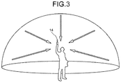
- FIG. 3 is a view illustrating an example of the usage of the imaging device 14 .
- the imaging device 14 is held in the hand of a user to image objects around the user.
- the imaging elements captures images conducted through the lens 20 A and the lens 20 B to image the objects around the user, so that two hemispherical images are obtained and an image in the solid angle of 4 ⁇ steradian is obtained.
- FIG. 4 ( FIG. 4A to FIG. 4C ) are views for explaining an image captured by the imaging device 14 .
- FIG. 4A illustrates a hemispherical image 42 A captured by the lens 20 A.
- FIG. 4B illustrates a hemispherical image 42 B captured by the lens 20 B.
- FIG. 4C illustrates a full-spherical panoramic image 42 represented by the Mercator projection.
- the lens 20 A is a fisheye lens that is one of wide angle lenses; therefore, an image obtained by the lens 20 A is the curved hemispherical image 42 A.
- the lens 20 B is a fisheye lens that is one of wide angle lenses; therefore, an image obtained by the lens 20 B is the curved hemispherical image 42 B.
- the hemispherical image 42 A and the hemispherical image 42 B are synthesized by the imaging device 14 , so that the full-spherical panoramic image 42 as illustrated in FIG. 4C is generated.
- the imaging device 14 when the imaging device 14 is connected to the information processing apparatus 12 , the full-spherical panoramic image 42 obtained by the imaging device 14 is transmitted from the imaging device 14 to the information processing apparatus 12 .
- the imaging device 14 transmits the full-spherical panoramic image 42 to the information processing apparatus 12 .
- the information processing apparatus 12 acquires the full-spherical panoramic image 42 from the imaging device 14 .
- the information processing apparatus 12 displays the acquired full-spherical panoramic image 42 on the display unit 16 , the UI unit 18 C, or the like using open graphic library (OpenGL).
- OpenGL open graphic library
- FIG. 5 is a diagram for explaining the hardware configuration of the information processing apparatus 12 .
- the information processing apparatus 12 includes a central processing unit (CPU) 30 that controls operations of the entire information processing apparatus 12 , a read only memory (ROM) 32 that stores therein a program, such as initial program loader (IPL), used to drive the CPU 30 , a random access memory (RAM) 34 used as a work area of the CPU 30 , a hard disk (HD) 38 that stores therein various kinds of data, such as a program used for the information processing apparatus 12 , and a hard disk drive (HDD) 36 that controls read and write of various kinds of data to and from the HD 38 under the control of the CPU 30 .
- CPU central processing unit
- ROM read only memory
- RAM random access memory
- HD hard disk
- HDD hard disk drive
- the information processing apparatus 12 includes a media drive 507 that controls read and write (storage) of data to and from a recording medium 506 , such as a flash memory, a display 508 that displays various images, an interface (I/F) 509 for communicating with the imaging device 14 and the operating unit 18 (the keyboard 18 A, the mouse 18 B, and the UI unit 18 C), a compact disc read only memory (CD-ROM) drive 514 that controls read and write of various kinds of data to and from a CD-ROM 513 that is one example of a removable recording medium, and a bus line 510 that electrically connects the above-described components.
- a media drive 507 controls read and write (storage) of data to and from a recording medium 506 , such as a flash memory
- a display 508 that displays various images
- an interface (I/F) 509 for communicating with the imaging device 14 and the operating unit 18 (the keyboard 18 A, the mouse 18 B, and the UI unit 18 C)
- CD-ROM compact disc read only memory
- An information processing program for executing information processing performed by the information processing apparatus 12 is incorporated in the ROM 32 or any other non-volatile storage medium in advance, to be provided. Furthermore, the information processing program executed by the information processing apparatus 12 may be recorded in a computer-readable recording medium (for example, the CD-ROM 513 ), such as a CD-ROM, a flexible disk (FD), a compact disc recordable (CD-R), or a digital versatile disk (DVD), in a computer-installable or computer-executable file format, to be provided.
- a computer-readable recording medium for example, the CD-ROM 513
- the CD-ROM 513 such as a CD-ROM, a flexible disk (FD), a compact disc recordable (CD-R), or a digital versatile disk (DVD)
- the information processing program executed by the information processing apparatus 12 may be stored in a computer connected to a network, such as the Internet, and may be downloaded via the network, to be provided or distributed.
- the information processing program executed by the information processing apparatus 12 may be incorporated in the ROM 32 or the like in advance, to be provided.
- FIG. 6 is a schematic diagram illustrating the functional configuration of the information processing apparatus 12 .
- the information processing apparatus 12 includes a control unit 52 , the operating unit 18 , such as the UI unit 18 C, and the HD 38 .
- the control unit 52 is electrically connected to the imaging device 14 , the display unit 16 , the operating unit 18 , such as the UI unit 18 C, and the HD 38 .
- the control unit 52 is a computer that controls the entire information processing apparatus 12 and includes the CPU 30 , the ROM 32 , the RAM 34 , or the like as described above.
- the control unit 52 may be constructed by a circuit or the like.
- the control unit 52 includes a connecting unit 54 , an importing unit 56 , a pasting unit 58 , an acquiring unit 60 , a generating unit 62 , a calculating unit 64 , and a display control unit 66 .
- a part or all of the connecting unit 54 , the importing unit 56 , the pasting unit 58 , the acquiring unit 60 , the generating unit 62 , the calculating unit 64 , and the display control unit 66 may be implemented by causing a processor, such as a CPU, to execute a program, that is, by software, for example.
- a part or all of the connecting unit 54 , the importing unit 56 , the pasting unit 58 , the acquiring unit 60 , the generating unit 62 , the calculating unit 64 , and the display control unit 66 may be implemented by hardware, such as an integrated circuit (IC), or by a combination of software and hardware.
- IC integrated circuit
- the information processing program executed by the information processing apparatus 12 has a module structure including the above-described units (the connecting unit 54 , the importing unit 56 , the pasting unit 58 , the acquiring unit 60 , the generating unit 62 , the calculating unit 64 , and the display control unit 66 ).
- the CPU 30 reads and executes the information processing program from a storage medium, so that the above-described units are loaded on a main storage device and generated on the main storage device.
- the connecting unit 54 establishes connection to the imaging device 14 .
- the connecting unit 54 performs communication control to establish a connection in accordance with a communication protocol that is defined in advance together with the imaging device 14 , when the imaging device 14 is connected to the information processing apparatus 12 in a wired or wireless manner. With this operation, the connecting unit 54 establishes connection to the imaging device 14 .
- the importing unit 56 imports the full-spherical panoramic image 42 from the imaging device 14 . It may be possible to store, in the HD 38 , the full-spherical panoramic image 42 imported from the imaging device 14 . In this case, the importing unit 56 may import the full-spherical panoramic image 42 from the HD 38 .
- the pasting unit 58 pastes the full-spherical panoramic image 42 obtained by imaging an omnidirectional range, along an inner wall of a virtual three-dimensional sphere arranged in a virtual three-dimensional space.
- FIG. 7 is a view for explaining pasting.
- the pasting unit 58 arranges a virtual three-dimensional sphere CS in a virtual three-dimensional space.
- the virtual three-dimensional sphere CS may be a sphere whose cross section is perfectly circular, or an ellipsoid whose cross section is elliptical.
- FIG. 7 as one example, the virtual three-dimensional sphere CS that is a sphere whose cross section is perfectly circular is illustrated.
- the pasting unit 58 pastes the full-spherical panoramic image 42 on an inner wall A of the virtual three-dimensional sphere CS.
- the pasted full-spherical panoramic image 42 is referred to as a full-spherical panoramic image 40 in the description below.
- the pasting unit 58 may paste the full-spherical panoramic image 42 on the virtual three-dimensional sphere CS using a three-dimensional (3D) graphic engine, such as OpenGL.
- 3D three-dimensional
- FIG. 8 is a view illustrating an example of the full-spherical panoramic image 40 .
- the full-spherical panoramic image 40 is obtained by pasting the full-spherical panoramic image 42 (see FIG. 4C ) on the inner wall A of the virtual three-dimensional sphere CS.
- FIG. 8 illustrates the full-spherical panoramic image 40 representing a state in which the inner wall A is observed in a certain line-of-sight direction from a center point P of the virtual three-dimensional sphere CS (see FIG. 7 ).
- the acquiring unit 60 acquires an embedding image to be embedded in the full-spherical panoramic image 42 .
- the embedding image may be any image to be embedded in the full-spherical panoramic image 42 , and specified by an operation instruction performed on the operating unit 18 by a user.
- the embedding image is, for example, a character image representing a character.
- the generating unit 62 generates a planar image in a form such that the embedding image is pasted on a two-dimensional plane. That is, the generating unit 62 arranges a two-dimensional plane (for example, a plate-like member) in the virtual three-dimensional space, and then pastes the embedding image on the two-dimensional plane, to generate the planar image.
- a two-dimensional plane for example, a plate-like member
- FIG. 9 is a schematic view illustrating an example of an embedding image 44 and a planar image 46 .
- the embedding image 44 is, for example, a character image, such as “ ⁇ building”.
- the generating unit 62 generates the planar image 46 obtained by pasting the embedding image 44 on a two-dimensional plane, for example.
- the acquiring unit 60 may further acquire shape information indicating a shape of the embedding image 44 .
- a user operates the UI unit 18 C to input an image to be embedded and shape information indicating the shape of the embedding image 44 .
- the acquiring unit 60 acquires the embedding image 44 that is a target image to be embedded, and the shape information from the UI unit 18 C.
- the acquiring unit 60 may further acquire size information indicating a size of the embedding image 44 .
- the size may be input appropriately by an operation instruction performed on the UI unit 18 C by the user.
- the size information is information indicating a display size of the embedding image 44 .
- the generating unit 62 may generate the planar image 46 obtained by pasting the embedding image 44 on a two-dimensional plane with a shape indicated by the shape information.
- the generating unit 62 generates the planar image 46 obtained by pasting the embedding image 44 on a quadrilateral two-dimensional plane.
- the generating unit 62 may generate the planar image 46 obtained by pasting the embedding image 44 is pasted on an elliptical two-dimensional plane.
- the generating unit 62 may generate the planar image 46 with a display size indicated by the size information.
- the calculating unit 64 calculates an arrangement position for arranging the planar image 46 closer to the center point P than the inner wall A of the virtual three-dimensional sphere CS.
- the calculating unit 64 calculates the arrangement position such that the planar image 46 is arranged closer to the center point P than the inner wall A of the virtual three-dimensional sphere CS (so as to be accommodated in the virtual three-dimensional sphere CS), in such an orientation that a line-of-sight direction from the center point P of the virtual three-dimensional sphere CS to the inner wall A and a perpendicular line of the planer image 46 are parallel to each other.
- FIG. 10 is a diagram for explaining a calculation of the arrangement position.
- the calculating unit 64 arranges the planar image 46 such that a line-of-sight direction L from the center point P to the inner wall A and a perpendicular line of the planer image 46 are parallel to each other.
- the calculating unit 64 calculates how much the planar image 46 should be moved from the inner wall A to the center point P along the line-of-sight direction L to arrange the entire planar image 46 such that the entire planar image 46 is accommodated in the virtual three-dimensional sphere CS while maintaining the above-described orientation.
- the calculating unit 64 acquires a size of the planar image 46 .
- the calculating unit 64 may acquire the size indicated by the size information acquired by the acquiring unit 60 , or may acquire the size from the planar image 46 generated by the generating unit 62 .
- the calculating unit 64 acquires a maximum length of the planar image 46 as a size d.
- the maximum length indicates a maximum length among sides and diagonal lines of the planar image 46 .
- the calculating unit 64 acquires a length of a diagonal line of the planar image 46 as the size d.
- the calculating unit 64 acquires a diameter of the planar image 46 as the size d.
- the calculating unit 64 calculates an angle ⁇ between two sides corresponding to the radius r around the center point P in a triangle formed by three sides including the two sides corresponding to the radius r and one side corresponding to the size d, in accordance with Expressions (1) and (2) below.
- the calculating unit 64 calculates a movement amount h by which the planar image 46 is to be moved from the inner wall A to the center point P along the line-of-sight direction L in accordance with Expression (3) below.
- h r ⁇ (1 ⁇ cos( ⁇ /2)) (3)
- the calculating unit 64 calculates, as the arrangement position of the planar image 46 , a position at which the planar image 46 is moved from the inner wall A toward the center point P by the movement amount h along the line-of-sight direction L (i.e., a position of (r-h) from the center point P) while maintaining the orientation in which the perpendicular line of the planer image 46 is parallel to the line-of-sight direction L.
- the planar image 46 arranged at the calculated arrangement position (the position separated from the inner wall A by the movement amount h) is brought into a state in which the planar image 46 is accommodated in the virtual three-dimensional sphere CS, and the perpendicular line is parallel to the line-of-sight direction L. Furthermore, the planar image 46 is arranged at a position closer to the center point P than the inner wall A of the virtual three-dimensional sphere CS.
- the display control unit 66 generates a display image obtained by converting a state in which the full-spherical panoramic image 40 is pasted on the inner wall A of the virtual three-dimensional sphere CS and the planar image 46 is arranged at the arrangement position calculated by the calculating unit 64 , to a two-dimensional image viewed from the center point P in the line-of-sight direction L.
- the conversion from the above-described state to the two-dimensional image may be performed using 3D graphic engine (OpenGL or the like).
- the display control unit 66 displays the generated display image on the display unit 16 or the UI unit 18 C.
- FIG. 11 is a view illustrating an example of a display image 48 .
- the display control unit 66 displays the display image 48 on the display unit 16 or the UI unit 18 C.
- the display image 48 is an image in which the planar image 46 obtained by pasting the embedding image 44 on a two-dimensional plane is synthesized on the full-spherical panoramic image 40 .
- the full-spherical panoramic image 40 is an image obtained by pasting the full-spherical panoramic image 42 on the inner wall A of the virtual three-dimensional sphere CS. Therefore, the image is distorted as compared to an actual landscape (see FIG. 11 ).
- the display image 48 is an image representing a state in which the planar image 46 obtained by pasting the embedding image 44 on a two-dimensional plane is arranged at the calculated arrangement position in the virtual three-dimensional sphere CS, in such an orientation that the line-of-sight direction L from the center point P to the inner wall A and the perpendicular line of the planer image 46 are parallel to each other, and is viewed from the center point P in the line-of-sight direction L. That is, the embedding image 44 is arranged in front of (closer to the center point P than) a three-dimensional model formed by the full-spherical panoramic image 40 .
- the planar image 46 included in the display image 48 represents a state in which the planar image 46 is viewed in a perpendicular direction with respect to the line-of-sight direction L. That is, the planar image 46 is displayed without distortion.
- FIG. 12 is a flowchart illustrating the flow of information processing performed by the control unit 52 of the information processing apparatus 12 .
- the importing unit 56 acquires the full-spherical panoramic image 42 to be displayed on the display unit 16 (Step S 100 ). For example, a user operates the UI unit 18 C to specify the full-spherical panoramic image 42 as a display target.
- the importing unit 56 acquires, from the HD 38 , the full-spherical panoramic image 42 that is a display target received from the UI unit 18 C.
- the importing unit 56 may acquire the full-spherical panoramic image 42 from the imaging device 14 .
- the pasting unit 58 pastes the full-spherical panoramic image 42 acquired at Step S 100 on the inner wall A of the virtual three-dimensional sphere CS arranged in the virtual three-dimensional space (Step S 102 ) (see FIG. 7 and FIG. 8 ).
- the acquiring unit 60 acquires the embedding image 44 to be embedded in the full-spherical panoramic image 42 (Step S 104 ).
- the generating unit 62 generates the planar image 46 obtained by pasting the embedding image 44 on a two-dimensional plane (Step S 106 ).
- the calculating unit 64 calculates an arrangement position for arranging the planar image 46 closed to the center point P than the inner wall A of the virtual three-dimensional sphere CS (Step S 108 ) (details will be described later).
- the display control unit 66 pastes the full-spherical panoramic image 40 on the inner wall A of the virtual three-dimensional sphere CS and arranges the planar image 46 at the arrangement position calculated at Step S 108 (Step S 110 ). Then, the display control unit 66 generates the display image 48 obtained by converting the above-described state to a two-dimensional image viewed from the center point P in the line-of-sight direction L.
- the display control unit 66 displays the generated display image on the display unit 16 or the UI unit 18 C (Step S 112 ). Then, the routine is finished.
- FIG. 13 is a flowchart illustrating the flow of the arrangement position calculation process.
- the calculating unit 64 arranges the planar image 46 such that the line-of-sight direction L from the center point P toward the inner wall A and the perpendicular line of the planer image 46 are parallel to each other. Then, the calculating unit 64 acquires a size of the planar image 46 (Step S 200 ). For example, the calculating unit 64 acquires the maximum length of the planar image 46 as the size d.
- the calculating unit 64 calculates the angle ⁇ between the two sides corresponding to the radius r around the center point P in the triangle formed by three sides including the two sides corresponding to the radius r and one side corresponding to the size d, based on the radius r of the virtual three-dimensional sphere CS and the acquired size d in accordance with Expression (1) and (2) as described above (Step S 202 ).
- the calculating unit 64 calculates, as the arrangement position of the planar image 46 , a position at which the planar image 46 is moved from the inner wall A toward the center point P by the movement amount h along the line-of-sight direction L (i.e., the position of (r-h) from the center point P) (Step S 204 ). Then, the routine is finished.
- the information processing apparatus 12 includes the pasting unit 58 , the acquiring unit 60 , the generating unit 62 , the calculating unit 64 , and the display control unit 66 .
- the pasting unit 58 pastes the full-spherical panoramic image 42 obtained by imaging an omnidirectional range, along the inner wall A of the virtual three-dimensional sphere CS arranged in the virtual three-dimensional space.
- the acquiring unit 60 acquires the embedding image 44 to be embedded in the full-spherical panoramic image 42 .
- the generating unit 62 generates the planar image 46 obtained by pasting the embedding image 44 on the two-dimensional plane.
- the calculating unit 64 calculates an arrangement position for arranging the planar image 46 closer to the center point P than the inner wall A of the virtual three-dimensional sphere CS, in such an orientation that the line-of-sight direction L from the center point P to the inner wall A of the virtual three-dimensional sphere CS and the perpendicular line of the planer image 46 are parallel to each other.
- the display control unit 66 displays, on the display unit 16 , the display image 48 obtained by converting a state in which the full-spherical panoramic image 40 is obtained by pasting the full-spherical panoramic image 42 along the inner wall A of the virtual three-dimensional sphere CS and the planar image 46 is arranged at the arrangement position, to a two-dimensional image viewed from the center point P in the line-of-sight direction L.
- the planar image 46 included in the display image 48 represents a state in which the planar image 46 is viewed in a perpendicular direction with respect to the line-of-sight direction L. That is, the planar image 46 embedded in the full-spherical panoramic image 40 is displayed without distortion.
- the embedding image 44 embedded in the full-spherical panoramic image 42 can be displayed without distortion.
- the embedding image 44 is embedded along the inner wall A on the full-spherical panoramic image 40 that is obtained by arranging the full-spherical panoramic image 42 along the inner wall A of the virtual three-dimensional sphere CS. Therefore, conventionally, the embedding image 44 is displayed in a distorted manner along the inner wall A of the virtual three-dimensional sphere CS.
- the information processing apparatus 12 generates the planar image 46 obtained by pasting the embedding image 44 to be embedded in the full-spherical panoramic image 42 , on a two-dimensional plane, and arranges the planar image 46 closer to the center point P than the inner wall A of the virtual three-dimensional sphere CS. Therefore, the planar image 46 embedded in the full-spherical panoramic image 40 is displayed without distortion.
- the virtual three-dimensional sphere CS is a sphere whose cross section is perfectly circular or an ellipsoid whose cross section is elliptical.
- the embedding image 44 includes a character image.
- the acquiring unit 60 may acquire shape information indicating a shape of the embedding image 44
- the generating unit 62 may generate the planar image 46 obtained by pasting the embedding image 44 on a two-dimensional plane with a shape indicated by the shape information.
- an effect of enabling the detection error of the interval between the patch images on the secondary transfer belt to be reduced and of enabling an excellent color image having a small color shift or a small color matching variation to be obtained, is achieved.
- any of the above-described apparatus, devices or units can be implemented as a hardware apparatus, such as a special-purpose circuit or device, or as a hardware/software combination, such as a processor executing a software program.
- any one of the above-described and other methods of the present invention may be embodied in the form of a computer program stored in any kind of storage medium.
- storage mediums include, but are not limited to, flexible disk, hard disk, optical discs, magneto-optical discs, magnetic tapes, nonvolatile memory, semiconductor memory, read-only-memory (ROM), etc.
- any one of the above-described and other methods of the present invention may be implemented by an application specific integrated circuit (ASIC), a digital signal processor (DSP) or a field programmable gate array (FPGA), prepared by interconnecting an appropriate network of conventional component circuits or by a combination thereof with one or more conventional general purpose microprocessors or signal processors programmed accordingly.
- ASIC application specific integrated circuit
- DSP digital signal processor
- FPGA field programmable gate array
- Processing circuitry includes a programmed processor, as a processor includes circuitry.
- a processing circuit also includes devices such as an application specific integrated circuit (ASIC), digital signal processor (DSP), field programmable gate array (FPGA) and conventional circuit components arranged to perform the recited functions.
- ASIC application specific integrated circuit
- DSP digital signal processor
- FPGA field programmable gate array
Priority Applications (1)
| Application Number | Priority Date | Filing Date | Title |
|---|---|---|---|
| US16/875,230 US10923004B2 (en) | 2015-04-06 | 2020-05-15 | Information processing apparatus, information processing method, and computer program product for arranging a planar image within a panoramic image |
Applications Claiming Priority (3)
| Application Number | Priority Date | Filing Date | Title |
|---|---|---|---|
| JP2015077766 | 2015-04-06 | ||
| JP2015-077766 | 2015-04-06 | ||
| PCT/JP2016/061059 WO2016163342A1 (ja) | 2015-04-06 | 2016-04-05 | 情報処理装置、情報処理方法、および情報処理プログラム |
Related Parent Applications (1)
| Application Number | Title | Priority Date | Filing Date |
|---|---|---|---|
| PCT/JP2016/061059 Continuation WO2016163342A1 (ja) | 2015-04-06 | 2016-04-05 | 情報処理装置、情報処理方法、および情報処理プログラム |
Related Child Applications (1)
| Application Number | Title | Priority Date | Filing Date |
|---|---|---|---|
| US16/875,230 Continuation US10923004B2 (en) | 2015-04-06 | 2020-05-15 | Information processing apparatus, information processing method, and computer program product for arranging a planar image within a panoramic image |
Publications (2)
| Publication Number | Publication Date |
|---|---|
| US20180012529A1 US20180012529A1 (en) | 2018-01-11 |
| US10692409B2 true US10692409B2 (en) | 2020-06-23 |
Family
ID=57072602
Family Applications (2)
| Application Number | Title | Priority Date | Filing Date |
|---|---|---|---|
| US15/712,285 Active 2036-04-17 US10692409B2 (en) | 2015-04-06 | 2017-09-22 | Information processing apparatus, information processing method, and computer program product for arranging a planar image in a full-spherical panoramic image obtained by imaging an omnidirectional range |
| US16/875,230 Active US10923004B2 (en) | 2015-04-06 | 2020-05-15 | Information processing apparatus, information processing method, and computer program product for arranging a planar image within a panoramic image |
Family Applications After (1)
| Application Number | Title | Priority Date | Filing Date |
|---|---|---|---|
| US16/875,230 Active US10923004B2 (en) | 2015-04-06 | 2020-05-15 | Information processing apparatus, information processing method, and computer program product for arranging a planar image within a panoramic image |
Country Status (6)
| Country | Link |
|---|---|
| US (2) | US10692409B2 (de) |
| EP (1) | EP3282687B1 (de) |
| JP (3) | JP6394794B2 (de) |
| CN (1) | CN107431765B (de) |
| CA (1) | CA2981134A1 (de) |
| WO (1) | WO2016163342A1 (de) |
Families Citing this family (14)
| Publication number | Priority date | Publication date | Assignee | Title |
|---|---|---|---|---|
| US10222932B2 (en) | 2015-07-15 | 2019-03-05 | Fyusion, Inc. | Virtual reality environment based manipulation of multilayered multi-view interactive digital media representations |
| US11006095B2 (en) | 2015-07-15 | 2021-05-11 | Fyusion, Inc. | Drone based capture of a multi-view interactive digital media |
| US11095869B2 (en) * | 2015-09-22 | 2021-08-17 | Fyusion, Inc. | System and method for generating combined embedded multi-view interactive digital media representations |
| US10242474B2 (en) | 2015-07-15 | 2019-03-26 | Fyusion, Inc. | Artificially rendering images using viewpoint interpolation and extrapolation |
| US10147211B2 (en) | 2015-07-15 | 2018-12-04 | Fyusion, Inc. | Artificially rendering images using viewpoint interpolation and extrapolation |
| US11783864B2 (en) | 2015-09-22 | 2023-10-10 | Fyusion, Inc. | Integration of audio into a multi-view interactive digital media representation |
| US11202017B2 (en) | 2016-10-06 | 2021-12-14 | Fyusion, Inc. | Live style transfer on a mobile device |
| US10339627B2 (en) * | 2016-10-10 | 2019-07-02 | Gopro, Inc. | Apparatus and methods for the optimal stitch zone calculation of a generated projection of a spherical image |
| US10437879B2 (en) | 2017-01-18 | 2019-10-08 | Fyusion, Inc. | Visual search using multi-view interactive digital media representations |
| US10313651B2 (en) | 2017-05-22 | 2019-06-04 | Fyusion, Inc. | Snapshots at predefined intervals or angles |
| CN107169924B (zh) * | 2017-06-14 | 2020-10-09 | 歌尔科技有限公司 | 三维全景图像的建立方法和系统 |
| US11069147B2 (en) | 2017-06-26 | 2021-07-20 | Fyusion, Inc. | Modification of multi-view interactive digital media representation |
| US10592747B2 (en) | 2018-04-26 | 2020-03-17 | Fyusion, Inc. | Method and apparatus for 3-D auto tagging |
| CN111954054B (zh) * | 2020-06-05 | 2022-03-04 | 筑觉绘(上海)科技有限公司 | 图像处理方法、系统、存储介质及计算机设备 |
Citations (9)
| Publication number | Priority date | Publication date | Assignee | Title |
|---|---|---|---|---|
| EP0838787A2 (de) | 1996-10-16 | 1998-04-29 | HE HOLDINGS, INC. dba HUGHES ELECTRONICS | Verfahren und System für virtuelle Realität in Echtzeit mit mehreren Benutzern |
| JPH10334272A (ja) | 1997-05-27 | 1998-12-18 | Ibm Japan Ltd | 3次元形状モデルへの情報の埋め込み方法及びシステム |
| JP2004214830A (ja) | 2002-12-27 | 2004-07-29 | Iwane Kenkyusho:Kk | 一部リアルタイム画像表示装置 |
| JP2007089111A (ja) | 2005-08-26 | 2007-04-05 | Kazuo Iwane | 二次元図面と映像の合成表示装置 |
| CN102129717A (zh) | 2011-03-09 | 2011-07-20 | 上海诚明融鑫科技有限公司 | 一种实现三维全景空间中通过热点浏览全景的方法和系统 |
| JP2013198062A (ja) | 2012-03-22 | 2013-09-30 | Ricoh Co Ltd | 画像処理装置、画像処理方法及び撮像装置 |
| US20140210940A1 (en) * | 2013-01-31 | 2014-07-31 | Navteq B.V. | Stereo panoramic images |
| JP2014165764A (ja) | 2013-02-26 | 2014-09-08 | Ricoh Co Ltd | 編集装置、編集方法、及び編集プログラム |
| US20150077416A1 (en) * | 2013-03-13 | 2015-03-19 | Jason Villmer | Head mounted display for viewing and creating a media file including omnidirectional image data and corresponding audio data |
Family Cites Families (1)
| Publication number | Priority date | Publication date | Assignee | Title |
|---|---|---|---|---|
| JP2009187306A (ja) * | 2008-02-06 | 2009-08-20 | G1 Systems Inc | 映像閲覧システム |
-
2016
- 2016-04-05 CA CA2981134A patent/CA2981134A1/en not_active Abandoned
- 2016-04-05 CN CN201680019781.6A patent/CN107431765B/zh active Active
- 2016-04-05 WO PCT/JP2016/061059 patent/WO2016163342A1/ja active Application Filing
- 2016-04-05 EP EP16776508.0A patent/EP3282687B1/de active Active
- 2016-04-05 JP JP2017510980A patent/JP6394794B2/ja not_active Expired - Fee Related
-
2017
- 2017-09-22 US US15/712,285 patent/US10692409B2/en active Active
-
2018
- 2018-08-29 JP JP2018160378A patent/JP6627935B2/ja active Active
-
2019
- 2019-12-02 JP JP2019218331A patent/JP6816812B2/ja active Active
-
2020
- 2020-05-15 US US16/875,230 patent/US10923004B2/en active Active
Patent Citations (11)
| Publication number | Priority date | Publication date | Assignee | Title |
|---|---|---|---|---|
| EP0838787A2 (de) | 1996-10-16 | 1998-04-29 | HE HOLDINGS, INC. dba HUGHES ELECTRONICS | Verfahren und System für virtuelle Realität in Echtzeit mit mehreren Benutzern |
| US6317127B1 (en) | 1996-10-16 | 2001-11-13 | Hughes Electronics Corporation | Multi-user real-time augmented reality system and method |
| JPH10334272A (ja) | 1997-05-27 | 1998-12-18 | Ibm Japan Ltd | 3次元形状モデルへの情報の埋め込み方法及びシステム |
| US6201881B1 (en) | 1997-05-27 | 2001-03-13 | International Business Machines Corporation | Embedding information in three-dimensional geometric model |
| JP2004214830A (ja) | 2002-12-27 | 2004-07-29 | Iwane Kenkyusho:Kk | 一部リアルタイム画像表示装置 |
| JP2007089111A (ja) | 2005-08-26 | 2007-04-05 | Kazuo Iwane | 二次元図面と映像の合成表示装置 |
| CN102129717A (zh) | 2011-03-09 | 2011-07-20 | 上海诚明融鑫科技有限公司 | 一种实现三维全景空间中通过热点浏览全景的方法和系统 |
| JP2013198062A (ja) | 2012-03-22 | 2013-09-30 | Ricoh Co Ltd | 画像処理装置、画像処理方法及び撮像装置 |
| US20140210940A1 (en) * | 2013-01-31 | 2014-07-31 | Navteq B.V. | Stereo panoramic images |
| JP2014165764A (ja) | 2013-02-26 | 2014-09-08 | Ricoh Co Ltd | 編集装置、編集方法、及び編集プログラム |
| US20150077416A1 (en) * | 2013-03-13 | 2015-03-19 | Jason Villmer | Head mounted display for viewing and creating a media file including omnidirectional image data and corresponding audio data |
Non-Patent Citations (4)
| Title |
|---|
| Chinese Office Action dated Jul. 3, 2019. |
| Extended European Search Report dated Feb. 20, 2018. |
| International Search Report dated Jun. 28, 2016 in PCT/JP2016/061059 filed Apr. 5, 2016. |
| Written Opinion of the International Searching Authority PCT/ISA/237 for International Application No. PCT/JP2016/061059 dated Jun. 28, 2016. |
Also Published As
| Publication number | Publication date |
|---|---|
| JP6816812B2 (ja) | 2021-01-20 |
| EP3282687B1 (de) | 2020-11-11 |
| EP3282687A1 (de) | 2018-02-14 |
| JP2019024203A (ja) | 2019-02-14 |
| JP2020053080A (ja) | 2020-04-02 |
| EP3282687A4 (de) | 2018-03-21 |
| JPWO2016163342A1 (ja) | 2017-11-16 |
| CN107431765A (zh) | 2017-12-01 |
| CA2981134A1 (en) | 2016-10-13 |
| US20180012529A1 (en) | 2018-01-11 |
| JP6394794B2 (ja) | 2018-09-26 |
| US10923004B2 (en) | 2021-02-16 |
| US20200279515A1 (en) | 2020-09-03 |
| JP6627935B2 (ja) | 2020-01-08 |
| WO2016163342A1 (ja) | 2016-10-13 |
| CN107431765B (zh) | 2020-11-27 |
Similar Documents
| Publication | Publication Date | Title |
|---|---|---|
| US10923004B2 (en) | Information processing apparatus, information processing method, and computer program product for arranging a planar image within a panoramic image | |
| KR102183050B1 (ko) | 구면 파노라마 영상에 매핑을 수행하는 방법 및 장치 | |
| JP5847924B2 (ja) | 拡張現実表現のための二次元画像取込み | |
| CN107833219B (zh) | 图像识别方法及装置 | |
| US9852336B2 (en) | Relative positioning of a mobile computing device in a network | |
| US9135678B2 (en) | Methods and apparatus for interfacing panoramic image stitching with post-processors | |
| CN104145474A (zh) | 引导式图像拍摄 | |
| JP2014112302A (ja) | 所定領域管理システム、通信方法、及びプログラム | |
| CN111932664A (zh) | 图像渲染方法、装置、电子设备及存储介质 | |
| US20140354784A1 (en) | Shooting method for three dimensional modeling and electronic device supporting the same | |
| TW202121343A (zh) | 圖像處理方法及裝置、電子設備和電腦可讀儲存媒體 | |
| US20160163057A1 (en) | Three-Dimensional Shape Capture Using Non-Collinear Display Illumination | |
| CN114529606A (zh) | 位姿检测方法及装置、电子设备和存储介质 | |
| TW201913575A (zh) | 三維影像重建方法、裝置及其非暫態電腦可讀取儲存媒體 | |
| EP4268200A1 (de) | Bilddatenanmerkungssystem | |
| JP2017515345A (ja) | 一連の画像からベース画像と再配置されるオブジェクトとを合成する画像生成 | |
| US10748333B2 (en) | Finite aperture omni-directional stereo light transport | |
| JP2017182681A (ja) | 画像処理システム、情報処理装置、プログラム | |
| US20210303824A1 (en) | Face detection in spherical images using overcapture | |
| KR20110074442A (ko) | 화상 처리 장치, 화상 처리 방법 및 기록매체 | |
| JP2017184025A (ja) | 通信端末、画像通信システム、画像送信方法、画像表示方法、及びプログラム | |
| EP2590398A2 (de) | Anzeige von Bildern mit Beleuchtung auf der Basis erfasster zusätzlicher Bilder | |
| JP2020088571A (ja) | 管理システム、情報処理システム、情報処理方法およびプログラム | |
| US20110157314A1 (en) | Image Processing Apparatus, Image Processing Method and Recording Medium | |
| KR20200019361A (ko) | 3차원 얼굴 인식을 위한 장치 및 방법 |
Legal Events
| Date | Code | Title | Description |
|---|---|---|---|
| AS | Assignment |
Owner name: RICOH COMPANY, LTD., JAPAN Free format text: ASSIGNMENT OF ASSIGNORS INTEREST;ASSIGNOR:CHIBA, TAKETO;REEL/FRAME:043664/0054 Effective date: 20170914 |
|
| FEPP | Fee payment procedure |
Free format text: ENTITY STATUS SET TO UNDISCOUNTED (ORIGINAL EVENT CODE: BIG.); ENTITY STATUS OF PATENT OWNER: LARGE ENTITY |
|
| STPP | Information on status: patent application and granting procedure in general |
Free format text: NON FINAL ACTION MAILED |
|
| STPP | Information on status: patent application and granting procedure in general |
Free format text: RESPONSE TO NON-FINAL OFFICE ACTION ENTERED AND FORWARDED TO EXAMINER |
|
| STPP | Information on status: patent application and granting procedure in general |
Free format text: FINAL REJECTION MAILED |
|
| STPP | Information on status: patent application and granting procedure in general |
Free format text: DOCKETED NEW CASE - READY FOR EXAMINATION |
|
| STPP | Information on status: patent application and granting procedure in general |
Free format text: NOTICE OF ALLOWANCE MAILED -- APPLICATION RECEIVED IN OFFICE OF PUBLICATIONS |
|
| STPP | Information on status: patent application and granting procedure in general |
Free format text: PUBLICATIONS -- ISSUE FEE PAYMENT RECEIVED |
|
| STCF | Information on status: patent grant |
Free format text: PATENTED CASE |
|
| MAFP | Maintenance fee payment |
Free format text: PAYMENT OF MAINTENANCE FEE, 4TH YEAR, LARGE ENTITY (ORIGINAL EVENT CODE: M1551); ENTITY STATUS OF PATENT OWNER: LARGE ENTITY Year of fee payment: 4 |